Thank you for choosing EnviroVent
|
|
|
- Joseph Griffin
- 6 years ago
- Views:
Transcription
1
2

3 01 Introduction Thank you for choosing EnviroVent The fastest growing ventilation company in the UK You are about to install a product that is designed to outlast the life-cycle of the building. Once installed the unit will operate continuously for 5 years and beyond without a major service. Please therefore ensure that this product is treated with care and installed properly i.e. for the life of the building. If the unit is mishandled you might break it! This invalidates the warranty. And remember, if you have any problems please call our dedicated Technical Team. We are always pleased to help and in an emergency will come out to site quickly, completely free of charge. Scan the QR code to watch the step by step installation video. HOTLINE: Due to our policy of continuous innovation and improvement EnviroVent reserves the right to alter products specification and appearance without notice. AFTER INSTALLING THIS UNIT PLEASE PASS ONTO END USER DO NOT THROW AWAY 02
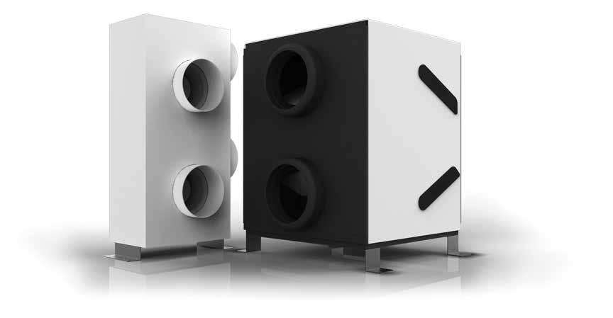
4 02 About The Unit The energisava 380 is a modular whole house heat recovery unit which works by continuously extracting stale, moisture-laden air from the Wet Rooms of the apartment or a house - the kitchen, bathroom and en-suite rooms - and ducts this to a central unit. This extracted air passes through a high efficiency counter-flow heat exchanger before being ducted to the outside. Fresh air is drawn into the unit from outside, which is warmed by the heat exchange cell and delivered into the living, dining and bedroom areas. The unit can be installed in a loft space or utility area. Humidity sensing- This unit is fitted with humidity tracking as standard to maintain the required ventilation rates in the wet rooms of the accommodation. Frost protection - when the cell temperature falls below 5 C the unit automatically warms the cell with extracted air to prevent the formation of frost. For unit controls see page 18. EXPLODED VIEW (fan module) Fan module Fan assembly Access panel energisava 380 (LH Mount) Fan bracket RH mount 03 SHOULD YOU ENCOUNTER ANY PROBLEMS INSTALLING THIS UNIT CALL
5 03 Wiring Diagram Left Hand Mounting Right Hand Mounting Switch live Boost 230V 3 core power cable. 230V Wire to 3A fuse spur For summer bypass connect to SBP Switch live Boost 230V 3 core power cable. 230V Wire to 3A fuse spur For summer bypass connect to SBP Emergency shutdown details - Unit to be isolated from the mains by turning it off at the isolating switch, this should be located within 1m of the unit. After Sales Service - We recommend you do not dismantle or remove any other parts than those mentioned, as any tampering would automatically cancel the guarantee. If you detect any fault please contact EnviroVent. AFTER INSTALLING THIS UNIT PLEASE PASS ONTO END USER DO NOT THROW AWAY 04
6 04 Technical Specifications Supply Voltage Dimensions (w x h x d) mm Ventilation Capacity 230v / 50Hz / 168W MAX / 1.4A MAX FAN UNIT x 686 x 237 (including mounting brackets) HEAT CELL x 643 x 566 Supply Airflow Extract Airflow pa, Max 125 l/s pa, Max 125 l/s Approvals LH RH EMC testing (Electromagnetic Compatibility) Emissions EN A1: 2009 EN : A1: 2009 EN : 2008 Immunity EN : A1: A2: 2008 LVD testing (Low Voltage Directive) EN : A2: EN : A15: 2011 This product shall be installed according to EnviroVent instructions and other relevant industry standards and regulations. 05 SHOULD YOU ENCOUNTER ANY PROBLEMS INSTALLING THIS UNIT CALL
7 04 Technical Specifications Product Dimensions (mm) Fan Module LH Mount Fan Module RH Mount LH & RH Mount Heat Exchange Block The energisava 380 unit should be situated so that access for maintenance is possible. *Fixing centres. AFTER INSTALLING THIS UNIT PLEASE PASS ONTO END USER DO NOT THROW AWAY 06
8 04 Technical Specifications Control Panel 2 Supply Fan 3 Extract Fan 4 Steel mount - Fan Tower 5 Extraction connection between Heat Exchanger and Fan Tower 6 Steel mount - Heat Recovery Cell 7 Drain fitting 8 Heat Recovery Cell 9 Filter - Supply 10 Ø150mm inside diameter spigot; from atmosphere to deliver fresh air into property 11 Ø150mm inside diameter spigot; from dwelling 12 Filter - Extract 13 Supply connection between Heat Exchanger and Fan Tower 07 SHOULD YOU ENCOUNTER ANY PROBLEMS INSTALLING THIS UNIT CALL
9 05 Installation Instructions IMPORTANT Be sure to have read and understood these instructions before beginning the installation process. PRE-INSTALLATION CHECK LIST Make sure that the unit can physically fit in to the desired location. The unit requires a standard 720 x 560mm loft opening. The energisava 380 unit should be situated so that access for maintenance or replacement of parts is possible. Use maximum diameter ductwork ensuring that runs are as short as possible. Having the most direct route and using as few bends as possible will reduce air resistance and improve the efficiency of the unit. SAFETY AND RECOMMENDATIONS All wiring must comply with Building Regulations and the current I.E.E. Wiring Regulations (BS7671) or the equivalent standards for your country. The final installation should be examined and tested by a qualified electrician. The means of disconnection from the mains supply must be incorporated in the fixed wiring in accordance with the wiring rules. If the supply cord is damaged it must be replaced by the manufacturer, its service agent or similarly qualified persons in order to avoid a hazard. Precautions must be taken to avoid the back-flow of gases into the dwelling from the open flue of gas or other fuel-burning appliances. Make sure that the external supply and extract grilles are at least 1m away from any gas flue outlet (increase to 3m if mounted directly above a flue). Ensure that the MVHR s external supply and extract grilles are 2m apart. Make sure the mains supply complies with the rating label for voltage, frequency and phase. This appliance can be used by children aged from 8 years and above and persons with reduced physical, sensory or mental capabilities or lack of experience and knowledge if they have been given supervision or instruction concerning use of the appliance in a safe way and understand the hazards involved. Children shall not play with the appliance. Cleaning and user maintenance shall not be made by children without supervision. AFTER INSTALLING THIS UNIT PLEASE PASS ONTO END USER DO NOT THROW AWAY 08
10 05 Installation Instructions Control Options Frost Protection When the cell temperature in the unit falls below 3ºC the unit automatically warms the cell with extracted air to prevent the formation of frost. Boost - Switch Live The energisava 380 comes with Switch Live as standard. It is an automatic function, sending the unit to boost when the bathroom or kitchen light is on. Summer Bypass Summer bypass is fitted as standard and helps reduce the air temperature coming into the dwelling during the summer months. It is an automatic function and operates when the supply air temperature to the property is above 25ºC. Control Options Frost Protection Boost Switch Live Summer Bypass Humidity Tracking Boost - Remote Control Humidity Tracking When the energisava 380 unit senses a rise in humidity, caused by increased moisture generation such as through cooking or showering, the extract and supply airflows will slowly begin to increase in direct proportion to the increase in humidity. It will then automatically track back down again when humidity falls. This controls condensation quietly and efficiently. Boost - Remote Control The energisava 380 unit also comes with a remote control switch which can be used at any time to send the unit to boost for 20 mins (see pg 18). 09 SHOULD YOU ENCOUNTER ANY PROBLEMS INSTALLING THIS UNIT CALL

11 05 Installation Instructions What s in the box Description Quantity Item Heat Exchange Block (Cell Housing Unit) 1x Box 1 Mounting Bracket 30mm Screw 2x 6x Fan Module 1x Box 2 LH Mount Bracket RH Mount Bracket M5 x 16mm Screw Spare Strain Relief Block 1x 2x 4x 1x Boost Switch 1x Fixing Kit Sealing Strip Foam Pad Penny Washer 50mm Screw 4x 16x 8x 8x AFTER INSTALLING THIS UNIT PLEASE PASS ONTO END USER DO NOT THROW AWAY 10
12 05 Installation Instructions Ducts from dwelling (Ø150mm); insulated within loft space 2 Ducts to dwelling (Ø150mm); insulated within loft space, with 1.5-2m of acoustic ducting attached to unit 3 Extract duct to atmosphere (Ø150mm); insulated flexible ducting recommended 4 Recommended location ventilation air output 5 Position the unit on wooden battens (not supplied) laid across the joists 6 Supply duct from atmosphere to draw fresh air to dwelling (Ø150mm) 7 Recommended fresh air inlet 11 SHOULD YOU ENCOUNTER ANY PROBLEMS INSTALLING THIS UNIT CALL
13 05 Installation Instructions Installation Example UTILITY WC KITCHEN/ DINING BATHROOM BEDROOM 2 OFFICE BEDROOM 1 BEDROOM 3 LOUNGE GROUND FLOOR FIRST FLOOR SUPPLY EXTRACT EXHAUST ATMOSPHERE FIRST FIX 1. Duct within house - use Ø150mm or 204 x 54mm where necessary (also see points 3 & 4 second fix). 2. Power to the unit - locate a 3 amp fused spur within 1m of the unit. SECOND FIX - 1. Setup the fan unit and decide the mounting orientation. a) LEFT HAND MOUNT (LH) (Standard mounting orientation) Fix the mounting bracket to the underside of the unit with 4 x M5 x 16mm screws as shown. Apply self adhesive rubber mounts to the underside of the brackets, over the four mounting holes. AFTER INSTALLING THIS UNIT PLEASE PASS ONTO END USER DO NOT THROW AWAY 12

14 05 Installation Instructions SECOND FIX CONT b) RIGHT HAND MOUNT (RH) Fix the mounting strips to the underside of the unit with 4 x M5 x 16mm screws as shown. Apply self adhesive rubber mounts to the underside of the brackets, over the four mounting holes. On RH mount units only, the fan signal connectors should be swapped over on the PCB control board to ensure proper function of the unit. Units are configured for LH mounting as standard. The PCB control board is found behind the electronics cover on the reverse of the fan unit. For RH mount, reverse fan signal connections. The extract fan is always located at the bottom of the fan tower. The bottom fan must always be positioned on fan connector 2 indicated as FAN 2 on the PCB. 13 SHOULD YOU ENCOUNTER ANY PROBLEMS INSTALLING THIS UNIT CALL
15 05 Installation Instructions SECOND FIX CONT. 2. Setup the heat cell a) Brackets- Fix brackets x 2 onto the base of the heat cell unit using 6 x 30mm screws as shown. Ensure that the card sleeve is in place to protect the white cover. Apply self adhesive rubber mounts to the underside of the bracket, over the four mounting holes. 3. Mounting a) Position the energisava 380 fan unit and heat cell on a plywood sheet or battens. Joists Plywood sheet Wooden battens b) The unit must be mounted so that the feet are facing down and the units are level. c) Push the two sections together so that the Ø150 spigots on the fan unit are fully located inside the heat cell spigot. b) Condense pipe - Fix the required length of condense pipe into the drain with solvent. d) Unit connection must be fully sealed. e) Sealing strips provided may be used to help seal units. AFTER INSTALLING THIS UNIT PLEASE PASS ONTO END USER DO NOT THROW AWAY 14

 Humidity Black b) Frost sensor Blue c) Internal temperature sensor Red b) Connect to the volt free boost if required (non-remote control versions only).")
16 05 Installation Instructions SECOND FIX CONT. 3. Mounting f) If you are fitting an option summer bypass ensure 350mm clearance between the units. Make sure that any ducting fitted between the two units is insulated and slopes slightly towards the heat cell. g) Lightly secure the units with 8 x 50mm screws and the additional rubber mount and large washers. Do not over tighten the screws. a) Humidity Black b) Frost sensor Blue c) Internal temperature sensor Red b) Connect to the volt free boost if required (non-remote control versions only). The connection is located behind the rear panel on the fan unit. (See fig.2). Orientation not important. Closed to boost. h) Make sure that the connection between the fan unit and heat cell are airtight. 4. Connecting to the unit a) Connect the three sensor cables so that the colours match. The sensors are located behind the rear panel on the fan unit and tapped to the spigot on the heat cell. c) On summer bypass specified units, connect the bypass to the connector on the control PCB located behind the electronics cover. Switched live boost input 230V Fig.1 Summer bypass 15 SHOULD YOU ENCOUNTER ANY PROBLEMS INSTALLING THIS UNIT CALL
17 05 Installation Instructions SECOND FIX CONT. 4. Connecting to the unit d) Where switch live boost is required, fix the live from the lighting circuit to one of the four switch live connection points. Use spare strain relief block on live wire (See fig.1). e) Ensure Supply and Extract fans have been configured as instruction 1b. The supply fan is always located at the bottom of the fan tower. If the extract and supply flows appear to be reversed, the fan connections on the PCB control may need to be swapped over (See instruction 1b). 5. Ductwork in loft space Connect LH mount duct work Fig.3 Fig.4 Connect RH mount duct work Fig.2 Important note: When the rear cover panel is replaced, stain relief blocks should be located within the unit to be effect. Sensor cables should run underneath the fan tower. Make the ductwork runs as short as possible. Having the most direct route and using as few bends as possible will reduce air resistance and improve the efficiency of the unit. Any ducting that is situated in an unheated loft space or similar site should be insulated. Important note: Make sure that the external supply and extract grilles are at least 1m away from any gas flue outlet (increase to 3m if mounted directly above a flue). Ensure that the MVHR s external supply and extract grilles are 2m apart. AFTER INSTALLING THIS UNIT PLEASE PASS ONTO END USER DO NOT THROW AWAY 16
 Check there are no obstructions to your chosen position for the diffuser. 7.")

 Connect the ducting onto the neck of the diffuser. Ensure that the connection is airtight and that there is a mechanical fixing for strength.")
 a) Ducts must be securely attached to the unit. b) Ducts must be fully sealed.")
18 05 Installation Instructions SECOND FIX CONT. 6. Fitting grilles a) Position a dust sheet beneath the site you have chosen for cutting the hole for the diffuser. Protect your lungs with a mask. b) Check there are no obstructions to your chosen position for the diffuser. 7. Drain connection The drainage from the unit may be connected to a foul drain. Alternatively it may be connected to an internal waste water system via a non-return device and insulated if it s in an unheated loft space. c) Cut hole diameter dependant on diffuser size in the ceiling in the position chosen where air is required to be delivered/extracted. d) Connect the ducting onto the neck of the diffuser. Ensure that the connection is airtight and that there is a mechanical fixing for strength. e) Adjust if necessary. f) Fix the diffuser in position using plasterboard plugs and screws. g) Remember to adjust the vent opening. 8. Duct connection (See page 9 for duct types) a) Ducts must be securely attached to the unit. b) Ducts must be fully sealed. c) Sealing strips provided may be used to seal ridged sections to the heat cell. Adjustable ceiling diffuser (Ø100mm mm) d) Ø200 to Ø150 reducers may be used to connect to the heat cell. 17 SHOULD YOU ENCOUNTER ANY PROBLEMS INSTALLING THIS UNIT CALL

19 05 Installation Instructions SECOND FIX CONT. 9. Putting into operation Switching on: a) Mains power: Connect the mains wire to the electric installation. The wire is stored behind the rear access panel. Once you turn the switch ON, the appliance will start to operate. Boost Controls The system operates continuously at a low rate known as trickle, to ensure your home is ventilated at the appropriate level. The system will automatically vary its extract rate when it senses an increase in the moisture level running through the unit. You can also boost the system via the remote switch when required. For remote control switches, press the button once to see the current status of your unit and again to boost the unit. The boost LED will light and the unit will go to boost for 20 minutes. Indications: To view the current status of your unit press the button once. The functions currently in operation will be indicated with a lit LED. If the filter light is on the filters will need checking, see maintenance page Commissioning The system should be commissioned in conjunction with a system design if provided by EnviroVent Ltd. Warnings: All LEDs flashing indicates a fault with the unit. For hard wired switches press the switch to the ON position to send the unit to boost. The unit will stay at boost until the switch is turned to the OFF position. Filter Boost Connection No Connection Switch Humidity Frost Summer bypass Batteries: When the battery requires changing, unscrew the switch front cover. The battery is located on the back of the cover. Battery type - 3V Lithium, CR2032. AFTER INSTALLING THIS UNIT PLEASE PASS ONTO END USER DO NOT THROW AWAY 18
20 06 Commissioning Part 1 Commissioning of a continuous running ventilation system- MVHR Commissioning of the system is necessary to provide adequate ventilation to the dwelling, as stipulated in Approved Document F (ADF) of the Building Regulations* Conditions - all maintenance and development works should be completed prior to the commissioning of the unit, this is to avoid high levels of dust being drawn into the system and general disturbance to the setup. The unit should only be commissioned when fully installed, with power, ductwork, valves and vents in place. See Domestic Ventilation Compliance Guide. Equipment required - Anemometer which is capable of measuring l/s or m³/hr. Commissioning method - Once the previous conditions are met, boost and trickle rates need to be set. These should be set as outlined in the commissioning guide (See page 20). Extract and Supply - (flow rates should be balanced on boost and trickle) Commissioning guide Boost rate (minimum high rate) Determine the whole building ventilation rate. See ADF of the Building Regulations. Open ceiling/wall valves. Measure all extract points summing the individual room rates. Measurements to be carried out with an appropriate anemometer. Adjust using and buttons, press up or down until the total extract rate is met. See the individual product s instruction guide for method (See page 20). When the desired overall extract rate is achieved, the individual valves should then be adjusted to draw the appropriate volume of air from each room, typically starting with the largest extract requirement first: kitchen, bathroom, utility room, en-suite and WC. It may be necessary to adjust the fan unit slightly to account for increased pressure. When adjustments are completed the valves should be locked into position to maintain settings. Trickle rate This should be set around about 75% of the Boost rate. See ADF of the Building Regulations. As the valves have been commissioned at boost they will not need to be altered further, the trickle buttons should be adjusted up or down, until the lower extract rate is met. See the individual product s instruction guide for method on page 20. For guidance on good installation practice for MVHR systems see the latest edition of the latest edition of the Domestic Ventilation Compliance Guide*. This guide provides in depth information on all aspects installation, inspection, testing and commissioning. * Applicable in England and Wales. For other countries please refer to your local building regulations. 19 SHOULD YOU ENCOUNTER ANY PROBLEMS INSTALLING THIS UNIT CALL


21 07 Commissioning Part 2 Setup guide for the energisava 380 The control switch is found behind the rear cover panel Note: Settings will be retained if the power supply is interrupted. Commissioning Mode Commissioning mode is chosen by pressing the SET button for 4 seconds, all sensor inputs will be disabled in this mode so that they do not interfere with flow rates. All LEDs will light with the Extract Boost flashing, this indicates that the flow rate may now be increased/decreased as required. The next press of the SET button will move commissioning to the next setting, Sup.B and so on. When the unit has been fully commissioned, press the SET button for 4 seconds and this will put the unit back into status mode. If the unit is not put back into status mode after commissioning, it will automatically revert back to status mode after an hour. LED 1 flashing LED 2 solid LED 3 solid LED 4 solid Extract Boost - Ext.B, default start point Supply Boost - Sup.B, first press Please note the supply fan is always located at the top of the fan tower. If the extract & supply flows appear to be reversed, the fan connections on the PCB control may need to be reversed (see instruction 1b). In Status Mode the LEDs may indicate the following information: Constant LED Frost protection mode ON Boosted state - Humidity ON Extract Trickle - Ext.T, second press Supply Trickle - Sup.T, third press (fourth press will move setting back Ext.B) Flashing LED Supply motor has stopped Extract motor has stopped Boosted state - Switched input ON Summer bypass mode ON N/A Check filter* *To reset filter indication, see maintenance section on page 23. AFTER INSTALLING THIS UNIT PLEASE PASS ONTO END USER DO NOT THROW AWAY 20
22 07 Commissioning Part 2 Setup guide for the energisava 380 Cable strain relief Important note: when the rear cover panel is replaced after commissioning, the strain relief blocks on the power and sensor cables should be located within the unit to be effect. The wires should exit the rear of the unit through slots in the rear cover panel. They need to be cut out by the installer when the mounting orientation has been decide. Note: the control panel LEDs should always be visible through the rear panel. 21 SHOULD YOU ENCOUNTER ANY PROBLEMS INSTALLING THIS UNIT CALL

23 08 Checklist Checklist to ensure Guaranteed Installed Performance energisava 380 installation instructions have been understood Duct work is Ø150mm with no more than 10% flexi used (90% ridged) All ducts, vents and diffusers are securely connected & sealed, with supply and extract filters in place The unit is securely fixed into position with enough space left for servicing Condense drain is tight, drains to a suitable location and has been water tested On LH Mounted Units - ensure the fan signal connectors located on the control PCB have been swapped over All major building works have been completed prior to commissioning Supply and extract have been commissioned to meet Part F of the Building Regulations with a calibrated anemometer Commissioning data has been recorded Inform building owner/user on how to operate and maintain the system These checks are required to ensure the proper function of this unit. For EnviroVent Technical help call AFTER INSTALLING THIS UNIT PLEASE PASS ONTO END USER DO NOT THROW AWAY 22
24 09 Maintenance Recommended maintenance schedule The following checks are recommended to ensure that this heat recovery system operates at its optimum level. Yearly checks To be carried out by the user or maintenance company. Check there is sufficient airflow coming through the diffusers. Change filters x 2 (see illustrations on page 24) Clearing filter indication To clear the filter indication light press plus (+) and minus (-) on the switch panel for 4 seconds. When all the LEDs light up press SET for 1 second. 4 sec 1 sec This will reset the filter counter and no more action is required. Filter indicator is set to 12 months as standard. Filter maintenance is required for the proper function of the unit, not doing so may invalidate the warranty. 23 SHOULD YOU ENCOUNTER ANY PROBLEMS INSTALLING THIS UNIT CALL
25 09 Maintenance Major service (five years) To be carried out by EnviroVent or maintenance company. Refer to maintenance procedure SOP Check the general condition of the diffusers, clean filters if fitted 2. Check condition of the ducting 3. Check energisava 380 unit a. Fans to be vacuumed b. Cell surfaces to be vacuumed c. General clean d. Check humidity and temperature sensors 4. Clean inline filter if fitted 5. Check external inlets and outlets 6. Condense drain to be checked and cleaned if required 7. Check summer bypass function if fitted 8. The unit should also undergo a commissioning check to ensure airflows The end user does not need to remove the covers from the unit, any repair work should be carried out by a qualified person to avoid hazard. If the supply cord is damaged, it must be replaced by the manufacturer, service agent or similarly qualified person. Filter Replacement Remove the filter plug Remove filter Replace filter Replace filter plug AFTER INSTALLING THIS UNIT PLEASE PASS ONTO END USER DO NOT THROW AWAY 24
26 10 Guarantee The EnviroVent energisava 380 is covered by a full 5 year warranty which will benefit the occupier over many years. The unit will be set according to the size of the property and will operate continuously. There is no requirement for any maintenance within the 5 year period. What should I do if I have a problem? If, after thoroughly reading this booklet, you feel that your energisava 380 is not working correctly, you can telephone (operational from 8:00am to 5:00pm Monday to Friday), and ask for technical assistance. You will either be given guidance over the telephone, or an arrangement will be made for an engineer to visit. In any event, please have the following information ready. This will enable your call to be dealt with quickly and efficiently. Please note that proof of purchase by the way of a receipt is required and that any fans bought from an unapproved source, including but not limited to Ebay, will render the guarantee invalid. Serial number of the unit: 11 Warranty We appreciate you choosing this quality EnviroVent product, which is designed and manufactured to the highest specification in Harrogate, North Yorkshire. We are confident that you will be delighted with the performance of the system and the resulting improvement in air quality in your home after the installation of the unit. Your warranty covers any defect or break down that arises due to faulty materials or construction. WARRANTY CONDITIONS AND EXCLUSIONS The system must be correctly installed and operated according to the instructions contained in the user guide supplied. The warranty will be rendered invalid if the system has been serviced, maintained, repaired, taken apart or tampered with by any person not authorised by EnviroVent Ltd. The warranty will be rendered invalid if the unit is turned off. Turning the unit off can damage it. The warranty does not cover accidental damage, misuse or abuse. The warranty is in addition to your statutory or legal rights. The guarantee will only be honoured from approved suppliers. 25 SHOULD YOU ENCOUNTER ANY PROBLEMS INSTALLING THIS UNIT CALL
27
28 AFTER INSTALLING THIS FAN PLEASE PASS ONTO END USER - DO NOT THROW AWAY EnviroVent Ltd EnviroVent House Hornbeam Business Park Harrogate HG2 8PA info@envirovent.com E&OE MKT ENV255-V Due to our policy of continuous innovation and improvement EnviroVent reserves the right to alter products specification and appearance without notice.
MEV SPIDER INSTALLATION GUIDE FOR ENGINEER / INSTALLER
 MEV SPIDER INSTALLATION GUIDE FOR ENGINEER / INSTALLER Safety IMPORTANT Be sure to have read and understood these instructions before beginning the installation process. PRE-INSTALLATION CHECK LIST Make
Thank you for choosing EnviroVent
 01 Introduction Thank you for choosing EnviroVent The fastest growing ventilation company in the UK You are about to install a product that is designed to outlast the life-cycle of the building. Once installed
HOTLINE:
 You are about to install a product that is designed to outlast the life-cycle of the building. Once installed the unit will operate continuously for 5 years and beyond without a major service. Please therefore
energisava 200 WALL & FLOOR MOUNTED VERSION INSTALLATION GUIDE FOR ENGINEER / INSTALLER
 energisava 200 WALL & FLOOR MOUNTED VERSION INSTALLATION GUIDE FOR ENGINEER / INSTALLER Safety Be sure to have read and understood these instructions before beginning the installation process. PRE-INSTALLATION
energisava 200 CEILING MOUNTED VERSION INSTALLATION GUIDE FOR ENGINEER / INSTALLER
 energisava 200 CEILING MOUNTED VERSION INSTALLATION GUIDE FOR ENGINEER / INSTALLER Safety Be sure to have read and understood these instructions before beginning the installation process. PRE-INSTALLATION
Thank you for choosing EnviroVent
 Contents 01 Introduction 2 02 Technical Specification 3-4 03 Wiring Diagrams 5-6 04 Safety 7-8 05 Controls 8 06 Box Contents 9 07 Tools Checklist 10 08 Installation Steps 11 09 Installation 12-22 10 RF
November This product has been reconfigured Please read these instructions
 November 2013 This product has been reconfigured Please read these instructions Contents Page 01 Introduction 2 02 Box Contents 3-4 03 Tools Checklist 5 03A Pre-Installation Checklist 6 04 Controls 6 05
Wiring the fan correctly...
 You are about to install a product that is designed to outlast the life-cycle of the building. Once installed the unit will operate continuously for 7 years and beyond without a major service. Please therefore
01 Safety. IMPORTANT Be sure to have read and understood these instructions before beginning the installation process.
 01 Safety IMPORTANT Be sure to have read and understood these instructions before beginning the installation process. This fan can be wall, ceiling, inline or window mounted You must ensure that any emissions
HOTLINE:
 You are about to install a product that is designed to outlast the life-cycle of the building. Once installed the unit will operate continuously for 5 years and beyond without a major service. Please therefore
Wiring the fan correctly...
 You are about to install a product that is designed to outlast the life-cycle of the building. Once installed the unit will operate continuously for 7 years and beyond without a major service. Please therefore
ECo 2 Wall INSTALLATION GUIDE FOR ENGINEER / INSTALLER
 ECo 2 INSTALLATION GUIDE FOR ENGINEER / INSTALLER Safety IMPORTANT Be sure to have read and understood these instructions before beginning the installation process. PRE-INSTALLATION CHECK LIST The ECO
PIV & MIV Loft Mounted Unit INSTALLATION GUIDE FOR ENGINEER / INSTALLER
 PIV & MIV Loft Mounted Unit INSTALLATION GUIDE FOR ENGINEER / INSTALLER Made in Harrogate UK Thank you for choosing EnviroVent The fastest growing ventilation company in the UK. You are about to install
230V & SELV INSTALLATION GUIDE FOR ENGINEER / INSTALLER IPX4 IPX5
 230V & SELV INSTALLATION GUIDE FOR ENGINEER / INSTALLER IPX4 IPX5 Safety IMPORTANT Be sure to have read and understood these instructions before beginning the installation process. This fan can be wall,
MODEL: DV72 R & L. Mechanical Ventilation with Heat Recovery Installation Instructions and User Manual
 90000556/90000557 Issue 10 9/17 MODEL: DV72 R & L Mechanical Ventilation with Heat Recovery Installation Instructions and User Manual Commissioning Data: to be completed by the installer Date of installation:
ECo 2 Wall USER GUIDE FOR RESIDENT
 ECo 2 Wall USER GUIDE FOR RESIDENT USER GUIDE About your Mr Venty ECO 2 Wall DO YOU KNOW WHAT S GOING ON IN YOUR OWN HOME? MOISTURE The typical household creates around 100 pints per week - from showers,
DC Heat Recovery Unit MVHR Wholehouse heat recovery unit
 DC Heat Recovery Unit MVHR Wholehouse heat recovery unit Stock Ref. N DC Heat Recovery Unit MVHR 443423 Installation, Maintenance & Users Instructions PLEASE READ INSTRUCTIONS IN CONJUNCTION WITH ILLUSTRATIONS.
Watch the heatsava video
 01 heatsava Benefits 02 What is the heatsava? 03 How does the heatsava work? Watch the heatsava video 04 Exploded view 05 Controls 06 Cleaning 07 Servicing 08 Guarantee Scan the QR code to watch the video
Slimline 150 & 300 Exceptionally low energy consumption. High Efficiency, Low Profile Heat Recovery Range
 & 300 Exceptionally low energy consumption High Efficiency, Low Profile Heat Recovery Range & 300 High Efficiency, Low Profile Heat Recovery Range High-efficiency, low profile MVHR units to deliver exceptionally
Installation and Maintenance
 1.0 INTRODUCTION MRXBOXAB-ECO-LP1SW (Standard Unit) MRXBOXAB-ECO-LP1-OHSW (Opposite Hand Unit) Mechanical Ventilation Unit with Heat Recovery for Ceiling Void Mounting Installation and Maintenance The
Installation and Maintenance
 1.0 INTRODUCTION MRXBOXAB-ECO-LP1 (Standard Unit) MRXBOXAB-ECO-LP1-OH (Opposite Hand Unit) Mechanical Ventilation Unit with Heat Recovery for Ceiling Void Mounting Installation and Maintenance The LP1
energisava 300 & 400 Constant flow technology High Efficiency Whole House Heat Recovery Systems
 energisava 300 & 400 Constant flow technology High Efficiency Whole House Heat Recovery Systems energisava 300 & 400 High Efficiency Whole House Heat Recovery Systems Providing all year round good indoor
Installation and Maintenance
 MRXBOX95B-LP1 (Standard Unit) MRXBOX95B-LP1-OH (Opposite Hand Unit) Mechanical Ventilation Unit with Heat Recovery & Summer Bypass for Ceiling Void Mounting Installation and Maintenance The EMC Directive
Installation and Maintenance
 1.0 Introduction MRXBOX-ECO2 (Standard Unit) MRXBOX-ECO2-OH (Opposite hand Unit) MRXBOXAB-ECO2 (Standard Unit) MRXBOXAB-ECO2-OH (Opposite hand Unit) Mechanical Ventilation Units with Heat Recovery for
Installation and Maintenance
 MRXBOXAB-ECO4-SW (Standard Unit) MRXBOXAB-ECO4-OHSW (Opposite hand Unit) Mechanical Ventilation Units with Heat Recovery and Heat Exchanger Bypass for Wall Mounting The EMC Directive 014/30/EU The Low
Installation and Maintenance
 MRXBOXAB-ECO4 (Standard Unit) MRXBOXAB-ECO4-OH (Opposite hand Unit) Mechanical Ventilation Units with Heat Recovery and Heat Exchanger Bypass for Wall Mounting Installation and Maintenance The EMC Directive
INTEGRA PLUS ABC. 230V~ 50Hz. Stock Ref. N. Installation and Wiring Instructions IPX2
 INTEGRA PLUS Installation and Wiring Instructions Stock Ref. N INTEGRA PLUS 437666 230V~ 50Hz ABC PLEASE READ INSTRUCTIONS IN CONJUNCTION WITH ILLUSTRATIONS. PLEASE SAVE THESE INSTRUCTIONS. IPX2 VENT-AXIA
Intake air from outside. Supply air to house. Extract air. from house. Extract air from house. Exhaust air from house to outside
 MRXBOX95-WM1 (Standard Unit) MRXBOX95-WM1-OH (Opposite hand Unit) MRXBOX95AB-WM1 (Standard Unit) MRXBOX95AB-WM1-OH (Opposite hand Unit) Mechanical Ventilation Units with Heat Recovery for Wall Mounting
energisava 200 High performance in a compact unit High Efficiency Whole House Heat Recovery System
 energisava 200 High performance in a compact unit High Efficiency Whole House Heat Recovery System energisava 200 High Efficiency Whole House Heat Recovery System Joining the high efficiency energisava
KUDOS. Instruction leaflet
 KUDOS Instruction leaflet KUDOS RAGE CETRIFUGA EXTRACTOR FAS Suitable for bathroom, kitchen and utility room applications Thank you for placing your confidence in EnviroVent by buying this product. It
Installation and Maintenance
 38 70 = 100 410 = 60 1.0 INTRODUCTION MRXBOXAB-ECO4-AESW (Standard Unit) MRXBOXAB-ECO4-AEOHSW (Opposite hand Unit) Mechanical Ventilation Units with Heat Recovery for Wall Mounting Installation and Maintenance
Integra. Integra Plus EC MVHR. Installation & Commissioning. Stock Ref. N EC Integra Plus EC PLEASE RETAIN THESE INSTRUCTIONS WITH THE PRODUCT.
 Integra Integra Plus EC MVHR Installation & Commissioning Stock Ref. N 437666EC Integra Plus EC PLEASE RETAIN THESE INSTRUCTIONS WITH THE PRODUCT. Copyright 2009 Vent-Axia Limited. All rights reserved.
Centrif Duo & Centrif Duo Plus
 Centrif Duo & Centrif Duo Plus Installation and Wiring Instructions Stock Ref. N Centrif Duo P 25 61 20D Centrif Duo T 25 62 20D Centrif Duo DP 25 63 20D Centrif Duo HTP 25 64 20D Centrif Duo Centrif Duo
CLASSIC-100. Instruction leaflet. Instruction leaflet
 CASSIC-100 Instruction leaflet Instruction leaflet CASSIC-100 AXIA EXTRACTOR FAS Suitable for bathroom applications Thank you for placing your confidence in EnviroVent by buying this product. It has been
Installation and Maintenance Instructions for the Installer. Please refer to the User Manual for instructions on how to operate the system
 Heat Recovery Ventilation Applicable to aircycle 1.1/1.2 (Ws - For Wall Mounting with In-built Control & Summer Bypass) Installation and Maintenance Instructions for the Installer. Please refer to the
MRXBOX95-WH1. Mechanical Ventilation Unit with Heat Recovery for Wall Mounting Installation and Maintenance. Intake air from outside
 MRXOX95-WH1 Mechanical Ventilation Unit with Heat Recovery for Wall Mounting Installation and Maintenance The EMC Directive 2004/108/EC The ow Voltage Directive 2006/95/EC 1.0 Introduction The unit must
Intake air from outside. Supply air to house. Extract air. from house. Extract air from house. Exhaust air from house to outside
 Installation and Maintenance MRXBOX95-WM1 (Standard Unit) MRXBOX95-WM1-OH (Opposite hand Unit) MRXBOX95AB-WM1 (Standard Unit) MRXBOX95AB-WM1-OH (Opposite hand Unit) Mechanical Ventilation Units with Heat
Lo-Carbon MULTIVENT MVDC-MS & MVDC-MS H VENTILATION SYSTEMS V~50Hz. Installation and Wiring Instructions IP22. Stock Ref.
 Lo-Carbon MULTIVENT MVDC-MS & VENTILATION SYSTEMS Installation and Wiring Instructions Stock Ref. N MVDC-MS 76A 98 0-0V~50Hz PLEASE READ INSTRUCTIONS IN CONJUNCTION WITH THE ILLUSTRATIONS. PLEASE SAVE
MRXBOX95B-LOFT. Mechanical Ventilation Unit with Heat Recovery & Summer Bypass for Loft Mounting. Installation and Maintenance
 MRXBOX95B-LOFT Mechanical Ventilation Unit with Heat Recovery & Summer Bypass for Loft Mounting Installation and Maintenance The EMC Directive 2004/108/EC The Low Voltage directive 2006/95/EC 1.0 Introduction
Sentinel. Kinetic MVHR and Kinetic Plus MVHR. Installation & Commissioning
 Sentinel Kinetic MVHR and Kinetic Plus MVHR Installation & Commissioning Stock Ref. N 438222 Kinetic B 443319 Kinetic BH 438342 Kinetic V 443028 Kinetic Plus B 443029 Kinetic Plus CV/CP PLEASE RETAIN THESE
Lo-Carbon Quadra Centrifugal Fan
 Lo-Carbon Quadra Centrifugal Fan Installation and Wiring Instructions Stock Ref. N Quadra TP Quadra TM Quadra HTP 439251A 439253A 439181A 220-240V~50Hz IPX4 PLEASE READ INSTRUCTIONS IN CONJUNCTION WITH
PLEASE READ INSTRUCTIONS IN CONJUNCTION WITH ILLUSTRATIONS. PLEASE SAVE THESE INSTRUCTIONS.
 Eclipse Installation and Wiring Instructions Models Eclipse 100X Eclipse 100XP Eclipse 100XT Eclipse 150X Eclipse 150XP Ref No. 42 73 10A 42 72 81A 42 72 82A 42 72 83A 42 73 13A 220-240V~50Hz PLEASE READ
Unity CV2GIP Decentralised Mechanical Extract Ventilation (dmev) Installation Instructions
 Installation Instructions") Unity CV2GIP Decentralised Mechanical Extract Ventilation (dmev) Installation Instructions Commissioning Data: To be completed by the Commissioning Engineer. Refer to User / Homeowner Guide also supplied.
Unity CV2GIP Decentralised Mechanical Extract Ventilation (dmev) Installation Instructions Commissioning Data: To be completed by the Commissioning Engineer. Refer to User / Homeowner Guide also supplied.
Sentinel. Kinetic MVHR and Kinetic Plus MVHR. Installation & Commissioning
 Sentinel Kinetic MVHR and Kinetic Plus MVHR Installation & Commissioning Stock Ref. N 438222 Kinetic B 438222A Kinetic BS 443319 Kinetic BH 443319A Kinetic S BH 438342 Kinetic V 438342A Kinetic VS 443028
Sentinel. Kinetic MVHR and Kinetic Plus MVHR. Installation & Commissioning
 Sentinel Kinetic MVHR and Kinetic Plus MVHR Installation & Commissioning Stock Ref. N 438222 Kinetic B 443319 Kinetic BH 438342 Kinetic V 438342A Kinetic VS 443028 Kinetic Plus B 447938 Kinetic Plus BS
isense & isense-ht 230V Flush Mounted Domestic Continuous Extract Fans
 isense & isense-ht 230V Flush Mounted Domestic Continuous Extract Fans Installation and Maintenance IPX4* The EMC Directive 2014/30/EU The Low Voltage Directive 2014/35/EU 1.0 SAFETY INFORMATI The installation
Warnings, Safety Information and Guidance
 EN SR700 SRHRV Fan TP600 Single Room Heat Recovery Ventilation Fan Unit SRC Controller TP590 Single Room Heat Recovery Ventilation Controller Unit Product Installation Manual ventilation systems Warnings,
Purge Ventilation Unit. Product Manual. ventilation systems TP625
 EN Purge Ventilation Unit TP625 Product Manual ventilation systems Warnings, Safety Information and Guidance Important Information Important: read these instructions fully before the installation of this
MRXBOX95-WH1. Mechanical Ventilation Unit with Heat Recovery for Wall Mounting Installation and Maintenance. Bracket
 MRXBOX95-WH1 Mechanical Ventilation Unit with Heat Recovery for Wall Mounting Installation and Maintenance The EMC Directive 2004/108/EC The Low Voltage Directive 2006/95/EC 1.0 Introduction The unit must
FAITH (dmev) 230V / 24V DC SELV Flush Mounted Domestic Continuous Extract Fans
 230V / 24V DC SELV Flush Mounted Domestic Continuous Extract Fans") FAITH (dmev) 230V / 24V DC SELV Flush Mounted Domestic Continuous Extract Fans Installation and Maintenance IPX4* The EMC Directive 2014/30/EU The Low Voltage Directive 2014/35/EU 1.0 SAFETY INFORMATION
FAITH (dmev) 230V / 24V DC SELV Flush Mounted Domestic Continuous Extract Fans Installation and Maintenance IPX4* The EMC Directive 2014/30/EU The Low Voltage Directive 2014/35/EU 1.0 SAFETY INFORMATION
Sentinel. Kinetic MVHR Range. Installation & Commissioning. Stock Ref. N PLEASE RETAIN THESE INSTRUCTIONS WITH THE PRODUCT.
 Sentinel Kinetic MVHR Range Installation & Commissioning Stock Ref. N 438342 Kinetic V 438222 Kinetic B Right 438222L Kinetic B Left 443319 Kinetic BH Right 443319L Kinetic BH Left 408167 Kinetic FH Right
MODEL: BV400 Part No:
 MODEL: BV400 Part No: 90000312 Mechanical Ventilation with Heat Recovery Installation and Commissioning Manual PLEASE RETAIN THESE INSTRUCTIONS WITH THE PRODUCT INDEX 1. Introduction... 3 2. General Instructions...
Lucci Designer Hi Flow Exhaust Fan
 USE AND CARE INSTRUCTION INSTALLATION INSTRUCTION Lucci Designer Hi Flow Exhaust Fan SKU# 200265&200267 MXSQ8PW(200mm) SKU# 200266&200268 MXSQ10PW(250mm) Dear Customers, Thank you for selecting a LUCCI
I n s t r u c t i o n m a n u a l f o r b u i l t - i n h o o d. Model code: BORA600
 I n s t r u c t i o n m a n u a l f o r b u i l t - i n h o o d Model code: BORA600 Contact Caple on 0844 8003830 or for spare parts www.4caple.co.uk 1 Y O U R A P P L I A N C E Thank you for buying your
WHHR Midi & Midi Lite
 WHHR Midi & Midi Lite Residential Whole House Heat Recovery Units with Low Energy EC Motors Optional - Integral LCD Installation, Operating and Maintenance Instructions Image of model with LCD screen Page
Sentinel. Kinetic MVHR and Kinetic Plus MVHR. Operation & Monitoring. Stock Ref. N
 V:\Technical\ARTWORK\Fitting & Wiring\Word Files COMPLETE\442073Q.doc Sentinel Kinetic MVHR and Kinetic Plus MVHR Operation & Monitoring Stock Ref. N 438222 Kinetic B 438222A Kinetic BS 443319 Kinetic
Lo-Carbon SELV Tempra
 Lo-Carbon SELV Tempra THROUGH THE WALL HEAT RECOVERY FAN Installation and Wiring Instructions DRAFT Stock Ref. N 444368 Pullcord. (SVP) 444369 Timer. (SVT) 444370 Humidistat -Timer Pullcord. (SVHTP) 220-240V~50Hz
Model: Kair Whole House Ventilator Model Number: KHRVWH2000
 Model: Kair Whole House Ventilator Model Number: KHRVWH2000 Installation, Maintenance Instructions and User Guide Unit 6 Chiltonian Industrial Estate 203 Manor Lane, Lee, London. SE12 0TX Tel: 08451 60
MRXBOX95-LH1/LH2. Mechanical Ventilation Unit with Heat Recovery for Loft Mounting Installation and Maintenance. Spigot 4.
 MRXBOX95-LH1/LH2 Mechanical Ventilation Unit with Heat Recovery for Loft Mounting Installation and Maintenance The EMC Directive 2004/108/EC The Low Voltage Directive 2006/95/EC 1.0 Introduction Unit must
airooncentre.co.uk irconcentre.co.uk Xpelair Low Energy Wall/Window Fan Range GX6 EC2 GXC6 EC2 Quick Order Hotline or
 Xpelair Low Energy Wall/Window Fan Range GX6 EC2 GXC6 EC2 Installation and Maintenance Instructions Retain for future reference 3. To remove the impeller, unscrew the central screw with a 7mm nut runner
100cm Chimney Hood GB IE
 100cm Chimney Hood GB IE [01] x 1 [02] x 2 [03] x 2 [04] x 2 [05] x 3 [06] x 1 [07] x 1 1 : 1 [09] x 8 (3.9 x 32mm) [08] x 8 [10] x 4 (4 x 12mm) 100cm Chimney Hood GB IE Cooker Hood 04 FR Hotte Aspirante
Introducing the RetroVent
 Fans For Life Introducing the RetroVent Features Benefits Made in the UK Flying the flag for UK manufacturing, lower carbon footprints and total control over quality Tubular heat recovery cell Designed
Trimbox Mixed Flow Fans. Product Manual. ventilation systems TP220T TP221T TP222T TP223T
 EN Trimbox Mixed Flow Fans TP220T TP221T TP222T TP223T Product Manual ventilation systems Safety Information Important Information Important: read these instructions fully before the installation of this
"WHHR125DC" Whole House Heat Recovery Unit with Low Energy DC Motor. Installation, Operating and Maintenance Instructions domestic and commercial use
 "WHHR125DC" Whole House Heat Recovery Unit with Low Energy DC Motor Installation, Operating and Maintenance Instructions domestic and commercial use Page 2 Contents Section Page Number Introduction 3 How
Sentinel Kinetic MVHR RANGE
 V:\Technical\ARTWORK\Fitting & Wiring\Word Files COMPLETE\442073 W.doc Sentinel Kinetic MVHR RANGE User Instructions Stock Ref. N 438342 Kinetic V 438222 Kinetic B Right 438222L Kinetic B Left 443319 Kinetic
Centair CMEV.4 / CMEV.4e / CMEV.4eHT Mechanical Extract Ventilation (MEV) System Installation Instructions
 System Installation Instructions") Centair CMEV.4 / CMEV.4e / CMEV.4eHT Mechanical Extract Ventilation (MEV) System Installation Instructions Commissioning Data: To be completed by the Commissioning Engineer. Refer to User/Homeowner Guide
Centair CMEV.4 / CMEV.4e / CMEV.4eHT Mechanical Extract Ventilation (MEV) System Installation Instructions Commissioning Data: To be completed by the Commissioning Engineer. Refer to User/Homeowner Guide
BOILING UNIT REDITAP. Installation and User Guide. IMPORTANT: This booklet should be left with the user after installation and demonstration
 in tap Boiling water to in tap sink Drain Valve (as high as possible) REDITAP CONNECTION SUMMARY Amp mains supply cold mains water into in tap optional filter cold water in hot water BOILING UNIT Installation
CMX-S. Company name: Contact: Tel: Central Mechanical Extract Ventilation (cmev) appliance. Installation and Operating Instructions
 appliance. Installation and Operating Instructions") V EN T IL AT ION V EN T IL AT ION CMX-S Installer contact details: Company name: Contact: Tel: Email: Central Mechanical Extract Ventilation (cmev) appliance Installation and Operating Instructions These
V EN T IL AT ION V EN T IL AT ION CMX-S Installer contact details: Company name: Contact: Tel: Email: Central Mechanical Extract Ventilation (cmev) appliance Installation and Operating Instructions These
Lo-Carbon Quadra Centrifugal Fan
 Lo-Carbon Quadra Centrifugal Fan Installation and Wiring Instructions Stock Ref. N Quadra TP Quadra TM Quadra HTP 439251A 439253A 439181A 220-240V~50Hz IPX4 PLEASE READ INSTRUCTIONS IN CONJUNCTION WITH
Lo-Carbon Quadra SELV
 Lo-Carbon Quadra SELV Installation and Wiring Instructions Stock Ref. N Quadra SVTP 442865 Quadra SVHTP 442866 Quadra SVTM 442867 Safety Extra Low Voltage IPX7 PLEASE READ INSTRUCTIONS IN CONJUNCTION WITH
ISCG90SS _03 ISCG90SS
 ISCG90SS 60900355_03 ISCG90SS GB IE [01] x 1 [02] x 1 [03] x 1 [04] x 8 [05] x 1 [06] x 4 [07] x 1 [08] x 1 [09] x 1 [10] x 4 [11] x 4 [12] x 1 [13] x 4 (6x70mm) [14] x 8 (6.3x17x2mm) 1 : 1 [15] x 4 (3.9x18mm)
Xcell 270 Longlife DC wholehouse heat recovery unit
 Xcell 270 Longlife DC wholehouse heat recovery unit Installation and maintenance instructions Xpelair Xcell 270 Longlife DC wholehouse heat recovery unit Xcell 270, Xcell 270BP Please leave this leaflet
MRXBOXAB-ECO-LP1 100% Typical Installation. (including opposite handed versions)
") NUAIRE MVHR (including opposite handed versions) ACHIEVES 100% DUTY IN BYPASS MODE and MRXBOXAB- ECO-LP1-OH are specically designed for apartment applications where space is a premium. The new MRXBOX95-LP1
NUAIRE MVHR (including opposite handed versions) ACHIEVES 100% DUTY IN BYPASS MODE and MRXBOXAB- ECO-LP1-OH are specically designed for apartment applications where space is a premium. The new MRXBOX95-LP1
PLEASE READ INSTRUCTIONS IN CONJUNCTION WITH ILLUSTRATIONS.
 Silhouette Installation and Wiring Instructions Stock Ref. N 45 40 55B (100B) 44 51 61 (125B) 45 40 59B (150X) 45 40 56B (100T) 44 51 62 (125T) 45 40 60B (150XT) 45 40 57B (100HT) 44 51 63 (125HT) 45 40
WC2 & WC3 Installation & Maintenance Instructions
 WC2 & WC3 Installation & Maintenance Instructions Please leave this instruction booklet with the home owner as it contains important guarantee, maintenance and safety information WC3 shown WC2 WC3 IMPORTANT
HRX-aQ Range. Mechanical Ventilation with Heat Recovery appliances. Installation and Operating Instructions
 HRX-aQ Range Mechanical Ventilation with Heat Recovery appliances Installation and Operating Instructions Models: AQH200-S, AQH200-B, AQH240-S, AQH240-B These instructions must be given to the householder
EDD61 & EDD91 Extractors
 EDD61 & EDD91 Extractors Installation, Use and Maintenance Customer Care Department The Group Ltd. Harby Road Langar Nottinghamshire NG13 9HY T : 01949 862 012 F : 01949 862 003 E : customer.care@cda.eu
ART cm Island Curved Glass
 ART28101 90cm Island Curved Glass [01] x 1 [02] x 1 [03] x 1 [04] x 1 [05] x 4 [06] x 1 [07] x 1 [08] x 1 [09] x 4 [10] x 4 [11] x 1 [12] x 4 (6x70mm) [13] x 4 (6.3x17x2mm) [14] x 8 (4x12x1mm) [15] x 4
Stainless Steel and Glass Angled Extractor
 Stainless Steel and Glass Angled Extractor HJA2600 User & Installation Guide CONTENTS Environmental Note 3 Product information 4 4 Parts List 4 Method of Extraction 5 Installation 6 Hanging Your Extractor
Internal/External Wall/Window Fan Range GX6. Installation and maintenance instructions Retain for future use
 Internal/External Wall/Window Fan Range GX6 Installation and maintenance instructions Retain for future use A GLASS WINDOW B C D ( 6 see F ) 13 E1 E2 E3 G1 G2 G3 G4 H I GB Xpelair GX6, GXC6, GXC6T, GX6HT
Residential Carbon Friendly Ventilation SAP Q Eligible. ventilation
 Residential Carbon Friendly Ventilation SAP Q Eligible ventilation Whole House Mechanical Ventilation - MVHR, MEV, dmev SAP Q ELIGIBLE PRODUCTS Energy Efficient Ventilation About Appendix Q SAP is the
Green Line CMX. Central Mechanical Extract Ventilation (cmev) appliance. Installation and Operating Instructions. Model: CMX
 appliance. Installation and Operating Instructions. Model: CMX") Green Line CMX Central Mechanical Extract Ventilation (cmev) appliance Installation and Operating Instructions Model: CMX These instructions must be given to the householder DO NOT SWITCH OFF THE UNIT
Green Line CMX Central Mechanical Extract Ventilation (cmev) appliance Installation and Operating Instructions Model: CMX These instructions must be given to the householder DO NOT SWITCH OFF THE UNIT
Sentinel. Kinetic MVHR and Kinetic Plus MVHR. Operation & Monitoring. Stock Ref. N
 V:\Technical\ARTWORK\Fitting & Wiring\Word Files COMPLETE\442073S.doc Sentinel Kinetic MVHR and Kinetic Plus MVHR Operation & Monitoring Stock Ref. N 438222 Kinetic B 438222A Kinetic BS 443319 Kinetic
WHHR125DC - Aera. Whole House Mechanical Ventilation with Heat Recovery - MVHR
 Whole House Mechanical Ventilation with Heat Recovery - MVHR WHHR125DC - Aera This MVHR - WHHR125DC - Aera - is an efficient, low energy solution to controlling condensation and pollution. It provides
EH0533 Indoor Climate Control
 EH0533 Indoor Climate Control 2.8 kw of cooling, 2.9 kw of heating Air Conditioning Efficient heating (air-source heat-pump) Cooling Remote control Suitable for low-wall installation No external unit required
MRXBOXAB-ECO4 100% and Opposite Handed version. Typical Installation
 NUAIRE MVHR and Opposite Handed version ACHIEVES 100% DUTY IN BYPASS MODE The has been designed with automatic 100% bypass as listed on the SAP Product Characteristics Database (PCDB). Due to its intelligent
SLIM-LINE RC FAN CONVECTOR.
 SLIM-LINE RC FAN CONVECTOR. INSTALLATION, OPERATING, MAINTENANCE & AFTER SALES MANUAL Product Serial Number: Please leave this manual with the end user. Part Number: 1370064 heatingthroughinnovation. Contents
MECHANICAL VENTILATION WITH HEAT RECOVERY (MVHR) NEW ECO RANGE
 NEW ECO RANGE") NEW ECO RANGE MECHANICAL VENTILATION WITH HEAT RECOVERY (MVHR) Mechanical Ventilation with Heat Recovery Proud to Build British u Nuaire is a world leader in the design and manufacture of fans and ventilation
NEW ECO RANGE MECHANICAL VENTILATION WITH HEAT RECOVERY (MVHR) Mechanical Ventilation with Heat Recovery Proud to Build British u Nuaire is a world leader in the design and manufacture of fans and ventilation
INSTALLATION INSTRUCTIONS USER GUIDE
 INSTALLATION INSTRUCTIONS USER GUIDE Tilted wall cooker hood HT90GHB2 model GB IE CONTENTS Introduction 3 Safety and warnings 4 Installation instructions 8 About your cooker hood Energy efficiency 18
Installation manual Mori HR
 G G Installation manual Mori HR Read this manual carefully before using the product and keep it in a safe place for reference. This product was constructed up to standard and in compliance with regulations
DRI-ECO-HEAT-HC. Whole House Ventilation Unit with Hall Control. Installation, Maintenance and Operation
 Whole House Ventilation Unit with Hall Control Installation, Maintenance and Operation The EMC Directive 2014/30/EU The ow Voltage Directive 2014/35/EU 1.0 SAFETY IFORMATIO The provision of the electrical
MRXBOX95-WM2H. Mechanical Ventilation Unit with Heat Recovery and Integral Humidistat for Wall Mounting Installation and Maintenance
 MRXBOX95-WM2H Mechanical Ventilation Unit with Heat Recovery and Integral Humidistat for Wall Mounting Installation and Maintenance The EMC Directive 2004/108/EC The Low Voltage Directive 2006/95/EC 1.0
Titon HRV1 Q Plus HRV1.5 Q Plus HRV2 Q Plus Heat Recovery Ventilation Units
 Titon HRV1 Q Plus HRV1.5 Q Plus HRV2 Q Plus Heat Recovery Ventilation Units Product Manual ventilation systems 2 PCT Patent Application No PCT/GB2009/000114 Contents Introduction...................................
USER MANUAL. ICON60H Version 00. Vertical Glass Hood
 USER MANUAL ICON60H Version 00 Vertical Glass Hood [02] x 1 [01] x 1 [03] x 1 [04] x 1 [07] x 1 [05] x 1 [08] x 9 [06] x 1 [09] x 9 (4 x 30mm) [10] x 2 (3 x 10mm) Cooker hood Let's get started... These
"Microbox" DC Models MBOX 125/2DC MBOX 125/2DC204
 "Microbox" DC Models MBOX 125/2DC MBOX 125/2DC204 Continuous Mechanical Extract Ventilation Unit with Low Energy DC Motor - for domestic and commercial use Installation, Operating and Maintenance Instructions
HR200WK Through the wall Heat Recovery Ventilator
 HR200WK Through the wall Heat Recovery Ventilator Installation and Maintenance Instructions Stock Ref No:- HR200WK 14120020 PLEASE READ INSTRUCTIONS IN CONJUNCTION WITH ILLUSTRATIONS. PLEASE SAVE THESE
Stainless Steel Chimney Extractor
 Stainless Steel Chimney Extractor User & Installation Guide LAM2404 LAMONA Appliances Dear Customer, Congratulations on your choice of a LAMONA domestic appliance which has been designed to give you excellent
IXL Eco Ventflo. User Guide. Model: (200mm) - Extraction Rate: 340m 3 /h Model: (250mm) - Extraction Rate: 490m 3 /h
 - Extraction Rate: 340m 3 /h Model: (250mm) - Extraction Rate: 490m 3 /h") User Guide Model: 10324 (200mm) - Extraction Rate: 340m 3 /h Model: 10326 (250mm) - Extraction Rate: 490m 3 /h Electrical Rating: 230~240 V. 50 Hz. Welcome Safety Thank you for buying this Fan. Even if
User Guide Model: 10324 (200mm) - Extraction Rate: 340m 3 /h Model: 10326 (250mm) - Extraction Rate: 490m 3 /h Electrical Rating: 230~240 V. 50 Hz. Welcome Safety Thank you for buying this Fan. Even if
HI-LINE SUPER RC FAN CONVECTOR MODELS: 25-18,
 HI-LINE SUPER RC FAN CONVECTOR MODELS: 25-18, 29-20. INSTALLATION, OPERATING, MAINTENANCE & AFTER SALES MANUAL Product Serial Number: Please leave this manual with the end user. Part Number: 1370065 heatingthroughinnovation.
TEMPAIR 3 IN 1 EXHAUST FAN SKU# &
 TEMPAIR 3 IN 1 EXHAUST FAN SKU# 200290 & 200291 CAUTION READ INSTRUCTIONS CAREFULLY FOR SAFE INSTALLATION AND FAN OPERATION. WARRANTY - This product is covered by a 3 year warranty. The warranty is from