USER S MANUAL. High density pick-up baler SIPMA PK 4000 KOSTKA SIPMA PK 4010 KOSTKA SIPMA PK 4011 KOSTKA. PKWiU
|
|
|
- Aubrey Daniel
- 6 years ago
- Views:
Transcription

1 4 SIPMA S.A. ul. Budowlana Lublin, Polska tel. (+48) USER S MANUAL High density pick-up baler SIPMA PK 4000 KOSTKA SIPMA PK 4010 KOSTKA SIPMA PK 4011 KOSTKA PKWiU ORIGINAL MANUAL READ THE MANUAL CAREFULLY BEFORE USING THE MACHINE Edition XII 2016

2 Declaration of conformity EC SIPMA S.A. ul. Budowlana 26, Lublin, POLAND declare with full responsability that the product: The high density pick-up baler Type/model: SIPMA PK 4000 KOSTKA SIPMA PK 4010 KOSTKA SIPMA PK 4011 KOSTKA Serial number: conforms to the requirements of: DIRECTIVE 2006/42/EC of the European Parliament and of the Council of 17 May 2006 on machinery amending Directive 95/16/EC (Official Journal of the European Union L 157 of , page 24) The person authorized to prepare technical documentation: R & D Centre INVENTOR Sp. z o.o. ul. Ciepłownicza 4, Lublin, POLAND To assess conformity, the following standards have been applied: This declaration refers solely to the machine in the condition in which it was marketed or commissioned and excludes parts added by the user or later activities carried out by the user. Lublin, 16 January 2016
3 6 NOTE: The Manufacturer delivers the complete baler together with a user manual and a warranty card. At the receipt of the baler, the customer should check the product and the received documents for their completeness. The manufacturer s number is located on the baler s body above the flywheel, which is marked in white. This number should conform to the number stated on the identification plate (at the front of the baler's body, on the pick-up side). Warning sign This warning sign indicates an important piece of information that is included in this user manual, regarding danger. If you see this sign you should be careful, read the relevant information carefully and inform other operators about it. Dear user! For information regarding operation of this and other machines manufactured by the SIPMA S.A. and for assistance in maintenance service and delivery of spare parts for these machines, contact our sales representatives. Also the manufacturer of the machine is at your disposal: SIPMA S.A.: tel.:(48)(081) or , fax: (48)(081) Sales Office: tel.:(48)(081) or , fax: (48)(081) Technical service: tel.:(48)(081) or , fax: (48)(081) Please ensure that after the first operating season the validation form enclosed in this user manual is completed and sent to the manufacturer's address. For any warranty and service details see the warranty card. ENJOY THE USE OF OUR PRODUCTS THE USER MANUAL IS AN INTEGRAL PART OF THE MACHINE EQUIPMENT, KEEP FOR FUTURE REFERENCE.
4
5 4 List of contents 1. Introduction IDENTIFICATION OF THE BALER General information DESIGNATION AND GENERAL REQUIREMENTS EQUIPMENT AND SPARE PARTS DELIVERY, RECEIPT, TRANSPORT, ASSEMBLY AND INSTALLATION Receipt Transport Remarks and warnings concerning safety NOTES AND WARNINGS CONCERNING TRANSPORTATION OF THE BALER NOTES AND WARNINGS CONCERNING THE BALER SERVICING FIRE FIGHTING REGULATIONS The residual risk description EVALUATING THE RESIDUAL RISK DURING THE BALER OPERATION Warning stickers Usage and operational servicing TECHNICAL AND OPERATIONAL DATA DESIGN AND OPERATING PRINCIPLE OF THE BALER FIRST START-UP Connecting the baler with the tractor Assembling the PTO drive shaft Hydraulic pipes Setting the baler in transport and operation positions (PK 4000) Setting the baler in transport and operation positions (PK 4011) Setting the pick-up Preparation of knotting mechanism for operation Adjusting the bale length Regulating the bale compaction rate Adjusting the metal plate chute Assembling the rear bale skid ramp BALER OPERATION Technical service REGULATION OF THE MAIN OPERATING UNITS Setting the piston with regard to the feeder Setting the knotter shaft clutch with regard to the transmission shaft Setting the knotting needles Setting the needles with regard to the piston Resetting the needle with regard to the piston Setting the needles against the knotters Setting the twine holders against the needles Setting the piston and the knives
6 Regulating the main chain tensioner Recoil mechanism Regulation and adjustment of the feeder Pick-up shaft clutch Flywheel clutch Pick-up clutch Feeder clutch Protection of the needles Adjusting the knotter shaft brake KNOTTER - OPERATION Kneader Twine catcher Knife arm Operation inspection DAILY MAINTENANCE LUBRICATION Lubrication safety Lubrication intervals Types of grease Lubrication table Details concerning lubrication REASONS OF THE BALER MALFUNCTION AND TROUBLESHOOTING Causes of knotting errors and the methods of removal BALER MAINTENANCE Disassembly and used part disposal Additional information BALER ELECTRICAL WIRING DIAGRAM Information on servicing and post-warranty repairs Index...67 PRODUCT VALIDATION FORM...68 WARRANTY CARD...69 COMPLAINT CARD...71 START-UP CARD...75 WARRANTY REPAIRS RECORD
7 6 1.Introduction 1. The manufacturer delivers complete balers with a user manual and warranty card and spare parts listed in the user manual. Upon receipt of the machine, check all the received documents and make sure that the number of the baler on the manufacturer s plate and on the frame of the baler corresponds to the number in the documents (see Fig.1). 2. The warranty is valid after carrying out the first start-up of the baler. The first startup and technical service within the warranty period is performed by authorised representatives of the seller or manufacturer. For the first start-up, warranty and service details see the warranty card. 3. The balers are equipped with an electrical system and reflectors. Before entering any public road, the proper functioning of the electrical installation must be checked and the triangular warning sign must be placed on the hook installed at the back cover of the baler (see Fig. 1). 4. The screws in the machine's driving wheels must be tightened to a torque of 230Nm (see table). You should check all the wheel screws periodically to make sure that they are securely tightened, in particularly upon receipt of the machine from the manufacturer or seller. 5. Before you start operating the baler, you must familiarise yourself with the details of this user manual. Particular attention should be paid to the requirements with regard to the safety of the operation and to the warning signs specified in chapter 2 of the manual Remarks and warnings concerning work safety. 6. The baler must be used only in accordance with its designation specified in chapter 5. Use and operation that does not conform to the user manual and designation of the balers exempts the manufacturer from liability for any incidents resulting from the improper use. 7. The manufacturer does not permit any changes in the construction of the balers to be introduced without permission. Any proposals of changes or improvements should be directed to and consulted with the designing department or technical service of the manufacturer. Implementation of any changes to the balers without prior consent exempts the manufacturer from any incidents resulting from such implementation and results in the termination of the warranty. The user is fully liable for the consequences of the repairs or the modifications of the machine made by himself Identification of the baler On the body of each baler you will find an embossed type of manufacturer's number and year of production of the machine. Next to the above, you will find the manufacturer s plate with the manufacturer's name and address 6
8 2. General information Before starting the operation of the baler, the user is obliged to familiarise himself/herself with the contents of this user manual and the work safety regulations. Additionally, the user should familiarise himself/herself with the conditions of proper and safe operation of the machine. The baler should be operated by a trained operator Designation and general requirements Conventional pick-up balers PK4000 and PK4010 are designed for collecting, pressing and baling of hay from swaths and post-combine harvester straw as well as dry leguminous plants. Hay and straw bales are discharged on the field or transported to a trailer by a skid ramp. The baler cooperates with the tractor of 0.9 class with the power transmission shaft of 540 rpm. Moving the balers between the fields and along roads is also in accordance with their designation. Any use of the balers for other purposes will be considered as the use contrary to its designation. Following and complying with the operating regulations of the balers as well as servicing and repairs in accordance with the requirements given in the user manual shall be considered as an integral part of the proper use of the machine. The manufacturer assumes no responsibility for any damage or losses that result from the use of the machine against its designation (as described above). Only the owner and/or the operator of the machine is responsible for the consequences of improper use of the machine Equipment and spare parts The baler is delivered with the following basic equipment: - user manual 1pc - spare parts catalogue 1pc - guide eye for twine pcs - bolt M6x35-B-8,8 Fe/Zn8 PN/M pcs - self-retaining nut M6-8 Fe/Zn8 PN/M pcs - special PTO drive shaft 540Nm 540 rpm (L min = 1020mm; L max =1430mm) NW 1 pc - hook cpl pcs 2.3. Delivery, receipt, transport, assembly and installation Receipt On delivery of the baler it is necessary to check it for any possible mechanical damages, paint layer damages and visible missing elements in the baler assembly. Check whether the equipment specified in point 3.2.is attached. Agree with the supplier (Sales Representative or manufacturer) the date of first start-up of the machine. Carry out the first start-up of the machine according to the point
9 Transport The baler can be loaded on a transport vehicle only by means of lifting equipment (overhead cranes, cranes) and a lifting sling equipped with three lines with hooks. Hook fixing places are marked with stickers (see Fig.5). 3.Remarks and warnings concerning safety During operation, all maintenance and service works of the baler you must adhere to general principles of safety at work which are in force for maintenance of motor vehicles and fire fighting regulations. During transportation on public roads you should adhere to the currently valid traffic regulations. WARNING: This warning sign indicates an important piece of information that is included in this user manual, regarding danger. If you see this sign you should be careful, read the relevant information carefully and inform other operators about it. WARNING: This user s manual is a basic equipment of the machine. It should be kept during the whole period of the baler exploitation. In case of sale or making access of the machine to any other user you must always attach the manual. In case of loss or destroy of the manual you must purchase a new copy in the manufacturer. WARNING: The manufacturer assumes no responsibility for any accidents that result from no adhering to the safety principles of the machine s exploitation. WARNING: Prior to performing any operations connected with the pick-up baler it is necessary to switch the drive of the power transmission shaft, wait until the mechanisms of the baler stops rotating, switch off the tractor engine and remove the key from the ignition switch. The whole set machine-tractor must be protected against unwanted move. Before starting work, you should ruthlessly check if there are no persons or animals inside the pressing chamber. 8
10 start-up. The pick-up baler can be operated and used only by individuals who have read carefully the user manual and below-specified general principles of safety at work and the recommendations for the first Safety is always a priority during operation of the baler; therefore the user must adhere to the below-mentioned principles of safety at work. 1. Square balers must be operated only by adults (over 18 years old) who are authorised to drive a tractor. The machine must not be operated by children. The balers must not be operated by persons under the influence of alcohol or any other intoxicants. The baler should be operated by one trained operator. The operator must be informed of the proper operation and safe use of the baler during the first start-up. 2. Before the operation of the baler you must read this manual paying particular attention to the following requirements with regard to the work safety and fire safety regulations. 3. The same concerns the maintenance people. 4. Dangerous places are marked on the machine with yellow safety signs and warning pictograms. Each sign is described in this manual in the chapter Safety signs The user must read carefully the description of all the signs. 5. While operating the machine, pay attention to the places on the baler marked with these signs. 6. The tractor driver is responsible for the securing of the tractor engine and baler drive shaft against start-up by the third persons, and in particular by children. 7. For the servicing period of the machine detach the PTO drive shaft from the tractor in order to increase safety, stop the tractor engine and remove the ignition key. 8. Before hitching the machine to the tractor, make sure the baler is on a level surface - do not hitch on sloping surfaces. 9. During the operation of the baler the operator must not leave the driver s place, without first stopping the machine and tractor and removing the ignition key. 10. No one is allowed to enter the machine during its operation. 11. Before each use of the baler, check thoroughly its technical condition and in particular technical condition of the hook system of the drawbar, electrical installation and lighting system. 12. Check securing condition of the drawbar in transport or operation positions. 13. Before starting the machine the covers must be closed. 14. Operation without covers is forbidden. Also the baler must not be operated if the covers are damaged. 9
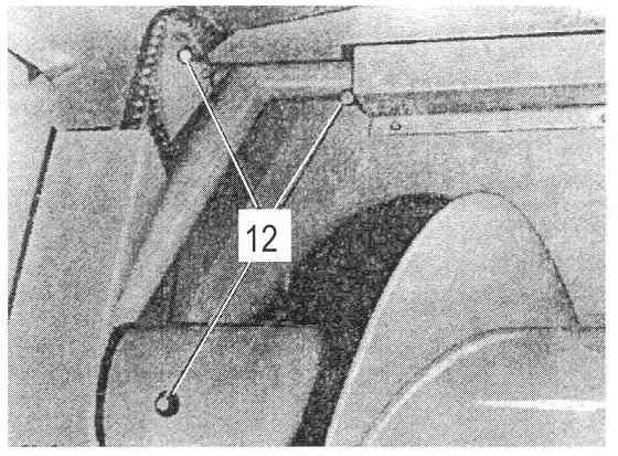
11 1 15. Do not wear unbuttoned, loose clothes with hanging or protruding parts which can be caught by rotating elements. 16. Never leave the baler with its drive switched on or with working tractor engine. 17. It is forbidden to transport people on the machine during its transportation and operation. 18. Prior to performing any operations connected with the pick-up baler it is necessary to switch the drive of the power transmission shaft, wait until the mechanisms of the baler stops rotating, switch off the tractor engine and remove the key from the ignition switch. 19. Before starting the machine and during its operation, the user must make sure that unauthorised persons, children or animals stay away from dangerous zones. 20. Operation of the baler can be started when normal rotating speed of the tractor power transmission shaft is reached. Nominal rotating speed of the tractor power transmission shaft is 540 rpm. 21. Do not exceed 600 rpm. 22. There should be no foreign objects on fields and meadows. 23. Stones and hard objects should be removed from fields and meadows. 24. Change from transport to operation position and vice versa of the baler should be performed only on horizontal and level surface. Point The front axle of the tractor (for the purpose of assuring steerability of the front tractor wheels) should be properly loaded. The minimum load of the front tractor axle must be 20% of the tractor weight. 26. Do not operate the baler on surfaces inclined more than 12% Notes and warnings concerning transportation of the baler 1. Be carefull when attaching the baler to the tractor. This action is especially dangerous. When the tractor moves back to the baler it is forbidden for anybody to be in the area between the baler and the mowing back tractor. 2. Check the attachment of the machine to the tractor. Attach the safety chain to a fixed element of the tractor suspension system. 3. During transportation, even on short distances, the machine must be set in its transport position (the baler reduces overall dimensions of the unit). 4. Check the drawbar securing in transport position. Correct drawbar securing eliminates accidental position change of the baler during its transportation on public roads. 5. While driving the unit on public roads, exercise particular caution and comply with the applicable road traffic regulations 6. For the time of transportation, a triangle warning plate should be installed on the baler. Fig.1 7. Before driving, the rear guide rail should be folded and the lighting installation of the baler should be connected with the external socket of the tractor electrical installation. Check the baler lights efficiency and the compatibility of the baler lights with the tractor lights. 10
12 Fig. 1 Location for installing a triangular warning plate 3.2. Notes and warnings concerning the baler servicing 1. Any repair, maintenance and adjusting works should be carried out only when the drive shaft and the tractor engine are switched off. Remove the key from the ignition switch. 2. It is forbidden to undertake any repairs or adjustment activities while the flywheel is moving. Warning: It takes about 40 seconds for the flywheel to stop rotating. 3. Exercise particular caution during any servicing, due to the danger of crushing, cutting or being caught by feeder elements such as: pick-up, spiral feeder and fork feeder. 4. While servicing the baler while in its lifted position, it is always necessary to protect the baler against falling down by use of proper supports. 5. While servicing the baler protective clothes, protective gloves should be used especially while replacing the piston knife and knotter knives. 6. While replacing the piston knife the flywheel should be immobilized. 7. It is necessary to use shear bolts, replace them with new ones of the same parameters. 8. You must not get in between the tractor and the machine until the unit is protected against movement by putting on the parking brake of the tractor or placing wedges under the driving wheels. 9. Cloggings and technological dirt in the baler should be removed only when the drive shaft and the tractor engine are switched off using a hook which is an equipment of the baler. 10. In the hydraulic system there is a very high pressure. When checking leaks use suitable protective means (for example cartboard cover) to avoid a risk of injury. In case of skin cut there is a danger of infection contact with a doctor. 11. Regularly inspect the hydraulic system (pipes, tubes, connectors) and exchange if they are worn out or broken paying particular attention to: Y Damages of the outer coating 11
13 1 Y Porosity of the outer coating Y Positioning under pressure and without pressure Y State of connections and seals Maximal period for using hydraulic pipes is 5 years (including storing period). When exchenging pay attention to use only such pipes which have the characteristics and quality complying the rules given by the machine s designer Fire fighting regulations 1. Pick-up balers usually operate in high fire hazard conditions (collecting dry, flammable materials at high temperatures). Therefore, special attention should be paid to the fire regulations when operating the balers. The tractor should be equipped with a large fire-extinguisher. 2. Before starting work, you should lubricate the baler in accordance with the lubrication plan, start the baler and make sure that there is not friction between the moving parts of the baler and the frame. Before going to the field, all detected sources of friction in the baler s mechanisms should be dealt with. 3. During short breaks in the baler's operation, the heating-up of the bearing mountings in the drive system should be controlled. The bearing mountings must not be allowed to heat up above 60 C. The operation of the baler in such conditions must be discontinued until the source of the heating up of bearings has been removed. 4. During breaks in the baler's operation, make sure that the picked-up material does not accumulate in large amounts, mainly around the shafts. The accumulated, particularly moist material which causes friction against the rollers should be removed only with the use of a hook when the tractor engine has been switched off. 5. Do not smoke or use open fires near the operating baler. 6. Do not use balers with damaged insulation of electric wires and exposed ends of these wires. 7. Repairs, particularly welding, may be performed only after the baler is carefully cleaned of the remains of the picked-up material. Before welding, the ducts of electric and hydraulic systems, bearings and bush housings made of plastic should be protected against any damage. User should remember that: the requirements with regard to work safety and hygiene as well as road traffic regulations and fire regulations must be adhered to. 12
14 4.The residual risk description The highest risk occurs when there are unauthorized persons (in particular children) and animals are close to the working machine. The risk increases if not enough attention is paid to the guidelines in this user manual and the warning stickers, in particular during: baler cleaning clogging removal correcting of pressed material during operation of the baler checking of mechanisms while the baler is operating carrying out regulations of the feeder, needles and piston adjustments when the baler is working Evaluating the residual risk during the baler operation If: the User Manual is carefully studied unauthorized persons are not allowed to approach the working baler closer than 3 m from the pick-up side children are not allowed to approach the working machine the baler is used in accordance with its designation only the operator may operate the baler (after careful study of the User Manual and safety regulations) periodical overhauls are carried out by trained persons the machine is secured during its repairs and daily maintenance, the user s risk should be excluded. Warning! A residual risk occurs if you do not read the described prohibitions and guidelines carefully enough and do not comply with them! 13

15 1 5.Warning stickers Warning stickers, which indicate the following dangers, are placed on the baler: Warning stickers must be always legible. If the stickers are no longer legible or are damaged, they can be purchased in the SIPMA SA sales outlets Before starting the machine you must familiarize with the user manual. 2. When regulating, maintaining, repairing and lubricating the machine, the tractor engine must be switched off. 3. Rotation direction (540 rpm). 4. Permanent manufacturer s number. 17. Do not touch the machine until all the machine parts stop moving. 18. Stand clear from the area of the joint hitches if the engine is on. 14


16 Danger of your hands getting caught by the auger. 6. Exercise caution sharp knives. 7. Company sticker type of the machine


17 1 8. For knotting use the twine in accordance with the recommendations and operate the knotter in compliance with the user manual. 9. Maximum transport speed. 10. Hook eyes for the machine loading. 11. Grease lubrication point. 12. Company plate Required tyre pressure


18 10.Hook eyes for the connection with tractor. 14.Hitching the baler to the tractor Do not get near the needle and knotter zone if the tractor engine is working and PTO shaft is switched on. 17


19 Danger of body injury by rotating spiral roller. 19.Stand clear from the area of the joint hitches when the engine is on. When a baler part with a sticker has been replaced, the same sticker should be placed on a new part. 18
20 6.Usage and operational servicing 6.1. Technical and operational data Machine length SIPMA PK4000 KOSTKA 4,85 m 4,9 m SIPMA PK4010 KOSTKA Machine width 2.5 m 2.5 m Height 1.55 m 1.60 m Weight 1555 kg 1560 kg Total pick-up width 1.78 m 1.78 m Pressing chamber width 460 mm 460 mm Pressing chamber height 400 mm 400 mm Bale length m m Number of piston strokes / minute Feed method Spiral roller + feeder Surface of inlet opening 2300 cm cm 2 Power demand over 30 kw (41 KM) Power receipt shaft rotations 540 rpm 540 rpm Twine sisal 4600tex tex polypropylene 2500tex -3300tex (strength min N) Declared value of noise level 85dB 85dB according to ISO Design and operating principle of the baler The conventional pick-up baler consists of a range of working units presented on Fig.2. Power is transmitted from the tractor by PTO drive shaft A to the overload oneway friction clutch B. This clutch protects the PTO drive shaft against damage and enables transmitting the rotations in compliance with the direction indicated by an arrow placed on the flywheel. Behind the clutch there is the flywheel C, which is the energy accumulator and an element of the overload friction clutch D. This clutch protects the baler components against damage when one of the components is blocked during machine operation. Next, power is transmitted to intersecting axis gear F, which reduces the rotational speed. 19
21 2 From the intersecting axis gear, power is transmitted to the following components: overview side view Fig. 2 Baler design diagram Pick-up Chain transmission F drives the clutch H with the jointed shaft of the pick-up I which transmits power to the pick-up K. Friction clutch H protects the jointed shaft I against damage. Pick-up, thanks to its flexible fingers with adjustable positions, takes harvest material and delivers it to the feeding unit i.e. spiral roller Z and feeder W. Piston Piston Ł is moved by means of crank G and connecting-rod J. The piston performs reciprocating movements on the rolls in the pressing chamber. On the piston, on the side of the feeder, a knife M is located which cooperates with the counter blade of the knife N, located on the side of the pressing chamber. After each feeding of material to the pressing chamber by the feeder, the piston, in its advance stroke, cuts off a portion of material and carries out initial pressing. Pressing is carried out as a result of pushing the material through the pressing chamber by means of the piston. Compaction rate depends on the resistance faced by the material in the pressing chamber, which is regulated by means of the hand wheels Y. Knotting unit is equipped with the switch Q 20
22 and bale regulation. At the moment when the preset bale length is achieved, the switch will switch on the knotting unit. The needles perform a swinging movement, wraps the bale with twine and give the twine to the knotting mechanism P. In the knotting mechanism the twine is knotted, cut off and prepared for creation of the next bale. The bale, which is knotted in two places, is pushed outside in the pressing direction by next material portions. The knotting process is described in further sections of this user manual First start-up First start-up of the BALER PK4000 and PK4010 is carried out by the Sales Representative or by the manufacturer and should be performed at the user s premises. First start-up is aimed at checking technical and functional condition of the machine and enabling the user to familiarize with the principles of proper operation of the machine and its working units as well as with safe operation principles. During first start-up the following should be checked: 1. Hitching of the machine with the tractor. 2. PTO drive shaft connection. 3. Setting the baler in its transport and working position. 4. Setting the pick-up. 5. Preparation of binding mechanisms for operation. 6. Adjustment of bale length. 7. Regulation of bale compaction rate. 8. Setting the metal plate chute. 9. Checking the regulation of the main working units. 10. Lubrication of the machine, in particular the cam and roller of the feeder. 11. Remove protective grease from the brake disc of the knotters shaft. 12.Tightening torques of thread connections Thread size [mm] Strength class Tightening torque [Nm] M M M M M M M16* M18*
.")
23 2 The machine does not require a special running-in period and may be operated from the very beginning on standard basis. However, it is recommended to operate the machine at lower compaction rate during first working period i.e. for about 20 hours, due to the fact that the pressing chamber surfaces are not smoothed which leads to strong braking of bales being pressed (loosen the hand wheels). In the warranty period no technical check-ups are planned. Required maintenance and adjustments should be made during the first start-up of the baler or they should be performed later by the user according to the user manual. Bale chute, which belongs to the special equipment, should be used after running-in of the pressing chamber Connecting the baler with the tractor The baler is hitched to the hook-type coupling of the tractor Fig.3 (information is given on the label located on the baler s drawbar) in the below specified sequence: Fig. 3 Label Hitching the baler 1. Lift the baler s drawbar to sufficient height by means of the drawbar support Fig.4a 2. Connect the baler with the tractor hook type coupling by means of a pin and secure it against sliding out. 3. Place a link of the protecting chain in the upper transport hitch, fix it with a pin and secure with a cotter pin. Fig. 4 Drawbar support in the position of hitching to the tractor. Fig. 5 Drawbar support in the position of operation and transport. 22
24 4. Assemble the PTO drive shaft to the tractor drive output shaft and the baler drive input shaft (see section 6.3.2) 5. Connect the baler s hydraulic duct, equipped with quick disconnecting coupling, with the socket of tractor hydraulic system (applies to PK4010 baler) Assembling the PTO drive shaft The machine can be operated efficiently and safely only if proper PTO drive shaft, equipped with complete cover, is used for driving the machine. It is forbidden to assemble and operate the shaft with a damaged cover. The baler is equipped with a special PTO drive shaft which, due to its length, transmits a torque of 540Nm (L min =1020mm; L max =1430mm ) and the overload one-way clutch which is set for the torque of 900Nm. Assembling of the PTO drive shaft should be carried out only after the tractor drive output shaft has been switched off and tractor engine stopped. Assembly should be carried out in the following sequence. 1. Slide the end of the PTO drive shaft on the tractor drive output shaft and protect with snap fasteners. 2. Check if the snap fasteners securely protect shaft ends. 3. Fix the shaft cover chain, one on the tractor element side, another one on the baler drawbar side. 4. The PTO drive shaft should be connected with the tractor drive output shaft also during transport of the machine. After disconnecting the baler from the tractor the PTO drive shaft end should be placed on the bracket fixed to the drawbar. In order to assure proper durability of the PTO drive shaft, the drive should be switched off on sharp corners! Hydraulic pipes The hydraulic pipe for lifting the pick-up, which is connected to the tractor during collection of material, is installed on the baler. The pipe is equipped with quick disconnect couplings M22x1.5. In the case when the tractor is equipped with a different quick disconnect coupling type than the couplings on the pipe, the pipe couplings should be replaced with the ones which match the tractor couplings. Thread connections should be sealed. 23
25 2 While changing the quick-disconnecting coupling, the hose ends and the couplings should be protected against any contamination, otherwise the tractor or the hydraulic system of the baler may be damaged. The feed hose of the pick-up cylinders, which has a quick-disconnect coupling, should be permenantly fixed at the outlet of the tractor hydraulic system. The pick-up operation should be checked by lifting and lowering the pick-up several times. Lifting and lowering of the pick-up assures air removal from the whole hydraulic system. 1. Pressure of the hydraulic oil can be so high that it may cause serious injuries in case of oil leakage. Allowable hydraulic oil pressure is 16MPa 2. Immediately contact a physician in case of an accident. Lack of immediate medical assistance may lead to serious skin infection. 3. Before disconnecting the hydraulic pipes and connections, hydraulic oil pressure should be completely reduced. When hydraulic oil pressure is increased again, it is necessary to check tightening of thread connections and inspect the installation, rigid ducts and hoses for damage. During many years of its operation, the hydraulic system is subjected to the influence of continuous pressure, temperature and ultraviolet radiation which may affect the components in time. Currently offered hydraulic hoses have a production date embossed on them which enables specifying their usage period. Legal regulations as well as practical experience indicate that hoses should be replaced every 6 years. Fig. 6 Diagram of the hydraulic system in PK 4000 and PK hydraulic cylinder, 2 - quick-disconnecting coupling of the pick-up Fig. 7 Diagram of the hydraulic system in PK quick-disconnecting coupling, 2 - rotating divider, 3 - hydraulic lock, 4 - two way cylinder for drawbar movement, 5 - one way cylinder for pick-up lift. Position PD in the divider enables simultaneous pick-up lift and moving the drawbar to the transport position Setting the baler in transport and operation positions (PK 4000) In order to move the baler drawbar from the transport position to the operation position, it is necessary to unlock the drawbar by means of a rope. 24
26 Fig. 8 Drawbar locking mechanism Next, turn the tractor wheels to the left (Fig.8) and drive forward until the locking pin slides into the baler s hole. During unlocking of the drawbar by means of a rope, the right driving wheel of the machine is simultaneously blocked, which facilitates moving of the drawbar. In order to move the drawbar from the operation position to the transport position, the following activities should be carried out: - place the pick-up as high as possible and secure it with a chain - fold the steel plate chute and secure it with the catch - fold the rear bale slide (if it is installed) and secure it Fig. 9 Setting the baler into operation position - install a triangle warning plate in the rear holder of the baler 25
27 2 - turn the front tractor wheels to the right (Fig. 10). Unlock the drawbar by means of a rope and drive backwards until the drawbar locking pin slides into the transport hole of the baler body. Fig. 10 Setting the baler into transport position Setting the baler in transport and operation positions (PK 4011) In order to move the baler drawbar from the transport position to the operation position, it is necessary to unlock the drawbar, set the lever of the hydraulic divider into the position D and start the cylinder 2 from the tractor Fig. 11 Side view of the hydraulic system in PK 4011 In order to move the baler drawbar from the operation position to the transport position do the same as above changing only the direction of the oil flow in the tractor. 26
28 Fig. 12 Overview of the hydraulic system in PK 4011 (operation position) After disconnecting the baler from the tractor, the hydraulic hose end should be protected against any contamination. Fig. 13 Overview of the hydraulic system in PK 4011 (transport position) After hitching the baler to the tractor, the jack stand should be moved to the horizontal position and secured with a pin Setting the pick-up Retainer placed over the pick-up doses the material and directs the material under the spiral feeder. The retainer can be set in three positions (depending on type of the material being picked-up), for example; 27
29 2 - for wilted grass and hay - lower the pick-up (smaller clearance) - for straw - lift the pick-up. Fig. 14 Setting the retainer Finger ends of the retainer should be placed at the height of the horizontal axis of the spiral roller. In order to lift the retainer, pull out the pin 1 and turn it by 90º, move the retainer to the right and lift it. Fig. 15 Lifting and lowering of the pick-up In order to lift the pick-up to required height, turn the lever several times at the same angle A. In order to lower the pick-up, turn the lever several times only at a small angle B. Lifting and lowering of the pick-up of PK4010 baler is carried out by means of a hydraulic cylinder controlled from the tractor hydraulic system. 28


30 Preparation of knotting mechanism for operation The knotting system of the baler is designed for knotting only below specified twines: -sisal twine 4600tex-6700tex -polypropylene twine 500m/kg-330m/kg which has the strength of 1000N-1100N The above specified twines have enough strength and thickness to assure proper operation of the knotting mechanisms. Using twines other than the above-specified always leads to serious defects of the knotting mechanisms. The twine box can hold 10 twine coils. Partition walls Fig. 16 should be removed when lower twine chambers are being loaded. Fig. 16 Twine box During twine threading, the protectione lever S must be set in the position STOP (Fig.12 and Fig.13) Fig. 17 Protection lever Fig. 18 Label of needles blockage Figures 19, 20, 21 show proper method of connecting the twine coils and knotting twine ends depending on the twine type. Figure 18 shows proper twine threading. 29

31 3 During twine coil connecting, internal twine end must be pulled out from the hole on this side where knots are not created during pulling out the twine. Fig. 19 Twine coils connecting method Fig. 20 Flat knot for sisal twine Fig. 21 Knot for polypropylene twine Twine which is pulled out of the twine coil centre should be successively threaded through: catch 1 (Fig. 22), tensioner 2 and twine guide-eyes 3, 4 (collectively) and 5. Length of the spring L (Fig. 22) should be regulated depending on twine type and compaction rate. After connecting the twine coils and threading the needles, the twine should be inserted (by the needles) to the knotters, by performing the following activities: - rotate the disc G (Fig. 23) until the arm of J switch moves to upper position, which will activate the drive of knotting mechanisms. Next, turn the flywheel manually (in the direction indicated by an arrow) in order to insert the twine by the needles to the knotters. When the twines are already clamped between the disks of the catchers and kneaders in both knotters, the flywheel should be still rotated until the moment when the knotting mechanisms perform a full working cycle, i.e. when the needles and switches come back to the initial position. Cut off twine pieces with single knots should be removed from the knotters fingers. 30
.")

32 Twine tightening is regulated by the push button 2. Twine should be tightened in such a way as not to make knots during return of the needles. Fig. 22 Twine threading Fig. 23 Bale length regulating mechanism Adjusting the bale length Bale length is regulated steplessly in the range of m by means of movable buffer H located on J arm (Fig. 23). When the buffer H is moved upwards, the bale length is increased. In order to assure uniform bale length, tighten the pressing screw firmly to prevent undesirable buffer movement Regulating the bale compaction rate The higher resistance in the pressing chamber, the more compacted the material subjected to pressing and the higher the compaction rate. Compaction rate is regulated steplessly by means of hand wheels K (Fig. 24). When the hand wheels are rotated to 31

33 3 the right the pressing rate is increased. After longer breaks in operation of the machine, it is necessary to loosen the hand wheels before restarting the operation and retighten the hand wheels after making the first bales. If humidity of material changes during pressing process it is necessary to make the setting correction by regulating the hand wheels. Fig. 24 Compaction rate regulation Adjusting the metal plate chute The metal plate chute is used for placing bales on the field (Fig.25) This working method of the machine allows the achieving of the highest efficiency, because there are no other efficiency limiting factors. Fig. 25 Metal plate chute 32

34 For the purpose of working on slopes and in case of collecting material from narrowly spaced material rolls, a half of the metal plate chute may be removed (Fig.26). In such a case bales will be placed to the side of the baler. Fig. 26 Folded chute Assembling the rear bale skid ramp The below specified activities must be performed by at least 2 people. The rear bale skid ramp is assembled by means of two plates and bolts M12x25 fixed to the pressing chamber and may remain permanently fixed to the machine. In the transport position the skid ramp is folded and fixed to the holder with a snap fastener (Fig.27). In the operation position the bale skid ramp is unfolded and set by means of a chain and a catch located on the pressing chamber (Fig.28) 33
35 3 Fig. 27 Transport position of the bale slide Fig. 28 Operation position of the bale slide The bale skid ramp should be positioned in such a way as to achieve a bale feeding height of 2.3 m to 2.8 m. The bale skid ramp should be suspended freely on a chain and should not be supported on the trailer side wall because while turning and on very uneven surfaces the trailer or the skid ramp may be damaged. When the bale skid ramp is used, the springs should be loosened i.e. the compaction rate should be reduced for bales, because they are additionally pressed by the bales located on the skid ramp. The rear drawbar is used for hitching a trailer to the baler and it should be always assembled together with the bale skid ramp. 34
36 Two axle trailers of allowable total weight up to 5.6t may be hitched to the baler. The bale skid ramp is fixed under the pressing chamber by M12x35 bolts. It has regulated length which allows hitching various trailers. Stretcher bar A Fig. 29 is an additional reinforcement which is assembled together with the rear drawbar. Fig. 29 Rear drawbar and the stretcher bar All the elements of the bale skid ramp are presented in the catalogue of parts in the table 20. In case of difficult soil conditions it is recommended to use tyres for the following wheels: -wheel next to the pressing chamber 11.5x15-6PR-AM4-1 -wheel on the side of the pick-up 10x15-6PR-AM4-1 snap-axis =

37 Baler operation It is recommended to operate the baler at its nominal working speed while collecting medium size swaths. The working speed should be adjusted in such a way as to avoid clogging of the baler. The working speed must not exceed 8 km/h. Rotation speed of the tractor transmission shaft must be 540 rpm regardless of the driving speed. Reduction of the rotation speed results in dangerous clogging of the baler. A balanced crank-piston system is applied in the balers to reduce vibrations of the baler during its operation, decreasing power consumption, improving working conditions of the operators and reducing wear of parts. While operating the baler, special attention should be paid to checking the reliability of bolt connections 1 and 2 (Fig. 26) of the counterweight with arms and the crank, particularly in initial stage of operation. In case of any disassembling of the crank, the counterweight should be assembled in such a way as to assure that there is no friction between the plate and cooperating parts of the baler i.e. connecting -rod and chain of the pick-up drive. The ends of the pick-up fingers should not touch the ground during operation because harvest material may be contaminated. Gauge wheel of the pick-up is already properly positioned. The distance between the pick-up fingers and the ground is changed by changing the position of the gauge wheel (Fig.30). Fig. 30 Regulation of pick-up wheel Fig. 31 Balancing system Pressure of the gauge wheel on the ground is regulated by means of the relief spring Fig.32 36

38 Fig. 32 Relief spring of the pick-up Pay attention to the PTO drive shaft while taking sharp turns. In order to assure proper durability of the shaft the drive should be switched off while taking sharp turns! 7.Technical service 7.1. Regulation of the main operating units In order to carry out the proper setting of operating units during repairs or inspection works it is necessary to check the following: 1. Setting of the piston with regard to the feeder. 2. Setting of the knotter shaft clutch with regard to the transmission shaft. 3. Setting of the knotting needles. 4. Setting of the needles with regard to the piston. 5. Resetting of the needles with regard to the piston. 6. Setting of the needles with regard to the knotters. 7. Setting of the twine retainers with regard to the needles. 8. Setting of the piston and the knives. 37
39 Setting the piston with regard to the feeder Rotating the flywheel, move the piston to the position shown by Fig.33 Type A B mm mm C PK4000 KOSTKA PK4010 KOSTKA PK4011 KOSTKA Fig. 33 Setting of the piston with regard to the feeder If the fingers of the feeder are positioned vertically downwards (C=90º), the dimension A, from the face surface of the piston to rear edge of the side wall of the feeder chamber, is mm or the face surface of the piston is visible in the hole on the side wall of the pressing chamber. Next, with the fingers of the feeder positioned vertically (C=90º), set the dimension B, measured from the rear wall of the feeder chamber to the point marked on the gear wheel, at 70 mm. Assemble the chain in such a way as to assure tightening of its lower part. After fastening the chain of main drive, unlock the tightener, rotate the flywheel several times and check the dimension mm Setting the knotter shaft clutch with regard to the transmission shaft During assembly of the knotters, both gear wheels (gear wheel and cam disc) should be positioned in such a way as to assure that the marked tooth under the key in the gear wheel enters the marked notch of the cam disc wheel (Fig.33). 38
40 Setting the knotting needles In their rest position, the ends of the needles should be located at the position D = 60-75mm Fig.34 with regard to lower surface of the chamber bottom. Corrections can be made by screwing in or screwing out the rocker string of the needles. Fig. 34 Setting of the needles Setting the needles with regard to the piston Setting should be carried out in such away as to assure upwards movement of the needles in the grooves of the piston. The tops of the needles must enter the grooves at a distance of E = mm behind the tops (teeth) of the piston Fig.35. If this condition is not fulfilled, the previous settings must have been carried out in an incorrect way. In such a situation the synchronization must be checked and corrected according to the specified sequence. If, after checking, the dimension is still incorrect, it is necessary to make corrections (changes) of the chain wheel position on the transmission shaft of the feeder (3 key grooves in the hub). The needles will not be damaged during knotting operation only if dimension E is maintained Resetting the needle with regard to the piston Switch on the mechanisms (for this purpose, rotate the switch star) and rotate the flywheel in the direction indicated by an arrow, until the needles are located at the height of the chamber bottom, check the dimension E Fig.35. If the setting is to be corrected, it is necessary to disassemble the main drive chain and set it in such a way as to assure that the clutch disk of the knotters S is not out of gear Fig

41 4 Fig. 35 Setting of the needle with regard to the piston Insert the protecting element of the connecting link of the chain in the direction opposite to the chain movement direction, on the side facing the gear, and next, check dimension E and synchronization of other units, rotating the flywheel in the direction indicated by the arrow. Fig. 36 Resetting of the needles with regard to the piston 40
42 Setting the needles against the knotters The needles should be set in such a way as to assure that they lightly touch the knotter body in points X and move in the interval 4-6 above the catcher Fig.37. The distance between the needles and catcher disks can be increased by loosening A bolts and tightening bolt B. The distance can be decreased by loosening bolts B and tightening bolts A Fig.37. Distance between the needles and the catcher Needles regulation Fig. 37 Resetting of the needles against the catcher Setting the twine holders against the needles In order to set the twine holders, set the knotting mechanisms and rotate the flywheel in the direction indicated by the arrow, until the ends of the needles in their return movement, are located over the table of the knotting mechanisms. The distance between the holder N and the internal edge of the needle should be 3-5mm Fig.38. Regulation of the twine holder can be performed in the following way; loosen the bolt P, move the holders N and secure them again by striking with a centre punch. In the rest position, the sharp end of the twine holder will be placed again at the distance of about 50±2mm from the opposite edge of the needle slot in the table of the knotting mechanisms. Corrections can be made by screwing in or screwing out of string Z. In order to avoid exceeding the dead centre by both twine holders N, the adjusting screw S is located on part of the steering shaft. The distance between the adjusting screw S and the buffer T should be approximately 1mm at the moment when the steering roll R is located at the highest point of the cam race of the knotter drive disk. 41
43 4 Fig. 38 Setting the twine holders 42
44 Setting the piston and the knives Fig. 39 Setting of the piston with regard to the chamber Fix the guide rail A Fig.39. in parallel to the chamber bottom at the distance of D=196mm. Move the piston with a loosened knife the previous dead centre and move the loosened guide rail C in parallel to the side in such a way as to assure that the guide rolls J adhere to the guide rail C on one side and to the chamber wall on the other side. Tighten firmly the front screws E. Next, move the piston to the rear dead centre and also set properly the guide rail C in this position. Tighten firmly all bolts E. Move front upper guide roll F located in a skew groove closely to the upper guide G. Adjust the rail R to the roll S by means of T bolts with minimum clearance of 0.5mm. Cutting slot S between the blades of the knives (piston L and pressing chamber M) should be mm. In such a situation the cutting strength has the minimum value Fig.40. The knives should always be sharp. The knife of chamber M may be used as a double sided knife. During sharpening and replacing of the piston knife, the flywheel should be immobilized. 43


45 4 Fig. 40 Setting of the cutting slot between the knives Regulating the main chain tensioner The main driving chain is tightened by the tensioner wheel Fig.41, which is pulled out by a spring and because of this the tension value is constant. Fig. 41 Chain tensioner 44
.")
46 The return buffer R, placed on the arm of the tightener wheel A, is used in order to prevent the return of the tensioner wheel. The return buffer must be fixed by screws to the arm in such a way as to assure possibility of return movement (chain loosening). In the initial stage of the machine operation, when the chain is being extended, it is necessary to control and correct the return buffer setting. Such activity is aimed at preventing the chain skipping during possible reverse rotation of the machine mechanisms. Wet straw and hay must not be pressed due to the possibility of a drive system defect, danger of the baler clogging or breaking of the needles. Before any activity connected with the removal of clogging, the tractor engine should be switched off. The tractor connected to the machine should be secured against possible start-up by any unauthorized persons Recoil mechanism The return buffers R Fig. 42, which are pressed by springs and used for holding pressed material, must be always movable. During working stroke of the piston, the return buffers are hidden and when the piston is withdrawn, they enter the pressing chamber again. Immobilizing of the buffer results in pressure of straw on the needles, which consequently might be broken. Fig. 42 Recoil mechanism 45
47 Regulation and adjustment of the feeder In order to obtain straight bales with different material collection conditions, adjusting lever S is used to regulate steplessly. Additionally, finger Z of the feeder may be fixed by bolts N in four different positions: -bale curving to the left Fig.43; screw out adjusting lever S, increasing X value in this way or lower finger Z -bale curving to the right; screw in adjusting lever S, decreasing X value in this way or lift finger Z. Fig. 43 Regulation of the feeder. Normal distance X between the rotation centres is 640mm. After setting the X distance, the P pin should be secured once more against falling out. Additionally, rotating the flywheel of the machine, check sufficient distance between ends of the piston and fingers of the feeder. Automatic mechanism M in the the feeder, protects the feeding fingers against overloading. When overloading occurs the automatic mechanism causes backwards deflection of the feeder s fingers and switching off is accompanied by a loud crack. If, after hearing this signal, the tractor driver stops the machine for a short time, without switching off the baler drive, the automatically returning fingers of the feeder will remove the clogging. Spiral roller will automatically adjust to all material collection 46

48 conditions and amounts of transported material. The driving chain of the spiral roller is automatically tightened Pick-up shaft clutch The friction and overrunning clutch of the PTO drive shaft Fig.44 is adjusted to 900Nm torque. After longer idling time of the machine, for example during winter time, loosen the 6 nuts which press the disc, rotate the clutch for a short time and tighten the nuts to their previous position and secure them with lock-nuts. Fig. 44 The overload, one-way clutch Flywheel clutch Slip moment of the flywheel clutch Fig.40, amounting to Nm, is achieved by tightening the disk springs C with a nut A, until they are squeezed to a flat position. A damaged clutch facing should be replaced. In case of replacement, the clutch facing B should operate with a newly adjusted torque of Nm in order to completely run-in the clutch facing surface. Next, loosen the nut A, clean the grooves of the clutch facing, retighten the nut and secure it. The clutch is ready for usage. After longer idling time of the machine, for example during winter time, release the clutch before next usage (separate friction disks) by pulling away the flywheel from the clutch disk with impulse motions using a lever applied to several places on the circumference. 47
49 4 Fig. 45 Flywheel Pick-up clutch The baler is equipped with the overload friction clutch in order to avoid damages of the pick-up during operation in unfavourable conditions. The clutch is adjusted to the torque of 450±50Nm. During replacement of the clutch facing, run-in the clutch 10 times at 5 sec. intervals at the torque of 150Nm and 86 rpm Feeder clutch Deflection torque of the feeder s forks is set at the manufacturing plant and is Nm. This torque must not be regulated by the machine user Protection of the needles A shear bolt in the pull rod of the needle rocker is used for protecting the needles from breaking. After shearing of the bolt, remove defect cause, install a new needle of strength class 8.8 and carry out regulation of the needles. 48

50 Adjusting the knotter shaft brake The brake of shaft B Fig.46 is properly adjusted when the springs F are clamped to the length L=23-24 mm. Fig. 46 Knotter shaft brake 7.2. Knotter - operation Figures from 47 to 52 show specific operation stages of the knotters and general twine flow. Fig.47 The end of the twine and its remains are tightened by means of the kneader 1 in a groove of the catcher 2. From here, the twine is carried above the groove b and the jaw 3 of the finger of the knotter through the arm guide 4 and further over the top of the needle and the twine tightener to the twine coil box. The twine wraps three sides of the bale. 49

 both twines are clamped in the groove of the catcher.")

51 5 Fig.48 Fig.49 Fig.50 After operation starting the needle lays the twine around the fourth side of the pressed bale and carries it further over clamped jaw of the finger 3 to open groove b of the catcher 2. After operation starting the needle lays the twine around the fourth side of the pressed bale and carries it further over clamped jaw of the finger 3 to open groove b of the catcher 2. At the moment when the needle and the piston reach their position (dead position) both twines are clamped in the groove of the catcher. The remaining part of the twine in the groove is released as a result the catcher rotation. When both twines are clamped in the groove b, the knotter s finger rotates and makes a loop around itself. After rotation by about 180º the roller of the jaw of the knotter s finger drives on the cam of the knotter s body, which results in opening the jaw of the knotter's finger. In the mean time, the catcher rotates so far that, after about 270ºrotation of the knotter s finger, two twines clamped in the knotter are positioned at the proper height and slide between the jaw and the knotter s finger. After about 340º rotation of the knotter s finger the cam reaches its end. The jaw of the knotter's finger is closed by the holder which is released by the spring and both twines are held in the jaw. 50


52 Fig.51 Fig.52 After a further 360º rotation of the knotter s finger, the cam is again placed in the rest position, the catcher ends its rotation by 90º and opened groove c is placed between rear half of the cleaner and rear nose of the twine holder. Both edges assure good guiding of the twine. The second half of the cleaner cleans the groove off the twine waste ends, if they do not fall out by themselves. The twine which is jammed in the groove b is inserted to the groove c by the returning needle. The knife lever 4 deflects forward and cuts with its blade 5 both twines which are jammed in the jaw of the knotter s finger and in the catcher. The scraper 6 on knife lever 4 scrapes the loop laid around the knotter s finger and carries the loop through the twine ends which are jammed in the jaw and in the knotter's finger, creating a knot in this way. With further rotation of the knife lever the knot is scraped from the knotter s finger and jammed ends of the twine are pulled out from the jaw and the knotter s finger. At the same time the needle is withdrawn further. For the time being, the needle has put aside the twine on the arm 7 of the knife lever 4 which is tilted forward, in order to protect the twine from being scraped by twine loop from the knotter s finger. Only after the knotting operation is completed, the knife lever is withdrawn and the twine is slid off the lever s arm 7 and slides to the twine guide (on the knife lever). The twine guide on the knife lever is shaped in such a way that the twine falls down exactly on the jaw of the knotter s finger. The needle is withdrawn to the lower dead centre and a next piston stroke begins. 51

53 Kneader The kneader 1 Fig.53 is tightened by pressure spring 2 regulated by means of a nut 3. In case of excessive pressure of the kneader the knot remains caught on the knotter s finger and the twine is broken. Too loose a setting causes loose knots. Fig Twine catcher The groove of the catcher 4 Fig.49 must be located between the rear nose of the twine kneader 5 and the rear half of the cleaner 6 in order to assure precise lying of the twine. At least two knotting cycles must be carried out in order to check proper location of the groove. Both guiding edges of the rear noses of the twine kneader must then enter 1-2 mm to the groove and maintain the dimension of 4mm between the edge of the catcher s groove and the kneader s nose. In order to set the catcher, it is necessary to release the nut 7 on the worm shaft. The worm is released by light striking of the shaft face. Proper location of the groove may be obtained by proper fixing of the worm with the nut. However, the worm may be fixed with the nut only when there is no twine in the twine holder. Pressure strength of the twine in the catcher is regulated by hexagonal screw 8, which tightens the kneader through the spring and the lever 9 Fig.55. The screw of the lever is secured with a lock-nut. The kneader should clamp the twine only to such a degree as to assure that the twine is not pulled out from the kneader during the knotting operation. As a result of excessive clamping the twine will spilt. The clamping force should be adjusted in proportion to bale weight increase or bale humidity. Type and humidity of the pressed material require various settings, which, if it is necessary, should be adjusted in working conditions. 52


54 4 mm Fig.54 Fig.55 53


55 Knife arm The knife arm 1 has three following tasks: -cutting of the twine between the catcher and the knotter s finger, -pulling off a loop or a ready knot, -guiding of the twine. Fig Operation inspection. The knife lever should be adjusted in such a way as to assure free rotation of the knotter s finger. Scrapping part the knife lever 2 should touch the ridge of the knotter s finger. The stroke of the knife lever should assure reliable scrapping of a knot from the knotter s finger. In the dead centre of the knife lever, the scrapping part should be located 10-12mm from the top of the knotter s finger. The distance should be checked by switching on the drive of the knotters, carrying out one manual knotting and specifying the biggest spacing according to Fig.57. Fig.57 In order to carry out required setting of the lever it is necessary to adjust the fixing of the knotter to the table of the knotting mechanism (fixing pins H with a spring plug) and tilt the knotter s body K upwards Fig.55. Now, the knife lever can be adjusted by striking it with a hammer or using a special wrench Fig.58. The knife lever, due to the fact that it guides the twine, must have all its edges rounded as well as smooth surfaces, especially in the place marked with a circle on the Fig.59. The knife, as a 54
56 replaceable part, is fixed to the knife lever by means of two hexagonal screws. Special attention should be paid to the condition of the knife blade. If twine ends are cut unevenly and are shreded, it is necessary to sharpen the knife (carry out knife sharpening on average every 50 working hours). Fig.59 Fig.58 Fig Daily maintenance 1. Lubricate in accordance with the lubrication instruction of the baler and PTO drive shaft. 2. Check the setting of the knotter knife lever, adjust in cases where the lever does not touch the finger. 3. Check tension of the chains. 4. After each operating day, it is necessary to remove bales from the pressing chamber; otherwise the material swollen during the night will make it difficult to start the baler the next day. 55
57 Lubrication Regular lubrication of the baler mechanisms according to the below specified recommendations is crucial for durability of the machine Lubrication safety Lubrication of the baler may be carried out only after the machine drive and the tractor engine have been switched off! The tractor connected to the machine which is being lubricated should be secured against possible start-up of the tractor by unauthorized persons Lubrication intervals Lubricate the rolling bearings of the following units every 90 working hours: feeder steering rod feeder bearing needle rocker knotter disc resistance washers piston pin bearing drive chain tensioner jointed shaft of the pick-up drive drive worm Lubricate the rolling bearings of the following units every 12 working hours: jointed shaft knotter shaft clutch knotters needle string Lubricate the driving wheel bearings once a year. Check oil level in the transmission once a year Types of grease All lubrication points, except the final drive, lubricate with grease ŁT-43. Add oil Hipol 15 to the final drive. 56
![7.4.4. Lubrication table Table 1 Lublication Figure marking Lubrication place Number of lubrication points Lubricant Lubrication frequency [ h ] 1 Jointed shaft 3 Grease 12 ŁT-43 2 Feeder steering 2](/docs-images/73/68781018/images/58-0.jpg "As above 90 3 Feeder bearing 5 As above 90 4 Knotter shaft clutch 1 As above 12 5 Knotters 14 As above 12 6 Needle string 2 As above 12 7 Needle rocker 2 As above 90 8 Knotter disc resistance 2 As")
58 Lubrication table Table 1 Lublication Figure marking Lubrication place Number of lubrication points Lubricant Lubrication frequency [ h ] 1 Jointed shaft 3 Grease 12 ŁT-43 2 Feeder steering 2 As above 90 3 Feeder bearing 5 As above 90 4 Knotter shaft clutch 1 As above 12 5 Knotters 14 As above 12 6 Needle string 2 As above 12 7 Needle rocker 2 As above 90 8 Knotter disc resistance 2 As above 90 washers 9 Piston pin bearing 1 As above Main chain tensioner 1 As above Jointed shaft of the pick-up 2 As above 90 drive 12 Drive worm 3 As above Driving wheel bearing 2 As above Once a year 14 Final drive 1 * Once a year Add only Hypol 15 oil. Fill up to the inspection bolt. Fig.61 Fig.62 57


59 5 Fig.63 Fig.64 Fig.65 58

60 Fig Details concerning lubrication The greaser should be used for lubrication of bearings of the working units. Grease ŁT-43 should be forced into grease nipples until fresh grease flows out through the holes in bearing covers. The above specified recommendations should be adhered to exactly. 59
INSTRUCTION MANUAL. Fixed Chamber Baler SIPMA PS 1510 FARMA SIPMA PS 1210 CLASSIC SIPMA PS 1211 FARMA PLUS SIPMA PS 1221 FARMA PLUS
 SIPMA S.A. ul. Budowlana 26 20-469 Lublin, Poland tel. (+48) 81 74 45 071 www.sipma.pl INSTRUCTION MANUAL Fixed Chamber Baler SIPMA PS 1510 FARMA SIPMA PS 1210 CLASSIC SIPMA PS 1211 FARMA PLUS SIPMA PS
Operator s Manual. Model: TX31 Mini Round Baler. ibexequipment.com IBEX
 Operator s Manual Model: T31 Mini Round Baler 2018-07.1 ibexequipment.com 833-888-IBE Contents 1 Introduction... 1 1.1 Conditions of Use... 1 1.2 Machine Description... 1 1.2.1 Pickup Lift Lever and Lock
ENGINEER S MANUAL No.01
 1-NEEDLE, UNISON FEED, LOCKSTITCH MACHINE (AUTOMATIC LUBRICATION) LU-1510 1-NEEDLE, UNISON FEED, LOCKSTITCH MACHINE WITH AUTOMATIC THREAD TRIMMER (AUTOMATIC LUBRICATION) LU-1510-7 1-NEEDLE, UNISON FEED,
Operators Manual. Issue 1.2. Conditioner 2500
 Issue 1.2 Conditioner 2500 Operators Manual Ensure that everybody that operates the machine reads and fully understands this manual prior to operation. This manual is considered a permanent part of the
Technical Data. Name: ERIKA Automat fully automatic machine to divide and to round dough pieces of the same size
 AUTOMAT MANUAL 1 Technical Data Name: ERIKA Automat fully automatic machine to divide and to round dough pieces of the same size Type Divisions Dough Portions (in ounces) Plate Nos. 3 30 1.0 3.5 #35 4/40A
Hakki Pilke Raven spare parts manual
 1 ENGLISH Hakki Pilke Raven spare parts manual Valimotie 1, FI-85800 Haapajärvi, FINLAND Tel. +358 8 772 7300, Fax +358 8 772 732 info@maaselankone.fi, www.maaselankone.fi 2 Table of contents 1 Upper section
HD Kompakt Service Manual
 HD Kompakt Service Manual English 5.906-583.0 Rev. 00 (08/13) 1 1 Contents 1 Contents.................................................... 2 2 Preface.....................................................
IMPORTANT SAFETY INSTRUCTIONS
 CONTENTS 1.SPECIFICATIONS... 1 2.INSTALLATION... 1 3.INSTALLATION OF THE SYNCHRONIZER... 2 4.ASSEMBLY OF HAND WHEEL... 2 5.INSTALLATION OF HAND WHEEL... 2 6.INSTALLING THE BELT COVER... 3 7.ADJUSTING THE
USER S MANUAL ATH WH220
 USER S MANUAL ATH WH220 INDEX INTRODUCTION... - 3 - General information s... - 3 - Description of pneumatic jack... - 4 - Operation of jack... - 5 - Technical data... - 6 - Dimension drawing... - 6 - INSTALLATION...
OPERATING MANUAL ORWAK March 2005 PUBL. NO Edition 4
 GB OPERATING MANUAL ORWAK 3400 March 2005 PUBL. NO 4869057-00 Edition 4 English TABLE OF CONTENTS Safety... 82 Operating instructions... 93 Technical specifications. 104 Dimensional drawing... 104 Transport...
DEUTSCH Bio-Master Bio-Max
 DEUTSCH D 8217-3029-02 Bio-Master Bio-Max SVENSKA S 4. 2. 1. 3. 4. 5. 3 S SVENSKA 7. 6. 8. 9. 10. 4 SVENSKA S 11. 12. 4. 13. 4. 15. 14. 5 GB ENGLISH SAFETY PRECAUTIONS GENERAL This symbol means WARNING.
EAGLE 2000B EAGLE 2000BE EAGLE 2000EBT MUST READ MANUAL PRIOR TO INSTALLING MACHINE
 EAGLE 2000B EAGLE 2000BE EAGLE 2000EBT MUST READ MANUAL PRIOR TO INSTALLING MACHINE Contents 1 Machine Safety Information 3 1.5 Safety Precautions Prior to Operating Machine 6 2 Machine Installation 7
PLC-1700 Series PLC-1710, , 1760, , 1760L
 Post-bed, Unison-feed, Lockstitch Machine PLC-1700 Series PLC-1710, 1710-7, 1760, 1760-7, 1760L ENGINEER S MANUAL 40040656 No.E372-00 Introduction This Engineer s Manual is for technical service engineers.
User Manual GV25 GV35 GV702. Company information: Original instructions GV12066 (1)
") User Manual Original instructions GV25 GV35 GV702 Company information: www.vipercleaning.eu info-eu@vipercleaning.com GV12066 (1) 2012-04-10 USER MANUAL ENGLISH TABLE OF CONTENTS Introduction... 4 Manual
User Manual Original instructions GV25 GV35 GV702 Company information: www.vipercleaning.eu info-eu@vipercleaning.com GV12066 (1) 2012-04-10 USER MANUAL ENGLISH TABLE OF CONTENTS Introduction... 4 Manual
Grain crusher Universal. Purpose: This machine is designed for the crushing of grain in agricultural operation.
 Grain crusher Universal. Purpose: This machine is designed for the crushing of grain in agricultural operation. Operating instructions and parts catalogue This grain crusher provides you with a machine
JASOPELS ROTATING FLESHING MACHINE 1-BEAM
 USER MANUAL JASOPELS ROTATING FLESHING MACHINE 1-BEAM ITEM NO. 32200067 Our quality Your choice 2 www.jasopels.com TABLE OF CONTENTS About this document... 3 Declaration of Conformity... 6 Safety... 6
SAFETY AND OPERATING MANUAL
 SAFETY AND OPERATING MANUAL 2 General Safety Warnings WARNING: Read all safety warnings and all instructions. Failure to follow the warnings and instructions may result in electric shock, fire and/or serious
OPERATOR S MANUAL. For BURLY ATTACHMENTS
 OPERATOR S MANUAL For BURLY ATTACHMENTS April 4, 2018 Clod-Buster Topsoil Screener LIMITED WARRANTY Burly Attachments, LLC warrants to the original Purchaser, all products, manufactured by it, to be free
OPERATION AND MONTAGE MANUAL ROOF FANS
 NO RFEC/U/2017-1 (EN) (valid since 18.08.2017) ROOF FANS RF/EC...-... / RFV/EC...-... Venture Industries Sp. z o.o. is not responsible for any damage caused by improper use of the fan and reserves the
NHS VERTICAL AGITATOR
 INSTALLATION, SERVICE AND MAINTENANCE INSTRUCTIONS NHS VERTICAL AGITATOR INOXPA, S.A. c/telers, 54 Aptdo. 174 E-17820 Banyoles Girona (Spain) Tel. : (34) 972-57 52 00 Fax. : (34) 972-57 55 02 Email: inoxpa@inoxpa.com
Part 2: Installation Instructions cl
 Contents Page: Part 2: Installation Instructions cl. 381-382 1. Delivery scope............................... 3 2. General and Transportation safety precautions........... 3 3. Stand installation 3.1 Installing
SuperKlean Washdown Products
 DURAREEL DR8 & DR8S INSTALLATION AND MAINTENANCE INSTRUCTIONS **DO NOT THROW AWAY AFTER INSTALLATION** **SAVE AND DISPLAY PROMINENTLY WHERE THIS EQUIPMENT IS USED** GENERAL WARNINGS High pressure and hot
EYS SEPARATOR EYS 01 G. USER MANUAL for EYS SCREW-PRESS SEPARATOR MODEL EYS 01 G. User Manual for EYS 01G Screw-Press Separator
 USER MANUAL for EYS SCREW-PRESS SEPARATOR MODEL EYS 01 G User Manual for EYS 01G Screw-Press Separator Table of Contents Page 1. Introduction 2 2. General Safety Instructions 3 3. Installation 5 4. Start-up
Qualcast 430W Grass Trimmer (Model: GT2826)
") Qualcast 430W Grass Trimmer (Model: GT2826) Instruction Manual After Sales Support UK/Ireland 0845 077 8888 Republic of Ireland 0124 77708 Web www.homebasespares.co.uk Important - Please read these instructions
Qualcast 430W Grass Trimmer (Model: GT2826) Instruction Manual After Sales Support UK/Ireland 0845 077 8888 Republic of Ireland 0124 77708 Web www.homebasespares.co.uk Important - Please read these instructions
SOVEREIGN W Grass Trimmer (Model: GT2317) Instruction Manual. Important - Please read these instructions fully before starting assembly
 Instruction Manual. Important - Please read these instructions fully before starting assembly") SOVEREIGN 2937573 250W Grass Trimmer (Model: GT2317) Instruction Manual After Sales Support UK/Ireland 0345 640 0800 Web www.argosspares.co.uk Important - Please read these instructions fully before starting
SOVEREIGN 2937573 250W Grass Trimmer (Model: GT2317) Instruction Manual After Sales Support UK/Ireland 0345 640 0800 Web www.argosspares.co.uk Important - Please read these instructions fully before starting
OPERATION AND MONTAGE MANUAL ROOF FANS
 NO RF/U/2017 (ENGLISH) (valid since 13.10.2017) ROOF FANS RF / RFV Venture Industries Sp. z o.o. is not responsible for any damage caused by improper use of the fan and reserves the right to modify this
XC-18. NOTE: *Machine shown without Lift-Up Safety Guard. This guard is included with machine. Machine should not be operated without this guard.
 XC-18 NOTE: *Machine shown without Lift-Up Safety Guard. This guard is included with machine. Machine should not be operated without this guard. EXTREMA MACHINERY COMPANY, INC. PO BOX 1450, ALBANY, LOUISIANA
Dynapac Chip Spreader is an accessory that enables the spreading of stone chippings, gravel or other similiar granulates in conjunction with the
 Accessories Manual (E2022) Operation & Maintenance Dynapac Chip spreader CC224HF - CC334HF CC2200 - CC3300 CG2300 Dynapac Chip Spreader is an accessory that enables the spreading of stone chippings, gravel
IMPORTANT SAFETY INSTRUCTIONS
 Power Shovel Form No. 3362-567 Rev A Model No. 38361 Serial No. 310000001 and Up Operator's Manual If you have questions or problems, call toll free 1-800-808-2963 (US) or 1-800-208-3072 (Canada) before
STORAGE, ERECTION, OPERATION AND MAINTENANCE MANUAL FOR CENTRIFUGAL FANS MODEL - MXE
 ISO 9001 : 2000 STORAGE, ERECTION, OPERATION AND MAINTENANCE MANUAL FOR CENTRIFUGAL FANS MODEL - MXE CUSTOMER : 1 CONTENTS 1 SAFETY... 5 1.1 General... 6 1.2 Description of symbols and pictograms... 6
Part 3: Service manual, class
 Contents Page: Part : Service manual, class 7-75. General.................................................. Gauges................................................. 4. Description and adjustment of the
Register at
 Power Shovel Model No. 38361 Serial No. 313000001 and Up Register at www.toro.com. If, after carefully reading this manual, you still have questions or problems, call toll free 1-800-808-2963 (US) or 1-800-808-3072
Electric Lawnmower USER'S MANUAL
 FZR 2011-E Table of Contents 3 EN Electric Lawnmower USER S MANUAL Thank you for purchasing this rotary electric lawnmower. Before you start using it, please, carefully read this user s manual and save
Industrial Sewing Machine TECHNICAL MANUAL SEWING MACHINE HEAD. Electronic Pattern Sewing Machine. Model PLK-G2516 A180E621P01
 Industrial Sewing Machine TECHNICAL MANUAL SEWING MACHINE HEAD Electronic Pattern Sewing Machine Model PLK-G2516 A180E621P01 FOR SAFE USE Before the installation, operation, and inspection for this product,
BQ-260/260L. Important Information BOOK BINDER
 BOOK BINDER BQ-260/260L Important Information - This manual is designed to help you to install, operate and maintain Perfect Binder BQ- 260/260L. Read, understand and keep this manual in a safe and convenient
1592 In Cab Monitor (ICM) QUICK START GUIDE
 QUICK START GUIDE") 1592 In Cab Monitor (ICM) QUICK START GUIDE Refer to your Operators Manual for additional information on controls 89-023 Rev - C 4/2013 Program # 1592.0.45.3 SAFETY Allied Systems Co. is concerned with
1592 In Cab Monitor (ICM) QUICK START GUIDE Refer to your Operators Manual for additional information on controls 89-023 Rev - C 4/2013 Program # 1592.0.45.3 SAFETY Allied Systems Co. is concerned with
IMPORTANT SAFETY INSTRUCTIONS
 1800 Power Curve Snowthrower Model No. 38381 Serial No. 313000001 and Up Form No. 3373-449 Rev A Operator's Manual Register your product at www.toro.com IMPORTANT SAFETY INSTRUCTIONS When using an electrical
Cleaning unit for coolant. :_decftez`_>r_fr] Book No.: V2
![Cleaning unit for coolant. :_decftez`_>r_fr] Book No.: V2](/thumbs/90/104143238.jpg "Cleaning unit for coolant. :_decftez`_>r_fr] Book No.: V2") Cleaning unit for coolant :_decftez`_>r_fr] Book No.: 1271526-02 V2 Alfa Laval Separation AB Separator Manuals, dept. SKEL S-147 80 Tumba, Sweden Telephone: +46 8 53 06 50 00 Telefax: +46 8 53 03 10 40
Cleaning unit for coolant :_decftez`_>r_fr] Book No.: 1271526-02 V2 Alfa Laval Separation AB Separator Manuals, dept. SKEL S-147 80 Tumba, Sweden Telephone: +46 8 53 06 50 00 Telefax: +46 8 53 03 10 40
100T Electric Shop Press
 100T Electric Shop Press Operation Manual 1 Important Information 1.1 Safety Information 1.1.1 Hazard Symbols Used in the Manuals This manual includes the hazard symbols defined below when the operations
PUGMILL/MIXER. Instruction Manual NVS-07
 92895B PUGMILL/MIXER Instruction Manual NVS-07 Attention After carefully reading this manual, be sure to store it in a safe and convenient place for easy reference. Before using this unit, please read
52 CEILING FAN READ AND SAVE THESE INSTRUCTIONS FAN RATING AC 120V.
 Irene 52 CEILING FAN READ AND SAVE THESE INSTRUCTIONS FAN RATING AC 120V. 60Hz TABLE OF CONTENTS Tools and Materials Required... 1 Package Contents... 1 Safety Rules... 2 Mounting Options... 3 Hanging
User s Manual and Operating Instructions
 User s Manual and Operating Instructions Model Numbers: CL-30P-DDF, CL-20F-DDF, CL-24O-DDF, CL-30-DDF READ AND SAVE THESE INSTRUCTIONS IMPORTANT: Read and understand all of the directions in this manual
Best warranty!! Bale chamber bearing warranty 5 years or bales.
 AGRONIC Best warranty!! Bale chamber bearing warranty 5 years or 50 000 bales. AGRONIC, Finland's best selling integrated baler wrapper - now improved. The AGRONIC did not get its second R for nothing.
CombiGrinder. Instruction manual. Grinder for cattle, horse and pet clipper blades. swiss made. Version/Index: CombiGrinder/A 09-16
 swiss made CombiGrinder Grinder for cattle, horse and pet clipper blades Instruction manual Version/Index: CombiGrinder/A 09-16 1 Instruction manual / CombiGrinder Contents 1 Safety regulations 1.1 Symbols
FOR ENGCON STONE AND SCRAP HANDLING GRAB SK05ST-SK30ST THE WIDEST RANGE ON THE MARKET
 Instruction manual Stone and scrap handling grab SK05ST-SK30ST English FOR ENGCON STONE AND SCRAP HANDLING GRAB SK05ST-SK30ST THE WIDEST RANGE ON THE MARKET Increase your excavator s efficiency and precision
BALER RANGE. Built To Last
 BALER RANGE www.mchale.net Built To Last BALER RANGE Over the last decade the McHale range of balers have been operating in over 5 continents in some of the world s most difficult conditions. McHale balers
OPERATING MANUAL Gfp 255C Please read this manual carefully before operating!
 OPERATING MANUAL Gfp 255C Please read this manual carefully before operating! Unpacking, assembly, and operating videos are available at www.gfpsmoothstart.com 1 Table of Contents Gfp 255C March 2015 Contents
PUMPKIN SEED HARVESTING TECHNOLOGY 2019
 PUMPKIN SEED HARVESTING TECHNOLOGY 2019 Moty GmbH Piesing 20, AT 4846 Redlham office@moty.at www.moty.at Engineering changes, literal mistakes and prices are subjects to change Your reliable partner for
Industrial Sewing Machine TECHNICAL MANUAL SEWING MACHINE HEAD. Electronic Pattern Sewing Machine. Model PLK-G1010 A180E593P03
 Industrial Sewing Machine TECHNICAL MANUAL SEWING MACHINE HEAD Electronic Pattern Sewing Machine Model PLK-G1010 A180E593P03 FOR SAFE USE Before the installation, operation, and inspection for this product,
Orkel round balers.
 Orkel round balers O www.orkel.no Orkel round balers are developed and manufactured in Norway. The balers are constructed for the roughest and most demanding conditions in baling. A number of baler properties
3 in 1 Garden Vacuum 9255 Instructions for Use
 Leaf Blower-Vac/Patio Cleaner Technical Specifications Model GY 8113 Rated voltage 230V Rated frequency 50Hz Rated power consumption 3000W Mains fuse(delayed action) 13A Speed 15000 rpm Max. blower air
Montageanleitung RLO (Original) Mounting Instructions RLO (Translation of the original)
 Mounting Instructions RLO (Translation of the original)") Montageanleitung (Original) (Translation of the original) DE MA_ 1.0 06/2014 Taperlock Clamping-bush system _0 _1 Fixed hub Inlet nozzle with IMV 1. Revision index Revision Date MA_ 1.0 06/2014 2. Safety
Montageanleitung (Original) (Translation of the original) DE MA_ 1.0 06/2014 Taperlock Clamping-bush system _0 _1 Fixed hub Inlet nozzle with IMV 1. Revision index Revision Date MA_ 1.0 06/2014 2. Safety
150T Electric Shop Press
 150T Electric Shop Press Operation Manual 1 Important Information 1.1 Safety Information 1.1.1 Hazard Symbols Used in the Manuals This manual includes the hazard symbols defined below when the operations
Philips OneSpace luminous ceiling
 Philips OneSpace luminous ceiling Panel installation manual 2014 Koninklijke Philips N.V. 2 Philips OneSpace luminous ceiling panel installation manual March 2014 Contents 1. Welcome to the world of Philips
MC650 SECTION BENDING MACHINE INSTRUCTIONS BOOK
 SECTION BENDING MACHINE MC650 INSTRUCTIONS BOOK PRADA NARGESA, S.L Ctra. de Garrigàs a Sant Miquel s/n 17476 PALAU DE STA. EULALIA (GIRONA) SPAIN Tel. 972 568085 - Fax 972 568320 www.nargesa.com - nargesa@nargesa.com
Cable Drum Machine. Operation Manual 40 SERIES. Cleans 2" to 4" lines up to 75' N O T F O R R O O T S
 Cable Drum Machine Operation Manual 40 SERIES Cleans 2" to 4" lines up to 75' Used For: Sinks, Showers & Floor Drains N O T F O R R O O T S WARNING - Read All Instructions, When Using Electric Tools, Basic
VARIANT 380 RC RC 360. Guaranteed high performance.
 VARIANT 380 RC 380 360 RC 360 Guaranteed high performance. Contents. In operation 4 Pick-up and roller crop press 8 ROTO CUT 10 Rotor 11 Compaction 12 Heavy duty drive line 14 CLAAS Medium Terminal 18
Installation and Maintenance Novax Smoke Exhaust Fan Type ACN Smoke
 918149-0 GB Installation and Maintenance Novax Smoke Exhaust Fan Type ACN Smoke 1. Application 2. Handling 2.1 Marking 2.2 Weight 2.3 Transport 3. Storage 4. Installation 4.1 Prior to attachment 4.2 Attachment
C-IV 60 CEILING FAN READ AND SAVE THESE INSTRUCTIONS. FAN RATING AC 120V. 60Hz
 C-IV 60 CEILING FAN READ AND SAVE THESE INSTRUCTIONS FAN RATING AC 120V. 60Hz Please do not use any electric or battery powered tools in the assembly and installation of this or any Matthews Fan Company
BQ-260/260L. Important Information BOOK BINDER
 BOOK BINDER BQ-260/260L Important Information - This manual is designed to help you to install, operate and maintain Perfect Binder BQ- 260/260L. Read, understand and keep this manual in a safe and convenient
Instructions for Use. Electric Pole Hedge Trimmer Input Power Tooth gap of cutter blade 16mm
 Voltage/Frequency 230V-240V a.c./ 50Hz Input Power 450W Tooth gap of cutter blade 16mm Strokes 1,600/min Noise emission value LWA 100 db(a) Hand / arm vibration a vhw < 2.5 m /s2 Total Length 1.9m-2.5m
EHA Hoffmann International GmbH
 EHA Hoffmann International GmbH User manual EHA-TRANSPRINT HP 2020 Machine-No.: Year: EHA Hoffmann International GmbH Michelsbergstraße 24 D-57080 Siegen/Germany Telephone: +49 271 39 32-0 Telefax: +49
CONTENTS 1 INTRODUCTION 3 2 PRODUCT DESCRIPTION 4 3 GENERAL INFORMATION 5 4 INSTALLATION 6 5 USE 10 6 MAINTENANCE 12 REV.
 CONTENTS 1 INTRODUCTION 3 2 PRODUCT DESCRIPTION 4 3 GENERAL INFORMATION 5 4 INSTALLATION 6 5 USE 10 6 MAINTENANCE 12 REV. 01 2 / 12 CHAPTER 1 - INTRODUCTION Thank you for purchasing a product from the
ELECTRIC LAWNMOWER OPERATING INSTRUCTIONS MODELS: LSQ 2048 E LSQ 2248 E LSQ 2848 ME LSQ 3048 ME M
 ELECTRIC LAWNMOWER OPERATING INSTRUCTIONS MODELS: LSQ 2048 E LSQ 2248 E LSQ 2848 ME LSQ 3048 ME M-850-47 Thank you for purchasing the Lawn Star Lawnmower which is one of the finest and most advanced lawnmowers
SUNSEEKER BY INSTRUCTION MANUAL WARRANTY CERTIFICATE
 SUNSEEKER BY INSTRUCTION MANUAL WARRANTY CERTIFICATE Manual design and all elements of manual design are protected by U.S. Federal and/or State Law, including Patent, Trademark and/or Copyright laws. The
DA-9270 TWIN NEEDLE (THREE NEEDLE) FEED OFF THE ARM DOUBLE CHAIN STITCHER. English
 FEED OFF THE ARM DOUBLE CHAIN STITCHER. English") TWIN NEEDLE (THREE NEEDLE) FEED OFF THE ARM DOUBLE CHAIN STITCHER English Thank you very much for buying a BROTHER sewing machine. Before using your new machine, please read the safety instructions below
TWIN NEEDLE (THREE NEEDLE) FEED OFF THE ARM DOUBLE CHAIN STITCHER English Thank you very much for buying a BROTHER sewing machine. Before using your new machine, please read the safety instructions below
Please read this manual before using the machine. Please keep this manual within easy reach for quick reference.
 DA-927A DA-928A INSTRUCTION MANUAL Please read this manual before using the machine. Please keep this manual within easy reach for quick reference. TWIN NEEDLE / THREE NEEDLE FEED OFF THE ARM DOUBLE CHAIN
50T Electric Shop Press
 50T Electric Shop Press Operation Manual 1 Important Information 1.1 Safety Information 1.1.1 Hazard Symbols Used in the Manuals This manual includes the hazard symbols defined below when the operations
PS-2/ES Automated pack & tag machine with IndES fastening system
 English Manual PS-2/ES Automated pack & tag machine with IndES fastening system Contents 1. Introduction 2. Important Safety Instructions 3. PS-2/ES 4. Unpacking the machine 5. Setting up the machine 6
GLEB Kitchen exhaust fan
 GLEB Kitchen exhaust fan Installation and Maintenance??.1.2013 Contents 1. Important information 2. Safety notes 3. Technical description 4. Transport 5. Mounting instructions 6. Commissioning 7. Maintenance
FSW300 Series Flow Switch
 . FSW300 Series Flow Switch - 2 - Series FSW300 Series FSW300 Table of contents page 0 About this operating manual... 4 1 Device description... 5 1.1 Intended use... 5 1.1.1 Reed contact - Switching of
CEILING SPEAKER SYSTEM
 INSTRUCTION MANUAL CEILING SPEAKER SYSTEM F-2852C TABLE OF CONTENTS 1. SAFETY PRECAUTIONS... 2 2. GENERAL DESCRIPTION... 3 3. FEATURES... 3 4. NOMENCLATURE AND DIMENSIONS... 4 5. INSTALLATION... 5 7. REPAINTING
ACN SMOKE INSTALLATION AND MAINTENANCE
 NovAx ACN SMOKE INSTALLATION AND MAINTENANCE 918149-0 English 918149-0 GB Installation and maintenance NovAx smoke exhaust fan type ACN smoke 1. Application 2. Handling 2.1 Marking 2.2 Weight 2.3 Transport
CONDITIONS OF SALE AND WARRANTY
 M.E.P. Mbl 100 Monoblock - Operator s handbook CONDITIONS OF SALE AND WARRANTY 1. Read carefully this operator's handbook before operating our Mbl 100 Monoblock. 2. M.E.P. guarantees his Mbl 100 Monoblock
Installation and Operating Instructions DÜRR Regeneration Unit for X-ray developers XR 24, XR24 II, XR 24 Nova, XR 24 Pro
 Installation and Operating Instructions DÜRR Regeneration Unit for X-ray developers XR 24, XR24 II, XR 24 Nova, XR 24 Pro 2006/01 Content Important Information 1. Notes... 3 1.1 CE - Labeling... 3 1.2
INSTRUCTION MANUAL MODEL: 690E
 1 INSTRUCTION MANUAL ALEKO Drywall Sander MODEL: 690E READ THROUGH CAREFULLY AND UNDERSTAND THESE INSTRUCTIONS BEFORE USE Visit our web site for more great products, parts and accessories: 2 3 4 5 6 Caution!
CENTAFLEX Series A Assembly and operating instructions CF-AR M EN Rev. 2
 Contents 1 General remarks... 5 2 Safety... 6 2.1 Safety remarks... 6 2.1.1 Signal words... 6 2.1.2 Pictograms... 7 2.2 Qualification of deployed personnel... 7 2.3 Intended application... 7 2.4 Application
Ersatzteilliste Spare parts list
 DELTA FLEX Ersatzteilliste Spare parts list Liste di pičce de rechange Tab. 0 Spare parts list / DELTA FLEX. Date: 0.0 Fig. Serial no. Part no. Pieces Notes Tab. 0000 Central frame 000 Frame cpl. DF 00
SHORT WAVE INFRARED PANEL DRYER
 INSTRUCTIONS FOR: SHORT WAVE INFRARED PANEL DRYER MODEL: IR3000 Thank you for purchasing a Sealey product. Manufactured to a high standard this product will, if used according to these instructions and
SPECIFICATIONS - MODEL NO. ELM-300
 SPECIFICATIONS - MODEL NO. ELM-300 Motor: Input: No load speed: Cutting Diameter: Cutting Heights: Capacity of catcher: Weight (tool only): 1000W 220-240V ~ 50Hz 3600/min 300mm 20mm, 40mm, 60mm 28 Litre
MODEL Vertical-Lift, 60, DC Power Lift, Manual Tilt
 Contents Page Receiving Procedures.................... 1 Warranty............................. 1 Safety Information..................... 1-2 Machine Description................... 3-4 Operating Instructions....................
DAGNY LK. Ceiling Mounted Rotational Fan READ AND SAVE THESE INSTRUCTIONS. FAN RATING AC 110V~60Hz
 DAGNY LK Ceiling Mounted Rotational Fan READ AND SAVE THESE INSTRUCTIONS FAN RATING AC 110V~60Hz Please do not use any electric or battery powered tools in the assembly and installation of this or any
User s Manual and Operating Instructions
 User s Manual and Operating Instructions Model Numbers: PT-18W-DDF-A, PT-20F-DDF-A, PT-20S-DDF, PT-24O-DDF, PT-24-DDF, PT-24-DDF-F, PT-30-DDF, PT-30P-DDF-A, PT-30P-DDF-AF READ AND SAVE THESE INSTRUCTIONS
Operating and Maintenance Instructions
 EATON Germany GmbH Werk Lohmar D-53797 Lohmar Operating and Maintenance Instructions WALFORM Machine Electronically controlled - Conforms to CE MEG-WF385X Status: Sept 2011 MEG-WF385X_Stand Sept 2011 SUITABILITY
Virtu 40 series. Coffee machine
 Virtu 40 series Coffee machine Users manual Model: Virtu 40 Machine type: 9FEC Revision B, English Reference: 5DUFEK20 Your supplier is: The manufacturer of the machine is: De Jong Duke Postbus 190 3360
KITCHEN EXHAUST FAN GLEC-6 INSTALLATION AND MAINTENANCE
 KITCHEN EXHAUST FAN GLEC-6 INSTALLATION AND MAINTENANCE 2 GLEC-6 - Installation and maintenance CONTENTS 1 Important information... 3 2 Safety notes... 3 3 Technical description...4 4 Transport... 6 5
User s Manual and Operating Instructions
 User s Manual and Operating Instructions Model Numbers: CL-36-BDF-A, CL-42-BDF-A, CL-48-BDF-A READ AND SAVE THESE INSTRUCTIONS IMPORTANT: Read and understand all of the directions in this manual before
Model PLK-G5050 PLK-G10050
 Industrial Sewing Machine TECHNICAL MANUAL SEWING MACHINE HEAD Electronic Pattern Sewing Machine Model PLK-G5050 PLK-G10050 A180E686P01 FOR SAFE USE Before the installation, operation, and inspection for
GL190-A / GL191-A / GJ461-A
 Planetary Mixer Instruction manual Model: GL190-A / GL191-A / GJ461-A GL190-A_GL191_A_GJ461-A_A5_v3_170809.indb 1 2017/8/9 17:39 Exploded diagram and spare parts list GL190-A GL190-A_GL191_A_GJ461-A_A5_v3_170809.indb
30-YEAR LIMITED WARRANTY
 PROGRESS LIGHTING 30-YEAR LIMITED WARRANTY PROGRESS LIGHTING FAN MOTORS ARE WARRANTED TO THE END USER TO BE FREE OF ELECTRICAL AND/OR MECHANICAL DEFECTS FOR A PERIOD OF 30 (THIRTY) YEARS FROM DATE OF SALE.
MOULD WITH ENTERING PUNCHES
 SACMI MOLDS&DIES MOULD WITH ENTERING PUNCHES INSTRUCTION MANUAL 1-1 GENERAL WARNING This manual is part and parcel of the product. Carefully read the instructions of the manual as they give important information
Machine Guarding BLR B L B R usi ne B s u s si & n e L s e s g a & l L R e e g s a o l u r R c e e s s o(u 1rc 7 e 1 s 0) 1
 1") Machine Guarding BLR Business BLR Business & Legal & Resources Legal Resources (1710) 1 Session Objectives Recognize machine hazards Identify hazardous machine parts Identify and use machine guards Follow
Machine Guarding BLR Business BLR Business & Legal & Resources Legal Resources (1710) 1 Session Objectives Recognize machine hazards Identify hazardous machine parts Identify and use machine guards Follow
Industrial Sewing Machine TECHICAL MANUAL SEWING MACHINE HEAD. Electronic Pattern Sewing Machine. Model PLK-G1010 A180E593P02
 Industrial Sewing Machine TECHICAL MANUAL SEWING MACHINE HEAD Electronic Pattern Sewing Machine Model PLK-G1010 A180E593P02 FOR SAFE USE Before the installation, operation, and inspection for this product,
ATD /8 Electric Drill
 ATD-10538 3/8 Electric Drill Tool specifications: Rated Voltage: (V) 120 Rated Frequency: (Hz) 60 Rated current: (A) 3.3 No-load Speed: (RPM) 0-2700 Speed Selection: Yes Right/Left Rotation: Yes Chuck
User s Manual MATRIX A MATRIX S MATRIX A. Filtro de aspiración Movil Matrix Tel.
 Filtro de aspiración Movil Matrix 1000 User s Manual Filtering unit Tel. 976 359 352 MATRIX-1000-1-S MATRIX-1000-1-A MATRIX-1000-2-S MATRIX-1000-2-A email. albis@albis.net www.aspiraciondehumos.com KLIMAWENT
Please read this manual before using the machine. Please keep this manual within easy reach for quick reference.
 INSTRUCTION MANUAL Please read this manual before using the machine. Please keep this manual within easy reach for quick reference. HIGH SPEED SINGLE NEEDLE STRAIGHT LOCK STITCHER Thank you very much for
SUPRA 52. U.S. Patents: D450,830 INSTRUCTION MANUAL WARRANTY CERTIFICATE
 SUPRA 52 BY U.S. Patents: D450,830 INSTRUCTION MANUAL WARRANTY CERTIFICATE This product is protected by United States Federal and/or State Law, including Patent, Trademark and/or Copyright laws. Manual
B INSTRUCTIONS FOR USE
 107403575 B INSTRUCTIONS FOR USE VU500 12 INCH SMU US VU500 15 INCH SMU US Contents 1 Important safety instructions...03 1.1 Symbols used to mark instructions...03 1.2 Warnings...03 1.3 Grounding instructions...04
Service Manual Q MODEL DISPENSER Q160/290/300
 Q MODEL DISPENSER Q160/290/300 Service Manual Thank you for selecting a Manitowoc Dispenser, the dependability leader in ice making equipment and related products. With proper care and maintenance, your
VARIABLE SPEED GRINDER OWNER S MANUAL R MANUAL VERSION SERIAL #
 R3.5 VARIABLE SPEED GRINDER SERIAL # MANUAL VERSION CONFORMS TO UL STD 763, NSF/ANSI STD 8 CERTIFIED TO CSA STD C22.2 #95 CONFORMS TO CE, IEC TESTED 2. Introduction WARNING: To limit risk of personal injury