Technical Manual of AUX Air Conditioner CONTENTS. Product Specification...1. Refrigeration Diagram...3. Introductions of Installation.
|
|
|
- Prosper Bishop
- 6 years ago
- Views:
Transcription
1

2 CONTENTS Product Specification Refrigeration Diagram....3 Introductions of Installation. 6 Remote Controller Introductions..13 Brief Introduction for Usage...21 Wiring Diagram Troubleshooting Guide 31 Exploded Views & Parts List..48 I


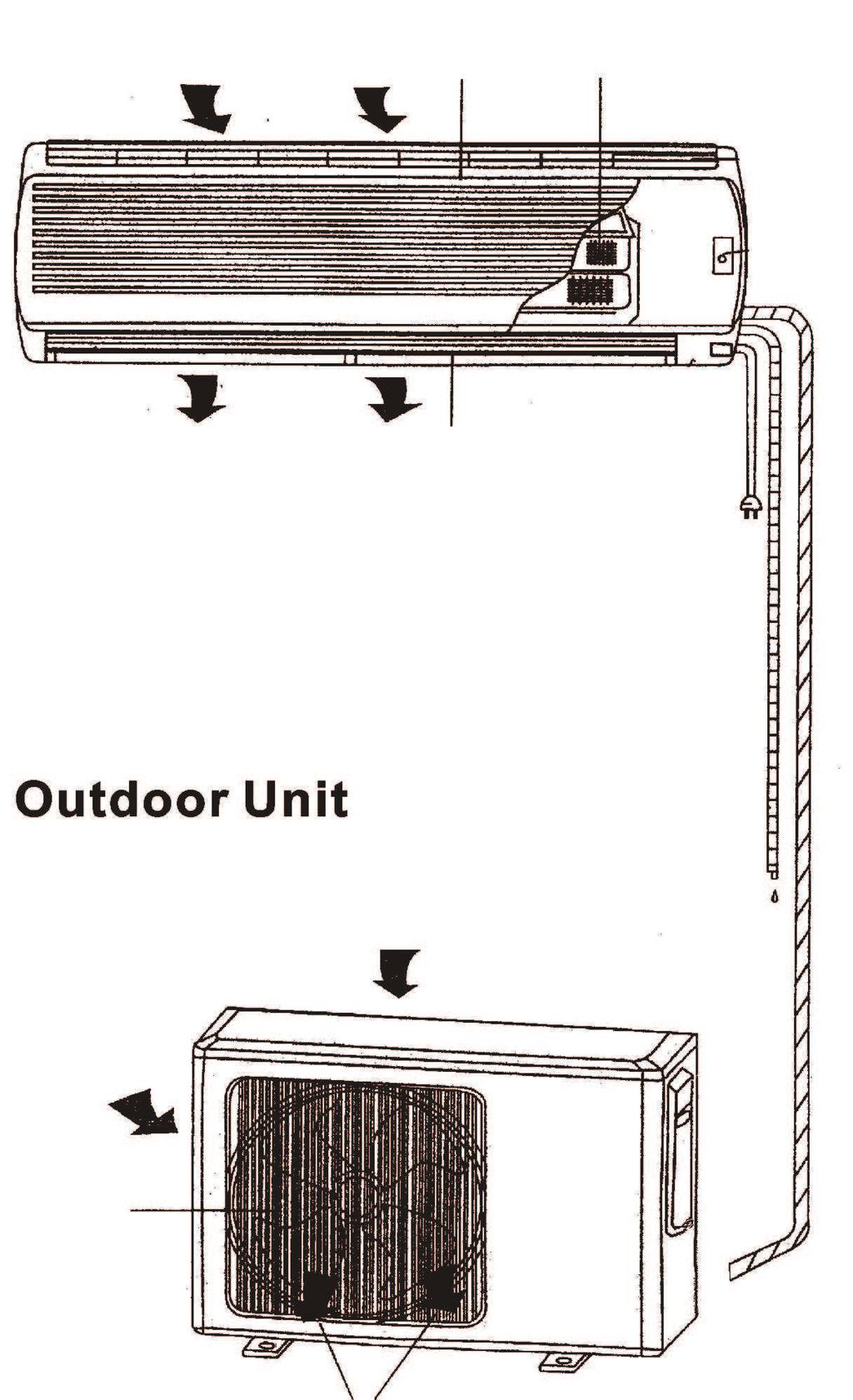
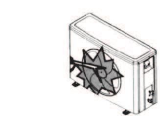
3 Chapter 1 Product Specification 1.1 Photo of Product Indoor Unit For KP Outdoor Unit Reminder: All views here are for reference only, Specifications are subject to the physical product. 1
4 1.2 Outline Indoor Unit MODEL 9000BTU 12000BTU 18000BTU 24000BTU W mm D mm 185 H mm 255 Dimensions Outdoor Unit MODEL 9000BTU 12000BTU 18000BTU 24000BTU W mm 663 D mm 254 H mm
5 Chapter 2 Refrigeration Diagrams 2.1 Cooling Only Cooling Mode Cooling Cycle Indoor heat exchanger (Evaporation) Steam-gas of low pressure Compressor (Compression) Liquid of low pressure (also a little gas) Gas of high pressure & temperature Capillary (Throttling) Super cooled liquid of high pressure 3 Outdoor heat exchanger (Condensation)
6 2.2 Cooling & Heating Cooling Mode Cooling Cycle Indoor heat exchanger (Evaporation) Steam-gas of low pressure Compressor (Compression) Liquid of low pressure (also a little gas) Capillary (Throttling) Super cooled liquid of high pressure 4-way valve (Heat pump only) Gas of high pressure & temperature Outdoor heat exchanger (Condensation) 4
7 Heating Mode Heating Cycle Indoor heat exchanger (Condensation) Gas of high Pressure & temperature Compressor (Compression) Super cooled liquid of low pressure 4-way valve (Heat pump only) Capillary (Throttling) Super cooled liquid of high pressure Steam-gas of low pressure Outdoor heat exchanger (Evaporation) 5
8 Chapter 3 Instructions of Installation SPLIT TYPE WALL MOUNTED AIR-CONDITIONER INSTALLATION INSTRUCTIONS The Installation Instructions is used to Split type wall mounted air-conditioner installation. 6
9 The distance between indoor and outdoor unit should be 5 meters and pipe length can go up to maximum 15 meters with additional refrigerant charge. Max. Allowable Tubing Length at Shipment(m) Limit of Tubing Length(m) Limit of Elevation Difference H(m) Requires Amount of Additional Refrigerant (g/m) CC 12000Btu CC 18000Btu 30
10
11
12 10
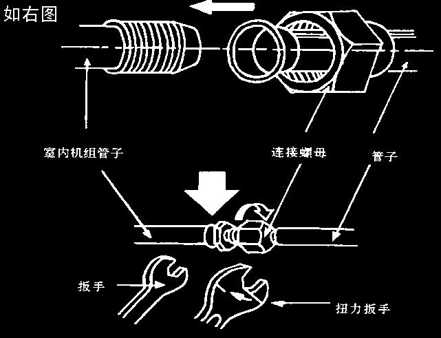
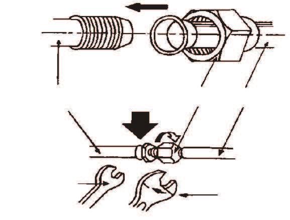
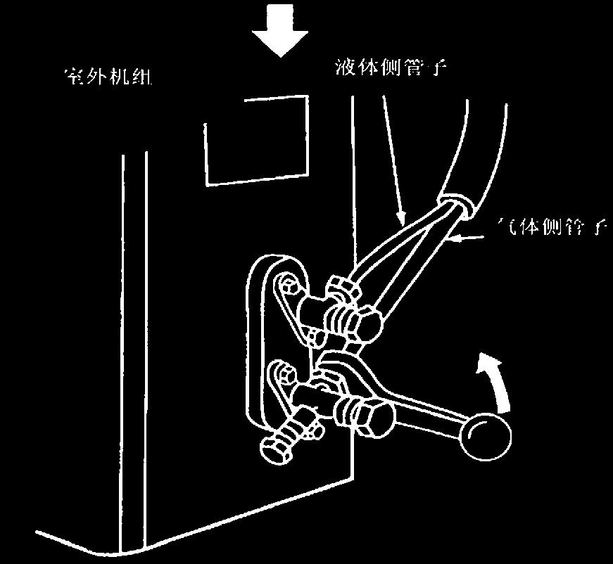
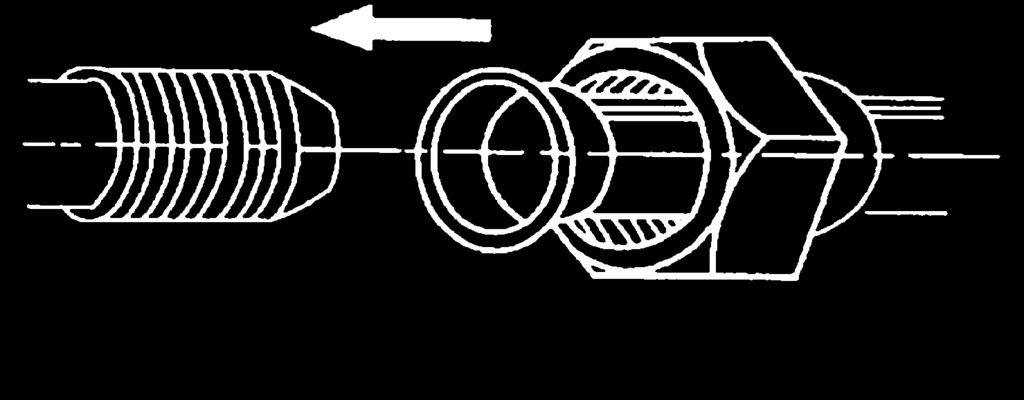
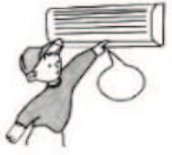
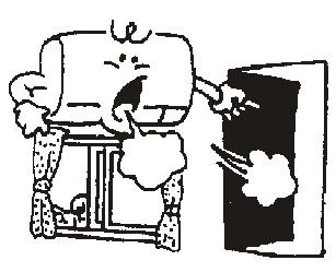
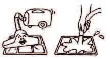
13 Technical Manual of AUX Room Air Conditioner Expelling the air: humid air in the refrigerating system might cause trouble of compressor. Take off the cover from the stop valve and T-branch valve. Take off the auxiliary cover from the T-branch valve. Turn the stop valve rod anti-clock wise to an angle of 90 degree, keep it open for 8 seconds and close the valve. Check whether there is air leakage at all connection parts of pipes. Push the top rod of T-branch valve by hexagon wrench to expel air. Repeat the third and fifth steps. Open the stop and T-branch valve with a hexagon wrench to make the unit operate. There is no leakage allowed, please check all the piping connection parts. You must test the leakage, generally, it can be tested by soap water. If the A/C is filled with R410a, make sure to discharge air and moisture remaining in the refrigerant system with a vacuum pump. (For method of using a manifold valve, refer to its operation manual.) 1.completely tighten the flare nuts, A, B, C, D, connect the manifold valve charge hose to a charge port of the low-pressure valve on the gas pipe side. 2.Connect the charge hose connection to the vacuum pump. 3.Fully open the handle Lo of the manifold valve. 4.Operate the vacuum pump to evacuate. After starting evacuation, slightly loose the flare mut of the Lo valve on the gas pipe side and check that the air is entering (Operation noise of the vacuum pump changes and a compound meter indicates 0 instead of minus.) 5.After the evacuation is complete, fully close the handle Lo of the manifold valve and stop the operation of the vacuum pump. Make evacuation for 15 minutes or more and check that compound meter 5 indicates -76cmHg(-1 10 Pa). 6.turn the stem of the packed valve B about 45 counterclockwise for 6~7 seconds after the gas coming out, then tighten the flare nut again. Make suer the pressure display in the pressure indicator is a little higher than the atmosphere pressure. 7.Remove the charge hose from the Low pressure charge hose. 8.Fully open the packed valve stems B and A. 9.Securely tighten the cap of the packed valve. Vapor side Auxiliary cover 11 Outdoor unit Outdoor unit To indoor unit Liquid side Gas side Stop valve(open) Cover T-branch valve(open) Hexagon wrench A B Packed valve Refrigerant Gas side Liquid side Compound meter -76cmHg Low pressure valve Handle Lo Charge hose Indoor unit C D Half union Manifold valve Pressure gauge Handle Hi Charge hose Vacuum pump
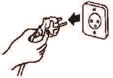
14 Technical Manual of AUX Room Air Conditioner Unscrew the screw, take off the control panel cover from the unit. Connect the cable to their terminals according to their number. The grounded wire connection: 1.loosen the grounded screw of electrical shelf. 2.Connect the grounded wire with the grounded screw then setscrew in the mark formerly. Fix the cable to the terminal board with fastening piece. Reinstall the cover with the screw. NOTE: Don't reverse the power polarity. The wrong connection lead to the mal function of some electrical parts. Must fix the screwnail of the firmly wire, then drag the wire lightly, confirmation whether it's firmly. Must changed if the wire slide, the self-drive screw can't used to the electric connection. If there is a connector, connect it directly. Terminal board for outdoor unit More than 5mm Cover Grounded wire Electrical Shelf Terminal board Heat-pump type Terminal board for outdoor unit Interconnection cord Fastener for cable connection Temperature control wire connector (only for heat pump type) Compressor signal wire connector (only for cooling pump type 6000W/7000W) Compressor signal wire connector and temperature control wire connector (only for heat pump type 6000W/7000W) Single wire and Double wires Note: Explanation for the power cord without plug (see below figure): Brown= Live wire Blue= Zero line Yellow/Green= Grounded wire 12
15 AIR-CONDITIONER REMOTE CONTROLLER INSTRUCTIONS SET TEMPERATURE( ) AUTO COOL DRY HEAT FAN HIGH MID LOW ON/OFF SET MODE CLEAN SPEED SLEEP FRESH STRONG SWING DUST FEELING HEALTH FUNGUSPROOF SCREEN TIMER Read this instructions carefully so that you can use the air-conditioner safely and correctly. Take good care of the instructions so that it can be referred to at any time. 13
16 Buttons description SET TEMPERATURE( ) LCD displays instruction TRANSMIT DIGITAL ON/OFF AUTO COOL DRY HEAT FAN HIGH MID LOW RUNNING MODE SET ROOM RUNNING MODE SPEED ON/OFF TIMER ON OFF SET MODE CLEAN SPEED SLEEP FRESH STRONG SWING DUST FEELING HEALTH FUNGUSPROOF SCREEN TIMER TIMER FEELING ON/OFF display: when the remote controller is the on state, the LCD will be displays otherwise will not be display. Digital display: Under the state of normal working. It displays set temperature, while the feeling function is start. It will displays room temperature, and under the state of timer mode. It will displays set timer. 1. ON/OFF button You can start the air-conditioner by pressing this button and stop its operation by pressing it again. 2. FRESH button This button is invalidation. 3. SPEED button You can select fan speed show as the follow: Low Med High Auto 4. STRONG button Only under the state of cooling or heating mode, press this button, the fan speed is adjusted to strong auto-maticlly and the LCD displays high fan, the strong function is started to reach the highest cooling or heating. 14
17 5. FEELING button When it displays FEELING button: Press this button can be used to set the feeling function. The LCD shows the actual room temperature when the function set and it shows the setting temperature when the function cancelled. This function is invalid when the appliance at the Fan mode. 6. DUST button This button is invalidation. 7. TIMER button Setting the ON timer time a. When remote controller is at off state, press TIMER button, the LCD displays TIMER ON and the timer time, the range of setting time is 0.5h to 24h. b. You can press the or button to adjust the timer time, each touch will be set time to increase or reduce 0.5h before 10 hours ago, after ten hours will be set time to increase or reduce 1h per pressing, to enables your required timer. c. Press TIMER button again, to set the timer on function. d. You can set another function to insure the suitable state after air conditioner turn on (including mode, temperature, swing, fan speed and etc). The LCD will displays all your setting and keep it, when the timer reach to the set time, the air conditioner will be working according to your set automatically. Setting the OFF timer time a. When remote controller is at on state, press TIMER button, the LCD displays TIMER OFF and the timer time, the range of setting time is 0.5h to 24h. b. You can press the or button to adjust the timer time, each touch will be set time to increase or reduce 0.5h before 10 hours ago, after ten hours will be set time to increase or reduce 1h per pressing, to enables your required timer. c. Press TIMER button again, to set the timer off function. 8. SCREEN button You can let the LCD displays working or not by pressing this button. 9. or button Press the + or - button,you can set the temperature range from 16 to 32,Display will change as you touch the button. 10. CLEAN button a. When remote controller is at the off state, press clean button, the wind guiding bars turn to initial postions for cooling, the A/C runs clean function with max duration 35mins.The purpose of its function is to clean dust on evapo rator and dry the inside water of evaporator and to prevent the evaporator going moldy due to water deposition and boasting strange smell. b. After setting clean function, press clean button again to cancel clean function or press ON/OFF button to cancel clean function and start A/C. c. The clean function will be no working after 35 minutes running working without any operation. 15
18 Note: clean function can be set in parallel with time start function; in this case, time start function will be executed after clean function. 11. MODE button Which enables you to select different operation mode,after each pressing, the operation mode will be changed. It shows in the following display. AUTO COOL DRY HEAT FAN AUTO Remark: cold wind type has no heating function. 12. SLEEP button 1.press the SLEEP button, the sleeping indicator light of indoor unit flashes on. 2.after the setting of sleeping mode, the cooling operation enables the set te mperature to increase 1 after 1hour and another 1 automatically after 1 hour. 3.after the setting of sleeping mode, the heating operation enables the set temperature to drop 2 after 1hour and another 2 automatically after 1 hour. 4.the air-conditioner runs in sleeping mode for 7 hours and stops automatically. Remark: press the MODE or ON/OFF button, the remote controller clears sleeping mode away. 13. SWING button Press this button, the horizontal wind direction vanes can rotate automatically, when you have the desired vertical wind direction, press it again, the horizontal wind direction vanes will be stopped at the situation of your choice. 14. HEALTH button Press this button, you can turn on or off the health function. 15. FUNGUSPROOF button This A/C has special dry and anti-mold function which has yes or no two selections. This function is controlled by the remote controller under cooling, dry and auto (cooling and dry) modes, the horizontal wind guiding bars are at the initial position for cooling. The A/C runs under heating mode(the cooling only A/C only runs under fan mode), the internal fan runs for three minutes with weak wind before stop. The purpose of this function is to dry the inside of the evaporator and to prevent the evaporator from going mouldy due to water deposition and thus disp ersing strange smell. Note: 1.This function has not been set in the factory. You may freely set and cancel this function. The setting method is: under off status of the A/C and the re mote controller, point the remote controller toward the A/C and continuously press FUNGUSPROOF pushbutton for one time, the buzzer keep beeps five times again after five times beeps, indicating that this function is ready. In case this function has been set, unless the whole A/C is powered off or the function is manually cancelled, the A/C then has this function as a default; 2.To cancel the function: 1. Power off the whole A/C; 2. Under off status of thea/c and the remote controller, point the remote controller toward the A/C and continuously press FUNGUSPROOF pushbutton for one time, the buzzer keep beeps three times again after five times beeps, indicating that this function has been cancelled; 3.When this function is on, it is suggested not to restart the A/C before it is co mpletely stop; 4.This function will not run in case of time stop or sleep stop. 16
19 Usage Fix batteries 1.Slide open the cover according the direction indicated by arrowhead. 2.Put into two brand new batteries (7#), position the batteries to right electric poles (+ -). 3.Put back the cover. Automatic operation mode 1.Press the MODE button, select the automatic operation mode. 2.Press the SPEED button, you can select fan speed.you can select fan speed from LOW, MID, HIGH, AUTO. 3.Press the ON/OFF button, the operation indicator is on, the air-conditioner starts to operate the automatic mode.press the button again, the air-conditioner stops. Cooling/Heating operation mode (cold wind type has no heating function) 1.Press the MODE button, select the Cooling or Heating operation mode. 2.Press the or button, set the temperature, temperature can be set at 1 difference range from Press the SPEED button, you can select fan speed.you can select fan speed from LOW, MID, HIGH, AUTO. 4.Press the ON/OFF button, the operation indicator is on, the air-conditioner starts to operate the automatic mode.press the button again, the air-conditioner stops. Fan operation mode 1.Press the MODE button, select the Cooling or Heating operation mode. 2.Press the SPEED button, you can select fan speed.you can select fan speed from LOW, MID, HIGH. 3.Press the ON/OFF button, the operation indicator is on, the air-conditioner starts to operate the automatic mode.press the button again, the air-conditio ner stops. Remark: In the circulation operation mode, to set the temperature is noneffective. Drying operation mode 1.Press the MODE button, select the Dry operation mode. 2.Press the or button, set the temperature, temperature can be set at 1 difference range from Press the SPEED button, you can select fan speed.you can select fan speed from LOW, MID, HIGH, AUTO. 4.Press the ON/OFF button, the operation indicator is on, the air-conditioner starts to operate the automatic mode.press the button again, the air-conditioner stops. 17
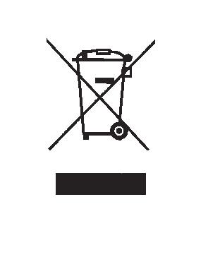
20 Night Luminous Function of Remote Controller(Only the rem ote controller with this function can be used) For your convenient use of the remote controller in the darkness without any lighting, this remote controller has blue background light and luminous pushbuttons. Function at you press on any of the pushbutton, the background light will immediately release soft light so that you are easy to operate the remote controller. If you do not operate the controller within 10 seconds, the background light will automatically disappear. Note: All the figures above are the displays after being initially electrified or re-electrified after power off. In actual operations, the remote controller screen displays related items only. Attention 1.Aim the remote controller towards the receiver on the air-conditioner. 2.The remote controller should be within 8 meters away from the receiver. 3.No obstacles between the remote controller and receiver. 4.Do not drop or throw the remote controller. 5.Do not put the remote controller under the forceful sunrays or heating facilities and other heating sources. 6.Use two 7# batteries, do not use the electric batteries. 7.Take the batteries out of remote controller before stop its using for long. 8.When the noise of transmitting signal can t be heard indoor unit or the transmission symbol on the display screen doesn t flare, batteries need be replaced. 9.If reset phenomenon occurs on pressing the button of the remote controller, the electric quantity is deficient and new batteries need to be substituted. 10.The waste battery should be disposed properly. 18
21 19
22 20


23 Chapter 5 Brief Introduction for Usage 21


24 22
25 23
26 24
27 25
28 26
29 6.1 Electric chart for 09/12/18K/12K(115V)(Non inverter) Indoor unit Chapter 6 Wiring Diagram 27
30 Outdoor unit 28
31 6.2 Electric chart for 24K(Non inverter) Indoor unit 29
32 Outdoor unit 30
33 Chapter 7 Troubleshooting Guide 7.1 Error Code No. Error Code Problem 1 E1 Temperature sensor of air intake fault 2 E2 Temperature sensor of outdoor coil fault 3 E3 Temperature sensor of indoor coil fault 4 E4 PG motor of indoor unit feedback fault 7.2 Troubleshooting Guide for 09-12K 1. The Foremost Inspecting Items The input voltage must be within +10% tolerance of the rated Voltage. If it is not the case, the air-conditioner will probably not work normally. Check the connecting cord between indoor unit and outdoor unit to see if it is properly connected. The connecting must be done according to the wiring diagram, please also notice that even different models may have the connecting cord of the same specification. Please check if the marks at the connecting terminal and the marks on the cord can match, otherwise, the air-conditioner will not work normally. If the following phenomena are found, the problem is not from the air-conditioner itself. 31
34 NO. Problems Causes The motor is heard operating but the air-conditioner dose not work when the indoor unit is powered on The compressor stops running but the indoor fan motor keeps working when it is at cooling mode with the indoor temperature higher than set temperature. The compressor works discontinuously at dehumidifying mode. The air-conditioner does not work while the LED display is on. The compressor works discontinuously at cooling and dehumidifying mode, and the indoor fan motor slows down. Since the air-conditioner is powered on, it will come to working condition as long as you press the ON/OFF button of the remote control and the Signal is well received. If you turn off the air-conditioner and restart it immediately, it will return to normal in 3 minutes, after that, the air-conditioner will automatically adjust the indoor fan speed to what you set. The air-conditioner will automatically control the working of the compressor according to the inside temperature The TIMER is set with the air-conditioner; it will be in hold on condition. If the TIMER setting is cancelled, the air-conditioner will return to normal working condition The compressor stops internally or the fan motor slows down to prevent the indoor heat exchanger from being frozen. 32
35 2. No Power Display Items a) Check if the input voltage is correct? b) Check if the AC power supply connecting is correct? c) Check if the output voltage of the manostat L7805 (IC2) is correct? Trouble shooting procedure 33
36 3. The Indoor Fan Motor Does Not Work Items a) Check if the indoor fan motor is connected correctly to the connector (CN8)? b) Check if the AC input voltage is correct? c) Check if the IC of indoor fan motor is connected correctly to the connector (CN2)? d) Check if the capacity of indoor fan motor is connected correctly to the connector (CN8)? Trouble shooting procedure 34
37 4. The Outdoor Unit Does Not Work Items a) Check if the input voltage is correct? b) Check if the wire connection of the outdoor connecting terminal is correct? Trouble shooting procedure 35
38 5. The Step Motor Does Not Work Items a) Check if the input voltage is correct? b) Check if the step motor controlling the up-down movement firmly connected to Cn2? Trouble shooting procedure 36
39 6. Heating Mode Can Work, But No Hot Air Blow Check if the set temperature is lower than the indoor temperature? Check if the indoor PCB is connected to the terminal correctly? 37
40 7. Remote Control Can Not Work Trouble shooting procedure 38
41 8. The Failure Analysis of the Main Parts 39
42 7.3 Troubleshooting Guide for 18-36K 1. The Foremost Inspecting Items The input voltage must be within +10% tolerance of the rated Voltage. If it is not the case, the air-conditioner will probably not work normally. Check the connecting cord between indoor unit and outdoor unit to see if it is properly connected. The connecting must be done according to the wiring diagram, please also notice that even different models may have the connecting cord of the same specification. Please check if the marks at the connecting terminal and the marks on the cord can match, otherwise, the air-conditioner will not work normally. If the following phenomena are found, the problem is not from the air-conditioner itself. NO. Problems Causes The motor is heard operating but the air-conditioner dose not work when the indoor unit is powered on The compressor stops running but the indoor fan motor keeps working when it is at cooling mode with the indoor temperature higher than set temperature. The compressor works discontinuously at dehumidifying mode. The air-conditioner does not work while the LED display is on. The compressor works discontinuously at cooling and dehumidifying mode, and the indoor fan motor slows down. Since the air-conditioner is powered on, it will come to working condition as long as you press the ON/OFF button of the remote control and the signal is well received. If you turn off the air-conditioner and restart it immediately, it will return to normal in 3 minutes, after that, the air-conditioner will automatically adjust the indoor fan speed to what you set. The air-conditioner will automatically control the working of the compressor according to the inside temperature The TIMER is set with the air-conditioner; it will be in hold on condition. If the TIMER setting is cancelled, the air-conditioner will return to normal working condition. The compressor stops internally or the fan motor slows down to prevent the indoor heat exchanger from being frozen. 40
43 2. No Power Display Items Check if the input voltage is correct? Check if the AC power supply connecting is correct? Check if the output voltage of the manostat L7805(IC2)is correct? Trouble shooting procedure 41
44 3. The Indoor Fan Motor Does Not Work Items Check if the indoor fan motor is connected correctly to the connector(cn8)? Check if the AC input voltage is correct? Check if the IC of indoor fan motor is connected correctly to the connector(cn2)? Check if the capacity of indoor fan motor is connected correctly to the connector(cn8)? Trouble shooting procedure 42
45 4. The Outdoor Unit Does Not Work Items Check if the input voltage is correct? Check if the wire connection of the outdoor connecting terminal is correct? Trouble shooting procedure 43
46 5. The Step Motor Does Not Work Items Check if the input voltage is correct? Check if the step motor controlling the up-down movement firmly connected to Cn2? Trouble shooting procedure 44
47 6. Heating Mode Can Work, But No Hot Air Blow Check if the set temperature is lower than the indoor temperature? Check if the indoor PCB is connected to the terminal correctly? 45
48 7. Remote Control Can Not Work Trouble shooting procedure 46
49 8. The Failure Analysis of the Main Parts 47
50 8.1 Ind oo r unit fo r P A C /P P Technical Manual of AUX Air Conditioner Chapter 8 Exploded Views & Parts List C A
51 Parts List of Indoor unit for PAC9041 Exploded View No Chinese Name Name Pcs Remark 1 Panel 1 2 Display board 1 3 Indication lamp holder 1 4 Electrostatic precipitator 1 5 Sterilization filter 1 6 Filter 2 7 In box screw cap 3 8 Horizontal air-blade 1 9 Cover of medium frame 1 10 Panel clasper 1 11 Stand bar 2 12 Medium frame 1 13 Wire mesh enclosure 1 14 sleeve 1 15 Step motor 1 16 Air-vent holder 1 17 Vertical air-blade 2 18 Bracket of airflow vanes 1 19 Evaporator assembly 1 20 Cross flow fan 1 21 Fan motor 1 22 Motor cover 1 23 Negative ion 1 24 Chassis 1 25 Mounting plate 1 26 Left plastic-crutch for evaporator 1 27 Bearing holder for indoor fan 1 28 Cover of controller box 1 29 Power supply clamp 1 30 Connection cable clamp 1 31 Terminal board 1 32 Main PCB 1 33 Controller box 1 34 Transformer 1 35 Power supply 1 36 Connection cable 1 49
52 8.2.1 Outdoor un it fo r PAC9041 Technical Manual of AUX Air Conditioner 50
53 Exploded View No Parts List of Outdoor unit for PAC9041 Chinese Name Name Pcs Remarks Electric cover Right side plate Gas valve assembly Liquid valve assembly Valve plate Chassis assembly right footing Pump bolt left footing rubber cushion Compressor assembly Big washer Hexagonal nut Front net Panel Hexagonal nut Light spring washer Propeller fan Fan motor Holder for fan motor Partition plate Left clapboard Top cover board 1 Condensor assembly 1 Front net 1 Condenser inlet pipe 1 assembly 4-Ways valve pipe assembly 1 optional (for HP) Capillary assembly 1 Fan motor capacitor Capacitor clamp 1 Compressor capacitor Holder for E-parts Terminal board electricity cord clamp 51
54 8.2.2 Outdoor un it fo r PAC12041 Technical Manual of AUX Air Conditioner 52
55 Exploded View No Parts List of Outdoor unit for PAC12041 Chinese Name Name Pcs Remark Panel net 1 Panel 1 Axial-flow fan 1 Fan motor 1 Motor bracket 1 Condenser assembly 1 Top cover 1 Partition plate 1 Compressor capacitor 1 Capacitor clamp 1 Fan motor capacitor 1 Holder of electrical unit 1 Terminal board 1 Chassis assembly 1 Handle 1 Back net 1 Right side plate 1 Liquid valve 1 Gas valve 1 Valve plate 1 Compressor tubing assembly 1 Air inlet tube of condenser 1 Compressor 1 Capillary 1 Left side plate 1 53
56 8.3 Ind oo r unit fo r P A C Technical Manual of AUX Air Conditioner 54
57 Parts List of Indoor unit for PAC18041 No Name Quantity Remark 1 Panel 1 2 Filter 2 3 Panel clasper 3 4 Medium frame 1 5 Horizontal airflow blade 1 6 Air-vent holder 2 7 Connecting rod for airflow vanes 1 8 A Vertical airflow vanes A 7 9 B Vertical airflow vanes B 7 10 Bracket of airflow vanes 1 11 Bearing for indoor fan 1 12 Cross-flow fan 1 13 Left-hand propping holder for evaporator 1 14 Evaporator assembly 1 15 chassis 1 16 Foam of left chassis 1 17 Mounting plate 1 18 Foam of right chassis 1 19 Pipe clamp 1 20 Negative ion 1 21 Right-hand propping holder for evaporator 1 22 Motor cover 1 23 Indoor fan motor 1 24 Step motor of airflow vanes 1 25 Controller box 1 26 Vertical airflow vanes 1 27 Transformer 1 28 A Clamp of cable A 1 29 B Clamp of cable B 1 30 Room temperature sensor 1 31 PCB Main PCB 1 32 Step motor of airflow blade 1 33 pipe temperature sensor 1 34 Terminal board 1 35 Cover of controller box 1 36 Connection cable 1 37 Power supply plug 1 38 Screw cover 1 39 Cover of medium frame 1 40 Stand bar Display light board assemblly 1 43 Panel 1
58 Outdoo r unit fo r PAC18041 Technical Manual of AUX Air Conditioner 56
59 Parts List of Outdoor unit for PAC18041 NO component Item Description Pcs Remark 57
60 8.4 Ind oo r unit fo r P A C Technical Manual of AUX Air Conditioner 58
61 Parts List of Indoor unit for PAC24041 No Name Quantity Remark 1 Panel 1 2 Filter 2 3 Panel clasper 3 4 Medium frame 1 5 Horizontal airflow blade 1 6 Air-vent holder 2 7 Connecting rod for airflow vanes 1 8 A Vertical airflow vanes A 7 9 B Vertical airflow vanes B 7 10 Bracket of airflow vanes 1 11 Bearing for indoor fan 1 12 Cross-flow fan 1 13 Left-hand propping holder for evaporator 1 14 Evaporator assembly 1 15 chassis 1 16 Foam of left chassis 1 17 Mounting plate 1 18 Foam of right chassis 1 19 Pipe clamp 1 20 Negative ion 1 optional 21 Right-hand propping holder for evaporator 1 22 Motor cover 1 23 Indoor fan motor 1 24 Step motor of airflow vanes 1 25 Controller box 1 26 Vertical airflow vanes 1 27 Transformer 1 28 A Clamp of cable A 1 29 B Clamp of cable B 1 30 Room temperature sensor 1 31 PCB Main PCB 1 32 Step motor of airflow blade 1 33 pipe temperature sensor 1 34 Terminal board 1 35 Cover of controller box 1 36 Connection cable 1 37 Power supply plug 1 38 Screw cover 1 39 Cover of medium frame 1 40 Stand bar 1 41 Holder of display board 1 42 Display screen 1 43 Panel 1 59
62 Outdoor unit for PAC Technical Manual of AUX Air Conditioner
63 Parts List of Outdoor unit for PAC24041 Exploded View No Chinese Name Name Pcs Remark Left clapboard Front net Big flat head self-drilling screw Top cover board Panel Condensor assembly Right side plate Capacitor clamp Compressor capacitor Fan motor capacitor Electric cover Holder for E-parts Terminal board Partition plate Compressor assembly Capillary assembly Compressor pipe assenbly Liquid valve assembly Gas valve assembly Chassis assembly Phillips screw Valve plate Propeller fan Holder for fan motor Fan motor Phillips pan head self-drilling screw 61

64
AUTO COOL DRY HEAT FAN SPEED TURBO HIGH MID LOW AUTO. SLEEP iclean HEALTH ifavor Eheater Anti-FUNGUS DISPLAY LOCK. TURBO TIMER ifavor
 AIR-CONDITIONER REMOTE CONTROLLER INSTRUCTIONS AUTO COOL DRY HEAT FAN SPEED TURBO HIGH MID LOW AUTO TIMER C SET F ONOFF h ROOM SWING ON OFF SWING SLEEP iclean HEALTH ifavor Eheater Anti-FUNGUS DISPLAY
AIR-CONDITIONER REMOTE CONTROLLER INSTRUCTIONS
 AIR-CONDITIONER REMOTE CONTROLLER INSTRUCTIONS SET TEMPERATURE( ) AUTO 自动 COOL DRY HEAT FAN SPEED 制冷 TURBO HIGH MID LOW AUTO 制热 HOUR ON OFF SET ROOM C ON HEALTH LOCK SLEEP DISPLAY Anti-FUNGUS SET ON/OFF
CONTENTS. Product Specification..1 Refrigeration Diagram.. 3 Wiring Diagram.6 Troubleshooting Guide...9
 E E e i e M nu l I OO I O I IO or it ount d ri In rt r od or I I I O I I I O I I I O I I I O le se Please read e this t is owner o ne s manual s m nu l carefully e ull and n t o ou l thoroughly before
KSIA SERIES SPLIT TYPE ROOM AIR CONDITIONER. For Split Wall Mounted Series R410a Inverter Model Type For F
 KSIA SERIES ro le oo SPLIT TYPE ROOM AIR CONDITIONER For Split Wall Mounted Series R410a Inverter Model Type For F KSIA009-H216-I / KSIA009-H216-O KSIA012-H216-I / KSIA012-H216-O KSIA018-H216-I / KSIA018-H216-O
TAC-09CHSA/*** TAC-12CHSA/*** TAC-18CHSA/*** TAC-24CHSA/*** SERVICE MANUAL WALL MOUNTED SPLIT-TYPEAIR CONDITIONERS. No.TE1307.
 WALL SPLIT-TYP WALL MOUNTED SPLIT-TYPEAIR CONDITIONERS MOUNTED SERVICE MANUAL No.TE1307 Models: TAC-09CHSA/*** TAC-12CHSA/*** TAC-18CHSA/*** TAC-24CHSA/*** CONTENTS: 1. IMPORTANT NOTICE 2. OPERATION DETAILS
TAC-09CS/K TAC-12CS/K TAC-18CS/K TAC-24CS/K TAC-07CHS/K TAC-09CHS/K TAC-12CHS/K TAC-18CHS/K TAC-24CHS/K
 TCL WALL MOUNTED SPLIT-TYPE AIR CONDITIONERS SERVICE MANUAL No.TE040427 Models TAC-07CS/K TAC-09CS/K TAC-2CS/K TAC-8CS/K TAC-24CS/K TAC-07CHS/K TAC-09CHS/K TAC-2CHS/K TAC-8CHS/K TAC-24CHS/K CONTENTS. IMPORTANT
TCL SERVICE MANUAL. Models WALL MOUNTED SPLIT-TYPE AIR CONDITIONERS. No.TE CONTENTS
 TCL WALL MOUNTED SPLIT-TYPE AIR CONDITIONERS SERVICE MANUAL No.TE031229 Models TAC-07CS/K TAC-09CS/K TAC-12CS/K TAC-18CS/K TAC-24CS/K TAC-07CSC/K TAC-09CSC/K TAC-12CSC/K TAC-18CSC/K TAC-24CSC/K TAC-07CHS/K
SPLIT TYPE AC AND MULTI SPLIT AC SERVICE MANUAL
 SPLIT TYPE AC AND MULTI SPLIT AC SERVICE MANUAL Model:PAC9039/GPAC9039/PAC12519/PMA1212/PAC12039/ PAC13039/PAD12060EN/PAD12080A/GPAC12039/PAC18039/ PAD18060EN/GPAC18039/PAC24039/PAD24060EN/GPAC24039/ PAC30039/PAC36039
Service Manual. Room Air Conditioner Split Wall-Mounted Type. Applies to: HSG-09HRN1 HSG-12HRN1 HSG-18HRN1 HSG-24HRN1
 Service Manual Room Air Conditioner Split Wall-Mounted Type Applies to: HSG-09CRN1 HSG-12CRN1 HSG-18CRN1 HSG-24CRN1 HSG-09HRN1 HSG-12HRN1 HSG-18HRN1 HSG-24HRN1 NOTE: Please read this first before servicing
Service Manual. Contents. 1.Important Notice Technical Specification Operation Details Wiring Diagram...
 Split type Wall Mounted Air Conditioner E series Service Manual Contents 1.Important Notice...1 2.Technical Specification...2-9 3.Operation Details...10-13 4.Wiring Diagram...14-15 5.Troubleshooting Guide...16-23
YC ON-OFF SERIES. Service Manual
 YC ON-OFF SERIES Service Manual CONTENTS 1. Precaution... 3 1.1 Safety Precaution... 3 1.2 Warning... 3 2. Model Lists... 6 3. Dimension... 7 3.1 Indoor Unit... 7 3.2 Outdoor Unit... 11 4. Refrigerant
Owner s Manual. Split type wall mounted air-conditioner. Please read this owner s manual carefully and thoroughly before operating the unit!
 , Owner s Manual Split type wall mounted air-conditioner Please read this owner s manual carefully and thoroughly before operating the unit! Take care of this manual for future reference., CONTENTS Safety
INVERTER SPLIT - TYPE
 INVERTER SPLIT - TYPE ISSUE No 2 DATE 04/09/08 P/No 2020323A2868 CONTENTS SAFETY PRECAUTIONS Warning 2 Operating temperature 2 BEFORE INSTALLATION Tools needed for installation 3 Items required for installing
TREO SERVICE MANUAL. Models WALL MOUNTED SPLIT-TYPE AIR CONDITIONERS. No.TE CONTENTS
 TREO WALL MOUNTED SPLIT-TYPE AIR CONDITIONERS SERVICE MANUAL No.TE121112 Models CS-H09UT1 CS-H18UT1 CS-H12UT1 CS-H24UT1 CONTENTS 1. IMPORTANT NOTICE 2 2. OPERATION DETAILS 3 3. WIRING DIAGRAM 11 4. EXPLOSION
SERVICE MANUAL ROOM AIR CONDITIONER TAN/TAG-A28FWIS TAN/TAG-A32FWIS CONTENTS
 SERVICE MANUAL ROOM AIR CONDITIONER TAN/TAG-A28FWIS TAN/TAG-A32FWIS CONTENTS SPECIFICATION... 1 FUNCTIONS... 5 SERVICE FUNCTION EXPLANATION... 7 OPERATION DETAILS... 8 TROUBLESHOOTING GUIDE... 13 PERFORMANCE
Service Manual & Installation Manual
 GE Consumer & Industrial Appliances Service Manual & Installation Manual Split System Air Conditioner Model numbers: GE AIR F24 GE AIR F34 GE AIR F41 1 2 3 Introduction and Features Model Remarks GE AIR
WALL MOUNTED type SPLIT TYPE ROOM AIR CONDITIONER CONTENTS. Models
 SPLIT TYPE ROOM AIR CONDITIONER WALL MOUNTED type Models Indoor unit ASY9USCCW ASY9USCCW ASY12USCCW Outdoor unit AOY9USCC AOY9UFCC AOY12USCC CONTENTS SPECIFICATIONS................................... 1
SERVICE Manual FREE JOINT MULTI AIR CONDITIONER
 FREE JOINT MULTI AIR CONDITIONER INDOOR UNIT MH020FPEA MH023FPEA MH026FPEA MH035FPEA MH052FPEA MH8VP2-09 MH9VP2-07 MH9VP2-2 MH026FKEA MH035FKEA MH052FDEA OUTDOOR UNIT MH8VP2X MH9VP2X MH052FXEA2 MH068FXEA4
PC20-AMFII / PC40-AMF USER MANUAL
 VERY IMPORTANT PC20-AMFII / PC40-AMF USER MANUAL Please read this instruction guide before install and using your portable air conditioner unit. This instruction manual is the universal-purpose version
Free Stand Air Conditioner. Model: 42/38KFJ /38KFJ /38QFJ /38QFJ048833
 Free Stand Air Conditioner Model: 42/38KFJ024733 42/38KFJ048833 42/38QFJ024733 42/38QFJ048833 Content CONTENT 1 Safety Precautions...1 1.1 Precaution... 1 1.2 Installation... 1 1.3 Caution... 1 1.4 Operational...
BEFORE USING THE APPLIANCE SAFETY PRECAUTIONS AIR CONDITIONER PRECAUTIONS
 BEFORE USING THE APPLIANCE To make the most out of your new appliance, please read the user instructions carefully and keep them handy for future consultation. SAFETY PRECAUTIONS The Installation and service/repair
0RGHOV,QGRRU 8QLW MWM36Y3J 2XWGRRU 8QLW MRM36Y3J 11
 MWM36Y3J MRM36Y3J 11 Content Operation Notices Precautions...1 Parts name...2 Screen Operation Guide Buttons on remote controller...3 Introduction for icons on display screen...3 Introduction for buttons
Room Air Conditioner Service and Parts Manual
 Cool Dry Mode Temp Room Air Conditioner Service and Parts Manual 0F Fan Speed hr Timer 0n/0ff Money Saver Fan Only Auto Swing Power CP10 CP12 CP10 - CP12 (06/14) 93011402_04 CONTENTS 1. PREFACE 1.1 SAFETY
Westinghouse. Split System Inverter Series. Service Manual
 Westinghouse Split System Inverter Series Service Manual Model: WIWPK/WCHPK Range: 2.6kw 7.6kw CONTENTS 1. Precaution... 1 1.1 Safety Precaution... 1 1.2 Warning... 1 2. Function... 5 3. Dimension... 6
XIDEKO AIR CONDITIONERS
 XIDEKO AIR CONDITIONERS Version No. 1904871-03 Split Type Room Air Conditioner Use and Care Manual Preparation before use Safety Precautions Identification of parts Indoor unit Outdoor unit Operating and
High Wall SERVICE MANUAL. TLCA-TLHA 07 to 18 FSAAAR TLCA-07 / TLHA-07 TLCA-09 / TLHA-09 TLCA-12 / TLHA-12 TLCA-18 / TLHA-18 SM-TLCA-TLHA-07-18GB 06-08
 High Wall TLCA-TLHA 07 to 18 FSAAAR SERVICE MANUAL TLCA-07 / TLHA-07 TLCA-09 / TLHA-09 TLCA-12 / TLHA-12 TLCA-18 / TLHA-18 SM-TLCA-TLHA-07-18GB 06-08 1. Precaution 1.1 Safety Precaution To prevent injury
Room Air Conditioner CP06 & CP08. Chill 115 Volts. Service & Parts Manual THE EXPERTS IN ROOM AIR CONDITIONING _02
 Room Air Conditioner Service & Parts Manual 2014-2015 CP06 & CP08 Chill 115 Volts THE EXPERTS IN ROOM AIR CONDITIONING 93011401_02 CONTENTS 1. PREFACE 1.1 SAFETY PRECAUTIONS...2 1.2 INSULATION RESISTANCE
Portable Room Air Conditioner and Heat Pump
 Installation, Operation & Maintenance Manual Portable Room Air Conditioner and Heat Pump PS-121B PSH-141A Thank you for purchasing our Portable Air Conditioner. French version of this manual is available
F SERIES ON-OFF SERIES. Service Manual 2016
 F SERIES ON-OFF SERIES Service Manual 2016 CONTENTS 1. Precaution... 3 1.1 Safety Precaution... 3 1.2 Warning... 3 2. Function... 6 3. Dimension... 7 3.1 Indoor Unit... 7 3.2 Outdoor Unit... 9 4. Refrigerant
USER MANUAL AND INSTALLATION MANUAL
 SPLIT TYPE WALL MOUNTED ON/OFF AIR CONDITIONER USER MANUAL AND INSTALLATION MANUAL MODELS: SC009 SC012 SC018 SC022 BEFORE USING THE APPLIANCE To make the most out of your new appliance, please read the
Reverse Cycle Inverter Split System Air Conditioner
 PROTECT YOUR WARRANTY This unit must be installed by a registered, licensed installer as required by Government regulations. Reverse Cycle Inverter Split System Air Conditioner Model Number STR-SSAC12000
USER'S & INSTALLATION MANUAL
 Before using your air conditioner, please read this manual carefully and keep it for future reference. SPLIT TYPE ROOM AIR CONDITIONER USER'S & INSTALLATION MANUAL SERIES Read This Manual Keep this manual
Content Precaution...2 Function...3 Dimension...5 Refrigerant cycle diagram...7 Operation limits...8 Wiring diagram...9 Installation details...
 Cover Content Content 1. Precaution...2 1.1 Safety Precaution...2 1.2 Warning...2 2. Function...3 3. Dimension...5 3.1 Indoor unit...5 3.2 Outdoor unit...5 4. Refrigerant cycle diagram...7 5. Operation
INSTALLATION MANUAL. Split-type Air Conditioner (Cooling and Heating) Outdoor Unit UQB09JJWC UQB12JJWC. Indoor Unit AQB09JJWC AQB12JJWC
 Outdoor Unit UQB09JJWC UQB12JJWC. Indoor Unit AQB09JJWC AQB12JJWC") AQB09JJ6WC_IM_E_2585 2006.4.17 4:26 PM Page 17 INSTALLATION MANUAL Indoor Unit AQB09JJWC AQB12JJWC Outdoor Unit UQB09JJWC UQB12JJWC ENGLISH FRANÇAIS ESPAÑOL Split-type Air Conditioner (Cooling and Heating)
AQB09JJ6WC_IM_E_2585 2006.4.17 4:26 PM Page 17 INSTALLATION MANUAL Indoor Unit AQB09JJWC AQB12JJWC Outdoor Unit UQB09JJWC UQB12JJWC ENGLISH FRANÇAIS ESPAÑOL Split-type Air Conditioner (Cooling and Heating)
Room Air Conditioner Service and Parts Manual
 Cool Dry Temp Mode Room Air Conditioner Service and Parts Manual F Fan Speed hr Timer 0n 0ff Money Saver Fan Only Auto Swing Power CP06 CP08 93011401_01 CONTENTS 1. PREFACE 1.1 SAFETY PRECAUTIONS...2 1.2
TABLE OF CONTENTS. NOTE: Read the entire instruction manual before starting the installation. TROUBLESHOOTING... 13
 R 410A Duct Free Split System Air Conditioner and Heat Pump Product Family: DFS4(A/H) System, DFC4(A/H)3 Outdoor, DFF4(A/H)H Indoor NOTE: Read the entire instruction manual before starting the installation.
FAN COIL USER MANUAL TC18C2DWB1 TC24C2DWB1 TC37C2DWB1 TC48C2DWB1 TC60C2DWB Innovair Corporation. All Rights Reserved.
 FAN COIL USER MANUAL TC18C2DWB1 TC24C2DWB1 TC37C2DWB1 TC48C2DWB1 TC60C2DWB1 Duct Type 1. Features...7 2. Dimensions...8 3. Service Space...9 4. Wiring Diagrams...10 5. Capacity Tables...11 6. Capacity
Portable Air Conditioner Instruction Manual
 Portable Air Conditioner Instruction Manual WA-1240AE1: 12,000BTU (cooling only) WA-1240H1: 12,000BTU (cooling & heating) WA-1420E1: 14,000BTU (cooling only) WA-1420H1: 14,000BTU (cooling & heating) Thank
DAEWOO SERVICE MANUAL DSC-1245FL DSC-1285FL DSC-1285FLH. Models WALL MOUNTED SPLIT-TYPE AIR CONDITIONERS. No CONTENTS
 DAEWOO WALL MOUNTED SPLIT-TYPE AIR CONDITIONERS SERVICE MANUAL No.20160824 Models DSC-1245FL DSC-1285FL DSC-1285FLH CONTENTS 1. IMPORTANT NOTICE 2. PRODUCT DIMENSIONS 3. REFRIGERATION CYCLE DIAGRAM 4.
Service Manual. Air Conditional
 Air Conditional Service Manual Большая библиотека технической документации http://splitoff.ru/tehn-doc.html каталоги, инструкции, сервисные мануалы, схемы. -2 - MODEL: AC-FR30CM -3 - CONTENTS SPECIFICATION...
PAC12J. 12,000btu Cool & Heat Portable Air Conditioner. Please read this manual carefully prior to operating the product.
 USER MANUAL Portable Air Conditioner and Heater With Heat Pump Technology PAC12J 12,000btu Cool & Heat Portable Air Conditioner Please read this manual carefully prior to operating the product. Please
USER MANUAL TPS-M5/M55/M555
 VERY IMPORTANT Please read this instruction guide before install and using your mini portable type air conditioner unit. This instruction manual is the universal-purpose version for the units that you
SERVICE MANUAL SPLIT WALL-MOUNTED TYPE MODELS MWCOHC30S/MRCOHC30AS MWCOHC36S/MRCOHC36AS
 SERVICE MANUAL SPLIT WALL-MOUNTED TYPE MODELS MWCOHC30S/MRCOHC30AS MWCOHC36S/MRCOHC36AS CONTENTS 1. Precaution... 1 1.1 Safety Precaution... 1 1.2 Warning... 1 2. Function... 6 3. Dimension... 7 3.1 Indoor
Dual-Hose Portable Air Conditioner User Manual
 Dual-Hose Portable Air Conditioner User Manual Model: IPA2-1244-C Read This Manual Inside you will find many helpful hints on how to use and maintain your air conditioner properly. Just a little preventive
SERVICE MANUAL PORTABLE AIR CONDITIONER PAC-10000DB NEW WIDETECH V 50Hz
 IDETECH R NE IDETECH SERVICE MANUAL PORTABLE AIR CONDITIONER PAC-0000DB Important points on service, and flow chart for inspecting and repairing the unit... Appearance(out ward)... Troubleshooting... 3
Installation Instructions
 8GXM / 0GXM Multi---Split High---Wall Duct Free Split System 8GXM --- Size 18k, k, and 0k 0GXM --- Size 9k, 1k, and 18k Installation Instructions NOTE: Read the entire instruction manual before starting
OWNER'S MANUAL R-410A Duct Free Split System Air Conditioner and Heat Pump
 R-10A Duct Free Split System Air Conditioner and Heat Pump Product Family: DFF(A/H)H, DFC(A/H) Please read the operating instructions and safety precautions carefully and thoroughly before installing and
INSTALLATION MANUAL. Split-type Air Conditioner (Cooling and Heating) Indoor Unit AQB18J6WC AQB24J2WC. Outdoor Unit UQB18J6WC UQB24J2WC
 Indoor Unit AQB18J6WC AQB24J2WC. Outdoor Unit UQB18J6WC UQB24J2WC") AQB8J6WC_IM_E_25864 2006.4.4 3:29 PM Page 7 INSTALLATION MANUAL Indoor Unit AQB8J6WC AQB24J2WC Outdoor Unit UQB8J6WC UQB24J2WC ENGLISH FRANÇAIS ESPAÑOL Split-type Air Conditioner (Cooling and Heating)
AQB8J6WC_IM_E_25864 2006.4.4 3:29 PM Page 7 INSTALLATION MANUAL Indoor Unit AQB8J6WC AQB24J2WC Outdoor Unit UQB8J6WC UQB24J2WC ENGLISH FRANÇAIS ESPAÑOL Split-type Air Conditioner (Cooling and Heating)
Installation Instructions
 40MAQ / 38MAQ 619PB / 538PR High---Wall Ductless Split System Sizes 09 to 30 Installation Instructions TABLE OF CONTENTS PAGE PARTS LIST... 2 SAFETY CONSIDERATIONS... 3 SYSTEM REQUIREMENTS... 4 DIMENSIONS...
Service Manual A16EW4H4R09 A16EW4H4R12 A16EW4H4R18
 Service Manual A16EW4H4R09 A16EW4H4R12 A16EW4H4R18 ON/ OFF MODE FAN CLOCK TIMER ON X-FAN TEMP TIMER OFF TURBO SLEEP LIGHT A16EW4H4R09 A16EW4H4R12 A16EW4H4R18 1 2 A16EW4H4R09 A16EW4H4R12 A16EW4H4R18 3
INSTALLATION MANUAL SPLIT TYPE ROOM AIR CONDITIONER (PART NO )
") SPLIT TYPE ROOM AIR CONDITIONER INSTALLATION MANUAL (PART NO. 9312791019-01) This air conditioner uses new refrigerant HFC (R410A). The basic installation work procedures are the same as conventional refrigerant
SPLIT TYPE ROOM AIR CONDITIONER INSTALLATION MANUAL (PART NO. 9312791019-01) This air conditioner uses new refrigerant HFC (R410A). The basic installation work procedures are the same as conventional refrigerant
II PCV1 Features
 II-15-24-43-PCV1 FLOOR STANDING CABINET TYPE HEAT PUMP COOLING CAPACITY: 4,6 kw - 12,6 Kw HEATING CAPACITY: 4,7 kw - 13,0 kw R410A Scroll The new Interklima floor standing CABINET type heat pumps are the
Chiltrix 5.1 Thin DC - Inverter Water Fan Coil Unit Floor, Wall or Ceiling Universal Mount Manual
 Chiltrix 5.1 Thin DC - Inverter Water Fan Coil Unit Floor, Wall or Ceiling Universal Mount Manual Version 1.5 1 CONTENTS CHAPTER 1 GENERAL INTRODUCTION...3 1. Preface... 3 2. Product Introduction... 3
OWNER S MANUAL. R 410A Ductless Split System Air Conditioner and Heat Pump
 R 410A Ductless Split System Air Conditioner and Heat Pump Models DLC4(A/H) Outdoor Unit, DLF4(A/H) Indoor Unit Sizes 9K, 12K, 18K, 24K, 30K and 36K Please read the operating instructions and safety precautions
AOYG18LFC OUTDOOR UNIT INSTALLATION MANUAL INSTALLATION MANUAL. For authorized service personnel only. PART NO
 AOYG8LFC OUTDOOR UNIT INSTALLATION MANUAL INSTALLATION MANUAL For authorized service personnel only. English PART NO. 93778639 93778639_IM.indb /20/20 6:07:25 PM AIR CONDITIONER OUTDOOR UNIT INSTALLATION
Room Air Conditioner CONTENTS CS-E9BKP CU-E9BKP5 CS-E12BKP CU-E12BKP5. Order No: MAC C2
 Order No: MAC008C Room Air Conditioner CS-E9BKP CU-E9BKP5 CS-EBKP CU-EBKP5 CONTENTS Page Page Features Functions Product Specifications 6 Dimensions 0 5 Refrigeration Cycle Diagram 6 Block Diagram 7 Wiring
OWNER S MANUAL DLFCAB / DLFCHB / DLFDAB / DLFDHB High Wall Ductless System Sizes 09 36
 OWNER S MANUAL DLFCAB / DLFCHB / DLFDAB / DLFDHB High Wall Ductless System Sizes 09 36 TABLE OF CONTENTS PAGE SAFETY PRECAUTIONS... 2 GENERAL... 2 INDOOR UNIT PART NAMES... 3 REMOTE CONTROL PART NAMES...
OWNER S MANUAL. High-Wall Fan Coil Unit CONTENTS
 OWNER S MANUAL High-Wall Fan Coil Unit Page GENERAL 2,3 OPERATING MODES 2 REMOTE CONTROL 2 OPERATION 3-9 REMOTE CONTROL OPERATION 3 INDOOR UNIT DISPLAY 5 EMERGENCY OPERATION 5 PRESSING THE ON/OFF BUTTON
Installation Instructions
 40MAQ High Wall Ductless Split System Sizes 09 to 36 Installation Instructions NOTE: Read the entire instruction manual before starting the installation TABLE OF CONTENTS PAGE SAFETY CONSIDERATIONS 2 PARTS
TABLE OF CONTENTS. Air Conditioner CS-MRE12MKE
 Order No. PHAAM1103074C8 Indoor Unit CS-MRE7MKE CS-MRE9MKE CS-MRE12MKE Air Conditioner Outdoor Unit CU-2RE15MBE CU-2RE18MBE TABLE OF CONTENTS PAGE 1 Safety Precautions-----------------------------------------------
Choosing the installation site. Installation. 07 Choosing the installation site
 Installation Installation warnings: 1. Carefully read the installation manual before beginning. 2. Follow each step as shown. 3. Observe all local, state, and national electrical codes and by qualified,
Warning: 230V / 1ph / 50Hz V / 3ph / 50Hz. Remarks: Make sure that you have enough power. (See page 15 Cable table)
") 1 2 Warning: - Do not place your hand or any other objects into the air outlet and fan. It could damage the heat pump and cause injuries; - In case of any abnormality with the heat pump, cut off the power
1 2 Warning: - Do not place your hand or any other objects into the air outlet and fan. It could damage the heat pump and cause injuries; - In case of any abnormality with the heat pump, cut off the power
Room Air Conditioner EP08 & EP12. Chill 115 Volts-EP Volts-EP12. Service & Parts Manual THE EXPERTS IN ROOM AIR CONDITIONING
 Room Air Conditioner Service & Parts Manual 2014-2015 EP08 & EP12 Chill 115 Volts-EP08 230 Volts-EP12 THE EXPERTS IN ROOM AIR CONDITIONING 93011407_00 CONTENTS 1. PREFACE 1.1 SAFETY PRECAUTIONS...2 1.2
Air Conditioner CONTENTS CS-E18EKU CU-E18EKU CS-E21EKU CU-E21EKU. Order No: MAC C1
 Order No: MAC0512115C1 CS-E18EKU CU-E18EKU CS-E21EKU CU-E21EKU Air Conditioner CONTENTS Page Page 1 Safety Precautions 3 2 Specification 5 2.1. CS-E18EKU CU-E18EKU 5 2.2. CS-E21EKU CU-E21EKU 7 3 Location
COLDWAVE. Portable Air Conditioner. Model MPPD-12CRN BTU/h 110V/1Ph/60Hz R410A
 COLDWAVE Portable Air Conditioner 12000 BTU/h 110V/1Ph/60Hz R410A Model MPPD-12CRN1 Features: 4 Speed Fan Ion Generator Sleep Mode Timer Auto/Cool/Dry Mode Swing Function Follow Me Temperature Sensor Swing
DESIGN & TECHNICAL MANUAL
 AIR CONDITIONER Wall mounted type DESIGN & TECHNICAL MANUAL INDOOR ASYG18KLCA ASYG24KLCA OUTDOOR AOYG18KLTA AOYG24KLTA DR_AS069EF_01 2018.03.16 Notices: Product specifications and design are subject to
TABLE OF CONTENTS. Air Conditioner CS-E24GKES CU-E24GKE CS-E28GKE CU-E28GKE
 Order No. MAC0701008C2 CS-E24GKES CU-E24GKE CS-E28GKE CU-E28GKE Air Conditioner TABLE OF CONTENTS PAGE 1 Safety Precautions----------------------------------------------- 2 2 Specifications -----------------------------------------------------
PORTABLE AIR CONDITIONER (LOCAL)
") EN PORTABLE AIR CONDITIONER (LOCAL) OPERATING INSTRUCTIONS Read the instructions carefully before operating the appliance or carrying out maintenance work. Observe all the safety instructions; failure
EN PORTABLE AIR CONDITIONER (LOCAL) OPERATING INSTRUCTIONS Read the instructions carefully before operating the appliance or carrying out maintenance work. Observe all the safety instructions; failure
Owner's Manual TABLE OF CONTENTS
 40MB*D Ducted Style Ductless System Sizes 09 to 48 Owner's Manual TABLE OF CONTENTS PAGE A NOTE ABOUT SAFETY... 2 GENERAL... 2 PARTS LIST... 3 DISPLAY PANELS... 4 FUNCTION BUTTONS... 5 REMOTE CONTROL...
CS-XE9EKE CU-XE9EKE CS-XE12EKE CU-XE12EKE
 Order No. MAC0512111C8 Air Conditioner CS-XE9EKE CU-XE9EKE CS-XE12EKE CU-XE12EKE TABLE OF CONTENTS PAGE 1 Safety Precautions----------------------------------------------- 3 2 Specifications -----------------------------------------------------
Installation Instructions
 40MBFQ Floor Console Ductless System Sizes 09 to 58 Installation Instructions TABLE OF CONTENTS PAGE SAFETY CONSIDERATIONS... 2 PARTS LIST... 3 SYSTEM REQUIREMENTS... 4 WIRING... 4 DIMENSIONS... 5 CLEARANCES...
Inverter Split-type Room Air Conditioner
 OWNER S MANUAL Inverter Split-type Room Air Conditioner Please read the operating instructions and safety precautions carefully and thoroughly before installing and operating your room air conditioner.
SERVICE MANUAL MSZ-GL06NA - U1 MSZ-GL09NA - U1 MSZ-GL12NA - U1 MSZ-GL15NA - U1 MSZ-GL18NA - U1 MSZ-GL24NA - U1
 Revision B: 3. SPECIFICATION has been corrected. Please void OBH732 REVISED EDITION-A. INDOOR UNIT SERVICE MANUAL. OBH732 REVISED EDITION-B Models MSZ-GL06NA - U1 MSZ-GL09NA - U1 MSZ-GL12NA - U1 MSZ-GL15NA
INSTALLATION INSTRUCTIONS R 410A
 R 410A Ductless Split System Air Conditioner and Heat Pump MODELS: DLC4(A/H) Outdoor, DLF4(A/H) SIZES: 9K, 12K, 18K, 24K, 30K, and 36K NOTE: Read the entire instruction manual before starting the installation.
Split Air Conditioner. Model: WMI09MH16S WMI12MH16S WMI18MH16S
 Split Air Conditioner Model: WMI09MH16S WMI12MH16S WMI18MH16S Thank you for choosing our product. For proper operation, please read and keep this manual carefully. Content Operation Notices Precautions...1
THROUGH-WALL AIR-TO-AIR HEAT PUMP AND AIR CONDITIONER. Instruction Manual. Model AMB-12H
 THROUGH-WALL AIR-TO-AIR HEAT PUMP AND AIR CONDITIONER Instruction Manual Model AMB-12H PLEASE READ THIS INSTRUCTION MANUAL CAREFULLY BEFORE USING THIS UNIT. Table of Contents 1. SAFETY WARNINGS 2 2. CONSTRUCTION...
Installation Manual. KS Series KS09 KS12 KS18 KS24 KS28. J3387_Kaden_Installer_Manual_ indd 1
 Wall Mounted AIR CONDITIONER Installation Manual KS Series KS09 KS12 KS18 KS24 KS28 J3387_Kaden_Installer_Manual_050917.indd 1 5/09/2017 9:07 AM J3387_Kaden_Installer_Manual_050917.indd 2 5/09/2017 9:07
FAN COILS wall mounted
 SERVICE MANUAL FAN COILS wall mounted SF-51H, SF-68H, SF-85H PRODUCT MODELS LIST Model Name Cooling Capacity (W) Product Code Air Flow (m 3 /h) Power Supply (V,Ph,Hz) Remarks SF-51H 2700 EM55001260 550
Table of Contents. Notice: Any maintenance should be returned to the dealer or factory! Attention: Please read this instruction carefully before use.
 English Table of Contents 1. Accessories ------------------------------------------------------------------------1 2. Introduction--------------------------------------------------------------------------2
Reverse Cycle Split System Air Conditioner
 PROTECT YOUR WARRANTY This unit must be installed by a registered, licensed installer as required by Government regulations. Reverse Cycle Split System Air Conditioner USER MANUAL Model Number AK-12000-RC
Before using your air conditioner, please read this manual carefully and keep it for future reference. ACDC12B
 Before using your air conditioner, please read this manual carefully and keep it for future reference. ACDC12B INVERTER SPLIT-TYPE ROOM AIR CONDITIONER User and Remote Control Manual Read This Manual Inside
[FLARE CONNECTION TYPE] ATTENTION
![[FLARE CONNECTION TYPE] ATTENTION](/thumbs/88/117511702.jpg "[FLARE CONNECTION TYPE] ATTENTION") SPLIT-TYPE AIR CONDITIONERS Model MXZ-2A20NA [FLARE CONNECTION TYPE] HFC utilized R410A INSTALLATION MANUAL ATTENTION This manual mentions how to install only the outdoor unit, MXZ-2A20NA. As for the way
SPLIT-TYPE AIR CONDITIONERS Model MXZ-2A20NA [FLARE CONNECTION TYPE] HFC utilized R410A INSTALLATION MANUAL ATTENTION This manual mentions how to install only the outdoor unit, MXZ-2A20NA. As for the way
DESIGN & TECHNICAL MANUAL
 AIR CONDITIONER Wall Mounted type DESIGN & TECHNICAL MANUAL INDOOR AS A09LEC AS A12LEC OUTDOOR AO R09LECN AO R12LECN 1.INDOOR UNIT : AS A09LEC AS A12LEC DTR_AS047E_01 2010.10.05 1. INDOOR UNIT CONTENTS
RC-54CA RO-50CA RC-54HA RO-50HA. SPLIT TYPE AIR CONDITIONER CASSETTE TYPE (50Hz) Indoor unit Outdoor unit
 Indoor unit Outdoor unit") SPLIT TYPE AIR CONDITIONER CASSETTE TYPE (50Hz) Indoor unit Outdoor unit RCW-54CB RO-50CA RC-54CA RO-50CA RC-54HA RO-50HA CONTENTS SPECIFICATIONS OUTLINE AND DIMENTIONS CIRCUIT DIAGRAM REFRIGERANT SYSTEM
SPLIT TYPE AIR CONDITIONER CASSETTE TYPE (50Hz) Indoor unit Outdoor unit RCW-54CB RO-50CA RC-54CA RO-50CA RC-54HA RO-50HA CONTENTS SPECIFICATIONS OUTLINE AND DIMENTIONS CIRCUIT DIAGRAM REFRIGERANT SYSTEM
INSTALLATION MANUAL COMFORT...BUILT TO LAST. 9,000, 12,000 and 18,000 BTU SINGLE-ZONE DUCTLESS MINI-SPLIT SYSTEM Heat Pump
 COMFORT...BUILT TO LAST 9,000, 12,000 and 18,000 BTU SINGLE-ZONE DUCTLESS MINI-SPLIT SYSTEM Heat Pump INSTALLATION MANUAL INDOOR UNIT: 1PAMSH09-SZW-14.5 1PAMSH09-SZW-15 1PAMSH12-SZW-15 1PAMSH18-SZW-15
Split Air Conditioner
 Split Air Conditioner OWNER'S MANUAL LENNOX AIR CONDITIONERS MODEL: LM012CI-100P432-1 LM012CO-100P432-1 Thank you for selecting LENNOX air conditioners.please read this manual carefully before operation
DuctlessAire ES Series. Service Manual 2016 ABSSA-B4-1601
 DuctlessAire ES Series Service Manual 2016 ABSSA-B4-1601 CONTENTS 1. Precaution... 1 1.1 Safety Precaution... 1 1.2 Warning... 1 2. Model list... 4 3. Dimension... 5 3.1 Indoor Unit... 5 3.2 Outdoor Unit...
Installation Instructions
 40MBFQ Floor Console Ductless System Sizes 09 to 12 Installation Instructions TABLE OF CONTENTS PAGE SAFETY CONSIDERATIONS... 2 PARTS LIST... 3 SYSTEM REQUIREMENTS... 4 DIMENSIONS... 5 CLEARANCES... 5
FLOOR-STANDING TYPE AIR CONDITIONER INSTALLATION MANUAL
 FLOOR-STANDING TYPE AIR CONDITIONER INSTALLATION MANUAL CONTENTS SAFETY PRECAUTIONS Warning... Caution... INSTALLATION INSTRUCTIONS Accessories...;...3 Selecting installation place...4 PIPE CONNECTION
Owner's Manual TABLE OF CONTENTS
 40MAQ High Wall Ductless System Sizes 09 to 36 Owner's Manual TABLE OF CONTENTS PAGE A NOTE ABOUT SAFETY... 2 GENERAL... 2 PART NAMES... 3 FUNCTION BUTTONS... 4 DISPLAY PANELS... 5 REMOTE CONTROL... 6
Utopian Split A/C. Thank you for purchasing this quality Split A/C system!
 Utopian Split A/C Thank you for purchasing this quality Split A/C system! Please read through this manual completely, and keep it in case you need to reference the information in the future. Any operation
PORTABLE AIR CONDITIONER
 PORTABLE AIR CONDITIONER Model: PEL00460 1 CONTENTS Page No. Details 2 Important Safety Information 3 Product Overview 3 Positioning & Installation 4 Installation Errors 4 Control Panel 5 Screen IMPORTANT
Remote Control Instructions
 Remote Control Instructions Remote controller 1 Operation instructions 3 Operation modes 3 Airflow direction control 4 Smart mode 5 Clock button 5 Timer mode 6 Heating mode 7 Super mode 7 Sleep mode Remote
ENGLISH REMOTE CONTROL MANUAL
 ENGLISH REMOTE CONTROL MANUAL CONTENT PRECAUTIONS...1-2 USING THE REMOTE CONTROL UNIT...3 OPERATION...4-9 Thank you for purchasing our Room Air Conditioner. Before using your air-conditioner, please read
TECHNICAL & SERVICE MANUAL. Ceiling Concealed
 STAND BY DEFROST CHECK CLOCK ON OFF NOT AVAILABLE FILTER CHECK MODE TEST RUN FUNCTION SPLIT-TYPE, HEAT PUMP AIR CONDITIONERS TECHNICAL & SERVICE MANUAL Series SEZ Ceiling Concealed R40A.OC0 REVISED EDITION-A
USER S MANUAL AQV09V A Series AQV12V A Series AQV18V A Series AQV24V A Series
 USER S MANUAL AQV09V A Series AQV12V A Series AQV18V A Series AQV24V A Series ENGLISH FRANÇAIS ESPAÑOL Split - type Air Conditioner (Cooling and Heating) E S F DB98-27559A(1) Contents PREPARATION Safety
Manufacturer s Installation Instructions. Current AS/NZS 3000
 Manufacturer s Installation Instructions Current AS/ZS 3000 All applicable local rules and regulations including local OH&S requirements This system must be installed, commissioned and serviced by an Authorised
DESIGN & TECHNICAL MANUAL
 AIR CONDITIONER Wall mounted type DESIGN & TECHNICAL MANUAL INDOOR ASYG07LMCE ASYG09LMCE ASYG12LMCE ASYG14LMCE OUTDOOR AOYG07LMCE AOYG09LMCE AOYG12LMCE AOYG14LMCE DR_AS037EF_01 2016.12.05 Notices: Product
Heater with Air Conditioning. E-Series Ford Aeromaster
 Service Guide Heater with Air Conditioning E-Series Ford Aeromaster Contents Blower Motor...2 Plenum Removal...3 Control Module...6 Servo Motors...8 Coolant Valve and Servo Motor...8 Evaporator Recirculation
EBAC MODEL K100 DEHUMIDIFIER OWNER S MANUAL
 EBAC MODEL K100 DEHUMIDIFIER OWNER S MANUAL Ebac Industrial Products 700 Thimble Shoals Boulevard Newport News VA 23606-2575 Telephone (757) 873-6800 Fax (757) 873-3632 Website: www.ebacusa.com INTRODUCTION