Service Manual. Contents. 1.Important Notice Technical Specification Operation Details Wiring Diagram...
|
|
|
- Claude Fleming
- 5 years ago
- Views:
Transcription

1 Split type Wall Mounted Air Conditioner E series Service Manual Contents 1.Important Notice Technical Specification Operation Details Wiring Diagram Troubleshooting Guide Explosion View And Parts List Refrigeration Cycle Diagram Control Functions Exposition
2 IMPORTANT NOTICE This service manual is intended for use by individuals possessing adequate backgrounds of electrical, electronic and mechanical experience. Any attempt to repair the appliance may result in personal injury and property damage. The manufacturer or seller cannot be responsible for the interpretation of this information, nor can it assume any liability in connection with its use. The information, specifications and parameter are subject to change due to technical modification or improvement without any prior notice. The accurate specifications are presented on the nameplate label. How to order spare parts To have your order filled promptly and correctly, please furnish the following information: 1. Model No. with Indoor or Outdoor 2. No. in the Explosion View 3. Part Name 4. The quantity you ordered 1
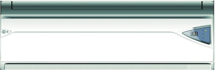


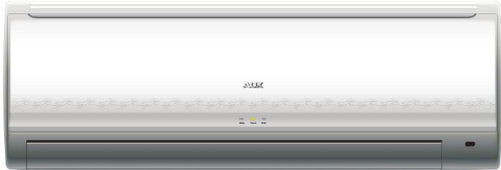
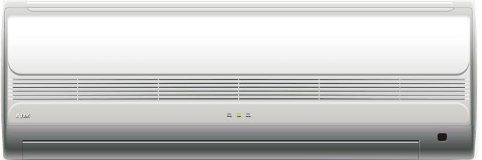

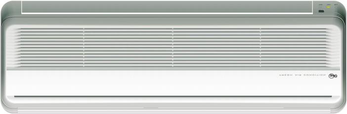
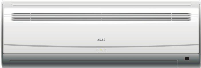
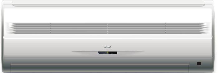
3 2.Technical Specification 2-1 Appearance 2
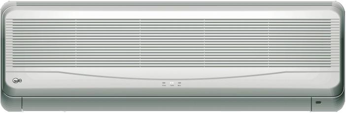
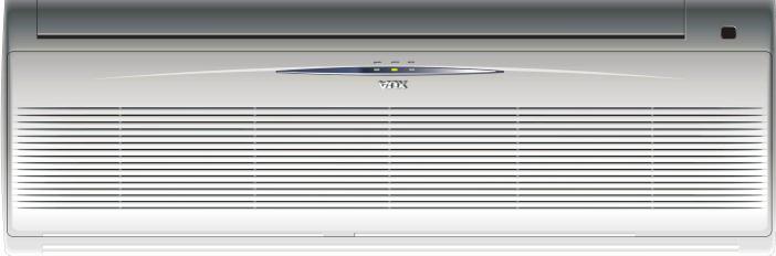
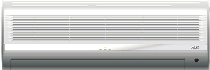
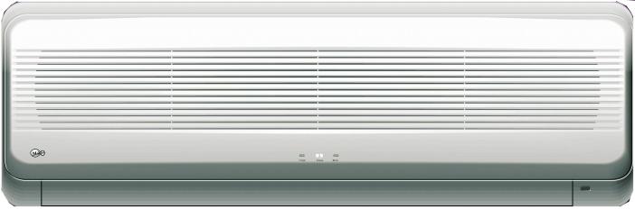
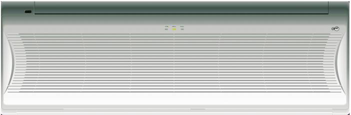
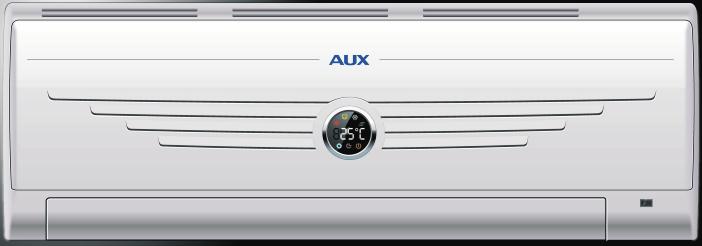
4 2.Technical Specification 2-1 Appearance(continue) INDOOR UNIT OUTDOOR UNIT 3
5 2.Technical Specification 2-2 Nomenclature 1 AUX 2 Split-type 3 Wall mounted 4 Heat pump(only for heat pump) 5 Rated cooling capacity 6 The lever code of same cooling capacity 7 Power supply 1 for 220V~/50Hz 2 for 208V-230V~/60Hz 3 for 110V~/50Hz 4 for 220V-240V~/50Hz 5 for 380V-415V-3~/50Hz 6 for 380V-3~/60Hz 7 for 208V-230V~/50Hz 8 (For more details refer to 1-1) 9 Refrigerant Default for R22 R for R407c R1 for R410a 4
6 2.Technical Specification 2-3 Product Technical Specification Diagram Performance Input Item Cooling Dehumidifying Air Flow Volume Noise Heating Power supply Rated Cooling input Heating Rated Cooling current Heating Input Cooling factor Heating Starting current Power Length supply cord Fuse capacity dimension D*W*H Net weight Connection Liquid pipe Gas Drain pipe Dimension Compressor Motor Fan motor Motor Cooling Heating Cooling Heating Rated input Model Rated input Heat exchanger(row*line Refrigerant controller Freezed oil capacity Refrigerant/Charge(g) Indoor Outdoor Indoor Outdoor Indoor Outdoor Indoor Outdoor Wall mounted Wall mounted Wall mounted Wall mounted Through-flow Plastic-sealed Capillary Rotary Axial-flow Iron-shell Through-flow Rotary Rotary Rotary Axial-flow Through-flow Axial-flow Through-flow Axial-flow Plastic-sealed Iron-shell Plastic-sealed Iron-shell Plastic-sealed Iron-shell Capillary Capillary Capillary Protection equipment Inner Inner Inner Inner Cooling test condition Heat ing test condition Max.Cooling test condition Max.Heat ing test condition Indoor unit Indoor unit Indoor unit Indoor unit Outdoor unit Outdoor unit Outdoor unit Outdoor unit 5
7 2.Technical Specification 2-3 Product Technical Specification Diagram Performance Input Item Cooling Dehumidifying Air Flow Volume Noise Heating Power supply Rated Cooling input Heating Rated Cooling current Heating Input Cooling factor Heating Starting current Power Length supply cord Fuse capacity dimension D*W*H Net weight Connection Liquid pipe Gas Drain pipe Dimension Compressor Motor Fan motor Motor Cooling Heating Cooling Heating Rated input Model Rated input Heat exchanger(row*line Refrigerant controller Freezed oil capacity Refrigerant/Charge(g) Protection equipment Indoor Outdoor Wall mounted Through-flow Plastic-sealed Capillary Rotary Axial-flow Iron-shell Inner Indoor Outdoor Wall mounted Through-flow Plastic-sealed Capillary Rotary Axial-flow Iron-shell Inner Cooling test condition Heat ing test condition Max.Cooling test condition Max.Heat ing test condition Indoor unit Indoor unit Indoor unit Indoor unit Outdoor unit Outdoor unit Outdoor unit Outdoor unit 6
8 2.Technical Specification 2-3 Product Technical Specification Diagram(continue) Performance Input Item Cooling Dehumidifying Air Flow Volume Noise Heating Power supply Rated Cooling input Heating Rated Cooling current Heating Input Cooling factor Heating Starting current Power Length supply cord Fuse capacity dimension D*W*H Net weight Connection Liquid pipe Gas Drain pipe Dimension Compressor Motor Fan motor Motor Cooling Heating Cooling Heating Rated input Model Rated input Heat exchanger(row*line Refrigerant controller Freezed oil capacity Refrigerant/Charge(g) Protection equipment Indoor Outdoor Indoor Outdoor Indoor Outdoor Indoor Outdoor Wall mounted Wall mounted Wall mounted Wall mounted Through-flow Plastic-sealed Capillary Rotary Axial-flow Iron-shell Through-flow Rotary Rotary Rotary Axial-flow Through-flow Axial-flow Through-flow Axial-flow Plastic-sealed Iron-shell Plastic-sealed Iron-shell Plastic-sealed Iron-shell Capillary Capillary Capillary Inner Inner Inner Inner Cooling test condition Heat ing test condition Max.Cooling test condition Max.Heat ing test condition Indoor unit Indoor unit Indoor unit Indoor unit Outdoor unit Outdoor unit Outdoor unit Outdoor unit 7
9 2.Technical Specification 2-3 Product Technical Specification Diagram Performance Input Item Cooling Dehumidifying Air Flow Volume Noise Heating Power supply Rated Cooling input Heating Rated Cooling current Heating Input Cooling factor Heating Starting current Power Length supply cord Fuse capacity dimension D*W*H Net weight Connection Liquid pipe Gas Drain pipe Dimension Compressor Motor Fan motor Motor Cooling Heating Cooling Heating Rated input Model Rated input Heat exchanger(row*line Refrigerant controller Freezed oil capacity Refrigerant/Charge(g) Protection equipment Indoor Outdoor Wall mounted Through-flow Plastic-sealed Capillary Rotary Axial-flow Iron-shell Inner Indoor Outdoor Wall mounted Through-flow Plastic-sealed Capillary Rotary Axial-flow Iron-shell Inner Cooling test condition Heat ing test condition Max.Cooling test condition Max.Heat ing test condition Indoor unit Indoor unit Indoor unit Indoor unit Outdoor unit Outdoor unit Outdoor unit Outdoor unit 8
10 2.Technical Specification 2-3 Product Technical Specification Diagram(continue) Performance Input Item Cooling Dehumidifying Air Flow Volume Noise Heating Power supply Rated Cooling input Heating Rated Cooling current Heating Input Cooling factor Heating Starting current Power Length supply cord Fuse capacity dimension D*W*H Net weight Connection Liquid pipe Gas Drain pipe Dimension Compressor Motor Fan motor Motor Cooling Heating Cooling Heating Rated input Model Rated input Heat exchanger(row*line Refrigerant controller Freezed oil capacity Refrigerant/Charge(g) Protection equipment Indoor Outdoor Indoor Outdoor Indoor Outdoor Indoor Outdoor Wall mounted Wall mounted Wall mounted Wall mounted Through-flow Plastic-sealed Capillary Rotary Axial-flow Iron-shell Through-flow Rotary Rotary Rotary Axial-flow Through-flow Axial-flow Through-flow Axial-flow Plastic-sealed Iron-shell Plastic-sealed Iron-shell Plastic-sealed Iron-shell Capillary Capillary Capillary Inner Inner Inner Inner Cooling test condition Heat ing test condition Max.Cooling test condition Max.Heat ing test condition Indoor unit Indoor unit Indoor unit Indoor unit Outdoor unit Outdoor unit Outdoor unit Outdoor unit 9
11 3. Operation Details 3-1 Remote Controller The closing state of remote controller: Mode display Auto Cool Dry Heat Wet Emission display Fan speed display Humidity display Anion function display Temperature display + button This button can set room temperature. Press it once,the temperature increases 1.Press it continuously, the temperature increases at the speed of 4 /s. This function is invalid when the appliance at the Fan and Auto mode. SWING button Press the button, the horizontal airflow direction plate can adjust automatically. When you have the desired wind direction, please press it again, the airflow direction plate will stop at the situation. FAN button Power display Quiet display Left/Right wind display Timer On/Off display Feeling display Sleep display Up/Down wind display Timer/Clock display Low Med High Auto Remark: The floor standing type select fan speed only from Low to High. MODE button - button This button can set room temperature. Press it once,the temperature decreases 1.Press it continuously, the temperature decreases at the speed of 4 /s. This function is invalid when the appliance at the Fan and Auto mode. Button 10
12 3. Operation Details 3-1 Remote Controller(continue) The opening state of remote controller: HEALTH SLEEP HUMIDITY FEELING/LOUVER + button This button not only can adjust clock time and the timer time but also can set room humidity. Adjusting clock time and timer time Press it once,the time increases one minute. Press it for 1 to 3 seconds, time display will increase at the speed of 2min/s. For 3 to 5 seconds, it will increase at the speed of 10min/s. For more than 5 seconds, it will increase at the speed of 10min/s. Setting room temperature and room humidity Press it once,the humidity increases 5%. HEALTH button Press this button,the LCD shows the symbol, the anion emission function of the air conditioner is started. Press the button once again, The symbol disappears, the function is cancelled at the same time. SLEEP button Press this button,the LCD shows the symbol, the sleeping function of the air conditioner is started. After 7 hours of setting this function,the air conditioner will beoff automatically. Press the button once again, The symbol disappears, the function is cancelled at the same time. This function is invalid when the appliance under the Fan mode. POWER button or POWER/QUIET button When it displays POWER button: Press this button, the fan speed reach the highest, press it again it resume the foregoing fan speed. When it displays POWER/QUIET button : POWER /QUIET TIMER/CLOCK POWER QUIET QUIT This function is only suitable for frequency variable appliance. HUMIDITY button Only under the mode of Heat and Fan, Press this button once, the LCD shows the symbol, the wetting function of the air conditioner is started. The initial humidity is 60%. Press the + or - button once,the humidity increases or decreases 5%. The setting range is 30%~60%. Press the button once again, The symbol disappears, the function is cancelled at the same time. 11
13 3. Operation Details 3-2 Operation Method TIMER/CLOCK button Setting the ON/OFF timer time When remote controller is at the on/off state, Press this button, on the LCD flickers the / off symbol. Press the + or - button to set the timer time. After finishing it, press this button again in 10 seconds to affirm. If the setting time is the same as the current time, this setting is invalid. on Press the button once more, The / symbol disappears, off the function is cancelled at the same time. Adjusting the clock time Press this button in 5 seconds Under the state of no timer setting, the LCD flickers the symbol. Press the + or - button to set the timer time. After finishing it, press this button again in 10 seconds to affirm. If not, this operation is invalid. - button This button not only can adjust clock time and the timer time but also can set room humidity. Adjusting clock time and timer time Press it once,the time decreases one minute. Press it for 1 to 3 seconds, time display will decrease at the speed of 2min/s. For 3 to 5 seconds, it will decrease at the speed of 10min/s. For more than 5 seconds, it will decrease at the speed of 10min/s. Setting room temperature and room humidity Press it once,the humidity decreases 5%. button FEELING button or LOUVER button When it displays FEELING button: Press this button can be used to set the feeling function. The LCD shows the actual room temperature when the function set and it shows the setting temperature when the function cancelled. This function is invalid when the appliance at the Fan mode. When it displays LOUVER button: Press this button, the vertical wind direction vanes can rotate automatically, when you have the desired horizontal wind direction, press it again, the vertical wind direction vanes will be stopped at the situation of your choice. 112
14 3. Operation Details 3-2 Operation Method(continue) Press the + or - button, you can set the temperature range from 16 to Press the FAN button, you can select fan speed from Low, Med, High, Auto. 2.Press the + or - button, you can set the temperature range from 16 to Press the FAN button, you can select fan speed from Low, Med, High, Auto. 2.Press the FAN button, you can select fan speed from Low, Med, High. 113
15 4. Wiring Diagram 4-1 ASW- H 24B4/E*Indoor Unit 14
16 4. Wiring Diagram 4-2 ASW- H 18B4/E* Indoor Unit Fan Motor Compressor Black Red White Red Fan Motor Capacitor Overcurrent Protector Black Yellow Compressor Capacitor Black Red Blue Yellow Green Brown Orientation Valve Blue Red Y/G Yellow Black Green Blue Brown To Indoor Unit Fan Motor Compressor Black Red White Red Yellow Fan Motor Capacitor Overcurrent Protector Black Red Compressor Capacitor Black Brown Yellow Green Red Y/G Yellow Black Green To Indoor Unit 15
17 5.Troubleshooting Guide 5-1The Foremost Inspecting Items 1.The input voltage must be within +10% tolerance of the rated Voltage. If it is not the case, the air-conditioner will probably not work normally. 2.Check the connecting cord between indoor unit and outdoor unit to see if it is properly connected. The connecting must be done according to the wiring diagram, please also notice that even different models may have the connecting cord of the same specification. Please check if the marks at the connecting terminal and the marks on the cord can match, otherwise, the air-conditioner will not work normally. 3.If the following phenomena are found, the problem is not from the air-conditioner itself. Problems The motor is heard operating but the air-conditioner dose not work when the indoor unit is powered on The compressor stops running but the indoor fan motor keeps working when it is at cooling mode with the indoor temperature higher than set temperature. The compressor works discontinuously at dehumidifying mode. The air-conditioner dose not work while the LED display is on. The compressor works discontinuously at cooling and dehumidifying mode, and the indoor fan motor slows down. Causes Since the air-conditioner is powered on, it will come to working condition as long as you press the ON/OFF button of the remote control and the signal is well received. If you turn off the air-conditioner and restart it immediately, it will return to normal in 3 minutes, after that, the air-conditioner will automatically adjust the indoor fan speed to what you set. The air-conditioner will automatically control the working of the compressor according to the inside temperature The TIMER is set with the air-conditioner,it will be in hold on condition. If the TIMER setting is cancelled, the air-conditioner will return to normal working condition. The compressor stops internally or the fan motor slows down to prevent the indoor heat exchanger from being frozen. 16
18 5.Troubleshooting Guide 5-2 No Power Display 1.Items 1 Check if the input voltage is correct? 2 Check if the AC power supply connecting is correct? 3 Check if the output voltage of the manostat L7805(IC2)is correct? 2.Trouble shooting procedure Pull out the power plug 5and replug it after some 5 seconds Does the buzzer ring? Check the connection between power supply cord and the connecting terminal, then check the fuse Does the air-conditioner start operating after pressing the ON/OFF button of the remote control? normal Is the primary voltage on Cn2 normal? Has the signal been sent Is the LED lighten? Refer to the trouble-shooting of the remote control Is the transformer OK? Is the DC voltage on the PCB board OK? Are the voltage of micro-controller #8(compressor),#2(4-way valve) and #6(outdoor fan motor)normal? Is the voltage(5vdc) of the #15 (indoor fan motor)normal? Are the voltage(ic4) of RY1(compressor), RY3(indoor fan motor)and (outdoor fan motor) normal? Replace the PCB board Is the port voltage(0vdc) of the #3 normal? Is the port voltage(5vdc) of the #7 normal? Check the connection of the compressor, indoor fan motor and outdoor fan motor Replace the Ry1, RY3,and IC4 Is the output voltage of the IC2 normal? Is the port voltage of the #27 normal? Check PCB board Replace the main PCB board Replace IC2 Are the port voltage of the #4and #5 normal? Replace the buzzer Does it run normally? Replace the micro-controller 17
19 5.Troubleshooting Guide 5-3 The Indoor Fan Motor Does Not Work 1.Items 1 Check if the indoor fan motor is connected correctly to the connector(cn8)? 2 Check if the AC input voltage is correct? 3 Check if the IC of indoor fan motor is connected correctly to the connector(cn2)? 4 Check if the capacity of indoor fan motor is connected correctly to the connector(cn8)? 2.Trouble shooting procedure Pull out the power plug and replug it after some 5 seconds Is the LED lighten? Refer to the procedure of proceeding page Is the controller output normal? The micro-controller chip fails Is the fan motor voltage satisfied? PCB fails Replace PCB The probe position PCB Cn8 #2 and #3 status The motor running Normal voltage AC 134V-160V The capacity of the fan motor does not connect CN8 Fan motor capacitor fails Replace FAC Fan motor fails Replace the indoor fan motor 18
20 5.Troubleshooting Guide 5-4 The Outdoor Unit Does Not Work 1.Items 1) Check if the input voltage is correct? 2) Check if the wire connection of the outdoor connecting terminal is correct? 2.Trouble shooting procedure Pull out the power plug and replug it after some 5 seconds Is the indoor controller normal? Check refer to the 5-2 part Is the output voltage of relay normal? Is the wire connection on the terminal correct? The relay fails The outdoor unit is abnormal Replace the relay 19
21 5.Troubleshooting Guide 5-5 The Step Motor Does Not Work 1.Items 1) Check if the input voltage is correct? 2) Check if the step motor controlling the up-down movement firmly connected to Cn2? 2.Trouble shooting procedure Pull out the power plug and replug it after some 5 seconds Start the air-conditioner with remote control Is the LED on the display board lighten? Does the louver move up and down after pressing the SWING button on the remote control? Confirm the procedure of the 5-2 part Normal Is there any voltage change between the chips #23,#22,#20,#19 The chip IC1fails Is there any voltage change between 10~13 of the the chip ULN2003AFW Drive chip IC4 (ULN2003AFW) The step motor fails 20
22 5.Troubleshooting Guide 5-6 Heating Mode Can Work, But No Hot Air Blow 1) Check if the set temperature is lower than the indoor temperature? 2) Check if the indoor PCB is connected to the terminal correctly? restarted in some 5 minutes after the above problems solved Is the chip IC1#7 voltage DC5.0V? Is the chipic1#2 voltage high? Normal The chip IC1fails The chip IC3fails Is the voltage at the connecting point of chipic4(uln2003a)low? The chip IC4 ( ULN2003A fails Is relay output normal? Replace relay(ry3) The interconnection cord or the 4-way valve is abnormal Check the interconnection cord or replace the 4-way valve Replace PCB 21
23 5.Troubleshooting Guide 5-7 Remote Control Can Not Work Trouble shooting procedure Take out the batteries and reinsert them after 5 seconds Is the LED lighten? Is there music when the ON/OFF button was pressed. Check refer to the 5-2 part Normal Is the voltage of batteries lower than 2.5V? Replace batteries Is the LCD display normal? LCD fails Is there signal when the ON/OFF button was pressed. Replace buttons Is there any change on the voltage of chip IC1? The chip fails Is there any change on the voltage Q1? Replace audion Is there any change on the voltage LED? Emission tube fails The receiver fails 22
24 5.Troubleshooting Guide 5-8 The Failure Analysis Of The Main Parts Part Measure resistance Analysis Heat exchanger Normal Environment temperature Resistance of transformer(k Abnormal Turn-off Short-cut Detecting the resistance between each connecting terminal Environment temperature Between The indoor fan motor Normal Blue yellow Main Blue red Auxillary Input Abnormal Turn-off Short-cut Detecting the voltage between the signal wire of fan motor and ground Between Voltage Normal Gray Orange Yellow Orange Abnormal voltage<0, voltage>5 is abnormal Environment temperature Step motor Normal Blue Between yellow Above 300 Around 120 Input Abnormal Turn-off Short-cut The outdoor fan motor Detecting the resistance between the red wire and every connecting end Normal When the temperature is,around and Abnormal Turn-off Short-cut 23
25 6. Explosion View And Parts List 6-1 Explosion View Of Indoor Unit E-type Explosion View Fig.1 24
26 6. Explosion View And Parts List 6-2 Parts List Of Indoor Unit MODE ASW-(H)09A4/E* ASW-(H)12A4/E*R ASW-(H)12B4/E*R1 Fig.1-01 Fig.1-02 Fig.1-03 Fig.1-04 Fig.1-04a Fig.1-04b Fig.1-04c Fig.1-04d Fig.1-04e Fig.1-05 Fig.1-06 Fig.1-07 Fig.1-08 Fig.1-09 Fig.1-10 Fig.1-11 Name Front panel Air filter Bolt cover Vane shelf assembly Vane Louver assembly Vane shelf Vane shelf foam Step motor Evaporator holder Rubber bearing mount Installation plate Clamping board for pipe Base foam Base Pipe Character Quantity 3 3 Remarks Fig.1-12 Fig.1-13 Fig.1-14 Fig.1-15 Fig.1-16 Fig.1-16a Fig.1-16b Fig.1-16c Fig.1-16d Fig.1-16e Fig.1-17 Fig.1-18 Fig.1-19 Fig.1-20 Fig.1-21 Evaporator Plastic-sealed motor Cover for electrical control box Through-flow Controller assembly Electrical control box Transformer Terminal board Main PCB Auxillary PCB Receiver of remote control Receiver window Face frame Cover offace frame Light holder for indicator 25
27 6. Explosion View And Parts List 6-3 Explosion View Of Outdoor Unit Fig.2 126
28 6. Explosion View And Parts List 6-4 Parts List Of Outdoor Unit MODE AS-(H)09A4/E* Code Name Top cover Axial-flow Outdoor motor Motor supporter Condenser Character Cold-work steel Galvanized steel Quantity Remarks Steel wire fan guard Cover for electric unit Right-hand board Capillary assembly Cold-work steel Capacitor strip Terminal board Capacitor for compressor Clamping plate for interconnection cord Holder for wire 4-way assembly Discharge pipe for compressor Suction pipe for compressor Valve board Two-way valve(dg10-i) There -way valve(dg4) Base Panel Fan guard Damping gasket Compressor Cold-work steel Cold-work steel Steel wire Rubber Wind-fending standing board Galvanized steel 127
29 6. Explosion View And Parts List 6-4 Parts List Of Outdoor Unit MODE AS-(H)12A4/E* Code Name Top cover Axial-flow Outdoor motor Motor supporter Condenser Character Cold-work steel Galvanized steel Quantity Remarks Steel wire fan guard Cover for electric unit Right-hand board Capillary assembly Cold-work steel Capacitor strip Terminal board Capacitor for compressor Clamping plate for interconnection cord Holder for wire 4-way assembly Discharge pipe for compressor Suction pipe for compressor Valve board Two-way valve(dg10-i) There -way valve(dg4) Base Panel Fan guard Damping gasket Compressor Cold-work steel Cold-work steel Steel wire Rubber Wind-fending standing board Galvanized steel 128
30 6. Explosion View And Parts List 6-4 Parts List Of Outdoor Unit MODE AS-(H)12B4/E* Code Name Top cover Axial-flow Outdoor motor Motor supporter Condenser Character Cold-work steel Galvanized steel Quantity Remarks Steel wire fan guard Cover for electric unit Right-hand board Capillary assembly Cold-work steel Capacitor strip Terminal board Capacitor for compressor Clamping plate for interconnection cord Holder for wire 4-way assembly Discharge pipe for compressor Suction pipe for compressor Valve board Two-way valve(dg10-i) There -way valve(dg4) Base Panel Fan guard Damping gasket Compressor Cold-work steel Cold-work steel Steel wire Rubber Wind-fending standing board Galvanized steel 129
31 6. Explosion View And Parts List 6-11 Explosion View Of Controller(Indoor Unit) Connection wire of display board 450 Sensor of indoor pipe 350 Sensor of indoor room 350 Fig.4 130
32 6. Explosion View And Parts List 6-12 Parts List Of Controller(Indoor Unit) Indicator shelf Receiver of remote control PP white PP white Display board Bolt 2 8 Main control board Transformer TDB-6-B4 Black Bolt 6 Spring gasket Nut Bolt Grounding wire Interconnection wire Bolt Terminal board 25HN-3 Electrical control box Bolt Clamping board Bolt Receiver board ABS(gray) Yellow/green Red Receiver board shelf Power supply cord 09:1.0mm 12:1.5mm 2 2 NO Code Name Quantity Material Remark 131
33 7.Refrigeration Cycle Diagram Indoor Unit Outdoor Unit Capillary Two-way vavle Single-way vavle Liquid side Auxillary capillary Evaporator Through-flow Condensor Axial-flow Air side Two-way vavle 4-way vavle Cool Heat Compressor The gas leak checking point Fig.5 132
34 8.Function Exposition 8-1Terminologies and their denotation TA: Indoor environment temperature TE: Indoor evaporator temperature TS: Set temperature 8-2 Forced operation button a) When the air-conditioner is on, press this button you will turn it off; when the air-conditioner is off, press this button you will turn it on and it will run at automatic mode afterwards, then the indicator light will glint for 20 seconds until it runs at your selected mode. The air-conditioner will automatically select cooling, dehumidifying or heating mode in phase with the room temperature. 1.When TA>27 C,it will be in cooling mode with the set temperature of 24 C and automatic fan speed. 2. When 20 C< TA<27 C,it will be in dehumidifying mode with set temperature of 24 C and automatic fan speed. 3.When TA<20 C,it will be in heating mode(cooling only type will be at fan mode) with the set temperature at 24 C and automatic fan speed. 4.At this mode, functions like timer, sleep, memory, negative ion, feeling function are available. Once the system, mode is set, it won t change with the room temperature, and the air-let won t run at default mode. It can be changed by remote control signals. b).press the button for 5 seconds until the buzzer rings for two intervals, then the controller will be at running-in mode for 30 minutes. 1.While at running-in mode, the air-in temperature sensor will be off duty, and the compressor will be on after 3-minute protection time. The indoor fan motor will run at automatic speed and cooling mode with the air-let position the same as that of cooling mode. 2.The anti-freeze protection and high temperature protection function will not be available. 8-3 Automatic mode When the remote control selects automatic mode to turn on the air-conditioner, The running indicator will be glinting for 20 seconds until the air-conditioner runs at set running mode, including cooling, dehumidifying, heating automatically selected in phase with room temperature. 1.When TA>27 C,it will be at cooling mode with the set temperature of 24 C and fan motor speed under the control of remote control. 2.When 20 C< TA<27 C,it will be at dehumidifying mode with the set temperature of 24 C and fan motor speed under the control of remote control. 3.When TA<20 C,it will be at heating mode(cooling only type at fan mode) with the set temperature of 24 C and fan motor speed under the control of remote control. 4.These functions like timer, sleep, memory, negative ion, I feel are available at this mode. 5.The selected mode will not change with the room temperature. It will be changed after restarting the air-conditioner or any mode switch. 133
35 8.Function Exposition 8 4 Cooling mode The temperature is controlled by pressing the + or -button on the remote control between 16 C and 32 C.You can select fan speed from Low, Med, High, Auto. The 4-way valve will keep closed at this mode, and other status are demonstrated as follows: 1.When TA-TS>1 C and it is operated after the compressor protection duration,the compressor and outdoor fan motor will be running; 2.When TA equals TS, the status will be the same as item 1; 3.When TA-TS<-1 C and it is operated after the compressor protection duration, the compressor and outdoor fan motor will be running; 4.At this mode, the fan speed can be set with remote control while the indoor fan motor will keep running; 5.When the state of TE<0 C lasts for 10s and the compressor keeps running for over 5 minutes, the indoor fan motor will run at set speed,if the compressor and outdoor fan motor are power off; when TE>7 C, it will quit this protection function; 6.At this mode, timer, sleep, memory, negative ion, I feel functions are available; 7.Once cooling mode is set, the movement of louver can be controlled by remote control; 8.Automatic fan speed control: When TA-TS>3 C,the fan motor works at high speed; When TS+1 C<TA<TS+3 C,the fan motor works at medium speed; When TA-TS<1 C,the fan motor works at low speed; If the fan speed is to be shifted from low to high, the 3-minute protection will be off, and it will be on when fan speed is to be shifted from high to low. 9.When first powered, the 3-minute compressor protection will be off and the outdoor fan motor will be running after the compressor is on for 2s;if TS is set higher than TA, the compressor will be off immediately without the protection function; 10.When TE >64 C for 10s, the compressor and outdoor fan motor are off and the compressor can be well started after TE<62 C, then the indoor fan motor will run at set speed if it is set manually when over-heat protection is on. The indoor fan will run at low speed if it is set automatic fan speed. 8-5 Dehumidifying Mode 1.The 4-way valve will keep closed at this mode with the controllable temperature between 16 C to 32 C; 2.After the duration of 3-minute protection, the compressor and outdoor fan motor will work as follows: (1).When TA>TS+2 C, the compressor and outdoor fan motor will run continuously at set speed; (2).When TS<TA<TS+2 C and the compressor and outdoor fan motor are on for 10 minutes and off for 6 minutes, then the indoor fan will be off when the compressor is off in the duration of 3-minute protection. The indoor fan will run at slight speed at under other conditions; (3).When TA<TS, the compressor and outdoor fan motor stops running, and the indoor fan motor will run at slight speed after being off for 3 minutes. Automatic fan speed control: When TA-TS>5 C, the fan motor runs at high speed; When TS+3 C<TA<TS+5 C,the fan motor runs at medium speed; When TS+2 C<TA<TS+3 C,the fan motor runs at low speed; When TS<TA<TS+2 C, the fan motor runs at slight speed; When TA<TS, the indoor fan motor will stop in the duration of 3-minute protection and run at slight speed after the duration. 134
36 8.Function Exposition 3.When first powered, the 3-minute protection will be off,and the outdoor fan motor will run after the compressor keeps running for 2s; 4.When the indoor fan motor is running, the vane can be set move freely as the that of the cooling mode; 5.When TE < 0 C for 10s and the compressor keeps running for more than 5 minutes, turn off the compressor and outdoor fan motor, the indoor fan will run at the set speed; if TE>7 C, it will quit the protection; 6.When TE > 64 C and lasts for 10s,turn off the compressor and outdoor fan motor, and the compressor can work well when TE<62 C,then the indoor fan motor will run at set speed if it is set manually; it will run at low speed if it is set automatically; 7.Timer, sleep, memory, negative ion and I feel functions are available at this mode. 8-6 Fan Mode At this mode, the outdoor fan motor will keep off while the indoor fan motor runs at set speed. You can select high, medium, low fan speed with the remote control; the movement of vane is the same as that of cooling mode; Timer, memory, negative ion functions are available at this mode. 8-7 Heating Mode The temperature can be adjusted between 16 C to 32 C by pressing the + or button on the remote control. You can select automatic, high, medium, and low speed by pressing the fan speed button. Other details are as follows: 1.When TA-3-TS<-1 C and the compressor and outdoor fan motor are turned on after the 3- minute protection duration, the indoor fan motor will run at the cold air prevention mode, and the TA displayed on the LED includes 3 C temperature compensation; 2.When TA-3-TS>-1 C and the compressor and outdoor fan motor are turned on after the 3- minute protection duration, the indoor fan motor will run at cold air prevention mode, and the TA displayed on the LED includes 3 C temperature compensation; 3.When TA-3 equals TS, the status will remain unchanged; 4.Automatic fan speed control: when TA<TS, the fan motor runs at high speed; when TS<TA<TS+2 C, the fan motor runs at medium speed; when TA>TS+2 C, the fan motor runs at low speed; When the fan speed is shifted from low to high, the 3-minute protection will be off; it will be on when the fan speed is shifted from high to low. 5.At heating mode, the movement of the vane is controlled by pressing the SWING button; 6.When first powered, the 3-minute protection function will be off and the compressor will be on after the 4-way valve keeps running for 10s, the outdoor fan motor will run after the compressor keeps running for 2s;turn TS down to TS<TA-3, then the compressor will be off immediately without the limitation of the 3-minute protection; 7.Timer, sleep, memory, negative ion, I feel functions are available at this mode; 8.When first powered, the 4-way valve will be on immediately, the compressor 10s later; when the compressor is off, the 4-way valve will be off in 2 minutes and 50s after the air conditioner is off or mode is shifted; when the compressor is off, the 4-way will be off immediately once the air-conditioner is powered off. 135
37 8.Function Exposition 9.the cold air prevention and remaining-heat expelling function The indoor fan speed is controlled by TE, the retails are as following: The cold air prevention function when the compressor is running: a)when TE is going up: when TE<25 C, the indoor fan motor will be off; when 25 C<TE<30 C, the indoor fan motor will run at slight speed; when 30 C<TE<38 C, the indoor fan motor blows quiet air-flow; when TE>38 C, the indoor fan motor run at set speed; b)when TE is going down: when TE>34 C,the indoor fan motor will run at set speed; when 28 C<TE<34 C, the indoor fan motor will blow quiet air-flow; when 23 C<TE<28 C,the indoor fan motor runs at slight speed; when TE<23 C, the indoor fan motor will be off. Copper pipe temperarure Fan motor off (650 turns) Slight speed Quiet air-flow Set fan speed Quiet air-flow Fig.6 The function when the compressor is off: a) when TE is going down when TE>25 C, the indoor fan motor runs at slight speed; when TE<25 C,the indoor fan motor will be off; b)when TE is going up when TE>28 C, the indoor fan motor runs at slight speed; when TE<28 C, the indoor fan motor will be off. (650 turns) Slight speed Fan motor off (PG motor) Fan motor off (650 turns) Slight speed Fan motor off Fig.7 136
38 8.Function Exposition The remaining-heat expelling function when the air-condition is powered off when TE>35 C, the indoor fan motor will run at slight speed; when TE<35 C, the indoor fan motor will be off, and it will keep expelling the remaining heat for no more than 10 seconds, during which the indoor fan motor will stop running immediately if TE<35 C. 10. Over-heat Protection a).heating mode when TE >57 C for 10s,the outdoor fan motor will be off; when TE>64 C for 10s,the compressor will be off; when TE<52 C and after the duration of 3-minute protection, it will return to normal. b).the temperature protection is only available when the TE sensor works well. 8-8 The accessorial electric heater function a).at heating mode, this function can only available if the following conditions are satisfied: (1)TE<48 C (2)TA<22 C (3)TS-TA>3 C 4.The compressor keeps running at heating mode foe 4 minutes. b).it will quit the function if one of the following conditions is satisfied: (1)TA>22 C (2)S-TA<2 C (3)TE>52 C c)either compressor or indoor fan motor does not work, it will quit the function automatically. d)it will quit the function when shifting modes or cutting off the power. e)if the function is quitted while the compressor is running, it can only be restarted after 1 minute. 8-9 Intelligent defrost function a).this function can only be available if all the following conditions are satisfied. When defrosting, the sleep indicator will keep glinting: 1.1)the outdoor fan motor is in over-heat protection and stops running; 2 the outdoor fan motor is restarted to work for at least 10 minutes; 3) the compressor keeps running totally over 45 minutes; 4)the compressor keeps running continuously for at least 20 minutes; 5)TE<48 C 2.1)When the heating mode lasts for 5 minutes or 5 minutes after the defrosting, try to capture the maximum difference between TE and TA. The difference should be more than 5C and last for at least 3 minutes; 2)the compressor keeps running continuously for at least 5 minutes; 3)the compressor runs totally for at least 45 minutes; 4)TE<48 C Remark: if fan speed modification is applied, the temperature will be modified down for -1 C when the indoor fan motor lowers a grade; and up for 1 C when it rises a grade. 137
39 8.Function Exposition 3.1)the compressor runs totally for at least 3 hours; 2)the compressor keeps running for at least 20 minutes; 3)the difference between TE and TA is less than 16 C; 4.1)the difference between TE and TA is less than 16 C and lasts for 5 minutes; 2).the compressor runs totally for at least 45 minutes; 3).the compressor keeps running for at least 20 minutes Please record the TE before defrosting. After the defrosting and the compressor keeps running for 10 minutes, compare the TE with the recorded TE, if the latter is not 3 C higher than the former, then the next defrosting can not be achieved under this condition until mode is shifted, restarting to heating or after being defrosted. 5.Record the time after the air-conditioner is set over-heat protection, carry out another defrosting after 2 hours. b)the function will be quitted if one of the following conditions is satisfied: 1)intelligent defrosting time is longer than 9 minutes 2).4 minutes after the defrosting, if TE is above 0 C and go up 2 C in 10s 3).5 minutes after the defrosting, if TE>5 C; 4).Check the compressor current after the it runs for 1 minutes, it should be higher than 6A (ASW-H12A and ASW-H12B should be higher than 8A) and lasts for 5s Sleeping function This function is available at automatic, cooling, dehumidifying, and heating modes. Once the function is on, the indoor fan speed will go down automatically for one rate, and the sleep indicator will be lighten. For cooling mode, the set temperature will go up automatically for 1 C after 1 hour; for heating mode, it will go down for 2 C after 1 hour. The air-conditioner will be powered off automatically after 7 hours. Once in the sleep function, modes can be shifted, and every shift will conceal the function. If you press the + button, the air-conditioner will run at the temperature of newly-set temperature+amended temperature. On the sleeping mode, the sleep function will be concealed if the SLEEP button, MODE button are pressed or the air-conditioner is powered off. Sleeping function at cooling mode Set temperature Original set temperature Go up for 1 C Another 1 C 1h 2h 7h(Quit the sleeping function and powered off automatically) 138
40 8.Function Exposition Sleeping function at cooling mode Set temperature Original set temperature Go down for 2 C Another 2 C 1h 2h 7h(Quit the sleeping function and powered off automatically) 8 11 Timer Function The longest timing interval is 24 hours( 1minute as the unit), and once the timer is set, it will not be changed even modes are shifted and the indicator will be lighten. 1.TIMER off This can only be set when the air-conditioner is running, and the timing scope is 1min-24 hours, it will automatically powered off once set. 2.TIMER on This can only be set when the air-conditioner is off, and the timing scope is 1min-24 hours, it will automatically run once set. The original timer and sleep function will be automatically cancelled if the air-conditioner is powered on or off again Self-inspection Press the forced switch to power the air-conditioner on, the buzzer rings two times, signalling the inspection process: The electric heater is on, the indoor fan runs at high speed, and the LED and there indicators are lighten for 1s.The LED will display in turn for 1s,then the running indicator for 1s,TIMER indicator for 1s, SLEEP indicator for 1s and the each phase of the step motor electrified for 1s. Then the indoor fan motor runs at both low and medium speed for 1s, the compressor moves for 1s,the 4-way valve for 1s,the outdoor fan motor for 1s,the negative ion for 1s and then the buzzer rings, the electric heater runs for 30s and then stops. Then the air-conditioner comes to the hold-on mode, the self-inspection is completed Failure Indicating When the air-conditioner fails, the LED on the display plate will display the relevant failure code. The details are as follows: Causes Display Failures Pg abnormal feedback Ta abnormal Te abnormal Stop running Stop running Stop running 139
41 8.Function Exposition If no impulse signal feedback from the indoor motor 10 second after it was filled with voltage, the controller will turn off automatically, 30 second later it will restart and impose voltage to the indoor motor again, if still no impulse signal were detected the controller will hold on, at the same time the digital tube will show the malfunction code as E4, if you turn off the power, the malfunction display will disappear definition of louver waving angle (Fig. 8) ASW-H18A4/E# means the waving angle of E series wall mounted type air conditioner (excluding ASW-H18A4/E# ): 1. When filled with power, the louver will completely closed, the waving speed is 22 /s; 2. After the unit was turn on, the louver will unwind, and it will swing to the original position when heating, it will stop at the 5th position (pic 3) ; While cooling it will swing to the 2nd position (pic 3). 3. The louver button on the remote control can be setting as free waving and manual waving; 4. Free waving, when heating the waving scope is 50, from 3 to 5 (as pic 3), when cooling the waving scope is 50, from2 to 4 (as pic 3); the waving speed is 5.5 /s; 5. After the unit was turn on, if the louver was setting as unwave by remote control,the waving angle will positioning to a proper height according to different mode, e.g. cooling mode was showed as 2nd position (pic 3), while heating mode was showed as 5th position (pic 3), after the fan motor was opened it will resume waving automatically; if the remote control set it as, manual waving the waving angle won t change; 6. After the fan motor stop running the louver will close automatically; 7. When the force button was pressed the unit will run into automatic mode, the louver will open after the system running, heretofore the louver stop at the norm cooling position. Position Position 2 Cooling datum mark Position 3 the dead position of the swinging vane Position 6 (louver is all open) Position 4 the dead position of the swinging vane Position 5 heating datum mark Fig
42 8.Function Exposition 8-15 Fan speed option The resistance of blowing option as below High Midium Low The instruction of controller of E series wall mounted type Remark: Quiet blowing speed, heating mode is 850r/min, while non heating mode is 800r/min; low speed is 650r/min. According to different remote control, the controller add up some high efficiency blowing, which will add 100r/min on the basis of high speed blowing Pre-leave function The functions hereunder existing in the chip, if there is correspond hardware the function will be available, e.g.: The power break off memory function need the E2 chip, I feel function need corresponding remote control, negative ion need corresponding relay. 1. The power break off memory function 1) setting: After the controller was filled with power, please press the sleeping button 10 consecutive times in 5s, if it s successfully setting, the buzzer will ring 4 consecutive times, if you want to quit such function doing the same thing. The buzzer will ring 2 consecutive, times to show it s cancel; 2) The power break off memory can remember: running mode, blowing speed setting, TS, negative ion, waving state and turn on/off situation. 3) Once the power break off memory function was setting, if the units was turn off naturally, there will no time-elapse protection, while it was turned off abnormally the compressor will have 3min time-elapse protection when restart. 2. The I feel function 1). Setting: press the conresponding button on the remote control, the controller will receive the temperature from the sensor in the remote control????????????????????? 141
43 8. 2) Quit the function a) press the corresponding button on the remote control one more time; b) Aim at the receiver of the controller, the remote control will send signal to the controller per 3s, if the controller can, t receive signal from remote control, this function will quit automatically, TA will control temperature according to the TA sensor in the controller. P.S.: When the I feel function start the main control board will stop detect the TA sensor. 3. The negative ion function When the indoor fan motor running, press the negative ion button on the remote control, the relay will open up and there is negative ion output, while the button was pressed, this function will be quit 142
44
TAC-09CS/K TAC-12CS/K TAC-18CS/K TAC-24CS/K TAC-07CHS/K TAC-09CHS/K TAC-12CHS/K TAC-18CHS/K TAC-24CHS/K
 TCL WALL MOUNTED SPLIT-TYPE AIR CONDITIONERS SERVICE MANUAL No.TE040427 Models TAC-07CS/K TAC-09CS/K TAC-2CS/K TAC-8CS/K TAC-24CS/K TAC-07CHS/K TAC-09CHS/K TAC-2CHS/K TAC-8CHS/K TAC-24CHS/K CONTENTS. IMPORTANT
Technical Manual of AUX Air Conditioner CONTENTS. Product Specification...1. Refrigeration Diagram...3. Introductions of Installation.
 CONTENTS Product Specification......1 Refrigeration Diagram....3 Introductions of Installation. 6 Remote Controller Introductions..13 Brief Introduction for Usage...21 Wiring Diagram....27 Troubleshooting
TREO SERVICE MANUAL. Models WALL MOUNTED SPLIT-TYPE AIR CONDITIONERS. No.TE CONTENTS
 TREO WALL MOUNTED SPLIT-TYPE AIR CONDITIONERS SERVICE MANUAL No.TE121112 Models CS-H09UT1 CS-H18UT1 CS-H12UT1 CS-H24UT1 CONTENTS 1. IMPORTANT NOTICE 2 2. OPERATION DETAILS 3 3. WIRING DIAGRAM 11 4. EXPLOSION
TAC-09CHSA/*** TAC-12CHSA/*** TAC-18CHSA/*** TAC-24CHSA/*** SERVICE MANUAL WALL MOUNTED SPLIT-TYPEAIR CONDITIONERS. No.TE1307.
 WALL SPLIT-TYP WALL MOUNTED SPLIT-TYPEAIR CONDITIONERS MOUNTED SERVICE MANUAL No.TE1307 Models: TAC-09CHSA/*** TAC-12CHSA/*** TAC-18CHSA/*** TAC-24CHSA/*** CONTENTS: 1. IMPORTANT NOTICE 2. OPERATION DETAILS
SPLIT TYPE AC AND MULTI SPLIT AC SERVICE MANUAL
 SPLIT TYPE AC AND MULTI SPLIT AC SERVICE MANUAL Model:PAC9039/GPAC9039/PAC12519/PMA1212/PAC12039/ PAC13039/PAD12060EN/PAD12080A/GPAC12039/PAC18039/ PAD18060EN/GPAC18039/PAC24039/PAD24060EN/GPAC24039/ PAC30039/PAC36039
KSIA SERIES SPLIT TYPE ROOM AIR CONDITIONER. For Split Wall Mounted Series R410a Inverter Model Type For F
 KSIA SERIES ro le oo SPLIT TYPE ROOM AIR CONDITIONER For Split Wall Mounted Series R410a Inverter Model Type For F KSIA009-H216-I / KSIA009-H216-O KSIA012-H216-I / KSIA012-H216-O KSIA018-H216-I / KSIA018-H216-O
CONTENTS. Product Specification..1 Refrigeration Diagram.. 3 Wiring Diagram.6 Troubleshooting Guide...9
 E E e i e M nu l I OO I O I IO or it ount d ri In rt r od or I I I O I I I O I I I O I I I O le se Please read e this t is owner o ne s manual s m nu l carefully e ull and n t o ou l thoroughly before
Operating Functions Temperature Parameters
 Operating Functions Temperature Parameters Room set temperature (T set) Room ambient temperature (T amb) Fundamental Functions After powered on, no matter when the compressor is started, the time interval
BTU Units WORKING PROGRAM MANUAL
 9000-24000BTU Units WORKING PROGRAM MANUAL SUMMARIZE FUNCTIONS & OPERATION MODES TIMER, SLEEP MODE, FAN SPEED PROTECTION FUNCTIONS EMERGENCY SWITCH TEST GUIDE MEMORY FUNCTIONS SUMMARIZE The Operation Modes
TCL SERVICE MANUAL. Models WALL MOUNTED SPLIT-TYPE AIR CONDITIONERS. No.TE CONTENTS
 TCL WALL MOUNTED SPLIT-TYPE AIR CONDITIONERS SERVICE MANUAL No.TE031229 Models TAC-07CS/K TAC-09CS/K TAC-12CS/K TAC-18CS/K TAC-24CS/K TAC-07CSC/K TAC-09CSC/K TAC-12CSC/K TAC-18CSC/K TAC-24CSC/K TAC-07CHS/K
Ductless Split Air Conditioner
 Ductless Split Air Conditioner Service Manual Indoor HSU09VHG(DB)-W HSUVHG(DB)-W HSU8VHH(DB)-W HSUVHG(DB)-W Outdoor HSU09VHG(DB)-G HSUVHG(DB)-G HSU8VHH(DB)-G HSUVHG(DB)-G Design may vary by model number.
GMSG OWNER S MANUAL SPLIT-SYSTEM ROOM AIR CONDITIONER CONTENTS
 GMSG OWNER S MANUAL SPLIT-SYSTEM ROOM AIR CONDITIONER CONTENTS SAFETY PRECAUTIONS 3 PARTS NAMES 5 OPERATING TEMPERATURE 6 MANUAL OPERATION 7 ADJUSTING AIRFLOW DIRECTION 8 HOW THE AIR CONDITIONER WORKS
WORKING PROGRAM. Heating dehumidifying cooling T 27
 I. Functions and Operation Modes WORKING PROGRAM The operation modes of the unit run like the following: Auto cooling dehumidifying heating --------------------------------------- Note: Cooling only unit
AIR-CONDITIONER REMOTE CONTROLLER INSTRUCTIONS
 AIR-CONDITIONER REMOTE CONTROLLER INSTRUCTIONS SET TEMPERATURE( ) AUTO 自动 COOL DRY HEAT FAN SPEED 制冷 TURBO HIGH MID LOW AUTO 制热 HOUR ON OFF SET ROOM C ON HEALTH LOCK SLEEP DISPLAY Anti-FUNGUS SET ON/OFF
Wired Remote Controller XK19 and Wireless Remote Controller YT1F
 and Wireless Remote Controller YT1F Owner's Manual Commercial Air Conditioners Thank you for choosing Commercial Air Conditioners, please read this owner s manual carefully before operation and retain
Portable Air Conditioner USER MANUAL
 AC12 AC12HP Portable Air Conditioner USER MANUAL Thank you for choosing this innovative Amcor air conditioner. We suggest that you keep this manual in a safe place for future reference. It describes the
Service Manual & Installation Manual
 GE Consumer & Industrial Appliances Service Manual & Installation Manual Split System Air Conditioner Model numbers: GE AIR F24 GE AIR F34 GE AIR F41 1 2 3 Introduction and Features Model Remarks GE AIR
Ductless Split Air Conditioner
 Ductless Split Air Conditioner Service Manual Indoor AW09ESVHA AWESVHA AW8ESVHA AWESVHA Outdoor U09ESVHA UESVHA U8ESVHA UESVHA Design may vary by model number. Please read this manual before using the
TROUBLESHOOTING TROUBLESHOOTING. Indoor unit EEPROM parameter error. Indoor / outdoor units communication error. Zero-crossing signal detection error
 www.olmo-comfort.com TROUBLESHOOTING When below list for identification of error code occurs, please turn off air conditioner and disconnect power, and then contact the qualified professionals for service.
Warning: 230V / 1ph / 50Hz V / 3ph / 50Hz. Remarks: Make sure that you have enough power. (See page 15 Cable table)
") 1 2 Warning: - Do not place your hand or any other objects into the air outlet and fan. It could damage the heat pump and cause injuries; - In case of any abnormality with the heat pump, cut off the power
1 2 Warning: - Do not place your hand or any other objects into the air outlet and fan. It could damage the heat pump and cause injuries; - In case of any abnormality with the heat pump, cut off the power
SPLIT TYPE ROOM AIR CONDITIONER. WALL MOUNTEDtype INVERTER. Models Indoor unit Outdoor unit AOU 9RLFW1 AOU12RLFW1 ASU 9RLF1 ASU12RLF1 R410A
 SERVICE INSTRUCTION SPLIT TYPE ROOM AIR CONDITIONER WALL MOUNTEDtype INVERTER Models Indoor unit Outdoor unit ASU 9RLF ASURLF AOU 9RLFW AOURLFW R40A CONTENTS. DESCRIPTION OF EACH CONTROL OPERATION. COOLING
C&H NORDIC Commercial 4 SERVICE MANUAL
 C&H NORDIC Commercial 4 SERVICE MANUAL CONTENTS PRODUCT...3 1 MODELS LIST... 3 1.1 Outdoor Unit.... 3 1.2 Indoor Unit.... 4 2 PRODUCT DATA.... 5 2.1 Product Data of Indoor Unit... 5 2.2 Operation Range...
PDA20DX Air Purifying Dehumdifier Manual
 PDA20DX Air Purifying Dehumdifier Manual Index Important Safe Guards Ambient Environment For Operating Components Diagrams---Parts Names Operating Introduction---How to operate - Functions of Control Panel
WALL MOUNTED type SPLIT TYPE ROOM AIR CONDITIONER CONTENTS. Models
 SPLIT TYPE ROOM AIR CONDITIONER WALL MOUNTED type Models Indoor unit ASY9USCCW ASY9USCCW ASY12USCCW Outdoor unit AOY9USCC AOY9UFCC AOY12USCC CONTENTS SPECIFICATIONS................................... 1
USER MANUAL SILENT16 PORTABLE AIR CONDITIONER
 USER MANUAL SILENT16 PORTABLE AIR CONDITIONER Thank you for choosing electriq Please read this user manual before using this innovative Air Conditioner and keep it safe for future reference. Visit our
Большая библиотека технической документации каталоги, инструкции, сервисные мануалы, схемы.
 Air Conditioner Service Manual Большая библиотека технической документации http://splitoff.ru/tehn-doc.html каталоги, инструкции, сервисные мануалы, схемы. 2 Model: AC-S10CG 3 Content Technical specification..
15,000 BTU Portable Air Conditioner
 Instruction Manual 15,000 BTU Portable Air Conditioner Model: HYAC15 READ AND SAVE THESE INSTRUCTIONS Please read and follow the instructions in this user manual even if you feel you are familiar with
SPLIT TYPE AIR CONDITIONER WAS-09HSTD WINTAIR
 SPLIT TYPE AIR CONDITIONER SERVICE MANUAL WAS-09HSTD WINTAIR Type of contents 1. OPERATION RANGE 2. SPECIFICATION 3. INSTALLATION 4. REFRIGERANT FLOW DIAGRAM 5. ELECTRICAL DATA 6. CONTROL MODE 7. TROUBLE
COMPACT PORTABLE AIR CONDITIONER USER MANUAL
 COMPACT PORTABLE AIR CONDITIONER USER MANUAL Thank you for choosing ElectriQ Please read this user manual before using this innovative Air Conditioner and keep it safe for future reference. Visit our page
R410A. WALL MOUNTEDtype INVERTER SPLIT TYPE ROOM AIR CONDITIONER. Models Indoor unit Outdoor unit AO*G09LTCN AO*G12LTCN AO*G14LTCN
 SERVICE INSTRUCTION SPLIT TYPE ROOM AIR CONDITIONER WALL MOUNTEDtype INVERTER Models Indoor unit Outdoor unit AS*G09LTCB AS*GLTCB AS*G4LTCB AO*G09LTCN AO*GLTCN AO*G4LTCN R40A CONTENTS. DESCRIPTION OF EACH
SERVICE INSTRUCTION R410A. WALL MOUNTEDtype INVERTER SPLIT TYPE ROOM AIR CONDITIONER. Models Indoor unit Outdoor unit AOU9RLS2H AOU12RLS2H AOU15RLS2H
 SERVICE INSTRUCTION SPLIT TYPE ROOM AIR CONDITIONER WALL MOUNTEDtype INVERTER Models Indoor unit Outdoor unit ASU9RLS ASURLS ASU5RLS AOU9RLSH AOURLSH AOU5RLSH R40A CONTENTS. DESCRIPTION OF EACH CONTROL
Mobile Type Air Conditioner
 Mobile Type Air Conditioner 1. Features 2. Specification 3. Wiring diagram 4. Trouble shooting 5. Electronic function 36 1. Features 1.1The currently manufactured mobile air conditioners include the following
USER MANUAL SILENT12 PORTABLE AIR CONDITIONER
 USER MANUAL SILENT12 PORTABLE AIR CONDITIONER Thank you for choosing electriq Please read this user manual before using this innovative Air Conditioner and keep it safe for future reference. Visit our
R410A. WALL MOUNTEDtype INVERTER SPLIT TYPE ROOM AIR CONDITIONER. Models Indoor unit Outdoor unit AOYG07LEC AOYG09LEC AOYG12LEC AOYG14LEC
 SERVICE INSTRUCTION SPLIT TYPE ROOM AIR CONDITIONER WALL MOUNTEDtype INVERTER Models Indoor unit Outdoor unit ASYG07LECA ASYG09LECA ASYG12LECA ASYG14LECA AOYG07LEC AOYG09LEC AOYG12LEC AOYG14LEC R410A CONTENTS
Before using your air conditioner, please read this manual carefully and keep it for future reference. ACDC12B
 Before using your air conditioner, please read this manual carefully and keep it for future reference. ACDC12B INVERTER SPLIT-TYPE ROOM AIR CONDITIONER User and Remote Control Manual Read This Manual Inside
Technical Support Division GD CHIGO HEATING & VENTILATION EQUIPMENT CO., LTD.
 Technical Support Division 2017-4-25 New CMV System - Floor ceiling Indoor Unit 1 1. External appearance 2. Nomenclature 3. Specifications 4. Dimensions 5. Service space 6. Piping diagram 7. Wiring diagram
Local Air Conditioner
 Local Air Conditioner Thank you for selecting this air-conditioner. Please keep this User s Manual for future reference. Read the User s Manual carefully before operating this unit. IMPORTANT SAFEGUARDS
SERVICE INSTRUCTION R410A. WALL MOUNTEDtype SPLIT TYPE ROOM AIR CONDITIONER INVERTER. Models Indoor unit Outdoor unit AO* R09LECN AO* R12LECN
 SERVICE INSTRUCTION SPLIT TYPE ROOM AIR CONDITIONER WALL MOUNTEDtype INVERTER Models Indoor unit Outdoor unit AS* A09LEC AS* A12LEC AO* R09LECN AO* R12LECN R410A CONTENTS 1. DESCRIPTION OF EACH CONTROL
Portable Air Conditioner
 Owner s Manual Portable Air Conditioner Model PCMB-12000E / PCMB-12000EH It is important that you read these instructions before using your new purchase and we strongly recommend that you keep them in
SERVICE MANUAL 42QHF009DS* 42QHF012DS* 42QHF018DS* 42QHF022DS* 38QUS009DS* 38QUS012DS* 38QUS018DS* 38QUS022DS* Indoor unit.
 SERVICE MANUAL Indoor unit Outdoor unit 42QHF009DS* 42QHF012DS* 42QHF018DS* 42QHF022DS* 38QUS009DS* 38QUS012DS* 38QUS018DS* 38QUS022DS* INDEX PART1 GENERAL INFORMATION PART2 ELECTRICAL DIAGRAM PART3 TROUBLE
Change for Life. Service Manual
 Change for Life Service Manual Models: GWH09QB-K3DNA1G GWH09QB-K3DNA2G GWH09QB-K3DNA5G GWH09QB-K3DNB2G GWH09QB-K3DNB4G GWH09QB-K3DNB6G GWH12QC-K3DNA1G GWH12QC-K3DNA2G GWH12QC-K3DNA5G GWH12QC-K3DNB2G GWH12QC-K3DNB4G
SERVICE Manual FREE JOINT MULTI AIR CONDITIONER
 FREE JOINT MULTI AIR CONDITIONER INDOOR UNIT MH020FPEA MH023FPEA MH026FPEA MH035FPEA MH052FPEA MH8VP2-09 MH9VP2-07 MH9VP2-2 MH026FKEA MH035FKEA MH052FDEA OUTDOOR UNIT MH8VP2X MH9VP2X MH052FXEA2 MH068FXEA4
OWNER S MANUAL HIGH WALL INVERTER. (English) (MSHVD1S SERIES)
 (MSHVD1S SERIES)") OWNER S MANUAL HIGH WALL INVERTER (English) (MSHVD1S SERIES) IMPORTANT As with any product that has moving parts or is subject to wear and tear, it is VERY IMPORTANT that you maintain your air conditioner
OWNER S MANUAL HIGH WALL INVERTER (English) (MSHVD1S SERIES) IMPORTANT As with any product that has moving parts or is subject to wear and tear, it is VERY IMPORTANT that you maintain your air conditioner
AIR CONDITIONING SYSTEMS WALL MOUNTED UNIT
 AIR CONDITIONING SYSTEMS WALL MOUNTED UNIT SERVICE MANUAL MODELS: L4VI32-18/L4VO32-18 L4VI32-24/L4VO32-24 ENGLISH Table of Contents Part Ⅰ : Technical Information...1 1. Summary...1...2...3 2.2 Operation
SERVICE INSTRUCTION R410A. WALL MOUNTEDtype INVERTER SPLIT TYPE ROOM AIR CONDITIONER. Models Indoor unit Outdoor unit AO*G24LFL AO*G24LFCC AO*G30LFT
 SERVICE INSTRUCTION SPLIT TYPE ROOM AIR CONDITIONER WALL MOUNTEDtype INVERTER Models Indoor unit Outdoor unit AS*G4LFCA AS*G4LFCC AS*G0LFCA AO*G4LFL AO*G4LFCC AO*G0LFT R40A CONTENTS. DESCRIPTION OF EACH
OWNER S MANUAL DLFCAB / DLFCHB / DLFDAB / DLFDHB High Wall Ductless System Sizes 09 36
 OWNER S MANUAL DLFCAB / DLFCHB / DLFDAB / DLFDHB High Wall Ductless System Sizes 09 36 TABLE OF CONTENTS PAGE SAFETY PRECAUTIONS... 2 GENERAL... 2 INDOOR UNIT PART NAMES... 3 REMOTE CONTROL PART NAMES...
OWNER S MANUAL. R 410A Ductless Split System Air Conditioner and Heat Pump
 R 410A Ductless Split System Air Conditioner and Heat Pump Models DLC4(A/H) Outdoor Unit, DLF4(A/H) Indoor Unit Sizes 9K, 12K, 18K, 24K, 30K and 36K Please read the operating instructions and safety precautions
CLIM9000CE PORTABLE AIR CONDITIONER USER MANUAL
 CLIM9000CE PORTABLE AIR CONDITIONER USER MANUAL Please read this user manual before using this innovative Air Conditioner and keep it safe for future reference. SAFETY INSTRUCTIONS Important! Carefully
40KMC KMQ
 40KMC------301 40KMQ------301 OWNER S MANUAL Split system Global cassette indoor unit IR Remote Control Room Controller Zone Manager The unit can be used with infrared Remote Control, with the Carrier
1. Features Specification Dimensions Refrigeration cycle diagram Operation limits
 GLORY (ECO) STAR SERIES 1. Features 60 2. Specification 61 61 3. Dimensions 67 67 4. Refrigeration cycle diagram 70 70 5. Operation limits 71 6. Wiring diagram 72 7. Troubleshooting 80 8. Electronic function
OWNER S MANUAL ENGLISH REMOTE CONTROLLER R05 YDS-R
 ENGLISH YDS-R05-0408 OWNER S MANUAL REMOTE CONTROLLER R05 Please read this installation manual carefully before installing your air conditioner. Please keep this manual in a safe place for future reference.
DAEWOO SERVICE MANUAL DSC-1245FL DSC-1285FL DSC-1285FLH. Models WALL MOUNTED SPLIT-TYPE AIR CONDITIONERS. No CONTENTS
 DAEWOO WALL MOUNTED SPLIT-TYPE AIR CONDITIONERS SERVICE MANUAL No.20160824 Models DSC-1245FL DSC-1285FL DSC-1285FLH CONTENTS 1. IMPORTANT NOTICE 2. PRODUCT DIMENSIONS 3. REFRIGERATION CYCLE DIAGRAM 4.
High Wall Split Air Conditioners 53QHCT KHCT
 Miraco MISR REFRIGERATION & AIR CONDITIONING MFG. CO. R22 220-240V ~ 50Hz 1Ph High Wall Split Air Conditioners 53QHCT 12-18-24 53KHCT 12-18-24 Heat Pump Cool Only OWNER S MANUAL Carrier is committed to
Part 5. Troubleshooting. 1. Normal Air Conditioner Phenomenon Air Conditioner Protection in Common
 Part 5 1. Normal Air Conditioner Phenomenon... 1611 2. Air Conditioner Protection in Common... 1611 3. Malfunction Code and... 162 160 1. Normal Air Conditioner Phenomenon 1.1 When outdoor unit appears
II PCV1 Features
 II-15-24-43-PCV1 FLOOR STANDING CABINET TYPE HEAT PUMP COOLING CAPACITY: 4,6 kw - 12,6 Kw HEATING CAPACITY: 4,7 kw - 13,0 kw R410A Scroll The new Interklima floor standing CABINET type heat pumps are the
SPLIT - TYPE ROOM AIR CONDITIONER
 Before using your air conditioner, please read this manual carefully and keep it for future reference. SPLIT - TYPE ROOM AIR CONDITIONER Read This Manual Inside you will find many helpful hints on how
COLDWAVE. Portable Air Conditioner. Model MPPD-12CRN BTU/h 110V/1Ph/60Hz R410A
 COLDWAVE Portable Air Conditioner 12000 BTU/h 110V/1Ph/60Hz R410A Model MPPD-12CRN1 Features: 4 Speed Fan Ion Generator Sleep Mode Timer Auto/Cool/Dry Mode Swing Function Follow Me Temperature Sensor Swing
TECENICAL DATA. Model No. HSU-09HEA03/R2(DB)-I HSU-12HEA03/R2(DB)-I HSU-18HEA03/R2(DB)-I HSU-24HEA03/R2(DB)-I. Wall mounted Type. DC Inverter E-Series
-I HSU-12HEA03/R2(DB)-I HSU-18HEA03/R2(DB)-I HSU-24HEA03/R2(DB)-I. Wall mounted Type. DC Inverter E-Series") TECENICAL DATA Order No.AC0902T003V0 Wall mounted Type DC Inverter E-Series Model No. HSU-09HEA03/R2(DB)-I HSU-12HEA03/R2(DB)-I HSU-18HEA03/R2(DB)-I HSU-24HEA03/R2(DB)-I 9K 12K 18K 24K 09K 12K 18K WARNING
TECENICAL DATA Order No.AC0902T003V0 Wall mounted Type DC Inverter E-Series Model No. HSU-09HEA03/R2(DB)-I HSU-12HEA03/R2(DB)-I HSU-18HEA03/R2(DB)-I HSU-24HEA03/R2(DB)-I 9K 12K 18K 24K 09K 12K 18K WARNING
SERVICE MANUAL ROOM AIR CONDITIONER TAN/TAG-A28FWIS TAN/TAG-A32FWIS CONTENTS
 SERVICE MANUAL ROOM AIR CONDITIONER TAN/TAG-A28FWIS TAN/TAG-A32FWIS CONTENTS SPECIFICATION... 1 FUNCTIONS... 5 SERVICE FUNCTION EXPLANATION... 7 OPERATION DETAILS... 8 TROUBLESHOOTING GUIDE... 13 PERFORMANCE
SILENT 12 PORTABLE AIR CONDITIONER USER MANUAL
 SILENT 12 PORTABLE AIR CONDITIONER USER MANUAL Thank you for choosing ElectriQ Please read this user manual before using this innovative Air Conditioner and keep it safe for future reference. Visit our
Registrate by scanning. Add: North Carolina USA
 ALORAIR Registrate by scanning E-mail: sales@alorair.com Add: North Carolina USA Table of Contents Introduction Introduction... 01 Specifications... 01 Notice priorities... 02 Operation Panel... 03 Preparing
Owner's Manual. Owner's Manual. Air Conditioners
 Wired Controller XK76 Owner's Manual Owner's Manual Air Conditioners Thank you for choosing Air Conditioners, please read this owner s manual carefully before operation and retain it for future reference.if
Floor-Standing Type(E Series)
") Floor-Standing Type(E Series) Model: MFE-60CE, MFE-60AE Part 1. Product Features With a spiral shape, the computer-aided simulation designed air passage system can efficiently reduce noise. The Soft touch
Floor-Standing Type(E Series) Model: MFE-60CE, MFE-60AE Part 1. Product Features With a spiral shape, the computer-aided simulation designed air passage system can efficiently reduce noise. The Soft touch
Service Manual. Room Air Conditioner Split Wall-Mounted Type. Applies to: HSG-09HRN1 HSG-12HRN1 HSG-18HRN1 HSG-24HRN1
 Service Manual Room Air Conditioner Split Wall-Mounted Type Applies to: HSG-09CRN1 HSG-12CRN1 HSG-18CRN1 HSG-24CRN1 HSG-09HRN1 HSG-12HRN1 HSG-18HRN1 HSG-24HRN1 NOTE: Please read this first before servicing
Air Conditioner CONTENTS
 ORDER NO. MAC0509068C2 Air Conditioner CS-F24DD1E5 CU-B24DBE5 CS-F28DD1E5 CU-B28DBE5 CS-F28DD1E5 CU-B28DBE8 CS-F34DD1E5 CU-B34DBE5 CS-F34DD1E5 CU-B34DBE8 CS-F43DD1E5 CU-B43DBE8 CS-F50DD1E5 CU-B50DBE8 CONTENTS
Model No. GB-PAC-08E4. 8,000 BTU Portable Air Conditioner Operating Instructions
 Model No. GB-PAC-08E4 8,000 BTU Portable Air Conditioner Operating Instructions Thank you for choosing a Soleus Air Powered by Gree Portable Air Conditioner. This owner s manual will provide you with valuable
Utopian Split A/C. Thank you for purchasing this quality Split A/C system!
 Utopian Split A/C Thank you for purchasing this quality Split A/C system! Please read through this manual completely, and keep it in case you need to reference the information in the future. Any operation
High Wall Split Systems Cool Only 9K - 12K - 18K - 24K. Auto. Auto. Fan Speed. Smart LCD Wireless Control. Auto Mode.
 HFC4 1 0 A 0-40V ~, 0Hz 1Ph High Wall Split Systems Cool Only 9K - 1K - 18K - 4K R-410A IAQ $ Auto Auto Fan Speed Timer s Easy Flexible Installation Smart LCD Wireless Control Auto Mode Auto Restart Easy
After-sales Service Manual for WGG Solar Driven Vaccine Refrigerator
 Security classification: As internal training material of Haier s service provider, it s prohibited to be distributed. After-sales Service Manual for WGG Solar Driven Vaccine Refrigerator Model: HTC-60
ROOM AIR CONDITIONER. Read This Manual. Before using your air conditioner, please read this manual carefully and keep it for future reference.
 Before using your air conditioner, please read this manual carefully and keep it for future reference. SPLIT- TYPE ROOM AIR CONDITIONER Read This Manual Inside you will find many helpful hints on how to
SERVICE MANUAL MSZ-GL06NA - U1 MSZ-GL09NA - U1 MSZ-GL12NA - U1 MSZ-GL15NA - U1 MSZ-GL18NA - U1 MSZ-GL24NA - U1
 Revision B: 3. SPECIFICATION has been corrected. Please void OBH732 REVISED EDITION-A. INDOOR UNIT SERVICE MANUAL. OBH732 REVISED EDITION-B Models MSZ-GL06NA - U1 MSZ-GL09NA - U1 MSZ-GL12NA - U1 MSZ-GL15NA
PC20-AMFII / PC40-AMF USER MANUAL
 VERY IMPORTANT PC20-AMFII / PC40-AMF USER MANUAL Please read this instruction guide before install and using your portable air conditioner unit. This instruction manual is the universal-purpose version
1 Summary and features. Service Manual. Model QSVMI-09A QSVMI-12A QSVMI-18A
 Summary and features Service Manual Model QSVMI-09A QSVMI-2A QSVMI-8A 2 Technical specifications Model QSVMI-09A QSVMI-2A QSVMI-8A Fan Motor Speed (r/min) (SH/H/M/L) 50/050/900/750 50/050/900/750 250/050/950/800
OWNER'S MANUAL R-410A Duct Free Split System Air Conditioner and Heat Pump
 R-10A Duct Free Split System Air Conditioner and Heat Pump Product Family: DFF(A/H)H, DFC(A/H) Please read the operating instructions and safety precautions carefully and thoroughly before installing and
CONTROL PANEL INSTRUCTIONS RSQ-4
 CONTROL PANEL INSTRUCTIONS RSQ-4 FOR SIRAC AIR TO WATER HEAT PUMP (SINGLE COMPRESSOR, AIR TO WATER) 1) System Configuration This system is composed of mainboard and wire control panel. 146mm Φ4 4 Mainboard
Service Manual. Multi Split Type Heat Pump Air Conditioners. Applied to: HS-9U2IM_HOS-18U2IM HS-9U11IM_HS-12U11IM_HOS-21U11IM
 Service Manual Multi Split Type Heat Pump Air Conditioners Applied to: HS-9U2IM_HOS-18U2IM HS-9U11IM_HS-12U11IM_HOS-21U11IM CONTENT 1. Product features 2. Specification 3. Dimensions 4. Refrigeration cycle
V ~, 50Hz 1Ph. High Wall Split Systems Heat Pump 9K - 12K - 18K - 24K - 28K. Auto. Auto Fan Speed. Auto. Smart LCD Wireless Control.
 HFC4 1 0 A 0-40V ~, 0Hz 1Ph High Wall Split Systems Heat Pump 9K - 1K - 18K - 4K - 8K R-410A Compressor Super Quiet AMS Anti-dust Filters Auto Fan Speed Timer Functions Defrost Protection Smart LCD Wireless
Wired Controller XK60
 Owner's Manual Commercial Air Conditioners Thank you for choosing Commercial Air Conditioners, please read this owner s manual carefully before operation and retain it for future reference. User Notice
Hi - Wall Split Systems. Super Quiet. Auto. Mode. Wireless Control. Smart Airflow ECO ECO. Function SLEEP. Vertical Auto Swing.
 R407C 220-240V ~, 50Hz Hi - Wall Split Systems Technology Tropical Compressor Super Quiet Auto Mode Auto Restart Easy Flexible Installation IAQ Anti-dust Filters AMS AMS Wireless Control Independent Dehumidification
Deep Freezer-upright
 Service Manual Deep Freezer-upright DW-40L508/348/278 Haier Medical & Laboratory Products Co., Ltd. Effective models This service manual is effective for following models Model name Product code Voltage(V)
OWNER S MANUAL. High-Wall Fan Coil Unit CONTENTS
 OWNER S MANUAL High-Wall Fan Coil Unit Page GENERAL 2,3 OPERATING MODES 2 REMOTE CONTROL 2 OPERATION 3-9 REMOTE CONTROL OPERATION 3 INDOOR UNIT DISPLAY 5 EMERGENCY OPERATION 5 PRESSING THE ON/OFF BUTTON
Operating Instructions Air Conditioner
 F566113 Operating Instructions Air Conditioner Indoor Unit CS-E18HKR CS-E1HKR CS-E4HKR CS-E8HKR Outdoor Unit CU-E18HKR CU-E1HKR CU-E4HKR CU-E8HKR Before operating the unit, read these operating instructions
Hi Wall Split Air Conditioners
 R22 220-240V ~, 50Hz Hi Wall Split Air Conditioners 53QPCT 18C-24C Cool Only 53QPCT 18H-24H Heat Pump OWNER S MANUAL Carrier is committed to continuously improving its products according to national and
U-MATCH SERIES DC INVERTER AIR CONDITIONERS SERVICE MANUAL
 U-MATCH SERIES DC INVERTER AIR CONDITIONERS SERVICE MANUAL T1/R410A/50Hz (GC201304 - ) CONTENTS PRODUCT... 2 1 MODELS LIST... 2 1.1 Outdoor Unit...2 1.2 Indoor Unit...3 2 NOMENCLATURE... 4 2.1 Outdoor
Owner's Manual TABLE OF CONTENTS
 40MAQ High Wall Ductless System Sizes 09 to 36 Owner's Manual TABLE OF CONTENTS PAGE A NOTE ABOUT SAFETY... 2 GENERAL... 2 PART NAMES... 3 FUNCTION BUTTONS... 4 DISPLAY PANELS... 5 REMOTE CONTROL... 6
EBAC MODEL NEPTUNE INDUSTRIAL DEHUMIDIFIER OWNER S MANUAL
 EBAC MODEL NEPTUNE INDUSTRIAL DEHUMIDIFIER OWNER S MANUAL NEPTUNE OWNERS MANUAL Page 1 of 9 INTRODUCTION Designed for a wide range of applications, the Neptune dehumidifier is a super high capacity industrial
SERVICE INSTRUCTION R410A. SPLIT TYPE ROOM AIR CONDITIONER Cassette type Duct type Ceiling type INVERTER AO* G45LETL AO* G54LETL
 SPLIT TYPE ROOM AIR CONDITIONER Cassette type Duct type Ceiling type INVERTER SERVICE INSTRUCTION Models Indoor unit AU* G45LRLA AR* G45LMLA AR* G45LHTA AB* G45LRTA Outdoor unit AO* G45LETL AO* G54LETL
SERVICE MANUAL. Wall Mounted Type DC Inverter FREE MATCH N-Series
 SERVICE MANUAL Wall Mounted Type DC Inverter FREE MATCH N-Series Model No.AS09NSHRA-GU WARNING This service information is designed for experienced repair technicians only and is not designed for use by
THROUGH-WALL AIR-TO-AIR HEAT PUMP AND AIR CONDITIONER. Instruction Manual. Model AMB-12H
 THROUGH-WALL AIR-TO-AIR HEAT PUMP AND AIR CONDITIONER Instruction Manual Model AMB-12H PLEASE READ THIS INSTRUCTION MANUAL CAREFULLY BEFORE USING THIS UNIT. Table of Contents 1. SAFETY WARNINGS 2 2. CONSTRUCTION...
Room Air Conditioner CONTENTS CS-E9BKP CU-E9BKP5 CS-E12BKP CU-E12BKP5. Order No: MAC C2
 Order No: MAC008C Room Air Conditioner CS-E9BKP CU-E9BKP5 CS-EBKP CU-EBKP5 CONTENTS Page Page Features Functions Product Specifications 6 Dimensions 0 5 Refrigeration Cycle Diagram 6 Block Diagram 7 Wiring
YC ON-OFF SERIES. Service Manual
 YC ON-OFF SERIES Service Manual CONTENTS 1. Precaution... 3 1.1 Safety Precaution... 3 1.2 Warning... 3 2. Model Lists... 6 3. Dimension... 7 3.1 Indoor Unit... 7 3.2 Outdoor Unit... 11 4. Refrigerant
AlorAir Solutions INC Add: Shoemaker Ave,Cerritos,CA90703 Tel:
 Installation and Operations Manual ALORAIR warranty/registrate by scanning AlorAir Solutions INC Add: 16300 Shoemaker Ave,Cerritos,CA90703 Tel: 888-990-7469 E-mail: sales@alorair.com Table of Contents
OWNER S MANUAL VMH 09/12/18/24
 OWNER S MANUAL VMH 09/12/18/24 Version C Inverter Single Zone Ductless Mini-Split Heat Pump Heat Controller, Inc. 1900 Wellworth Ave. Jackson, MI 49203 (517)787-2100 www.heatcontroller.com VMH Inverter
Owner s Manual TABLE OF CONTENTS
 40MBDQ Ducted Style Ductless System Sizes 18 to 48 Owner s Manual TABLE OF CONTENTS PAGE A NOTE ABOUT SAFETY... 2 GENERAL... 2 PARTS LIST... 3 DISPLAY PANELS... 4 FUNCTION BUTTONS... 5 REMOTE CONTROL...
AUTO COOL DRY HEAT FAN SPEED TURBO HIGH MID LOW AUTO. SLEEP iclean HEALTH ifavor Eheater Anti-FUNGUS DISPLAY LOCK. TURBO TIMER ifavor
 AIR-CONDITIONER REMOTE CONTROLLER INSTRUCTIONS AUTO COOL DRY HEAT FAN SPEED TURBO HIGH MID LOW AUTO TIMER C SET F ONOFF h ROOM SWING ON OFF SWING SLEEP iclean HEALTH ifavor Eheater Anti-FUNGUS DISPLAY
DESIGN & TECHNICAL MANUAL
 AIR CONDITIONER Wall mounted type DESIGN & TECHNICAL MANUAL For Extra Cold Climate Area INDOOR ASU18RLF ASU24RLF OUTDOOR AOU18RLXFWH AOU24RLXFWH DR_AS014EF_04 2017.03.10 Notices: Product specifications
Bosch Split-Type Ductless Air Conditioner / Heat Pump
 Bosch Split-Type Ductless Air Conditioner / Heat Pump Climate 5000 AA Series User Manual 2 Bosch Split Type Ductless Air Conditioner / Heat Pump User Manual Data subject to change 01.2017 Bosch Thermotechnology
RG57F3(B)/BGEFU1 Wireless Remote Controller. Service Manual
/BGEFU1 Wireless Remote Controller. Service Manual") RG57F3(B)/BGEFU1 Wireless Remote Controller Service Manual TABLE OF CONTENTS PAGE INTRODUCTION... 1 HANDLING THE REMOTE CONTROLLER... 2 STANDARD FUNCTION BUTTONS... 3 ACCESSING THE SERVICE FUNCTIONS...
RG57F3(B)/BGEFU1 Wireless Remote Controller Service Manual TABLE OF CONTENTS PAGE INTRODUCTION... 1 HANDLING THE REMOTE CONTROLLER... 2 STANDARD FUNCTION BUTTONS... 3 ACCESSING THE SERVICE FUNCTIONS...
Remote Controller. <Open the front cover> <ARC452A4>
 Remote Controller 1 2 9 10 3 4 5 6 7 8 13 14 15 17 11 12 16 18 1. Signal transmitter: It sends signals to the indoor unit. 2. Display: It displays the current settings.
Inverter Split-type Room Air Conditioner
 OWNER S MANUAL Inverter Split-type Room Air Conditioner Please read the operating instructions and safety precautions carefully and thoroughly before installing and operating your room air conditioner.