OPERATOR S MANUAL & PARTS BOOK
|
|
|
- Laurence Gibson
- 6 years ago
- Views:
Transcription


1 R 3 PHASE ALL ELECTRIC RECIRCULATING AUTOMATIC BATCH GRAIN DRYER OPERATOR S MANUAL & PARTS BOOK RAB8000 RAB5000 RAB6000 R Form S Printed in U.S.A. P.O. Box 525 Clay Center, KS 67432, U.S.A. (785) (800) FAX (785)
2
3 MANUFACTURERS OF FARM AND INDUSTRIAL EQUIPMENT RAB OPERATORS MANUAL & PARTS CATALOG Your GT Grain Dryer is one of the fi nest grain dryers ever built; designed to give you excellent service for many years. The information and suggestions found in this owners manual will help you achieve this. Your GT Grain Dryer dealer is well trained and equipped to give you complete service when and if the need should arise. We would also like to take this opportunity to thank you for choosing GT and assure you of our continuing interest in your complete satisfaction. TABLE OF CONTENTS Controls Identifi cation Electrical Connections Fuel: Flow Chart Supply Tank General Information: Theory of Drying Rate of Drying When Grain Is Mature Storage Moisture Levels Moisture Testing Cooling of Grain Grain Shrink Grain Drying History Chart Grain Temperature: Recommended Installation and Set-Up Loading the Dryer Lubrication Maintenance: General Operating Microprocessor and Sensors Microprocessor: Error Messages Installation Keyboard Sensor Location Natural Gas Operating Instructions Parts List: Agitator Assembly Drive Auger Assembly
4 TABLE OF CONTENTS (continued) Parts List, cont d. Burner Assembly Electrical Control Box Frame Assembly Grain Cleaner Assembly Loading Auger Drive Loading Hopper Hopper Microprocessor: Box Assembly Grain Capillary Assembly Natural Gas Controls Assembly Nuts, Washers, and Lockwashers Outside Skin Assembly Large Plenum Outside Skin & Extension Assembly Plenum Assembly Power Unit Propane Controls Assembly Solenoid Valve Assembly Vertical Auger Drive Plenum High Limit Control Plenum Temperature, Recommended Safety Information Sensor Locations Shrink Chart, Grain Storage: Preparing Dryer for Removing Dryer from Temperature Chart: Grain Plenum Torque Chart Transporting the Dryer Trouble Shooting: General Microprocessor Control System Wiring Diagram: Electric Control Panel Junction Box


5 3

6 BE A SAFE OPERATOR BY THINKING BEFORE ACTING AND BY READING YOUR OPERATOR S MANUAL AVOID ACCIDENTS Most accidents, whether they occur in industry, on the farm, at home, or on the highway, are caused by the failure of some individual to follow simple and fundamental safety rules or precautions. For this reason most accidents can be prevented by recognizing the real cause and doing something about it before the accident occurs. Regardless of the care used in the design and construction of any type of equipment, there are many conditions that cannot be completely safeguarded against without interfering with reasonable accessibility and effi cient operation. A CAREFUL OPERATOR IS THE BEST INSURANCE AGAINST AN ACCIDENT. THE COMPLETE OBSERVANCE OF ONE SIMPLE RULE WOULD PREVENT MANY THOUSAND SERIOUS INJURIES EACH YEAR. THAT RULE IS: STOP MACHINE TO ADJUST, LUBRICATE, SERVICE, CLEAN OR MOVE. CAUTION 1. Read and understand the Operator s Manual before operating the unit. 2. Keep children, visitors and all untrained personnel away from the machine while in operation. 3. Keep all shields and safety devices in place. 4. Stop machine to adjust, lubricate, service, clean or move. 5. Keep hands, feet and clothing away from moving parts. 6. Disconnect electrical power before servicing. 7. Keep unit level when operating. 8. Maintain proper tire pressure when transporting machine. (Refer to Manufacturer s Recommendations.) 9. Recommended eye & ear protection. 4


7 5


8 6


9 DANGER DO NOT ENTER DOOR WHEN MACHINE IS RUNNING TORQUE WHEEL BOLTS TO 70 LB. FT. (94.85 N M). CHECK TORQUE BEFORE TOWING AND PERIODICALLY UNTIL TORQUE IS HELD DANGER FRAME PINCH POINT HAZARD KEEP AWAY TO PREVENT DEATH OR SERIOUS INJURY: DO NOT OPERATE MACHINE WITHOUT GUARD IN PLACE. FOR YOUR SAFETY Keep all guards and shield in place. 2. Inspect your drive before adding power and know how to shut down in an emergency. 3. Stop all moving parts before allowing anyone to approach the equipment for cleaning, unplugging, adjusting, performing maintenance or any other duty. 4. Replace all safety shields/guards before restarting. 5. Replace all safety shields/guards as they become worn, damaged, unusable, missing or lost. 7
10 GENERAL INFORMATION Mechanical drying of grain is a relatively new process; therefore, emphasis must be placed on proper operation of grain drying equipment. Your GTY Dryer was designed and engineered to retain grain quality, and to dry grain as rapidly as possible at the lowest cost consistent with retention of quality grain. study and follow this manual so you too may enjoy the additional profi s derived from drying. THEORY OF DRYING The theory of drying has two basic stages: (1) diffusing of internal moisture to the surface of the kernel, and (2) removal of external moisture by air fl owing around the kernel. Vapor pressure is increased inside the kernel which causes moisture to diffuse through the micropores of the seed coat. The grain temperature largely estab- lishes this rate of diffusion and hence must be controlled to not exceed a maximum rate which would result in a ruptured kernel. Removal of the exterior moisture for a given air fl ow is dependent upon the air temperature. these two stages must be balanced to produce quality dried grain. This balance is accomplised quite simply in the GT Grain Dryer with its uniform circulation, regulated heat, and controlled air fl ow. RATE OF DRYING In addition to the kind and variety of grain, the drying rate is controlled by atmospheric conditions. Hard and fast rules cannot be set forth because of these variables. It will be necessary to dry several batches to determine the exact dryer settings in a specifi c area. A chart for recording necessary information for later use is included in the back of this manual. WHEN GRAIN IS MATURE Most grain is mature at 30% to 35% moisture. While some grain may be harvested easily at 30%, others do not harvest well above 20%. Therefore, grain should be harvested as soon as possible after maturity, as long as grain damage is at a minimum and gleaning thorough. STORAGE MOISTURE LEVELS To properly store grain, the grain moisture content must be compatible with the length of time the grain will be in storage, and with the grain s intended use. This moisture content will vary due to locale. GRAIN 1 YEAR STORAGE (% Moisture) Corn 13% Wheat 13-14% Barley 13% Rice 12% Oats 13% Rape Seed 10.5% Grain Sorghum 12% Flax 9% Soybeans 11% Edible Beans 14-16% Sunfl ower Seed (Oil Type) 10% Sunfl ower Seed (Bird Seed Type) 12% Corn may be stored at 15% moisture if moved before warm spring weather. For long time storage up to 5 years, or for grain stored as seed stock, moisture level should be 2% lower than shown above. 8
11 MOISTURE TESTING Since grain must go into storage at not more than specifi ed moisture content, it is necessary to use a reliable tester to determine moisture content. When marketing grain from the dryer, it should be only dry enough to eliminate moisture discounts. The moisture tester may also be profi tably used to determine when to harvest. COOLING OF GRAIN It is very important to cool grain. Grain being put in storage should be cooled after drying to within 20 degrees F of atmospheric temperature or, 10 degrees F of grain already in the storage bin. Moisture migration from the air to grain will occur if the grain is not colled to these limits. GRAIN SHRINK Grain shrink is the weight loss which occurs when grain is dried. The dry matter of grain does not change, consequently when a percentage of water is removed the shrink percentage is greater than the percentage of water removed. For example, if you dried a bushel of corn from 27% down to 15%, the corn loses 14.2% of its weight and the moisture content was dropped 12% (27% 15%). To fi nd this weight loss from the chart below, follow the horizontal line (27% moisture at start) across until it intersects the 15% inclined line (moisture at completion of drying). The final weight of any amount of grain can be fi gured from this formula: Original Weight X 100 Moisture content of Wet Grain 100 Moisture content of Drying Grain = Final Weight Example: 100 bushel of corn weighing 6200 pounds at 25% moisture content dried to 15%. PERCENTAGE OF MOISTURE AT START PERCENTAGE OF ORIGINAL QUANTITY 9
12 INSTALLATION AND SET-UP 1. INSTALLATION OF EQUIPMENT The equipment shall be installed in accordance with the installation code for gas burning appliances and equipment, CAN 1-B149 or applicable code or Provincial Regulation for the class. Installation shall also comply with National Electric Code, Canadian Electric Code, and all governing regulations regarding electrical equipment installation. 2. PLACING MACHINE FOR OPERATION Select a site as level as possible, 50 ft. (15 meters) from any inhabited building. Set machine, if possible, with fan into prevailing winds. Lower the supporting legs and insert pins. If machine is being set on a level concrete slab, no additional blocking will be necessary. However if being set on dirt, at least a 2 x 8 x 12 board or equivalent should be placed under each leg for additional fl otation. Add any additional blocking mate- rial necessary to bring machine level. Use a level on the main frame to determine this. 3. INSTALLING TOP SECTION OF AUGER AND ADJUST FOR UNLOADING When installing the top section of auger, it may be necessary to jack the lower fl ight up to allow the bolt holes in the connecting shaft to align. The weight of the complete auger should be supported by the top auger bearing when in proper adjustment. If the dryer is equipped with the standard horizontal head, removing the bolts through the mounting fl anges which hold the upper and lower tubes together will allow the upper tube to be rotated to provide unloading at several points. When using the horizontal unloading head, it is not advisable to leave grain set in the dryer for any length of time (such as overnight) without the vertical auger operating. If grain must be left in the dryer, it should be lowered to a level below the top of the unload auger head to prevent grain from running back down the vertical auger. 4. LOCATING PROPANE GAS SUPPLY TANK Location of the Propane Gas Supply Tank must be in accordance with local, state or provincial regulation. It should also be approved by the insurance company. A minimum distance of twenty-fi ve (25 ft.) (7.5 meters) is recommended for safety and will allow room for maneuvering grain hauling equipment. GT Propane Gas fi red dryers are equipped with Vaporizers and must be connected to the supply tank for LIQUID withdrawal. It is recommended that rubber hose specifically made for Propane gas be used as a supply line connecting tank to dryer. Specifi cations for the line are: (1) minimum working pressure 350 psi, (2) minimum bursting strength 1,750 psi, and (3) 1/2 minimum inside diameter. Tank pressure is used at the dryer; therefore, it is not necessary to install a pressure regulator at the tank. For best fuel consumption during operation set fuel pressure to 24 PSI plus or minus 2 PSI. DO NOT exceed 32 PSI. This could result in the damage of the machine and can put the operator at risk!! DANGER All lines and fi ttings should be checked periodically for leaks before and during operation. Check for leaks with liquid detergent suds or comparable substance, but NEVER with fl ame. Failure to do so may result in serious injury or death. CAUTION Do not use storage tanks that have been used to store Anhydous Ammonia. This causes corrosion to the gas line controls. Always protect gas supply line against vehicle or animal damage. 10
13 5. NATURAL GAS Specifi cations for Natural Gas connections are available from the gas supplier and must be adhered to. The RAB dryer will require up to 20 psi, depending on locality. Pressure shown is at the dryer. Maximum Natural Gas volume on the RAB is up to 50 cubic feet per minute. 6. ELECTRICAL CONNECTIONS Standard equipment for 3 phase power operates on either 240 or 480 volt electric power and requires a minimum of 125 ampere service. All wiring supplying the electrical control panel shall be done in compliance with National, Canadian Electrical Code Part 1 (CSA C22.1) and local wiring codes by a qualifi ed electrician. 1. Ensure proper grounding by placing a ground rod in the ground and running a ground to the machine for proper earth ground. 2. After wiring, ensure that the dryer is not in reverse polarity. Main vertical motor should be running clockwise from viewing from control box. Fan should spin counterclockwise when facing front of dryer. Loading motor sheave on bin well should spin counterclockwise from front of dryer. The unloading motor should be spinning counterclockwise from point of facing the sheaves from outside of the machine. 3. All motors should be wiring in the right direction from factory, but when hooking up the dryer if running delta you may have to switch 2 legs of voltage to get the right polarity. 4. It is critical on a delta system to make sure that the wild leg is not connected to the power supply for the 12VDC. Not following these instructions will result in the destruction of the power supply. MAKE SURE THAT THE INCOMING FEED ON THE POWER SUPPLY DOES NOT EXCEED 280 VOLTS. TYPICAL VOLTAGE IS BASED ON 230V!! 7. MICROPROCESSOR INSTALLATION 1. Connect cable (6) to rear of the microprocessor box (1). A polarized screw connector locks the cable into place. 2. Mount the microprocessor box (1) to the right front power frame unit by threading the plastic adjusting knobs (3) through mounting brackets (2) and (13) and into the microprocessor box. 3. Adjust the microprocessor box to a convenient angle to reduce glare and improve readability. Tighten adjusting knobs. 11
14 8. LUBRICATION Use a high-low temperature grease or equivalent made especially for ball and roller bearings in extreme temperature. Refer to the following chart for location of lubrication points and frequency of lubrication. A small amount of grease at the specified intervals is recommended over a large amount at less frequent intervals. * * * These points are located at centralized panel. When performing the 100 hour lubrication, check to see that the set screws in bearing and tumblers are tight. IMPORTANT: In extremely cold weather, it may be necessary to operate the dryer empty for a short period of time to allow the grease in the bearings to warm up. 12
15 9. SERVICING AND CARE OF AGITATOR It is important that the agitator be inspected before and after the fi rst load. Then after each 100 hours of operation. A. The tapered agitator rollers must support the plate sprocket so there is no horizontal movement of sprocket. The RAB has four rollers mounted on the agitator sprocket so each roller supports an equal load. These rollers are tapered so all horizontal and vertical slack may be taken up. B. Adjusting Rollers 1. Secure the cam nut and loosen the bolt 2. Rotate the cam nut counter-clockwise (when looking down into the cam nut) while holding the bolt stationary. 3. Secure the cam nut and tighten the bolt. 4. All cam nuts must be rotated an equal amount so the agitator sprocket remains true. 5. Rotate agitator arms by hand and check clearance. NOTE: Agitator drive chain is provided with a spring loaded idler, however, it is necessary to periodically check the slack. DANGER Do not open inspection door or enter machine while in operation. Failure to do so may result in serious injury or death. 10. BELT TENSION With machine running at normal speed, belts should be tight enough to keep out the slack. Keep belts tight to prolong life. 11. VAPORIZER (Propane Only) The vaporizer is designed for year round operation. The vapor plumbing under normal conditions should be operating at a temperature of approximately 120F to 140F. The temperature may be checked by placing your bare hand on the plumbing and will range from warm to hot. Check propane tank for liquid withdrawal. Vapor withdrawal will cause overheating of the vaporizer and possible damage to the controls. If the vaporizer has been overheated, causing possible rupture, you will be unable to control the plenum temperature. WARNING The vaporizer pipe should be inspected every season for pitting and heat damage. Replace IMMEDIATELY if any damage is found. 12. CHECK OUT BEFORE LOADING All piping and burners have been checked and test fi red at the factory. It is possible, however, that some of the connections may have been loosened or damaged during shipment. After connecting supply tank to dryer all connections should be tested under pressure with gas pressure on. Tractor can then be started and dryer test run before loading with grain. DANGER Check with liquid soap solution, never with fl ame. Failure to do so may result in serious injury or death. 13


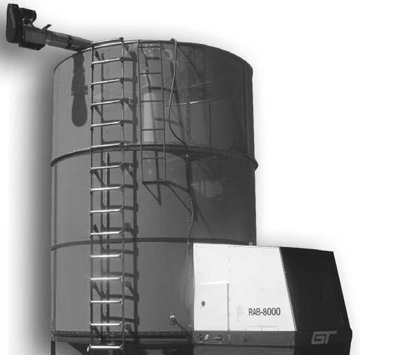
16 1. CONTROLS CONTROLS IDENTIFICATION Do not operate this machine until you have read and fully understand its safe operation. This picture shows all components of the control system of the GT Dryer. All parts are numbered and identifi ed by description. The following pages of the Operation, Maintenace and Service sections refer to the following information contained herein. STUDY THIS INFORMATION. IT WILL GREATLY ASSIST YOU IN THE OPERATION OF YOUR DRYER. Dryer Controls 14 Junction Box Electrical Control Box 1. Pressure Regulator 2. Pressure Gauge 3. Ball Valve 4. Microprocessor 5. Solenoid Valve Coil 6. Flame Detector 7. Air Switch 8. 12V Ignition Coil 9. Quick Acting Valve 10. Propane Inlet 12. Electric Control Box 13. Main Power Disconnect 14. Aux. Loading Outlet 15. Aux. Unloading Outlet 16. Contactor, Fan Motor 17. Contactor, Vertical Auger 18. Contactor, Aux. Loading 19. Contactor, Aux. Unloading 20. Contactor, Loading 21. Contactor, Unloading 22. AC-DC Relay 23. DC Power Supply 24. Circuit Breaker, Main 25. Breaker, Auger 26. Breaker, Fan Motor 27. Breaker, DC Power 28. Breaker, Aux. 29. Breaker, Loading Mtr. 30. Breaker, Unloading Mtr.
17 2. PLENUM HIGH LIMIT CONTROL The high limit control safeguards against excessive plenum temperatures. The maximum temperature is factory set and microprocessor controlled. An additional high limit thermostat is placed in the plenum and acts in conjunction with the microprocessor. During the initial start-up of the dryer the microprocessor checks the high limit thermostat to make certain the plenum temperature falls within the operating range. If so, operation continues and the dryer begins the cycle. Should the thermostat open at any time during operation, power to the controller will be interrupted, halting operation of the entire unit. 3. LOADING THE BIN DANGER The loading auger operates automatically and may start without notice. Make certain that the auger is free of debris and that everyone stays clear of the intake. Failure to do so may result in serious injury or death. The standard loading hopper may be used in conjunction with bin unloading equipment or it may be extended to reach under a hopper bottom bin. An auxiliary outlet is also provided which becomes energized as the dryer begins to load. This outlet can be used to operate an auxiliary electric auger, such as a bin unloader or transport auger, to fi ll the dryer. The grain can also be loaded directly into the top of the dryer. When the loading hopper attachment is used for fi lling the dryer, follow these steps to prevent the grain from being fed into the dryer faster than the vertical auger can recirculate it. When this happens the grai.n can build up in the bottom of the dryer until it gets into the agitator assembly and causes damage to the agitator. A. Make sure that the vertical auger drive belt is kept tight and is not slipping. B. Make sure the discharge holes at the top of the vertical auger housing are completely open with the swivel head in the recirculation position. C. Make sure that the bottom auger well is kept clean of trash or fi ne material build up which restricts the fl ow of grain into the intake of the vertical auger. D. The vertical auger fl ighting cannot be worn down at the intake end. E. When using the folding hopper, set the grain fl ow regulator in the loading hopper down 1½ as shown in the drawing. See Figure A. Figure A Figure B F. Adjust the loading hopper feet so they touch the ground as the loading auger becomes fully engaged with the drive portion of the auger. See Figure B. 15

18 DANGER The loading auger operates automatically and may start without notice. Make certain that the auger is free of debris and that everyone stays clear of the intake. Failure to do so may result in serious injury or death. G. The grain bin will fi ll until the grain is approximately 10 inches below the top ring. Wet grain expands as it is heated. Leaving a couple of inches at the top provides the additional room needed and prevents the dryer from spilling over. DO NOT LEAVE GRAIN IN DRYER OVERNIGHT. Grain that remains in the dryer overnight will absorb moisture and swell. This swelling can cause the vertical auger to cease. When the loading attachment is not used, overhead bins or a conventional farm type elevator or auger may be used. In using any method of fi lling from top, make delivery of grain into dryer as near to center as pos- sible. Start machine, without burner, at the same time loading begins. this helps keep bin loaded evenly. Bin will fi ll to rim and pyramid evenly to auger outlet. OPERATING INSTRUCTIONS Turning the controller on and off is accomplished using the keypad, thus eliminating the protruding toggle switch used on prior models. Basic Controller Operation - The controller operates from a source of nominally 12 Volts DC. This Voltage will be provided by a supply internal to the dryer. That supply derives its power from the same AC source which is used to run the dryer s motors. As soon as DC power is available, a portion of the controller becomes active, even though the unit appears to be completely off. The current drawn while the controller is in this mode is only a few milliamps. The controller may be allowed to remain in this state indefi nitely as the power consumed is insignifi cant. The keypad area on the controller, which is shown in Figure 2B, is where the operator provides the information needed to control dryer operation. Options may be quickly accessed in an intuitively-simple sequence. Figure 2B - Keypad area of the controller The ON and OFF keys have only one function, to apply or remove electrical power to the controller and the dryer s DC circuitry. The remaining keys are used to select options while the dryer is in operation. Controller States - While running, the controller can be in only one of eight possible states. These have been assigned descriptive names which will appear in the display when the controller is in the Status mode. Table 2A list these states. 16
19 The fl ow chart in Figure 2C describes how the controller moves from state to state. When the unit is fi rst set to on, the Idle state will be active. State Numb 0 State Name Idle Description Idle state - no automatic operations are under way 1 Fill Grain bin is being fi lled 2 Purge Plenum is purged of possibly explosive gases 3 Ignite Ignition of burner 4 Heat Fuel heater is being warmed 5 Dry Grain is dried 6 Cool Cooling grain 7 Unload Unload grain in bin Table 2A - The controller, once it is set to on, can only be in one of the 8 possible states listed above. When the controller is set to the status mode, the state name will be shown in the LCD window. If the unit has been off and the ON key is pressed, the Idle state will be active. Figure 2C - Controller state fl ow diagram. The rectangles represent the allowed states while the labels next to the lines are the logical conditions required to cause the transition indicated. The + is a logical OR and multipli- cation is logical AND. Dryer Operating Modes - There are two drying options, a fi lling option, an unloading option and a mode where the dryer motors may be operated manually. While the latter is available primarily for troubleshooting, the other four will routinely be used in the course of drying and handling the grain. The fi lling and unloading options are available to allow the operator to load or unload grain from the dryer bin. 17
20 The two drying options are Automatic Dry and Batch Dry. The latter operates just as a single-batch dryer would, allowing the drying of whatever grain is in the dryer at the time, and stopping after the grain has been dried and unloaded. The Automatic Dry option will fi rst attempt to fi ll the grain bin if it is not currently full. Once fi lled, the controller will move the dryer through the same states as if Batch Dry was in effect until the grain is unloaded. At that point, rather than the controller returning to the Idle state, it will return to Fill. In this mode, the RAB dryer can dry batch after batch without operator intervention. A combination of the two modes is also possible. If the dryer is started in the Batch Dry mode and then, after burner operation commences, it is shifted to Automatic Dry mode, it will complete the drying of an initial batch without fi rst going through a fi ll. Continuous batch operation will then occur after the initial batch has been fi nished. Errors - The controller returns immediately back to the Idle state should an error condition be detected. For example: in the Purge state, the fl ame detector is checked. Since the fuel valves are closed at this time, no burner operation is possible. So, if the fl ame detector module in the dryer indicates that a fl ame is present - probably due to a failed fl ame detector unit - something is wrong. At that point the controller will return to the Idle state with the LCD display showing the message Flame On. The INDICATOR LIGHT will also be lit. Even certain normal or expected conditions may produce such an outcome. In Automatic Dry opera- tion, the grain supply may eventually be exhausted. After a period passes and the dryer determines that it is unable to refi ll the bin, dryer operation will stop, although due to no fault of its own. The message No Fill will be displayed and the INDICATOR LIGHT will be lit. Basic Drying Cycle - The controller will remain in its inactive state until the ON key on the controller keypad area is depressed. Depressing the ON key will cause normal operation to commence. The display will show a message of the form Hours xxxxx where xxxxx is the total number of elapsed hours the controller has been in operation since manufacture. NOTE: This time is NOT the period that DC power has been applied to the controller s electrical terminals, but the time that the controller is actually active. The diagram in Figure 2D illustrates the primary menu options presented to the operator and under what conditions they are presented. It is important to note that this diagram is quite different from the machine state diagram of Figure 2C. The state diagram shown previously indicates how the controller and dryer complete the instructions presented by the operator. The menu option diagram below shows what the controller displays to the operator and how the controller will respond to the choices made. Sub-menus are not shown in Figure 2D (page 19). For example: the box titled SELECT GRAIN ITEMS includes steps to select the grain type, plenum set point, grain set point, whether temperatures should be displayed in degrees F or C, etc. These details are not shown, However, there is only one way into and one way out of these sub-menus. That is what is depicted in the diagram. 18
21 Figure 2D - Menu options provided the operator by the controller. The boxes represent message states. The items next to the lines are the conditions required to make the indiated transition. some boxes contain additional sub-displays not shown here which require operator inputs, but they do not alter the overall fl ow as shown here. The + symbol represents a logical OR and multiplication represents logical AND. IDLE Options - Once the controller has been set to on and the hours message is displayed, only the OFF, STATUS and MENU keys have any effect. OFF Key - The OFF key will turn the controller off and remove DC power from all parts of the dryer which it controls. STATUS Key - When the STATUS key is pressed, if no error conditions are present, the display will cycle between two messages. One of these will be Idle, indicating the current state of the controller. The sec- ond display will be the current grain temperature. No drying functions are being performed, other than monitoring certain dryer conditions, such as its DC Voltage supply level. The status display does not expect any operator inputs and will respond only to the MENU or OFF keys. The status display s purpose is to provide information on the dryer s current operating condition. Except when actual control functions are being performed, the status display should be activated so the controller can provide information on current dryer conditions. MENU Key - Pressing the MENU key, either when the hours display is present or when either status message is present, will activate the controller s menu routine. It is used to set dryer operating parameters, start and stop drying, as well as manually controlling motors. 19
22 Grain Parameter Setting - The fi rst option provided to the operator after the MENU key is depressed will allow him to select the grain to be dried, desired temperatures and whether the temperatures are displayed in degrees C or F. The values previously set for the last load of grain dried are the fi rst presented. This allows a YES response at each option to preserve the previous value. The (UP) and (DOWN) keys may be used to modify numeric values as well as select different grains. Switching between degrees F and degrees C never alters dryer operation and may be done at any time. With the exception of choosing the grain, all grain-related options are also available when drying is in progress. The grain parameter setting process may be skipped by responding with NO whenever the option message Set Drying Data? is present in the display. Drying Options - After passing the grain drying parameter setting routine by answering NO as indicated above, the operator will be asked to make a selection which will start or stop the basic drying process. If the dryer is in the Idle state, the options to commence drying will be provided. If drying has already been initiated, the option to stop drying or to switch to the other drying mode will be provided. Additional Non-drying Options - If the dryer is in the non-drying Idle state, two or three additional options are available in the menu area. These are accessed if the drying options were answered with a NO response. If the dryer grain bin is not full, the Fill On? option will be presented. A YES response will cause the dryer to attempt to fi ll the bin with grain. If this option is chosen, a sensor will terminate the fi lling process when the bin becomes full. If the dryer is unable to fi ll the bin due to a lack of grain after adequate time to do so has passed, it will also stop with the error message No Fill. If the bin is already full, this option will not be presented. If the option to initiate fi lling of the bin was absent, due to the bin already being full, or if it was bypassed by answering NO, the Unload On? option will then be presented. Unlike the fi lling option, even if the grain bin is empty, unload is available to provide a means of cleaning small grain residues from the bottom of the unit. It will run a short time after the empty sensor detects the bin is empty and then stop unloading. The fi nal option is Manual Motors On? A YES response will open a sub-menu which will allow the operator to individually control every motor available on the dryer which the controller can activate or deactivate. In manual mode, the dryer s sensors are not monitored. For example: the fi ll motor can be set to run even if the bin is full. Without operator intervention, it will continue running. The manual motor routine is useful when troubleshooting dryer operation. The last option in the manual motor area is Auto Motors On? A YES returns the controller to the grain setting point and a NO takes the operator back to the start of the manual motor area. If the Fill? or Unload? options or either dry option was activated, the dryer will no longer be in the Idle state. In this event, the Manual Motors On? options will not be available. Leaving the MENU Routine - It is not possible to return to the status routine until any active sub-menus have been completed. These two are the grain parameter setting and manual motor control segments. With this exception, pressing the STATUS key will restore the status display. Loading and Unloading - The dryer may be loaded or unloaded without the activation of a drying cycle. Once fi lling or unloading has begun, the STATUS key will return the unit to the status display mode, which is similar to the Idle display, except the word Idle is replaced by either Fill or Unload, depending on the choice previously made. In the Fill state, the menu option will allow setting the automatic drying mode by responding with a YES to Auto Dry On?. This will cause the dryer to continue fi lling, but then move on to automatic drying when the bin is full. 20
23 Drying - There are two types of drying cycles: batch and automatic. Presuming there are no failures such as loss of electrical power, exhaustion of burner fuel or mechanical problems in the dryer, the batch mode dries the current load of grain, cools the grain if desired, and then unload the bin, stopping in the Idle state. When it stops, the message Grain Done is present. In the automatic mode, the grain bin is fi rst loaded and then the grain is dried. A cool-down state may or may not occur next, depending on cool-down temperature settings. The bin is then unloaded, followed by the dryer returning to the Fill state to start a new cycle. This will continue until terminated by the operator or some problem occurs, including a lack of enough grain to fi ll the bin. In the case of this latter event, the dryer will return to the Idle state with an appropriate message on the LCD display. If the display is set to the status mode, the progression through the various states may be observed by watching the messages on the LCD display. The drying portion of the cycle progresses as follows: a 16-second Purge state is entered fi rst during which any unburned gas in the plenum is expelled by the dryer fan. It at the start of this period that the fan will be activated. After the purging time has passed, the controller will move to the Ignite state. The electric ignitor will generate a spark and the low-fl ow fuel path will be opened so that fuel is supplied to the burner. This period will continue for up to 90 seconds, if needed, during which time the burner should light. Once ignition occurs, the controller will move to the Heat state. This is a 30 second period during which the high-fl ow fuel path remains blocked. This will assure that dryers that need to heat the fuel for effi cient burn- er operation will have time to raise the temperature of the fuel heater. In the previous three cases, the status display shows only the state of the controller, or Purge, Ignite and Heat, respectively. But once the dryer reaches the drying state, the status display will alternate between the state - Dry - and temperature information for the plenum and the grain. When the grain reaches the preset grain temperature for dryness, the unit will move on to the Cool state where the burner is now extinguished and the grain is cooled by ambient air supplied by the fan. The displayed messages are similar to those in the Dry state, but the plenum temperature is omitted as the burner is extinguished. When the cool setpoint is reached, unloading commences. If the cool setpoint and grain setpoint are equal, the Cool state is terminated immediately after being entered and the dryer moves directly to unload. Manual unloading can also be initiated if the operator wishes to unload in the bin without completing the drying process. The dryer must be removed from the drying mode to do this. Safety and Control Monitoring - A variety of sensors provide information to the controller about the dryer s condition. These check for excessive plenum temperatures, burner fl ame presence or absence, air fl ow through the burner, grain and plenum temperatures, the magnitude of the 12 Volt DC internal supply, grain bin being full or empty. Some conditions are monitored continuously, while others are only checked when to do so is vital for safe dryer operation. Whenever an unsafe condition is detected, the controller will stop all dryer operation over which it has control, thus returning the dryer to the Idle state. A message indicating the problem which produced the halt is presented. Since some of these conditions may be transient, the problem may vanish by the time the operator returns. To avoid losing the cause, the detected condition is latched on the display. The operator can clear it by pressing any key. Some normal conditions will stop the dryer as if they were failures. For example: if the controller had been set to fi ll the bin, but the automatic batch mode had not been set, when the bin becomes full, the dryer will return to the Idle state and display the message Fill Done, as well as turning the INDICATOR LIGHT on. The OFF button may always be used to instantly remove power from all of the 12 Volt DC devices controlled by the unit, including the burner fuel solenoids and motor contactors. The internal switching device is a relay, thereby assuring that there are no residual currents fl owing in any of the controlled elements. 21
24 Detailed Controller Operation Assumptions - In this section it is assumed that the controller and the associated dryer are in good working condition. The exception will be certain error conditions that may reasonably be expected to occur, such as failure to fi ll because the grain source has been exhausted. See Section 6 for a discussion of controller operation when failures occur. Controller Options - The controller options which are available to the operator are shown in Figure 4A. Figure 4A - RAB Keypad input options and their effects. Drying Operation - While fi lling the grain bin may be commenced by the operator before drying parameters are set, some of the options available to the operator when the unit is in the Idle state are not available once the Fill state has been activated. The following discussion assumes all options are to be maintained, so fi lling will not be commenced until other drying conditions have been established. Initial Dryer Setup - The following steps will begin grain drying. Turn the Unit On - After the dryer has been completely setup mechanically and electrically, including providing a supply of wet grain and fuel, depress and release the ON key. The display will change from being blank to Hours xxxxx 22 where xxxxx will be a number between 000 and The number displayed will be the number of hours that the controller has been in the operating state.


25 Controller STATUS display - Press the STATUS key. The path to reach the Status display is shown in Figure 4B. Figure 4AB - Path from Hours display to Status display Providing that no error conditions exist, the display will switch to one of the two messages shown below. Idle or Grain ttt sddds That message will remain for 2 seconds and then change to the other, which will then be present for an equal period of time. When both message have been shown once, the display will cycle back to the fi rst message and repeat. Idle informs the operator of the state of the controller and dryer i.e. no action in regard to drying is under way The Grain portion of the second message informs the user that the numbers to the right are related to the temperature of the grain in the dryer bin. ttt is the temperature of the grain. sddd is the temperature difference between the grain setpoint and the current grain temperature. s is the sign of the difference and will be + to indicate that the grain in the bin is above the setpoint and - to indicate that it is below. S is the temperature system and will be F for Fahrenheit and C for Celsius. 23

26 Figure 4AC - The MENU key will activate the drying conditions option. 24 Establishing Drying Conditions - Press and release the MENU key. The path taken by the controller to reach the grain parameter setting display is shown in Figure 4C. Providing that no error conditions exist, the display will switch to the messages shown below. Set Drying Data? When the dryer is in the Idle state, the Menu routine has fi ve areas. These are: 1. Grain parameter setting 2. Activating/deactivating drying 3. Filling the grain bin 4. Emptying the grain bin 5. Motor control The Set Drying Data? message is asking the operator if he would like to enter the grain parameter setting sub-menu. If it is desired to set or adjust the grain parameters, press YES. If the current settings are known to be acceptable, press NO. If the latter choice is made, the controller will move to the drying options. Select Grain - Press and release the YES key. The display will now change to: Gggggggg? where Gggggggg? represents one of the grains in the controller s library. The selected grain from the library will always be the one selected when the dryer was last used. So, if the grain selected for drying during the previous use was corn, the controller will initially display Corn? This recall of the previously set parameters is true for all of the settings in this sub-menu. This allows the operator to turn the unit off and return later to dry another batch without having to remember the previous settings. The appearance of a? in any controller message is a prompt for the user, reminding him that he is expected to make a selection.
27 If the grain displayed is not the one desired, use the (UP) and (DOWN) keys to step through the alphabetized table until the desired grain is reached. NOTE: once either of these keys is used, even if the same grain as dried last time is eventually selected, all previously set grain parameters will be replaced by those values stored in the controller s library. In other words, those previously set will be lost. A change in the selected grain can only be made when the unit is in the Idle state. The only way the controller can exit the grain selection sub-menu is to press YES. Select Temperature System - Once the desired grain is displayed, press YES. The display will change to: Degrees S? S will either be C or F, indicating that the current temperature displaying system is Celsius (C) or Fahrenheit (F). A NO response will switch the display to the other system while another NO will return it to the original. This sub-menu may only be left by answering with a YES key depression and the last displayed system will be the one set. Set the Plenum Temperature - Depressing and releasing the YES key will cause the display to change to: Plenum? ttt sddds The Plenum portion of the message indicates that the current plenum temperature setpoint conditions are being displayed. The?, as with all controller displays, shows that the value may be adjusted. The ttt sddds format is very similar to the one previously introduced. ttt is the desired or setpoint plenum temperature during drying, rather than the actual temperature. sddd is the sign and difference, but in this case, the difference is between ttt and the suggested value found in the controller s library. This allows the operator to see how far the suggested set point has been changed from the library value. S, as before, is the temperature system. It will be F for Fahrenheit and C for Celsius. If the plenum set point displayed is not the one desired, the (UP) and (DOWN) keys may be used to step the values until the desired point is reached. One depression will raise or lower - depending on which key is used - the set point one degree. If either key is depressed and held, the temperatures will increment or decrement at the rate of once per second until the key is released or a limiting value is reached. The library contains limiting values, above which the plenum may not be set. Attempting to lower the plenum temperature below the grain setpoint is not allowed either. If the grain type was unchanged, then the initial plenum setpoint will be whatever it was set to previously. If the grain selection was changed, the initial value will be the one stored in the library. Changing the plenum setpoint has no effect on any other setting. It may be changed before drying commences or after it has begun. This sub-menu may only be left by answering with a YES response, establishing the last displayed value as the setpoint. Select the Grain Temperature - Pressing the YES key will cause the display to change to: Grain? ttt sddds The Grain portion of the message indicates that the current grain temperature setpoint conditions are being displayed. The? shows that the value may be adjusted. The ttt sddds format is very similar to the one described for the plenum. ttt is the desired (maximum) grain temperature during drying, rather than the actual temperature. sddd is the sign and the difference between ttt and the suggested value in the controller s library for the selected grain. This latter value allows the operator to see how far the set point has been changed from the suggested setting in the library. S is the temperature system and will be an F for Fahrenheit or a C for Celsius. If the grain setpoint displayed is not the one desired, use the (UP) and (DOWN) keys until the 25
28 desired value is reached. One depression will raise or lower - depending on which key is used - the setpoint one degree. If either key is depressed and held, the temperatures will increment or decrement at the rate of once per second until the key is released or a limiting value is reached. The library also contains values above which the grain may not be set. Attempting to raise the grain temperature above the plenum setpoint is also not allowed. The grain temperature may not be set to freezing or below. If the grain type was unchanged, then the initial grain setpoint will be whatever it was set to previously. If the grain selection was changed, the initial value will be the one stored in the library. Changing the grain setpoint has no effect on any other setting. It may be changed before drying commences or after it has begun. This sub-menu may only be left by answering with a YES response, establishing the last displayed value as the setpoint. Select the Cool-Down Temperature - Pressing the YES key will cause the display to change to: Cool? ttt sddds The Cool? portion of the message indicates that the user can adjust the temperature the grain must reach before unloading will commence. The ttt sddds format is similar to the two previously introduced. ttt is the grain temperature which will initiate an unload. sddd is the sign and the difference between ttt and the grain setpoint temperature. S is the temperature system and will be an F for Fahrenheit and a C for Celsius. NOTE: Care must be exercised in setting the cool temperature. If it is set above the grain temperature setpoint, unloading will never occur. This will also happen if the cool down temperature is set below the ambient temperature. If the grain setpoint displayed is not the one desired, use the (UP) and (DOWN keys until the desired value is reached. One depression will raise or lower - depending on which key is used - the setpoint one degree. If either key is depressed and held, the temperatures will increment or decrement at the rate of once per second until the key is released. If the grain type was unchanged, then the initial cool setpoint will be whatever it was set to previously. If the grain selection was changed, the initial value will be the one stored in the library. Changing the cool setpoint has no effect on any other setting. It may be changed before drying commences or after it has begun. After the cool temperature has been set, the YES key must be depressed and released. This will cause the controller to return to the state it was in before the grain drying parameter subprogram was entered at the beginning. The display will once again shows Set Drying Data?. Depress and release the NO key to move to the dry- ing mode options. If it is desired to return to the grain parameter setting sub-menu, perhaps to change a previously accepted value, press the YES key. Drying Mode Options - Once the grain drying parameters are set, the operator is provided with several options to initiate the drying process. Figure 4D (page 27) shows the options which are available. Four Initial Choices - Although Figure 4D shows three apparent options, the fi rst contains two closely associated choices, making a total of four. These appear in the following order: automatic continuous batch dry- ing, single batch drying, grain bin fi ll and grain bin unload. 26
29 Figure 4D - A NO response to Set Drying Data? will provide the unshaded options. Automatic Continuous Batch and Single Batch Drying - When the dry option mode is entered by answering NO to Set Drying Data? Presuming the dryer has not been previously set to initiate drying, the dis- play will present the message: Auto Dry On? This will be the option most frequently chosen. A depression of the YES key will start the sequence of events which will lead to continuous drying of batches of grain. The basic steps will be to fi ll the bin, purge the heating chamber, ignite the fl ame, warm the fuel preheater, dry the grain, cool the grain, unload the dry grain and then repeat. If the grain bin is already full, it will skip the fi rst step on the fi rst pass through the cycle. It will continue in this fashion until the grain bin cannot be fi lled, a failure occurs, or the operator intervenes to stop the dryer. A NO response to the Auto Dry On? message will produce the following display: Batch Dry On? This option will allow the drying of a single batch of grain. It does not fi ll the grain chamber at the start and stops after any grain in the bin has been unloaded. In all other regards, it operates like the automatic continuous batch mode. 27
30 28 Fill and Unload Options - If both drying options are rejected by a NO response, then one of the following two messages will be displayed: Fill On? Unload On? If the bin is not currently full, then Fill On? will be shown. If the bin is full, then the fi lling option will be bypassed and the unloading option presented immediately. If the Fill option is displayed, a YES response will initiate the fi lling of the drying chamber with grain. A NO response will cause the controller to present the unloading option. A YES to the Unload On? message will initiate immediate unloading of the grain bin. While a YES response to either option will immediately return the display to the Set Drying Data? message, the selected action will continue until completed or stopped. Both fi lling and unloading have a time-out mechanism, stopping the dryer motors if the requested process does not complete in the time allotted. The time out limit is 40 minutes. In the unloading mode, operation continues for 1 minute after the internal bin sensors indicate that the bin is empty. This is done to empty the grain from the grain handling system. Options when not in Idle - If the dryer is not in the Idle state, the options shown in Figure 4D are changed. Batch or Automatic Dry in effect - If either continuous or single batch drying was previously initiated, the fi rst option provided will be Dry Off? As might be expected, a YES will terminate the drying process. A NO will bring up the next option. If the response was a NO, the drying option not in effect will be offered i.e. batch dry will be suggested if automatic dry is in effect; automatic will be suggested if batch is operational. A YES will change the drying mode to the newly-suggested one while a NO will return the user to the grain-setting question. NOTE: if either drying mode is cancelled while the bin is being fi lled or unloaded, the controller will revert to Fill and Unload respectively. Filling or Unloading Active - If fi lling has begun, the option to stop fi lling will be provided, but the option to unload will not. If unloading has begun, the option to stop is provided, but the option to fi ll is not. In both cases, the option to commence an automatic batch drying cycles will be provided. This would allow the operator to begin or continue fi lling or unloading the bin and automatically initiate the drying cycle later. During filling, the batch dry mode will also be available. Additional Choices - If the dryer is in the Idle state and NO is the response to Unload On?, the display will change to: Manual Motor On? This is an option provided for manually operating the dryer s motors and most likely would be used for troubleshooting purposes. The normal response is NO, returning the user to the grain data setting mode. Running Operation - As Figures 4C and 4D indicate, in almost every state, the STATUS key may be depressed to return the controller to the status displaying mode. Any options which were being presented when STATUS was pressed are cancelled. It will be necessary to select MENU to once again access the operation setting modes of the controller. Pressing the STATUS key never alters what the dryer is doing, but only changes what the controller displays. Fill Status Display - Providing that no error conditions exist, when the dryer is in the fi lling state, the display will cycle between the two messages shown below. Each will remain for 2 seconds and then switch to the other for an equal period of time. When both message have been shown once, the displays will repeat. Fill or Grain ttt sddds
31 Fill shows the state of the controller and dryer i.e. the controller is attempting to fi ll the dryer s bin with grain. The grain message is the same one as shown in the Idle state, with ttt being the actual grain temperature and sddd being the sign and the difference between the grain temperature and the grain setpoint temperature. S is the temperature system; F for Fahrenheit and C for Celsius. A + sign means the grain is above the setpoint and A - means it is below. Purge Status Display - Providing that no error conditions exist, the display will be as shown below: Purge Purge is the state of the controller and dryer i.e. the burner chamber is being fl ushed of possibly explosive gasses. This stage lasts for 16 seconds before the dryer moves on to Ignite. The grain stirring mechanism and the fan are all operating by the end of this state. Ignite Status Display - Providing that no error conditions exist, the display will be as shown below: Ignite Ignite is the state of the controller and dryer i.e. the controller is attempting to ignite the burner fl ame. This lasts a maximum of 90 seconds, but will normally be terminated earlier when the burner ignites and the fl ame detector determines that the burner is operating. Heat Status Display - Providing that no error conditions exist, the display will be as shown below: Heat Heat is the state of the controller and dryer i.e. the burner is operating in the low-output mode to heat the fuel preheater. This lasts for 30 seconds. The drying state will follow. Dry Status Display - Providing that no error conditions exist, the display will cycle between the messages shown below. Each will remain for 2 seconds and then switch to the next for an equal period of time. When all message have been shown once, the cycle of displays will repeat. Dry or Plenum ttt sddds or Grain ttt sddds Dry is the state of the controller and dryer i.e. the dryer is drying the bin grain. The Plenum message indicates that the data to the right is the temperature information about the hot air chamber. ttt is the temperature of the plenum air. sddd is the sign and temperature difference between the cur- rent plenum temperature and the plenum set point temperature. s will be + to indicate the plenum is above the setpoint and - to indicate that it is below. S is the temperature system and will be F for Fahrenheit and C for Celsius. The Grain message indicates that the data to the right is the temperature information for the bin grain. ttt is the temperature of the grain. sddd is the sign and temperature difference between the temperature and the grain setpoint temperature. s will be + to indicate that the grain in the bin is above the setpoint and - to indicate that it is below. S is the temperature system and will be F for Fahrenheit and C for Celsius. Cool Status Display - Providing that no error conditions exist, the display will cycle between the two messages shown below. Each will remain for 2 seconds and then switch to the other for an equal period of time. When both message have been shown once, the display will repeat. Cool or Grain ttt sddds Cool is the state of the controller and dryer i.e. the dryer is cooling the now-dry grain in the bin. The Grain message indicates that the data to the right is temperature information about the bin grain. ttt is the temperature of the grain. sddd is the sign and temperature difference between the grain temperature and 29
32 the grain cool-down setpoint. s will be + to indicate that the grain in the bin is above the setpoint and - to indicate that it is below. S is the temperature system and will be F for Fahrenheit and C for Celsius. Unload Status Display - Providing that no error conditions exist, the display will cycle between the two messages shown below. Each will remain for 2 seconds and then switch to the other for an equal period of time. When both message have been shown once, the display will repeat. Unload or Grain ttt sddds Unload is the state of the controller and dryer i.e. the dry grain is being unloaded from the dryer. The Grain message indicates that the data to the right is temperatures information about the bin grain. ttt is the temperature of the grain. sddd is the sign and temperature difference between the grain dry setpoint and the current grain temperature. s will be + to indicate that the grain in the bin is above the setpoint and - to indicate that it is below. S is the temperature system and will be F for Fahrenheit and C for Celsius. End of Drying - Dryer operation is halted in one of three ways: 1. A problem is detected. 2. The batch mode was set and the grain has been unloaded. 3. Manually by the operator. In all three cases, the gas valves are closed, the ignition is, and the motors are halted. The dryer is in the Idle state. In the event of either of the fi rst two, the display will have a message indicating what condition stopped dryer operation. Unload Done is the display for the normal completion of drying in batch mode. All others are considered abnormal conclusions to the drying process. With one exception, the indicator lamp on the front panel will be lit whenever a stop occurs by any means other than operator intervention. That one condition is over-voltage, as the high Voltage could burn out the lamp. In the event of either a case 1 or 2 stop, the indicator lamp may be extinguished and the normal Idle sta- tus display restored by pressing any front panel key except OFF, which would turn the controller off. Manual shut down should normally be implemented by using the MENU key to reach the operatoradjustable options. The grain setting option is fi rst rejected. If either of the drying modes was in effect, the display will present Dry Off? The proper answer is YES. If the dryer was fi lling or unloading, rejecting the drying options will present the option to stop the fi ll or unload activity. Again, a YES will halt the machine, restoring the Idle state. Emergency Shutdown - The OFF key may be used to instantly halt all controller activity. However, this should not be routinely used to terminate dryer operation as it increases the wear on the controller s internal relay. Manual Motor Operation - There are times when it may be useful to operate the dryer motors manually. This option is provided only when the dryer is in the Idle state. The state of the dryer can be determined from the Status display. Once in Idle, the manual motor routines may be accessed. NOTE: No error conditions are checked while in the manual motor routine. The operator is required to monitor all operations. Reaching the Manual Motor Routines - Figure 4E indicates how the Manual Motor routine may be reached. This path may be followed only if the controller is fi rst placed in the Idle state. 1. Whether the controller is in the elapsed hours or status mode, the MENU key should be pressed. 2. To the message Set Drying Data?, press NO. 30
33 3. To both the Auto Dry On? and Batch Dry On? messages, press NO. 4. If the Fill? message is presented, press NO. 5. To the Unload? Message, press NO. 6. To the Manual Motors On? message, press YES. Figure 4E - Path for activating manual motor control. Manual Motor Control - All manual motor options operate in the same fashion. First a message is presented. If it is accepted by answering YES, the current state of the motor will be unchanged i.e. if it was stopped, it will remain stopped; if it was running, it will remain running. For example: Fill Off? This is the fi rst option presented when the manual motor mode is fi rst reached. Responding with a YES will leave the motor in the off state and the controller will go to the next motor with a similar question. If the response is a NO, the display will change to: Fill On? Responding with a YES would now turn the motor on while a NO will return to the previous Fill Off? option. When the presented state is the desired one, press YES. If the opposite state is the desired one, the proper response is NO. A NO response always causes the controller to provide the opposite option. 31
34 Regardless of the state of the motor, running or stopped, the options for each motor can only be left with a YES response - affi rming the motor s current operating state. Options are provided for the motors in the following order: 1. Fill 2. Unload 3. Fan 4. Circulate Leaving Manual Motor Control - After leaving the circulate motor option, the following message will appear Auto Motors On? A NO response will return the user to the start of the manual motor control option list at the fi ll motor option. A YES key depression will return the dryer to the Set Drying Data?. When the manual motor routine is exited, all motors are set to the stopped state. NOTE: The large motors used in the dryer draw high currents during starting. To prevent damage to the motors or excessive tripping of their protective circuit breakers, they should not be started more than once every ten minutes. Controller Initialization & Error Codes - Before a controller can be used on a dryer, it is necessary to set the controller type to RAB. Since it is reasonable to set the elapsed time at this same time, access to the clock initialization routine is also provided. Whenever the dryer controller stops because of an error, the conditions present when the stop took place are saved in the controller s EEPROM. These may prove to be helpful when troubleshooting an elusive problem. How to access to the EEPROM codes is provided here as well. Activating Initialization Routine - Figure 5A (page 33) indicates the path the controller will follow to reach the fi rst initialization subroutine. Power Up - The controller must be connected to an appropriate power source. This may be the dryer power supply or any source of 12 VDC capable of delivering 100 ma or more. Press the ON key. The display will indicate: Hours xxxxx Where xxxxx will usually be a number between 000 and In rare instances, if the controller has never been initialized before, unusual characters may be displayed in the xxxxx area. NOTE: if the MENU or STATUS keys are pressed before the following procedure is completed, the unit cannot be initialized except by turning the power off and then starting again. That procedure will return the user to the point where the initialization routine may once again be activated. Entering the Initialization Routine - Press the YES, NO, (UP) and (DOWN) keys all at the same time. (These four keys do not have to be pressed at the same instant, but must at some point all be depressed simultaneously.) Setting the Controller Type - The display will change to one of the following three messages: Single Batch or Cont. Batch or Cont. Flow 32

 shows the path followed by the controller to reach the hour setting location. The display will become: Hours xdhtu where xdhtu is the current elapsed time.")
35 Figure 5A - Path to the initialization routines. Pressing the NO key repeatedly will cause the message to change to the next option below, or, in the case of the last one, back to the top option. Press NO if needed to bring up the message Cont. Batch. When that message is displayed, press YES. Setting the Elapsed Hours - This subprogram will allow the displayed elapsed time of operation to be manually set. Figure 5B (page 34) shows the path followed by the controller to reach the hour setting location. The display will become: Hours xdhtu where xdhtu is the current elapsed time. u, t, h, d, and x are the units, tens, hundreds, thousands and ten-thousands digits, respectively. Units and Tens Setting - When the routine is entered, the (UP) and (DOWN) keys may be used to set the t and u digits in the display. Both digits, taken together, may be changed one unit at a time between 00 and 99. While both the tens and units may be adjusted in this way, a YES response after u has been set to the desired value will cause further inputs to only change the t digit. Consequently, the smallest amount of time required to set the clock is to use the (UP) and (DOWN) keys to set the u or units digit, and then press YES and use the same keys to set the t or tens digit. Whichever method is used, two YES entries will be required to reach the h setting point. 33
36 34 Figure 5B - Entry path to Clock setting and EEPROM reading routines. If any displayed character is not one of the common numerals 0-9, use either the (UP) and (DOWN) key repeatedly until both digits are in the 0-9 span. The digits may then be set in the usual way. Setting xdh Digits - A similar procedure will allow the xdh digits to be set. However, the x digit may never be selected by itself, but must be set with the d digit. The time display has partial leading-zero blanking, so when the value is less than 10000, there will only be four digits shown. Numbers less than 1000 contain only three digits. Since the display cannot be set higher than 25599, any attempt to surpass 255 for the top three characters will cause the display to roll over to 0. Completing Hours setting and EEPROM Code Reading - Figure 5B indicates two ways that the clock initialization routine may be exited. If, after setting the clocks thousands and ten thousands digits, the YES key is pressed once again, the initialization routine is terminated immediately. But if the NO key is fi rst depressed and held, followed by the YES key while still holding the NO key down, when the YES key is then released, the EEPROM codes may be read as. The NO key may then be released. EEPROM Codes - The EEPROM codes may be reached as described above in the clock set routine or by a more direct route if the clock and controller type is not to be changed. In the latter instance, after turning the controller off and then turning it on by pressing and releasing the ON key, press the YES, NO, (UP) and
37 (DOWN) keys all at the same time. (These four keys do not have to be pressed at the same instant, but must at some point all be depressed simultaneously.) Once the initialization routine has been activated, press and release the YES key four times. Then depress and hold the NO key. While still holding the NO key down, press and release the YES key. The NO key can then be released. Data Display Format - The display will look like the one shown below: nn dd where nn is a two digit hexadecimal number and corresponds to the location of the data being displayed. dd is the hexadecimal data stored in that location. Moving through the Data - Every time the YES key is pressed and then released, the location nn is incremented. The data is not stored in contiguous locations. Location 08 is followed by location 50; after location 5F will come location C0. CF is the last location. The next YES depression will return the controller to the Hours xxxxx display. Failures and Exceptional Condition Processing Failsafe Operation - The circuitry of the controller and the associated dryer have been designed so single failures will not cause unsafe conditions to develop. For example: should the controller fail with the fuel valves open and the burner operating, the plenum temperature would eventually reach the point where the plenum temperature limit switch would open. This would open the fuel valve electrical supply, shutting off the fuel supply to the burner. This is not to say that problems cannot occur which might result in loss. If, for example, the operator attempts to dry a load to a very low moisture content or to dry the grain very quickly, a fi re can be started in the grain bin. Unless the operator takes appropriate steps to extinguish the fi re, grain destruction and damage to the dryer could occur. Monitored Variables - Table 6A lists the various items monitored by the controller. Item DC Supply Voltage level Grain Bin Full Grain Bin Empty Agitator Rotation Auger Rotation Plenum Over-Temp Switch Plenum Temperature Air Flow Flame Detector Grain Temperature Table 6A Sensor inputs utilized by the controller. What Constitutes a Failures and the Controller s Response - Page 22 describes how to operate the controller, assuming that the dryer-controller combination functions in the intended manner. But if the controller detects some undesired or exceptional condition, it will generally take four actions. These are: 1. Lit Indicator Lamp - The front-panel INDICATOR LIGHT will be lit. 35
38 2. Return to Idle - The controller returns to the Idle state if it is not in that state. This will involve halting all dryer motors, closing all fuel valves and stopping the ignitor. 3. Failure Message - The Display will provide information that will allow the operator to determine the failure or condition which caused the dryer to halt. Error Code Recording - The controller contains a memory device whose contents are preserved even when the power is removed. Whenever a special condition is detected, the controller records all of the machine data available in this memory device. When a failure occurs, the general goal is to return the unit to a safe condition so that no destruction may result from the failure and to draw the operator s attention to the failure. But some expected conditions have the same goal. When a single batch of grain is fi nished drying, it would be appropriate to halt all dryer operations and alert the operator. Due to the similarity in actions required of the controller in cases such as these, the controller treats both of these situations the same i.e. as if they were failures. Table 6B lists all possible error messages and their meanings. Message Priority Meaning Voltage Low 7 The 12 Volt DC supply is lower than about 9.5 Volts Voltage High 7 The 12 Volt DC supply is higher than about 17 Volts Plenum Hot 6 Plenum switch or sensor found a high plenum temperature Air Low 6 Air fl ow switch is open, indicating inadequate air fl ow No Flame 5 Flame is absent when it should be present Flame On 5 Flame switch is closed when it should be open No Fill 4 Grain bin did not fi ll within allotted 30 minutes Fill Done 4 Requested bin fi ll was completed normally No Unload 3 Grain bin did not empty within allotted 30 minutes Unload Done 3 Requested bin unload was completed normally Agitator Slow 2 Agitator rotational rate is too low Auger Slow 2 Auger stopped Grain Done 1 Grain drying completed Table 6B Error messages the controller can deliver and their meaning. In some cases it might be possible for two or more failures to occur at the same time. For example: if the motor which drives the auger and agitator would fail to start, both auger and agitator failures would occur. In the event of simultaneous failure conditions, only one is displayed and that will be the one with the higher priority as indicated in Table 6B. 36
39


40
41 PROPANE GAS FLOW CHART 39
42 40 SENSOR LOCATIONS


43 JUNCTION BOX WIRING DIAGRAM - RAB - 12VDC CONTROL BOX 41
44 TERMINAL BLOCK KEY RAB 1. Flame Detector (N.O.) - Black 22 High Limit Switch - White/Black 2. Low Heat Solenoid - Black 23. Relay Panel #1 - Green 3. High Heat Solenoid - Black 24. Full Switch - Brown 4. Agitator Sensor - White/Blue 25. Empty Switch - Brown 5. Plenum Tem. Sensor - White/Orange 26. Fuse - 7 AMP 6. Grain Temp. Sensor - White/Orange VDC Positive - Yellow 7. Plenum Temp. Sensor - White/Black VDC Negative - Brown 8. Grain Temp. sensor - White/Black 29. Auger Sensor - Yellow 9. Auger Sensor - Brown 30. Full Sensor - Blue 10. Full Sensor - Black 31. Earth Ground - Green 11. Empty Sensor - Black 32. Empty Sensor - Blue 12. Liquid Solenoid - Black 33. Agitator Sensor - White/Black 13. Liquid Solenoid - Black 34. High Limit Switch - Orange 14. Relay Panel #6 - Red (Auger Control) 35. Air Switch (N.O.) - Black 15. Relay Panel #5 - White (Fan Control) 36. Open Terminal 16. Relay Panel #4 - Brown (Load Control) 37. Liquid Solenoid - Blue 17. Relay Panel #3 - Yellow (Unload Control) 38. Liquid Solenoid - Blue 18. Ignition Coil (Neg.) - White 39. Fuse - 7 AMP 19. Low Heat Solenoid - Blue 40. Flame Detector (Common) - White 20. High Heat Solenoid - Blue 41. Ignition Coil (Pos.) - Black 21. Air Switch (Common) - White MICROPROCESSOR CABLE BK - Black (Ground) BL - Blue (Liq. Sol.) BN - Brown (Ignition) GN - Green (Agitator) GY - Gray (Common) GY/BN - Gray/Brown (Common) O - Orange (Low Sol.) R - Red (12 VDC Power) BLK/R - Black/Red (Sol. Com.) R/GN - Red/Green (Empty) R/Y - Red/Yellow (Air/High Lim.) T - Tan (Full) V - Violet (Auger) W - White (Flame) W/BK - white/black (Plenum) W/BL - White/Blue (Load Motor) W/BN - White/Brown (Auger Motor) W/GN - White/Green (Unload Mtr.) W/O - White/Orange (Plenum) W/GY - White/Gray (Com.) W/V - White/Violet (Fan Motor) W/Y - White/Yellow (Grain Temp.) Y - Yellow (High Heat Sol.) 42
45 43
")
46 page 12. (See page 11) page 41, 44
47 page 12. page
48 46
49 47
50 48
51 See page 36 49
52 See wiring diagram on page If the high limit switch opens, the display will show PLENUM and operation will stop. 50
53 GRAIN USED FOR PLENUM TEMP. GRAIN TEMP. DRYING TIME COOLING TIME 51
54 POWER FRAME ASSEMBLY THREE PHASE 52
55 POWER FRAME ASSEMBLY THREE PHASE REF. NO. PART NO. NO. REQ D DESCRIPTION 1 D Frame, Power 2 D Brace, Power Frame (US) 1 Sheave, 2B 9.4 PD (US) Lg Plenum (UK) 1 Sheave, 2B 8.0 PD (UK) 1 Sheave, 2B 8.6 PD Lg. Plenum Hub, 2.0 SK Housing, In Line Fan 6 D Venturi, In Line Fan 7 D Fan 8 D Shaft, 1L 2 11 D Support, Large Top Panel 12 D Support, Small Top Panel 13 D Brace, Top Panel Bearing, 2 Pillow Block 33 D Support, Wrapper 35 D Support, Lwr. Panel Left 36 D Support, Lwr. Panel Right Motor, 15 H.P. 220/440 3o TEFC Sheave, 2B 9.4 PD (UK) 1 Sheave, 2B 9.4 PD (UK) 1 Sheave, 2B 11.0 PD, Lg Plenum Hub, SK (UK) 1 Hub, 42 mm SK 46 D Brace, Junction Box 48 D Hitch D52464 (UK) 1 Hitch 60 D Spacer, 2 x 2 x 3/ Key, ½ x½ x 3-7/8 69 D Jacks D Adjustable Jacks (optional) Key, ½ x ½ x 2¼ Pulley, Idler 73 D Spacer 75 D Belt, 2RB D Belt, 2RB Eyebolt, ½ x ½ 96 D Link, Idler 97 D Arm, Idler 100 D Guide, Belt 155 D Brace, Panel 156 D Bracket, Rt. Fan Guard 158 D Bracket, LH Fan Guard 53
56 POWER FRAME ASSEMBLY THREE PHASE 54
57 POWER FRAME ASSEMBLY THREE PHASE REF. NO. PART NO. NO. REQ D DESCRIPTION 1 2 D57435 D Panel, Upper Rear Right Door, Right Upper 3 D Panel, Lower Rear Right 4 D Wrapper, Right Power Frame LP D Wrapper, Right Power Frame NG 5 D Panel, Right Lower Rear 6 D Filler, Bottom, Electric Box 7 D Filler, Top Electric Box 8 D Panel, Lower Right Front 9 D Wrapper, Front 10 D Grill, Front Fan 11 D Panel, Right Fan Guard 12 D Panel, Top Fan Guard 13 D Panel, Left Fan Guard 14 D Wrapper, Left Power Frame 15 D Filler, Door 16 D Door, Left 17 D Panel, Left Lower Front 18 D Panel, Lower Front Decal, Grease Line Eyebolt, 1/2 x 1 1/ Decal, GT Logo Decal, Electrocution Decal, Be a Safe Operator Decal, Caution Proper Grounding Decal, Auxiliary Unload Decal, Auxiliary Load Decal, On-Off Decal, Danger Electrocution Decal, Danger LP Gas Supply 30 D Mount, Front Micro Box 31 DA Grain Guard Dryer Controller 32 D Mount, Rear Micro Box Knob, Mounting Decal, Valve Decal, RAB Decal, RAB Decal, RAB
58 BURNER SSEMBLY THREE PHASE 56
59 BURNER ASSEMBLY THREE PHASE REF. NO. PART NO. NO. REQ D DESCRIPTION 1 2 D57210 D Tube, Burner (Propane) Burner, Ring (Propane) 3 D52520* 1 Ring, Flame Defl ector 4 D Spark Plug * 1 Vaproizer, Ring Bracket, Vaporizer Bolt, Burner Mt. 8 D Window, Plexiglass 9 D Tube, Outside Liquid to Vapor 10 D Tube, Outside Vapor to Plumb * 1 Tube, Inside Vapor * 1 Tube, Inside Liquid 13 D52374* 1 Tube, Inside Vapor to Burner 15 D Orifi ce - LP 16 D32301* 1 Holder, Orifi ce * 7 Adapter, ½ P. to ½ T. Union * 4 Capscrew, 5/16 x 1¼ Hex 21 D Coupler, Union Brkt * 4 Screw, No. 14 x ¾ Metal Grommet, 3/8 I.D. Rubber Adapter, Fan Screw, No. 8 x ¼ Metal * 1 Nut, Conduit 28 D Tube, Outside, Vapor to Burner Tee, ½ x ½ x ½ N.P.T * 1 Nipple, ½ x Reducer, ½ x ¼ * 1 Plug, ¼ N.P.T Mount, Spark Plug 35 D Bracket, Flame Detector Bulb Mount * 1 Nipple, ½ x 4½ XH Elbow, ½ x 90 0 St. 51 D Shield, Burner (Propane) 52 D Cover, Hole Adapter, 90 0 NOTE: *Propane Burners Only 57
60 PROPANE CONTROL CABINET ASSEMBLY THREE PHASE 58
61 PROPANE 12VDC CONTROL CABINET & PLUMBING ASSEMBLY REF. NO. PART NO. NO. REQ D DESCRIPTION 1 2 D Gauge, Pressure Valve, Solenoid Valve Kit, Diaphram Valve Kit, Direct Valve 3/16 Seat 3 D Regulator, ½ Pressure Valve, Ball 6 D Bracket, Front plumbing 7 D Bracket, Rear plumbing 8 D Clamp, ½ Saddle V-Bolt Nipple, ½ x 6 Sch Connector, ½ T to ½ Pipe 12 D Orifi ce, Nipple, ½ x Nipple, ½ x D Coil, Solenoid Elbow, ½ Sch Elbow, ½ Street Connector, ¼ Tee to ¼ Pipe Elbow, ¼ x 90 Deg Nipple, ½ x D Line, Pressure Gauge Elbow, 90 deg. Brass 32 D Bracket, Plumging Elbow, 3/16 T to 1/8 Pipe 90 Deg. 34 D Line, Air Switch 35 D Box, 3o Junction 36 D Door, Junction Box Decal, J Box Wiring Diagram Decal, Terminal Block 39 D Detector, Flame Connector, 3/8 x 90 Deg Per ft. Conduit, 3/8 Liquidtite Connector, 3/8 Straight 44 D Tube, Air Switch Nut, 1 NF Hex 46 K Air Switch Coil Screw, x ½ Machine Body, 3/8 NPT Solenoid Valve 50 D Coil, Solenoid Valve 12 VDC 59
62 PROPANE 12VDC CONTROL CABINET & PLUMBING ASSEMBLY REF. NO. PART NO. NO. REQ D DESCRIPTION 60
63 MICROPROCESSOR BOX ASSEMBLY REF. NO. PART NO. NO. REQ D DESCRIPTION 1 DA Grain Guard 2 D Mount, Rear Box Knob, Adjusting Cable Lamp Lens 13 D Mount, Front Box 62 SOLENOID VALVE ASSEMBLY REF. NO. PART NO. DESCRIPTION Kit, 3/8 Solenoid Valve Diaphram Repair Kit, ½ Solenoid Valve Diaphram Repair 62 D25542 Coil, 12 Volt Solenoid Valve, 27 Leads w/forks 60 61
64 FRAME ASSEMBLY THREE PHASE 62
65 FRAME ASSEMBLY THREE PHASE REF. NO. PART NO. NO. REQ D DESCRIPTION 1 D Main Welded Frame Less Hitch 2 D Jack D Adjustable Jack (Optional) 3 D Axle Assembly Inner Bearing 5 D Outer Bearing 6 D Nut 7 D Hub with Bearing Cups 8 D Tire, Tube & Rim (Mounted) 9 D Bin Bottom Sheet (Perf, Coated 10 D Bin Bottom Sheet w/access Hole (Perf, Coated) 11 D Access Door Frame 12 D Access Door 13 D Bin Bottom Well w/boot 14 D21161H 1 Bottom Auger Bearing 15 D Spider, RAB 15 D Spider, RAB KD 15 D Spider, RAB Lg. Plenum KD 16 D Grain Sampler 17 D Seal 18 D Cap Lug Bolt Carriage Bolt, ½ x 1½ ¼ - 20 x ½ Slotted HD Machine Screw ½ x 1¼ Capscrew ¼ - 20 x 3/8 Slotted HD Machine Screw /8 x 1¼ Capscrew /32 x 1¼ Cotter Pin Per ft. Grease Line 28 D Grease Line Bracket /8 x 90 0 Elbow /8 Compression Fittings /8 Grease Zerk Pin Clip ¾ Washer /8 x 1½ Capscrew ¼ 0 20 x ¾ Slotted Head Machine Screw 44 D Bracket, Conduit Seal, 2 I.D. Neoprene Shaft Seal, 2.72 I.D. Neoprene Bearing 48 D Bin Bottom Sheet (Solid) 51 D Track Washer, High Lock 53 D Bar, Safety Decal 63
66 AGITATOR ASSEMBLY THREE PHASE 64

67 AGITATOR ASSEMBLY THREE PHASE REF. NO. PART NO. NO. REQ D DESCRIPTION A Bearing, Agitator Roller D Bearing, Paddle Wheel Bronze Busing, 3/
68 66 AGITATOR DRIVE ASSEMBLY THREE PHASE
69 AGITATOR DRIVE ASSEMBLY THREE PHASE REF. NO. PART NO. NO. REQ D DESCRIPTION 67
70 68 PLENUM ASSEMBLY THREE PHASE
71 500 BUSHEL PLENUM ASSEMBLY THREE PHASE REF. NO. PART NO. NO. REQ D DESCRIPTION 1 D Plenum Frame Angle 2 D Connecting Tube 3 D Lid Sheet 4 D Side Sheet Plenum 5 D Cone Cap 6 D Saddle 7 D Front Enclosure 8 D Lower Frame Band 9 D Center Band, 1/8 Thick 10 D Transition Band 11 D Top Ring 12 D Lid Frame Angles 13 D Connecting Tube Trim Ring 14 D Side Sheet with Connecting Tube Hole D Side Sheet (Narrow Strip) 15 D Thermometer Support Bracket 16 D Skirt 17 D Skirt with Slot 18 D Splices, Plenum Skirt 19 D Extension, Saddle No. 14 x 3/4 Self Tapping Screw 21 D Side Sheet with Cleaner Hole 22 D Plate, Cover 25 D Push on Clip ¼ - 20 x 1/2 Slotted HD Machine Screw ¼ - 20 x 3/4 Slotted HD Machine Screw ¼ - 20 x 3/8 Slotted HD Machine Screw #14 x 1/2 Self Tapping Screw /4 x 3/4 Capscrew /16 x 3/4 Self Tapping Hex Hd Screw 33 D Stiffener, Front Sheet Right 34 D Stiffener, Front Sheet Left Sensor, Temperature Plenum Sensor, High Limit Switch Kit Switch D Bracket /4 x 3/4 Washer Nut, Hex # Nut, 3/8 NPT Brass Lock Screw, x 1/2 69
72 600 AND 800 BUSHEL PLENUM ASSEMBLY THREE PHASE 70
73 600 AND 800 BUSHEL PLENUM ASSEMBLY THREE PHASE REF. NO. PART NO. NO. REQ D DESCRIPTION 1 D Plenum Frame Angle D Plenum Frame Angle (800 - Bushel model) 2 D Connecting Tube 3 D Lid Sheet 4 D Side Sheet, Plenum 5 D Cone Cap 6 7 D53061 D Saddle Front Enclosure (600 Bushel Model) 8 D Front Enclosure (800 Bushel Model) D Lower Frame Band 9 10 D Transition Band 11 D Top Ring 12 D Lid Frame Angles 13 D Connecting Tube Trim Ring 14 D Sheet w/connecting Tube Hole, Std Perf D83092 D Lower Frame Band (800 Bushel Model) Center Band, 1/8 thick D Sheet w/connecting Tube Hole, Fine Perf D Side Sheet (Narrow Strip) D Plenum Side Sheet-Narrow 15 D Thermometer Support Bracket 16 D Skirt 17 D Skirt with Slot 18 D Splices, Plenum Skirt 19 D Extension, Saddle No. 14 x ¾ Self Tapping Screw 21 D Side Sheet w/cleaner Hole 22 D Plate, Cover 25 D Push on Clip ¼ - 20 x ½ Slotted Head Machine Screw ¼ - 20 x ¾ Slotted Head Machine Screw ¼ - 20 x 3/8 Slotted Head Machine Screw #14 x 1/2 Self Tapping Screw ¼ x¾ Capscrew D /16 x ¾ Self-tapping Hex Head Screw Stiffener, Front Sheet, Left 35 D Stiffener, Front Sheet Left (800 Bushel Model) D Stiffener, Front Sheet, Right Sensor, Temperatur Plenum High Limit, Sensor D Bracket Sensor Nut, Brass Sensor Spacer, Sensor Washer Spacer, Lid Angle 38 D Clamp, Brace (4 on Solid Extension Dryers) (800 Bushel Model) 39 D Plenum Center Tube Brace Angle (800 Only) 40 D Plenum Center Tube Brace (800 Only) 41 D Plenum Angle Brace (800 Only) 42 D Skirt Reinforcing Band (800 Only) 71
74 AUGER ASSEMBLY THREE PHASE TUBE AND FLIGHT EXTENSION 600 & 800 BU. DRYERS
75 AUGER ASSEMBLY THREE PHASE REF. NO. PART NO. NO. REQ D DESCRIPTION 1 D Head, Horz. Unloading 2 D Flight, Vert. Horz. Head 2 D Flight, Vert. Horz. Head Lg. Plenum D Bushel Model 3 D Flight, Horz. Head Ext. 6 D Clamp, Support (at Spider) 7 D Tube, Horz. Unload Ext. 8 D Guide, Conduit 9 D Support, Horz. Unload Conduit 10 D Lower Stub Shaft Pair Retainer Bearing 12 D Auger Tube (Bottom) Bushel model 12 D Auger Tube (Bottom) Bushel model D Bushel Model Bearing 14 D Flight (Bottom) 14 D Flight (Bottom) & 600 Bushel Model D Bushel Model 15 D Stub Connecting Shaft 16 D Inspection Hole Cover (4 on 600 & 800 Bushel Model) Stub, Tail ½ x 1½ Carriage Bolt /8 x 2 Capscrew 20 D Stub, Upper D Bushel model only Key, ½ x ½ x 1½ 23 D Cleaning Attachment Band Half Band Band, Rear Motor Support Stub, Head Plate, Head Guard, Belt Washer 30 D Grain Cleaner Hole Cover /8 x 1½ Capscrew DA26000 Head Baffl e Assy. (Includes Items 1, 9, 25, 26 & 27) 32 D Clamp, Brace Sheave, 2B Hub, 1¼ SK Pulley, 2B 3 x 7/ Pulley, 2B 3 x 24mm (UK) 35 D Belt, B Rod, Motor Mounting Strap, Motor Mount w/nuts Strap, Motor Mount Angle, Rear Motor Support Snap Ring Motor, 2 H.P Per ft. Conduit, 3/8 x Connector, 3/8 Elbow 45 D Bearing, 2 Flanged Key Key, Woodruff 48 D Half Band Clamp 49 D Half Band Clamp w/mounting Per Ft. Conduit, 3/ Connector, 3/8 53 D Enclosure w/lid Nut, 1¼ /cibdyut Adapter, 1¼ PVC Sensor, Adjustable Wet Grain (Includes 54 & 55) 57 D Spreader, Grain 58 D Adapter, Spout D26326 D Spout, Top Unloaded Head Housing, Vert. Lg. Plenum 61 D Tube, Auger Extension (600 Bushel Only) D Tube, Auger Extension (800 Bushel Only) 73
76 VERTICAL AUGER DRIVE ASSEMBLY THREE PHASE REF. NO. PART NO. NO. REQ D DESCRIPTION Motor, 15HP 1200 RPM 3 Phase (500 & 600 Models) Motor, 20 HP 1200 RPM 3 Phase (800 Model) 2 D Angle, Top Vertical Motor Mount 3 D Angle, Bottom Vertical Motor Mount 4 D Support, Left Vertical Motor 5 D Support, Right Vertical Motor 6 D Plate, Mounting 7 D Brace, Motor Mount Capscrew, 5/8 x 9 1/ Sheave, 3B 5.4 L/Hub Sheave, 3B 6.0 L/Hub (UK) Hub, 1 7/8 SD 48MM C20HP Hub, 42MM SD (15HP) Sheave, 3B 20 L/Hub Sheave, 3B L/Hub (UK) D Belt, B Capscrew, 3/8 x 4 1/ Hub 2 SF (US) Hub, 2 SK (UK) Capscrew, 1/2 x 1 1/2 74
77 VERTICAL AUGER DRIVE GUARDING ASSEMBLY THREE PHASE REF. NO. PART NO. NO. REQ D DESCRIPTION 1 D Binwell with Boot 2 D Panel, Right Motor Guard 3 D Panel, Left Motor Guard 4 D Guard, Left Motor Drive Assembly 5 D Guard, Right Motor Drive Assembly 6 D Guard, Bottom Belt 7 D Angle, Bottom Left 8 D Angle, Bottom Right 9 D Angle, Left Guard Mount 10 D Angle, Right Guard Mount 11 D Angle, Right Belt Guard Mounting 12 D Angle, Left Belt Guard Mounting 13 D Angle, 45 Deg. Mounting 14 D Flat, Left Guard 15 D Flat, Right Guard 16 D Guard, Bottom Belt End Cap 75
78 76 RAB 5000 OUTSIDE SKIN ASSEMBLY THREE PHASE
79 RAB 5000 OUTSIDE SKIN ASSEMBLY - THREE PHASE GRAIN CAPILIARY ASSEMBLY REF. NO. PART NO. NO. REQ D DESCRIPTION 12 D Bracket, Grain Temp Sensor Sensor, Grain Temperature 29 D Strip, Clamping Clip, Jiffy Screw, #10-24 x 3/4 77
80 RAB 6000 OUTSIDE SKIN AND EXTENSION ASSEMBLY 78
81 RAB 6000 OUTSIDE SKIN AND EXTENSION ASSEMBLY REF. NO. PART NO. NO. REQ D DESCRIPTION 1 D Outisde Sheet Fine Perf. Coated 1 D Outside Sheet Std. Perf. Coated Outside Sheet Fine Perf Outside Sheet St. Perf. 2 D Outside Sheet w/hole, Fine Perf. Coated 2 D Outside Sheet w/hole, Std. Perf. Coated 2 D Outside Sheet w/burner H. Fine Perf. 2 D Outside Sheet w/burner H. Std. Perf. 3 D Outside Sheet 34 Wide, Fine Perf. Coated 3 D Outside Sheet 34 Wide, Std. Perf. Coated Outside Sheet 34 Wide, Fine Perf Outside Sheet, 34 Wide Std. Perf. 4 D Cap Ring 5 D Ring Holder 7 D Brace, Middle Auger Band, Dryer Top 9 D Spout Support, Extended 10 D Sheet, Extension Std. Coated 10 D Sheet, Extension Fine Perf. Coated 10 D Sheet, Extension Std. Perf. 10 D Sheet, Extension Fine Perf. 11 D Sheet, Extension Std. Perf. Coated D Sheet, 34 Extension Fine Perf. Coated 11 D Sheet, 34 Wide Extension Std. Perf. 11 D Sheet, 34 Wide Extension Fine Perf. 12 D Rim Connector 19 D Cover Plate 20 D Liquid Tight Conduit /4 Two Screw Connector 22 D Grain Temperature Capillary Support Bracket - Micro 22 D Grain Temperature Capillary Support Bracker - Non Micro 23 D Outside Sheet w/grain Cleaner Hole, Fine Perf. Coated 23 D Outside Sheet w/grain Cleaner Hole, Std, Perf. Coated 23 D Outside Sheet w/grain Cleaner Hole, Fine Perf. 23 D Outside Sheet w/grain Cleaner Hole Std. Perf. 24 D Base, Brace Large Plenum A Ladder (not shown) 79
82 RAB 8000 OUTSIDE SKIN AND EXTENSION ASSEMBLY 800 BU FIXED EXTENSION REF. NO. PART NO. NO. REQ D DESCRIPTION 1 D SHEET, FP EXT. 1 D SHEET, STD EXT. 1 D SHEET, FP CTD EXT. 1 D SHEET, STD CTD EXT. 2 D SHEET, 34 WIDE FP 2 D SHEET, 34 WIDE STD 2 D SHEET, 34 WIDE FP CTD 2 D SHEET, 34 WIDE STD CTD BAND, OUTSIDE TOP EXT. 4 D CAP RING 5 D RIM CONNECTOR 6 D BRACE CENTER AUGER ELECT. 7 D FLOOR SUPPORT 8 D CLAMP, BRACE 9 D ANGLE, OUTSIDE BRACE 10 D ANGLE, EXTENSION BRACE 80

83 RAB 8000 PLATFORM ASSEMBLY REF. NO. PART NO. NO. REQ D DESCRIPTION 1 D FLOOR, WLDMNT LT 2 D FLOOR, WLDMNT RT 3 D MOUNT, FLOOR SUPPORT 4 D PLATFORM SUPPORT PIPE 5 D TARGET, PLATFORM SUPPORT 6 D PLATFORM SUPPORT TUBE END 7 D J-BOLT, 1/2 X 6 8 D TUBE WINCH CABLE MTG PLATE PLATFORM SPLICE 81
1 and 2 Fan Vision Series Portable Dryers
 1 and 2 Fan Vision Series Portable Dryers Operator s Manual PNEG-1456 Date: 09-29-09 PNEG-1456 2 PNEG-1456 1 and 2 Fan Vision Series Portable Dryers Table of Contents Contents Chapter 1 Safety... 5 Safety
2 & 3 Module DriTek Plus Dryers
 OPERATOR S MANUAL 2 & 3 Module DriTek Plus Dryers Division of ffi Corporation 1004 E. Illinois St. Assumption, IL 62510 PNEG-1540 Date: 09-15-2006 PNEG-1540 CONTENTS INTRODUCTION...4 OPERATING PRECAUTIONS...4
3. Turn on the electrical power supply to the dryer, and move the safety disconnect handle mounted on the dryer s upper power box to on.
 DRYER OPERATION - START-UP INITIAL SETUP PARAMETERS Turn the control power switch to on. When the Boot Screen appears touch the START DRYER button. The computer will run a quick check of the system network
GRAIN DRYER 300 SERIES OPERATOR S MANUAL & PARTS BOOK. Form S Printed in U.S.A.
 300 SERIES GRAIN DRYER OPERATOR S MANUAL & PARTS BOOK Form S-3094-12 Printed in U.S.A. P.O. Box 525 Clay Center, KS 67432, U.S.A. (785) 632-2151 (800) 423-9428 FAX (785) 632-3308 Email: info@gtmfg.com
RECIRCULATING BATCH & AUTOMATIC GRAIN DRYERS
 DRYER CATALOG [785] 632-2151 [800] 423-9428 CLAY CENTER, KANSAS U.S.A. 67432 www.gtmfg.com info@gtmfg.com RECIRCULATING BATCH & AUTOMATIC GRAIN DRYERS [785] 632-2151 [800] 423-9428 CLAY CENTER, KANSAS
Technical Data. Name: ERIKA Automat fully automatic machine to divide and to round dough pieces of the same size
 AUTOMAT MANUAL 1 Technical Data Name: ERIKA Automat fully automatic machine to divide and to round dough pieces of the same size Type Divisions Dough Portions (in ounces) Plate Nos. 3 30 1.0 3.5 #35 4/40A
1 INTRODUCTION TO THE MANUAL
 MAGNA GRAIN DRYERS Models Sttandarrd PTO drri ive Updated May 2011 Page 2 of 34 1 INTRODUCTION TO THE MANUAL 1.1 FOREWORD This manual is provided to give you the necessary operating and maintenance instructions
WSK300 Multifunction Wall Control
 WSK300 Multifunction Installation & Operating Instructions WARNING Hearth & Home Technologies disclaims any responsibility for, and the warranty will be voided by, the following actions: Installation and
Digital Moisture Control Thermostat
 Digital Moisture Control Thermostat Installation and Operation Manual PNEG 1711 Date: 2009 PNEG - 1711 Page 1 of 22 06/30/2009 READ THESE INSTRUCTIONS BEFORE INSTALLATION and OPERATION. SAVE FOR FUTURE
S150 S300 CONSTRUCTION HEATERS. Rev: August 15, 2008 SERVICE AND MAINTENANCE MANUAL No PLEASE RETAIN FOR FUTURE REFERENCE PRODUCTS
 S150 & S300 CONSTRUCTION HEATERS Rev: 2.7.2 August 15, 2008 SERVICE AND MAINTENANCE MANUAL No. 934-6637 PLEASE RETAIN FOR FUTURE REFERENCE PRODUCTS A DIVISION OF HAUL-ALL EQUIPMENT LTD. 4115-18 Avenue
Mini-Rooter Operating Instructions
 Mini-Rooter Operating Instructions For 1-1/4 through 4 lines (30mm 100mm) Your Mini-Rooter is designed to give you years of trouble-free, profitable service. However, no machine is better than its operator.
Corn Flame Energy Corn Stove Model 3000
 Corn Flame Energy Corn Stove Model 3000 Installation and Operation Guide Read thoroughly before starting installation Save this manual for future reference SAFETY NOTICE If this stove is not properly installed,
SERVICE MANUAL FOR 6795B,C,D SERIES PACKAGED AIR CONDITIONERS
 SERVICE MANUAL FOR 6795B,C,D SERIES PACKAGED AIR CONDITIONERS TABLE OF CONTENTS 1. Warnings.................................................................. 2 2. Unit Dimensions And Specifications............................................
INSTALLATION INSTRUCTIONS & HOME OWNERS MANUAL ECO 18 ECO 24 ECO 27 IMPORTANT SAFETY INFORMATION
 INSTALLATION INSTRUCTIONS & HOME OWNERS MANUAL ECO 18 ECO 24 ECO 27 IMPORTANT SAFETY INFORMATION As when installing or using any high voltage electrical appliance, basic safety precautions should always
OPERATING MANUAL MODEL AIR 1500TM AIR DRYER
 OPERATING MANUAL MODEL AIR 500TM AIR DRYER Puregas, LLC 226-A Commerce St. Tel: 800-52-535 Broomfield, Colorado Fax: 303-657-2205 P/N P0255 REV A, 02/9/4 TABLE OF CONTENTS.0 GENERAL... 3 2.0 SPECIFICATIONS...
Service Manual Model 3163
 Service Manual Model 3163 Contents Important Safety Information.......... 1 Specifications.................. 2 General Information.............. 2 Direct Vent Requirements........... 2 Propane System................
Single-Module Portable Dryer
 Single-Module Portable Dryer Models: 1100, 1200, 1200S CFAB-1 FAN, CFAB- 2 FAN, C2100A Installation Guide PNEG-1891 Version 3.1 Date: 09-09-16 PNEG-1891 All information, illustrations, photos, and specifications
Evaluation Report 308
 Printed: March, 1983 Tested at: Humboldt ISSN 0383-344 Evaluation Report 308 A Co-operative Program Between ALBERTA FARM MACHINERY RESEARCH CENTRE PAMI PRAIRIE AGRICULTURAL MACHINERY INSTITUTE GT 380 Grain
Grain Flow. Grain Flow. Efficient Reliable Accurate. Automatic In-Bin Continuous Flow Grain Drying. David Manufacturing Co.
 David Manufacturing Co. Grain Flow MAKING PRODUCTS AS RELIABLE AS THE PEOPLE WHO USE THEM. Efficient Reliable Accurate Automatic In-Bin Continuous Flow Grain Drying Grain Flow DMC s Best: Grain Flow with
OPERATING & SERVICE PARTS MANUAL HDS-215 COMBINATION SHRINK SYSTEM
 OPERATING & SERVICE PARTS MANUAL HDS-215 COMBINATION SHRINK SYSTEM FOR HOT KNIFE AND IMPULSE MACHINES READ ALL INSTRUCTIONS CAREFULLY BEFORE OPERATING EQUIPMENT TABLE OF CONTENTS Electrical Requirements
XPS-ProDry User s Guide Dryer Base
 XPS-ProDry User s Guide XPS-ProDry User s Guide Dryer Base For Use with Inkjet Imaging Systems Manual Part#: M-3120 Revision: August 2005 XPS-ProDry User s Guide Written by Frank Mauri & John Brand Published
Condensing Unit Installation and Operating Instructions
 Bulletin WCU_O&I 01 June 2003 Condensing Unit Installation and Operating Instructions WCU Air Cooled Condensing Unit Table of Contents Section 1. Section 2. Section 3. Section 4. Section 5. Section 6.
Operator: Save these instructions for future use!
 50A66-743 Integrated Furnace Control Operator: Save these instructions for future use! FAILURE TO READ AND FOLLOW ALL INSTRUCTIONS CAREFULLY BEFORE INSTALLING OR OPERATING THIS CONTROL COULD CAUSE PERSONAL
GRAIN DRYER. 800 Bu. Form S Printed in U.S.A. Operators Manual & Parts Book SUPPLEMENT
 R 800 Bu. GRAIN DRYER Operators Manual & Parts Book SUPPLEMENT Form S-3084-14 Printed in U.S.A. R P.O. Box 525 Clay Center, KS 67432, U.S.A. (785) 632-2151 (800) 423-9428 FAX (785) 632-3308 Email: info@gtmfg.com
HOMEADVANTAGE II IMPORTANT SAFETY INFORMATION
 INSTALLATION INSTRUCTIONS & HOME OWNERS MANUAL HOMEADVANTAGE II HA008240 HA011240 HA013240 HA018240 HA024240 HA027240 HA036240 IMPORTANT SAFETY INFORMATION When installing or using any high voltage electrical
MC1 NEWTON GRAIN CLEANER STATIONARY OPERATIONS MANUAL
 MC1 Mid-Continent Industries, Inc. 1801 SE 9 th ST., PO Box, Newton, KS 67114 316-283-9648* 800-279-6812* Fax 316-283-0745 NEWTON GRAIN CLEANER STATIONARY OPERATIONS MANUAL Newton Grain Cleaner Operations
CC197 Guide to In-Storage Drying with Supplemental Heat
 University of Nebraska - Lincoln DigitalCommons@University of Nebraska - Lincoln Historical Materials from University of Nebraska- Lincoln Extension Extension April 2014 CC197 Guide to In-Storage Drying
AXIAL HEATER - CSA INSTALLATION & OPERATINGMANUAL. P/N Rev 0 NATURAL GAS LIQUID PROPANE VAPOR PROPANE
 AXIAL HEATER - CSA INSTALLATION & P/N 782014 Rev 0 NATURAL GAS LIQUID PROPANE VAPOR PROPANE CH18T-NGE CH18T-VPGE CH24T-NGEM CH24T-LPGE / LPGEM CH24T-VPGE CH28T-NGEM CH28T-LPGE / LPGEM CH28T-VPGE OPERATINGMANUAL
CC196 Guide for Batch-Drying in a Bin
 University of Nebraska - Lincoln DigitalCommons@University of Nebraska - Lincoln Historical Materials from University of Nebraska- Lincoln Extension Extension April 2014 CC196 Guide for Batch-Drying in
NEWTON GRAIN CLEANER PORTABLE OPERATIONS MANUAL
 MC1 Mid-Continent Industries, Inc. 1801 SE 9 th ST., PO Box, Newton, KS 67114 316-283-9648* 800-279-6812* Fax 316-283-0745 NEWTON GRAIN CLEANER PORTABLE OPERATIONS MANUAL Newton Grain Cleaner Operations
Volume MATHEWS COMPANY. Legacy Series L1250 /L1350 /L2550 /L2650 /L2700 /L3100 /L3105 /L4145 /L5175. Operations Manual
 Volume 1 MATHEWS COMPANY Legacy Series L1250 /L1350 /L2550 /L2650 /L2700 /L3100 /L3105 /L4145 /L5175 2011 Mathews Company 500 Industrial Avenue Crystal Lake, IL 60012 USA Toll Free Number: (800) 323 7045
American Dish Service
 American Dish Service INSTALLATION INSTRUCTIONS Model JDS12 (T) or (R) Muffler Booster (T) 12kW, 240v, 3-ph, (R) 12kW, 208v, 3-ph Manufactured by Hubbell Electric Heater Company for use on American Dish
WCAD-Series Vended Washers Troubleshooting And Fault Codes
 WCAD-Series Vended Washers Troubleshooting And Fault Codes Part # 8533-066-001 5/11 1 Common Troubleshooting Solutions Symptom Probable Cause Suggested Remedy 2 Machine does not start Machine will not
OPERATING INSTRUCTIONS MANUAL (Please retain for future reference) F-400T DUAL FUEL CONSTRUCTION HEATER
 F-400T DUAL FUEL CONSTRUCTION HEATER") OPERATING INSTRUCTIONS MANUAL (Please retain for future reference) For F-400T DUAL FUEL CONSTRUCTION HEATER CERTIFIED FOR USE IN CANADA AND U.S.A. As per Standard ANSI Z83.7 2000/ CSA 2.14 2000 Gas Fired
OPERATING INSTRUCTIONS MANUAL (Please retain for future reference) For F-400T DUAL FUEL CONSTRUCTION HEATER CERTIFIED FOR USE IN CANADA AND U.S.A. As per Standard ANSI Z83.7 2000/ CSA 2.14 2000 Gas Fired
50M Integrated Single or Two-Stage HSI Integrated Furnace Control Kit INSTALLATION INSTRUCTIONS
 50M56-743 Integrated Single or Two-Stage HSI Integrated Furnace Control Kit INSTALLATION INSTRUCTIONS FAILURE TO READ AND FOLLOW ALL INSTRUCTIONS CAREFULLY BEFORE INSTALLING OR OPERATING THIS CONTROL COULD
INSTALLATION, OPERATION, AND MAINTENANCE MANUAL
 INSTALLATION, OPERATION, AND MAINTENANCE MANUAL TUBE AXIAL FANS BTA, WTA, HTA, DDA The purpose of this manual is to aid in the proper installation and operation of the fans. These instructions are intended
OPERATING INSTRUCTIONS MANUAL (Please retain for future reference) F-1500T DUAL FUEL CONSTRUCTION HEATER
 F-1500T DUAL FUEL CONSTRUCTION HEATER") OPERATING INSTRUCTIONS MANUAL (Please retain for future reference) For F-1500T DUAL FUEL CONSTRUCTION HEATER CERTIFIED FOR USE IN CANADA AND U.S.A. As per Standard ANSI Z83.7 2000/ CSA 2.14 2000 Gas Fired
OPERATING INSTRUCTIONS MANUAL (Please retain for future reference) For F-1500T DUAL FUEL CONSTRUCTION HEATER CERTIFIED FOR USE IN CANADA AND U.S.A. As per Standard ANSI Z83.7 2000/ CSA 2.14 2000 Gas Fired
Portable Dryer Touch Screen Controls
 Portable Dryer Touch Screen Controls and Reference Manual PNEG 1509 PNEG 1509 Date: 1 23 08 Reference Table of Contents TABLE OF CONTENTS DRYER SAFETY & DRYER INFORMATION...4 SPECIAL SETUP SCREENS...5
MODEL B2 INSTALLATION MANUAL
 RELEASE DEVICES GENERAL DESCRIPTION MODEL B2 INSTALLATION MANUAL S/N: The B2 Series Time Delay Release Devices are UL Listed, Canadian Listed, and CSFM Listed for use on rolling doors, single-slide and
B-40/B-41 Modulating Temperature Controller
 INSTALLATION & OPERATING INSTRUCTIONS B-40/B-41 Modulating Temperature Controller For Raytherm Boilers & Water Heaters H2 514-4001 WH2 2100-4001 Catalog No. 5000.70 Effective: 12-21-11 Replaces: NEW P/N
Easy Rooter. Operating Instructions
 Easy Rooter Operating Instructions For 3" through 10" lines (75mm 250mm) Your Easy Rooter is designed to give you years of trouble-free, profitable service. However, no machine is better than its operator.
WHEN TROUBLESHOOTING, PERFORM THE STEPS IN ORDER.
 WHEN, PERFORM THE STEPS IN ORDER. BURNER WON T LIGHT Control System 1. Is the main interlock in auto? The burner will not light if the dryer is in manual mode b. No: Switch the main interlock to auto 2.
FIREFLY II PLUS RELEASE DEVICES INSTALLATION MANUAL
 FIREFLY II PLUS RELEASE DEVICES INSTALLATION MANUAL MADE IN THE U.S.A. U.L. LISTED CANADIAN LISTED CSFM: 7300-1418:100 GENERAL DESCRIPTION SERIAL NUMBER The Cookson Company FIREFLY II PLUS Time Delay Release
Use & Care Manual. Electric Tankless Water Heaters. With Installation Instructions for the Installer AP15447 (10/10)
") Use & Care Manual With Installation Instructions for the Installer Electric Tankless Water Heaters The purpose of this manual is twofold: one, to provide the installer with the basic directions and recommendations
Use & Care Manual With Installation Instructions for the Installer Electric Tankless Water Heaters The purpose of this manual is twofold: one, to provide the installer with the basic directions and recommendations
Tranquility Digital Quick Start Guide
 Tranquility Digital Quick Start Guide 97B0107N01 Residential Packaged and Split DIGITAL Geothermal Heat Pumps With igate and vflow Technology B Step Title Page 1 Thermostat Confi guration 3 Staging 3 Auxiliary
Maintenance 5-1. Good maintenance is essential for cleaning results, and long economical life of the washer.
 Maintenance 5-1 5 Maintenance Purpose This chapter discusses the maintenance of your StingRay Parts Washer. In general, the washer is not maintenance-intensive. A few key items, however, need regular,
TO DO IF YOU SMELL GAS
 User's Information Document 1125B User's Information Manual for Endurance EBP Series Modulating Combination Boiler (natural or propane gas) EDP Series Modulating Hydronic Boiler (natural or propane gas)
Power Washer Maintenance
 Power Washer Maintenance Purpose The maintenance of your MART Power Washer. In general, the washer is not maintenance-intensive. A few key items, however, need regular, scheduled care: Use the information
Panel Fan Series Operators Manual (Galvanized and Polymer)
") Panel Fan Series Operators Manual (Galvanized and Polymer) 52" Belt Drive, Galvanized Panel Fan with Three Wing Blade IMPORTANT: READ AND SAVE THESE INSTRUCTIONS Read all instructions carefully before
Panel Fan Series Operators Manual (Galvanized and Polymer) 52" Belt Drive, Galvanized Panel Fan with Three Wing Blade IMPORTANT: READ AND SAVE THESE INSTRUCTIONS Read all instructions carefully before
INSTALLATION AND OPERATION MANUAL GAS SKILLETS MODELS: GTS-30 GTS-40
 INSTALLATION AND OPERATION MANUAL GAS SKILLETS MODELS: GTS-30 GTS-40 CROWN FOOD SERVICE EQUIPMENT LTD. 70 OAKDALE ROAD, DOWNSVIEW, (TORONTO), ONTARIO, CANADA, M3N 1V9 TELEPHONE: (416) 746-2358, FAX: (416)
WCVD-Series OPL Washers Troubleshooting And Fault Codes. Starting serial number ****** (09/13)
") WCVD-Series OPL Washers Troubleshooting And Fault Codes Starting serial number ****** 8533-074-001 (09/13) Common Troubleshooting Solutions Symptom Probable Cause Suggested Remedy Machine does not start
WCVD-Series OPL Washers Troubleshooting And Fault Codes Starting serial number ****** 8533-074-001 (09/13) Common Troubleshooting Solutions Symptom Probable Cause Suggested Remedy Machine does not start
100T399-SOLA SUPPLEMENT TO INSTALLATION & OPERATION MANUAL INCLUDED WITH WATER HEATER (SERIAL NUMBERS BEGINNING LK AND LATER)
") 100T399-SOLA SUPPLEMENT TO INSTALLATION & OPERATION MANUAL INCLUDED WITH WATER HEATER (SERIAL NUMBERS BEGINNING LK AND LATER) WARNING If the information in these instructions is not followed exactly, a
100T399-SOLA SUPPLEMENT TO INSTALLATION & OPERATION MANUAL INCLUDED WITH WATER HEATER (SERIAL NUMBERS BEGINNING LK AND LATER) WARNING If the information in these instructions is not followed exactly, a
Installation instructions for Plenum-mounted add-on electric heaters MODEL TU. MARCH 2011 version 7
 Installation instructions for Plenum-mounted add-on electric heaters MODEL TU MARCH 2011 version 7 THERMOLEC PLENUM HEATER MODEL TU BEFORE YOU START -GENERAL SAFETY AND INSTALLATION PRECAUTIONS Please
Panel Fan Series Operators Manual (Galvanized and Polymer)
") Panel Fan Series Operators Manual (Galvanized and Polymer) Galvanized Panel Fan with Three Wing Blade IMPORTANT: READ AND SAVE THESE INSTRUCTIONS Read all instructions carefully before attempting to assemble,
Panel Fan Series Operators Manual (Galvanized and Polymer) Galvanized Panel Fan with Three Wing Blade IMPORTANT: READ AND SAVE THESE INSTRUCTIONS Read all instructions carefully before attempting to assemble,
Model Series ELECTRIC WATER SYSTEM PUMP. PumpAgents.com - buy pumps and parts online. Model Series. Automatic Multi-Outlet FEATURES
 PumpAgents.com - Click here for Pricing/Ordering Model 36950-2 Series ELECTRIC WATER SYSTEM PUMP Automatic Multi-Outlet FEATURES Self-Priming Diaphragm Design Allows Dry Running Built-in Discharge Check
OPERATIONS AND MAINTENANCE MANUAL FOR THE 8-TON TURF CART ENVIRONMENTAL CONTROL UNIT (ECU) PART NUMBER
 PART NUMBER") OPERATIONS AND MAINTENANCE MANUAL FOR THE 8-TON TURF CART ENVIRONMENTAL CONTROL UNIT (ECU) PART NUMBER 2001927 Prepared by: 860 Douglas Way PO Box 530 Natural Bridge Station, VA 24579 1 1.0 SCOPE: This
OPERATIONS AND MAINTENANCE MANUAL FOR THE 8-TON TURF CART ENVIRONMENTAL CONTROL UNIT (ECU) PART NUMBER 2001927 Prepared by: 860 Douglas Way PO Box 530 Natural Bridge Station, VA 24579 1 1.0 SCOPE: This
INSTALLATION AND SERVICE MANUAL FOR THE SERIES 1000-P FAN SERIES (PNEUMATIC CONTROL) SERIES 1000-H FAN SERIES (HYDRAULIC CONTROL) GEN 2
 SERIES 1000-H FAN SERIES (HYDRAULIC CONTROL) GEN 2") INSTALLATION AND SERVICE MANUAL FOR THE SERIES 1000-P FAN SERIES (PNEUMATIC CONTROL) SERIES 1000-H FAN SERIES (HYDRAULIC CONTROL) GEN 2 Publication No. 01906 Revision 0 Printed in Canada 1.1 INTRODUCTION
INSTALLATION AND SERVICE MANUAL FOR THE SERIES 1000-P FAN SERIES (PNEUMATIC CONTROL) SERIES 1000-H FAN SERIES (HYDRAULIC CONTROL) GEN 2 Publication No. 01906 Revision 0 Printed in Canada 1.1 INTRODUCTION
INSTALLATION AND SERVICE MANUAL FOR THE TAC1000-P FAN SERIES (PNEUMATIC CONTROL) TAC1000-H FAN SERIES (HYDRAULIC CONTROL)
 TAC1000-H FAN SERIES (HYDRAULIC CONTROL)") INSTALLATION AND SERVICE MANUAL FOR THE TAC1000-P FAN SERIES (PNEUMATIC CONTROL) TAC1000-H FAN SERIES (HYDRAULIC CONTROL) Publication No. 01553 Revision 8 Printed in Canada 1.1 INTRODUCTION This manual
INSTALLATION AND SERVICE MANUAL FOR THE TAC1000-P FAN SERIES (PNEUMATIC CONTROL) TAC1000-H FAN SERIES (HYDRAULIC CONTROL) Publication No. 01553 Revision 8 Printed in Canada 1.1 INTRODUCTION This manual
Model Series Series
 PumpAgents.com - Click here for Pricing/Ordering Model 36800-Series 36900-Series ELECTRIC WATER SYSTEM PUMPS Automatic Multi-Outlet FEATURES Self-Priming Diaphragm Design Allows Dry Running Built-in Discharge
Part 2: Installation Instructions cl
 Contents Page: Part 2: Installation Instructions cl. 381-382 1. Delivery scope............................... 3 2. General and Transportation safety precautions........... 3 3. Stand installation 3.1 Installing
USER S INFORMATION MANUAL
 USER S INFORMATION MANUAL UPFLOW/HORIZONTAL & DOWNFLOW TWO STAGE INDUCED DRAFT GAS FURNACES Recognize this symbol as an indication of Important Safety Information If the information in this manual is not
TECHNICAL MANUAL TRAY DRYER
 TECHNICAL MANUAL FOR TRAY DRYER MODEL TD321-3 TRAYDRYER MODEL: TD 321-3 Table of Contents Part 1 - Technical Information * Introduction * Catalogue Cut-sheet and Installation Drawing * Warranty Part 2
For use with models: PGM304-1, versions M-B PGM365-1, versions M-E, M-F & M-G
 PGM-1 Cooktops For use with models: PGM304-1, versions M-B PGM365-1, versions M-E, M-F & M-G Install ation Instructions Part No. 65476 Rev. B Table of Contents Appliance Safety...1 Important Safety Instructions...2
Operator: Save these instructions for future use!
 WHITE-RODGERS 50A55-286 Integrated Furnace Control INSTALLATION INSTRUCTIONS Operator: Save these instructions for future use FAILURE TO READ AND FOLLOW ALL INSTRUCTIONS CAREFULLY BEFORE INSTALLING OR
Operator: Save these instructions for future use!
 031-01284-000/50A55-241 Integrated Furnace Control INSTALLATION INSTRUCTIONS Operator: Save these instructions for future use! FAILURE TO READ AND FOLLOW ALL INSTRUCTIONS CAREFULLY BEFORE INSTALLING OR
Dryer Controller M720
 User Manual Dryer Controller M720 Hardware version 2.00 Software version 2.00 Manual M720 Dryer controller Page 1 of 60 Document history Preliminary version: - Created in April, 2009 Hardware Version 2.00,
QuadraTouch Pro Software Manual Dryer Control System
 QuadraTouch Pro Software Manual Dryer Control System Software is constantly changing. Make sure you are up to date with Sukup s newest software. New software and manuals are available for download at:
Competitor Series Dryers
 Cost Efficient, Competitively Priced, Completely GSI. Competitor Series Dryers "Your Complete Systems Manufacturer." THE COMPETITIVE EDGE GSI Competitor 100 Series grain dryers offer all the latest technological
INSTALLATION AND OPERATION MANUAL ISM-4081 INTEGRATED SHUTDOWN MODULE
 INSTALLATION AND OPERATION MANUAL ISM-4081 INTEGRATED SHUTDOWN MODULE SYSTEM CONCEPT When not transferring fuel, the pressure in the underground piping system for gasoline distribution may fall due to
Operator: Save these instructions for future use!
 WHITE-RODGERS 50A55-474 & 50A55-571 Integrated Furnace Controls INSTALLATION INSTRUCTIONS Operator: Save these instructions for future use! FAILURE TO READ AND FOLLOW ALL INSTRUCTIONS CAREFULLY BEFORE
User s Information Manual
 48AJ,AK,AW,AY020-060 Single-Package Rooftop Gas Heating Units with COMFORTLINK Controls and Scroll Compressors User s Information Manual NOTE TO INSTALLER This manual should be left with the equipment
User s Manual and Operating Instructions
 User s Manual and Operating Instructions Model Numbers: CL-30P-DDF, CL-20F-DDF, CL-24O-DDF, CL-30-DDF READ AND SAVE THESE INSTRUCTIONS IMPORTANT: Read and understand all of the directions in this manual
Drying Tumblers. Troubleshooting. 120 Pound Capacity 170 Pound Capacity. Refer to Page 5 for Model Numbers. Part No August 2007
 HIGH LOAD READY MEDIUM TEMPERATURE LOW LOW AIR FLOW NON REV REV PUSH TO START 10 5 15 0 50 40 60 0 30 10 20 Drying Tumblers 120 Pound Capacity 170 Pound Capacity Page 5 for Model Numbers Troubleshooting
CBT LW MAINTENANCE GUIDE
 CBT LW MAINTENANCE GUIDE PICTOGRAMS Each Signifier displayed here is specific to this User Manual. Menu Previous Advance Note Tip Example Powder Feeder Mixing Bowl Weigh Scale CBP Tanks Control Panel PSD
CALDWELL HEATER INSTALLATION AND OPERATION MANUAL
 CALDWELL HEATER INSTALLATION AND OPERATION MANUAL THIS MANUAL IS FOR THE INSTALLATION, OPERATION AND MAINTENANCE OF HEATER MODELS #H33-NGE-PE, #H33-LPGE, #H28-NGE-PE, #H28-LPGE, #H28-LT-NGE-PE, #H24-NGE-PE,
CALDWELL HEATER INSTALLATION AND OPERATION MANUAL
 CALDWELL HEATER INSTALLATION AND OPERATION MANUAL THIS MANUAL IS FOR THE INSTALLATION, OPERATION AND MAINTENANCE OF HEATER MODELS #H33-NGE-PE, #H33-LPGE, #H28-NGE-PE, #H28-LPGE, #H28-LT-NGE-PE, #H24-NGE-PE,
BESF Box Ventilator. Installation & Operating Manual USA CAN READ AND SAVE THESE INSTRUCTIONS
 Installation & Operating Manual 3001806 03.02 USA CAN BESF Box Ventilator READ AND SAVE THESE INSTRUCTIONS 1200 Northmeadow Parkway, STE 180 Roswell, GA 30076 (770) 587-3238 (800) 255-2923 Fax (770) 587-4731
Isco 3700ZR Sampler. Manual Set
 Isco 3700ZR Sampler Manual Set Assembly #60-2744-045 Copyright 2001. All rights reserved, Teledyne Isco Revision D, December 14, 2012 This set of manuals supports the Isco 3700ZR Refrigerated Sampler.
Conveyor Washer Operation Manual
 Douglas Machines Corp. Conveyor Washer Operation Manual Douglas Machines Corp. 2101 Calumet Street Clearwater, FL 33765 Ph. (727) 461-3477 Fax (727) 449-0029 Do s and Don ts DO Wear Safety Glasses Wear
TURBO Fiberglass Cone Fan and Grill Fan 48'' Belt Drive. Installation & Operator s Instruction Manual
 TURBO Fiberglass Cone Fan and Grill Fan 48'' Belt Drive Installation & Operator s Instruction Manual July 1998 MV1383B Chore-Time TURBO TM Fan Extended Warranty Chore-Time Equipment warrants new TURBO
Tradesman Tradesman K Norseman Workman Sun Blast Premier Foreman Torches. New
 Tradesman Tradesman K Norseman Workman Sun Blast Premier Foreman Torches New TRADESMAN FORCED AIR LP/NG HEATERS Engineered to deliver reliable, directional heat, L.B. White Tradesman heaters feature a
Tranquility Digital Quick Start Guide
 Tranquility Digital Quick Start Guide 97B0107N01 Residential Packaged and Split DIGITAL Geothermal Heat Pumps With igate and vflow Technology Rev.: January 25, 2016 Step Title Page 1 Thermostat Confi guration
INSTALLATION INSTRUCTIONS FOR 6532 SERIES PACKAGE HEAT PUMP
 INSTALLATION INSTRUCTIONS FOR 6532 SERIES PACKAGE HEAT PUMP RV Products A Division of Airxcel, Inc. P.O. Box 4020 Wichita, KS 67204 1976-360 (1-02) PP TABLE OF CONTENTS 1. Warnings......................................................
OPERATING INSTRUCTIONS MIGHTYLAM 2700 ROLL LAMINATOR
 OPERATING INSTRUCTIONS MIGHTYLAM 2700 ROLL LAMINATOR TABLE OF CONTENTS Safety Messages and Electrical Safeguards...3-4 Introduction... Laminator Features...5 Specifications...5 Intial Set-up...6 Operating
ELECTRIC COOKTOP INSTALLATION INSTRUCTIONS
 INSTALLATION AND SERVICE MUST BE PERFORMED BY A QUALIFIED INSTALLER. IMPORTANT: SAVE FOR LOCAL ELECTRICAL INSPECTOR'S USE. READ AND SAVE THESE INSTRUCTIONS FOR FUTURE REFERENCE. U.S.A. WARNING FOR YOUR
Freightliner Refrigerator Troubleshooting Guide For (TJ18F) (TJ22F) (TJ18FP3)
 (TJ22F) (TJ18FP3)") www.dometic.com Freightliner Refrigerator Troubleshooting Guide For Before initiating troubleshooting, the following equipment is recommended: Multimeter, 20 gauge (min) wires to use as jumpers, and 12Vdc
www.dometic.com Freightliner Refrigerator Troubleshooting Guide For Before initiating troubleshooting, the following equipment is recommended: Multimeter, 20 gauge (min) wires to use as jumpers, and 12Vdc
Installation Instructions Dual Fuel Ranges
 Installation Instructions Dual Fuel Ranges E30DF74EPS E36DF76EPS E48DF76EPS 5995447082 2 Safety IMPORTANT SAFETY INSTRUCTIONS Safety Precautions Do not attempt to install or operate your unit until you
V SERIES HDR GAS RANGES
 SERVICE MANUAL ONE POWERFUL PACKAGE V SERIES HDR GAS RANGES TOPS Open Top Hot Top Griddle Top Work Surface BASES Standard Oven Convection Oven Cabinet Base - NOTICE - This manual is prepared for use by
ENGINE PREHEATER. Operating Instructions and Parts Manual. For Models: H H LT 2-12 MH-300 LT 2-12 MH-310 LT 2-12 MH-200 LT 2-12 MH-210
 ENGINE PREHEATER Operating Instructions and Parts Manual For Models: LT 2-12 MH-300 LT 2-12 MH-310 LT 2-12 MH-200 LT 2-12 MH-210 H-175-300 H-175-200 P.O. Box 577 West Highway 4 LaCrosse, Kansas 67548 800-255-2469
RELEASE DEVICES RELEASE DEVICE-WPS MODELS A/B INSTALLATION MANUAL U.L. LISTED CANADIAN LISTED CSFM: :100 GENERAL DESCRIPTION:
 RELEASE DEVICES MADE IN THE U.S.A. RELEASE DEVICE-WPS MODELS A/B INSTALLATION MANUAL U.L. LISTED CANADIAN LISTED CSFM: 7300-1418:100 GENERAL DESCRIPTION: S/N: The "WPS" World Power Series, Time Delay Release
! WARNING To avoid risk of electrical shock, personal injury or death; disconnect power before servicing, unless testing requires power.
 27 Gas Dryer Technical Information MDG9700A * Due to possibility of personal injury or property damage, always contact an authorized technician for servicing or repair of this unit. Refer to Service Manual
HCS GDC D1 Grain Dryer Control TECHNICAL DESCRIPTION
 Grain Dryer Control Table of Contents 1. This is 2. Manual Mode 3. Auto Mode 4. Restart 5. Connecting the 6. Instrumentation Amplifier HCS-200 7. Mounting the Humidity Sensors HCS 4/3 3 4 5 6 7 9 10 2
HEATING AND VENTILATION
 SECTION 14-102.04 14-102.04/ 1 2007OC19 DESCRIPTION The heating, ventilation and air conditioning (HVAC) system is designed to optimize passenger comfort. The system regulates interior vehicle atmosphere,
Cable Drum Machine. Operation Manual 40 SERIES. Cleans 2" to 4" lines up to 75' N O T F O R R O O T S
 Cable Drum Machine Operation Manual 40 SERIES Cleans 2" to 4" lines up to 75' Used For: Sinks, Showers & Floor Drains N O T F O R R O O T S WARNING - Read All Instructions, When Using Electric Tools, Basic
Installation & Service Instructions for Jackson & Church Flexaire Packaged Furnaces SDF-125 thru SDF-400 Gas Firing
 Installation & Service Instructions for Jackson & Church Flexaire Packaged Furnaces SDF-125 thru SDF-400 Gas Firing Important: To protect the unit and avoid damage to the heat exchanger, the blower speed
PRO SERIES GAS FRYERS OWNER S MANUAL
 PRO SERIES GAS FRYERS OWNER S MANUAL MODELS: PF-1 PRO-FRYER, PF2 DUAL PRO-FRYER REVISED OCTOBER, 2009 *PLEASE RETAIN FOR FUTURE REFERENCE This appliance has been tested according to ANSI Z83.116-2009/CSA1.86-2009.
INSTALLATION INSTRUCTIONS FOR 6636 SERIES PACKAGE AIR CONDITIONER
 INSTALLATION INSTRUCTIONS FOR 6636 SERIES PACKAGE AIR CONDITIONER TABLE OF CONTENTS 1. Warnings...................................................... 3 2. Component Match-Up...........................................
THE "SS90" SERIES RELEASE DEVICES MODEL B2 INSTALLATION MANUAL
 S S S S S S S S 90 OLID TATE ECURITIES, INC SOLID STATE FAIL-SAFE UNIT * PATENT PENDING LISTED U 99Y9 RESET L RELEASING DEVICE SOLID STATE SECURITIES, INC. THE "SS90" SERIES RELEASE DEVICES MADE IN THE
PWASH Gallon Parts Washer Assembly & Operating Instructions
 PWASH20 20 Gallon Parts Washer Assembly & Operating Instructions READ ALL INSTRUCTIONS AND WARNINGS BEFORE USING THIS PRODUCT. SAVE THESE INSTRUCTIONS FOR FUTURE REFERENCE. This manual provides important