XPS-ProDry User s Guide Dryer Base
|
|
|
- Alban Freeman
- 5 years ago
- Views:
Transcription


1 XPS-ProDry User s Guide XPS-ProDry User s Guide Dryer Base For Use with Inkjet Imaging Systems Manual Part#: M-3120 Revision: August 2005
2 XPS-ProDry User s Guide Written by Frank Mauri & John Brand Published by: RENA Systems, Inc 136 Green Tree Road Oaks PA All Rights reserved. No Part of this manual may be used or reproduced in any form or for any means either electronic or mechanical without prior written permission of RENA Systems, Inc. Producing copies of any part of this manual for any purpose other than personal use is a violation of copyright laws. Copyright 2002 First Edition 2002 This manual is provided as is, without warranty of any kind, either express or implied, including but not limited to implied warranties for the manuals quality, performance, merchantability, or fitness for any particular purpose. Neither the provider of this manual nor its dealers, distributors or agents shall be liable to the purchaser or any other person or entity with respect to any liability, loss, or damage caused or alleged to be caused directly or indirectly by use of this manual.
3 Table of Contents 1. General Information Description Features...3 Infrared Drying Assembly...3 Center Vacuum Belt...3 Variable Speed Control Selector...3 Control Panel...3 XPS-ProDry Compatibility Specification...4 Material Handling...4 Physical...4 Electrical...4 Electrical Installation Requirements XPS-ProDry Graphic Operator Instructions Control Panel Functions...8 Main Power Selector Switch...10 Vacuum Power Selector Switch...10 Heater Power Selector Switch...10 XPS-ProDry Start and Stop Pushbuttons...10 Speed Potentiometer Material Guide Adjustments...11 Material Guide Adjustments...11 To Adjust the Rear Exit Wheel Technical Adjustments and Maintenance Vacuum System...13 Overview...13 Maintenance...13 Filter Replacement Graphic XPS-ProDry Drive System...15 Drive Motor Belt Adjustment...15 Drive Motor Belt Replacement...16 Maintenance Mailpiece Transport Belts...18 Tension Adjustment...19 Outer Belt Width Adjustment...19 Belt Replacement...20 Maintenance IR Drying System...21 Overview...21 Safety Precautions...21 Infrared Lamp Replacement...22 Preventive Maintenance...25 Drying Assembly Graphics XPS-ProDry Covers...27 Removal...27 Installation...27 Maintenance General Troubleshooting...28 Electrical...28 Electrical...32 Vacuum Pump...33 XPS-ProDry Drive Motor...33 Mailpiece Transport Belts Replacement Parts...34
4 Chapter 1 General Information 1. General Information 1.1 Description 1.2 Features Infrared Drying Assembly Center Vacuum Belt Variable Speed Control Selector Control Panel XPS-ProDry Compatibility 1.3 Specifications Material Handling Physical Dimensions Electrical Requirements 1.4 Overview Transport Base Graphic 1
5 Chapter 1 General Information 1.1 Description The XPS-ProDry is a mailpiece transportation and drying system consisting of a variable speed vacuum enabled transport mechanism that is operated by means of a centrally located control unit. The XPS-ProDry was designed as a compact, heavy-duty mailpiece transport and drying system engineered to optimize the performance of any Ink-jet imaging system. The XPS-ProDry transport system consists of three high-temperature variable speed transport belts, one vacuum operated center belt and two outer adjustable belts. Operation of the XPS-ProDry is achieved by the use of a front mounted control panel consisting of a series of clearly labeled On/Off selector and On/Off pushbutton switches. The control panel houses On/Off selector switches for Main Power, Vacuum Power, and Heater Power. On/Off pushbutton switches are provided for the dryer base Start and Stop functions. The control panel contains a Speed Control adjustment to aid in optimizing the mailpiece drying quality. The XPS-ProDry has been quality engineered and manufactured to provide years of reliable and trouble free operation. WARNING! The XPS-ProDry s electrical connection should only be performed by a certified electrician. Please see page 5 for additional information. 2
6 Chapter 1 General Information 1.2 Features Infrared Drying Assembly The IR Drying Assembly is a source of high intensity light in the short to medium infrared spectrum. The IR lamp transfers its energy to the stock in the form of heat. The increased temperature causes the ink to set at a faster rate than normal. An intensity control is included to compensate for varying job runs. Center Vacuum Belt The high temperature center vacuum belt, which transports the mailpieces from an inkjet imaging system to the mailpiece drying area has vacuum applied to it to maintain the mailpiece positioning with relation to the dryer. Two additional high temperature outer adjustable belts are provided to allow drying on mailpieces from 3 minimum to 18 maximum widths. Variable Speed Control Selector The transport base belt speed can be adjusted to optimize the drying quality of the mailpieces depending on the stock size and speed of delivery from the inkjet imaging system. This is achieved by adjusting the Speed Control knob as needed. Control Panel The controls required to operate the XPS-ProDry are easily accessible and housed in a front mounted control panel. The control panel is equipped with easily identifiable selector or pushbutton switches for all the XPS-ProDry functions. The control panel also contains the Speed Control selector and the majority of the base control electronics. XPS-ProDry Compatibility The XPS-ProDry can be used in conjunction with any inkjet imaging system. 3
7 Chapter 1 General Information 1.3 Specification Material Handling Minimum 3 x 5 Maximum 18 x 22 Thickness (Standard) Single Sheet to 1.5 Physical Overall Length (Base Only) 43 Overall Height 31 Min. - Height Adjustable Overall Width 26¼ Weight 305 lbs. Crated Weight 474 lbs. Electrical Voltage V.A.C. Single Phase Current 20 Amps* *Recommended 20 AMP Dedicated Outlet. Please see the next page for important installation information. Transport Motor Vacuum Pump IR Drying Assembly Control Panel 1/3 H.P. 90 VDC 3.2 A., 1750 Max. RPM Geared to 875 Max. RPM 1/8 H.P. 115 VAC 2.0 A., 3450 RPM 220 V.A.C. Single phase 20 Amps Watt IR Lamps Main Power Vacuum Power Transport Base Start Transport Base Stop Heater Power Speed Potentiometer 4
8 Chapter 1 General Information Electrical Installation Requirements WARNING! The XPS-ProDry s electrical connection should only be performed by a certified electrician. The XPS-ProDry requires a 220 VAC, four wire, single phase service. A dedicated 20 Amp service is recommended. Please have a certified electrician install and verify the supply type, rating and voltage, before connecting the XPS-ProDry to the outlet. If the XPS-ProDry is connected to an incorrectly configured outlet the equipment will be damaged and or personal injury may result. Please have a certified electrician verify that the installation meets all local electric code requirements. The XPS-ProDry is shipped without a plug on the end of its power cord. Please have a certified electrician install the correct power cord plug for your location. Power Cord Wiring Description: Wire Color Electrical Connection Red HOT Black HOT White Neutral Bare Wire Earth Ground 5
9 Chapter 1 General Information 1.4 XPS-ProDry Graphic (Original release pictured above, your machine may vary slightly) 6
10 Chapter 2 Operator Instructions 2. Operator Instructions 2.1 Control Panel Functions On/Off Selector Switches On/Off Pushbuttons Speed Potentiometer 2.2 Material Guide Adjustments Rear Exit Wheel 2.3 Vacuum System Vacuum Pump Overview Maintenance 2.4 XPS-ProDry Drive System Belt Adjustment Belt Replacement Maintenance 2.5 XPS-ProDry Belts Center Vacuum Belt Outer Belts Maintenance 2.6 Drying Lamp Assembly Drying Assembly Overview Safety Precautions Preventive Maintenance Drying Assembly Graphic 2.7 XPS-ProDry Covers Removal Installation Maintenance 2.8 Troubleshooting 2.9 Replacement Parts 7

11 Chapter 2 Operator Instructions 2.1 Control Panel Functions The Transport Base is outfitted with a centrally located control panel which houses all the necessary controls to easily operate the unit. The controls are grouped in three categories of functions: Main Power, Vacuum Power, and Heater Power On/Off Selector Switches Transport base Start and Stop Pushbuttons Transport base Speed Control Potentiometer Main Power Vacuum Power Start Stop Heater Power Speed Control Figure Control Panel Detailing Main Power, Vacuum Power, Start, Stop, Heater Power, and Speed Control (Original revision shown) 8

12 Chapter 2 Operator Instructions Figure 2.1.1a Control Panel (Latest revision shown above) 9
13 Chapter 2 Operator Instructions Main Power Selector Switch The Main Power switch provides power to the Heater Power switch and the dryer base drive system, (Start and Stop pushbuttons). Vacuum Power Selector Switch The Vacuum Power switch provides power to the vacuum pump and initiates vacuum to the dryer base tabletop. When the switch is in the On position the noticeable sound of the vacuum pump s compressor will be heard. The circuit is protected with a field replaceable 5A cartridge fuse. Heater Power Selector Switch The Heater Power switch provides power for the IR drying lamp assembly. When the switch is in the On position power is provided to the drying lamps. The drive system MUST be started (START) before power is available to the Heater Power switch. Power is removed from the Heater Power circuit when the STOP button is depressed. The IR lamp controller is protected by a 20AMP ceramic fuse. XPS-ProDry Start and Stop Pushbuttons The dryer base Start pushbutton powers the dryer base drive motor and initiates the belt movement. When the Start pushbutton is engaged the transport base belts will run continuously. Pressing the Stop pushbutton will immediately stop the dryer base drive motor and movement of the belts. This will also remove power to the IR Drying assembly Speed Potentiometer The Speed Control potentiometer allows adjustment of the dryer base belt speed. A clockwise rotation of the Speed Control dial will increase the belt speed, a counter-clockwise rotation of the Speed Control dial will result in a belt speed decrease. The drive axle RPM range is from 0 875RPM. The circuit is protected with a field replaceable 5AMP Armature fuse. 10


14 Chapter 2 Operator Instructions 2.2 Material Guide Adjustments Material Guide Adjustments Rear Exit Wheel Locking Collar (2) Adjustment Nut Figure Rear Exit Wheel Assembly To Adjust the Rear Exit Wheel The rear exit wheel is used to direct the mailpiece exiting the dryer base. The adjustment will compensate for transferring the mailpiece to additional inline equipment or directed down to a mailpiece collection bin. 1. Loosen the locking collars and center the exit wheel on the center vacuum belt. Tighten the locking collars when complete. 2. Loosen the adjustment wheel to retract or extend the exit wheel on the mounting bracket. Extending the exit wheel to the end of the mounting bracket will direct the mailpiece downward. Retracting the exit wheel to the beginning of the mounting bracket will allow the mailpiece to be transferred to additional inline equipment. 11
15 Chapter 3 Adjustments and Maintenance 3. Technical Adjustments and Maintenance 3.1 Vacuum System Vacuum Pump Overview Maintenance 3.2 Transport Base Drive System Belt Adjustment Belt Replacement Maintenance 3.3 Mailpiece Transport Belts Belt Adjustments Belt Replacement Maintenance 3.4 IR Drying System Overview Safety Precautions Preventive Maintenance 3.5 Transport Base Covers Removal Installation Maintenance 3.6 General Troubleshooting Electrical IR Drying System Vacuum Pump Transport Base Drive Motor Mailpiece Transport Belts 3.7 Replacement Parts These maintenance instructions are provided as is, without warranty of any kind, either express or implied, including but not limited to implied warranties for the instructions quality, performance, merchantability, or fitness for any particular purpose. Neither the producer of this document nor its dealers, distributors or agents shall be liable to the purchaser or any other person or entity with respect to any liability, loss, or damage caused or alleged to be caused directly or indirectly by use of these instructions 12


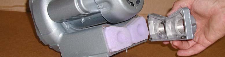
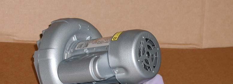
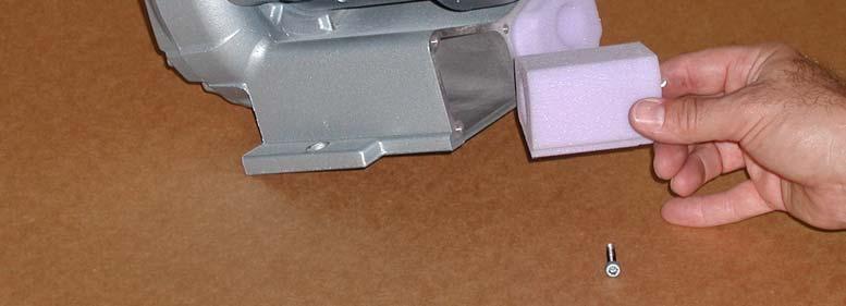
16 3.1 Vacuum System Chapter 3 Adjustments and Maintenance Overview The XPS-ProDry vacuum system consists of a control panel mounted On/Off selector switch, a vacuum pump, distribution piping and a tabletop mounted vacuum manifold. Vacuum Feed Hose Replaceable Filter Location Figure Vacuum Pump and Associated Piping Maintenance The vacuum pump is accessed by removing the front panel. Power must be disconnected before servicing. Be sure all rotating parts have stopped. Electric shock or severe injury can result if the hazard is ignored. Clean intake and exhaust filters as often as needed, blowing down against the current to clean them. Change the cartridges when cleaning no longer gets the cartridges clean. A dirty cartridge causes high intake resistance resulting in an increase of differential pressure, absorbed power and an increase in working temperature. The motor bearings are greased for long life and require no user intervention. Check Vacuum Pump mounting bolts annually and tighten as needed. 13


17 Chapter 3 Adjustments and Maintenance Filter Replacement Graphic Figure Figure

18 Chapter 3 Adjustments and Maintenance 3.2 XPS-ProDry Drive System The XPS-ProDry drive system consists of a Start pushbutton, Stop pushbutton, drive motor, drive pulley, driven pulley and a timing cog belt. Belt Deflection ¾ Timing Belt Adjusting Bolts (4) Pulley Locking Screw Figure XPS-ProDry Drive System Drive Motor Belt Adjustment The drive motor is accessed by removing the front panel. The correct belt deflection has been set up at the factory and under normal use should not require adjustment If timing cog belt does require adjustment: 1. Remove the front cover. 2. Loosen the four (4) drive motor adjusting bolts 3. Adjust the belt deflection measured at the midpoint of the drive and driven pulleys to ¾ 4. Tighten the four (4) drive motor mounts and verify the proper deflection. 5. Repeat steps 1 & 2 if necessary 15
 roller drum shaft end caps. 6.")

19 Chapter 3 Adjustments and Maintenance Drive Motor Belt Replacement 1. Remove the end cover closest to the driven end of the machine. 2. Loosen four (4) drive motor adjusting bolts. 3. Raise drive motor to the top of the mounting bracket and tighten one bolt to hold the drive motor in place. This provides the least amount of belt tension for belt removal and replacement. 4. Loosen the drive motor pulley set screw. 5. Remove the two (2) roller drum shaft end caps. 6. Loosen the two (2) set screws on the roller drum shaft-locking collar. 7. Remove the five (5) rail fastening screw from the tabletop. 8. Remove and set aside the rail-insulating strip. 9. Remove the drive motor pulley from the drive shaft. 10. Tap on the rail to move the roller drum locking collar from the roller drum shaft enough to allow belt removal. 11. Remove belt and replace with new drive belt 12. Place the new belt on the drive motor pulley and replace the pulley on the drive motor shaft, align and install keyway. DO NOT tighten the pulley set screw at this point. 13. Install the roller drum-locking collar on the roller drum shaft. DO NOT tighten the locking collar at this point. 14. Place the rail-insulating strip on top of the rail. 15. Reinstall the five (5) rail mounting screws in the tabletop and loosely tighten 16. Tighten the rail mounting screws starting with the center screws and working outwards. 17. Using a straight edge align the outside flanges of the drive and driven pulley and tighten the locking screws. 18. Loosen the drive motor adjusting bolts and set the correct belt tension. See Section Rail Mounting Screws (5) Roller Drum Shaft Locking Collar Drive Pulley Drive Motor Adjusting Bolts (4) Figure XPS-ProDry Drive Belt Removal 16
20 Chapter 3 Adjustments and Maintenance Maintenance The drive motor is accessed by removing the end panel. The drive motor is a ball or roller bearing motor. The bearings have been lubricated at the factory. The motor does not have any regrease capability and is lubricated for the normal life of the bearings. Check the timing cog belt annually for wear and replace as needed. Check the drive and driven pulley locking screws annually and tighten as needed. Check the drive motor adjusting bolts annually and tighten as needed 17
 high temperature mailpiece")
 3 center vacuum belt and two (2) 1 adjustable outer belts.")

21 3.3 Mailpiece Transport Belts Chapter 3 Adjustments and Maintenance The XPS-ProDry is equipped with three (3) high temperature mailpiece transport belts. One (1) 3 center vacuum belt and two (2) 1 adjustable outer belts. Belt Adjustment Transport Belt Adjustment Screw Transport Belt Roller Shaft Fig Mailpiece Transport Belt Adjusting Screw 1 Belt Play Figure Mailpiece Transport Belt Tension Adjustment 18

22 Belt Adjustment Chapter 3 Adjustments and Maintenance The correct belt tension is measured at the mid point of the tabletop. The center vacuum and two outer belts should have a distance of 1 of play measured from the tabletop to the bottom of the belt surface. See figure NOTE: Do Not Over Tighten the Transport Belts. This Will Lead to Premature Belt Failure Tension Adjustment If the mailpiece transport belts need a tension adjustment: 1. Adjust the transport belt adjustment screw to allow for 1 of belt play measured from the mid point of the tabletop. Turn the belt adjusting screw clockwise to tighten the belt and counter clockwise to loosen the belt. See Figure NOTE: Do Not Over Tighten the Transport Belts. This Will Lead to Premature Belt Failure. Outer Belt Width Adjustment The two 1 outer belts are adjustable to allow for varying mailpiece widths. If the two outer mailpiece belts need width adjustment: 1. Loosen the two (2) locking collar set screws in each of the two outer belt pulleys. 2. Adjust the outer edge of the belts to align with the outer edge of the mailpiece. 3. Tighten the two (2) locking collar set screws in each of the two outer belt pulleys. 4. Turn on the mailpiece transport belts (START) for 15 seconds to auto-align the outer belts on the roller drum shaft. Locking Collar Set Screws (2) Figure Transport Belt Adjustment Graphic 19
 belt adjustment screws to allow the full amount of travel to the transport belt roller shaft assembly. See figure 3.3.1 3. Remove the vacuum feed hose from the barbed brass fitting.")
 and replace as necessary. 9.")
23 Chapter 3 Adjustments and Maintenance Belt Replacement If the mailpiece transport belts require replacement: 1. Remove the front cover 2. Loosen the two (2) belt adjustment screws to allow the full amount of travel to the transport belt roller shaft assembly. See figure Remove the vacuum feed hose from the barbed brass fitting. 4. Unscrew the ¾ x10 black steel vacuum feed pipe from the 90 elbow. 5. Remove the Exit Wheel mounting bar. 6. Remove the six (6) tabletop to dryer base attaching screws. 7. Move the tabletop to the left to allow slack in the drive motor belt, remove the drive motor timing cog belt from the drive pulley. 8. Remove the belt(s) and replace as necessary. 9. Assemble in the reverse order. Move Tabletop to Remove Drive Belt Figure Transport Base Belt Replacement Graphic Maintenance Blow off dirt and debris from belts daily. Remove any ink, as needed using an approved solvent. (i.e. Simple Green) Check belt tension every six months and adjust as needed. Check belts for wear every six months and replace as needed. 20
24 3.4 IR Drying System Overview Chapter 3 Adjustments and Maintenance The IR Drying Assembly is a source of high intensity light in the short to medium infrared spectrum. The IR lamp transfers its energy to the stock in the form of heat. The increased temperature causes the ink to set at a faster rate than normal. The Intensity control provides IR lamp intensities, enabling the operator to compensate for such variables as imaging speed, paper stock, ink coverage, ink color etc. The effectiveness of the infrared drying will vary from job to job based on these variables. Safety Precautions Note the label on the lamp housing. Do not drop flammable liquids on a hot lamp housing. Do not jar or vibrate the IR lamp housing while the IR lamps are still hot. Do not operate the IR lamps unless they are in a horizontal position. When the IR lamps turn off, allow the cooling fans to operate for at least 5 minutes before turning the power switch off. Adjust the height of the IR lamp to maintain a minimum of 2 inches above the stock passing underneath. 21

 connectors for the Heat Lamp Head from the rear panel of the Dryer Base.")
25 Chapter 3 Adjustments and Maintenance Infrared Lamp Replacement CAUTION: Read and follow these instructions carefully. Failure to do so will result in premature failure of the IR lamp, damage to the control box, and create a shock and burn hazard that may result in personal injury. ** Please Note: Use care NOT to touch the replacement bulbs with bare hands. The natural oils from your skin WILL shorten the usable life of the bulbs. Lamp Replacement procedure Unplug the (3) connectors for the Heat Lamp Head from the rear panel of the Dryer Base. Remove the bolts that secure the Dryer Lamp Assembly to the support cross bar and carefully remove the lamp assembly from the base. Support Cross Bar Remove bolts 22

.")

 and gently pull the entire lamp")

 quick connect lamp wires")

26 Chapter 3 Adjustments and Maintenance Set the Lamp head on a clean, flat work surface. Remove the (4) Philips head screws located on both sides of the cooling fans (2 per side). Remove 2 Screws Remove 2 Screws Carefully turn the lamp head over so that the bulbs are facing you. Grab the aluminum lamp housing (to the outside of the ceramic lamp sockets) and gently pull the entire lamp housing from the frame. With the lamp head cords to your right, roll the lamp housing towards you exposing the lamp wiring. Locate and disconnect the (4) quick connect lamp wires by spreading the locking clips outward while pulling the wires away from each other. Carefully guide the disconnected wires through the holes in the lamp housing so that the wires are on the same side of the housing as the bulbs. 23
 end of the lamp housing,")


27 Chapter 3 Adjustments and Maintenance Remove the (4) Philips head screws from (1) end of the lamp housing, releasing the ceramic lamp holders. Remove 4 Screws Remove the U-shaped aluminum lamp holders from the end of the fixture. This will loosen the bulbs and allow them to be slid off the opposite side bulb holders. Replace the bulbs with the new set, again being careful not to expose them to direct contact with your skin. Note: The ceramic insulators must be removed and reused with your new lamps. Reassemble the fixture in the reverse order that is described above. Be careful to make sure that no wires are pinched during this assembly. Place repaired Lamp head back onto the Dryer Base. Plug in the (3) connectors and the Dryer Base should be ready for use. 24

28 Chapter 3 Adjustments and Maintenance Preventive Maintenance Do not allow lubricants or solvents to drip onto the IR lamp housing If any substance (including fingerprints) should come in contact with the glass infrared lamp, carefully wipe the lamp WHEN IT IS COLD, with a lint free cloth and isopropyl alcohol NOTE: Fingerprints on the IR lamp WILL decrease the lamp life. Periodically clean the IR lamp WHEN IT IS COLD, and the parabolic reflector to remove any dust or materials, which may collect over time. Always use a lint free cloth and isopropyl alcohol. NOTE: To increase lamp and drive belt life, on initial setup set the IR intensity adjuster to between 50 and 60% capacity. Drying Assembly Graphics Minimum 2 Clearance Figure Heater Assembly 25

 Figure 3.4.")

29 Chapter 3 Adjustments and Maintenance IR Heater Intensity Adjuster Figure Rear View Showing Intensity Adjuster (Original revision) Figure 3.4.2a Rear View Showing Connectors - Current Revision (Intensity Control Front Panel Mounted) 26
30 Chapter 3 Adjustments and Maintenance 3.5 XPS-ProDry Covers Removal Removal of the cover panels is accomplished by turning the Zeus fasteners one-half turn counter clockwise. Installation Installation of the cover panels is accomplished by turning the Zeus fasteners one-half turn clockwise. Maintenance The front and rear covers are coated with a high quality, durable powder coating. Remove ink, grease and dirt using an approved solvent (i.e. Simple Green) as needed. 27


31 Chapter 2 Troubleshooting 3.6 General Troubleshooting Electrical The Dryer Base Main circuit breaker, Vacuum Pump fuse and Dryer Base drive motor circuit is located in the Dryer Base wiring cabinet. The Dryer Base speed potentiometer control box is also located in the Dryer Base wiring cabinet. The wiring cabinet is accessed by removing the front cover Main Circuit Breaker Heater L1 15A Heater L2 15A Vacuum Pump 5A Base Power 15A Contactor for Heater Control Relay for Heater Cam Switch Field Replaceable Resistor Contactor for Base and Accessories IR Heater Control Box Motor Control Line Fuse 25A Motor Control Armature Fuse 5A Figure Wiring Cabinet Detail (Original Revision) 28


32 Chapter 2 Troubleshooting Figure 3.6.1a Wiring Cabinet Detail (Current Revision) 29


33 Chapter 2 Troubleshooting Relay for Heater Cam Switch Heater Control Fuses 20 A Figure 3.6.1b Internal Dryer Control Wiring Cabinet Detail (Current Revision) 30

34 Chapter 2 Troubleshooting Dryer Control Indicator Lights Dryer Controller PC Board P/N D Figure 3.6.1c Dryer Controller Detail (Current Revision) 31
35 Chapter 2 Troubleshooting Electrical Symptom Troubleshooting Guide Solution No Power to Any Selector or Pushbutton Switch on the Control Panel Verify the Correct Power is Supplied to the Transport Base Check Main Circuit Breaker and Reset as Needed Vacuum Pump Does Not Start Check 5A Vacuum Pump Fuse and Replace as Needed Dryer Base Belts Do Not Move or Drive Motor Does Not Run Verify Speed Control is Not Set to Zero (0) Check 15A Drive Motor Fuse and Replace as Needed Check Motor Control Line and Armature Fuse and Replace as Needed IR Lamps Do Not Turn On Lamps Will Not Power On Unless The Drive Belts Are Moving Check the 20Amp Fuse Located in the IR Control Box and Replace as Needed Check and Replace IR Lamps as Needed Verify proper operation of the drive shaft mounted cam activated Proximity Switch. Red light should flash on Proximity Switch on every rotation of shaft. Verify that the Heater Control relay is operating. Listen for the switching action of the relay as the drive shaft rotates. Check that the signal from the relay is getting to the Heater Control Board by checking the Red and Green Status Lights. Green indicates power is at control board and flashing Red indicates signal from the relay is being received. Ink on the Mailpieces is Not Drying After Passing Under the IR Lamps Increase IR Intensity Switch Until Sufficient Drying Is Achieved Adjust IR Lamps to a Minimum of 2 Inches Above the Stock Reduce Belt Speed 32
36 Chapter 2 Troubleshooting Vacuum Pump Symptom Troubleshooting Guide Solution Vacuum Pump Does Not Start When the Selector Switch is ON Inconsistent or Low Vacuum Condition Check 5A Vacuum Pump Fuse and Replace as Needed Clean or Replace Vacuum Pump Intake and Exhaust Filters as Needed XPS-ProDry Drive Motor Symptom Troubleshooting Guide Solution Dryer Base Belts Do Not Move or Drive Motor Does Not Run Verify Speed Control is Not Set to Zero (0) Check 15A Drive Motor Fuse and Replace as Needed Check Motor Control Line and Armature Fuse and Replace as Needed Mailpiece Transport Belts Symptom Troubleshooting Guide Solution Belts are Moving Too Slowly to Transport Mailpiece Belts Slipping on the Roller Drum Shaft Increase Speed Control Setting Tighten Belts to Recommended Specifications. See Section
37 Replacement Parts 3.7 Replacement Parts DESCRIPTION PART NUMBER 5 AMP Armature Fuse for Speed Control D AC Line Fuse for Speed Control D /3 HP Plug-in Resistor for Speed Control D AMP Fuse for Vacuum Pump Circuit D AMP Fuse for Drive Motor Circuit D0037 IR Heater Assembly D Watt IR Lamp (Two Required) D AMP Ceramic Fuse for IR Lamp Controller D Dryer Lamp Control Board D High Temperature Belt (36 Base) D High Temperature Center Belt (36 Base) D Swivel Casters D0020 Zeus Button (Cover Fasteners) D0079 Zeus Retainer Spring D0016 Drive Motor D0006 Drive Motor Belt D0010 Vacuum Pump D0070 Vacuum Pump Filters D Vacuum Pump Supply Hose D
38 Dryer Base Notes NOTES: 35
TB-390 Conveyor Stacker
 TB-390 Conveyor Stacker OPERATIONS MANUAL Revised: 7-30-14 RENA Systems Inc. would like to Thank You for investing in our quality built products. Please record the following information for future reference:
e Bath Fan with Light User s Guide
 e Bath Fan with Light User s Guide abfl100rnl, BFL125RNL Item Stock Number(s): BFL100RNL, BFL125RNL IMPORTANT INSTRUCTIONS - OPERATING MANUAL READ AND SAVE THESE INSTRUCTIONS READ CAREFULLY BEFORE ATTEMPTING
SHORT WAVE INFRARED PANEL DRYER
 INSTRUCTIONS FOR: SHORT WAVE INFRARED PANEL DRYER MODEL: IR3000 Thank you for purchasing a Sealey product. Manufactured to a high standard this product will, if used according to these instructions and
HEDMAN DI-50. Endorser Instructions. Hedman DI-50 Operators Guide
 HEDMAN DI-50 Endorser Instructions Hedman DI-50 Operators Guide 25-0132-20 TABLE OF CONTENTS 1. INTRODUCTION...1 1.1 DI-50 Description...1 1.2 Items Included...1 1.3 Safety Terms...2 1.4 Safety Precautions...3
WAILEA OWNER S MANUAL
 WAILEA OWNER S MANUAL The blades in each pack are matched for equal weight to assure smooth fan operation. If more than one fan is being installed, be careful not to mix blades from different cartons.
e Heater/Exhaust Fan/Light User s Guide
 e Heater/Exhaust Fan/Light User s Guide abflh70l, BFLH85L Item Stock Number(s): BFLH70L, BFLH85L IMPORTANT INSTRUCTIONS - OPERATING MANUAL READ AND SAVE THESE INSTRUCTIONS READ CAREFULLY BEFORE ATTEMPTING
IMPORTANT INSTRUCTIONS - OPERATING MANUAL
 IMPORTANT INSTRUCTIONS - OPERATING MANUAL Models: AK80LSL, AK100LSL Exhaust Fan READ AND SAVE THESE INSTRUCTIONS READ CAREFULLY BEFORE ATTEMPTING TO ASSEMBLE, INSTALL, OPERATE OR MAINTAIN THE PRODUCT DESCRIBED.
User Manual Box Exhaust Fan Series (Belt Drive)
") User Manual Box Exhaust Fan Series (Belt Drive) 36" Box Exhaust Fan with Three Wing Blade Box with Aluminum Shutter 54" Box with Cone 800-779-3267 sales@schaeferfan.com www.schaeferfan.com 2013 Schaefer
User Manual Box Exhaust Fan Series (Belt Drive) 36" Box Exhaust Fan with Three Wing Blade Box with Aluminum Shutter 54" Box with Cone 800-779-3267 sales@schaeferfan.com www.schaeferfan.com 2013 Schaefer
Shredder FD 8906CC Cross-Cut
 Shredder FD 8906CC Cross-Cut 1/2017 OPERATOR MANUAL Machine Specs Model: FD 8906CC Motor Power Sheet Capacity Serial #: 7.5KW (10HP) Three-phase, 220V, 50/60 Hz, 50 Amp dedicated line required, CS8365
Panel Fan Series Operators Manual (Galvanized and Polymer)
") Panel Fan Series Operators Manual (Galvanized and Polymer) Galvanized Panel Fan with Three Wing Blade IMPORTANT: READ AND SAVE THESE INSTRUCTIONS Read all instructions carefully before attempting to assemble,
Panel Fan Series Operators Manual (Galvanized and Polymer) Galvanized Panel Fan with Three Wing Blade IMPORTANT: READ AND SAVE THESE INSTRUCTIONS Read all instructions carefully before attempting to assemble,
Technical Data. Name: ERIKA Automat fully automatic machine to divide and to round dough pieces of the same size
 AUTOMAT MANUAL 1 Technical Data Name: ERIKA Automat fully automatic machine to divide and to round dough pieces of the same size Type Divisions Dough Portions (in ounces) Plate Nos. 3 30 1.0 3.5 #35 4/40A
READ AND SAVE THESE INSTRUCTIONS READ CAREFULLY BEFORE ATTEMPTING TO ASSEMBLE, INSTALL, OPERATE OR MAINTAIN THE PRODUCT DESCRIBED. PROTECT YOURSELF AN
 READ AND SAVE THESE INSTRUCTIONS READ CAREFULLY BEFORE ATTEMPTING TO ASSEMBLE, INSTALL, OPERATE OR MAINTAIN THE PRODUCT DESCRIBED. PROTECT YOURSELF AND OTHERS BY OBSERVING ALL SAFETY INFORMATION. FAILURE
e Bath Fan with Light User s Guide
 e Bath Fan with Light User s Guide abfl125rok Item Stock Number(s): BFL125ROK IMPORTANT INSTRUCTIONS - OPERATING MANUAL READ AND SAVE THESE INSTRUCTIONS READ CAREFULLY BEFORE ATTEMPTING TO ASSEMBLE, INSTALL,
REV: 000. Mercury Compact Series
 REV: 000 Mercury Compact Series Table of Contents Introduction 2 Standard Operating Guide 2 Features & Specs 2 External Layout 3-8 Internal Layout 9-12 Wiring Diagram 13 F.A.Q. 14-22 Comprehensive Parts
e Bath Fan with Light User s Guide
 e Bath Fan with Light User s Guide abfl50uq, BFL60UQ, BFL70, BFL85 Item Stock Number(s): BFL50UQ, BFL60UQ, BFL70, BFL85 IMPORTANT INSTRUCTIONS - OPERATING MANUAL READ AND SAVE THESE INSTRUCTIONS READ CAREFULLY
ASTRO ENVELOPE FEEDER AMC FOR HEIDELBERG PRINTMASTER INSTALLATION AND OPERATING INSTRUCTIONS
 ASTRO ENVELOPE FEEDER AMC-2000-17 FOR HEIDELBERG PRINTMASTER INSTALLATION AND OPERATING INSTRUCTIONS INTRODUCTION Thank you for purchasing the Astro Envelope Feeder. It is fast, efficient, reliable, and
FD Heavy Duty Feeder for FD 280 Tabbing System
 FD 280-10 Heavy Duty Feeder for FD 280 Tabbing System Operator Manual 8/2011 First Edition TABLE OF CONTENTS 1. INTRODUCTION... 1 1.1 Feeder Description... 1 1.2 Items Included... 1 1.3 Operating Manual
Tempest Hot Air Drying System. Installation Instructions. Sakurai 258II. X / Rev-B
 Tempest Hot Air Drying System Installation Instructions Sakurai 258II X88-57 10/98 2656 Rev-B GENERAL INFORMATION ATTENTION TEMPEST DRYER OWNER! Accel Graphic Systems provides parts and service through
MC-UL Vacuum Cleaner. Specifications are subject to change without notice for further improvement. Order Number MAC CE
 Order Number MAC0708001CE Vacuum Cleaner Specifications are subject to change without notice for further improvement. 2007 PANASONIC CONSUMER ELECTRONICS COMPANY, DIVISION OF MATSUSHITA ELECTRIC CORPORATION
1. SAFETY RULES. 1. To reduce the risk of electric shock, insure electricity has been turned off at the circuit breaker or fuse box before beginning.
 Kichler Basics 403 1 1. SAFETY RULES 1. To reduce the risk of electric shock, insure electricity has been turned off at the circuit breaker or fuse box before beginning. 2. All wiring must be in accordance
INSTALLATION and OPERATION BALL WASHER MODEL NO: BW-022
 Easy Picker Golf Products, Inc. 415 Leonard Blvd. N., Lehigh Acres, FL 33971 PH: 239-368-6600 FAX: 239-369-1579 Service: 800-982-4653 SALES: 800-641-4653 www.easypicker.com salesdept@easypicker.com INSTALLATION
HW-17 Record Cleaning Machine Setup and Instruction Manual
 HW-17 Record Cleaning Machine Setup and Instruction Manual VPI Industries, Inc., 77 Cliffwood Ave. #3B, Cliffwood, NJ 07721 Phone: 732-583-6895, Email: Sales@vpiindustries.com http://www.vpiindustries.com
BEFORE OPERATING THE MACHINE: WARNING
 BEFORE OPERATING THE MACHINE: Read the manual carefully and completely before attempting to operate the unit. This manual has important information for the use and safe operation of the machine. Keep this
OWNER S MANUAL FINLEY FIREPLACE. Product code: UPC code: Date of purchase: / /
 OWNER S MANUAL FINLEY FIREPLACE Product code: 0-08487460-1 UPC code: 817266010267 Date of purchase: / / ELECTRIC FIREPLACE HEATER HOME OWNER'S INSTRUCTION MANUAL Insert Model: SP18-1705-LED ATTENTION FIND
Hatteras BayTM. Patio. Instruction Manual. Includes our new CoolTouch TM Control System Looks permanent, but goes wherever you go! U.S.
 Hatteras BayTM Patio A Kichler Décor ceiling fan Designed to coordinate with a popular Kichler Lighting collection. Includes our new CoolTouch TM Control System Looks permanent, but goes wherever you go!
1. SAFETY RULES WARNING WARNING. 8. Avoid placing objects in the path of the blades.
 1 1. SAFETY RULES 1. To reduce the risk of electric shock, insure electricity has been turned off at the circuit breaker or fuse box before beginning. 2. All wiring must be in accordance with the National
Orrin. Instruction Manual. Includes our new CoolTouch TM Control System Looks permanent, but goes wherever you go! U.S.
 Includes our new CoolTouch TM Control System Looks permanent, but goes wherever you go! U.S. Patent Pending Orrin A Kichler Select ceiling fan Kichler Lighting 7711 East Pleasant Valley Road P.O. Box 318010
TECHNICAL MANUAL TRAY DRYER
 TECHNICAL MANUAL FOR TRAY DRYER MODEL TD321-3 TRAYDRYER MODEL: TD 321-3 Table of Contents Part 1 - Technical Information * Introduction * Catalogue Cut-sheet and Installation Drawing * Warranty Part 2
52 StarkkTM. Instruction Manual. A Kichler Select ceiling fan
 52 StarkkTM A Kichler Select ceiling fan Kichler Lighting 7711 East Pleasant Valley Road P.O. Box 318010 Cleveland, Ohio 44131-8010 Customer Service 866.558.5706 8:30 AM to 5:00 PM EST, Monday - Friday
EAGLE 2000B EAGLE 2000BE EAGLE 2000EBT MUST READ MANUAL PRIOR TO INSTALLING MACHINE
 EAGLE 2000B EAGLE 2000BE EAGLE 2000EBT MUST READ MANUAL PRIOR TO INSTALLING MACHINE Contents 1 Machine Safety Information 3 1.5 Safety Precautions Prior to Operating Machine 6 2 Machine Installation 7
Tempest /PowderPro. Installation Instructions. Heidelberg QM46DI X /98
 Tempest /PowderPro Installation Instructions Heidelberg QM46DI X88-126 8/98 POWDERPRO GENERAL INFORMATION ATTENTION POWDERPRO OWNER! Accel Graphic Systems provides parts and service through its authorized
60" Hatteras BayTM. Patio. Instruction Manual. Includes our new Wall Control System. A Kichler Décor ceiling fan
 Includes our new Wall Control System 60" Hatteras BayTM Patio A Kichler Décor ceiling fan Kichler Lighting 7711 East Pleasant Valley Road P.O. Box 318010 Cleveland, Ohio 44131-8010 Customer Service 866.558.5706
ValkyrieTM. Instruction Manual. Includes our new CoolTouch TM 6 Speed DC Control System Looks permanent, but goes wherever you go! U.S.
 ValkyrieTM A Kichler Décor ceiling fan Designed to coordinate with a popular Kichler Lighting collection. Includes our new CoolTouch TM 6 Speed DC Control System Looks permanent, but goes wherever you
π H-2268 SANITAIRE UPRIGHT VACUUM SAFETY uline.com
 π H-2268 SANITAIRE UPRIGHT VACUUM 1-800-295-5510 uline.com SAFETY PAGE 1 OF 7 NOTE: When using an electrical appliance, basic precautions should always be followed, including the following: READ ALL INSTRUCTIONS
52 Lacey LED. Instruction Manual. 6 Speed DC Wall Control System
 6 Speed DC Wall Control System 52 Lacey LED HIGH EFFICIENCY DC MOTOR Kichler Lighting 7711 East Pleasant Valley Road P.O. Box 318010 Cleveland, Ohio 44131-8010 Customer Service 866.558.5706 8:30 AM to
42 Kevlar. Instruction Manual. Kichler Lighting 7711 East Pleasant Valley Road P.O. Box Cleveland, Ohio
 42 Kevlar Kichler Lighting 7711 East Pleasant Valley Road P.O. Box 318010 Cleveland, Ohio 44131-8010 Customer Service 866.558.5706 8:30 AM to 5:00 PM EST, Monday - Friday Instruction Manual 1 1. SAFETY
Breezex (BX) Heavy Duty Reversible Supply/Exhaust Fans with Reversing Switch. IMPORTANT! Read before proceeding! OPERATION & MAINTENANCE MANUAL
 Heavy Duty Reversible Supply/Exhaust Fans with Reversing Switch. IMPORTANT! Read before proceeding! OPERATION & MAINTENANCE MANUAL") Breezex (BX) Heavy Duty Reversible Supply/Exhaust Fans with Reversing Switch OPERATION & MAINTENANCE MANUAL IMPORTANT! Read before proceeding! Please read and save these instructions. Read carefully before
Breezex (BX) Heavy Duty Reversible Supply/Exhaust Fans with Reversing Switch OPERATION & MAINTENANCE MANUAL IMPORTANT! Read before proceeding! Please read and save these instructions. Read carefully before
Wiring Instructions for the 2900 Series FIREGUARD Combination Door Closer-Holder and Releasing Device with Integral Smoke Detector
 Wiring Instructions for the 900 Series FIREGUARD Combination Door Closer-Holder and Releasing Device with Integral Smoke Detector CAUTION: FAILURE TO INSTALL OR ADJUST PROPERLY MAY RESULT IN INJURY OR
60" Tulle PatioTM. Instruction Manual. A Kichler Select ceiling fan
 60" Tulle PatioTM A Kichler Select ceiling fan cul Certified for Wet Location Kichler Lighting 7711 East Pleasant Valley Road P.O. Box 318010 Cleveland, Ohio 44131-8010 Customer Service 866.558.5706 8:30
54" Skye. Instruction Manual Customer Service :30 AM to 5:00 PM EST, Monday - Friday A Kichler Decor ceiling fan
 54" Skye TM 300167 A Kichler Decor ceiling fan Includes wall mount control system Kichler Lighting 7711 East Pleasant Valley Road P.O. Box 318010 Cleveland, Ohio 44131-8010 Instruction Manual Customer
IMAGE V. Parts and Service Manual
 IMAGE 0V Section II Parts and Service Manual (88B) CLARKE TECHNOLOGY Image Operator's Manual Page AUTHORIZED PERSONNEL MAINTENANCE To Access Pump Motor. Remove brush housing from machine. See "Brush Motor
ASTRO FF14 FRICTION FEEDER SERVICE MANUAL
 ASTRO FF14 FRICTION FEEDER SERVICE MANUAL Astro Machine Corp. 630 Lively Blvd. Elk Grove Village, IL 60007 Phone: (847) 364-6363 Fax: (847) 364-9898 www.astromachine.com SAFETY PRECAUTIONS THIS EQUIPMENT
SERVICE MANUAL VC3ED FULL SIZE ELECTRIC CONVECTION OVEN - NOTICE -
 SERVICE MANUAL VC3ED FULL SIZE ELECTRIC CONVECTION OVEN VC3ED ML-137013 - NOTICE - This Manual is prepared for the use of trained Vulcan Service Technicians and should not be used by those not properly
Ball-Type Faucet. Handle. Set screw. Adjusting ring. Cap. Spout. Cam Tab. Rubber cam seal Ball Rubber inlet seal Spring
 1 P LUMBING Ball-Type Faucet Handle Set screw Adjusting ring Cap Spout Inside the faucet body is a hemispherical recess with a fixed alignment pin and three holes: a cold-water inlet, a hot-water inlet,
Panel Fan Series Operators Manual (Galvanized and Polymer)
") Panel Fan Series Operators Manual (Galvanized and Polymer) 52" Belt Drive, Galvanized Panel Fan with Three Wing Blade IMPORTANT: READ AND SAVE THESE INSTRUCTIONS Read all instructions carefully before
Panel Fan Series Operators Manual (Galvanized and Polymer) 52" Belt Drive, Galvanized Panel Fan with Three Wing Blade IMPORTANT: READ AND SAVE THESE INSTRUCTIONS Read all instructions carefully before
PANEL FAN SERIES OPERATORS MANUAL (Galvanized and Polymer)
") PANEL FAN SERIES OPERATORS MANUAL (Galvanized and Polymer) Galvanized Panel Fan IMPORTANT: READ AND SAVE THESE INSTRUCTIONS Read all instructions carefully before attempting to assemble, install, operate
PANEL FAN SERIES OPERATORS MANUAL (Galvanized and Polymer) Galvanized Panel Fan IMPORTANT: READ AND SAVE THESE INSTRUCTIONS Read all instructions carefully before attempting to assemble, install, operate
(3 plastic wire connectors,blade balancing kit, 2 extra mounting screws #10-32 for outlet box.)
") Excel Lighting & Manufacturing Ltd. Lifetime Limited Warranty Excel Lighting & Manufacturing Ltd. Warrants the fan motor to be free from defects in workmanship and material present at time of shipment
Excel Lighting & Manufacturing Ltd. Lifetime Limited Warranty Excel Lighting & Manufacturing Ltd. Warrants the fan motor to be free from defects in workmanship and material present at time of shipment
ALUMA INSTRUCTION MANUAL WARRANTY CERTIFICATE
 ALUMA BY INSTRUCTION MANUAL WARRANTY CERTIFICATE Manual design and all elements of manual design are protected by U.S. Federal and/or State Law, including Patent, Trademark and/or Copyright laws. The Minka-Aire
TECHNICAL INFORMATION Touchtronic Clothes Dryers
 TECHNICAL INFORMATION Touchtronic Clothes Dryers Includes: T1302, T1303, T1322, T1329ci T1403 & T1405 2004 Miele This page intentionally left blank. Table of Contents GENERAL INFORMATION A. Warning and
HEDMAN The HEDMAN Company 189 Gordon St. Elk Grove Village, IL
 HEDMAN The HEDMAN Company 189 Gordon St. Elk Grove Village, IL 60007 800-872-2788 NOTICE Proprietary Information - this material is not to be reproduced by any means or disclosed in any way without prior
DR-180 Through the Wall Exhaust Fan PRODUCT MANUAL & INSTALLATION GUIDE
 DR-180 Through the Exhaust Fan PRODUCT MANUAL & INSTALLATION GUIDE READ AND SAVE THESE INSTRUCTIONS READ CAREFULLY BEFORE ATTEMPTING TO ASSEMBLE, INSTALL, OPERATE OR MAINTAIN THE PRODUCT DESCRIBED. PROTECT
SuperKlean Washdown Products
 DURAREEL DR8 & DR8S INSTALLATION AND MAINTENANCE INSTRUCTIONS **DO NOT THROW AWAY AFTER INSTALLATION** **SAVE AND DISPLAY PROMINENTLY WHERE THIS EQUIPMENT IS USED** GENERAL WARNINGS High pressure and hot
Installation & Maintenance Instructions
 B2451 & B2452 Series Wall Heaters SPECIFICATIONS MODEL VOLTS HZ AMPS WATTS BTUH B2451 120 60 12.5 1500 5120 B2452 240 60 8.3 2000 6826 208 60 7.2 1500 5120 DIMENSIONS OVERALL Height - 14 1/4 Width - 11
60" Lyndon Patio. Instruction Manual Customer Service :30 AM to 5:00 PM EST, Monday - Friday A Kichler Decor ceiling fan
 60" Lyndon Patio TM 310140 A Kichler Decor ceiling fan Includes wall mount control system Kichler Lighting 7711 East Pleasant Valley Road P.O. Box 318010 Cleveland, Ohio 44131-8010 Instruction Manual Customer
OPERATING & SERVICE PARTS MANUAL 700ES ENERGY SMART WRAPPER SERIES B
 OPERATING & SERVICE PARTS MANUAL 700ES ENERGY SMART WRAPPER SERIES B READ ALL INSTRUCTIONS CAREFULLY BEFORE OPERATING EQUIPMENT TABLE OF CONTENTS Machine Components & Electrical Requirement... 3 Preliminary
SECAP Conveyor TC72 / Dryer TD72
 SECAP Conveyor TC72 / Dryer TD72 4/08 Assembly, Operation & Parts Manual Second Edition TABLE OF CONTENTS SPECIFICATIONS UNPACKING ASSEMBLY 2 SETUP & OPERATION ELECTRICAL SCHEMATIC 8 CONVEYOR PARTS 9 OPTIONAL
Ceiling Sweep Fan Assembly Instructions
 Ceiling Sweep Fan Assembly Instructions CSF Series Installation Note: This fan must be installed by a licenced electrical contractor Improperly installed ceiling sweep fans can be dangerous and expensive
Sunburst. Instruction Manual. Includes our new Wall Control System. A Kichler Décor ceiling fan
 Includes our new Wall Control System Sunburst A Kichler Décor ceiling fan Kichler Lighting 7711 East Pleasant Valley Road P.O. Box 318010 Cleveland, Ohio 44131-8010 Customer Service 866.558.5706 8:30 AM
PowerVac G Single to Twin Conversion Kit [ ]
![PowerVac G Single to Twin Conversion Kit [ ]](/thumbs/81/84358219.jpg "PowerVac G Single to Twin Conversion Kit [ ]") PowerVac G Single to Twin Conversion Kit [002-1371-00] warning Motors are thermally protected with automatic reset. Unit may start without warning. Caution Vac unit weighs 375 lbs (170 kgs). Use care when
PowerVac G Single to Twin Conversion Kit [002-1371-00] warning Motors are thermally protected with automatic reset. Unit may start without warning. Caution Vac unit weighs 375 lbs (170 kgs). Use care when
Dyna-Star HP or HF Pump 35# Pail Kit and Follower Plate
 Instructions Dyna-Star HP or HF Pump 35# Pail Kit and Follower Plate 332517B EN For adapting a 60# Dyna-Star Pump for use with a 35# bucket. For professional use only. Part No.: Important Safety Instructions
INSTALLATION, OPERATION, AND MAINTENANCE MANUAL
 INSTALLATION, OPERATION, AND MAINTENANCE MANUAL TUBE AXIAL FANS BTA, WTA, HTA, DDA The purpose of this manual is to aid in the proper installation and operation of the fans. These instructions are intended
Technical Details. Important Safety Instructions READ ALL INSTRUCTIONS BEFORE USING THIS MACHINE
 SEBO ET-1 Owner's Manual Technical Details Brush motor - 175 watts, 1.6 amps Width: 12 in Weight: 5.4 lbs Brush roller: replaceable Brush drive: toothed belt with electronic overload protection Important
52 CEILING FAN READ AND SAVE THESE INSTRUCTIONS FAN RATING AC 120V.
 Irene 52 CEILING FAN READ AND SAVE THESE INSTRUCTIONS FAN RATING AC 120V. 60Hz TABLE OF CONTENTS Tools and Materials Required... 1 Package Contents... 1 Safety Rules... 2 Mounting Options... 3 Hanging
Operating Instructions
 Operating Instructions BA-003 Read and understand this manual before use. Keep this manual for future reference. CONFORMS TO UL STD.No.1017 Certified to CSA STD C22.2 No.243-10 For questions or concerns
FitchTM. Instruction Manual. Includes our Basic Function CoolTouch TM Control System Looks permanent, but goes wherever you go!
 Includes our Basic Function CoolTouch TM Control System Looks permanent, but goes wherever you go! FitchTM A Kichler Décor ceiling fan U.S. Patent Pending Kichler Lighting 7711 East Pleasant Valley Road
CEILING FAN OWNER'S MANUAL
 Style that revolves around you. CEILING FAN OWNER'S MANUAL QUATRO 10/09 WARNING: Read and follow these instructions carefully and be mindful of all warnings shown throughout. GENERAL INSTALLATION & OPERATION
COBRA -H EXTRACTOR 120V
 COBRA -H EXTRACTOR 120V INFORMATION & OPERATING INSTRUCTIONS CAUTION: DO NOT OPERATE MACHINE UNTIL YOU HAVE READ ALL SECTIONS OF THIS INSTRUCTION MANUAL IMPROPER USE OF THE MACHINE WILL VOID THE WARRANTY
52 DorsetTM. Instruction Manual. Basic Function Wall Control System Included. A Kichler Decor ceiling fan
 Basic Function Wall Control System Included 52 DorsetTM II A Kichler Decor ceiling fan Kichler Lighting 7711 East Pleasant Valley Road P.O. Box 318010 Cleveland, Ohio 44131-8010 Customer Service 866.558.5706
INSTALLATION and OPERATION BALL WASHER, HIGH CAPACITY MODEL NO: BW-022AN
 Easy Picker Golf Products, Inc. 415 LEONARD BLVD. N., LEHIGH ACRES, FL 33971 PH: 239-368-6600 FAX: 239-369-1579 Service: 800-982-4653 SALES: 800-641-4653 www.easypicker.com salesdept@easypicker.com INSTALLATION
ChicagoTM. Instruction Manual. Includes our new CoolTouch TM Control System Looks permanent, but goes wherever you go! U.S.
 Includes our new CoolTouch TM Control System Looks permanent, but goes wherever you go! U.S. Patent Pending ChicagoTM A Kichler Decor ceiling fan Kichler Lighting 7711 East Pleasant Valley Road P.O. Box
PARTS & ACCESSORIES INSTALLATION AND SAFETY INSTRCUTIONS ITEM NO.:60010BZGTGLD SAFETY PRECAUTION. Canopy. Downrod. Housing. Transmitter CR2032/3V
 L I G H T I N G INSTALLATION AND SAFETY INSTRCUTIONS ITEM NO.:000BZGTGLD SAFETY PRECAUTION PARTS & ACCESSORIES Canopy Downrod Housing WARNING To make sure power is off before attempting installation. WARNING
Corn Flame Energy Corn Stove Model 3000
 Corn Flame Energy Corn Stove Model 3000 Installation and Operation Guide Read thoroughly before starting installation Save this manual for future reference SAFETY NOTICE If this stove is not properly installed,
Operator s Manual. 6 Gallon Model No. VQ607SFD FOR YOUR SAFETY. Read and understand this manual before use Keep this manual for future reference
 Wet/Dry Vacuums Operator s Manual 6 Gallon Model No. VQ607SFD FOR YOUR SAFETY Read and understand this manual before use Keep this manual for future reference www.vacmaster.com Cleva North America 44 Parkway
Installation and Maintenance Manual Please retain this manual for future reference.
 342 N. Co. Rd. 400 East Valparaiso, IN 46383 219-464-8818 Fax 219-462-7985 www.heatwagon.com Installation and Maintenance Manual Please retain this manual for future reference. Electric Construction Heaters
Select. Sutter PlaceTM. Instruction Manual. A Kichler Select ceiling fan
 Sutter PlaceTM A Kichler ceiling fan Kichler Lighting 7711 East Pleasant Valley Road P.O. Box 318010 Cleveland, Ohio 44131-8010 Customer Service 866.558.5706 8:30 AM to 5:00 PM EST, Monday - Friday Instruction
Model 5060/5070. Letter Opener Revision 3 Brush Transport
 Model 5060/5070 Letter Opener Revision 3 Brush Transport ON/OFF, Reset Envelope Guide Ramp / Envelope Model 5060, 5070 Letter Opener Introduction Variable Speed Track Cover Counter (Optional) Deflector
TECH SHEET - DO NOT DISCARD PAGE
 TECH SHEET - DO NOT DISCARD PAGE 1 3. If this test mode has been entered successfully, all indicators on the console are illuminated for 5 seconds with 8:88 showing in the Estimated Time Remaining three-digit
Getz Equipment Innovators 450 lb Dual Portable Dry Chemical Fill System
 Getz Equipment Innovators 450 lb Dual Portable Dry Chemical Fill System 1 Revised 11/18/10 2320 Lakecrest Drive, Pekin IL 61554 PH. (888) 747-4389 Fax (309) 495-0625 Website: www.getzequipment.com LIMITED
OTO BONDER OWNER S MANUAL WITH CIRCULATING SYSTEM MACHINERY DIVISION - - L to R Unit Shown
 GBAC RROTO OTO BONDER BONDER WITH CIRCULATING SYSTEM G B MACHINERY DIVISION OWNER S MANUAL L to R Unit Shown - - IMPORTANT FOREWORD 1) To ensure efficiency, the GBAC must be properly maintained. Carefully
TCUT10UL 2.5 HP 10 Tile Saw Assembly & Operating Instructions
 TCUT10UL 2.5 HP 10 Tile Saw Assembly & Operating Instructions READ ALL INSTRUCTIONS AND WARNINGS BEFORE USING THIS PRODUCT. This manual provides important information on proper operation and maintenance.
INFRARED IP55 HEATER INSTRUCTIONS FOR: MODEL:- QZWP45N 1. SAFETY INSTRUCTIONS
 INSTRUCTIONS FOR: INFRARED IP55 HEATER MODEL:- QZWP45N Thank you for purchasing a Consort Claudgen product. Manufactured to a high standard this product will, if used according to these instructions and
Summer Breeze Heater Service Manual
 Summer Breeze Heater Service Manual RSBH RSBH-SB RSBHP Revision: 1.0 Issued: 12-18-2012 Table of Contents I. Basic Assembly and Operation A. Safety Instructions... 2 B. Grounding Instructions... 3 C.
Quartzone. Infrared Quartz Tube & Metal Sheathed Electric Heaters. Owner s Manual. File E COMFORT HEATERS for INDOOR* and OUTDOOR** USE
 Quartzone Infrared Quartz Tube & Metal Sheathed Electric Heaters Owner s Manual File E97759 COMFORT S for INDOOR* and OUTDOOR** USE *Excluding Residences ** With Quartz Elements and when mounted Underneath
STAND ALONE DRYER BASE. Parts Manual
 STAND ALONE DRYER BASE Parts Manual TABLE OF CONTENTS DRYER BASE SYSTEM DRYER BASE SYSTEM ASSEMBLY (FIG. 1) 3 FRAME ASSEMBLY (FIG. 2). 5 CONVEYOR DRIVE ASSEMBLY (FIG. 3)...7 IDLER SHAFT / TENSIONER ASSEMBLY
PUREPOWER SERIES CENTRAL VACUUM POWER UNITS PP500, PP600 & PP650
 USER GUIDE PUREPOWER SERIES CENTRAL VACUUM POWER UNITS PP500, PP600 & PP650 AB0039 FOR RESIDENTIAL USE ONLY!! BROAN-NUTONE LLC; HARTFORD, WISCONSIN WWW.NUTONE.COM 1-888-336-3948 REGISTER YOUR PRODUCT ONLINE
Installation Instructions Part No , Part No Part No
 Torsion-Flex Motor mount for PSC motors and Rigid-Mount for ECM motors Replacement Kit Cancels: New Installation Instructions Part No. 327752-401, Part No. 327753-401 Part No. 327754-401 IIK-310A-45-11
TA-12/HT12 Tabber. OPERATING GUIDE Revised:
 TA-12/HT12 Tabber OPERATING GUIDE Revised: 2-27-13 Neopost USA would like to Thank You for investing in our quality built products. Please record the following information for future reference: Model:
BF5000NT BF5000 EF2604 SF2603 DF2603
 PARTS & SERVICE MANUAL FOR THE 26 FIREPLACE MODEL NUMBER: BF5000NT BF5000 EF2604 SF2603 DF2603 7400520000R03 TABLE OF CONTENTS Table of Contents OPERATION... 2 EXPLODED DIAGRAM... 4 WIRING DIAGRAM... 5
Cable Drum Machine. Operation Manual 40 SERIES. Cleans 2" to 4" lines up to 75' N O T F O R R O O T S
 Cable Drum Machine Operation Manual 40 SERIES Cleans 2" to 4" lines up to 75' Used For: Sinks, Showers & Floor Drains N O T F O R R O O T S WARNING - Read All Instructions, When Using Electric Tools, Basic
OPERATING INSTRUCTIONS MIGHTYLAM 2700 ROLL LAMINATOR
 OPERATING INSTRUCTIONS MIGHTYLAM 2700 ROLL LAMINATOR TABLE OF CONTENTS Safety Messages and Electrical Safeguards...3-4 Introduction... Laminator Features...5 Specifications...5 Intial Set-up...6 Operating
Owner s Guide. Powerhead Canister Vacuum Cleaner
 Owner s Guide Powerhead Canister Vacuum Cleaner INDEX 1. Important Safety Instructions 2. Components & Accessories 3. Assembly 4. How to Operate a. On/Off Switch b. Check bag indicator c. Variable suction
USER MANUAL. PEDESTAL FAN (16 Inch)
") USER MANUAL PEDESTAL FAN (16 Inch) ACFP1016 Hydrofarm.com TABLE OF CONTENTS OVERVIEW 2 PARTS LIST - (WHAT S IN THE BOX) 3 IMPORTANT SAFEGUARDS 4 ASSEMBLY INSTRUCTIONS 4 ASSEMBLY 4 ELECTRIC SCHEMATIC DIAGRAM
USER MANUAL PEDESTAL FAN (16 Inch) ACFP1016 Hydrofarm.com TABLE OF CONTENTS OVERVIEW 2 PARTS LIST - (WHAT S IN THE BOX) 3 IMPORTANT SAFEGUARDS 4 ASSEMBLY INSTRUCTIONS 4 ASSEMBLY 4 ELECTRIC SCHEMATIC DIAGRAM
57" Fiberglass Exhaust Fan with Cone
 OPERATORS MANUAL Fiberglass Exhaust Fan IMPORTANT: READ AND SAVE THESE INSTRUCTIONS Read all instructions carefully before attempting to assemble, install, operate or service the product described. Failure
CIRRUS AIRPLANE MAINTENANCE MANUAL
 COOLING 1. DESCRIPTION On aircraft serials 183 and subsequent, an optional air condition system is available. This section contains the maintenance practices pertinent to this system. Cabin ventilation
Los Angeles Abrasion Machine HM-70A & HM-70AF
 Operating Manual Los Angeles Abrasion Machine HM-70A & HM-70AF Rev: 07/24/2018 PHONE: 800-444-1508 740-548-7298 P.O. Box 200, Lewis Center, Ohio 43035-0200 E-mail: customerservice@gilsonco.com Website:
Full Size Canister Service Manual Riccar Models 1700 / 1800 Power Nozzles RPB-100 / RPB-220 / RPB-224 / RPB-250
 Full Size Canister Service Manual Riccar Models 1700 / 1800 Power Nozzles RPB-100 / RPB-220 / RPB-224 / RPB-250 Table of Contents I. General Full Size Canister Issues...2 A. Full Bag Indicator...2 1. General
Wax Base Heater & Dispenser
 Wax Base Heater & Dispenser Service Manual Models: IDWB2/0900, IDWB2/0775, IDWB3/0900, IDWB3/0775, IDWB4/0900, IDWB4/0775 Introduction............................................................................
1217A Operating Instructions
 1217A Operating Instructions Reversible Motor Friction Fed Conveyor Stacker Easy Disassembly Adjustable Folds Counter Available MADE IN USA SPECIFICATIONS Paper Weight.28 Lbs. Bond, 90Lbs. Cover, 135Lbs.
DELUXE OPERATIONAL MANUAL
 DELUXE OPERATIONAL MANUAL Detail Plus Car Appearance Systems, Inc. P.O. Box 20755 Portland, Oregon 97294 TOLL-FREE: 1-800/284-0123 Phone (503) 251/2955 Fax (503) 251-5975 Website: www.detailplus.com Email:
OPERATING MANUAL Gfp 255C Please read this manual carefully before operating!
 OPERATING MANUAL Gfp 255C Please read this manual carefully before operating! Unpacking, assembly, and operating videos are available at www.gfpsmoothstart.com 1 Table of Contents Gfp 255C March 2015 Contents