FORM EG1 (811) Model YVAA Air-cooled Screw Compressor Liquid Chillers with Variable Speed Drive Style A
|
|
|
- Jeffrey Lane
- 6 years ago
- Views:
Transcription

1 Model YVAA Air-cooled Screw Compressor Liquid Chillers with Variable Speed Drive Style A Tons kw 2 Compressor 50 and 60 Hz HFC-134a


2 ... 1 Introduction... 3 Ratings... 4 Product Description... 5 MicroComputer Control Center... 6 Accessories and Options... 7 Refrigerant Piping Layout...11 Application Data Physical Data - English Physical Data - SI Evaporator Options Dimensions Rigging Hole Locations Isolator Locations Isolator Details Electrical Data Power Wiring Customer Control Wiring Control Wiring Guide Specifications Unit Conversion NOMENCLATURE YVAA 021 3AXX 46 AA BASE PRODUCT TYPE FRAME SIZE CONFIGURATION VOLTAGE LEVEL / REFRIGERANT Y : York # # # # : Condenser code 1 7 : 200 / 3 / 60 # : Development Level V : Variable Speed # : Evaporator code 2 8 : 230 / 3 / 60 A : Refrigerant R134a Screw # : Compressor code 4 0 : 380 / 3 / 60 A : Air cooled # : Condenser fan & sound kit code 4 6 : 460 / 3 / 60 A : Design Series 5 0 : / 3 / : 575 / 3 / 60 ASHRAE 90.1 Compliant 2 JOHNSON CONTROLS
 technology, Johnson Controls proudly introduces the YORK YVAA.")
3 Introduction For over 135 years, Johnson Controls has raised the bar of chiller design and customer expectations. We are raising the bar again with a leap forward in air-cooled chiller technology. Continuing the history of innovation in both compressor design and Variable Speed Drive (VSD) technology, Johnson Controls proudly introduces the YORK YVAA. In the past, the choice to use an air-cooled chiller came with the expectation of compromise, where simplicity of design and maintenance were traded for performance and efficiency. The new YVAA provides a better balance by combining the best of both - a high performance design that minimizes the total cost of ownership. YORK YVAA model air-cooled chillers provide superior performance. Higher efficiency heat exchangers coupled with variable speed operation and smart controls elevate the system efficiency to a whole new level. The resulting benefit from YVAA chillers is much greater than the sum of its parts. Efficiency: Reduce your consumption YVAA chillers are Johnson Controls most efficient aircooled chillers. The design offers a lighter, smaller and quieter package that minimizes the installed cost and maximizes usable building space. YVAA chillers are simpler in design with easy access to service components for reliable operation and efficient maintenance. With up to a 40% improvement in real world efficiency versus current products, YVAA sets the new standards for lowering energy use. Sustainability: Improve your environmental footprint YVAA lowers both direct and indirect impact on the environment. It uses R134a refrigerant which has zero ozone depletion potential (ODP). The design minimizes the quantity of refrigerant used in the system. Every YVAA model helps LEED projects earn the Energy and Atmosphere Credit 4. The highest portion of green house gases is carbon dioxide generated from electric power plants. HVAC systems are one of the largest consumers of electricity in commercial buildings. YVAA chillers reduce the electricity usage, thereby contributing to reducing greenhouse gases and helping keep the planet cool. Low Sound: Quiet operation makes you a good neighbor The variable speed technology on YVAA allows unparalleled low sound levels at off peak design conditions. This makes YVAA a great solution for sound sensitive zones. Several acoustic attenuation options such as smart controls (SilentNight ), aerodynamic fans, and effective sound enclosures allow the chiller to meet even the most stringent sound level requirements. Confidence: Proven performance provides peace of mind YVAA design is proven by years of success with the previous generation of YORK VSD air-cooled screw chillers with thousands of machines operating in more than one hundred countries. YVAA is configurable to be the perfect fit for your unique needs. YVAA offers an array of options that can be tailored and tuned to match the capacity, efficiency, sound and footprint for your specific application. Several variations of condenser fans, evaporator arrangements, sound kits, protection enclosures, and controls schemes are available to meet specific requirements for your site. JOHNSON CONTROLS 3
4 Ratings pass arrangement. Computerized ratings are available through each Johnson Controls sales office. Each rating can be tailored to specific job requirements, and is part of the AHRI Certification Program. OFF-DESIGN PERFORMANCE Rated in accordance with the latest issuance of AHRI Standard 550/590. AHRI CERTIFICATION PROGRAM The performance of the YORK YVAA chiller has been certified to the Air Conditioning, Heating, and Refrigeration Institute (AHRI) as complying with the certification sections of the latest issue of AHRI Standard 550/590. Under this Certification Program, chillers are regularly tested in strict compliance with this Standard. This provides an independent, third-party verification of chiller performance. COMPUTERIZED PERFORMANCE RATINGS Each chiller is custom-matched to meet the individual building load and energy requirements. A variety of standard heat exchangers and pass arrangements are available to provide the best possible match. It is not practical to provide tabulated performance for each combination, as the energy requirements at both full and part load vary significantly with each heat exchanger and Since the vast majority of its operating hours are spent at off-design conditions, a chiller should be chosen not only to meet the full load design, but also for its ability to perform efficiently at lower loads. It is not uncommon for chillers with the same full load efficiency to have an operating cost difference of over 10% due to differences in off-design (part-load) efficiencies. Part load information can be easily and accurately generated by use of the computer. And because it is so important to an owner s operating budget, this information has now been standardized within the AHRI Certification Program in the form of an Integrated Part Load Value (IPLV), and Non-Standard Part Load Value (NPLV). The current IPLV/NPLV rating from AHRI Standard 550/590 much more closely tracks actual chiller operation, and provides a more accurate indication of chiller performance than the previous IPLV/APLV rating. A more detailed analysis must take into account actual building load profiles, and local weather data. Part load performance data should be obtained for each job using its own design criteria. 4 JOHNSON CONTROLS
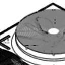
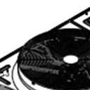
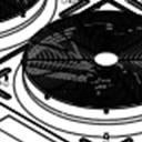
5 Product Description SEMI-HERMETIC YORK TWIN SCREW COMPRESSORS The direct-drive, semi-hermetic rotary twin-screw compressors incorporate advanced technology in a rugged design. The continuous function, microprocessor controlled VSD provides smooth capacity control from 100% down to 10% of chiller capacity. State-of-the-art technology, obtained from decades of screw compressor design and manufacturing by FRICK, ensures optimal efficiencies at all chiller load points. With no unloading steps or slide valves in the compressors, the YVAA variable speed driven compressors have 50% fewer moving parts than fixed speed compressors with slide valves. The YVAA compressor is one of the most efficient and reliable screw compressors in the industry. EVAPORATOR The evaporator is a shell and tube, hybrid falling film type heat exchanger. It contains a balance of flooded and falling film technology to optimize efficiency, minimize refrigerant charge, and maintain reliable control. A specifically designed distribution system provides uniform refrigerant flow for optimum performance. CONDENSER The YVAA introduces the microchannel coil to the YORK screw compressor chiller line. Microchannel coils are made of a single material to avoid galvanic corrosion due to dissimilar metals. Coils and headers are brazed as one piece, minimizing leaks. The inherently rugged coil construction, which includes non-overhanging fins, eliminates the possibility of fin damage. The microchannel maximizes condenser heat transfer, resulting in a smaller footprint, and reduces refrigerant charge by as much as 50%. The condenser fans are composed of corrosion resistant aluminum hub and glass-fiber-reinforced polypropylene composite blades molded into a low-noise airfoil section. All blades are statically and dynamically balanced for vibration-free operation. Fan motors are Totally Enclosed Air-Over (TEAO), squirrel-cage type and current protected. The direct drive motors feature double-sealed and permanently lubricated ball bearings, cutting down on maintenance cost over the life of the unit. REFRIGERANT CIRCUIT The YVAA has one independent refrigerant circuit per compressor. Each circuit uses copper refrigerant pipe formed on computer-controlled bending machines. By using computer-aided technology, over 60% of system piping brazed joints have been eliminated (as compared to designs that use fittings), resulting in a highly reliable and leak-resistant system. COMPLETE FACTORY PACKAGE Each unit is shipped as a complete factory package, completely assembled with all interconnecting refrigerant piping and internal wiring and ready for field installation. Prior to shipment, each individual chiller undergoes an extensive testing procedure, ensuring workmanship is the highest quality and that the initial start-up is trouble-free. Before leaving the factory, each refrigerant circuit is factory pressure tested, evacuated and then fully charged with R134a refrigerant and oil. An operational test is performed with water flowing through the evaporator to ensure each circuit functions correctly. ELECTRICAL All controls and motor starting equipment necessary for unit operation are factory wired and function tested. There are no surprises when you go to start-up; you can have confidence that the unit will start up right the first time and every time. The chillers come with a single point power connection and are supplied with a factory mounted and wired control transformer that powers all unit controls from the main unit power supply. The transformer utilizes scheduled line voltage on the primary side and provides 115V/1Ø on secondary. The standard unit is equipped with terminal block electrical connections. All exposed power wiring is routed through liquid-tight, UV-stabilized, non-metallic conduit. VSD Power/Control Panel includes main power connection(s), VSD and fan motor contactors, current overloads, and factory wiring. All display and control features can be accessed through the keypand and control display access door, eliminating the need to open the main cabinet doors. BUILDING AUTOMATION SYSTEM CAPABILITIES The E-Link Gateway provides an economical and versatile connection between Johnson Controls equipment and open/standard protocols. It efficiently manages the communication protocols currently used by Johnson Controls equipment, exposing the data in a consistent, organized, and defined fashion. A simple switch selection allows configuration of the required equipment profile and output protocol, which reduces equipment connectivity startup time. JOHNSON CONTROLS 5


 VSD Output Frequency")
 Chilled Liquid Pump Status 6 Evaporator Heater Status")
 Local or")


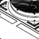
6 MicroComputer Control Center FIG.1 VIEW OF YORK CONTROL CENTER KEYPAD AND DISPLAY MICROCOMPUTER CONTROL CENTER The microcomputer control center (see Figure 1) provides automatic control of chiller operation including compressor start/ stop and load/unload anti-recycle timers, condenser fans, chilled liquid pump, evaporator heater, unit alarm contacts and run signal contacts. The microcomputer control center comes online as soon as the main power switch on the unit is switched on; immediately, the microcomputer control center will begin to continuously monitor all variables. The microprocessor controls the unit s capacity by matching the actual leaving chilled liquid temperature (LCHLT) to the user-defined setpoint. Factors that may cause the system s actual LCHLT to fluctuate are changes in ambient temperature, load, and chilled liquid loop flow rate and volume. The controls system reacts to such changes by adjusting the number of compressors that are on and the loading of each compressor in order to keep the LCHLT at the setpoint. The controls system logic monitors the rate at which the LCWT is approaching the setpoint to ramp up or down compressor capacity as required. The variable frequency drive allows the compressor capacity to match the load. Display Data Leaving Chilled Liquid Temperature Returning Liquid Temperature Ambient Temperature Lead System Compressor Capacity (% of Full Load Amps) VSD Output Frequency / Compressor Speed Compressor Run Hours Compressor Number of Starts Oil Pressure and Temperature (per Compressor) Chilled Liquid Pump Status 6 Evaporator Heater Status History Data for Last Twenty Normal Shutdowns History Data for Last Ten Shutdown Faults Programmable Setpoints Chiller on/off Chilled Liquid (Water or Glycol) Local or Remote Control Units of Measure (Imperial or SI) System Lead/Lag Remote Temperature Reset Remote Current Limit Leaving Chilled Liquid Temperature Setpoint and Range Johnson Controls systems or another vendor s systems can incorporate these setpoints and data outputs to give the customer a complete understanding of how the system is running through a Building Automation System. Extreme Conditions - During extreme or unusual conditions (i.e. blocked condenser coils, ambient above scheduled maximum, etc.) the chiller control system will avoid shutdown by varying capacity. By monitoring motor current and suction and discharge pressures, the chiller can maintain maximum available cooling output without shutting down. Unit Safeties are provided for the chiller to perform autoreset shut down for the following conditions: Ambient temperature above or below allowable range Out of range leaving chilled liquid temperature Under voltage Flow switch operation JOHNSON CONTROLS
7 Accessories and Options All options factory mounted unless otherwise noted. SOUND ATTENUATION LOW NOISE KITS The standard chiller configuration is equipped with low sound fans and acoustic treatments on the refrigerant lines and compressors. There are several sound attenuation options available to further reduce sound at its source thereby meeting local sound level regulations. SilentNight - Due to time of day based sound regulations in some locations it may be desirable to force the chiller to a lower sound level on demand. The SilentNight control option provides a control input to limit sound output of the chiller based on time of day. This feature is programmable at the chiller panel or can be controlled remotely via a signal (4-20mA or 0-10 VDC) from a BAS system. ULTRA QUIET FANS The chiller is equipped with specially designed fans and motors to provide lower sound levels yet retain appropriate airflow. The result is reduced fan generated sound with minimal effect on the chiller capacity or efficiency at standard AHRI conditions. The fans are three-bladed for 60Hz and five-bladed for 50Hz. FAN OPTIONS HIGH STATIC FANS - (380V/60 Hz, 460V/60 Hz, 400V/50 Hz) The chiller is equipped with condenser fans with higher power motors suitable for high external static pressure, up to 100Pa (0.4 in. water), across condenser coils. This option should be selected if additional airflow resistance may be present due to flow restrictions such as field installed ducts, filters, sound enclosures etc. Please contact your local Johnson Controls representative for more information. HIGH AIRFLOW FANS - (380V/60 Hz, 460V/60 Hz, and 400V/50 Hz) The chiller is equipped with condenser fans with airfoil type blades and high power motors providing extra airflow across coils. In some chiller configurations, this option can provide an increase in chiller capacity at high ambient. Please contact your local Johnson Controls representative for more information. CONDENSER COIL PROTECTION The aluminum alloys used in the YVAA microchannel condenser have been carefully selected and tested for high corrosion resistance. However, all metals can corrode in harsh conditions. Consider protecting coils from corrosive environments such as coastal, marine, urban and industrial. POST-COATED EPOXY DIPPED CONDENSER Microchannel condenser coils applied with electro-deposited and baked flexible epoxy coating that is finished with a polyurethane UV resistant top-coat suitable for highly corrosive applications. PROTECTIVE CHILLER PANELS WIRE PANELS UV stabilized black polyvinyl chloride coated, heavy gauge, welded wire mesh guards mounted on the exterior of the full unit. Protects condenser coil faces and prevents unauthorized access to refrigerant components (compressors, pipes, evaporator, etc.), yet provides free air flow. This can cut installation cost by eliminating the need for separate, expensive fencing. See Figure 2. LOUVERED PANELS Louvered panels, painted the same color as the unit, enclose the unit to visually screen and protect the coils as well as prevent unauthorized access to internal components. Also available as a condenser-only option. See Figures 3 and 4. LOUVERED/WIRE PANELS COMBINATION - Louvered panels, painted the same color as the unit, are mounted on external condenser coil faces. Heavy gauge, welded wire-mesh panels, coated to resist corrosion, are mounted around base of machine to restrict unauthorized access. See Figure 5. END HAIL GUARD Louvered panels, painted the same color as the unit, are installed on the rear of the unit (opposite end of the control panel) to protect the exposed condenser from flying debris or hail. See Figure 6. V-GUARD PANELS Solid panels, painted the same color as the unit, are installed along the sides of the units to cover exposed piping within the condenser section without impacting airflow. These guard panels can be combined with End Hail Guard option for additional protection from debris. See Figure 7. JOHNSON CONTROLS 7
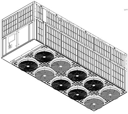


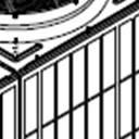
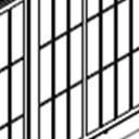
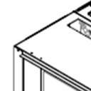


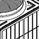
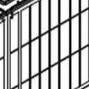
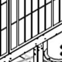
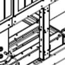
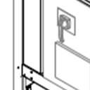
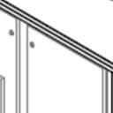
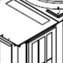
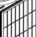
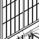
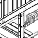
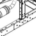
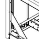
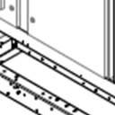
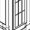
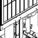
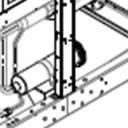


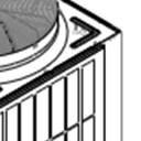


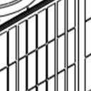
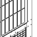
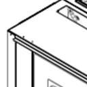

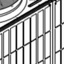
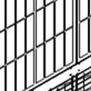
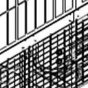
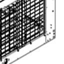
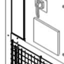
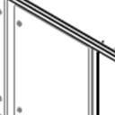
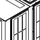
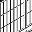
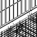
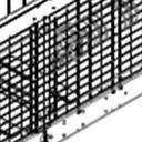
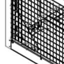

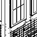

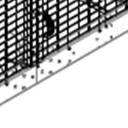
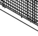
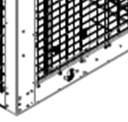
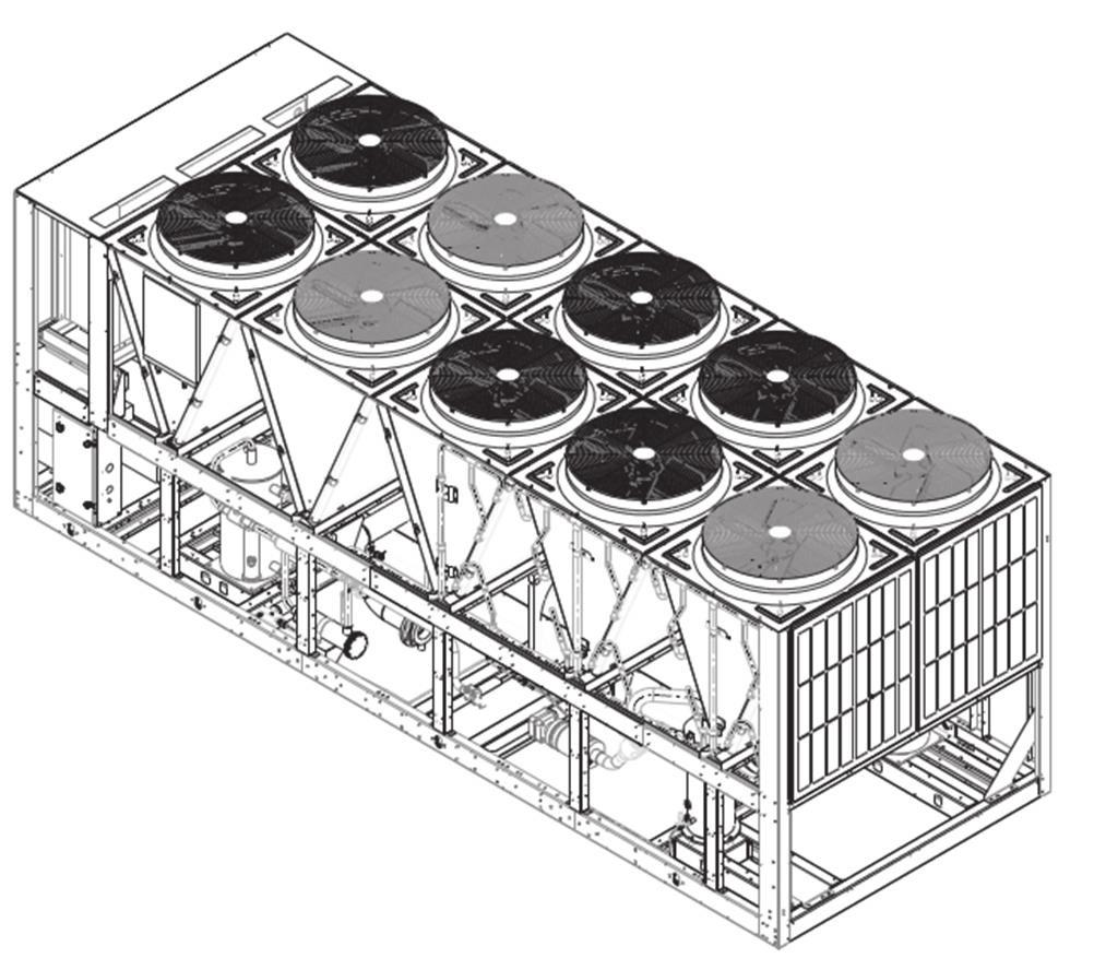
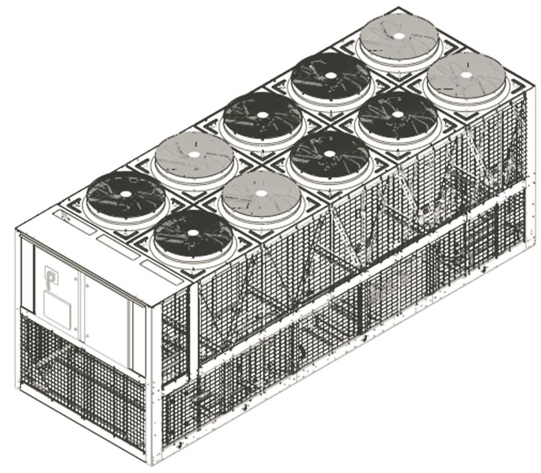
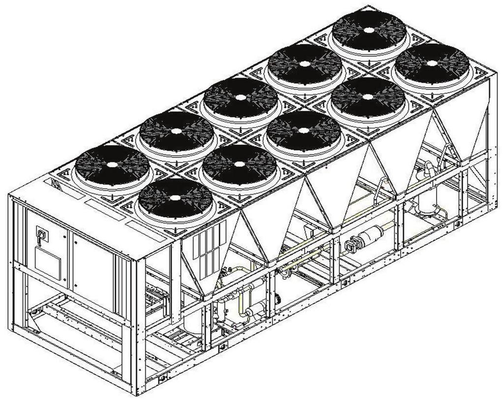
8 Accessories and Options - continued FIG. 2 FULL UNIT WIRE PANELS FIG.5 LOUVERED/WIRE PANELS COMBINATION FIG. 3 FULL UNIT LOUVERED PANELS FIG. 6 END HAIL GUARD FIG. 4 CONDENSERS-ONLY LOUVERED PANELS 8 FIG. 7 V-GUARD OPTION JOHNSON CONTROLS
9 EVAPORATOR OPTIONS 1-1/2 INSULATION Double thickness insulation provided. FLANGE KIT Provides contractor with the couplings best suited to tie into the chilled liquid piping. All flanges are ANSI 150 psig (10.3 barg). Field mounted. Options include: ANSI/AWWA C-606 flanges - 2 flanges, for applications where field piping has existing flanges. ANSI/AWWA C-606 flanges - 4 flanges, for applications where customer wants flanged connections which do not exist on the field piping. Weld flanges - 2 flanges, for customer to weld to evaporator to mate to existing flanges on field piping. Weld flanges - 4 flanges, for customer to weld to evaporator and customer wants flanged connections which do not exist on the field piping CONNECTION LOCATION - The standard unit configuration is available with liquid inlet connections at rear (opposite control panel end) of unit. Option available for front fluid inlet on select configurations. THREE-PASS The standard evaporator is constructed with two chilled water passes through the evaporator. The three-pass option is recommended for use in brine applications or where a greater water temperature difference is required but efficiency cannot be sacrificed. WATER BOX HEATER - The standard unit comes with freeze protection on the evaporator down to 0 F (-17.8 C). The waterbox heater option provides additional freeze protection down to -20 F (-28 C). CONTROLS OPTIONS HIGH AMBIENT OPERATION (400V/50Hz and 380V/60Hz only) This provides special control logic coupled with high airflow fans to permit high ambient (up to 125 F (52 C)) operation. This option may also allow for increased machine capacity, allowing the selection of a smaller chassis to meet specific capacity requirements. BUILDING AUTOMATION SYSTEM INTERFACE (TEM- PERATURE) - Factory installed option to accept a 4 to 20 ma or a 0 to 10 VDC input to allow remote reset of the Leaving Chilled Liquid Temperature Setpoint. The setpoint can be positively offset upwards up to 40 F (22.2 C). This option is useful for ice storage or process applications or for periods where higher chilled liquid temperatures are adequate for low loads. Available alone or in combination with BAS Load Limit. BUILDING AUTOMATION SYSTEM INTERFACE (LOAD LIMIT) - Factory installed option to accept a 4 to 20 ma or a 0 to 10 VDC input to allow remote reset of the Load Limit Setpoint. The setpoint can limit system demand from %. Available alone or in combination with BAS Temperature Reset. E-Link The E-Link gateway provides full communication to Building Automation Systems, including BACnet (MS/ TP), Modbus, LON and N2. THERMAL STORAGE Provides special control logic and modifications to produce leaving chilled brine temperatures below 40 F (4.4 C) primarily at times of low ambient temperatures (night time). Option can be used to produce ice to supplement cooling and significantly decrease energy costs. The capability of the chiller is enhanced by using both ice and chilled liquid simultaneously during times of peak cooling needs. GENERAL OPTIONS FLOW SWITCH ACCESSORY - Vapor proof SPDT, NEMA 3R switch, 150 psig (10.3 barg) DWP, -20 F to 250 F (-29 C to 121 C) with 1 NPT (IPS) connection for upright mounting in horizontal pipe (This flow switch or equivalent must be furnished with each unit). Field mounted. DIFFERENTIAL PRESSURE SWITCH This 3-45 psig (0.2-3 barg) range switch, with 1/4 NPTE pressure connections, is an alternative to the paddle-type flow switch. Field mounted. SERVICE ISOLATION VALVE Service suction isolation valve added to unit for each refrigerant circuit. CHICAGO CODE RELIEF VALVE - Special relief valves per Chicago code. DUAL PRESSURE RELIEF VALVE Two safety relief valves are mounted in parallel; one is always operational to assist in valve replacement during maintenance. PRESSURE VESSEL OPTIONS The evaporator can be provided with either ASME or PED pressure vessel codes certification. CIRCUIT BREAKER A unit-mounted circuit breaker with external lockable handle will be supplied to isolate the single point power voltage for servicing. The circuit breaker is sized to provide motor branch circuit protection, short circuit protection and ground fault protection for the motor branch-circuit conductors, the motor control apparatus and the motors. JOHNSON CONTROLS 9
10 Accessories and Options - continued NON-FUSED DISCONNECT SWITCH Unit-mounted disconnect switch(es) with external lockable handle can be supplied to isolate the unit power voltage for servicing. Separate external fusing must be supplied by the power wiring, which must comply with local codes. SPECIAL REQUIRMENT DOCUMENTS There are two options to select from: Special Requirement Document Package (SRDP) includes Pressure Vessel Report, Unit Run Test Report, Production System Check Sheet and Final Unit Inspection Check Sheet. Materials Package includes steel mill material reports for vessels in addition to the SRDP. 1 SPRING ISOLATORS Spring and cage type isolators for mounting under the unit base rails are available to support unit. They are level adjustable. 1 nominal deflection may vary slightly by application. Field mounted. 2 RESTRAINED SPRING ISOLATORS Restrained Spring-Flex Mounting isolators incorporate a rugged welded steel housing with vertical and horizontal limit stops. Housings designed to withstand a minimum 1.0g accelerated force in all directions up to 2 (51mm). The deflection may vary slightly by application. They are level adjustable. Field mounted. VIBRATION ISOLATION ELASTOMERIC ISOLATION This option is recommended for normal installations. It provides very good performance in most applications for the least cost. Field mounted. 10 JOHNSON CONTROLS


11 Refrigerant Piping Layout Low pressure refrigerant (liquid and gas) enters the evaporator and is sprayed across the top of the tube bundle from spray nozzles. The liquid refrigerant from the nozzles gravity drains down across the tube bundle and is evaporated and superheated by the heat energy absorbed from the chilled liquid passing through the tubes. The low pressure refrigerant vapor leaves the top of the evaporator and enters the compressor where the refrigerant vapor is compressed and the pressure and superheat are increased. The high pressure superheated gas enters the air cooled condenser where heat is rejected via the condenser coils and fans. The fully condensed and sub-cooled liquid leaves the air cooled condenser, flows through the filter drier and enters the economizer tank. The flow of refrigerant into the economizer is controlled by the electronic expansion valve. Additional cooling of the refrigerant liquid may take place in the economizer tank when the economizer valve is opened. After leaving the economizer tank, liquid refrigerant flows through an orifice where pressure reduction and further cooling take place. The low pressure refrigerant (liquid and gas) then enters the evaporator. JOHNSON CONTROLS 11
12 Application Data UNIT SIZING Avoid over-sizing a chiller. Properly sized chillers operate stably and provide the best life cycle cost. When designing phased projects, select multiple small chillers to match demand for each phase. Use multiple small chillers when the minimum cooling demand is less than 10% of the maximum cooling demand. UNIT LOCATION The YVAA chillers are designed for outdoor installation. To achieve optimum performance and trouble-free service provide adequate space around chillers (see Figure 8). When selecting chiller installation sites, follow these requirements: 1. Installation sites may be either on a roof or on ground level. (See FOUNDATION) 2. Provide space for air to flow into condensers per dimensions shown on the dimension drawing on pgs 20 and 21. Restricted airflow or hot air recirculation will diminish performance. Johnson Controls unit controls will optimize the operation without nuisance high pressure safety cutouts; however, the system designer MUST consider potential performance degradation. Recommended clearances (See Fig. 8) for all units are as follows: 12 a. Access to the unit control center stipulates the unit is no higher than on spring isolators. b. Recommended minimum clearances: i. Side to wall 6 (1.8m) ii. Rear to wall 6 (1.8m) iii. Control panel end to wall 4 (1.2m) iv. Top no obstructions whatsoever v. Distance between adjacent units 10 (3m) c. No more than one wall around the chiller yard should be higher than the chiller(s) 3. Avoid locations near windows or structures where normal operating sounds may be objectionable. 4. The condenser fans are propeller-type and are not recommended for use with ductwork, filters or other impediments to airflow in the condenser air stream. 5. When obstructions to airflow exist, they must not add more than 0.1 external static pressure. 6. Protection against corrosive environments is available by ordering the units with cured epoxy-coating on the condenser microchannel. Epoxy-coated coils should be used with any units being installed at the seashore, or where salt spray may hit the units, or where acid rain is prevalent. 7. On installations where winter operation is intended and snow accumulations are expected, additional elevation must be provided to insure normal condenser air flow. 8. Provide adequate space for tubes to be removed from evaporator. For clearances please contact your nearest Johnson Controls Sales Office. FOUNDATION FIG 8. ACCEPTABLE MINIMUM CLEARANCES AROUND/BETWEEN UNIT(S) FOR PROPER AIRFLOW Mount units on a flat and level foundation, ground or roof, capable of supporting the entire operating weight of the equipment. Please contact your nearest Johnson Controls Sales Office for shipping and operating weights. Roof Locations Provide structure to safely support the entire weight of the unit and service personnel. Do not damage the roof during installation. If the roof is bonded, consult a building contractor or architect for special installation requirements. Use spring isolators to minimize vibration transmission into building structure. Provide additional structural support at the spring-isolator locations. Ground Locations Units must be installed on a substantial base that will not settle and cause strain on the refrigerant lines, resulting in possible leaks. A one-piece concrete slab, with footers extending below the frost line is recommended. The slab should not be tied to the main building foundation as operational noise will telegraph. Mounting holes (5/8 ) are provided in the base rails for bolting the unit to its foundation. See ISOLATOR LOCA- TIONS on page 54 for location of the mounting holes. For ground installations, precautions should be taken to protect the unit from tampering by, or injury to, unauthorized persons. Fasteners on access panels will prevent JOHNSON CONTROLS
13 casual tampering; however, further safety precautions such as unit enclosure options, a fenced-in enclosure, or locking devices on the panels may be advisable. Check local authorities for safety regulations. Seismic Applications Avoid installing chillers on springs or roofs where earthquakes are a risk. Springs and roofs amplify earthquake forces. Rigidly mounting chillers to ground level concrete pads is typically the best option for earthquake zones. Contact Johnson Controls equipment specialists for help with projects that have seismic requirements. CHILLED LIQUID PIPING Design the chilled liquid piping system so that the circulating pump discharges into the evaporator. The inlet and outlet evaporator-liquid connections are given in DIMEN- SIONS. Hand stop valves are recommended in all lines to facilitate servicing. Provide drain connections at low points to permit complete drainage of the evaporator and system piping. that the gallon/ton ratio be within the 5 to 8 (5.4 to 8.6 liter/cooling KW) range for constant flow rate chilled liquid systems. See VARIABLE PRIMARY FLOW for recommendations for VPF systems. For process applications, a minimum of 6 gallons/ton (6.5 liter/cooling KW) ratio is recommended with preference towards a range of 7 to 11 (7.5 to 11.8). Install a tank or increase pipe sizes to provide sufficient liquid volume. LEAVING LIQUID TEMPERATURE OUT OF RANGE The YVAA chiller line has a maximum leaving liquid temperature of 60 F (15.6 F). Some process applications require a chilled liquid temperature higher than what the chiller provides. In those applications, a simple piping change can remove the problem. By using a mixture of chiller-cooled liquid and returning process liquid, the chilled liquid entering the process can be held at the desired temperature. (A tank can also be used to meet high leaving liquid temperature requirements.) (See Figure 9) The evaporator must be protected by a strainer, preferably of 40 mesh, fitted as close as possible to the liquid inlet connection, and provided with a means of local isolation. The evaporator must not be exposed to flushing velocities or debris released during flushing. It is recommended that a suitably sized bypass and valve arrangement is installed to allow flushing of the piping system. The bypass can be used during maintenance to isolate the heat exchanger without disrupting flow to other units. Pressure-gauge connections are recommended for installation in the inlet and outlet liquid lines. Gauges are not provided with the unit and are to be furnished by others. Chilled liquid lines exposed to the weather should be wrapped with a supplemental heater cable and insulated, or glycol should be added to the chilled liquid to protect against freezing if low-ambient periods are expected. A flow switch is available as an accessory on all units. A flow switch must be installed in the leaving liquid piping of the evaporator and must not be used to start and stop the unit. MINIMUM LIQUID VOLUME It is good practice to include as much liquid volume as possible in a chilled liquid loop. This increases the thermal mass and Flywheel effect within the system (i.e. the more the better) which in turn promotes stable liquid temperature control and increases reliability by reducing compressor cycling. For air conditioning applications, a minimum of 3 gallons/ ton (3.2 liters/cooling KW) is recommended. It is preferred FLOW RATE OUT OF RANGE FIG. 9 LEAVING LIQUID TEMPERATURE OUT OF RANGE SUGGESTED LAYOUT Each YVAA evaporator has a minimum and maximum flow rate. Some process applications require a flow rate that is out of range for the evaporator. In those applications, a piping change can remove the problem. In applications where the required flow rate is less than the evaporator s minimum allowable, the chilled liquid can be recirculated to the chiller. (See Figure 10, pg 14) In applications where the required flow rate is greater than the evaporator s maximum allowable, the chilled liquid can be recirculated to the load (see Figure 11, pg 14). JOHNSON CONTROLS 13
14 Application Data - continued FIG. 10 SUGGESTED LAYOUT FOR APPLICATIONS WITH A FLOW RATE LESS THAN THE EVAPO- RATOR MINIMUM ALLOWABLE FLOW RATE FIG. 11 SUGGESTED LAYOUT FOR APPLICATIONS WITH A FLOW RATE GREATER THAN THE EVAPORATOR MAXIMUM ALLOWABLE FLOW RATE THERMAL STORAGE Thermal storage is the practice of storing cooling energy during a period of little or no load and/or low energy costs for use during periods of high load and/or energy costs. Conventional cooling systems produce cooling when it is needed which is commonly during times of peak demand. Thermal storage allows generation of cooling capacity to occur during off-peak periods and store that capacity to meet future cooling requirements. Using thermal storage can result in smaller equipment sizes, thereby reducing capital cost, and also can result in significant energy cost savings. VARIABLE PRIMARY FLOW Johnson Controls recommends a maximum 10% per minute flow rate of change, based on design flow, for variable primary flow applications. Eight to 10 gallons per chiller ton (8.6 to 10.8 liter per cooling KW) is recommended for the system liquid volume. Insufficient system volume and rapid flow changes can cause control problems or can even cause chiller shutdowns. There are many other design issues to evaluate with variable primary flow systems. Consult your Johnson Controls Sales Office for more information about successfully applying YVAA chillers. The YVAA has special control logic to be able to produce chilled leaving brine temperatures below 40 F (4.4 C) so as to supply a storage tank with chilled liquid during times of low demand. YVAA chillers selected for thermal storage operation can also be selected to efficiently provide chilled liquid at nominal cooling loads. 14 JOHNSON CONTROLS
15 INTENTIONALLY LEFT BLANK JOHNSON CONTROLS 15
16 Physical Data - English The data shown in this table is applicable to selected typical configurations. Other configurations are available through our configuration/selection software. Please contact your nearest Johnson Controls Sales Office for the chiller configuration that best matches your specific needs. UNIT FRAME CONDENSER CODE EVAPORATOR CODE B B C A A B C A C C B C C GENERAL UNIT DATA Number of Independent Refrigerant Circuits 2 Refrigerant Charge, R-134a, Ckt.-1/Ckt.-2, lbs 175/ / / / / / / / / / / / /250 Oil Charge, Ckt.-1/Ckt.-2, gal 2.1/ / / / / / / / / / / / /2.9 % Minimum Load 10% Unit shipping weight, lbs Operating Weight, lbs Chassis Dimensions - Length, Ft Chassis Dimensions - Width, Ft Chassis Dimensions - Height, Ft COMPRESSORS, SEMI-HERMETIC SCREW Qty per Chiller 2 CONDENSER FANS Number Ckt-1/Ckt-2 4/4 5/5 6/6 6/4 7/5 8/6 4/4 6/6 6/6 7/7 7/5 8/6 8/8 Air on Condenser (Min/Max), F 0/125 EVAPORATOR, SHELL AND TUBE HYBRID FALLING FILM 2 Water Volume, gal Leaving Water Temperature (Min/Max), F 3 40/60 Maximum Water Side Pressure, psig 150 Maximum Refrigerant Side Pressure, psig 235 Evap Drain Conection, in 3/4 NOTES: 1. Shipping and operating weights shown are for base unit; selected options may add weight to unit. Contact your nearest Johnson Controls Sales office for weight data. 2. The evaporator is protected against freezing to 0 F(-17.8 C) with a standard heater. 3. For leaving liquid temperature below 40 F(4.4 C) or above 60 F (15.6 C), contact your nearest Johnson Controls Sales Office for application requirements. 16 JOHNSON CONTROLS
17 The data shown in this table is applicable to selected typical configurations. Other configurations are available through our configuration/selection software. Please contact your nearest Johnson Controls Sales Office for the chiller configuration that best matches your specific needs. UNIT FRAME CONDENSER CODE EVAPORATOR CODE B D E E E C C E E E C E E GENERAL UNIT DATA Number of Independent Refrigerant Circuits 2 Refrigerant Charge, R-134a, Ckt.-1/Ckt.-2, lbs 210/ / / / / / / / / / / / /315 Oil Charge, Ckt.-1/Ckt.-2, gal 2.7/ / / / / / / / / / / / /4.3 % Minimum Load 10% Unit shipping weight, lbs Operating Weight, lbs Chassis Dimensions - Length, Ft Chassis Dimensions - Width, Ft Chassis Dimensions - Height, Ft COMPRESSORS, SEMI-HERMETIC SCREW Qty per Chiller 2 CONDENSER FANS Number Ckt-1/Ckt-2 7/7 7/7 7/7 8/8 9/7 9/7 10/8 10/8 10/10 8/8 9/9 9/9 10/10 Air on Condenser (Min/Max), F 0/125 EVAPORATOR, SHELL AND TUBE HYBRID FALLING FILM 2 Water Volume, gal Leaving Water Temperature (Min/Max), F 3 40/60 Maximum Water Side Pressure, psig 150 Maximum Refrigerant Side Pressure, psig 235 Evap Drain Conection, in 3/4 NOTES: 1. Shipping and operating weights shown are for base unit; selected options may add weight to unit. Contact your nearest Johnson Controls Sales office for weight data. 2. The evaporator is protected against freezing to 0 F(-17.8 C) with a standard heater. 3. For leaving liquid temperature below 40 F(4.4 C) or above 60 F (15.6 C), contact your nearest Johnson Controls Sales Office for application requirements. JOHNSON CONTROLS 17
18 Physical Data - SI The data shown in this table is applicable to selected typical configurations. Other configurations are available through our configuration/selection software. Please contact your nearest Johnson Controls Sales Office for the chiller configuration that best matches your specific needs. UNIT FRAME CONDENSER CODE EVAPORATOR CODE B B C A A B C A C C B C C GENERAL UNIT DATA Number of Independent Refrigerant Circuits 2 Refrigerant Charge, R-134a, Ckt.-1/Ckt.-2, kg 80/80 86/86 102/102 80/70 86/78 100/89 93/93 80/80 102/ /109 96/86 114/ /114 Oil Charge, Ckt.-1/Ckt.-2, liters 8.0/ / / / / / / / / / / / /11.1 % Minimum Load 10% Unit Shipping Weight, kg Operating Weight, kg Chassis Dimensions - Length, mm Chassis Dimensions - Width, mm Chassis Dimensions - Height, mm COMPRESSORS, SEMI-HERMETIC SCREW Qty per Chiller 2 CONDENSER FANS Number Ckt-1/Ckt-2 4/4 5/5 6/6 6/4 7/5 8/6 4/4 6/6 6/6 7/7 7/5 8/6 8/8 Air on Condenser (Min/Max), C -17.8/51.7 EVAPORATOR, SHELL AND TUBE HYBRID FALLING FILM 2 Water Volume, liters Leaving Water Temperature (Min/Max), C 3 4.4/15.6 Maximum Water Side Pressure, bar 10.3 Maximum Refrigerant Side Pressure, bar 16.2 Evap Drain Conection, in 3/4 NOTES: 1. Shipping and operating weights shown are for base unit; selected options may add weight to unit. Contact your nearest Johnson Controls Sales office for weight data. 2. The evaporator is protected against freezing to 0 F(-17.8 C) with a standard heater. 3. For leaving liquid temperature below 40 F(4.4 C) or above 60 F (15.6 C), contact your nearest Johnson Controls Sales Office for application requirements. 18 JOHNSON CONTROLS
19 The data shown in this table is applicable to selected typical configurations. Other configurations are available through our configuration/selection software. Please contact your nearest Johnson Controls Sales Office for the chiller configuration that best matches your specific needs. UNIT FRAME CONDENSER CODE EVAPORATOR CODE B D E E E C C E E E C E E GENERAL UNIT DATA Number of Independent Refrigerant Circuits 2 Refrigerant Charge, R-134a, Ckt.-1/Ckt.-2, kg 96/96 120/ / / / / / / / / / / /143 Oil Charge, Ckt.-1/Ckt.-2, liters 10.1/ / / / / / / / / / / / /16.3 % Minimum Load 10% Unit Shipping Weight, kg Operating Weight, kg Chassis Dimensions - Length, mm Chassis Dimensions - Width, mm Chassis Dimensions - Height, mm COMPRESSORS, SEMI-HERMETIC SCREW Qty per Chiller 2 CONDENSER FANS Number Ckt-1/Ckt-2 7/7 7/7 7/7 8/8 9/7 9/7 10/8 10/8 10/10 8/8 9/9 9/9 10/10 Air on Condenser (Min/Max), C -17.8/51.7 EVAPORATOR, SHELL AND TUBE HYBRID FALLING FILM 2 Water Volume, liters Leaving Water Temperature (Min/Max), C 3 4.4/15.6 Maximum Water Side Pressure, bar 10.3 Maximum Refrigerant Side Pressure, bar 16.2 Evap Drain Conection, in 3/4 NOTES: 1. Shipping and operating weights shown are for base unit; selected options may add weight to unit. Contact your nearest Johnson Controls Sales office for weight data. 2. The evaporator is protected against freezing to 0 F(-17.8 C) with a standard heater. 3. For leaving liquid temperature below 40 F(4.4 C) or above 60 F (15.6 C), contact your nearest Johnson Controls Sales Office for application requirements. JOHNSON CONTROLS 19
20 Evaporator Options YVAA MODEL FRAME COND. EVAP. ENGLISH - ALL DIMENSIONS IN INCHES STANDARD (TWO-PASS, REAR OPTIONAL THREE-PASS REAR INLET/OUTLET) EVAPORATOR INLET/FRONT OUTLET EVAPORATOR MINIMUM MAXIMUM MINIMUM A C D F CHILLED CHILLED CHILLED C-606 WATER C-606 WATER WATER WATER WATER CONN. VOL. A B C E F CONN. VOL. FLOW FLOW FLOW SIZE GAL SIZE GAL RATE RATE RATE GPM GPM GPM MAXIMUM CHILLED WATER FLOW RATE GPM B B C A A B C A C C B C C B D E E E C C E E E C E E JOHNSON CONTROLS
21 YVAA MODEL SI- ALL DIMENSIONS IN MM STANDARD (TWO-PASS, REAR INLET/OUTLET) EVAPORATOR OPTIONAL THREE-PASS REAR INLET/FRONT OUTLET EVAPORATOR FRAME COND. EVAP. A C D G C-606 CONN. SIZE WATER VOL. LITERS MINIMUM CHILLED WATER FLOW RATE l/s MAXIMUM CHILLED WATER FLOW RATE l/s A B E F G C-606 CONN. SIZE WATER VOL. LITERS MINIMUM CHILLED WATER FLOW RATE l/s MAXIMUM CHILLED WATER FLOW RATE l/s B B C A A B C A C C B C C B D E E E C C E E E C E E JOHNSON CONTROLS 21
22 Dimensions The data shown in this table is applicable to selected typical configurations. Other configurations are available through our configuration/selection software. Please contact your nearest Johnson Controls Sales Office for the chiller configuration that best matches your specific needs. ENGLISH AND SI DIMENSIONS 22 JOHNSON CONTROLS
23 INTENTIONALLY LEFT BLANK JOHNSON CONTROLS 23
24 Rigging Hole Locations ENGLISH YVAA MODEL DESCRIPTION A B C D E F G H I J K L M N CENTER OF GRAVITY FRAME COND EVAP X (IN) Y (IN) B Rigging Hole Location (in) Point Load (lbs) B Rigging Hole Location (in) Point Load (lbs) C Rigging Hole Location (in) Point Load (lbs) A Rigging Hole Location (in) Point Load (lbs) A Rigging Hole Location (in) Point Load (lbs) B Rigging Hole Location (in) Point Load (lbs) C Rigging Hole Location (in) Point Load (lbs) A Rigging Hole Location (in) Point Load (lbs) C Rigging Hole Location (in) Point Load (lbs) C Rigging Hole Location (in) Point Load (lbs) B Rigging Hole Location (in) Point Load (lbs) C Rigging Hole Location (in) Point Load (lbs) NOTE: Weights shown for base unit; selected options may add weight to unit. Contact your nearest Johnson Controls Sales Office for weight data. 24 JOHNSON CONTROLS
Model YVAA Air-Cooled Screw Compressor Liquid Chillers With Variable Speed Drive Style A
 Model YVAA Air-Cooled Screw Compressor Liquid Chillers With Variable Speed Drive Style A 150-500 Tons 525-1750 kw 2 Compressor 50 and 60 Hz HFC-134a Nomenclature YVAA 021 3 A X X 46 A A REFRIGERANT HFC
Model YVAA Air-Cooled Screw Compressor Liquid Chillers With Variable Speed Drive Style A
 FORM 201.28-EG1 (7) Model YVAA Air-Cooled Screw Compressor Liquid Chillers With Variable Speed Drive Style A 150-500 Tons 525-1750 kw 2 Compressor 50 and 60 Hz HFC-134a or HFC-513A FORM 201.28-EG1 (7)
MODEL QTC4 AIR-COOLED SCREW CHILLERS
 MODEL QTC4 AIR-COOLED SCREW CHILLERS 150-360 Tons 2 Compressor 60 Hz HFC-134a or HFC-513A Nomenclature QTC4 2 SAXX 46 A A DEVELOPMENT LEVEL REFRIGERANT A= HFC-134a B = HFC-513A MODEL NUMBER QTC4 = Quantech
Model YVFA Air-Cooled Liquid Chillers With VSD Screw Compressor And Integrated Free Cooling Style A
 Model YVFA Air-Cooled Liquid Chillers With VSD Screw Compressor And Integrated Free Cooling Style A 115-380 Tons 400-1340 kw 2 Compressor 50 and 60 Hz HFC-134a Nomenclature YVFA 025 9 B X X 46 A A REFRIGERANT
Model YCIV Air-Cooled Screw Liquid Chillers with Variable Speed Drive Style A
 Model YCIV Air-Cooled Screw Liquid Chillers with Variable Speed Drive Style A 150-400 TONS (527-1407 kw) 2, 3, and 4 Compressor 60 Hz Design Series H Nomenclature YC I V 0207 H A XX XX = VOLTAGE CODE A
FORM EG2 (405) Air Cooled Screw Liquid Chillers STYLE A FPO 28971AR. R134a kw 50 Hz
 Air Cooled Screw Liquid Chillers STYLE A FPO 28971AR. R134a kw 50 Hz") FORM 201.21-EG2 (405) Air Cooled Screw Liquid Chillers STYLE A FPO 28971AR R134a 492-879 kw 50 Hz TABLE OF CONTENTS Introduction...3 Specifications...4 Accessories and Options...7 Temperatures and Flows...10
FORM 201.21-EG2 (405) Air Cooled Screw Liquid Chillers STYLE A FPO 28971AR R134a 492-879 kw 50 Hz TABLE OF CONTENTS Introduction...3 Specifications...4 Accessories and Options...7 Temperatures and Flows...10
Call us today! (800)
") 150 TON AIR-COOLED CHILLER PA-ACCTR-150 Call us today! (800)341-4297 The 150-Ton portable chiller package features a Trane RTAC chiller unit. Trane leads the industry in providing some of the most reliable,
150 TON AIR-COOLED CHILLER PA-ACCTR-150 Call us today! (800)341-4297 The 150-Ton portable chiller package features a Trane RTAC chiller unit. Trane leads the industry in providing some of the most reliable,
SECTION AIR COOLED WATER CHILLERS (LESS THAN 150 TONS)
") SECTION 23 64 01 AIR COOLED WATER CHILLERS (LESS THAN 150 TONS) PART 1: GENERAL 1.1 GENERAL A. This standard is intended to provide useful information to the Professional Service Provider (PSP) to establish
SECTION 23 64 01 AIR COOLED WATER CHILLERS (LESS THAN 150 TONS) PART 1: GENERAL 1.1 GENERAL A. This standard is intended to provide useful information to the Professional Service Provider (PSP) to establish
C. ASME Compliance: Fabricate and label water chiller heat exchangers to comply with ASME Boiler and Pressure Vessel Code: Section VIII, Division 1.
 SECTION 236426 - ROTARY-SCREW WATER CHILLERS PART 1 - GENERAL 1.1 SUMMARY A. This Section includes packaged, water cooled or air cooled as scheduled, electric-motor-driven, rotary-screw water chillers
SECTION ROTARY-SCREW WATER CHILLERS
 PART 1 GENERAL 1.01 SECTION INCLUDES A. Factory-assembled packaged chiller. B. Charge of refrigerant and oil. C. Controls and control connections. D. Chilled water connections. E. Electrical power connections.
Call us today! (800)
") PA-ACCTR-200 Call us today! (800)341-4297 The 200-Ton portable chiller package features a Trane RTAC chiller unit. Trane leads the industry in providing some of the most reliable, efficient and quiet chiller
PA-ACCTR-200 Call us today! (800)341-4297 The 200-Ton portable chiller package features a Trane RTAC chiller unit. Trane leads the industry in providing some of the most reliable, efficient and quiet chiller
Call us today! (800)
") 500 TON AIR-COOLED CHILLER PA-ACCTR-500 Call us today! (800)341-4297 The 500-Ton portable chiller package features a Trane RTAC chiller unit. Trane leads the industry in providing some of the most reliable,
500 TON AIR-COOLED CHILLER PA-ACCTR-500 Call us today! (800)341-4297 The 500-Ton portable chiller package features a Trane RTAC chiller unit. Trane leads the industry in providing some of the most reliable,
YCAL-SB Millennium AIR COOLED LIQUID CHILLER R407C REFRIGERANT. COOLING CAPACITIES 141 kw to 360 kw
 YCAL-SB Millennium AIR COOLED LIQUID CHILLER R407C REFRIGERANT COOLING CAPACITIES 141 kw to 360 kw YORK YCAL-SB Millennium air cooled scroll liquid chillers provide chilled liquid for all air conditioning
100 TON AIR-COOLED SCROLL PACKAGED. Call us today! (800) SPECIFICATIONS GENERAL DIMENSIONS ELECTRICAL DATA ADDITIONAL INFORMATION
 SPECIFICATIONS GENERAL DIMENSIONS ELECTRICAL DATA ADDITIONAL INFORMATION") 100 TON AIR-COOLED SCROLL PACKAGED SPECIFICATIONS Call us today! (800)341-4297 Trane Portable Packaged Air Conditioner units contain the best compressor technology available, in order to achieve the highest
100 TON AIR-COOLED SCROLL PACKAGED SPECIFICATIONS Call us today! (800)341-4297 Trane Portable Packaged Air Conditioner units contain the best compressor technology available, in order to achieve the highest
60Hz. R134a HXWC SERIES. 205 to 560 Tons. Products That Perform...By People Who Care WATER-COOLED SEMI-HERMETIC SCREW COMPRESSOR WATER CHILLERS
 R Products That Perform...By People Who Care FORM NO: MS0455A WATER-COOLED SEMI-HERMETIC SCREW COMPRESSOR WATER CHILLERS R134a HXWC SERIES 205 to 560 Tons 60Hz INTRODUCTION Dunham-Bush's HXWC water cooled
Exclusively published and distributed by Architectural Computer Services, Inc. (ARCOM) for the AIA
 for the AIA") Page 236423-1 Copyright 2009 by The American Institute of Architects (AIA) Exclusively published and distributed by Architectural Computer Services, Inc. (ARCOM) for the AIA Modified by MSU Physical Plant
Page 236423-1 Copyright 2009 by The American Institute of Architects (AIA) Exclusively published and distributed by Architectural Computer Services, Inc. (ARCOM) for the AIA Modified by MSU Physical Plant
MAC N-407 Air-Cooled Chiller
 MAC036-01-N-407 Air-Cooled Chiller Air-Cooled Chillers for Global Residential and Light Commercial MicroClimates MAC036 NOMENCLATURE BREAKDOWN MAC036-01 - N - 407 Refrigerant Type Air-Cooled Chiller 036=
B. Unit construction shall comply with ASHRAE 15 Safety Code, NEC, and ASME applicable codes (U.S.A. codes).
.") Guide Specifications PART 1 GENERAL 1.01 SYSTEM DESCRIPTION Microprocessor controlled, air-cooled liquid chiller utilizing scroll compressors, low sound fans, hydronic pump system and optional fluid storage
Guide Specifications PART 1 GENERAL 1.01 SYSTEM DESCRIPTION Microprocessor controlled, air-cooled liquid chiller utilizing scroll compressors, low sound fans, hydronic pump system and optional fluid storage
.2 Section Waste Management and Disposal.
 Issued 2005/06/01 Section 15624 Packaged Rotary Screw Water Chillers Page 1 of 5 PART 1 General 1.1 RELATED SECTIONS.1 Section 01330 Submittal Procedures..2 Section 01355 Waste Management and Disposal..3
MACH N-407 Heat Pump Air-Cooled Chiller
 MACH060-01-N-407 Heat Pump Air-Cooled Chiller Heat Pump Air-Cooled Chillers for Global Residential and Light Commercial Microclimates MACH NOMENCLATURE BREAKDOWN MACH-060-01 - N - 407 Refrigerant Type
60 TON AIR-COOLED CHILLER. Call us today! (800) PA-ACCTR-60 GENERAL DIMENSIONS ELECTRICAL DATA 60 TON AIR-COOLED CHILLER FEATURES
 PA-ACCTR-60 GENERAL DIMENSIONS ELECTRICAL DATA 60 TON AIR-COOLED CHILLER FEATURES") 60 TON AIR-COOLED CHILLER PA-ACCTR-60 Call us today! (800)341-4297 The 60-Ton portable chiller package features a Trane CGAM chiller unit. Trane leads the industry in providing some of the most reliable,
60 TON AIR-COOLED CHILLER PA-ACCTR-60 Call us today! (800)341-4297 The 60-Ton portable chiller package features a Trane CGAM chiller unit. Trane leads the industry in providing some of the most reliable,
Air-Cooled Variable Speed Drive Screw Chillers. Super Efficient Super Quiet. Cooling Capacity Range kw R134a
 Air-Cooled Variable Speed Drive Screw Chillers Super Efficient Super Quiet Cooling Capacity Range 540-1405 kw R134a World s first low sound Air-Cooled variable speed drive screw chiller The recognition
MAC-120HE-03 Air-Cooled Chiller
 MAC-120HE-03 Air-Cooled Chiller 10 Ton / 120,000 BTUH Air-Cooled Chiller 380/415/460-3-50/60 1 HVAC Guide Specifications Air-Cooled Liquid Chiller Nominal Size: 10 Tons Multiaqua Model Number: MAC-120HE-03
MODELS LIST. Nominal Capacity RT
 1. MODELS LIST. NOMENCLATURE 3. FEATURES 4. PRODUCT DATA 5. PERFORMANCE CORRECTION 6. ANTIFREEZE 7. INSTALLATION 8. ELECTRICAL DATA 9. SCHEMATIC WIRING DIAGRAM 10.MICROPROCESSOR CONTROLLER 11.APPLICATION
1.2 REFERENCES - comply with the following codes and standards:
 15684 ROTARY SCREW AND SCROLL CHILLERS ************************************************************************************************************* SPECIFIER: CSI MasterFormat 2004 number: 236423 SPECIFIER;
TECHNICAL GUIDE DESCRIPTION SPLIT-SYSTEM AIR-COOLED CONDENSING UNITS MODELS: HF-07 FEATURES B-0703
 TECHNICAL GUIDE SPLIT-SYSTEM AIR-COOLED CONDENSING UNITS MODELS: HF-07 DESCRIPTION These Sunline 2000 units are completely assembled, piped and wired at the factory to provide one-piece shipment and rigging.
A. Air-conditioning and Refrigeration Institute (ARI) - Standard 550/590, latest edition, and ARI certification program.
 - Standard 550/590, latest edition, and ARI certification program.") 15684 ROTARY SCREW WATER CHILLERS ************************************************************************************************************* SPECIFIER: CSI MasterFormat 2004 number: 236423 An optional
15684 ROTARY SCREW WATER CHILLERS ************************************************************************************************************* SPECIFIER: CSI MasterFormat 2004 number: 236423 An optional
SECTION PACKAGED ROOFTOP AIR CONDITIONING UNITS - CUSTOM
 SECTION 23 81 06 - PACKAGED ROOFTOP AIR CONDITIONING UNITS - CUSTOM PART 1 - GENERAL 1.1 SUMMARY A. This Section includes equipment types that contain all the components of the refrigeration process within
MODEL YVWA VARIABLE-SPEED, WATER-COOLED SCREW COMPRESSOR CHILLERS
 FORM 201.30-EG1 (617) MODEL YVWA VARIABLE-SPEED, WATER-COOLED SCREW COMPRESSOR CHILLERS 120-300 Tons 420-1055 kw 1 or 2 Compressors 50 and 60Hz HFC-134a FORM 201.30-EG1 (617) Nomenclature YVWA MB MB EVAP
Water-Cooled Modular Chillers. Product Data Catalog. Standard and Total Access Modules MS010X, MS015X, MS020X, MS030X, MS040X, MS050X, MS070X, MS085X
 Product Data Catalog Standard and Total Access Modules MS010X, MS015X, MS020X, MS030X, MS040X, MS050X, MS070X, MS085X Variable Speed Total Access Modules MS010W, MS020W, MS030W, MS050W MS010V, MS020V,
Catalog Air Cooled Split System Condensing Units for Rooftop Systems and Air Handlers
 Air Cooled Split System Condensing Units for Rooftop Systems and Air Handlers Models RCS 025C through 135C 25 to 135 Tons R-22/R407C Refrigerant Catalog 221-1 Table of Contents Introduction.... 3 The Condensing
Air-Cooled Split System Condensing Unit for Rooftop Systems and Air Handlers
 Catalog 221-1 Air-Cooled Split System Condensing Unit for Rooftop Systems and Air Handlers Model RCS 025C to 135C R-22/R-407C Refrigerant Contents Introduction............................... 3 The Condensing
Submittal. Date: September 04, Customer P.O. Number: Customer Project Number:
 Submittal Prepared For: All Bidders Sold To: Date: September 04, 2012 Customer P.O. Number: Customer Project Number: Job Number: Job Name: DCS 12473 80 Ton Chiller Dept of Wildlife 1801 N Lincoln OKLAHOMA
30GN FLOTRONIC II AIR-COOLED CHILLERS
 30GN-19SB 30GN040-110 FLOTRONIC II AIR-COOLED CHILLERS PERFORMANCE DATA FIELD WIRING DIAGRAM 1998 Carrier Corporation Syracuse, New York 13221 Form 30GN-19SB Supersedes 30GN-6SB, 30GN-7SB, 30GN-8SB, Printed
SCROLL COMPRESSORS TYPE AIR COOLED PACKAGE CHILLERS
 SCROLL COMPRESSORS TYPE AIR COOLED PACKAGE CHILLERS SCODA-1216A Smartech International Sdn. Bhd. (822599-P) No.15, Jalan PJS 1/27, (Jalan Petaling Utama 6), Petaling Utama, Batu 7, Off Jalan Klang Lama,
Water-Cooled Dual Compressor Screw Chiller
 Installation Manual IM 692-1 Group: Chiller Part Number: 629955 Effective: May 1997 Supersedes: IM663-1 IM683 IM692 Water-Cooled Dual Compressor Screw Chiller Installation Manual PFS 155C through PFS 210C,
Submittal Data PERFORMANCE DATA CERTIFIED DIMENSION PRINTS CERTIFIED ROOF CURB DIMENSION PRINTS SERVICE OPTION DIMENSION PRINTS
 Single Package Rooftop, High---Efficiency Heat Pump Units With Field---Installed Electric Heat Sizes 08 --- 14 with Puron R (R---410A) Refrigerant Submittal Data PERFORMANCE DATA CERTIFIED DIMENSION PRINTS
30GT FLOTRONIC AIR-COOLED CHILLERS
 30GT-41SB 30GT040-110 FLOTRONIC AIR-COOLED CHILLERS PERFORMANCE DATA FIELD WIRING DIAGRAM 1998 Carrier Corporation Syracuse, New York 13221 Form 30GT-41SB Supersedes 30GT-21SB, 30GT-22SB, 30GT-23SB, Printed
SECTION AIR COOLED WATER CHILLERS
 PART 1 GENERAL 1.1 SECTION INCLUDES A. Chiller package B. Charge of refrigerant and oil C. Controls and control connections D. Chilled water connections E. Starters F. Electrical power connections 1.2
CONTENTS. B. System Design and Performance Requirements
 15625 Water Chillers This document provides design standards only, and is not intended for use, in whole or in part, as a specification. Do not copy this information verbatim in specifications or in notes
MAC-060HE-01-L High Efficiency Air-Cooled Chiller Air-Cooled Chillers for Global Residential and Light Commercial Micro Climates Rev 1.
 MAC-060HE-01-L High Efficiency Air-Cooled Chiller Air-Cooled Chillers for Global Residential and Light Commercial Micro Climates Rev 1.2 HVAC Guide Specifications Air-Cooled Liquid Chiller with Low Ambient
SPECIFICATION GUIDE NEOSYS. Air-cooled Liquid Chiller for outdoor installation (NAC) Nominal cooling capacity: 200 to 460 kw
 Nominal cooling capacity: 200 to 460 kw") SPECIFICATION GUIDE NEOSYS Air-cooled Liquid Chiller for outdoor installation (NAC) Nominal cooling capacity: 200 to 460 kw Air-to-water Heat Pump for outdoor installation (NAH) Nominal cooling capacity:
SPECIFICATION GUIDE NEOSYS Air-cooled Liquid Chiller for outdoor installation (NAC) Nominal cooling capacity: 200 to 460 kw Air-to-water Heat Pump for outdoor installation (NAH) Nominal cooling capacity:
Date: August 21, Proposal Number: G Engineer: Payment Terms: Net 30 Days
 Proposal Trane A Division of American Standard Inc. Prepared For: John Weston Desmet Ballestra Job Name: LAUER1 Biodiesel Chiller Pennsylvania Date: August 21, 2006 Proposal Number: G1-95502-1 Engineer:
All Chiller Products. Water Cooled and Air Cooled Modular Chillers Available in 208, 230, 460 & 575 Volts Application Ranges from 30 to 1,000 Tons
 All Chiller Products Water Cooled and Air Cooled Modular Chillers Available in 208, 230, 460 & 575 Volts Application Ranges from 30 to 1,000 Tons ClimaCool modular chillers. No compromises. They re not
PACKAGED AIR COOLED Product Data Catalog
 PACKAGED AIR COOLED Product Data Catalog MODELS ASP-10A ASP-15A ASP-20A ASP-00P ASP-00F ASP-00G A MEMBER OF MARDUK HOLDING COMPANY, LLC The Leader in Modular Chillers ETL and CSA Approved CHILLER MODULES
FORM EG6 (513) Model YLAA Air-Cooled Scroll Chillers with Brazed Plate Heat Exchangers Style B TON kw 60 Hz R-410A
 Model YLAA Air-Cooled Scroll Chillers with Brazed Plate Heat Exchangers Style B TON kw 60 Hz R-410A") Model YLAA Air-Cooled Scroll Chillers with Brazed Plate Heat Exchangers Style B 70 175 TON 246 615 kw 60 Hz R-410A Table of Contents Introduction... 3 Nomenclature... 5 Equipment Overview... 6 Unit Components...
Model YLAA Air-Cooled Scroll Chillers with Brazed Plate Heat Exchangers Style B 70 175 TON 246 615 kw 60 Hz R-410A Table of Contents Introduction... 3 Nomenclature... 5 Equipment Overview... 6 Unit Components...
Product Data. GEMINI SELECT 09DPS ,09DPM Air-Cooled Condensers with PURON Refrigerant (R-410A) 50/60 Hz
 50/60 Hz") Product Data GEMINI SELECT 09DPS018-030,09DPM035-130 Air-Cooled Condensers with PURON Refrigerant (R-410A) 50/60 Hz 18 to 130 Nominal Tons (63 to 457 Nominal kw) a38-7096 09DPS030 UNIT WITH LOW SOUND OPTION
Product Data GEMINI SELECT 09DPS018-030,09DPM035-130 Air-Cooled Condensers with PURON Refrigerant (R-410A) 50/60 Hz 18 to 130 Nominal Tons (63 to 457 Nominal kw) a38-7096 09DPS030 UNIT WITH LOW SOUND OPTION
Air-Cooled Split System Condensing Units for Remote DX Coils and Air Handlers. Models RCS 015D to 140D R-410A Refrigerant.
 Air-Cooled Split System Condensing Units for Remote DX Coils and Air Handlers Models RCS 015D to 140D R-410A Refrigerant Catalog 222-5 Introduction.... 3 The Condensing Unit for Applied Rooftop and Air
All series is using Hitachi scroll compressor, low vibration and high efficiency. Internal thermostat embedded compressors, and it can react quickly.
 HITACHI proudly presents to our customers this wide range of split system air conditioners, from 4HP to 20 HP which is designed for high and medium outdoor temperature and comply with almost any types
Water-cooled chillers with High Speed Centrifugal Compressors
 Water-cooled chillers with High Speed Centrifugal Compressors Refrigerant R134a 190-760 (395 to 2660 kw) Refrigerant R1234ze 135 G - 505 G (310 to 1820 kw) Table of Contents Introduction...3 Features and
SPECIFICATION GUIDE FLEXAIR. Possibility to add auxiliary heaters: Gas, Electrical Heater, Hot Water Coil Possibility to add Heat Recovery Module
 SPECIFICATION GUIDE FLEXAIR Air-cooled packaged Rooftop unit Cooling only or Heat Pump Nominal cooling capacity: 85 to 234 kw Nominal heating capacity: 83 to 226 kw Possibility to add auxiliary heaters:
MAC-036HE-02-L High Efficiency Air-Cooled Chiller Air-Cooled Chillers for Global Residential and Light Commercial Micro Climates Rev 1.
 MAC-036HE-02-L High Efficiency Air-Cooled Chiller Air-Cooled Chillers for Global Residential and Light Commercial Micro Climates Rev 1.1 HVAC Guide Specifications Air-Cooled Liquid Chiller with Low Ambient
MAC-048HE-01-L High Efficiency Air-Cooled Chiller Air-Cooled Chillers for Global Residential and Light Commercial Micro Climates Rev 1.
 MAC-048HE-01-L High Efficiency Air-Cooled Chiller Air-Cooled Chillers for Global Residential and Light Commercial Micro Climates Rev 1.1 HVAC Guide Specifications Air-Cooled Liquid Chiller with Low Ambient
30RB/RQ 039S-160S Refrigerant HFC-410A Nominal cooling capacity kw Nominal heating capacity kw
 AIR-COOLED LIQUID CHILLER REVERSIBLE AIR-TO-WATER HEAT PUMP PRO-DIALOG PLUS 30RB/RQ 039S-60S Refrigerant HFC-40A Nominal cooling capacity 40-58 kw Nominal heating capacity 4-59 kw The new generation of
30GH Air-Cooled Liquid Chillers 30GH Nominal cooling capacity kw
 Air-Cooled Liquid Chillers Nominal cooling capacity 21-94 kw Carrier is participating in the Eurovent Certification Programme. Products are as listed in the Eurovent Directory of Certified Products. The
RECORD SUBMITTAL COVER SHEET
 RECORD SUBMITTAL COVER SHEET PROJECT TITLE: AXCELLERATE PHARMA EQUIPMENT DESCRIPTION: CARRIER AQUASNAP AIR-COOLED CHILLER CH-1 OWNER: AXCELLERATE PHARMA MECHANICAL ENGINEER: ARDEN DATE: JUNE 27, 2014 SUBMITTED
Installation Instructions
 AQUAFORCE 30XW150-400 Water-Cooled Liquid Chillers Installation Instructions CONTENTS Page SAFETY CONSIDERATIONS...................... 1 INTRODUCTION.................................1,2 System Design...................................
30GXN,R AIR-COOLED LIQUID CHILLERS WITH COMFORTLINK CONTROLS 50/60 Hz
 30GXN-3SB 30GXN,R080-528 AIR-COOLED LIQUID CHILLERS WITH COMFORTLINK CONTROLS 50/60 Hz PERFORMANCE DATA S FIELD WIRING DIAGRAMS Copyright 2002 Carrier Corporation Syracuse, New York 13221 Form 30GXN-3SB
Air Cooled Screw Liquid Chillers (STYLE G)
") FORM 201.19-EG3 (803) Better ecology, Better economy. Air Cooled Screw Liquid Chillers (STYLE G) 28971AR R-407C Optimized 260 kw 1200 kw 50 Hz Table of Contents Introduction...3 Specifications...4 Accessories
FORM 201.19-EG3 (803) Better ecology, Better economy. Air Cooled Screw Liquid Chillers (STYLE G) 28971AR R-407C Optimized 260 kw 1200 kw 50 Hz Table of Contents Introduction...3 Specifications...4 Accessories
SECTION PACKAGE AIR COOLED WATER CHILLER PART 1 GENERAL 1.01 SECTION INCLUDES. A. Chiller package. B. Charge of refrigerant and oil.
 1 1 1 1 1 1 1 1 0 1 0 1 SECTION 1 PACKAGE AIR COOLED WATER CHILLER PART 1 GENERAL 1.01 SECTION INCLUDES A. Chiller package. B. Charge of refrigerant and oil. C. Controls and control connections. D. Chilled
SECTION ROTARY SCREW WATER CHILLERS Vibration Isolation Pumping Equipment (HVAC) Induced Draft Cooling Tower
 Induced Draft Cooling Tower") SECTION 15684 ROTARY SCREW WATER CHILLERS PART 1 GENERAL 1.01 SUMMARY A. Related Sections: 1. 15240 - Vibration Isolation. 2. 15540 - Pumping Equipment (HVAC) 3. 15711 - Induced Draft Cooling Tower B.
SECTION 15684 ROTARY SCREW WATER CHILLERS PART 1 GENERAL 1.01 SUMMARY A. Related Sections: 1. 15240 - Vibration Isolation. 2. 15540 - Pumping Equipment (HVAC) 3. 15711 - Induced Draft Cooling Tower B.
SECTION PACKAGED COMPRESSOR AND CONDENSER UNITS
 SECTION 236200 - PACKAGED COMPRESSOR AND CONDENSER UNITS PART 1 - GENERAL 1.1 RELATED DOCUMENTS A. Drawings and general provisions of the Contract, including General and Supplementary Conditions apply
OACS Outdoor Air-Cooled Central Chillers
 OACS Outdoor Air-Cooled Central Chillers Proudly Made In The USA since 1977 A Complete Central Chiller System Complete Central Chiller system with Integrated Reservoir and Pump all mounted on a single
ORTEC HIGH CAPACITY REFRIGERATED AIR/GAS DRYERS
 ORTEC Compressed Air, Gas & Fluid Technologies HIGH CAPACITY REFRIGERATED AIR/GAS DRYERS Energy Lean Planet Green Cycling and Non-Cycling Design Energy Efficient s Fluctuating and Intermittent Loads Capacity,0
NQ Series Portable Chillers
 NQ Series Portable Chillers Electrical Components Mounted and Wired All electrical components and sensors are mounted, wired, and fully tested at the factory to reduce installation time and ensure the
DOLPHIN RADIATOR & COOLING SYSTEMS P.O.Box: 1424,Ph#: , Fax#: ,
 DOLPHIN RADIATOR & COOLING SYSTEMS P.O.Box: 1424,Ph#: +971-6-5432526, Fax#: +971-6-5432415, Email: dolcool@emirates.net.ae, web site: www.dolphinheattransfer.com NOMENCLATURE: INTRODUCTION DOLCOOL branded
Microchannel REMOTE AIR COOLED CONDENSER WITH ELECTRONICALLY COMMUTATED AXITOP MOTORS. Technical Bulletin. Products that provide lasting solutions.
 Microchannel REMOTE AIR COOLED CONDENSER WITH ELECTRONICALLY COMMUTATED AXITOP MOTORS Technical Bulletin Products that provide lasting solutions. Krack Corporation has a long tradition of leadership and
DTW Works Master Specification Version 2006 Issued 2006/08/01 Section15621 Packaged Reciprocating Water Chillers Page 1 of 5
 Issued 2006/08/01 Section15621 Packaged Reciprocating Water Chillers Page 1 of 5 PART 1 GENERAL 1.1 RELATED SECTIONS.1 Section 01330 Submittal Procedures..2 Section 01355 Waste Management and Disposal..3
MODELS B1PA024, 030 AND 036
 STELLAR 2000 SINGLE PACKAGE HEAT PUMPS INSTALLATION INSTRUCTION Supersedes: 511.26-N1Y (892) 511.26-N1Y (893) MODELS B1PA024, 030 AND 036 035-11622 GENERAL YORK Model B1PA units are factory assembled heat
INTRODUCTION. Special Applications of Package Air Conditioners. Instant Cooling Requirement in Wedding Ceremonies
 Pakistan s Largest Manufacturers of Air-Conditioners PACKAGE TYPE UNIT FOR MOBILE APPLICATIONS Provides Turnkey Projects Conceptual Planning to Commissioning of HVACR Projects THE LARGEST MANUFACTURER
SYSTEM DESIGN REQUIREMENTS
 P a g e 1 SYSTEM DESIGN REQUIREMENTS WFC-S SERIES WATER-FIRED SINGLE-EFFECT ABSORPTION CHILLERS / CHILLER-HEATERS Yazaki WFC-S Series water-fired chillers and chiller-heaters are available with nominal
DENVER PUBLIC SCHOOLS DESIGN AND CONSTRUCTION STANDARDS This Standard is for guidance only. SECTION REFRIGERATION
 PART 0 A/E INSTRUCTIONS 0.01 DESIGN REQUIREMENTS A. General: 1. Design and specify refrigeration systems and equipment in accordance with "Energy Conservation Standards" stipulated in Section 15010, Basic
MHNCCX DX with Hot Water Heat Ceiling Concealed 4-Pipe Heat / Cool Fan Coil 12,000-36,000 BTUH
 MHNCCX DX with Hot Water Heat Ceiling Concealed 4-Pipe Heat / Cool Fan Coil 12,000-36,000 BTUH 318 MHNCCX NOMENCLATURE BREAKDOWN 4-Pipe Heat/Cool Ceiling Concealed Fan Coil MHNCCW- XX - XX Ceiling Concealed
VariCool VAV Engineering Guide
 Engineering Guide Effective September 2017 Water-Cooled and Chilled Water, Variable Air Volume Contents Product Features... 3 UNIT FEATURES... 3 Product Features... 4 Marvel Plus Microprocessor Control
For Modules: ASM002X, ASM003X, ASM005X, ASM008X, ASM010X, ASM015X, ASM020X, ASM030X. Air Cooled Medical Chiller Product Data Catalog
 For Modules: ASM002X, ASM003X, ASM005X, ASM008X, ASM010X, ASM015X, ASM020X, ASM030X Air Cooled Medical Chiller Product Data Catalog Product Introduction Multistack products are ideal for many mission
VERTICAL STACK INNKEEPER GUIDE SPECIFICATION CGC Hybrid Heat Pump System
 VERTICAL STACK INNKEEPER GUIDE SPECIFICATION CGC Hybrid Heat Pump System PART 1 SYSTEM DESCRIPTION 1.1 The HVAC system is based on the CGC HYBRID Hydronic Heat Pump System. 1.2 The system will automatically
MLC Air Cooled Chillers MLC-FC Free Cooling Chillers MLC-AD Adiabatic Chillers
 MLC Air Cooled Chillers MLC-FC Free Cooling Chillers MLC-AD Adiabatic Chillers 60-500 Tons n Mission Critical Cooling n Central Plant Process Cooling n Specialized HVAC Cooling Systems COOLING SOLUTIONS
Brown University Revised August 3, 2012 Facilities Design & Construction Standards SECTION AIR HANDLING UNITS
 SECTION 23 70 00 AIR HANDLING UNITS PART 1. GENERAL 1.1 Section includes air-handling units to 15,000 cfm and accessories. 1.2 Related Sections 1 : A. Division 01 - Brown University Standard for Narragansett
Leadership, Innovation, Advanced Technology Synergise Here!
 Cooling Synergies Leadership, Innovation, Advanced Technology Synergise Here! 125 years of Engineering Innovation Kirloskar Chillers is proud to be a part of 125 years old Kirloskar Group. The diversified
Outstanding Performance; Application Flexibility
 PORTLE HILLER4EP2 SERIES Outstanding Performance; pplication Flexibility EP2 Series Portable hillers are designed for 4 to 43 ton applications. Units are available in air-cooled, water-cooled and remote
Air-Cooled Condensing Units with Compact Screw Compressors
 LK-SCUTB March 2015 Air-Cooled Condensing Units with Compact Screw s Technical Bulletin Models SSV DSV Table of Contents Nomenclature Chart... 2 Introduction... 3 Bitzer TM s... 4 Magnum TM Microprocessor...
FULLY SELF-CONTAINED AIR CONDITIONING WITH INDUSTRIAL DURABILITY
 C A P A C I T Y R U G G E D, I N D O O R/ R E A D Y T O T O T A L L O C A L M A T C H E D O U T D O O R D E S I G N I N S T A L L S U P P O R T E N V I R O N M E N T A L C O N T R O L Liebert Industrial
Dunham Bush Air Cooled Screw Chiller AFVX B 6SR Series
 Dunham Bush Air Cooled Screw Chiller AFVX B 6SR Series Type of Compressors Compressor Rotary Scroll Reciprocating Screw Centrifugal Air Cooled Chiller 77 ~ 329TR (270 ~ 1156 kw) ACDX Series 100 ~ 520TR
SECTION ROTARY SCREW WATER CHILLERS. B. Removal of Existing Refrigerant in Existing Chiller:
 SECTION 15684 ROTARY SCREW WATER CHILLERS PART 1 GENERAL 1.01 SUMMARY A. Related Sections: 1. 15240 - Vibration Isolation. 2. 15540 - Pumping Equipment (HVAC). 3. 15711 - Induced Draft Cooling Tower. B.
1.1 This section applies to air handling units for HVAC Systems.
 AIR HANDLING UNITS GENERAL INFORMATION 1.1 This section applies to air handling units for HVAC Systems. DESIGN REQUIREMENTS 2.1 Design Criteria a. The decision to use modular central station air handling
TECHNICAL GUIDE MODELS: H5CE090, H3CE120 & H1CE /2, 10, & 12-1/2 NOMINAL TONS EER DESCRIPTION
 TECHNICAL GUIDE SPLIT-SYSTEM AIR-COOLED CONDENSING UNITS SUNLINE 2000ô MODELS: H5CE090, H3CE120 & H1CE150 7-1/2, 10, & 12-1/2 NOMINAL TONS 9.0-9.5 EER DESCRIPTION These Sunline 2000ô units are completely
30RB Air-Cooled Liquid Chillers. Nominal cooling capacity 8-14 kw. Features. Quiet operation
 Air-Cooled Liquid Chillers www.eurovent-certification.com www.certiflash.com Quality Management Systems 0RB 008-05 Nominal cooling capacity 8- The new generation of Aquasnap liquid chillers was designed
precision controlled industrial process chillers cooling capacity: ,255,668 BTU /hr ( tons) improved productivity & reduced costs
 improved productivity & reduced costs") next generation C precision controlled industrial process chillers cooling capacity: 6824 -,255,668 BTU /hr (0.6-04.6 tons) cooling capacity: 6,824 -,254,303 BTU/hr (0.6-04.5 tons) precision controlled
next generation C precision controlled industrial process chillers cooling capacity: 6824 -,255,668 BTU /hr (0.6-04.6 tons) cooling capacity: 6,824 -,254,303 BTU/hr (0.6-04.5 tons) precision controlled
TM Series. Induced Draft, Counter Flow Optional Accessories
 ANTIFREEZE PACKAGE / RESISTANCE HEATING OPTION The antifreeze package is supplied to provide protection against freezing of standing water in the cooling tower sump due to shutdown during winter operation.
Wicomico County Purchasing 125 N. Division St. Room B-3 Salisbury, MD Ph Fax Addendum # 1
 Addendum No. 1 Wicomico County Purchasing 125 N. Division St. Room B-3 Salisbury, MD 21801 Ph. 410-548-4805 Fax 410-334-3130 Addendum # 1 Date: 3/11/2016 Bid: Chiller Removal and Installation A Pre-Bid
Gas Fired Double-Effect Chiller-Heater CH-MG Series: 150 and 200 RT Cooling Capacities
 Gas Fired Double-Effect Chiller-Heater CH-MG Series: 150 and 200 RT Capacities W E A R E F R I E N D L Y T O T H E E A R T H Gas Fired DOUBLE-EFFECT Chiller-Heater Absorption Principle Yazaki MG-Series
TECHNICAL GUIDE SPLIT-SYSTEM AIR-COOLED EVAPORATOR BLOWER 25, 30, 40 & 50 TON LA300, LB360, 480 & 600 (50 Hz) PROVEN PERFORMANCE GENERAL FEATURING
 PROVEN PERFORMANCE GENERAL FEATURING") TECHNICAL GUIDE SPLIT-SYSTEM AIR-COOLED EVAPORATOR BLOWER 25, 30, 40 & 50 TON LA300, LB360, 480 & 600 (50 Hz) PROVEN PERFORMANCE GENERAL The LA/LB line is a flexible performer. LA300, LB360 & 480 can be
TECHNICAL GUIDE SPLIT-SYSTEM AIR-COOLED EVAPORATOR BLOWER 25, 30, 40 & 50 TON LA300, LB360, 480 & 600 (50 Hz) PROVEN PERFORMANCE GENERAL The LA/LB line is a flexible performer. LA300, LB360 & 480 can be
Air-Cooled Stand-Alone ASC Chillers 20 thru 195 Tons
 Multistack ASC Chillers Air-Cooled Stand-Alone ASC Chillers 20 thru 195 Tons ASC020X, 021X, 025X, 026X, 030X, 031X, 035X, 036X, 00X, 01X, 050X, 060X, 065X, 075X, 080X, 090X, 095X, 100X, 105X, 120X, 135X,
ORTEC INDUSTRIAL FLUID CHILLERS FC SERIES ( TONS) Compressed Air, Gas & Fluid Technologies. i e n d. l y. t a. R e. f r. i g e.
 Compressed Air, Gas & Fluid Technologies. i e n d. l y. t a. R e. f r. i g e.") ORTEC Compressed Air, Gas & Fluid Technologies t a l r o n m e n i l y E n v F r i e n d t r a n l y R e i g e f r INDUSTRIAL FLUID CHILLERS FC SERIES (0-00 TONS) Application Flexibility Nortec Industrial
ORTEC Compressed Air, Gas & Fluid Technologies t a l r o n m e n i l y E n v F r i e n d t r a n l y R e i g e f r INDUSTRIAL FLUID CHILLERS FC SERIES (0-00 TONS) Application Flexibility Nortec Industrial
MODEL YCRL REMOTE CONDENSER SCROLL LIQUID CHILLER STYLE A
 FORM 150.27-EG1 (915) MODEL YCRL REMOTE CONDENSER SCROLL LIQUID CHILLER STYLE A 50 Through 170 Tons 175 Through 597 Kw 60Hz R-410a FORM 150.27-EG1 (915) Nomenclature YCRL 0118 S E 46 X A UNIT TYPE YORK
A. Air-conditioning and Refrigeration Institute (ARI) - Standard 550/590, latest edition, and ARI certification program.
 - Standard 550/590, latest edition, and ARI certification program.") 15682 CENTRIFUGAL WATER CHILLERS ************************************************************************************************************* SPECIFIER: CSI MasterFormat 2004 number: 236416 An optional
15682 CENTRIFUGAL WATER CHILLERS ************************************************************************************************************* SPECIFIER: CSI MasterFormat 2004 number: 236416 An optional
CHGV AIR COOLED WATER CHILLER WITH HYDRAULIC EQUIPMENT AIR / WATER 47 to 78 kw
 TECHNICAL INSTRUCTIONS CHGV AIR COOLED WATER CHILLER WITH HYDRAULIC EQUIPMENT AIR / WATER 47 to 78 kw CHGV CHGV 64 CHGV 72 CHGV 80 PHRV heat pump model also available May 2006 10 12 167 - GB - 00 MARKING
Be sustainable while protecting your business
 Be sustainable while protecting your business Aquaflair 50Hz Air-cooled chillers and free-cooling chillers with double screw compressors and HFO R1234ze refrigerant (400V/3ph/50Hz) 300-1000 kw Aquaflair
Refrigerant air dryers. FD series ( l/s, cfm)
") Refrigerant air dryers FD series (6-4000 l/s, 13-8480 cfm) Why dry your compressed air? Compressed air is used in a wide variety of industrial applications. Wherever it is used, compressed air must be
Refrigerant air dryers FD series (6-4000 l/s, 13-8480 cfm) Why dry your compressed air? Compressed air is used in a wide variety of industrial applications. Wherever it is used, compressed air must be
SAMPLE SPECIFICATION FOR RIELLO ARRAY MODULATING BOILER
 SAMPLE SPECIFICATION FOR RIELLO ARRAY MODULATING BOILER PART 1 GENERAL 1.01 RELATED DOCUMENTS A. ANSI Z21.13 American National Standard for Gas-Fired Low Pressure Steam and Hot Water Boilers B. ASME Section