SERVICE MANUAL. For the ERide 21 Micro Rider. For: Training Troubleshooting
|
|
|
- Wilfrid Ford
- 6 years ago
- Views:
Transcription


1 SERVICE MANUAL For the ERide 21 Micro Rider For: Training Troubleshooting Adjustments t Rev 06/2016
2 TABLE OF CONTENTS CHAPTER 1 GENERAL INFORMATION 1.1 OPERATORS POSTION 1.2 LIFTING THE MACHINE 1.3 TRANSPORTING THE MACHINE 1.4 OTHER REFFERENCE MANUALS CHAPTER 2 SAFETY 2.1 SYMBOLS USED 2.2 GENERAL INSTRUCTIONS CHAPTER 3 MACHINE DESCRIPTION 3.1 TECHNICAL CHARACTERISTICS 3.2 DESCRIPTION CHAPTER 4 SCHEDULED MAINTENANCE 4.1 SCHEDULED MAINTENANCE PLAN CHAPTER 5 CLEANING SOLUTION 5.1 TANK CLEANING & CLEANING SOLUTION 5.2 CLEANING SOLUTION FILTER 5.3 DISASSEMBLY/ASSEMBLY SOLUTION FILTER 5.4 REMOVAL/INSTALLATION SOLUTION PUMP 5.5 CLEANING SPRAY NOZZLE ON DISK BRUSH DECKS 5.6 CLEANING SPRAY NOZZLE ON CYLINDRINCAL BRUSH DECKS 5.7 TROUBLE SHOOTING CHAPTER 6 CHEMICAL MIXING SYSTEM 6 1 CLEANING CHEMICAL TANK & VALVE 6.1 CLEANING CHEMICAL TANK & VALVE 6.2 DISASSEMBLY/ASSEMBLY CHEMICAL PUMP & CHECK VALVE 6.3 TROUBLE SHOOTING CHAPTER 7 BRUSH SYSTEM 7.1 CLEANING THE BRUSHES
3 CONTENTS CONTINUED 7.2 REMOVING BRUSH HEAD 7.3 BRUSH MOTOR TEST 7.4 BRUSH MOTOR CARBON BRUSHES 7.5 BRUSH DRIVE BELT 7.6 BRUSH ACTUATOR 7.7 TROUBLE SHOOTING CHAPTER 8 RECOVERY SYSTEM 8.1 CLEANING THE RECOVERY WATER TANK AND GRATES 8.2 CHECK AMPERAGE OF THE VACUUM MOTOR 8.3 CHECK AND REPLACEMENT OF SUCTION MOTOR CARBONS 8.4 DISASSEMBLY/ASSEMBLY OF THE SUCTION MOTOR 8.5 CLEANING/CHECK OF THE SQUEEGEE AND POSSIBLE REPLACEMENT OF THE BLADES 8.6 DISASSEMBLY/ASSEMBLY AND CLEANING/REPLACING THE SUCTION FILTER 8.7 DISASSEMBLY/ASSEMBLY ELECTRIC SQUEEGEE RAISE/LOWER ACTUATOR 8.8 TROUBLESHOOTING CHAPTER 9 DRIVE SYSTEM 9.1 PROCEDURE TO CHANGE THE MAXIMUM DRIVE SPEED OF THE MACHINE 9.2 DISASSEMBLY/ASSEMBLY OF THE DRIVE WHEEL 9.3 DISASSEMBLY/ASSEMBLY OF THE DRIVE CHAIN 9.4 DRIVE MOTOR ELECTRICAL ABSORPTION CHECK 9.5 CHECK AND REPLACEMENT OF DRIVE MOTOR CARBON BRUSHES 9.6 DISASSEMBLY/ASSEMBLY OF THE DRIVE MOTOR 9.7 DISASSEMBLY/ASSEMBLY OF THE DRIVE PEDAL 9.8 FUNCTIONALITY AND ADJUSTMENT OF MICRO SAFETY SWITCH IN THE SEAT 9.9 TROUBLESHOOTING CHAPTER 10 MISCELLANEOUS SYSTEMS 10.1 TIGHTENING SCREWS AND NUTS CHECK 10.2 DISASSEMBLY/ASSEMBLY CONTROL PANEL KEYBOARD 10.3 STEERING WHEEL DISASSEMBLY/ASSEMBLY 10.4 STEERING COLUMN DISASSEMBLY/ASSEMBLY 10.5 DISASSEMBLY/ASSEMBLY OF DETERGENT SOLUTION (OR WASHING WATER) DIPSTICK 10.6 DISASSEMBLY/ASSEMBLY DRAIN HOSE FOR THE CLEAN WATER TANK
4 CONTENTS CONTINUED 10.7 DISASSEMBLY/ASSEMBLY RECOVERY WATER DRAIN HOSE CHAPTER 11 ELECTRICAL SYSTEM 11.1 BATTERY CHARGING 11.2 BATTERY DISASSEMBLY/ASSEMBLY 11.3 ADJUSTING THE MACHINE FOR DIFFERENT BATTERY TYPES 11.4 CHECKING / REPLACING FUSES 11.5 DISASSEMBLY/ASSEMBLY DRIVE ELECTRONIC BOARD 11.6 DISASSEMBLY/ASSEMBLY FUNCTIONS ELECTRONIC BOARD 11.7 REPLACING THE KEY SWITCH 11.8 TROUBLESHOOTING 11.9 ALARM CODES WIRING DIAGRAM 12. RELAYS 13. NOTES
5 CHAPTER OPERATOR POSITION All references to forward, back, front, rear, right, left indicated in this manual shall be deemed to refer to the operator in the driving position on the seat (12, Figure 3-4) 1.2 LIFTING THE MACHINE WARNING! Do not work under the raised machine, without adequate fixed safety supports. 1.3 TRANSPORTING THE MACHINE WARNING! Before transporting the machine with a means of transport, make sure that: *All the doors and flaps are closed *The ignition key is turned off on the control panel *The machine is properly secured for transporting.
6 CHAPTER 2 SAFETY The following symbols are used to indicate potential hazardous conditions. Always read this information with attention and take any precautions necessary to protect the people p and things. 2.1 SYMBOLS USED DANGER! Indicates a danger with risk, even deadly, for the user. WARNING! Indicates a potential risk of injury to persons or damage to things. CAUTION! Indicates a caution or a note on key functions or on useful features. Pay careful attention to text blocks indicated by this symbol. NOTE Indicates a note on key functions or on useful features. CONSULT MANUAL Indicates the need to consult the User Manual before carrying out any operation. 2.2 GENERAL INSTRUCTIONS Specific cautions and warnings are described below to highlight the potential dangers of damage to the machine and people. DANGER! Before carrying out any maintenance/repair, disconnect the battery, using the special connector. This machine should only be used by properly trained and authorized personnel. Do not operate this machine in environments where there are harmful, hazardous, flammable and/or explosive powders, liquids or vapors. Keep sparks, flames and incandescent material, away from the batteries. When charging lead batteries (WET) highly explosive hydrogen gas is produced, so only perform the operation in well ventilated areas and away from open flames. Remove all jewelry when working near electrical components. Do not work under the raised machine, without adequate fixed safety supports.
7 WARNING! Before performing any maintenance/repair, carefully read all the instructions relevant to the maintenance / repair. Do not use the machine for purposes other than those listed in this manual. Only use accessories recommended by the manufacturer. Always protect the machine from sun, rain and other weather conditions, both when on and off. Do not use the machine as a means of transport. Do not leave the machine unattended without making sure that the machine itself cannot move independently. Do not leave the machine unattended without having removed the ignition key. Do not use the machine in particularly dusty environments. Do not use the machine on ramps or inclinations greater than 6%. Do not knock shelves or scaffolding, especially if there is a danger of falling objects. Do not let any object penetrate the openings of the machine. Do not use the machine if the openings are blocked; keep the openings of the machine free of dust, lint, hair and any other foreign body that can reduce air flow. To avoid the risk of electric shock, do not expose the machine to rain. Store the machine indoors. Do not remove or alter the plates affixed to the machine by the Manufacturer. The usage temperature of the machine must be between 0 C and +40 C (32 to 104 Fahrenheit).
8 WARNING! The storage temperature of the machine must be between 0 C and +40 C. (32 to 104 Fahrenheit). The humidity must be between 30% and 95%. Do not tamper with the protections in place for the machine, for any reason. Do not wash the machine with direct jets of water or pressure or with corrosive substances. Before using the external battery charger appliance, make sure that the frequency and voltage as indicated on the machine's registration plate match the mains voltage. Do not charge the batteries if the power cord or plug are damaged. Do not smoke when charging the batteries. To reduce the risk of fire, electric shock, or injury, do not leave the machine connected to the mains when unattended. Disconnect the machine from the socket when not being used and before maintenance. Do not use the battery charging g cable to pull or transport the machine. Do not leave the power cable squashed by a door and do not pull over sharp surfaces or corners. Do not drive or move the machine over the power cord. Keep the power cord away from hot surfaces.
9 WARNING! Take the appropriate precautions to ensure that t hair, jewelry, parts not stuck to clothing are not caught by the machine's moving parts. If replacing parts, ask a Dealer or Authorized Minuteman dealer for ORIGINAL spare parts. In conditions of use comply with correct use; the vibrations will not cause dangerous situations. The level of machine's vibrations is within the legal limits. This machine is not approved for use on roads or public highways. When transferring the machine with temperatures below freezing point, be careful because the water in the tanks or tubes may freeze and seriously damage the machine. Only use the brushes supplied with the machine and those specified in User Manuals. The use of other brushes can compromise your safety. If lead batteries (WET) are installed in the machine, do not tilt the machine beyond 30 horizontally, so that the highly corrosive liquid in the batteries does not leak. When it is necessary to tilt the machine for maintenance, remove the batteries first. The machine must not be abandoned, at the end of its life cycle, due to the presence inside of toxic- poisonous materials (batteries, etc.), subject to the regulations which provide for the disposal at appropriate centers in the area (see the chapter on Scrapping in the User Manual).
10 Description Disk Brush Cyl. Deck Voltage 24 V 24 V Washed track 53 cm 51 cm Vacuum 1168 mm H2O 1168 mm H2O Tank for the detergent solution (or washing water), capacity 55 L/14.5 Gal. 55 L/14.5 Gal Water recovery tank, capacity 55 L/14.5 Gal. 55 L/14.5 Gal. Disc brush rpm 175 rpm - Cylindrical Brush rpm rpm Number of Disc brushes 1 - Number Cylindrical Brushes 2 Disc brush pressure 23 Kg - Clidi Cylindrical lbrush pressure - 25 Kg Washing speed 3-5 Km/h 3-5 Km/h Maximum speed 5 Km/h 5 Km/h Maximum floor slope for using the machine 6 % 6 % Maximum slope that can be overcome by the pull of the machine, in transfers 25 % 25 % No. of batteries 2 2 Built-in battery charger Yes (optional) Yes (optional) Theoretical hourly yield 2120 mq/h 2120 mq/h Estimated hourly yield 1270 mq/h 1270 mq/h Autonomy 2.30 h 2.30 h MIT (Injection Technology) Yes Yes MIT, capacity 0,4-3,8 L/min 0,4-3,8 L/min MCS (Chemical System) Optional Optional MCS, ratio 1-5 % 1-5 % Width of machine passage 65 cm 65 cm Machine body dimensions, with squeegee and brush (length, height, width) 1200 x 1130 x 600 mm 1200 x 1130 x 600 mm Machine weight empty (without batteries, with 148 Kg 148 Kg empty tanks, without operator on-board) Machine weight heavy (with batteries, with a full tank, 250 Kg 250 Kg without an operator on-board) Traction motor 400 W 400 W Disc brush motor 400 W - Cylindrical brush motor W Vacuum motor 400 W, 3 stages 400 W, 3 stages Construction standards CE CE Protection class IPX 4 IPX 4 Sound pressure level A in the operating position 72,4 db (A) 72,4 db (A) Sound power level A 87,6 db (A) 87,6 db (A)
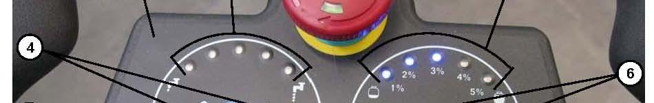
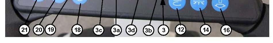
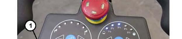
11 3.2 DESCRIPTION Control panel and controls (See Figure 3-1) 1. Control panel and controls 2. Emergency stop button 3. Display: indicating: 3a. "READY": machine ready, or "SIT DOWN": sit on seat 3b. Total hours of work done 3c. Battery charge status in % 3d. Battery charge status in graphic scale 4. Adjustment buttons (+ and -) for the flow rate of the detergent solution (or of the washing water) (*) 5. Light indication of the detergent solution level (or washing water) 6. Adjustment buttons (+ and -) of the percentage of detergent depending on the water flow of (optional) (*) 7. Light indication of the percentage of detergent depending on the water flow of (optional). 8. Turbo button, activation of the maximum cleaning solution level (or washing water) and detergent, for 30 seconds. 9. Light indication for the 30 seconds. 10. Button for adjusting the maximum speed of the machine (*) 11. Light indication of the instantaneous speed of the machine 12. Button for activating the lowering and the rotation of the disc brush (or cylindrical brushes) 13. Light indication of the disc brush (or cylindrical brushes) enabled; the light indication flashes when moving from enabled to disabled and vice versa 14. Button for activating ating the lowering of the squeegee and the water recovery er vacuum. 15. Light indication of squeegee and vacuum activated; the light indication flashes when moving from disabled to enabled and vice versa 16. Activation button simultaneously both for the squeegee and vacuum and the disc brush (or cylindrical brushes). 17. Light indication of squeegee, vacuum and disc brush (or cylindrical brushes) activated; the light indication flashes when moving from disabled to enabled and vice versa 18. Reverse activation button. The speed is halved compared to moving forward. For the reverse activation time, an audible warning signal is also activated 19. Light Indication of reverse enabled 20. Button which activates the acoustic signal. 21. Disc brush release button (*): When the machine is switched on using the key, these adjustments are positioned on previously set values.


12
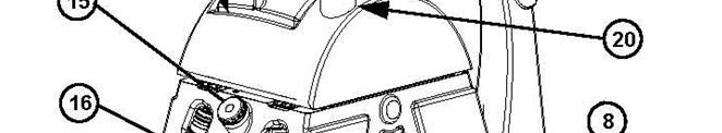
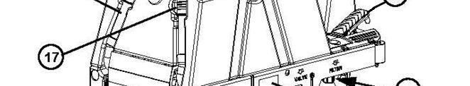
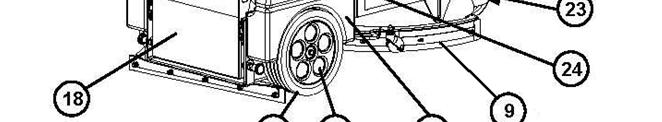
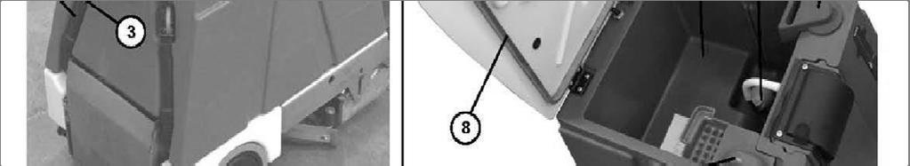
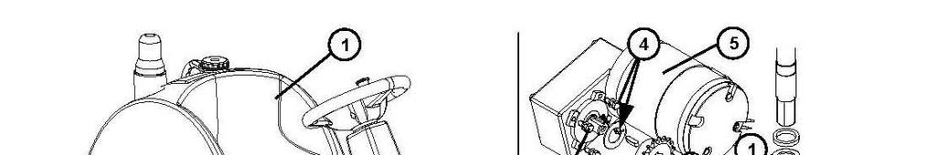
13 External views (See Figure 3-2 and Figure 3-3) 1. Steering wheel 2. Ignition key: 0: off I: on 3. Start pedal and acceleration 4. Level indicator of the detergent solution (or washing water) 5. Front Wheel, traction and steering 6. Rear wheels 7. Disc brush 8. Throttle Pedal 9. Squeegee 10a. Tank for the detergent solution (or washing water), 10a. Tank for the detergent solution (or washing water), 10b. Recovery water tank 11. Tank cover 12. Operator's seat 13. Detergent tank with handle (optional) 14 Cap for detergent tank 14. Cap for detergent tank. 15. Cap for the detergent solution (or washing water) 16. Recovery water drain hose 17. Detergent solution drain hose (or washing water) 18. Battery holder drum 19 Fl hi li ht ( ti l) 19. Flashing light (optional) 20. Drink holder container (only usable if the flashing light is not installed) 21. Storage container (only usable if the detergent tank is not installed) 22. Protective panel of the electric-electronic compartment 23. Filter for the detergent solution (or washing water) 24. Registration plate / technical data. CE mark 25. Handle for lifting the tanks cover 26. Heel unit 27. Cover for rear wheel 28. Mudguard for rear wheel 29. Emergency and parking brake

14 Figure 3-2
15

16
17
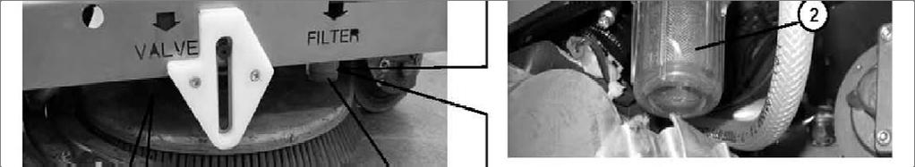
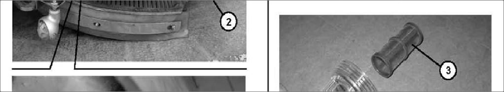
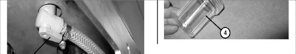
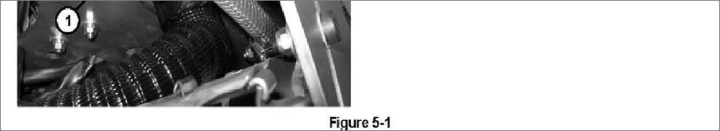
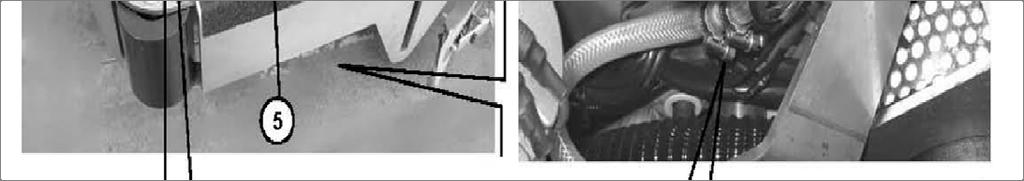
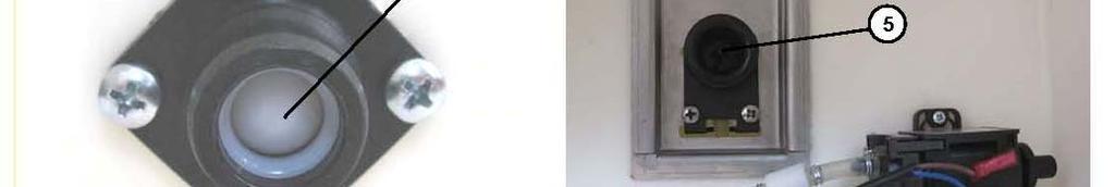
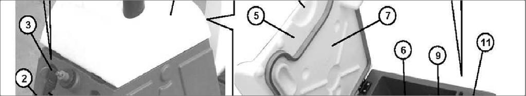
18 CHAPTER 5 5. CLEANING SOLUTION SUPPLY SYSTEM The significant maintenance/replacement procedures relating to the detergent solution (or washing water) supply system are described in this chapter. In addition Troubleshooting is described in the final section. 5.1 TANK CLEANING AND DETERGENT SOLUTION (OR WASHING WATER) SYSTEM 1. Operating as described in the User and Maintenance Manual, drain the detergent solution (or washing water) tank. 2. Operating as described in the User and Maintenance Manual, run the machine until the detergent solution (or washing water) in the machine runs out. 3. Cleaning the solution filter (or washing water). See 5.2 for the specific procedure. 5.2 CLEANING FILTER FOR THE DETERGENT SOLUTION (OR WASHING WATER) 1. Make sure that the machine cannot move independently. 2. Operating on the machine's controls as provided for in the User and Maintenance Manual, lower the squeegee and the disc brush (or cylindrical brushes), then turn the ignition key to " 0" and take it out. 3. Locate the solution shut off valve on the right side of the machine and turn off (1, Figure 5-1) for the water flow/detergent solution. 4. Unscrew and remove the transparent cover with filter (2). 5. Remove filter (3) from transparent cover (4). 6. Clean filter (3) and transparent cover (4). 7. Replace the filter (3) in its housing of the transparent cover (4). 8. Screw the transparent cover with filter in place (2) Turn on the solution valve (1). 10. Turn the ignition key to the "I" and wait for the squeegee and the disc brush (or cylindrical brushes), and then turn the ignition key to " 0" and take it out.
19

20 5.3 DISASSEMBLY/ASSEMBLY DETERGENT SOLUTION (OR WASHING WATER) SUPPLY SYSTEM FILTER UNIT Removal 1. If available, place the machine on a lifting platform, then lift. Otherwise, place the machine on a level floor. 2. Operating on the machine's controls as provided for in the User and Maintenance Manual, lower the squeegee and the disc brush, then turn the ignition key to 0 (off) and take it out. 3. Operating on the right side of the machine, close the tap (1, Figure 5-2) for the detergent solution flow (or washing water). 4. Loosen the straps (2) and disconnect the pipes (3) from the filter unit (4). 5. Unscrew the screws with nut (5). 6. Remove the filter unit (4). 7. If necessary break the filter unit (4). Assembly 8. Assemble, by reversing the sequence of operations performed for disassembly Figure 5-2
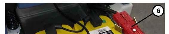
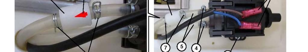
21 5.4 REMOVAL/INSTALLATION OF THE SOLUTION PUMP Removal 1. If available, place the machine on a lifting platform, then lift. Otherwise, place the machine on a level floor. 2. Operating on the machine's controls as provided for in the User and Maintenance Manual, lower the squeegee and the disc brush (or cylindrical brushes), then turn the ignition key to "0" and take it out. 1. Remove the battery holder drum and disconnect the battery connector (6, Figure 3-4) (For the procedure User and Maintenance Manual). 2. Operating on the right side of the machine, close the tap (1, Figure 5-3) ) for the detergent solution flow (or washing water). 3. Operating on the front left side of the machine, loosen the straps (2) and disconnect the pipes (3) from the pump (4). 4. Remove the non-slip mat (5) by releasing the adhesive surface. 5. Unscrew the screws with nut (6). 6. Disconnect the electrical connector (7) from the pump. 9. Remove the pump (4). Assembly 10. Assemble, by reversing the sequence of operations performed for disassembly.
22
. 2.")

 unscrew the nut")
. 6. Clean the nozzle (3) and the filter (5).")
 and the seal (4), then screw the ring nut")
23 5.5 CLEANING NOZZLE AND FILTER FOR DISPENSING CLEANING SOLUTION TO DISC BRUSH 1. Remove the brush (For the procedure, see the User and Maintenance Manual). 2. If available, place the machine on a lifting platform, then lift. Otherwise, place the machine on a level floor. 3. Turn the ignition key (2, Figure 3-2) to position "0". 4. Locate the nozzle in the center of the brush hub (1, Figure 5-4) unscrew the nut (2) and retrieve the nozzle (3) and the seal (4). 5. Remove the filter from the housing (5). 6. Clean the nozzle (3) and the filter (5). 7. Correctly reposition the filter (5) in its housing. 8. Position the nozzle in the housing (3) and the seal (4), then screw the ring nut (2). 9. If positioned, remove the machine from the lifting platform. 10. Reinstall the brush (For the procedure, see the User and Maintenance Manual).
 and remove key. 3.")
 in its housing. 7. Position the nozzle in the housing (2) and the seal (3), then screw the ring nut (1). 8.")
24 5.6 CLEANING THE SPRAY NOZZLE AND FILTER ON CYLINDRICAL BRUSH DECKS 1. If available, place the machine on a lifting platform, then lift. Otherwise, place the machine on a level floor. 2. Operating on the machine's controls as provided for in the User and Maintenance Manual, lower the cylindrical brush deck, then turn the ignition key to 0" (off) and remove key. 3. Locate the spray nozzle in the front of the cylindrical brush head head, unscrew the ring nut (1, Figure 5-5) and recover the nozzle (2) and the seal (3). 4. Remove the filter from the housing (4). 5. Clean the nozzle (2) and the filter (4). 6. Correctly reposition the filter (4) in its housing. 7. Position the nozzle in the housing (2) and the seal (3), then screw the ring nut (1). 8. Turn the ignition key to the "I (on) and wait for the lifting of the cylindrical brushes, and then turn the ignition key to 0 and take it out.
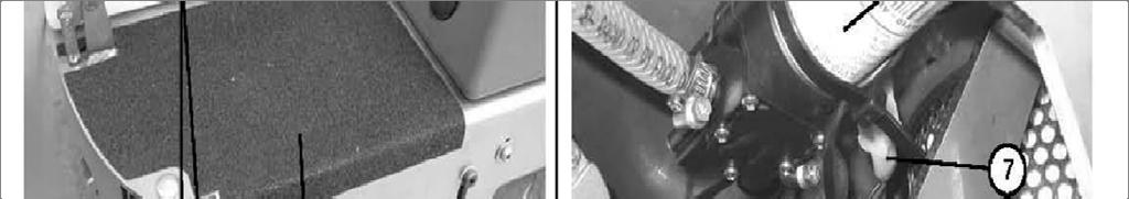
25 5.7 TROUBLESHOOTING REDUCED OR NO CLEANING SOLUTION REACHING THE BRUSH(S) Possible causes can be 1. Filters for he detergent solution clogged/dirty (clean the filters) 2. Solution valve turned off. (open the valve) 3. Pump broken or electrical connection interrupted (replace the pump/restore the electrical connection) 4. Debris in the detergent solution/water tank that is obstructing the exit hole (clean the tank) 5. Debris in the spray nozzle or filter. (clean the nozzle and filter) CHAPTER 6 CHEMICAL MIXING SYSTEM (OPTIONAL) This chapter describes the significant maintenance/replacement procedures related to the chemical and washing water mixing system. The last paragraph also describes Troubleshooting. 6.1 CLEANING THE CHEMICAL TANK AND THE CORRESPONDING VALVE 1. Make sure that the machine cannot move independently, and then turn the ignition key to 0" (off) and remove the key. 2. Remove the detergent tank from the machine (1, Figure 6-1), by gripping its handle (2) and lifting. 3. Unscrew the cap (3) and drain the washing detergent from the tank, in the area for disposing of the washing detergent. 4. Wash the washing detergent tank (1) and the corresponding one-way valve (4). 5. Operating in the tank compartment (1), lift the valve with pusher (5) by inserting a plate under the edge (6) of the support, then wash it and wipe it clean. Reposition it in the housing. 6. Screw on the cap (3) and place the tank (1) in its housing in the machine.


26
27 6.2 DISASSEMBLY/ASSEMBLY CHEMICAL PUMP AND ONE-WAY VALVE 1. Make sure that the machine cannot move independently, and then turn the ignition key to 0 (off) and remove the key. 2. Remove the detergent tank from the machine (1, Figure 6-2), by gripping its handle (2) and lifting. 3. Remove the battery holder drum and disconnect the battery connector (6, Figure 3-4) (For the procedure, see the User and Maintenance Manual). 4. Operating on the tank housing compartment (1, Figure 6-2), ) disconnect the electrical connections (2) from the pump (3). 5. Release the retaining straps (4) and disconnect the pipes (5) from the pump. 6. Unscrew the screws (6) and remove the pump (3). 7. If necessary, remove the straps (7) and disconnect the unidirectional valve (8) from the corresponding Assembly 8. Assemble, by reversing the sequence of operations performed for disassembly, with the following instruction: reinstall the one-way valve (8) with the arrow (9) facing the direction of the detergent flow (as in Figure 6-2).

28
29 6.3 TROUBLESHOOTING LITTLE OR NO DETERGENT MIXING WITH THE CLEANING SOLUTION Possible causes can be: 1. Percentage of detergent set too low (check/change the percentage by operating as described d in the User and Maintenance Manual) 2. Detergent tank valve dirty (clean it) 3. Pump broken or electrical connection interrupted (replace the pump/restore the electrical connection) 4. Debris in the detergent hose, obstructing the passage (clean the hose) 5. The detergent adjustment button is inefficient (check the led on the button is on, otherwise change electronic board functions) 6. The electronic board functions are not working (replace it) WATER IS ENTERING THE DETERGENT TANK Possible causes can be: 1. The one-way valve for the detergent tank is broken (replace it)

. 2.")
. 4.")
30 CHAPTER 7 BRUSH SYSTEM The significant maintenance/replacement procedures relating to the Brush system are described in this chapter. In addition troubleshooting is described in the final section. 7.1 CLEANING DISC BRUSHES CAUTION! The use of work gloves is recommended when cleaning the disc brush, due to the possible presence of sharp debris. 1. Remove the disc brush (See the procedure in the User and Maintenance Manual ). 2. Wash and clean the disc brush (1, Figure 7-1) of dirt and debris; use water and detergent solution. 3. Fit the disc brush (See the procedure in the User and Maintenance Manual ). 4. The disc brush must be replaced due to excessive wear, when in the condition of brush lowered, the side pins (2, Figure 7-1) rest on the lower ends (3) of the slots.

. 2.")
 of the cylindrical brushes. 4.")
. 5.")
31 7.1 CLEANING THE CYLINDRICAL BRUSHES CAUTION! The use of work gloves is recommended when cleaning the cylindrical brushes, due to the possible presence of sharp debris. 1. Remove the cylindrical brushes (See the procedure in the User and Maintenance Manual). 2. Wash and clean the cylindrical brushes of dirt and debris, use water and detergent solution. 3. Also wash and clean the housings (1, Figure 7-2) of the cylindrical brushes. 4. Check that the hubs (2) driving the cylindrical brushes are free of debris dirt or intertwined objects (cords, etc.). 5. Reassemble the cylindrical brushes (See the procedure in the User and Maintenance Manual). 6. The cylindrical brushes must be replaced due to excessive wear, when in the condition of brushes lowered, the side pins (1, Figure 7-3) rest on the lower ends (2) of the slots.

 (For the procedure, see the User and Maintenance Manual). 6.")

32 7.2 DISASSEMBLY/ASSEMBLY OF THE DISC BRUSH HEAD Removal 1. Remove the brush (For the procedure, see the User and Maintenance Manual). 2. If available, place the machine on a lifting platform, then lift it. 3. Otherwise, place the machine on a level floor. 4. Operating on the control panel lower brush holder head, and then place the ignition key (2, Figure 3-2) in the position "0". 5. Remove the battery holder drum and disconnect the battery connector (6, Figure 3-4) (For the procedure, see the User and Maintenance Manual). 6. Operating on both sides of the machine, unscrew the (1, Figure 7-4). 7. Unscrew the screw with nut (2, Figure 7-5) securing the actuator to the head. 8. Disconnect the electrical connector from the disc brush motor. 9. Remove the disc brush holder head. Assembly 10. Assemble, by reversing the sequence of operations performed for disassembly.
33 7.3 DISK BRUSH MOTOR TEST WARNING! This procedure must be performed by qualified personnel. 1. Remove the disc brush (1, Figure 7-6), operating as indicated in the User and Maintenance Manual. 2. Turn the ignition key to "0". 3. Place a wooden block (2, Figure 7-6) 6-7 cm high under the rear wheels of the machine. Also apply wedges (3, Figure 7-6) on both of the rear wheels, to securely lock the machine. 4. Apply two suitable wooden shims (4, Figure 7-6) under the front chassis of the machine, high enough to also lift the front wheel by 6-7 cm. WARNING! Keep the wooden shims (4, Figure 7-6) at an appropriate distance from the disc brush hub. Make sure that all the wooden shims are completely stable to be able to mount the machine and operate the controls. 5. Open the cover (5, Figure 7-6) and remove the panel (6) by lifting it up. Lower the cover back down (5). 6. Apply the current clamp (7, Figure 7-6) to one of the power leads (8) for the disc brush motor. 7. Cautiously sit on the seat of the machine. WARNING! Do not touch any electrical components that are not protected by the panel (6, Figure 7-6), as removed! 8. Turn the ignition key to "I" and wait for the word "READY" on the display. 9. Operating on the machine's controls as indicated in the User and Maintenance Manual, lower and rotate the disc brush, and then check on current clamp that the absorption of the motor is approximately 5 amps at 24 volts. 10. Stop the rotation of the brush. 11. Turn the ignition key to the "0". 12. Get off the machine and remove the current clamp. 13. If the absorption is greater, perform the steps below in sequence to locate and eliminate the cause of the anomalous absorption: check that there is no debris or dirt (cords, cables, etc.) on the brush fastening hub. check the carbons of the electric motor (see procedure in the specific paragraph) if necessary, disassemble the motor (See procedure in the specific paragraph) then check the state of its parts. In the case where the operations described above do not lead to a proper absorption of the motor, it will need replacing (see procedure in the specific paragraph). 14. Reverse steps 1 to 5.
34
. 3. Remove the disc brush drive belt (See the procedure in the specific paragraph). 4.")
 and remove the motor (7) from the disc brush. Assembly 8.")
35 7.4 CHECK AND REPLACEMENT OF DISC BRUSH MOTOR CARBONS Removal 1. Remove the disc brush, operating as provided for in the User and Maintenance Manual). 2. Remove the disc brush holder head (See procedure in the specific paragraph). 3. Remove the disc brush drive belt (See the procedure in the specific paragraph). 4. Unscrew the screws (1, Figure 7-9) and remove the brush holder hub (2). 5. Disconnect the tensioning spring (2, Figure 7-10) from the stud (3). 6. Unscrew the screw (4) and remove the tensioner (5). 7. Unscrew the screws (6, Figure 7-10) and remove the motor (7) from the disc brush. Assembly 8. Assemble, by reversing the sequence of operations performed for disassembly, with the following instruction: place the engine orientated with the red element (8, Figure 7-10), oriented toward the forks (9), as shown in the figure.
36 7.4 CHECK AND REPLACEMENT OF THE CARBON BRUSHES FOR THE DISK BRUSH MOTOR 1. Remove the disc brush holder head (see procedure in the specific paragraph). 2. Externally cleaning the motor or dirt and dust, in the area of the carbon supports (1, Figure 7-7). 3. Remove the four carbon supports (1) after having disengaged the retainers (2) and (3). If necessary, disconnect the electrical connections (4). 4. Check the state of wear of the four carbons (5); the carbons are worn when sufficient contact with the armature of the motor is not provided because of their consumption, the non-integrity of the contact surfaces, broken thrust spring, etc. The minimum length of the carbons (5) is 15 mm, which, when reached must be replaced. 5. If necessary, disconnect the connections (6) and remove the carbons complete with support (1) to replace them. The carbons should be replaced all together. 6. For the reassembly, reverse the sequence of operations performed for disassembly, with the following caution: when fixing the terminals (6) pay particular attention to their isolation from the surrounding chassis parts.
. 3.")
. Assembly 4. By means of a clamp disconnect the end (5) of the tensioning spring (6) from the stud (7). 5.")
37 7.5 DISASSEMBLY/ASSEMBLY DISC BRUSH DRIVE BELT Removal 1. Remove the disc brush (See the procedure in the User and Maintenance Manual). 2. Remove the disc brush holder head (See procedure in the specific paragraph). 3. Operating on the disc brush holder head, manually rotate the brush holder hub (1, Figure 7-8) progressively the lifting belt (2) until it disengages from the pulleys (3) and (4) and from the brush holder hub (1). Assembly 4. By means of a clamp disconnect the end (5) of the tensioning spring (6) from the stud (7). 5. Insert the belt in the housing (2) making it engage the pulleys (3) and (4) and to the brush holder hub (1). 6. By means of a clamp on the end (5) pull the tensioning spring (6) and make it engage with the stud (7). 7. Check the efficiency of the tensioner, and then manually turn the brush holder hub a few turns (1) and check the correct belt drive (2). 8. Assemble the disc brush holder head (See procedure in the specific paragraph). 9. Fit the disc brush (See procedure in the User and Maintenance Manual).

 (For the procedure, see the User and Maintenance Manual). 5.")
. 7. Unscrew the screws (4. Figure 7-12) securing the support (5) of the electrical components. 8. Carefully move the support forward slightly (5, Figure 7-12). ) 9.")
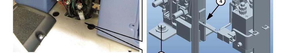
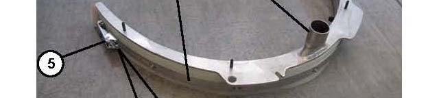
38 7.6 DISASSEMBLY/ASSEMBLY DISC BRUSH LIFT ACTUATOR Disassembly 1. Remove the disc brush (7, Figure 3-2), operating as indicated in the User and Maintenance Manual. 2. If available, place the machine on a lifting platform; otherwise, place the machine on a level floor. Make sure that the machine cannot move independently. 3. Operating on the machine's controls as provided for in the User and Maintenance Manual, lower the disc brushes, then turn the ignition key to "0" and take it out. 4. Remove the battery holder drum and disconnect the battery connector (6, Figure 3-4) (For the procedure, see the User and Maintenance Manual). 5. Operating above the brush head (1, Figure 7-11) unscrew the nut (2) 6. and remove the lower retaining screw (3) of the actuator to the brush head. 6. Open the tank covers (11, Figure 3-2) and remove the panel (22) by lifting it up. Lower the cover back down (11). 7. Unscrew the screws (4. Figure 7-12) securing the support (5) of the electrical components. 8. Carefully move the support forward slightly (5, Figure 7-12). ) 9. Remove the split pin (6, Figure 7-12) and pull the upper retaining pin (7) for the actuator (8). 10. Remove the actuator (8, Figure 7-12) after having disconnected the electrical connection. Assembly 11. Assemble, by reversing the sequence of operations performed for disassembly.


39
40 7.7 TROUBLESHOOTING THE BRUSH DOES NOT ROTATE Possible causes can be: 1. Large debris or cords around the brush or between the brush and its attachment flange (remove the brush and remove debris or cords) 2. Blown fuse for motor (replace/check for cause of overload) 3. Electric motor with the worn carbons (replace the electric motor carbons) 4. Faulty brush relay (replace if defective) 5. Electric motor in the event of a failure (repair or replace the electric motor) 6. Electronic board functions damaged d (replace it if defective) 7. Damaged wiring (repair it) THE BRUSH DOES NOT REACH THE "RAISED" or "LOWERED" POSITION. Possible causes can be: 1. Electric actuator to raise/lower brush head, broken (replace it) 2. Actuator wiring interrupted (check the wiring)
41 CHAPTER 8 RECOVERY SYSTEM Maintenance/replacement procedures relating to the water recovery system are described in this chapter. In addition Troubleshooting is described in the final section. 8.1 CLEANING THE RECOVERY WATER TANK AND GRATES 1. Bring the machine to the area responsible for disposing of the recovery water, in compliance with the applicable emission standards. 2. Disengage the hose (1, Figure 8-1) from the housing and lift it over the upper lip of the tank, until its area (2) is free of water, and then keeping it in this position, unscrew the cap (3). 3. Manually bend the hose in the area (2) to obtain a water-tight bend (13), and then keeping it bent lower it into the drain area. 4. Gradually (to avoid unwanted splashing) release the bend (13) by draining the dirty water from the tank in the drain area. 5. By means of the grip (4) lift the tank covers (5). 6. Remove the grate (10) by lifting it, then get rid of any debris and wash it. 7. Remove the grate (11) by lifting it, then get rid of any debris and wash it. Particularly clean the lower hole (12). 8. Wash the recovery water tank (6); also wash the lower side (7) of the cover and the perimeter seal (8). Check that the perimeter seal (8) is undamaged: if damaged it can compromise the proper functioning of the dirty water vacuum. If necessary, remove the seal (8) disengaging it from the housing, and then replace it. CAUTION! Do not damage the float (9). NOTE: The float must be placed in the lowest part in the tank. 9. Drain all the washing water from the hose (1), then screw on the cap (3) and engage the hose (1) into the machine's housing. 10. Reinstall the grates in the housing (10) and (11). 11. Close the tank cover (5).
42
. 3. Open the tank covers (11, Figure 3-2) and remove the panel (22) by lifting it up. Lower the cover back down (11). 4.")
, as removed! 6.")
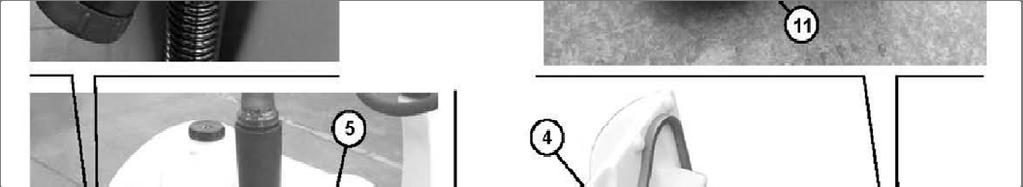
43 8.2 CHECKING THE AMPERAGE OF THE VACUUM MOTOR WARNING! This procedure must be performed by qualified personnel. 1. Install a new vacuum filter on the machine (see procedure in specific paragraph). 2. Disconnect the vacuum hose from the squeegee's attachment t (10, Figure 8-6). 3. Open the tank covers (11, Figure 3-2) and remove the panel (22) by lifting it up. Lower the cover back down (11). 4. Apply the current clamp (1, Figure 8-2) to one of the power leads (2) for the vacuum motor. 5. Sit on the seat of the machine. the WARNING! Do not touch any electrical components that are not protected by panel (22, Figure 3-2), as removed! 6. Operating on the machine's controls as indicated in the User and Maintenance Manual, lower the squeegee and the disc brush, by activating the vacuum and then check on current clamp that the absorption of the vacuum motor is approximately 20 amps at 24 volts. 7. Lift the squeegee and the disc brush. 8. Turn the ignition key to the "0". 9. Remove the current clamp. 10. If the absorption is greater, perform the steps below in sequence to locate and eliminate the cause of the anomalous absorption: check that the motor is properly positioned and that there is no debris or dirt on the air inlet of the aspirator area. check the charcoals of the electric motor (see procedure in the specific paragraph) if necessary, disassemble the motor (See procedure in the specific paragraph) then check the state of its parts. In the case where the operations described above do not lead to a proper absorption of the motor, it will need replacing (see procedure in the specific paragraph). 11. Open the cover (11, Figure 3-2) and put the panel in the housing (22). Lower the cover back down (11).
 from the vacuum motor (2), by disengaging the inner retainers. 3. Unscrew the screws (3). 4. Disconnect the electrical connections (4). 5. Remove the carbons (5). 6.")
44 8.3 CHECKING AND REPLACEMENT OF VACUUM MOTOR CARBON BRUSHES 1. Remove the vacuum motor (See the procedure in the specific paragraph). 2. Remove the cover (1, Figure 8-3) from the vacuum motor (2), by disengaging the inner retainers. 3. Unscrew the screws (3). 4. Disconnect the electrical connections (4). 5. Remove the carbons (5). 6. Check the state of wear of the carbons; which ones are worn when sufficient contact with the armature of the motor is not provided because of their consumption, the non-integrity of the contact surfaces, broken thrust spring, etc. 7. If necessary, replace the carbons. The carbons should be replaced together. 8. For the reassembly, reverse the sequence of operations performed for disassembly.
45 8.4 DISASSEMBLY/ASSEMBLY OF THE SUCTION MOTOR Removal 1. If available, place the machine on a lifting platform; otherwise, place the machine on a level floor. Make sure that the machine cannot move independently. 2. Operating on the machine's controls as provided for in the User and Maintenance Manual, lower the brush and the squeegee, then turn the ignition key to "0" and take it out. 3. Remove the battery holder drum and disconnect the battery connector (6, Figure 3-4) (For the procedure, see the User and Maintenance Manual). 4. Operating on the left side of the machine, unscrew the screws (1, Figure 8-4). 5. Remove the support unit with the vacuum motor and filter (2), after you have disconnected the electrical connector (3) of the vacuum motor. 6. Remove the sound insulating seal from the bench (4). 7. Remove the vacuum motor (5). Assembly 8. Reassemble, by reversing the sequence of operations performed for disassembly.
46
. 2. Wash and clean the squeegee(1, Figure 8-5); in particular clean dirt and debris from the compartments (2) and the hole (3).")
47 8.5 CLEANING/CHECK THE SQUEEGEE AND REPLACEMENT OF THE SQUEEGEE BLADES Cleaning CAUTION! The use of work gloves is recommended when cleaning the squeegee, due to the possible presence of sharp debris. 1. Remove the squeegee (See the procedure in the specific paragraph). 2. Wash and clean the squeegee(1, Figure 8-5); in particular clean dirt and debris from the compartments (2) and the hole (3). Check that the front blade (4) and the rear blade (5) are undamaged and have no cuts or tears, otherwise replace them (see the procedure below). 3. Refit the squeegee (See the procedure in the specific paragraph).
48 8.5 Inspection and Replacement of Squeegee Blades Cont. 4. Remove and clean the squeegee, operating as described above. 5. Check that the front blade (1, Figure 8-6) and the rear blade (2) are undamaged and have no cuts or tears, otherwise replace them, as described on the following page. Also check that the front edge (3) of the rear blade (2) is not worn; otherwise turn the blade over, putting one of the other three corners in its place, if it is still undamaged. Even if the other three corners are worn, replace the blade, by operating as described below: Replace (or invert) the rear blade (2) after having disengaged the retainer (4), released the eccentric (5), and removed the retainer strip (7) disengaging them from the pins with nut (6); finally put the blade back, operating in the reverse order of removal. Replace the front blade (1) after having unscrewing the nuts (8) and removed the retainer strip (9), and finally put the blade back by operating in reverse order of removal. 6. Reinstall the squeegee, as described in the specific paragraph. 7. If necessary, adjust the height of the squeegee, operating as described in the following pages.


49


. 9.")
50 8.5 Squeegee Height Adjustment Note: Adjusting the height of the squeegee is required when the machine does not dry properly, leaving streaks of water in the central region, or on the ends. 8. To adjust the height of the squeegee, loosen the nuts (1, Figure 8-7) and adjust the height of the right and left wheel (2). 9. At the end of the adjustment, tighten the nuts.
51 8.6 DISASSEMBLY/ASSEMBLY AND CLEANING/REPLACING THE SUCTION FILTER Removal 1. Remove the vacuum motor (See the procedure in the specific paragraph). 2. Remove the vacuum filter (1, Figure 8-8) by detaching it from the other parts of the unit. 3. Clean the vacuum filter with brush and compressed air (max. 5 Bar). If the filter is damaged replace it. WARNING! Adequately protecting parts of the body (eyes, hair, hands, etc.) when performing cleaning Operations using compressed air guns. Assembly 4. Reassemble, by reversing the sequence of operations performed for disassembly.

 (For the procedure, see the User and Maintenance Manual). 4.")
 (to facilitate the subsequent removal of the")
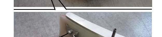
52 8.7 DISASSEMBLY/ASSEMBLY - SQUEEGEE ACTUATOR Removal 1. If available, place the machine on a lifting platform; otherwise, place the machine on a level floor. Make sure that the machine cannot move independently. 2. Operating on the machine's controls as provided for in the User and Maintenance Manual, lower the squeegee, then turn the ignition key to "0" and take it out. 3. Remove the battery holder drum and disconnect the battery connector (6, Figure 3-4) (For the procedure, see the User and Maintenance Manual). 4. Operating on the squeegee (1, Figure 8-9) unscrew the nut (2) and remove the screw (3) with a retaining washer, lower squeegee actuator rod (4). 5. Operating on the machine's controls as instructed in the User and Maintenance Manual, operate the squeegee's lift control, so as to raise the rod (4) (to facilitate the subsequent removal of the actuator). Turn the ignition key to the "0" and take it out. 6. Remove the batteries from the machine (See procedure in the specific paragraph). 6. By operating at the top front side of the battery compartment, remove the split pin (5) and pull the upper pin (6) securing the actuator (7). 8. Disconnect the electrical connector (8) of the squeegee'ss actuator. 9. Remove the actuator (7) from the squeegee. Assembly 10. Assemble, by reversing the sequence of operations performed for disassembly.
53 8.8 TROUBLE SHOOTING THE ELECTRIC SUCTION MOTOR DOES NOT TURN ON Possible causes can be: 1. Electric vacuum motor with worn carbons (replace the electric motor carbons) 2. Electric vacuum motor failure (check the motor's absorption) 3. Electronic board functions damaged (replace it) 4. Recovery water tank, full and float activated (empty the recovery water tank) THE SUCTION OF THE DIRTY WATER IS INSUFFICIENT OR NOT TAKING PLACE Possible causes can be: 1. Cover for the tanks (11, Figure 3-2) incorrectly positioned (position it correctly) 2. Seal of the cover for the tanks, not efficient (eliminate the causes) 3. Squeegee or vacuum hose clogged or damaged (clean or repair/replace them) 4. Squeegee blades flaps torn or worn (replace them) THE SQUEEGEE LEAVES MARKS OR DOES NOT COLLECT WATER Possible causes can be: 1. Debris under the edge of the squeegee blades (remove it) 2. Squeegee blades flaps torn or worn (replace them) 3. Squeegee height not adjusted properly (adjust it 4. The closure tap for the recovery water drain hose (16, Figure 3-3) is open (close it) THE SQUEEGEE CANNOT BE LIFTED/LOWERED THE SQUEEGEE CANNOT BE LIFTED/LOWERED Possible causes can be: 1. Actuator failure (repair it/replace it) 2. Electronic board functions damaged (replace it)
54 CHAPTER 9 DRIVE SYSTEM The significant maintenance/replacement procedures relating to the Drive system are described in this chapter. In addition Troubleshooting is described in the final section. 9.1 PROCEDURE TO CHANGE THE MAXIMUM DRIVE SPEED OF THE MACHINE WARNING! This procedure can only be performed by the person responsible for the machine, who must adjust the maximum speed of the machine, taking into account the experience of the operator to whom the machine is entrusted, for the washing/drying activity. The operator is absolutely prohibited from varying the maximum speed of the machine. 1. Turn the ignition key to "I" while holding down the button (1, Figure 9-1) and wait for the display (2) the setting (3), and then release the button (1). The value (4) indicates the maximum pre-set speed on the machine. The maximum speed can be set from a minimum value of 1/5 to a maximum value of 5/5. 2. Press the button (1) several times until the maximum speed value desired is set on area (4) of the display. 3. Wait for the machine to reset; the new maximum speed is set.


55
 to both rear wheels, to securely lock the machine. 4.")
 and (6). 7. Remove the front wheel assembly (7) by releasing the pinion (8) from the chain (9). Assembly 8.")
56 9.2 DISASSEMBLY/ASSEMBLY OF THE DRIVE WHEEL Removal 1. If available, place the machine on a lifting platform; otherwise, place the machine on a level floor. Make sure that t the machine cannot move independently. d 2. Turn the ignition key to the "0" and take it out. 3. Apply wedges (1, Figure 9-2) to both rear wheels, to securely lock the machine. 4. Apply two suitable wooden shims (2) under the front frame of the machine, high enough to lift the front wheel by 5-6 cm (space necessary to then be able to remove the front wheel). 5. Unscrew the nut (3) and remove the retaining screw (4) for the front wheel. 6. Remove the spacers (5) and (6). 7. Remove the front wheel assembly (7) by releasing the pinion (8) from the chain (9). Assembly 8. Assemble, by reversing the sequence of operations performed for disassembly, with the following instruction: tighten the nut (3) of the screw (4) taking the wheel (7) thrust downwards; use a lever for this positioned between the top of the front wheel and the wheel support (11) compartment (10).
 and retrieve the washers. 3. Remove the pinion (2) and retrieve the lug (3). 4.")

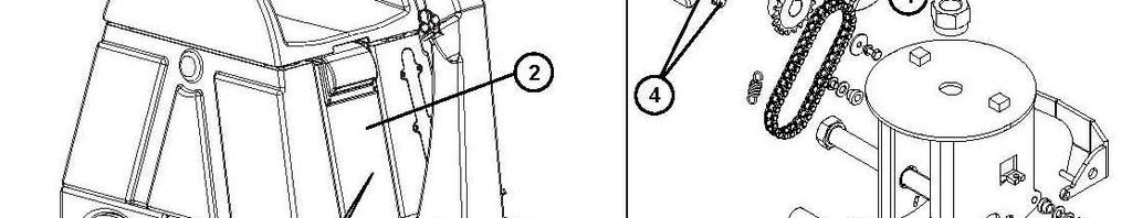
57 9.3 DISASSEMBLY/ASSEMBLY OF THE DRIVE CHAIN Removal 1. Remove the drive wheel (See the procedure in the specific paragraph). 2. Unscrew the screw (1, Figure 9-3.) and retrieve the washers. 3. Remove the pinion (2) and retrieve the lug (3). 4. Retrieve the self-lubricating bearing (4). 5. Retrieve e the chain (5). Assembly 6. Assemble, by reversing the sequence of operations performed for disassembly. CAUTION! Do not lubricate the chain (5), in order to prevent dust and debris from mixing with the lubricant.
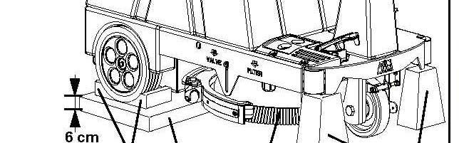
58 WARNING! This procedure must be performed by qualified personnel. 1. Turn the ignition iti key to the "0". 2. Apply wedges (1, Figure 9-4) to both rear wheels, to securely lock the machine. 3. Apply two suitable wooden shims (2) under the front chassis of the machine, high enough to also lift the front wheel by 6-7 cm. WARNING! Make sure that the wooden shims are completely stable to be able to mount the machine and operate the controls. 4. Open the cover (3) and remove the panel (4) by lifting it up. Lower the cover back down (3). 5. Apply the current clamp (5) to one of the power leads (6) for the drive motor. 6. Cautiously sit on the seat of the machine. WARNING! Do not touch any electrical components that are not protected by the panel (4), as removed! 7. Turn the ignition key to "I" and wait for the word "READY" on the display. WARNING! Pay attention to the rotation of the drive wheel (7) when performing the next steps. 8. Operate the start pedal (8) and reach the maximum speed (corresponding to the five lights on the control panel), then check on current clamp that the absorption of the drive motor is approximately 5 amps at 24 volts. 9. Stop the drive by releasing the accelerator pedal (8). 10. Turn the ignition key to the "0". 11. Get off the machine and remove the current clamp. 12. If the absorption is greater, perform the steps below in sequence to locate and eliminate the cause of the anomalous absorption: check that there is no debris or dirt (cords, cables, etc.) on the drive wheel hub or on the drive chain. check that the emergency and parking brake is not engaged and that it is not hindering the free rotation of the drive wheel. check the charcoals of the electric motor (see procedure in the specific paragraph) if necessary, disassemble the motor (See procedure in the specific paragraph) then check the state of its parts. In the case where the operations described above do not lead to a proper absorption of the motor, it will need replacing (see procedure in the specific paragraph). 13. Reverse steps 1 to 4.
59
60 9.5 DRIVE MOTOR CARBON BRUSHES Check 1. If you need to check all four carbons, remove the drive motor (See the procedure in the specific paragraph). 2. Release and remove the strap (1, Figure 9-5) of the drive motor (2) after you have cleaned externally the motor of dirt and dust. 3. For each of the four carbons, lift the retaining clip (3) and extract the carbons (4). 4. Check the state of wear of the four carbons; the carbons are worn when sufficient contact with the armature of the motor is not provided because of their consumption, the non-integrity of the contact surfaces, broken thrust spring, etc. Replacement 5. If necessary, remove the carbons to replace them, after having unscrewing the nuts (D) and freed the terminal lug (6). Restoring 6. Reassemble, by reversing the sequence of operations performed for disassembly.
61 9.6 DISASSEMBLY/ASSEMBLY OF THE DRIVE MOTOR Removal 1. Remove the drive wheel (See the procedure in the specific paragraph). 2. Remove the drive chain (See the procedure in the specific paragraph). 3. Remove the battery holder drum and disconnect the battery connector (6,Figure 3-4) (For the procedure, see the User and Maintenance Manual). 4. Open the cover (1, Figure 9-6) and remove the panel (2) by lifting it up. Lower the cover back down (1). 5. Disconnect the electrical connections (3) of the drive motor from the drive electronic board. 6. Unscrew the retaining screws (4) for the drive motor. 7. Remove the drive motor. (5). 8. Assemble, by reversing the sequence of operations performed for disassembly.

62
63 9.7 DISASSEMBLY AND ASSEMBLY OF DRIVE PEDAL Removal 1. Make sure that the machine cannot move independently, and then turn the ignition key to " 0" and take it out. 2. Remove the battery holder drum and disconnect the battery connector (6, Figure 3-4) (For the procedure, see the User and Maintenance Manual). 3. Unscrew the retaining screws (1, Figure 9-7) of the drive pedal (2). 4. Lift the drive pedal and disconnect its electrical connector (3). Assembly 5. Assemble, by reversing the sequence of operations performed for disassembly. 6. Adjust the drive pedal, operating according to the following procedure: CAUTION! In the context of the procedure described below, concerning the "adjustment of the drive pedal", make sure you do not vary any other setting of the machine. The machine settings are set by the manufacturer to optimize the functional characteristics of the machine itself, and are then saved before selling the machine. Changing the machine settings (except those covered by this manual) by anyone not authorized to do so, may be lead to the void the warrant of the machine and any other service contracts by the manufacturer.
64 9.7 ADJUSTING THE DRIVE PEDAL NOTE: Perform each operation within 10 seconds of the previous operation otherwise the board will be reset and you will have to resume operations from the start. 1. Turn on the machine. 2. During the start-up phase simultaneously press and hold down the (-) button of the water dosage and the (+) button of the detergent dosage the display shows "USER CHECK - PASSWORD:0" 3. Press the button (+) of the detergent dosage until you reach the number Press the button (TURBO) to confirm - the display shows "MONITOR: FUNCTIONS BOARD" 5. Press the button (+) of the water dosage 3 times - the display shows "SET TARGET: TRACTION BOARD" 6. Press the button (TURBO) to confirm - the display shows "T_SET: PAR 0 - RESET: 0" 7. Press the button (+) of the water dosage 8 times - the display shows "SINGLE ENDED" 8. Press the button "TURBO" TO CONFIRM - the display shows "CALIBRATION STOP POS = 1.2 V" 9. Press the button "TURBO" to confirm - the display shows "CALIBRATION - MAX POS = 1.2 V" 10. Fully press the drive pedal - the display shows "CALIBRATION - MAX POS = 3.0 V" 11. While holding down the drive pedal press the button "TURBO" - the display shows "T_SET: PAR 9 - REF.DB: 200 MV" 12. Release the drive pedal and wait for the machine to reset 13. Turn the machine off and on again
65
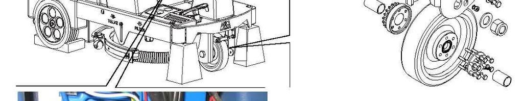
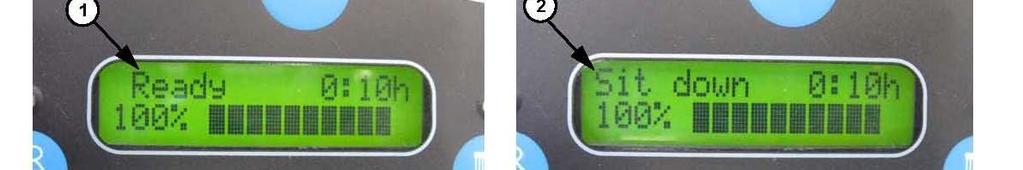
66 9.8 SEAT SAFETY SWITCH ADJUSTMENT Functionality check 1. Turn the ignition key to "I" without sitting on the seat of the machine and check that the control panel display shows "Sit down" (2, Figure 9-8). 2. Operating as indicated in the User and Maintenance Manual, check the correct operation of forward and backward motion of the machine. Check that the control panel display shows "Ready" (1). 3. Get off the machine and check that the control panel display shows "Sit down" (2). 4. If necessary, carry out the procedure described below (points from 5 to 8.) to adjust the micro-switch. Adjusting micro-switch 5. Open the cover (3) and remove the panel (4) by lifting it up. WARNING! Do not touch any electrical components that are not protected by the panel (4), as removed! 6. Loosen the nuts (5) and adjust the position of the micro-switch (6). Tighten the nuts (5). 7. Insert the panel in the housing (4), and then close the cover (3). 8. Check the functionality of the micro-switch by performing the previous points from 1 to 4. Replacing the micro-switch 9. Remove the battery holder drum and disconnect the battery connector (6, Figure 3-4) (For the procedure, see the User and Maintenance Manual). 10.Open the cover (3, Fig. 10-8) and remove the panel (4) by lifting it up. 11.Unscrew the nuts (5) and move the micro-switch (6). 12.Retrieve the micro-switch (6) after you have disconnected its electrical connections from the drive electronic board (7). 13. Assemble, by reversing the sequence of operations from step 9 to step 12, performed for disassembly. 14.Check the functionality of the micro-switch by performing the previous points from 1 to 4.


67
68 9.9 TROUBLESHOOTING THE MACHINE IS MOVING SLOWLY OR NOT MOVING Possible Causes can be: 1. Large debris or cords around the drive wheel or the drive chain (remove any debris/cords) 2. Excessive slope of floor (do not use traction to go over slopes higher than that provided for) 3. The drive pedal (15) is poorly adjusted or broken (adjust or replace it) 4. The voltage of the batteries has dropped excessively (charge the batteries) 5. The drive safety micro-switch is faulty (repair/replace it) 6. The parking brake does not turn off (see the chapter on the Parking brake system) 7. The drive electronic board is not working (replace it) 8. The electronic board functions are faulty (see the chapter on the Electrical System) 9. The drive motor has worn carbons (replace them) 10. The drive motor is faulty (replace it).
 in the corresponding tanks, empty them (See the procedure on the User and Maintenance Manual). 2.")
69 10. Miscellaneous Systems The significant maintenance/replacement procedures relating to Miscellaneous systems are described in this chapter 10.1 TIGHTENING SCREWS AND NUTS CHECK 1. If there is recovery water and cleaning solution (or washing water) in the corresponding tanks, empty them (See the procedure on the User and Maintenance Manual). 2. If available, place the machine on a lifting platform; otherwise, place the machine on a level floor. Make sure that the machine cannot move independently. 3. Turn the ignition key to the "0" and take it out. 4. Remove the battery holder drum and disconnect the battery connector (6, Figure 3-4) )(For the procedure, see the User and Maintenance Manual). 5. Lift the cover (1, Figure 10-1), and remove the panel (2) by lifting it up. Continue with the check the following: of the tightening of the screws and nuts accessible of the correct position of the various fastening elements that there are no visible faults of various parts and components that there are no leaks of various liquids 6. Refit the various parts, by reversing the sequence of operations performed for disassembly.
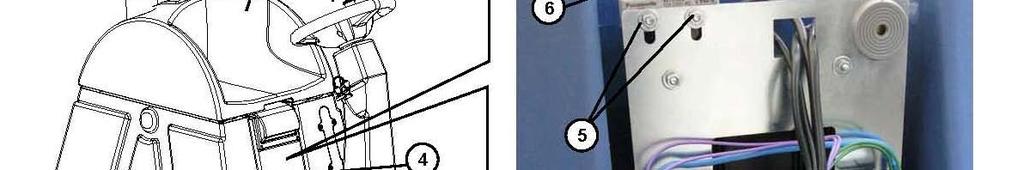
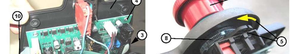
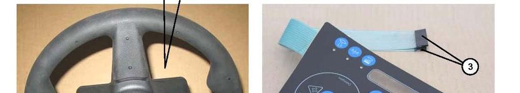
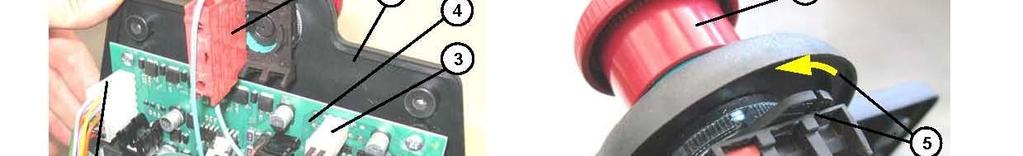
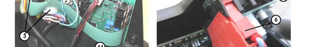
70 10.2 DISASSEMBLY/ASSEMBLY CONTROL PANEL KEYBOARD Removal 1. If available, place the machine on a lifting platform, otherwise, place the machine on a level floor. Make sure that the machine cannot move independently. 2. Turn the ignition key to the "0" and take it out. 3. Remove the battery holder drum and disconnect the battery connector (6, Figure 3-4) )(For the procedure, see the User and Maintenance Manual. 4. Operating under the steering wheel, unscrew the screws (1, Figure 10-2) 5. Carefully lift the keyboard assembly with a functions electronic board (2). 6. Disconnect the electrical connections (3) of the keyboard from the electronic board functions (4). 7. Turn the lever (5) and disconnect the electrical connector (6) from the emergency stop switch (7). 8. Turn the ring nut (8) and remove the emergency stop switch (7). 9. Carefully remove the keyboard (9) from support panel, disengaging its adhesive surface and Maintenance Manual. NOTE The removed keyboard is no longer usable. ASSEMBLY 10. Assemble, by reversing the sequence of operations performed for disassembly, with the following instruction: before you install the keyboard (9), remove any adhesive residue and clean the surface of the support panel and accession of the keyboard with solvent. before positioning the keyboard assembly in the housing with an electronic board functions (2), check that the perimeter seal (10) is efficiently and correctly positioned in the housing.
71
, but without separating the function board (1, Figure")
 from the electrical connector (4) of the emergency stop switch.")
 from the conical engagement with a key, exerting force on the point (7)")
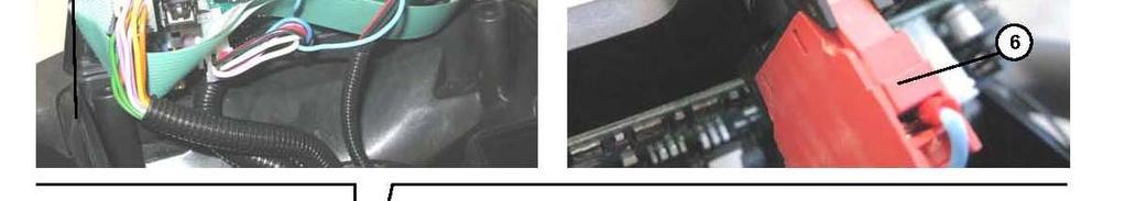
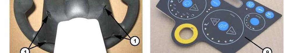
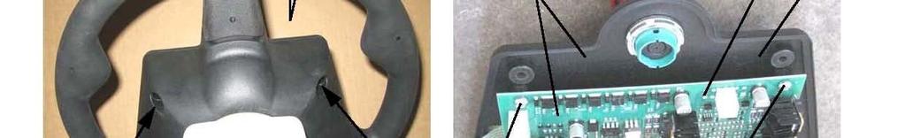
72 10.3 STEERING WHEEL DISASSEMBLY/ASSEMBLY Removal 1. Remove the electronic functions (see the procedure in the specific paragraph), but without separating the function board (1, Figure 10-3) from the support with the keyboard. 2. Operating on the steering wheel, disconnect the electrical cables (3) from the electrical connector (4) of the emergency stop switch. 3. Unscrew the central nut (5) of the steering wheel (6). 4. Using a workshop extractor, pull off the steering wheel (6) from the conical engagement with a key, exerting force on the point (7) opposite the points (8). To prevent damage to the steering wheel, apply force distribution shims to the areas (8). 5. Retrieve the conical engagement key. Assembly 6. Assemble, by reversing the sequence of operations performed for disassembly.
73 10.4 STEERING COLUMN DISASSEMBLY/ASSEMBLY Removal 1. Remove the steering wheel (See the procedure in the specific paragraph). 2. Unscrew the screws (1, Figure 10-4) and gently lift the steering column (2). 3. Disconnect the electrical connector (3) of the ignition key, and then remove The steering column (2). Assembly 4. Assemble, by reversing the sequence of operations performed for disassembly.


74 10.5 DISASSEMBLY/ASSEMBLY OF THE CLEAN WATER SIGHT GAUGE REMOVAL 1. Empty the detergent solution tank (or washing water) (See the procedure in the User and Maintenance Manual). 2. Make sure that the machine cannot move independently, and then turn the ignition key to " 0" and take it out. WARNING Wear gloves and protective clothing suitable for the task. 3. Operating carefully, using a sharp knife, remove the dipstick (1, Figure 10-5) to be replaced. ASSEMBLY 4. Operating on the tank of the machine, clean the adhesive residue from the dipstick housing; if necessary degrease the bonding area by means of a solvent. Clean and degrease the gluing perimeter of the new dipstick to be fitted. 5. Apply a uniform bead of "Gelson MS-Flex 445 Auto glass Repair Technicians MS-polymer based sealant" adhesive, or equivalent, without interruption, to the entire gluing perimeter of the new dipstick to be mounted. 6. Place the dipstick in the tank housing (1) and make the adhesive stick by pressing gently. 7. Apply the adhesive tapes positioning the dipstick on the tank. 8. Let the adhesive dry for 18 hours with the machine off.
 (See the procedure in the User and Maintenance Manual). 2.")

 drain hose (2) from the tank coupling. 5. Remove the hose (2) from the machine. Assembly 6.")
75 10.6 DISASSEMBLY/ASSEMBLY OF DRAIN HOSE FOR THE CLEAN WATER TANK Removal 1. Empty the detergent solution tank (or washing water) (See the procedure in the User and Maintenance Manual). 2. If available, place the machine on a lifting platform; otherwise, place the machine on a level floor. Make sure that the machine cannot move independently. 3. Turn the ignitioniti key to the "0" and take it out. 4. Operating on the right side of the machine, loosen the strap (1, Figure 10-6) and then disconnect the detergent solution (or washing water) drain hose (2) from the tank coupling. 5. Remove the hose (2) from the machine. Assembly 6. Assemble, by reversing the sequence of operations performed for disassembly.
. 2.")


76 10.7 DISASSEMBLY/ASSEMBLY RECOVERY WATER DRAIN HOSE Removal 1. Empty the recovery water tank (see the procedure in the User and Maintenance Manual). 2. If available, place the machine on a lifting platform, and raise it up; otherwise, place the machine on a level floor. Make sure that the machine cannot move independently. d 3. Turn the ignition key to the "0" and take it out. 4. Operating on the left side of the machine, loosen the strap well (1, Figure 10-7) and then disconnect the recovery water drain hose (2) from the tank coupling. If necessary, to facilitate the removal of the hose from the tank, open the battery drum (3) (See the procedure in the User and Maintenance Manual). 5 R th h (2) f th hi 5. Remove the hose (2) from the machine. Assemble 6. Assemble, by reversing the sequence of operations performed for disassembly.
77 11. ELECTRICAL SYSTEM The significant maintenance/replacement procedures relating to the Electrical system are described in this chapter. Troubleshooting and arrangement of the components of the electrical system is also described; the Wiring Diagram has also been inserted BATTERY CHARGING See procedure in the User and Maintenance Manual 11.2 BATTERY DISASSEMBLY/ASSEMBLY Removal 1. Remove the battery holder drum and disconnect the battery connector (1, Figure 11-1) (See the procedure in the User and Maintenance Manual). 2. Disengage the blade guards of the poles (2) of the batteries. 3. Disconnect the terminals from the poles (2) of the batteries and move the electrical cables (3). 4. Carefully remove the batteries (4). 5. Assemble, by reversing the sequence of operations performed for disassembly, with the following instruction: the batteries need to be reconnected according to the diagram (5). if you install another type of battery other than the batteries removed, the machine must be adjusted for the type of batteries installed, operating according to the following procedure:
78 11.2 Battery Wiring Adjusting the machine for the type of batteries installed Caution! In the context of the procedure described on the next page, concerning the "adjustment of the machine for the type of batteries installed", make sure you do not vary any other setting of the machine. The machine settings are set by the manufacturer to optimize the functional characteristics of the machine itself, and are then saved before selling the machine. Changing the machine settings (except those covered by this manual) by anyone not authorized to do so, may be lead to the revocation of the warrant of the machine and any other service contracts by the manufacturer.
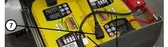
79 11.3 Battery Charger settings NOTE: Perform each operation within 10 seconds of the previous operation otherwise the board will be reset and you will have to resume operations from the start. 1. Turn the machine on. 2. During the start-up simultaneously press and hold down the (-) button of the water dosage and the (+) button of the detergent dosage - the display shows "USER CHECK - PASSWORD:0 3. Press the button (+) of the detergent dosage until you reach the number Press (Turbo) button. 5. Press the button (+) of the water dosage until the display shows "SET TARGET: FUNCTION BOARD" 6. Press the button (TURBO) to confirm - the display will show the type of battery the machine is set for. PB24", corresponding to WET lead acid batteries GeE24", corresponding to GEL batteries "Optima, corresponding to Optima AGM batteries AGM, corresponding to AGM batteries 7. Press water (+) button to select a different battery type. See above. 8. Wait for the machine to reset. 9. Turn the machine off and on again. 10.The new setting will take affect.
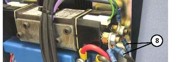
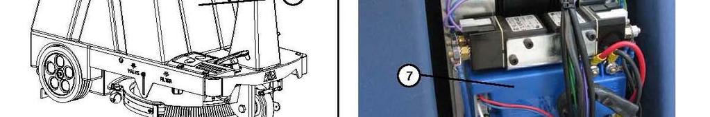
80 11.4 CHECKING/REPLACING FUSES 1. Make sure that the machine cannot move independently. 2. Turn the ignition key to the "0" and take it out. 3. Remove the battery holder drum and disconnect the battery connector (6, Figure 3-4) (See the procedure in the User and Maintenance Manual). 4. Open the cover (1, Figure 11-2) and remove the panel (2) by lifting it up. Lower the cover back down (1). Checking / replacing fuses: 10 A fuse, for protecting auxiliary services (3, Figure 11-2) 80 A fuse, drive protection board (4, Figure 11-2) 30 A fuse, for vacuum motor protection (5, Figure 11-2) 40 A fuse, for brush motor protection (6, Figure 11-2) 5. Reinstall the panel (2). 6. Connect the battery connector and close the battery holder drum.
81 11.4 Fuses
 (For the procedure,")
 and remove the panel (2) by lifting it up. Lower the cover back down (1).")
 from the drive electronic board (4). 5.")
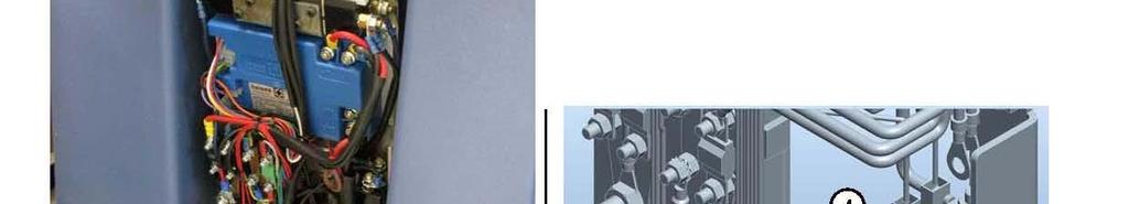
82 11.5 DISASSEMBLY/ASSEMBLY DRIVE ELECTRONIC BOARD Remove 1. Remove the battery holder drum and disconnect the battery connector (6, Figure 3-4) (For the procedure, see the User and Maintenance Manual). 2. Open the cover (1, Figure 11-3) and remove the panel (2) by lifting it up. Lower the cover back down (1). 3. Disconnect the electrical connections (5) from the drive electronic board (4). board (4). 4. Disconnect the electrical connections (5) from the drive electronic board (4). 5. Unscrew the screws (6) and remove the electronic drive board (4). Assembly 6. Assemble, by reversing the sequence of operations performed for disassembly.
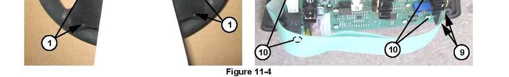
83 11.6 DISASSEMBLY/ASSEMBLY FUNCTIONS ELECTRONIC BOARD Removal 1. If available, place the machine on a lifting platform, otherwise, place the machine on a level floor. Make sure that the machine cannot move independently. 2. Turn the ignition key to the "0" and take it out. 3. Remove the battery holder drum and disconnect the battery connector (6, Figure 3-4) (For the procedure, see the User and Maintenance Manual). 4. Operating under the steering wheel, unscrew the screws (1, Figure 11-4) 5. Carefully lift the keyboard assembly with an electronic board functions (2). 6. Disconnect the electrical connections (5) from the functions electronic board (4). 7. Turn the lever (5) and disconnect the electrical connector (6) from the emergency stop switch (7). 8. Retrieve the keyboard assembly with functions electronic board (2). 9. On a workbench, disconnect the electrical connectors (9) for the keyboard wiring from the functions electronic board (8) of the keyboard. 10. Unscrew the 10 screws 11. Separate functions electronic board (8) from the support with keyboard (13). Assembly Assemble, by reversing the sequence of operations performed for disassembly, with the following instruction. ti Before positioning the keyboard assembly in the housing with functions electronic board (12), check that the perimeter seal (11) is efficiently and correctly positioned in the housing.

84


. Assembly 3.")
85 11.7 KEY SWITCH INSTALLATION Removal 1. Remove the steering column (See the procedure in the specific paragraph). 2. Operating from inside the steering column (1, Figure 11-5), loosen the lock nut (2) and remove the ignition key (3). Assembly 3. Assemble, by reversing the sequence of operations performed for disassembly
 2. Broken batteries (check flat battery voltage) 3.")
86 11.8 TROUBLE SHOOTING See the other chapters, as already indicated for other systems that use the electrical system. Also other possible causes of failure can be: 1. Flat batteries or their connections not efficient (charge battery or clean the connections) 2. Broken batteries (check flat battery voltage) 3. Battery Charger failure (replace it) (only for the version with the charger in the machine) 4. Interrupted fuses (replace them) 5. Electrical wiring cut or crushed in short circuit (repair it) 11.9 ALARM CODES Any active alarms on the machine are displayed using the display (3, Figure 3-1)ofthe control panel. Alarms can relate to the functions board (CFI0000, identified as "Control Alarm#") or drive board (7CH4Q90A, identified as "Drive Alarm#"). The following are two examples of alarms by board type and the summary tables of alarms with instructions/solutions.
Tornado Operations & Maintenance Manual
 TORNADO INDUSTRIES 7401 W. LAWRENCE AVENUE CHICAGO, IL 60706 (708) 867-5100 FAX (708) 867-6968 www.tornadovac.com Tornado Operations & Maintenance Manual MODEL NO. 99690 BD 22/14, 99720 BD 26/14 L9722
ScrubMaster 30R OPERATING & MAINTENANCE
 ScrubMaster 30R INTRODUCTION OPERATING & MAINTENANCE INSTRUCTIONS READ THIS BOOK This operator s book has important information for the use and safe operation of this machine. Read this book carefully
ScrubMaster 26C OPERATING & MAINTENANCE
 ScrubMaster 26C INTRODUCTION OPERATING & MAINTENANCE INSTRUCTIONS READ THIS BOOK This operator s book has important information for the use and safe operation of this machine. Read this book carefully
Tornado Operations & Maintenance Manual
 Tornado Industries, LLC 333 Charles Court West Chicago, IL 60185 www.tornadovac.com Tornado Operations & Maintenance Manual MODEL NO. 99414 Form No. L9740AB Tornado Industries, LLC. All rights reserved
Tornado Operations & Maintenance Manual
 TORNADO INDUSTRIES 7401 W. LAWRENCE AVENUE CHICAGO, IL 60706 (708) 867-5100 FAX (708) 867-6968 www.tornadovac.com Tornado Operations & Maintenance Manual MODEL NO. 99760 BD26/30 & 99780 BD33/30 L9718AB
To Order Parts Call
 5 SUMMARY ON CONSIGNMENT OF THE MACHINE...6 INTRODUCTORY COMMENT...6 TECHNICAL DATA...6 SYMBOLOGY USED ON THE MACHINE...7 SYMBOLOGY USED IN THE MANUAL...9 MACHINE PREPARATION...30. HANDLING OF THE PACKED
SYMBOLOGY USED ON THE MACHINE
 SUMMARY ON CONSIGNMENT OF THE MACHINE...34 INTRODUCTORY COMMENT...34 TECHNICAL DATA...34 SYMBOLOGY USED ON THE MACHINE...35 MACHINE PREPARATION...38 1. HANDLING OF THE PACKED MACHINE...38 2. HOW TO UNPACK
Scrubbing machine. Use and Maintenance manual
 Scrubbing machine Use and Maintenance manual ORIGINAL INSTRUCTIONS DOC. 10074280 - Ver. AA - 10-2017 The descriptions contained in this document are not binding. The company therefore reserves the right
coral 65 coral 65 II coral 85
 coral 65 coral 65 II coral 85 01 2016 Use and maintenance Attention! Please read the instructions before use. TECHNICAL DESCRIPTION U/M coral 65 coral 65 II coral 85 Cleaning width Squeegee width Working
Parts and Service Manual
 Section II Parts and Service Manual (70241A) CLARKE TECHNOLOGY Operator's Manual - MINI MAX Page -29- Frame and Front Cover Assembly Drawing 2/01 Page -30- CLARKE TECHNOLOGY Operator's Manual -MINI MAX
Operating Instructions
 Operating Instructions BA-003 Read and understand this manual before use. Keep this manual for future reference. CONFORMS TO UL STD.No.1017 Certified to CSA STD C22.2 No.243-10 For questions or concerns
MERCURY HD-22 AUTOSCRUBBER Safe Operations
 Safe Operations PROPER OPERATING PROCEDURES By following proper operating procedures, the Mercury DS- 26 Autoscubber can provide you with productive, easy to operate, safe and clean floors. This machine
jade 50 jade 55 jade 66
 jade 50 jade 55 jade 66 01 2015 Use and maintenance Attention! Please read the instructions before use. COD. 65302007 TECHNICAL DESCRIPTION U/M jade 50 jade 55 jade 66 Cleaning width Squeegee width Working
SCRUBBER. Operating Instructions (ENG) MODELS: SG28 SG32 SG36 ENDING WITH SN: IPX4. Read these instructions before using the machine
 MODELS: SG28 SG32 SG36 ENDING WITH SN: IPX4. Read these instructions before using the machine") SCRUBBER Operating Instructions (ENG) MODELS: SG28 SG32 SG36 ENDING WITH SN: 1000136404 IPX4 Read these instructions before using the machine AV 98950 12/11/04 MACHINE DATA LOG/OVERVIEW MODEL DATE OF PURCHASE
SCRUBBER Operating Instructions (ENG) MODELS: SG28 SG32 SG36 ENDING WITH SN: 1000136404 IPX4 Read these instructions before using the machine AV 98950 12/11/04 MACHINE DATA LOG/OVERVIEW MODEL DATE OF PURCHASE
OWNERS MANUAL ST50BT
 OWNERS MANUAL ST50BT NaceCare Solutions 1205 Britannia Road East, Mississauga, ON L4W 1C7 Phone: 1-800-387-3210 Fax: 1-800-709-2896 SUMMARY SUMMARY...2 ON CONSIGNMENT OF MACHINE...3 INTRODUCTION...3 MACHINE
Operator s Manual. 6 Gallon Model No. VQ607SFD FOR YOUR SAFETY. Read and understand this manual before use Keep this manual for future reference
 Wet/Dry Vacuums Operator s Manual 6 Gallon Model No. VQ607SFD FOR YOUR SAFETY Read and understand this manual before use Keep this manual for future reference www.vacmaster.com Cleva North America 44 Parkway
WET/DRY VACUUM. QUEST for Continuous Improvement Windsor s Quality Management System is Certified ISO MODEL: T1. Operating Instructions (ENG)
") WET/DRY VACUUM Operating Instructions (ENG) MODEL: T1 y QUEST for Continuous Improvement Windsor s Quality Management System is Certified ISO 9001. Read these instructions before operating the machine.
WET/DRY VACUUM Operating Instructions (ENG) MODEL: T1 y QUEST for Continuous Improvement Windsor s Quality Management System is Certified ISO 9001. Read these instructions before operating the machine.
DRS21BT STEALTH. 21 MicroRider Automatic Scrubber. Operator Manual E E E
 E29961-00 E29962-00 E29963-00 STEALTH DRS21BT 21 MicroRider Automatic Scrubber Operator Manual 1001 Brown Avenue Toledo, Ohio 43607-0127 Customer Service: 888-GO-BETCO Fax: 800-445-5056 Technical Service:
Fig. 2. Fig. 1. Fig. 3. Fig. 4. Fig. 5. Fig. 7 Fig. 6. Fig. 9. Fig. 8. Fig. 10 MAX H2O
 R 1 2 23 3 5 6 7 10 9 8 4 13 19 23 18 12 17 21 16 11 22 14 15 20 Fig. 1 Fig. 2 2 1 Fig. 3 Fig. 4 MAX H2O 1 Fig. 5 2 Fig. 7 Fig. 6 Fig. 9 Fig. 8 Fig. 10 E N G L I S H KEY 1) Carrying handle 2) Mains ON/OFF
CAUTION: Read the Operator's Manual before using the appliance.
 Division of Operator's Manual READ THIS BOOK CAUTION: Read the Operator's Manual before using the appliance. This book has important information for the use and safe operation of this machine. Failure
User Manual. Floor Scrubber Disc Brush Drive
 User Manual Floor Scrubber Disc Brush Drive This manual is furnished with each new Floor Scrubber. This provides the necessary operating and preventive maintenance instructions. Operators must read and
14 Upright Vacuum with HEPA Filter & Dual Power
 E29990-00 14 Upright Vacuum with HEPA Filter & Dual Power Operator and Parts Manual 1001 Brown Avenue Toledo, Ohio 43607-0127 Customer Service: 888-GO-BETCO Fax: 800-445-5056 Technical Service: 877-856-5954
Model: C C Ambassador 20. Automatic Carpet Scrubber OPERATION SERVICE PARTS CARE
 Ambassador 20 Automatic Carpet Scrubber Model: C8420-115 C8420-240 OPERATION SERVICE PARTS CARE This manual is furnished with each new Minuteman Ambassador 20. This provides the necessary operating and
APW PSI PRESSURE WASHER
 APW5001 1300 PSI PRESSURE WASHER 1300 PSI PRESSURE WASHER Please carefully read this manual which has been specifically designed to provide all the necessary information for the correct use of the machine,
ruby 45t ruby 50t ruby 50bh ruby 55t
 ruby 45t ruby 50t ruby 50bh ruby 55t 01 2015 Use and maintenance Attention! Please read the instructions before use. COD. 65301008 TECHNICAL DESCRIPTION U/M ruby 45t ruby 50t ruby 50bh ruby 55t Cleaning
opal 66 opal 80 COD Use and maintenance Attention! Please read the instructions before use.
 opal 66 opal 80 09 2014 Use and maintenance Attention! Please read the instructions before use. COD. 65314001 TECHNICAL DESCRIPTION U/M opal 66 opal 80 Cleaning width Squeegee width Working capacity, up
Operator s Manual. Wet/Dry Vacuum with Detachable Blower 12 Gallon Model No. VBV1210 FOR YOUR SAFETY
 Wet/Dry Vacuums Operator s Manual Wet/Dry Vacuum with Detachable Blower 12 Gallon Model No. VBV1210 FOR YOUR SAFETY Read and understand this manual before use Keep this manual for future reference www.vacmaster.com
User Manual. Floor Scrubber Traction Drive
 User Manual Floor Scrubber Traction Drive This manual is furnished with each new Floor Scrubber. This provides the necessary operating and preventive maintenance instructions. Operators must read and understand
Electronic Service Manuals
 Electronic Service Manuals This electronic document is provided as a service to our customers. We do not create the contents of the information contained in this document. Should you have detailed questions
Canister Vacuums S6EVO. Operations and Parts Manual. Models: S6EVO
 Canister Vacuums S6EVO Operations and Parts Manual Models: S6EVO 2 IMPORTANT SAFETY INSTRUCTIONS When using an electrical appliance, basic precaution must always be followed, including the following: READ
Sanitaire. Owner s Guide. 10 GALLON Box Extractor SC6088 Series IMPORTANT
 Sanitaire 10 GALLON Box Extractor SC6088 Series Part No. SC6088 Rev 2 (3/14) Owner s Guide IMPORTANT Do not return this product to the store. Call 1-800-800-8975* Monday - Friday 8:00 AM to 7:30 PM and
T1 SCRUBBER DRYER OPERATOR MANUAL
 T1 SCRUBBER DRYER OPERATOR MANUAL Clemas & Co. Unit 5 Ashchurch Business Centre, Alexandra Way, Tewkesbury, Gloucestershire, GL20 8NB. Tel: 01684 850777 Fax: 01684 850707 Email: info@clemas.co.uk Web:
INSTRUCTION MANUAL 4HP WET / DRY VACUUM VC V 60 Hz 7A. Gal
 INSTRUCTION MANUAL WET / DRY VACUUM VC25180 Note : Read and understand this manual before use. Keep this manual for future reference. 4HP 8 Gal 120 V 60 Hz 7A C US TABLE OF CONTENTS SECTION Warranty...
Scrubber User Manual
 Scrubber User Manual AS430C VIPER NORTH AMERICA [866] 418-4737 [866] 41-VIPER VF90031-US Rev.01 TABLE OF CONTENTS USER MANUAL INTRODUCTION... 2 CONTENTS............................. 2 PURPOSE.............................
Service Manual for X9.5 and Older Models
 Service Manual for X9.5 and Older Models I. Common Issues... 2 A. Direct Air Motor... 2 A.1. Direct Air Motor will not run.... 2 A.2. Direct Air Motor is making a squealing sound.... 2 B. Full Bag Indicator
iscrub IPX4 Operating instructions (ENG) MODELS: CSX CSX24X CSXE CS26SP CS26SPX
 MODELS: CSX CSX24X CSXE CS26SP CS26SPX") iscrub Operating instructions (ENG) MODELS: CSX24 10061090 CSX24X 10061100 CSXE24 10061120 CS26SP 10061160 CS26SPX 10061170 Read these instructions before using the machine. 86317500-AT 08/2012 IPX4 Machine
iscrub Operating instructions (ENG) MODELS: CSX24 10061090 CSX24X 10061100 CSXE24 10061120 CS26SP 10061160 CS26SPX 10061170 Read these instructions before using the machine. 86317500-AT 08/2012 IPX4 Machine
OPERATOR S MANUAL FOR YOUR SAFETY. 4 Gallon / Liter Part No. PB408SV
 120 VOLT WET / DRY VAC 4 Gallon / 15.14 Liter Part No. PB408SV FOR YOUR SAFETY Read and understand this manual before use. Keep this manual for future reference. OPERATOR S MANUAL TABLE OF CONTENTS SECTION
Operator s Manual. 2.5 Gallon Model No. VOM205P FOR YOUR SAFETY. Read and understand this manual before use. Keep this manual for future reference.
 Wet/Dry Vacuums Operator s Manual 2.5 Gallon Model No. VOM205P FOR YOUR SAFETY Read and understand this manual before use. Keep this manual for future reference. www.vacmaster.com Cleva North America 44
INNOVA B 70 S
 USE AND MAINTENANCE MANUAL INNOVA 2011 60-65-75-85 B 70 S ED. 06-2012 EN ORIGINAL INSTRUCTIONS Doc. 10029401 Ver. AB The descriptions contained in this document are not binding. The company therefore reserves
IMAGE V. Parts and Service Manual
 IMAGE 0V Section II Parts and Service Manual (88B) CLARKE TECHNOLOGY Image Operator's Manual Page AUTHORIZED PERSONNEL MAINTENANCE To Access Pump Motor. Remove brush housing from machine. See "Brush Motor
Scrubbing machine. Use and Maintenance manual
 Scrubbing machine Use and Maintenance manual Original istruction - DOC. 0075453 Ver. AA - 0-07 The descriptions contained in this document are not binding. The company therefore reserves the right to
Operator s Manual. Floor Vac Model No. VF408 FOR YOUR SAFETY. Read and understand this manual before use Keep this manual for future reference
 Wet/Dry Vacuums Operator s Manual Floor Vac Model No. VF408 FOR YOUR SAFETY Read and understand this manual before use Keep this manual for future reference www.vacmaster.com Cleva North America 44 Parkway
Operations and Parts Manual
 Canister Vacuums Hospital Vac Operations and Parts Manual Models: S9HOSPITAL 2 IMPORTANT SAFETY INSTRUCTIONS When using an electrical appliance, basic precaution must always be followed, including the
WET/DRY VACUUMS POLYETHYLENE, POLYPROPYLENE & STEEL
 WET/DRY VACUUMS POLYETHYLENE, POLYPROPYLENE & STEEL MODELS: 315P 415P 429P 415S 415ST 415PLT 429ST OPERATIONS AND PARTS MANUAL IMPORTANT READ THIS MANUAL PRIOR TO USE. TABLE OF CONTENTS Page No. Important
Tornado Operations & Maintenance Manual
 TORNADO INDUSTRIES, LLC 7401 W. Lawrence Avenue Chicago, IL 60706 Ph (708) 867-5100 Fax (708) 867-6968 www.tornadovac.com Tornado Operations & Maintenance Manual MODEL NO. 99410 BR 13/1MW L9735Rev_C Tornado
SSS Jaguar 26R Ride-on Automatic Scrubber
 SSS Jaguar 26R Ride-on Automatic Scrubber Instruction for Use - Original Instructions Model: 86015-26 Disc - EcoBoss - Charger English 04-2015(1) FORM NO. 9100001306 INSTRUCTIONS FOR USE ENGLISH TABLE
PRESSURE WASHER MODEL NO: JETSTAR 1750 OPERATION & MAINTENANCE INSTRUCTIONS. WARNING Read the instructions before using the machine PART NO:
 WARNING Read the instructions before using the machine PRESSURE WASHER MODEL NO: JETSTAR 1750 PART NO: 7333230 OPERATION & MAINTENANCE INSTRUCTIONS LS0711 INTRODUCTION Thank you for purchasing this CLARKE
AS20B CREWMAN. 20 Automatic Scrubber with Brush Assist. Operator Manual E E E
 E83025-00 E29936-00 E29937-00 CREWMAN AS20B 20 Automatic Scrubber with Brush Assist Operator Manual 400 Van Camp Road Bowling Green, Ohio 43402 Customer Service: 888-GO-BETCO Fax: 800-445-5056 Technical
Wet/Dry Vacuum Kit
 Wet/Dry Vacuum Kit 54-0011-6 Owner ' s Manual Toll-Free Helpline: 1-866-JOBMATE (562-6283) Version 3.3 Table of Contents SECTION Page Specifications...2 Safety Warnings... 3 Location of Parts..... 5 General
WET & DRY VACUUM CLEANER
 VMVK1520SIWC / 1500W / 20L WET & DRY VACUUM CLEANER VMVK1520SIWC table OF CONTENTS SECTION page Warranty 3 Safety Instructions and Warnings 3 Specifications 4 Unpacking and Checking Carton Contents 4 General
User Manual GV25 GV35 GV702. Company information: Original instructions GV12066 (1)
") User Manual Original instructions GV25 GV35 GV702 Company information: www.vipercleaning.eu info-eu@vipercleaning.com GV12066 (1) 2012-04-10 USER MANUAL ENGLISH TABLE OF CONTENTS Introduction... 4 Manual
User Manual Original instructions GV25 GV35 GV702 Company information: www.vipercleaning.eu info-eu@vipercleaning.com GV12066 (1) 2012-04-10 USER MANUAL ENGLISH TABLE OF CONTENTS Introduction... 4 Manual
SCV 28/32 RIDER SCRUBBER OPERATION SERVICE PARTS CARE
 SCV 28/32 RIDER SCRUBBER OPERATION SERVICE PARTS CARE This manual is furnished with each new MINUTEMAN SCV TM 28/32. This provides the necessary operating and preventive maintenance instructions. Operators
GALAXY FLOOR MACHINE
 OPERATION MANUAL GALAXY FLOOR MACHINE IMPORTANT SAFETY INSTRUCTIONS WARNING: Failure to observe these instructions can cause personal injury to machine operator or bystanders. WARNING: Shock or electrocution
NSS STANDARD-SPEED FLOOR MACHINES
 OPERATION MANUAL NSS STANDARD-SPEED FLOOR MACHINES IMPORTANT SAFETY INSTRUCTIONS Read all instructions before using or servicing machine. WARNING: Fire or explosion hazard. NEVER use with flammable or
ZD-985 Desoldering Station
 ZD-985 Desoldering Station 2 Contents Contents... 3 Unpacking and Setting Up Your ZD-985 Desoldering Station... 4 Setting Up the Unit... 5 Auto Tip Saver Function... 8 Tips and Techniques... 8 Alloy Melt
BIOCIDE ANTIMICROBIAL DRY VACUUM
 BIOCIDE ANTIMICROBIAL DRY VACUUM Model: ATIBCV IMPORTANT SAFETY INSTRUCTIONS When using an electrical appliance, basic precaution must always be followed, including the following: READ ALL INSTRUCTIONS
OWNERS MANUAL ST900 SERIES
 OWNERS MANUAL ST900 SERIES 1205 Britannia Road East, Mississauga, ON L4W 1C7 Phone: 1-800-387-3210 Fax: 1-800-709-2896 ON CONSIGNMENT OF THE MACHINE When the machine is consigned to the customer, an immediate
Installation Instructions Part No , Part No Part No
 Torsion-Flex Motor mount for PSC motors and Rigid-Mount for ECM motors Replacement Kit Cancels: New Installation Instructions Part No. 327752-401, Part No. 327753-401 Part No. 327754-401 IIK-310A-45-11
Specifications. Vacuum motor power consumption(w/hp) 1200 / 1.6. Exhaust water pump power consumption(w/hp 800 / 1.1
 1200 / 1.6. Exhaust water pump power consumption(w/hp 800 / 1.1") Specifications Rated voltage (V) AC 110-120V or 220-240V / 50-60Hz Vacuum motor power consumption(w/hp) 1200 / 1.6 Exhaust water pump power consumption(w/hp 800 / 1.1 Exhaust water pump flow (GPH/LPH)
Specifications Rated voltage (V) AC 110-120V or 220-240V / 50-60Hz Vacuum motor power consumption(w/hp) 1200 / 1.6 Exhaust water pump power consumption(w/hp 800 / 1.1 Exhaust water pump flow (GPH/LPH)
Mopit 4 Operator s / Service Manual
 Mopit 4 Operator s / Service Manual FOR PARTS AND SERVICE 1-800-290-2833 To view Mopit 4 instructional videos scan this qr code with your smart phone. You can also find Mopit 4 instructional videos on
SSS Intrepid 16 FMS. Manual
 SSS Intrepid 16 FMS Manual The contents of this manual are based on the latest product information available at the time of publication. Triple S reserves the right to make changes or improvements to its
MC MC MC MC MC833130
 Pic-A-Vac Model: MC832085 MC833085 MC832105 MC833105 MC832130 MC833130 OPERATION SERVICE PARTS CARE Revised 8/01 FOR COMMERCIAL USE ONLY IMPORTANT SAFETY INSTRUCTIONS When using an electrical appliance,
5700XPS. *mm402* Operator Manual. MM402 Rev.15
 5700XPS Operator Manual MM402 Rev.15 *mm402* This manual is furnished with each new TENNANT Model 5700XPS. It provides necessary operating and preventive maintenance instructions. Read this manual completely
FLAME115 INFRARED HEATER SERVICE MANUAL INDEX FIRE 115 WARNING
 FLAME115 INFRARED HEATER SERVICE MANUAL INDEX 1. CONTROLS AND COMPONENTS 2. FLAME CONTROL CYCLES 3. MAINTENANCE SCHEDULE 4. TROUBLESHOOTING GUIDE 5. REPAIR PROCEDURES 1. FAN MOTOR ASSEMBLY 2. FUEL FILTER
Safety. Rinse Kit for Multi-Pro 1200 and 1250 Turf Sprayers Model No Safety and Instructional Decals. Installation Instructions
 Rinse Kit for Multi-Pro 1200 and 1250 Turf Sprayers Model No. 106-4842 Form No. 3353-529 Rev B Installation Instructions Note: Determine the left and right sides of the machine from the normal operating
User s Guide REO-MECH. Industrial Rebar Benders & Cutters
 User s Guide REO-MECH Industrial Rebar Benders & Cutters WARNING: PLEASE READ THIS MANUAL CAREFULLY BEFORE USING THIS MACHINE Machine is not rated and should not be used for commercial rebar production
TROUBLESHOOTING VANGUARD
 TROUBLESHOOTING VANGUARD IMPORTANT: Only a qualified Service Person should service internal components or electrical wiring. WARNING: Disconnect electrical power to the Unit to prevent personal injury
User Manual. Phoenix 20 Floor Scrubber Disc Brush Drive
 User Manual Phoenix 20 Floor Scrubber Disc Brush Drive This manual is furnished with each new PowerBoss Phoenix 20. This provides the necessary operating and preventive maintenance instructions. Operators
OWNER S MANUAL. IMPORTANT: READ OWNER S MANUAL CAREFULLY Please fill out and return your warranty card MODEL &
 OWNER S MANUAL IMPORTANT: READ OWNER S MANUAL CAREFULLY Please fill out and return your warranty card MODEL 261123 & 261124 032911 TABLE OF CONTENTS CONGRATULATIONS on your purchase of a Global product.
OPERATOR'S MANUAL. IMPORTANT: READ OPERATOR'S MANUAL CAREFULLY Please fill out & return your warranty card! DP80405
 CARBON SPOT 30 EXTRACTOR OPERATOR'S MANUAL IMPORTANT: READ OPERATOR'S MANUAL CAREFULLY Please fill out & return your warranty card! DP80405 Diamond Products www.diamondproductsus.com Printed in the U.S.A.
I N ST R UC T I ON. MODEL HAB500 AroMatic TM BREAD SLICERS MODEL FORM (4-99) AROMATIC BREAD SLICER 701 S. RIDGE AVENUE TROY, OHIO
 AROMATIC BREAD SLICER 701 S. RIDGE AVENUE TROY, OHIO") I N ST R UC AROMATIC BREAD SLICER T I ON S MODEL HAB500 AroMatic TM BREAD SLICERS MODEL HAB500 ML-104845 701 S. RIDGE AVENUE TROY, OHIO 45374-0001 FORM 34198 (4-99) TABLE OF CONTENTS GENERAL..........................................................
I N ST R UC AROMATIC BREAD SLICER T I ON S MODEL HAB500 AroMatic TM BREAD SLICERS MODEL HAB500 ML-104845 701 S. RIDGE AVENUE TROY, OHIO 45374-0001 FORM 34198 (4-99) TABLE OF CONTENTS GENERAL..........................................................
MANUAL USE AND MAINTENANCE FLEXY 75B-85B ED Doc Ver. AB
 MANUAL USE AND MAINTENANCE FLEXY 75B-85B ED. 03-2009 EN Doc. 10015846 Ver. AB The contained descriptions in the present publication are not binding. The company therefore reserves itself the right to bring
User Manual FANG 18 C. Company information: Original instructions 80188EU (1)
") User Manual Original instructions FANG 18 C Company information: www.vipercleaning.eu info-eu@vipercleaning.com 80188EU (1) 2012-04-10 USER MANUAL ENGLISH TABLE OF CONTENTS Introduction... 4 Manual purpose
User Manual Original instructions FANG 18 C Company information: www.vipercleaning.eu info-eu@vipercleaning.com 80188EU (1) 2012-04-10 USER MANUAL ENGLISH TABLE OF CONTENTS Introduction... 4 Manual purpose
User Manual. E17/E20 Electric Walk-Behind Scrubber Disc Brush Drive
 User Manual E17/E20 Electric Walk-Behind Scrubber Disc Brush Drive This manual is furnished with each new MINUTEMAN E17/E20. This provides the necessary operating and preventive maintenance instructions.
π H-2268 SANITAIRE UPRIGHT VACUUM SAFETY uline.com
 π H-2268 SANITAIRE UPRIGHT VACUUM 1-800-295-5510 uline.com SAFETY PAGE 1 OF 7 NOTE: When using an electrical appliance, basic precautions should always be followed, including the following: READ ALL INSTRUCTIONS
XPS-ProDry User s Guide Dryer Base
 XPS-ProDry User s Guide XPS-ProDry User s Guide Dryer Base For Use with Inkjet Imaging Systems Manual Part#: M-3120 Revision: August 2005 XPS-ProDry User s Guide Written by Frank Mauri & John Brand Published
Nilfisk Inc Winnetka Avenue North Minneapolis, MN REV.03( ) VF80189
 VF80189") Nilfisk Inc. 9435 Winnetka Avenue North Minneapolis, MN 55445 www.usviper.com REV.03(05-) VF8089 SAFETY PRECAUTIONS This machine is intended for commercial use. It is constructed for use in an indoor
Nilfisk Inc. 9435 Winnetka Avenue North Minneapolis, MN 55445 www.usviper.com REV.03(05-) VF8089 SAFETY PRECAUTIONS This machine is intended for commercial use. It is constructed for use in an indoor
User Manual. E20 Walk-Behind Scrubber Traction Drive Cylindrical Deck
 User Manual E20 Walk-Behind Scrubber Traction Drive Cylindrical Deck This manual is furnished with each new MINUTEMAN E20. This provides the necessary operating and preventive maintenance instructions.
INSTRUCTIONS FOR USE PORTABLE VACUUM SYSTEM LEI Part # s / , , , IMPORTANT INFORMATION
 INSTRUCTIONS FOR USE PORTABLE VACUUM SYSTEM LEI Part # s / 27-009, 27-010, 27-015, 27-020 IMPORTANT INFORMATION UNATHORIZED CHANGES OR ALTERATIONS TO ANY LINCOLN PORTABLE VACUUM SYSTEM WILL AUTOMATICALLY
Turbo Stick Vac. OWNER S MANUAL Model EP V., 60Hz., 7.5 Amps.
 OWNER S MANUAL Model EP600 120V., 60Hz., 7.5 Amps. Turbo Stick Vac For information or assistance: EURO-PRO Operating LLC 94 Main Mill Street, Door 16 Plattsburgh, NY 12901 Tel.: 1 866 98SHARK (74275) www.sharkvac.com
INSTRUCTION MANUAL MODEL: 690E
 1 INSTRUCTION MANUAL ALEKO Drywall Sander MODEL: 690E READ THROUGH CAREFULLY AND UNDERSTAND THESE INSTRUCTIONS BEFORE USE Visit our web site for more great products, parts and accessories: 2 3 4 5 6 Caution!
Pump Out Vacuums Polyethylene & Steel
 Pump Out Vacuums Polyethylene & Steel Operations and Parts Manual 110 volt receptacle on single motor only Models: 415P-AD 429P-AD 415DS IMPORTANT SAFETY INSTRUCTIONS When using an electrical appliance,
User Manual. Phoenix 20 Walk-Behind Scrubber Traction Drive Cylindrical Deck
 User Manual Phoenix 20 Walk-Behind Scrubber Traction Drive Cylindrical Deck This manual is furnished with each new Phoenix 20. This provides the necessary operating and preventive maintenance instructions.
PUREPOWER SERIES CENTRAL VACUUM POWER UNITS PP500, PP600 & PP650
 USER GUIDE PUREPOWER SERIES CENTRAL VACUUM POWER UNITS PP500, PP600 & PP650 AB0039 FOR RESIDENTIAL USE ONLY!! MODELS SFDB-DQ, SFDB-DR AND SFDB-DS 30042509E IMPORTANT SAFETY INSTRUCTIONS SAVE THESE INSTRUCTIONS
G-7s. Instruction Manual. G-Series Cooler COUNTERTOP COOLER. Part No.11IPA
 G-Series Cooler COUNTERTOP COOLER Part No.11IPA-061000 Instruction Manual FOR YOUR FUTURE REFERENCE This easy-to-use manual will guide you in getting the best use of your cooler. Remember to record the
Owner s Guide. Powerhead Canister Vacuum Cleaner
 Owner s Guide Powerhead Canister Vacuum Cleaner INDEX 1. Important Safety Instructions 2. Components & Accessories 3. Assembly 4. How to Operate a. On/Off Switch b. Check bag indicator c. Variable suction
FD 430 Envelope Sealer
 FD 430 Envelope Sealer 1/2018 OPERATOR, MAINTENANCE, & PARTS MANUAL REV. 1 2 CONTENTS 1 SAFETY INSTRUCTIONS... 5 1.1 Symbols and reference key... 5 1.2 Basic safety precautions... 6 1.3 Safety advice...
GULPER 16SV 16 GALLON WET/DRY VACUUM WITH FRONT MOUNT SQUEEGEE
 GULPER 16SV 16 GALLON WET/DRY VACUUM WITH FRONT MOUNT SQUEEGEE INTRODUCTION OPERATING & MAINTENANCE INSTRUCTIONS This operator s book has important information for the use and safe operation of this machine.
MODEL MC-UL592 MC-UL594 POWER SOURCE. 230V - 240V ~ 50 Hz MAX INPUT 1400 W 1500 W NOMINAL INPUT DIMENSIONS (W x L x H)
") Order Number: PMMA091040CE Vacuum Cleaner MC-UL592/MC-UL594 SPECIFICATION MODEL MC-UL592 MC-UL594 POWER SOURCE 230V - 240V ~ 50 Hz MAX INPUT 1400 W 1500 W NOMINAL INPUT DIMENSIONS (W x L x H) 1200-1300
Order Number: PMMA091040CE Vacuum Cleaner MC-UL592/MC-UL594 SPECIFICATION MODEL MC-UL592 MC-UL594 POWER SOURCE 230V - 240V ~ 50 Hz MAX INPUT 1400 W 1500 W NOMINAL INPUT DIMENSIONS (W x L x H) 1200-1300
π H-7147 SANITAIRE EON QUIET CLEAN VACUUM SAFETY uline.com
 π H-7147 SANITAIRE EON QUIET CLEAN VACUUM 1-800-295-5510 uline.com SAFETY PAGE 1 OF 9 NOTE: When using an electrical appliance, basic precautions should always be followed, including the following: READ
Cable Drum Machine. Operation Manual 40 SERIES. Cleans 2" to 4" lines up to 75' N O T F O R R O O T S
 Cable Drum Machine Operation Manual 40 SERIES Cleans 2" to 4" lines up to 75' Used For: Sinks, Showers & Floor Drains N O T F O R R O O T S WARNING - Read All Instructions, When Using Electric Tools, Basic
WARNING: OPERATOR MUST READ AND UNDERSTAND THIS MANUAL COMPLETELY BEFORE OPERATING THIS EQUIPMENT.
 OPERATOR S MANUAL & PARTS LIST Automatic Scrubber PAS14G WARNING: OPERATOR MUST READ AND UNDERSTAND THIS MANUAL COMPLETELY BEFORE OPERATING THIS EQUIPMENT. Tacony Corporation, All rights reserved Save
Vantage 17 Cable. Operator s Manual Manuel d utilisation Libro de Instrucciones
 Operator s Manual Manuel d utilisation Libro de Instrucciones READ THIS BOOK LEA ESTE MANUAL LISEZ CE MANUEL EN ES FR English (3-21) Español (23-41) Français (43-62) This book has important information
Service Manual Trash Compactor Models 15XESSEXF A November 2010 Broan-NuTone LLC 926 West State Street Hartford, WI
 Service Manual Trash Compactor Models 15XESSEXF 99044663A November 2010 Broan-NuTone LLC 926 West State Street Hartford, WI 53027 1-800-637-1453 2 Safe Servicing Practices Safe Servicing Practices To avoid
ORIGINAL INSTRUCTIONS
 WARNING: Read the instructions before using the machine. POWER WASHER MODEL NO: JETSTAR 1950 PART NO: 7336010 OPERATION & MAINTENANCE INSTRUCTIONS ORIGINAL INSTRUCTIONS LS0617 - ISS 3 INTRODUCTION Thank
D14 & D18 Upright Vacuum
 Operator's Manual D14 & D18 Upright Vacuum READ THIS BOOK This book has important information for the use and safe operation of this machine. Failure to read this book prior to operating or attempting
WET/DRY VACUUM Models PF51, PF53, PF55, PF57
 WET/DRY VACUUM Models PF51, PF53, PF55, PF57 OPERATING INSTRUCTIONS COMMERCIAL WET/DRY VACUUM Equipment must be operated, serviced and maintained in accordance with the manufacturer s instructions. Save
OPERATOR S MANUAL & PARTS LIST
 OPERATOR S MANUAL & PARTS LIST Crossover Automatic Scrubber Model PAS26R Tacony, Inc., All rights reserved WARNING: OPERATOR MUST READ AND UNDERSTAND THIS MANUAL COMPLETELY BEFORE OPERATING THIS EQUIPMENT.
Vacuum Cleaner MC-E3003 MC-E3001. Operating Instructions. Model No.
 Operating Instructions Vacuum Cleaner Model No. MC-E3003 MC-E3001 We would recommend that you carefully study these Operating Instructions before attempting to operate the unit and that you note the Important
Operator s Manual Manual Del Usuario
 Wet/Dry Vacuums Aspiradora Mojado/Seco Operator s Manual Manual Del Usuario ESP P. 13 2.5 Gal / 10 L Model No. Modelo AA255W FOR YOUR SAFETY: Read and understand this manual before use. Keep this manual