Fresh Water Station FWS 20 / FWS 30. Manual. Masterpieces. Art.-Nr.: (V1.0) of Solar Technology
|
|
|
- Edward Chapman
- 6 years ago
- Views:
Transcription


1 Fresh Water Station FWS 20 / FWS 30 Manual Masterpieces of Solar Technology Art.-Nr.: (V1.0)
2 Table of content 1 Preface Usage Usage example Fresh Water Station Usage example Fresh Water Station 5 with optional circulation unit 1.2 Description Warning notices Design of the Fresh Water Station Scope of delivery Safety precautions 9 2 Installation and initiation Installation Installation on buffer tank Positioning on buffer tank Installation of hot and cold water connections Installation of fl exible hoses Installation on wall Hydraulic connection Electric connection Initiation Mode of operation Adjustment of tap water temperature 16 3 Usage of circulation unit Installation of circulation unit Operating modes of circulation unit Time-independent circulation Circuitry A Time-dependent circulation Circuitry B Adjustment of return thermostat 19 4 Malfunctions No hot water preparation No circulation Circulation pump conveys time-independent Constant circulation mode Leaking of Fresh Water Station 21 5 Technical Data 22 6 Terms of guarantee 23 2 Manual Fresh Water Station FWS 20 / FWS 30. E & OE, subject to change without notice.
3 1 Preface Prior to operation, please read the instructions in chapter 1 to 5 for installing and initiating your new Fresh Water Station. Please pay particular attention to the warnings in chapter 1.3. Instructions for the heating and electric professional are written down in chapter Usage The Fresh Water Station is used to heat up tap water in connection with a buffer tank. Another use or installation is not intended. Do not connect the Fresh Water Station directly to any heat generator. The Fresh Water Station includes a self-suffi cient regulation and can be upgraded with an optional circulation unit. For operating the Fresh Water Station the following specifi c values have to be adhered: Dissolved matter + specific values unit heat exchanger, copper brazed plates ph-value 7-9 (considering Saturation index) Saturation index (delta phvalue) -0,2 < 0 < +0,2 Degree of hardness dh 6-15 conductivity μs/cm Filterable matter mg/l <30 Free chlorine mg/l <0,5 Hydrosulfi de (H2S) mg/l <0,05 Ammoniac (NH3/NH4+) mg/l <2 Sulfate mg/l <100 Hydrocarbonate mg/l <300 Hydrocarbonate/Sulfate mg/l >1,0 Sulfi de mg/l <1 Nitrate mg/l <100 Nitrite mg/l <0,1 Iron, solute mg/l <0,2 Manganese mg/l <0,1 Free aggressive carbonic acid mg/l <20 The above values are guideline values which can deviate under certain operating conditions. Caution! Exceeding of this specifi c values leads to damages of the fresh water station and inevitably to loss of guarantee. Manual Fresh Water Station FWS 20 / FWS 30. E & OE, subject to change without notice. 3
4 1.1.1 Usage example Fresh Water Station fl oor heating radiator thermal collector solar station heating circuit group low temperature heating circuit group high temperature heater fresh water station without circultion unit system puffer tank 1 Plate heat exchanger 30 Lock valve 2 Bypass pipe 31 Pressure-reducing valve 3 Thermostatic 3-way valve 32 Drain valve 4 charge pump 33 Backfl ow preventer 5 Stop valve buffer fl ow 34 Manometer 6 Flow-Switch 35 Expansion vessel 7 Non-return valve 36 Drain 8 Electricity box 37 Safety relief valve 9 Stop valve buffer return 38 Heating pump heating device 12 Stop valve hot water 39 Bleeding vessel 13 Stop valve cold water 40 Tap connection 4 Manual Fresh Water Station FWS 20 / FWS 30. E & OE, subject to change without notice.
5 1.1.2 Usage example Fresh Water Station with optional circulation unit fl oor heating radiator thermal collector solar station heating circuit group low temperature heating circuit group high temperature heater fresh water station with circultion unit system puffer tank 1 Plate heat exchanger 30 Lock valve 2 Bypass pipe 31 Pressure-reducing valve 3 Thermostatic 3-way valve 32 Drain valve 4 charge pump 33 Backfl ow preventer 5 Stop valve buffer fl ow 34 Manometer 6 Flow-Switch 35 Expansion vessel 7 Non-return valve 36 Drain 8 Electricity box 37 Safety relief valve 9 Stop valve buffer return 38 Heating pump heating device 10 Circulation pump 39 Bleeding vessel 11 Stop valve circulation 40 Tap connection 12 Stop valve hot water 13 Stop valve cold water Manual Fresh Water Station FWS 20 / FWS 30. E & OE, subject to change without notice. 5
6 1.2 Description The Fresh Water Station is used to heat up tap water in connection with a buffer tank. Another use or installation is not intended. The manufacturer is not liable for damages due to inappropriate use and the operator bears the risk. Do not connect the Fresh Water Station directly to any heat generator. 1.3 Warning notices The FWS can heat up and burns are possible Power outages can lead to blocking of motor valves in open position such that burns due to contact with the FWS are possible. Operations on electrical parts must be conducted by a professional. The Station has to be connected to an external circuit breaker to allow a shutdown at any time. The water in the FWS can be very hot and under high pressure. The water has to be drained and the stop valves closed on both sides of the station prior to disassembly. At the removal of the bleeder screw, hot water under high pressure can gush out. Installation and operation must be performed according to regional regulations and common practice. At the occurrence of malfunctions regardless of nature please contact your installer for heating systems. Please do not perform any unauthorized repairing, it is forbidden and can lead to unexpected dangers. 6 Manual Fresh Water Station FWS 20 / FWS 30. E & OE, subject to change without notice.

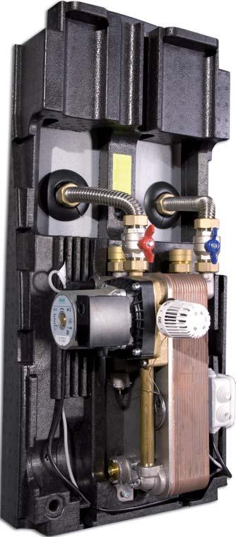
7 1.4 Design of the Fresh Water Station Flow switch Charge pump Temperature selector Electricity box Push-in connection for optional circulation unit Plate heat exchanger The above depicted picture is symbolic and can marginally differ from your Fresh Water Station. Manual Fresh Water Station FWS 20 / FWS 30. E & OE, subject to change without notice. 7


8 1.5 Scope of delivery Description Fresh Water Station Ready for plug-in installation Illustration Description Drilling plan Illustration Connection set, containing: - 2x fl exible hoses, length 205mm incl. swivel nuts - 4x fl at sealings Test certificate Mounting set, containing: - 1x socket wrench SW17-2x thread bolt M10x- 120mm - 4x washer A10,5-2x dowel S12, length 60mm - 6x hex-nut M10-2x stair bolt M10x- 120mm Warning notices Concerning overpressure and expansion equipment 8 Manual Fresh Water Station FWS 20 / FWS 30. E & OE, subject to change without notice.
9 1.6 Safety precautions The assembly, maintenance and cleaning must only be accomplished by qualifi ed technical professionals. The installation and operation must be performed according to regional regulations and laws, common practice and according to the directives of the local water utility. DIN 1988 Drinking water supply systems DIN 4708 Central heat- water-installations; terms and calculation-basis DIN EN Heating systems in buildings - design of water-based heating systems DIN 4753 Water heaters and water heating installations for drinking water and service water DIN 4757 Solar heating plants operating on organic heat transfer media; requirements relating to safe design and construction DIN German construction contract procedures - Systems for heating and central water heating DIN German construction contract procedures - Gas, water and sewage plumbing works inside of buildings DIN Contract procedures for buildings works - low-voltage installation and medium-voltage installation with nominal voltages up to including 36 kv DIN EN Thermal solar systems and their components VDE 0100 Low-voltages electrical installations VDE 0185 Lightning protection components (LPC) VDE 0190 Main equipotential bonding of electrical systems ÖNORM EN ISO 9488 Solar energy vocabulary (ISO 9488:1999) ÖNORM ENV Thermal solar systems and components - custom built systems - part 1: general requirements ÖNORM M7700 Solar energy - therms with defi nitions ÖNORM M7701 Solar energy installations; approximative calculation method for the dimensioning of fl at collectors in domestic hot water systems ÖNORM M7731 Solar heating systems for heating of water - requirements and tests Manual Fresh Water Station FWS 20 / FWS 30. E & OE, subject to change without notice. 9
10 2 Installation and initiation Before you install your new Fresh Water Station, please pay attention to the following points: Read chapter 1 and especially the warning notices in chapter 1.3. The Fresh Water Station is used to heat up tap water in connection with a buffer tank. Another use or installation is not intended. Do not connect the Fresh Water Station directly to any heat generator. The operation of this device is not allowed to persons with limited physical, sensory or intellectual abilities. Uninformed or unacquainted persons may operate the device only under the supervision or at the trained person s disposition. Replacements of electrical parts like the power cord must be conducted by a professional electrician. Installation and operation must be performed according to regional regulations and laws. 2.1 Installation The setting up and installation must be carried out by an approved professional crafts enterprise. It is also responsible for a proper installation and initiation. As a location for installation the device requires a frost-free room and the Fresh Water Station needs to be installed splash-proof and may only be operated at room temperatures under 40 C. 10 Manual Fresh Water Station FWS 20 / FWS 30. E & OE, subject to change without notice.
11 2.1.1 Installation on buffer tank Positioning on buffer tank socket wrench The mounting of the unit onto the buffer tank is carried out using the enclosed mounting material. 1. Screw the thread bolts approx. 10 mm into the threaded sleeves on the buffer tank. 2. Apply the counter nuts and fi x them. 3. Screw the hex-nuts on the bolt until the distance to the insulation is 40 mm. 4. Fit the Fresh Water Station onto the bolts and secure it with the washers and hex-huts. Caution! Tightening the screws too much can cause damage to the insulation! Manual Fresh Water Station FWS 20 / FWS 30. E & OE, subject to change without notice. 11
12 Installation of hot and cold water connections hot water connection cold water connection 5. Install the hot and cold water pipes according to the above depicted scheme and run the pipes through the upside of the insulation. Caution! Tighten the fl at-sealing connections only after sealing the piping. Avoid tightening torque and force effects on already installed parts and connections of the device at all costs! Additionally, check the tightening torques of the fl at-sealing swivel nuts (some loosening can happen during transport). 12 Manual Fresh Water Station FWS 20 / FWS 30. E & OE, subject to change without notice.
13 Installation of flexible hoses fl exible hose fl exible hose 6. Detach the ball valves from the Fresh Water Station, mount them according to Figure with fl at seals to the fl exible hoses and with fl at seals to the buffer tank. 7. Bend the fl exible hoses with mounted ball valves into the right position, according to Figure, and connect them with fl at seals to the Fresh Water Station. Caution! Bending of the fl exible hoses has to be done in such a way that there are no force effects onto the Fresh Water Station in working order. Manual Fresh Water Station FWS 20 / FWS 30. E & OE, subject to change without notice. 13
14 2.1.2 Installation on wall The mounting of the unit onto the wall is carried out using the enclosed mounting material. The piping from and to the buffer tank should be at least dimensioned in Cu28 to assure a fl ow rate of approx l/h. The length of piping ought to be as short as possible. 1. Transfer the drilling plan onto the wall and drill the marked holes with a 12mm drill approx. 7cm deep. 2. Insert the dowels into the holes and screw the stair bolts into the wall until the threads aren t visible any more. 3. Fit the Fresh Water Station onto the bolts and secure it with the washers and hex-huts. Caution! Tightening the screws too much can cause damage to the insulation! 2.2 Hydraulic connection Installation of the piping has to follow the instructions on the labeling (inside the upper part of the insulation) or the fi gure in the manual, respectively. The piping to the buffer tanks ought to be as short as possible! When using zinc coated pipes and fi ttings, take care of the installation sequence to avoid electrochemical corrosion. According to DIN 4753, part 1, a safety relief valve has to be included into the cold water supply pipe. The safety relief valve has to be dimensioned for a valving pressure that is in accordance with the allowed operating pressure. At a pressure of 6 bar and above, a pressure-reducing device has to be installed in the water pipe behind the water fl ow meter. A shutoff between the safety relief valve and the Fresh Water Station is not allowed. According to DIN 4753, the operation of the safety relief valve has to be tested regularly 1-2 times a month by bleeding the valve. The exhaust opening must not be closed or constricted. A state-of-the-technology water fi lter has to be installed and commissioned in the cold water 14 Manual Fresh Water Station FWS 20 / FWS 30. E & OE, subject to change without notice.
15 pipe. Additionally, it is advisable to install a drinking water expansion vessel depending on the faucets. At hot and cold water connections it is recommended to include rinsing ports. Tighten the fl at-sealing connections only after sealing the piping. The piping from and to the buffer tank should be at least dimensioned in Cu28 to assure a fl ow rate of approx l/h. The length of piping ought to be as short as possible to allow fast heating of the heat exchanger when opening a faucet. It is not allowed to install the device in gravitational heating systems! A de-aeration has to be included in the system at the highest point of the buffer circulation. Caution! Avoid tightening torque and force effects on already installed parts and connections of the device at all costs! 2.3 Electric connection The internal wiring of the electric parts is factory-provided. The connection to the electricity network (230 V/AC, 50Hz) happens with the connected power cord. Operations at the electrical parts of the device must be conducted according to regional regulations and laws. Caution! Before working on the electrical parts of the Fresh Water Station make sure to disconnect it from the electricity network! 2.4 Initiation The initiation must be carried out by an approved professional crafts enterprise. During the initiation process the unproblematic operation and leak-tightness of the whole installation, including the preinstalled connections, has to be tested. Slow opening of the ball valves at the entries and exits of the Fresh Water Station avoids pressure blows during the rinsing process. The fi lling and rinsing of the system needs to be continued until it is sure that the system is completely deaerated! Stream noises during operating the charge pump indicate that there is still air left in the system, which needs to be discharged over the pump. Before taking the installation into operation, it makes sense to rinse the tap water and heating water circuits with completely opened valves to remove sludge and other contaminations. This should avoid clogging of valves, heat exchangers Manual Fresh Water Station FWS 20 / FWS 30. E & OE, subject to change without notice. 15

16 and other parts of the installations. Due to vibrations during transports and thermal expansion the tightening torques of the fl at-sealing swivel nuts and piping have to be checked, after installation and initiation. 2.5 Mode of operation When hot water is tapped, the fl ow-switch turns on the charge pump. 2.6 Adjustment of tap water temperature Changing of the preset tap water temperature happens with the thermostatic temperature regulator. The most economical temperature range is between 45 and 55 C (equals factory setting). The temperature range can be changed, narrowed and fi xed with the red and blue Memory-Clips on the temperature regulator. Clockwise turning reduces the tap water temperature. To avoid thermal furring (see DIN 1988), an increase of temperature is not advisable. Buffer tank temperature recommendation: The buffer tank temperature should be at least 10K above the desired tap water temperature. 3 Usage of circulation unit The Fresh Water Station is prepared for an optional circulation unit. The circulation unit consists of a circulation pump with a Push-In connection, a ball valve and a circulation eccentric tappet. 16 Manual Fresh Water Station FWS 20 / FWS 30. E & OE, subject to change without notice.

17 3.1 Installation of circulation unit Remove splint-pin from the Push-In connection on the Fresh Water Station and remove blind cap. Push in the circulation unit as far as it will go into the Push-In connection and secure it with the splint-pin. blind cap splint-pin circulation unit splint-pin Advice! A rinsing port needs to be installed in the circulation pipes in front of the pump. Please make sure to read and understand the instructions enclosed in the circulation unit and the country-specifi c norms and regulations according drinking water! Caution! Like in all tap water circulation systems, suffi cient expansion and overpressure safety devices have to be included. Manual Fresh Water Station FWS 20 / FWS 30. E & OE, subject to change without notice. 17
.")

18 3.2 Operating modes of circulation unit Time-independent circulation Circuitry A The circulation pump is enabled by a short actuation of a warm water point of usage and deactivated by the integrated return-thermostat when the preset circulation return temperature is reached. During this mode of operation, the clock timer has no relevant function and must be set to Continuous Mode (ON). circulation pump cable The circulation pump is activated by the individually adjustable clock timer and deactivated when the preset circulation return temperature is reached. A therconnector load pump cable power supply cable fl ow switch cable printed circuit board Time-dependent circulation Circuitry B circulation pump cable connector load pump cable power supply cable fl ow switch cable printed circuit board 18 Manual Fresh Water Station FWS 20 / FWS 30. E & OE, subject to change without notice.
19 mostat takes care for the synchronized operation of the pump. There is no circulation beyond the preset times. The clock timer must be set to Timer Mode (TIMER). 3.3 Adjustment of return thermostat Set the arrow on the temperature setting switch with a screwdriver to the desired temperature. The starting temperature is 5 C below the set value. Caution! The preset circulation return temperature is 40 C. When changing this temperature, the thermostat has to be set 10 C below the hot water temperature! Manual Fresh Water Station FWS 20 / FWS 30. E & OE, subject to change without notice. 19
20 4. Malfunctions Prior to malfunction diagnostics, make sure that the following parameters are met: Flow temperature suffi cient, min. 55 C at max. 45 C tap water temperature. Faultless electrical connection 4.1 No hot water preparation Cause Relief Buffer tank not hot enough Increase temperature in buffer tank Charge pump doesn t convey buffer water Flow-Switch sends no signal to charge pump Electricity box broken (relay doesn t switch) Thermostatic temperature regulator misaligned Check water level in buffer tank (extraction of buffer water for the Fresh Water Station happens at the highest point of the tank). De-aerate buffer circuit and check system pressure. Check, if all shutoffs (fl ow and return, hot and cold water) are open. If not, open them. Check hydraulic resistance between buffer tank and Fresh Water Station and reduce it, if necessary. Check at initiation if the Fresh Water Station is correctly connected to the buffer circuit and drinking water system. Check Flow-Switch and electricity box. Replace broken charge pump. 1. Remove Flow-Switch 2. Clean Flow-Switch housing 3. Reintegrate Flow-Switch 4. If the Flow-Switch still sends no signal to the charge pump, replace Flow-Switch. 1. Check if power cord is connected to the electricity network. 2. Close shutoff valves 3. Remove Flow-Switch 4. Activate Flow-Switch manually. A working relay causes a switching noise in the electricity box. 5. If there is no switching noise, replace electricity box. Tap hot water Turn the thermostatic temperature regulator to max. temperature for a short time. If hot water is prepared again, set the regulator again. If no hot water is prepared, check the heat exchanger for thermal furring. Stop tapping hot water. 20 Manual Fresh Water Station FWS 20 / FWS 30. E & OE, subject to change without notice.
21 Thermal furring of plate heat exchanger Clean plate heat exchanger 4.2 No circulation Cause Relief Circulation pump doesn t 1. Check if shutoff at circulation connection is open. convey tap water 2. Circulation pump is not set properly. To check that, set the switch on the pump to ON. hydraulic resistance of tap water piping is too big for circulation pump If the pump conveys water, check settings on the pump and eventually switch to Timer Mode If no water is conveyed, replace circulation pump. Check dimensioning of tap water piping. 4.3 Circulation pump conveys time-independent Cause Relief Circulation unit was switched to time-independent Reconnect wiring of circulation pump for time-dependent circulation circulation 4.4 Constant circulation mode Cause Relief Circulation unit is not set 1. Check settings of circulation pump, check for possible false tempeproperly rature settings and the right timer setting 2. The set temperature on the circulation pump is not below the set temperature on the thermostatic temperature regulator. Adjust the temperature setting on the circulation pump. 4.5 Leaking of Fresh Water Station Cause Relief Fresh Water Station is leaking Check connection of pipes and sealings at the running device. Replace broken sealings. Manual Fresh Water Station FWS 20 / FWS 30. E & OE, subject to change without notice. 21
 G1\" IT G1\" IT Hot water (B) G1\" IT G1\" IT From system tank (C) G1\" ET G1\" ET To system tank (D) G1\" ET G1\" ET Circulation (E) G½\" IT G½\" IT Main")
 6 Optional circulation unit with pump and electronic return thermostat (suitable for timer or impulse mode) 22 Manual Fresh Water Station FWS 20 / FWS")
22 5 Technical data FWS 20 FWS 30 Dimensions Width 400 mm 400 mm Height 820 mm 820 mm Depth 290 mm 290 mm Insulation EPP EPP Weight 16 kg 20 kg Connections Fresh water (A) G1" IT G1" IT Hot water (B) G1" IT G1" IT From system tank (C) G1" ET G1" ET To system tank (D) G1" ET G1" ET Circulation (E) G½" IT G½" IT Main components 1 Check valve 2 Temperature selector 3 Heat exchanger 4 Charge pump 5 Push-in-connection for circulation unit (incl. blind cap) 6 Optional circulation unit with pump and electronic return thermostat (suitable for timer or impulse mode) 22 Manual Fresh Water Station FWS 20 / FWS 30. E & OE, subject to change without notice.
23 Output 20 l/min 30 l/min Min. operating temperature 2 C 2 C Max. operating temperature 95 C 95 C Max. operating pressure Fresh water 10 bar 10 bar Heating 3 bar 3 bar Charge Pump 230 V / 50 Hz 230 V / 50 Hz Rpm 2200 U/min 2200 U/min Power input 95 W 95 W Nominal current 0,4 A 0,4 A Circulation pump 230 V / 50 Hz 230 V / 50 Hz Power input 25 W 25 W Nominal current 0,1 A 0,1 A 6 Terms of guarantee The manufacturer issues a guarantee of 2 years from the invoice date on the device and its constituent parts. Without proper installation and use of the device the guarantee is void. Manual Fresh Water Station FWS 20 / FWS 30. E & OE, subject to change without notice. 23


24
Buffer Tank FWSS 1000 V7-RH
 Buffer Tank FWSS 1000 V7-RH Manual Art.-Nr.: 700119 (V1.0) Table of content 1. Preface 3 1.1 Usage 3 1.1.1 Usage example Fresh Water Station 3 2. Description 4 3. Warning notices 4 4. Design of the Fresh
Installation and instruction manual SOLAR STATION
 INSTALLATION AND INSTRUCTION MANUAL SOLAR STATION Installation and instruction manual SOLAR STATION SST 25-1E / SST25-2E EN April 2015 1 Table of contents Usage 3 Warranty 3 Safety instructions and symbol
Friwa Compact. Operating instructions EN
 Operating instructions EN Version 1.1 / Edition 09/2013 Contents 1 Key background information... 3 1.1 Limitation of liability... 3 1.2 Responsibilities of the operator... 3 1.3 Documentation... 3 1.3.1
Domestic Hot Water Tank
 Installation and Operating Manual Domestic Hot Water Tank WWKS 300 WWKS 500 EN For the professionals Read carefully before installation Table of Contents 1 Use............................. 3 2 Safety Instructions
Manual SLM50HE.
 Manual SLM50HE www.sonnenkraft.com www.sonnenkraft.com Table of Contents 1. General 3 1.1. Use 3 1.2. Application example 3 2. Description 4 3. Warning 4 4. Structure of the shift layer module 4 5. Safety
CIRCO 6 Solar Circulation Unit
 TECHNICAL INFORMATION / INSTALLATION INSTRUCTIONS CIRCO Solar Circulation Unit CIRCO Solar Circulation Unit in combination with the intelligent SUNGO controllers, it is the safe and reliable heart of a
Electronically controlled instantaneous water heater. MCX: 27300, and models. Installation instructions
 Electronically controlled instantaneous water heater MCX: 27300, 27400 and 27600 models Installation instructions These appliances deliver water not exceeding 50 ºC in accordance with AS3498. 1. Overview
Akva Vita TDP District heating flat station for direct heating and domestic hot water systems
 Akva Vita TDP District heating flat station for direct heating and domestic hot water systems Akva Vita TDP Table of contents Akva Vita TDP... 1 Table of contents... 1 Safety notes... 2 Delivery... 2 Transport
Electronically controlled instantaneous water heater. MCX: 27300, and models. Instructions for the user
 Electronically controlled instantaneous water heater MCX: 27300, 27400 and 27600 models Instructions for the user These appliances deliver water not exceeding 50 ºC in accordance with AS3498. 1. Overview
Electronically controlled instantaneous water heater. CEX 9-U: C models. Installation instructions
 Electronically controlled instantaneous water heater CEX 9-U: 27910-50 C models Installation instructions For 50 ºC models, the appliance delivers water not exceeding 50 ºC in accordance with AS3498. 1.
WH-TD20B3E5 WH-TD30B3E5
 Order No: PHAAM1004143C2 WH-TD20B3E5 WH-TD30B3E5 WARNING This service information is designed for experienced repair technicians only and is not designed for use by the general public. It does not contain
AOYG18LFC OUTDOOR UNIT INSTALLATION MANUAL INSTALLATION MANUAL. For authorized service personnel only. PART NO
 AOYG8LFC OUTDOOR UNIT INSTALLATION MANUAL INSTALLATION MANUAL For authorized service personnel only. English PART NO. 93778639 93778639_IM.indb /20/20 6:07:25 PM AIR CONDITIONER OUTDOOR UNIT INSTALLATION
VIESMANN. Installation instructions VITOCELL 300-B. for contractors. Vitocell 300-B Type EVBA-A. Dual mode DHW cylinder, 300 and 500 l
 Installation instructions for contractors VIESMANN Vitocell 300-B Type EVBA-A Dual mode DHW cylinder, 300 and 500 l VITOCELL 300-B 1/2017 Dispose after installation. Safety instructions Please follow these
TIDALWAVE I/G POOL PUMP INSTRUCTION MANUAL
 TIDALWAVE I/G POOL PUMP INSTRUCTION MANUAL READ THIS MANUAL CAREFULLY BEFORE USING YOUR PUMP 88 PUMP PARTS BREAKDOWN REF # Order # Mfr # Description 1 NEP4 AC 348 Lid Knobs NEP AC 380 Strainer Lid 3 NEP6
ELECTRIC BOILERS FOR CENTRAL HEATING
 ELECTRIC BOILERS FOR CENTRAL HEATING TermoMax INSTRUCTIONS FOR INSTALLATION INSTRUCTIONS FOR INSTALLATION We reserve the right of alternations WE ARE NOT LIABLE FOR DAMAGES RESULTING FROM NON- OBSERVING
Akva Vita Instantaneous water heater
 Akva Vita Instantaneous water heater Akva Vita Table of Contents Akva Vita... 1 Table of Contents... 1 Safety notes... 2 Delivery... 2 Transport and storage... 2 Mounting... 3 Pipes connections... 4 Electrical
Model NFF Iron, Manganese, Hydrogen Sulfide Reduction
 Super Filter Model NFF Iron, Manganese, Hydrogen Sulfide Reduction Operating and Maintenance Manual Page 1 of this manual contains operating conditions. 57055 9/07 Enjoy clean, stain-free laundry and dishes...
Akva Vita TDP-F District heating flat station for direct heating and domestic hot water systems
 Akva Vita TDP-F District heating flat station for direct heating and domestic hot water systems Akva Vita TDP-F Table of contents Akva Vita TDP-F...1 Table of contents...1 Safety notes...2 Delivery...2
Installation & Service Guide
 Reverse Osmosis Ontario Soft Water.ca Kitchener, Canada 519-579-0500 Installation & Service Guide Pentair 75 gpd Encapsulated Membrane System Standard System 75gpd Membrane Your New Reverse Osmosis System
Technical information for installation and operation
 Technical information for installation and operation PR 24002.65 12-04-2016 Subject to technical modifications LogoFresh 100 & 120 fresh water station Electronically controlled GB Meibes System-Technik
REVERSE OSMOSIS DRINKING WATER SYSTEM
 REVERSE OSMOSIS DRINKING WATER SYSTEM 12/12 1 Please fill out the following information at the time of installation. Save for future reference. Model: Sierra NS-1N30-00 Date Code: Install Date: Sold by:
WATER FILTRATION SYSTEM (USF3) OWNER S MANUAL
 OWNER S MANUAL") WATER FILTRATION SYSTEM (USF3) OWNER S MANUAL 1 INTRODUCTION Congratulations on choosing Permatech to improve the quality of your water. You will immediately begin to notice the numerous benefits of having
WATER FILTRATION SYSTEM (USF3) OWNER S MANUAL 1 INTRODUCTION Congratulations on choosing Permatech to improve the quality of your water. You will immediately begin to notice the numerous benefits of having
Installation and Operation Instructions Domestic hot water module FriwaMini with circulation - DN 15
 PAW GmbH & Co.KG Böcklerstr. 11, D-31789 Hameln, Germany Phone: +49-5151-9856-0, Fax: +49-5151-9856-98 E-mail: info@paw.eu, Web: www.paw.eu Installation and Operation Instructions Domestic hot water module
OK, OKA, OKAF; ELD; ELDM; ELH; OKC; SC; SCA; SCAF; OK-LN; OKA-LN; OKAF-LN.
 INSTALLATION, OPERATION & SERVICE MANUAL FOR COOLER TYPES OK, OKA, OKAF; ELD; ELDM; ELH; OKC; SC; SCA; SCAF; OK-LN; OKA-LN; OKAF-LN. 1. Introduction This manual is a guide for the installation, maintenance
541D19 SERIES. Technical Manual. A Division of Aquion Partners L.P.
 541D19 SERIES Technical Manual A Division of Aquion Partners L.P. Table of Contents Introduction... Page 1 Technical Specifications... Page 2 Flow Diagrams... Page 3 Injector & Flow Control Selection Injector...
LYRA 1000 VVS Installation and Operation Manual LYRA 1000 VVS THERMAL STORE LYRA 1000 VVS
 www.regulus.eu LYRA 1000 VVS Installation and Operation Manual LYRA 1000 VVS THERMAL STORE EN LYRA 1000 VVS CONTENTS 1 Description... 3 1.1 Models... 3 1.2 Tank protection... 3 1.3 Thermal insulation...
Thermostatic valves with radiator connection systems
 Multilux Eclipse Thermostatic valves with radiator connection systems with two-point connection for two-pipe heating systems, with automatic flow limitation IMI HEIMEIER / Thermostatic heads and Radiator
General Terms and Conditions of Connection and Warranty
 General Terms and Conditions of Connection and Warranty Buffer Tank Please pass on to the user. Dear customer! You have chosen a buffer tank produced by our company for water heating. We thank you for
PL-004-SS. * Proper water pressure is required for simultaneous operations
 PL-004-SS Features - Stunning stylish European inspired design - Elegant durable stainless steel frame construction - 4 stage shower functions (Rainfall, Waterfall, Massage Spray, Hand Shower) - Simultaneous
Operating Guide. Termix Compact 28 VX-FI / HWP / HWS. 1.0 Table of Contents. 1.0 Table of Contents
 1.0 Table of Contents 1.0 Table of Contents... 1........................................................................ 2 2.0 Functional description... 3 3.0 Safety notes... 4 3.1 Safety Notes general............................................
Cabinet Non-Electric Water Softener
 Cabinet Non-Electric Water Softener INSTALLATION MANUAL Table of Contents 1. Parts 3 2. Precautions 4 3. Installation 4 4. Settings 6 5. Start-up 7 6. Performance Data Sheet 10 The CABINET NON-ELECTRIC
INSTALLATION AND OPERATION MANUAL
 INSTALLATION AND OPERATION MANUAL Flow water heaters type PERFECT MIX 3,5-4,0-4,5-5,0-5,5 kw 1. Purpose and description Flow water heaters type PERFECT MIX 3.5-5.5 kw are intended for supplying hot water
HW 22 District heating substation for indirect heating and domestic hot water systems
 HW 22 District heating substation for indirect heating and domestic hot water systems HW 22 Table of contents HW 22... 1 Table of contents... 1 Safety notes... 2 Delivery... 2 Transport and storage...
Electronically controlled instantaneous water heater. DEX: C models. Instructions for the user
 Electronically controlled instantaneous water heater DEX: 27930-50 C models Instructions for the user For 50 ºC models, the appliance delivers water not exceeding 50 ºC in accordance with AS3498. MADE
Electronically controlled instantaneous water heater CEX 9. CEX9: C models. Instructions for the user
 Electronically controlled instantaneous water heater CEX 9 CEX9: 27900-50 C models Instructions for the user For 50 ºC models, the appliance delivers water not exceeding 50 ºC in accordance with AS3498.
Installation Instructions
 Installation Instructions KFN 9855 ide en - CA Installation, repair and maintenance work should be performed by a Miele authorized service technician in accordance with national and local safety regulations
SUN EQUINOX HEATING SYSTEMS
 SUN EQUINOX HEATING SYSTEMS HIGH-EFFICIENCY HOT WATER SOLUTIONS INSTALLATION & OPERATION MANUAL Production Number: Customer Contact Information Other Resources 260-65-5605 http://www.solarusagenow.com
FUN I / FUN U FUN I MCP / FUN U MCP FUN V / FUN V MCP
 OPERATION INSTRUCTIONS MANUAL DUCTED FAN COILS UNIT FUN I / FUN U FUN I MCP / FUN U MCP FUN V / FUN V MCP 1 CONTENTS 1. GENERAL... 3 2. INSTALLATION... 4 3. AIR CONNECTIONS... 5 4. WATER CONNECTIONS...
OPERATING AND MAINTENANCE MANUAL
 HYDROFILL Hydronic water treatment filling units Copyright 2016 Caleffi OPERATING AND MAINTENANCE MANUAL NA10439 www.caleffi.com NA5709 series Function HYDROFILL is a water treatment fi lling unit that
Spectrum TM. Installation, Service & Operation Manual O FLO. SoftH 2. Water Softener. Table of Contents
 Installation, Service & Operation Manual SoftH 2 O FLO Water Softener Table of Contents 1. Description & Equipment Adjustments p.2 2. Components, Features & Functions p.3 3. Valve User Interface p.4 4.
VIESMANN. Installation instructions VITOCELL 300-V/W. for contractors. Vitocell 300-V/W Type EVIA-A
 Installation instructions for contractors VIESMNN Vitocell 300-V/W Type EVI- DHW cylinder with internal indirect coil 160 to 500 l VITOCELL 300-V/W 3/2017 Dispose after installation. Safety instructions
USER S MANUAL ATH WH220
 USER S MANUAL ATH WH220 INDEX INTRODUCTION... - 3 - General information s... - 3 - Description of pneumatic jack... - 4 - Operation of jack... - 5 - Technical data... - 6 - Dimension drawing... - 6 - INSTALLATION...
CHAMPION PUMP OWNER S MANUAL
 CHAMPION PUMP OWNER S MANUAL IMPORTANT SAFETY INSTRUCTIONS READ AND FOLLOW ALL INSTRUCTIONS SAVE THESE INSTRUCTIONS WARNING: Before installing this product, read and follow all warning notices and instructions
Installer manual AG-AA10. Air/air heat pump IHB GB AG-AA10-30 AG-AA10-40/50
 -30 Installer manual Air/air heat pump -40/50 IHB GB 1516-1 331554 Table of Contents 1 Important information 2 5 Installation 7 Safety information 2 Model combinations 7 Read before starting the installation
WSK300 Multifunction Wall Control
 WSK300 Multifunction Installation & Operating Instructions WARNING Hearth & Home Technologies disclaims any responsibility for, and the warranty will be voided by, the following actions: Installation and
Handshower, Hose & Handshower Accessories
 INSTALLATION INSTRUCTIONS P21650, P21660, P24452, P24453, P24454, P24456, P24743, P24745, P24746, P24761, P24843 1188577-2-F 2014 KALLISTA 1 of 5 THANK YOU FOR CHOOSING KALLISTA We appreciate your commitment
Operating Guide. Termix Solar A+/B+ 1.0 Table of Contents. 1.0 Table of Contents
 1.0 Table of Contents 1.0 Table of Contents... 1........................................................................ 2 2.0 Functional description... 3 3.0 Safety notes... 4 3.1 Safety Notes general............................................
ASSEMBLY INSTRUCTIONS FOR THE PUMP AND CONTROL UNIT ZPS 18a-01
 ASSEMBLY INSTRUCTIONS FOR THE PUMP AND CONTROL UNIT ZPS 18a-01 1. Use and construction of the pump and control unit The pump and control unit is designed to work with solar collectors in systems with required
INSTALLATION AND OPERATING INSTRUCTIONS General operating instructions for sample gas conditioner Model: MAK 6
 List of contents 1.0 Uses 2.0 Technical data 2.1 Operating data 2.2 Construction and installation 2.3 Climatic load 2.4 Power supply 3.0 Function and design 3.1 General comments 3.2 Design 3.3 Performance
WINDOW TYPE ROOM AIR CONDITIONER OPERATION AND INSTALLATION MANUAL
 MODEL RA-0LDF RA-3LDF WINDOW TYPE ROOM AIR CONDITIONER OPERATION AND INSTALLATION MANUAL AIR DEFLECTORS VERTICAL DEFLECTORS Vertical de ectors at both sides of outlets can be set to either auto-swing or
For reversed flow direction. Thermostatic Radiator Valves Thermostatic valve body with and without presetting
 For reversed flow direction Thermostatic Radiator Valves Thermostatic valve body with and without presetting IMI HEIMEIER / Thermostatic Heads & Radiator Valves / For reversed flow direction For reversed
INSTANT HOT WATER RECIRCULATING SYSTEM
 INSTANT HOT WATER RECIRCULATING SYSTEM INSTALLATION AND OPERATING INSTRUCTIONS Save manual for future reference MODEL 500800 Pump and Comfort Valve CS VW 12" Supply Line and Adapters MH26400 65GM U P C
FAVORIT34502VIO. EN User Manual
 FAVORIT34502VIO EN User Manual 2 www.aeg.com CONTENTS 1. SAFETY INFORMATION...3 2. SAFETY INSTRUCTIONS... 4 3. PRODUCT DESCRIPTION... 6 4. CONTROL PANEL...6 5. PROGRAMMES... 7 6. SETTINGS... 8 7. BEFORE
Manual and installation instructions. Function. Operating phase
 LADDOMAT M120 Manual and installation instructions Thermal layering Function Thanks to its design and control features, the Laddomat M120 means optimal thermal layering in storage tanks, with a low and
TT /97 WARNING WARNING WARNING INSTALLATION INSTRUCTIONS
 TT-116 2/97 INSTALLATION INSTRUCTIONS Original Issue Date: 2/97 Model: 900/1000 kw Market: Industrial Subject: Block Heater Kits PA-28648, PA-28648-SD The block heater kit heats engine coolant, making
Installation manual Operating instructions
 WIKORA GmbH Friedrichstr. 9 89568 Hermaringen Phone: (07322) 9605-0 Fax: (07322) 9605-30 email: contact@wikora.de Installation manual Operating instructions DHW storage tank UNO/DUO/H/WPSOL Installation
Installation instructions for condenser tumble dryer DOMESTIC. Dear Customer,
 Dear Customer, Read these instructions carefully and completely before you install the machine. The installation should be carried out by a qualified person who is familiar with all local codes and ordinances
Zip InLine. Models CEX-O & CEX-U Issued August Installation, Maintenance and User Instructions
 CEX cover qxd:varipoint cover qxd 17/10/11 16:41 Page 1 Installation, Maintenance and User Instructions Zip InLine Electronically Controlled Instantaneous Water Heaters Models CEX-O & CEX-U Issued August
FSW300 Series Flow Switch
 . FSW300 Series Flow Switch - 2 - Series FSW300 Series FSW300 Table of contents page 0 About this operating manual... 4 1 Device description... 5 1.1 Intended use... 5 1.1.1 Reed contact - Switching of
Instructions for installation and use Akva Lux II VX substations 1. Contents
 Akva Lux II VX thermostatic control Akva Lux II VX thermostatic control, and optional junction box + zone valve Akva Lux II VX (ECL 110) Akva Lux II VX HWP (ECL210) Akva Lux II VX H2WP (ECL 210) 1. Contents
SHOWER SOFTENER-CEASA 1
 SHOWER SOFTENER-CEASA 1 Application: The product is mainly used for shower water softening, but can also be used for floor heating, beauty salons, hairdressing salons, washing machines etc. The softener
Pro-Clean Stratified Tank scope of delivery:
 Foreword Hearty congratulations on your purchase of a product from TiSUN! We vouch for the high quality and long service life of our products with our name. Only licensed specialized companies that have
Installation Instructions Ceiling Kit
 Installation Instructions Ceiling Kit Model No. ENGLISH FRANÇAIS ESPAÑOL * Above illustration is shown in combination of this product and optional projector. Thank you for purchasing this Panasonic product.
IMPORTANT SAFETY INFORMATION READ ALL...
 INSTALLATION and SERVICE MANUAL HOUSEPURE MODELS HP03 and HP04 736-0137 Table of Contents IMPORTANT SAFETY INFORMATION READ ALL... 3 P/N 41482 Rev A 06/04 INSTRUCTIONS BEFORE USING... 3 FEEDWATER... 4
Eclipse. Thermostatic Radiator Valves Thermostatic radiator valve with automatic flow limitation
 Eclipse Adaptative Flow Control Thermostatic Radiator Valves Thermostatic radiator valve with automatic flow limitation IMI HEIMEIER / Thermostatic Heads & Radiator Valves / Eclipse Eclipse The thermostatic
ECONO FLO VSA 165 VARIABLE SPEED PUMP OWNER S MANUAL
 ECONO FLO VSA 165 VARIABLE SPEED PUMP OWNER S MANUAL IMPORTANT SAFETY INSTRUCTIONS READ AND FOLLOW ALL INSTRUCTIONS SAVE THESE INSTRUCTIONS WARNING: Before installing this product, read and follow all
OPERATION AND INSTALLATION
 Tankless Electric Water Heater with electronic temperature control Residential Use F C Blinking: maximum power, less than set point temp. Steady: unit operating Off: unit off Tankless Electric Water Heater
Laing Thermotech. Autocirc The Instant Hot Water Pump Models E1-BCANCT1W-06 and E1-BCANRT1W. Installation & Operating Manual
 Installation & Operating Manual Please read this manual carefully before attempting to install, operate or maintain the product described. Failure to comply with the information provided in this manual
Installation instructions for vented tumble dryer DOMESTIC. Dear Customer,
 Dear Customer, Read these instructions carefully and completely before you install the machine. The installation should be carried out by a qualified person who is familiar with all local codes and ordinances
JOHN DEERE GATOR HPX/XUV 2 PASSENGER HEATER INSTALLATION INSTRUCTIONS (p/n: 9PH20S30)
") P. 1 of 12 JOHN DEERE GATOR HPX/XUV 2 PASSENGER HEATER INSTALLATION INSTRUCTIONS (p/n: 9PH20S30) Item: Qty: Description: 1 2 1 x 1 x 5/8 Tee Fitting 2 2 Plastic Snap-in Hose Grommet 3 4 1-1/2" Hose Clamps
P. 1 of 12 JOHN DEERE GATOR HPX/XUV 2 PASSENGER HEATER INSTALLATION INSTRUCTIONS (p/n: 9PH20S30) Item: Qty: Description: 1 2 1 x 1 x 5/8 Tee Fitting 2 2 Plastic Snap-in Hose Grommet 3 4 1-1/2" Hose Clamps
Installation and operation instructions Solar stations SolarBloC midi Premium DN 20 SolarBloC maxi Premium DN 25
 PAW GmbH & Co. KG Böcklerstr. 11, D-31789 Hameln, Germany Phone: +49-5151-9856-0, Fax: +49-5151-9856-98 E-mail: info@paw.eu, Web: www.paw.eu Installation and operation instructions Solar stations SolarBloC
Installation & Service Manual
 Installation & Service Manual Table of Contents Unpacking & Inspection... 2 Basic Guidelines... 2 Specifications... 3 Before Starting Installation Where to install the filter... 4 Tools, pipe, fittings
Dishwasher installation guide
 DW80H9950US-00151A-06_EN_150216.indd 1 DW80H99* Series DW80J99* Series DW80J75* Series Dishwasher installation guide STOP These installation instructions are intended for use by qualified installers. If
SMF PUMP OWNER S MANUAL
 SMF PUMP OWNER S MANUAL IMPORTANT SAFETY INSTRUCTIONS READ AND FOLLOW ALL INSTRUCTIONS SAVE THESE INSTRUCTIONS WARNING: Before installing this product, read and follow all warning notices and instructions
- 1 - Updated on 18 March, 2010
 - 1 - Updated on 18 March, 2010 TABLE OF CONTENTS 1. SPECIFICATION & PARTS IDENTIFICATION...3 2. OPERATION & FUNCTION OF PARTS...4, 5 A. Cooling Operation B. Heating Operation C. Function of Parts 3. LOCATION
ASSEMBLY and INSTALLATION INSTRUCTIONS. Pipe wrench Ratchet 3/8 socket 9/16 socket 11/16 socket 3/16 Allen key 3/32 Allen key 9/64 Allen key
 ASSEMBLY and INSTALLATION INSTRUCTIONS Gas Conversion Kit Tube Heaters View these instructions online at www.lbwhite.com Kit Contents: DESCRIPTION QTY. Instructions 1 Burner orifi ce 1 Manifold pipe 1
BUILT-IN DISHWASHER INSTALLATION INSTRUCTIONS
 BUILT-IN DISHWASHER INSTALLATION INSTRUCTIONS PLEASE READ COMPLETE INSTRUCTIONS BEFORE YOU BEGIN LEAVE INSTALLATION INSTRUCTIONS AND USER'S GUIDE WITH OWNER ALL ELECTRIC WIRING AND PLUMBING MUST BE DONE
ECONO FLO 2.7HP VARIABLE SPEED PUMP OWNER S MANUAL
 ECONO FLO 2.7HP VARIABLE SPEED PUMP OWNER S MANUAL IMPORTANT SAFETY INSTRUCTIONS READ AND FOLLOW ALL INSTRUCTIONS SAVE THESE INSTRUCTIONS WARNING: Before installing this product, read and follow all warning
APPENDIX 4. Thank you for choosing the Biomega BioClave steam sterilizer. HYDRAULIC DRAWING
 Thank you for choosing the Biomega BioClave steam sterilizer. Your steam sterilizer has been CE certified and designed with durability, reliability, and safety in mind. It is your responsibility to install
Installation Manual SPA BROADWAY MAXI
 Installation Manual SPA BROADWAY MAXI 1 2 INDICE 1. RECEIVING THE EQUIPMENT... 4 2. PREPARING THE PLACE FOR THE INSTALLATION... 4 3. POSITIONING THE SPA... 7 4. ELECTRICAL CONNECTIONS... 7 4.1. Earth connection...
Akva Lux TDP-F District heating flat station for direct heating and domestic hot water systems
 Akva Lux TDP-F District heating flat station for direct heating and domestic hot water systems Akva Lux TDP-F Table of contents Akva Lux TDP-F... 1 Table of contents... 1 Safety notes... 2 Delivery...
LS Condensate Removal Pump INSTRUCTION MANUAL REVISION A
 LS Condensate Removal Pump INSTRUCTION MANUAL 6-71-075-115 REVISION A CAUTION: Combustible liquids may not be pumped! The condensate pump may not be run dry, as this can destroy the bearings in a very
Eclipse F. Thermostatic Radiator Valves Thermostatic radiator valve with automatic flow limitation
 Eclipse F Adaptative Flow Control Thermostatic Radiator Valves Thermostatic radiator valve with automatic flow limitation IMI HEIMEIER / Thermostatic Heads & Radiator Valves / Eclipse F Eclipse F The thermostatic
SCHWAN INSTALLATION GUIDE
 SCHWAN INSTALLATION GUIDE For Schwan Versatap SC52E Instant Hot Cold Filtered Water FOR SERVICE OR ASSISTANCE CALL MERQUIP ON 0800 636 0 636. Schwan recommends that a qualified tradesperson installs your
INSTALLATION GUIDE. soft duomatik evoline
 INSTALLATION GUIDE soft duomatik evoline Before introduction of the softener the installation guide has to be read carefully. For any disturbances cause by disregarding the instructions evo-water doesn
INSTALLATION INSTRUCTIONS
 INSTALLATION INSTRUCTIONS Accessory Application Publications No. ENGINE BLOCK P/N 08T44-SVB-100 2011 CIVIC 4-DOOR Si All 44405 Issue Date AUG 2010 PARTS LIST Engine block heater Aluminum washer Heater
Installation Manual. SiCOMS. Oil mist Concentration monitoring Diesel- and `-Version. Part No.: Release: (revision )
") SiCOMS Oil mist Concentration monitoring Diesel- and `-Version Part No.: 2 900 00 00001 Release: 130114 (revision 180209) Contents 1. Safety instructions... 1 1.1. Safety instructions...1 2. Standards
SiCOMS Oil mist Concentration monitoring Diesel- and `-Version Part No.: 2 900 00 00001 Release: 130114 (revision 180209) Contents 1. Safety instructions... 1 1.1. Safety instructions...1 2. Standards
Aquience 1200/1500 R
 Aquience 1200/1500 R Congratulations, you have purchased one of the fi nest quality aquariums available. This product will give you many years of excellent service when installed and maintained correctly.
Flow Factor ~
 Flow Factor ~ 216-765-4231 The DHC-E series is tested and certified by WQA against NSF/ANSI 372 for lead free compliance. STIEBEL ELTRON Inc. 17 West Street West Hatfield MA 01088 Tel. 413-247-3380 Fax
INSTALLATION MANUAL GUTHD2. Universal Two Way Digital Thermostatic Valve for Shower Systems
 INSTALLATION MANUAL GUTHD2 Universal Two Way Digital Thermostatic Valve for Shower Systems IMPORTANT: To ensure this product is installed properly, you must read and follow these guidelines. The owner/
FDT11 FDT15 FDT18. DUCTED TYPE SPLIT SYSTEMS (3 Phase, Fixed Speed)
") OPERA TION & I NSTALLAT I O N FDT11 FDT15 FDT18 MANUAL DUCTED TYPE SPLIT SYSTEMS (3 Phase, Fixed Speed) Read this operating & installation instruction carefully and keep it for future reference DUCTED
OPERA TION & I NSTALLAT I O N FDT11 FDT15 FDT18 MANUAL DUCTED TYPE SPLIT SYSTEMS (3 Phase, Fixed Speed) Read this operating & installation instruction carefully and keep it for future reference DUCTED
User instructions DHP-AT
 User instructions DHP-AT VUGFC202 If these instructions are not followed during installation and service, Danfoss A/S liability according to the applicable warranty is not binding. Danfoss A/S retains
Instruction Manual - Anti-Siphon Ejector Chlorine & Sulfur Dioxide 500 PPD (10 kg/h) Maximum Capacity
 Maximum Capacity") - Anti-Siphon Ejector Chlorine & Sulfur Dioxide 500 PPD (10 kg/h) Maximum Capacity 100 PPD (2 kg/h) Chlorine or Sulfur Dioxide 250 & 500 PPD (5 & 10 kg/h) Chlorine or Sulfur Dioxide Anti-Siphon Ejector
- Anti-Siphon Ejector Chlorine & Sulfur Dioxide 500 PPD (10 kg/h) Maximum Capacity 100 PPD (2 kg/h) Chlorine or Sulfur Dioxide 250 & 500 PPD (5 & 10 kg/h) Chlorine or Sulfur Dioxide Anti-Siphon Ejector
TECHNICAL INFORMATION Touchtronic Clothes Dryers
 TECHNICAL INFORMATION Touchtronic Clothes Dryers Includes: T1302, T1303, T1322, T1329ci T1403 & T1405 2004 Miele This page intentionally left blank. Table of Contents GENERAL INFORMATION A. Warning and
FAVORIT 34502VI0. EN User manual
 FAVORIT 34502VI0 EN User manual 2 www.aeg.com CONTENTS 1. SAFETY INSTRUCTIONS...................................................... 3 2. PRODUCT DESCRIPTION.....................................................
HX-30/40 and HX-30/40 S Glass and Dishwashers
 HX-30/40 and HX-30/40 S Glass and Dishwashers INSTALLATION OPERATION VERSION 18/01/00 2 Installation and Operation Instructions for Model HX-30/40 and HX-30/40 S (with built-in softener) Content Page 1
SC250X FLOOR GRINDER OPERATIONS MANUAL
 Unit 4/1 Rocklea Drive Port Melbourne Vic 3207 1300 109 108 www.traxxcp.com.au SC250X FLOOR GRINDER OPERATIONS MANUAL The contents of this Operations Manual are the copyright of the publisher and may not
The Extraordinaire OWNER S MANUAL. Orbital Ceiling Fan. Model No. OF110** READ AND SAVE THESE INSTRUCTIONS. Net Weight 14.5 lbs. or 6.59 kg.
 The Extraordinaire Orbital Fan WARNING: Support Directly From Building Structure Net Weight 14.5 lbs. or 6.59 kg. Model No. OF110** OWNER S MANUAL READ AND SAVE THESE INSTRUCTIONS Important Safety Instructions
Electrical Mini Tank Water Heater anual, and Warranty nformation
 Electrical Mini Tank Water Heater Installation uide, ser anual, and Warranty nformation Electrical Mini Tank Water Heater 2.6 Gals 2.6 IMPORTANT SAFETY INFORMATION A SAFETY VALVE MUST BE USED FOR PROPER
Commissioning a Solar Thermal Installation
 OPERATING INSTRUCTIONS Wagner& Co Commissioning a Solar Thermal Installation Contents. Solar Circuit... 2. Commissioning... 3 3. Service Information... 4. Maintenance.... Solar Circuit Components Pipework