FUN I / FUN U FUN I MCP / FUN U MCP FUN V / FUN V MCP
|
|
|
- Cecily Jones
- 5 years ago
- Views:
Transcription


1 OPERATION INSTRUCTIONS MANUAL DUCTED FAN COILS UNIT FUN I / FUN U FUN I MCP / FUN U MCP FUN V / FUN V MCP 1
2 CONTENTS 1. GENERAL INSTALLATION AIR CONNECTIONS WATER CONNECTIONS ELECTRICAL CONNECTIONS DIMENTION & WEIGHT MAINTENANCE SPARES
3 1. GENERAL Installation of the unit Read carefully this manual before to start installation operations. This unit comply with low voltage directive CEE/73/23 and electromagnetic compatibility CEE/89/336. Installation is to be done by qualified and trained technicians installers. Check all local safety regulations. Control earth electrical connection. Check that available voltage and electrical frequency are complying with stamped indications of the unit nameplate. Check that general electrical alimentation is correctly protected against over-voltage, shortcircuit and electrocution. Once installation is effective, check all functions are correctly running and explain the use and safety details to the user. Receiving and storage of goods When receiving a shipment, check the conditions of the goods and report immediately any damage in transit to the shipping company and to the manufacturer. Check that type and number of units are strictly conforming to the order acknowledgement bill or transport bill. If not, report immediately to the shipping company and to the manufacturer. Store the unit in dry (< 80% hygrometry) and clean area. Assure no vibrations or chocks. If storage period exceed 1 year, check and control the unit before installation. Do not place heavy articles on the unit. Unpack the unit with precautions and prevent any risk. Location Use this unit only for application which has been defined by technical office and/or manufacturer. WARNING : Before any kind of work on the unit or access to internal components, switch off the main electrical power supply. Keep this unit out of frozen area. Keep this unit out of flammable gases area. Keep this unit out of corrosive area (i.e. marine environment). Maximum air supply temperature must not exceed 60 C. Manufacturer recommends maintaining air supply < 37 C. Failure to take proper accounts of the above advice and unauthorized modification of the electrical connections will render the manufacturer warranty of the product null and void. In any case of dysfunction, switch off the unit and contact our after sale services. Packing and pallet should be recycled according to the local regulations. Location to avoid : Areas near excessive heat sources. Wet areas and /or where the unit could be in contact with water. Recommended locations : The easiest place for installer; Take care sufficient clearance around the unit allow dismantling of components (filter, coils, fan). Condensing water pipe can reach a sewer pipeline. WARNING : The water condensing pipe must have a continuous down slope - minimum 2%. Connection to the sewer pipeline must be done with a siphon. Siphon is to be dimensioned according to the condensing water flow. Cold water feed pipe must be fully insulated to prevent any condensing water drop. 3
4 2. INSTALLATION UNPACKING Check that type and number of units are strictly conforming to the order acknowledgement bill or transport bill. If not, report immediately to the shipping company and to the manufacturer. check the conditions of the goods and report immediately any damage in transit to the shipping company and to the manufacturer. Check indications on the nameplate. Make sure the unit are as close as possible to the final installation site before to unpack. Do not handle the unit with the condensing trolley and/or exchanger collector and/or condensate pump and/or spigots. AREA FOR LOCATION Take care sufficient clearances around the unit allow easy dismantling of components (filter, coils, fan). If necessary proceed to test of components extraction. Electrical and hydraulic connections are located on the same lateral face of the unit (unless otherwise specified on order, the standard delivery is the right face). INSTALLATION AT CEILING The supporting structure must be able to carry the unit weight and prevent deformation, breaks or vibrations during the operation. Use a hydraulic or electrical special lift and a folding ladder to facilitate this task. Remove all debris and construction material from the ducts in order to prevent any damage to the unit at start up. Mark the position of the threaded hangers (not supplied) on the ceiling (you may use a drilling template for more accurate positioning or if there are numerous units to settle). Recommended hangers diameter is 8 mm. The method of fixing the hangers depends on the ceiling type. When moving the unit, do not use water pipe, condensate trolley, valves or condensing pump to lift it. Once the threaded hangers are fixed to the ceiling, tighten the 4 nuts. Leave a space between the the ceiling and the unit in order to adjust finally when the unit has been leveled. With an horizontal bubble level indicators adjust the hangers nuts so that the unit is inclined 5 mm towards the condensate drain pan. In the other direction, the unit must be perfectly horizontal. Condensate water exhaust pipe. The condensate drain pan has a 14 mm outside diameter. A flexible pipe with a 16 mm or 25 mm inside diameter can be used (not supplied). The condensate drain pipe shall have a constant down slope of 2 % (2 cm/m). Install a 50 mm (minimum) siphon to prevent gases and odors from flowing back into ceiling void. If this constant fall of condensate drain pipe cannot be done, i twill be necessary to use a condensate pump (contact our service). We recommend to insulate the condensate drain pipe with 5 to 10 mm neoprene or polyurethane. If several units are connected to a common collector, follow this connection sketch : Before operating the unit, ensure that the water flows into the internal condensate drain pan by pouring 1 or liters of water into it. If there is a condensate pump check start and stop. In case of problems, check the pipe slope and control obstructions. 4


5 3. AIR DUCT CONNECTION Number of Airclip spigots FUN 40 I/U FUN 50/60 I/U FUN 50/60 V Inlet Min Diam. 200 Max Outlet Min max Diam. 125 Fresh air Number of Airclip spigots FUN 80/90 I FUN 80/90 U Inlet Min 2 1 Diam. 200 Max 5 2 Outlet Min 2 2 max 5 4 Diam. 125 Fresh air 1 1 5

6 Number of Airclip spigots FUN 120 I Inlet Min 3 Diam. 200 Max 6 Outlet Min 3 max 6 Diam. 125 Fresh air 1 The ducted fan coil FUN is monobloc, and therefore includes at suction and discharge the plenums functions. The installer is free to select the duct networks he wishes for each particular cases of installation. The number of spigots and their position must comply with above sketches. The plastic spigots (so called «AIRCLIP») are delivered not fitted on the units. The Airclip spigots are common to all size of FUN and can be fitted at inlet as well as outlet. 5 Before to fit the Airclip spigot, remove the relevant caps of the structure. These caps can be easily removedwith a mallet or by making lever with a turn-screw in order to break the small metallic clips. Check that inside insulation has been properly removed together with the caps. If necessary clear the duct opening with a cutter and remove all insulations debris. If there is no duct tat suction (free inlet air entrance), it is recommended to take off all inlet caps. When caps have been removed, settled the Airclip spigot. The fastener must lock the spigot and press the O-ring. The fastening is quite resistant. Now, if Airclip spigot is to be removed for any reason the only solution is to break it. Airclip spigot can be settled before to put the fan coil at ceiling it is easier. Connect the air ducts. In order to guarantee good air tightness, the duct should overlap the whole Airclip spigot. The pressure losses of these ducts must be compatible with the unit performance. The duct must be as smooth as possible. Avoid sharp bends. Check that there are no leaks or kinks, and that there is no dirt or installation debris inside the ducts. Debris within the ducts might damage the fan wheel and the damper in the air diffusers.. If necessary sound reducer can be added on the air duct networks. 6
. Fresh air must be introduced in the unit with convenient air pressure and filtered.")
7 INLET FRESH AIR A lateral cap diam 100 mm or 125 mm can be removed for fresh air introduction. Standard Aircalo fresh air Airclip spigots are diam. 125 and delivered not fitted on the unt. Follow same instructions to remove fresh air caps than main ducts cap (see above). Fresh air must be introduced in the unit with convenient air pressure and filtered. Minimum fresh air temperature must not be under 2 C. The fresh air spigot can be equipped with a fresh air controller with constant air volume. (3 different air flow are available) If the unit is fitted with a return air temperature sensor, the constant fresh air flow rate must not exceed 50% of the supply air flow delivered by the unit at minimum speed. To operate correctly, the constant fresh air flow controller requires a differential pressure in the range of 50 Pa to 200 Pa (standard is 70 Pa). Controller Diam 125 Airclip Seal flange 7

8 4. WATER CONNECTIONS Diameter Size FUN 40 FUN 50 / 60 FUN 80 / 90 FUN 120 Main coil (3 or 4 rows) 1/2" Gas female 1/2" Gas female 1/2" Gas female 3/4" Gas female Auxiliary coil (1 row) 1/2" Gas female 1/2" Gas female 1/2" Gas female 1/2" Gas female Limit of use : Maximum water pressure : 10 bar Minimum ambiant air temperature : 5 C, maximum : 32 C Minimum water temperature : 2 C, maximum : 100 C Maximum outlet air temperature 60 C. Warning Electrical coil must not be activated when warm water fill the main water coil. Unless otherwise firmly indicated onto the unit, the water inlet must be connected to the lower coil pipe (when unit is settled at ceiling) and the water outlet must be connected to the upper coil pipe. This apply also when the unit is delivered with modulations valves fitted on it. Torque to be use to tighten the hydraulic fastener is 25 Nm. We recommend using torque wrenches. We recommend use of stop valves on each pipe of coils. Ensure that a gasket is installed between the screw connector and the stop valve. In case of leaks, we decline any responsibility due to low quality or improper quality of gaskets supplied by installer. We recommend the use of flexible water pipes for easier operation. Take care that there is no mechanical strength on the unit, especially on the drain pan. Important : If so, the condensate pump would not work! If the flexible pipes are in contact with the drain pipe, then use cables in order to hang them. OK The upper coil pipe has an air relief screw. When all units are installed, open the stop valves on the manifold bleed and then pressurize the circuits. To bleed the coils, slightly loosen the bleed screws. The installation can then be started. Take care to insulate all water pipes, especially those for chilled water, in order to avoid the condensing water drop on the false ceiling. 8
9 Modulating valves Modulating valves can be delivered assembled on the unit in factory. Otherwise, carefully observe the direction indicated by the arrow on the valves, based on the connection side and the valve type. Standard is 230 V - 5 VA. Valves can be 2 ways or 3 ways with by-pass. Modulating valves must close the water inlet when there is no electrical alimentation (by-pass open). In case of demand of the thermostat, the valve opens gradually. When temperature reach the thermostat set, (or if electrical alimentation is switch off), the modulating valve close gradually and open the by-pass Follow the wiring diagram to connect accordingly the valve actuator. We recommend a control system which make impossible opening of valve if fan is not running. 5. ELECTRICAL CONNECTION Electrical installation must conform to local and international regulations and be done by qualified and authorized technicians, according to the wiring diagram shown at the end of this manual or supplied separately. Electrical supply is to be 230 V monophasic +earth, 50 Hz. (Limit : mini 198 V, maxi : 264 V) Achieve the earth connection before all other electrical connections. Installation must have an isolating device upstream (for example a doublepole circuit breaker). If necessary, an easily operated emergency stop device (such as a punch-button switch) must cut off the power to all equipment. These safety devices shall be sized and installed in accordance with IEC Recommendation 364. These devices are not supplied. Connections must be done at the electrical connector supplied. Access to this connector can be done by removing the safety cover. Motor power supply Type FUN 40 FUN 50 FUN 85 FUN 120 Motor AC EC AC EC AC EC AC EC Alimentation (V) 230 mono Frequency (Hz) 50 / 60 Motor maxi power (W) Motor maxi current (A) AC motors have 5 speeds available and consequently the unit has 5 air flow available (see hereunder connection sketch, the speeds identification according to the color of the wire). Choice is given among these 5 speeds to connect Low / Medium / High speed according to the engineering of the installation (you can refer to the performance data sheets given previously and/or to our technical documentation If required performance data-sheets may be supplied. For EC motors, the voltage setting must be done according to the airflow defined at engineering step. If required performance data-sheets may be supplied. The control system is to be adapted to EC motors with voltage regulation. 9
10 Option : Electrical heater - Alimentation & Nominal current Electrical heater power FUN 40 FUN 50 FUN 85 FUN W 1.65 (A) 1.65 (A) W 2.20 (A) 2.20 (A) W 3.25 (A) 3.25 (A) 3.25 (A) W 4.35 (A) 4.35 (A) 4.35 (A) W (A) 1500 W (A) 6.55 (A) 2000 W (A) W (A) 3000 W (A) Note : A safety thermostat with automatic set up is integrated in the unit. The set up is automatically done by switching off the unit. (Wait about 1 minute to let the set up be effective). No dismantling is required for this operation. In case of dysfunction of this thermostat a thermal fuse will operate. It will be then necessary to change the full electrical coil kit. Warning : Electrical coil cooling is necessary when temperature is reached : Post-ventilation It consists in the use of a timer to let refresh the coil : - For electrical heater of 750 W, 1500W and 2250 W refreshing time required is 30 seconds. - For electrical heater of 1000 W, 2000W and 3000 W refreshing time required is 60 seconds. Eventually, lack of electrical heater cooling may bring damage of the heater and/or the fan-coil. We recommend to avoid the use of the smallest speed available for AC motors, for the unit with optional electrical heater. 10
11 ELECTRICAL CONNECTOR FOR AC MOTOR 11
12 ELECTRICAL CONNECTOR FOR EC MOTOR 12
13 6. DIMENTION AND WEIGHT Weight kg FUN I FUN I MCP Version 2 pipes Version 4 pipes kg 33FUN U FUN U MCP Version 2 pipes Version 4 pipes kg FUN V FUN V MCP Version 2 pipes Version 4 pipes Water coil volume (l) Main coil Auxiliary coil
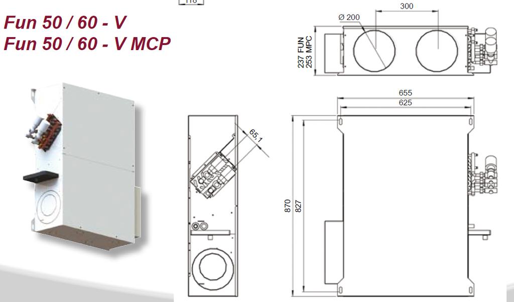
14 14
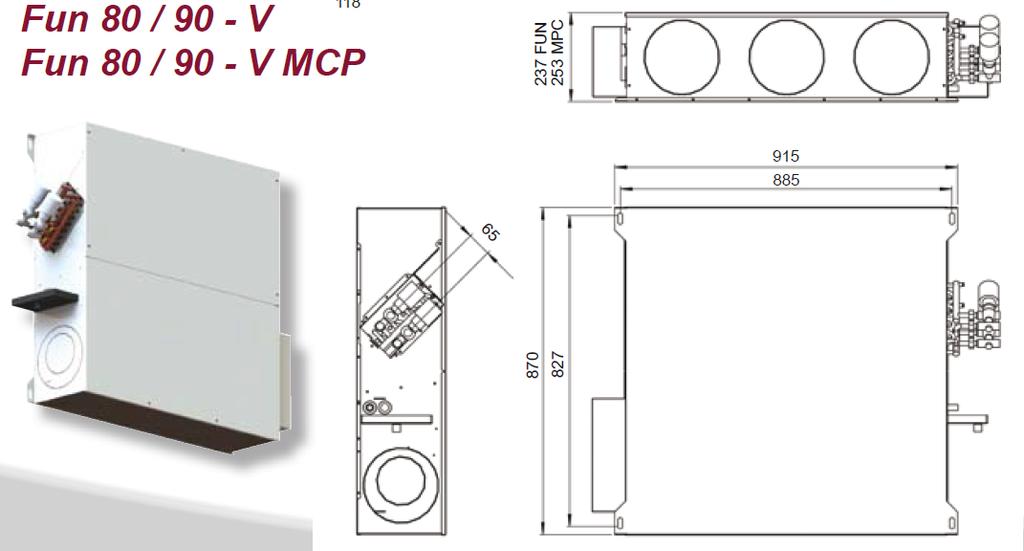
15 15
16 16


17 Drawings can be modified at any time. Formal sketch of nits delivered can be supplied on request. 17

 The condensate drain pane is an area of permanent dampness (when running with chilled water) which encourage developpement of bacteries and")

18 7. MAINTENANCE Before any maintenance operation, switch off the unit for safety reason. Maintenance can be done by qualified and authorized technicians. Filters cleaning Frequency of filters cleanings depends on the conditions of use of the unit. We recommend 2 months. Filters must be changed regularly at least every 12 months. Access to the filter is from the below. Unlock. Loosen the 4 screws and remove the below panel (suction side). Remove the filter and replace with new one. Disinfecting the condensate drain pan (FUN version I and U) The condensate drain pane is an area of permanent dampness (when running with chilled water) which encourage developpement of bacteries and legionellosis. The fan-coil FUN has been designed for hotel and medical applications with special features to let remove the drain pan easily and quickly : Removal of drain pan Access to the drain pan is from below. 1. Unscrew the 5 screws and remove the below panel (discharge side). 2. Remove the high-density foam strip supporting the drain pan (take care to support the pan by hand) 3. Slide down the drain pan by 20 mm approx. Remove the drain pan by the below (or by the side) 4. Dry the pan, eliminate moisture, use special disinfectant spray. NOTE : Removal of drain pan do not need previous removal of water coil. The water coil stay connected. 18
19 Long period stopping (> 4 months) Before to switch on the unit and at least once a year : - Clean or change the filter. If clogged filters are not changed they can increase the air pressure drop and the general performance f the unit may be degraded. - Check the coil and if necessary clean it. You may use a vacuum cleaner and/or compressed air. - Check the condensate drain pan and disinfect if necessary (moisture). - Check electrical connections. Additional maintenance To remove the water coil, just unscrew the 4 screws on each side of the unit and slide the coil (together with the drain pan). To remove the electrical fan motor : - Remove the panel below (at suction side). - Disconnect the fan assembly power supply cables (identified and note the wired fan speed). - The fan-motor is held in place by 2 M7 screws. Remove these 2 screws with an allen wrench. - Remove the fan-motor together the metal support plate. User guide Once the unit is installed and test have been achieved, explain to the user the main points of this manual (specially for maintenance) and explain the running of the unit together with the control system. How to start and stop. How to change or modify the running. How to set the temperature required. Transfer to the user this manual and all technical data sheets supplied by the manufacturer in order to be able to proceed to maintenance in the future and modify the installation in the future. The user must store these documents carefully. 8. SPARE PARTS Part FUN 40 FUN 50 FUN 60 FUN 80 FUN 90 FUN Pipes coil BAT 913 BAT 923 BAT 924 BAT 933 BAT 934 BAT Pipes coil BAT 915 BAT 925 BAT 926 BAT 935 BAT 936 BAT 946 AC Fan motor VEN 074 VEN 078 VEN x VEN x VEN x VEN 078 EC Fan motor VEN 079 VEN 079 VEN x VEN x VEN x VEN 079 EU3 Filter FTR 940 FTR 940 FTR 940 FTR 941 (I/V) FTR 941 (I/V) FTR 943 EU4 Filter FTR 944 FTR 944 FTR 944 FTR 945 (I/V) FTR 942 (U) FTR 945 (I/V) FTR942 (U) FTR 947 Drain pan support foam strip Airclip spigot DN 125 Airclip spigot DN 200 MOU020 MOU021 MOU021 M0U022 MOU022 MOU023 VIR125 VIR200 19

20 M UK Tel : Fax Rue Cassiopée Saint Médard en Jalles FRANCE 20
INSTALLATION AND MAINTENANCE MANUAL MINI AIR HANDLING UNIT «MISTRAL»
 INSTALLATION AND MAINTENANCE MANUAL MINI AIR HANDLING UNIT «MISTRAL» 1 1. Presentation 3 2. Generalities 3 2.1. Warnings Generalities 4 2.3. Safety instructions 4 3. Reception - Storage Installation 4
Installation Operation Maintenance. Ductable water unit FWD FWD-SVX01D-E4
 Installation Operation Maintenance Ductable water unit FWD 08-12 - 20-30 - 45 General Information Foreword These installation, operation and maintenance instructions are given as a guide to good practice
Installation Operation Maintenance
 Installation Operation Maintenance DUCTABLE WATER UNIT FWD 08-12 - 20-30 - 45 General Information Foreword These installation, operation and maintenance instructions are given as a guide to good practice
42GM. Individual Air Treatment Module for Variable-Flow Systems. Installation, operation and maintenance instructions
 42GM Individual Air Treatment Module for Variable-Flow Systems Installation, operation and maintenance instructions CONTENTS 1 - INTRODUCTION...3 2 - FEATURES...5 2.1 - Physical and electrical data...5
51AKS I S O OWNER S MANUAL
 LLOYD'S REGISTER QUALITY ASSURANCE 51AKS I S O 9 00 1 OWNER S MANUAL This manual applies to the following models Stand-alone Split 51AKS 085--- 51AKS 010--- 51AKS 185--- 51AKS 013--- 51AKS 113--- 51AKS
Installation, operating and maintenance ARIA
 Installation, operating and maintenance ARIA Providing indoor climate comfort ARIA-IOM-0909-E GENERAL INFORMATION Foreword This installation and maintenance manual is destined for users of the ARIA range
Installation Instructions
 38MHR Outdoor Unit Single Zone Ductless System Sizes 09 to 24 Installation Instructions NOTE: Read the entire instruction manual before starting the installation. NOTE: Images are for illustration purposes
DLCLRA. INSTALLATION INSTRUCTIONS Outdoor Unit Single Zone Ductless System Sizes 36 to 58 TABLE OF CONTENTS
 DLCLRA INSTALLATION INSTRUCTIONS Outdoor Unit Single Zone Ductless System Sizes 36 to 58 Fig. 1 - Size 36 TABLE OF CONTENTS PAGE SAFETY CONSIDERATIONS... 2 PARTS LIST... 3 SYSTEM REQUIREMENTS... 4 WIRING...
BMW E36 Thermostat Removal And Coolant Flush
 BMW E36 Thermostat Removal And Coolant Flush Disclaimer: The cooling system is critical to the proper operation of your car. Failure to properly install all of the components of the cooling system could
HG 675 CX 60 HG 675 CN 60 HG 675 CW 60
 HG 675 X 60 HG 675 CX 60 HG 675 CN 60 HG 675 CW 60 1 2 1. : 93/68: 90/396: 2006/95/CE: 2004/108/CE: - 1935/2004:. 2002/95/CE: RoHS 2.,.,,,,...,. (,..)..,,.,. ( ),,, ;,,.,.....,.,,,,,,...,. (..),,.,..,.,,,,
AUTOMATIC GRANULAR ICE FLAKER
 AUTOMATIC GRANULAR ICE FLAKER INSTRUCTIONS AND WARNINGS 24480 rev. 01 It is strictly forbidden to reproduce this instruction manual or any part thereof. Dear Customer, Congratulations on choosing a
51AKB / 51 AKC OWNER S MANUAL
 51AKB / 51 AKC OWNER S MANUAL This manual applies to the following models 51AKB 009 51AKB 012 51AKC 009 51AKC 012 Read this instruction manual thoroughly before using the air conditioner. Control panel
Mobile Air Conditioner Instruction Manual Model TC-N9KM
 Mobile Air Conditioner Instruction Manual Model TC-N9KM Please read and retain these instructions for future reference SPECIFICATION Model no. Cooling capacity Power/Ampere consumption for cooling* Air
Rif Cod i220-0
 15 52 50 6 13 53 51 2 9 8 3 20 19 18 5 1 7 14 10 4 17 Rif Cod 1 0010060 2 0060287 3 0060310 4 0080003 5 0080004 6 0080051 7 0080053 8 0080410 9 0080413 10 0080430 11 0080432 12 0080434 13 0080435 14 0080436
airooncentre.co.uk irconcentre.co.uk Xpelair Low Energy Wall/Window Fan Range GX6 EC2 GXC6 EC2 Quick Order Hotline or
 Xpelair Low Energy Wall/Window Fan Range GX6 EC2 GXC6 EC2 Installation and Maintenance Instructions Retain for future reference 3. To remove the impeller, unscrew the central screw with a 7mm nut runner
Installation, operating and servicing instructions
 English 57-115 - 144-1 - 259 Installation, operating and servicing instructions ITALIA EN 1 ITALIA English INDEX WARnINGS 3 Who should read these instructions 3 Symbols 3 Recommendations 3 Importants notes
AUTOMATIC ICE-CUBE MAKER - INSTRUCTIONS AND WARNINGS
 AUTOMATIC ICE-CUBE MAKER - INSTRUCTIONS AND WARNINGS Dear Customer, Congratulations on having chosen a quality product which will certainly fully meet your expectations. Thank you for having purchased
TABLE OF CONTENTS. NOTE: Read the entire instruction manual before starting the installation. TROUBLESHOOTING... 13
 R 410A Duct Free Split System Air Conditioner and Heat Pump Product Family: DFS4(A/H) System, DFC4(A/H)3 Outdoor, DFF4(A/H)H Indoor NOTE: Read the entire instruction manual before starting the installation.
INSTALLATION INSTRUCTIONS FOR 6532 SERIES PACKAGE HEAT PUMP
 INSTALLATION INSTRUCTIONS FOR 6532 SERIES PACKAGE HEAT PUMP RV Products A Division of Airxcel, Inc. P.O. Box 4020 Wichita, KS 67204 1976-360 (1-02) PP TABLE OF CONTENTS 1. Warnings......................................................
INSTALLATION MANUAL. Split-type Air Conditioner (Cooling and Heating) Outdoor Unit UQB09JJWC UQB12JJWC. Indoor Unit AQB09JJWC AQB12JJWC
 Outdoor Unit UQB09JJWC UQB12JJWC. Indoor Unit AQB09JJWC AQB12JJWC") AQB09JJ6WC_IM_E_2585 2006.4.17 4:26 PM Page 17 INSTALLATION MANUAL Indoor Unit AQB09JJWC AQB12JJWC Outdoor Unit UQB09JJWC UQB12JJWC ENGLISH FRANÇAIS ESPAÑOL Split-type Air Conditioner (Cooling and Heating)
AQB09JJ6WC_IM_E_2585 2006.4.17 4:26 PM Page 17 INSTALLATION MANUAL Indoor Unit AQB09JJWC AQB12JJWC Outdoor Unit UQB09JJWC UQB12JJWC ENGLISH FRANÇAIS ESPAÑOL Split-type Air Conditioner (Cooling and Heating)
G-10s. Instruction Manual. G-Series Cooler UPRIGHT COOLER. Part No.11IPA
 G-Series Cooler UPRIGHT COOLER Part No.11IPA-062800 Instruction Manual FOR YOUR FUTURE REFERENCE Thank you for using our product. This manual will guide you in getting the best use of your cooler. Remember
INSTALLATION INSTRUCTIONS FOR 6636 SERIES PACKAGE AIR CONDITIONER
 INSTALLATION INSTRUCTIONS FOR 6636 SERIES PACKAGE AIR CONDITIONER TABLE OF CONTENTS 1. Warnings...................................................... 3 2. Component Match-Up...........................................
WAILEA OWNER S MANUAL
 WAILEA OWNER S MANUAL The blades in each pack are matched for equal weight to assure smooth fan operation. If more than one fan is being installed, be careful not to mix blades from different cartons.
INSTALLATION INSTRUCTIONS FOR SERIES TWO TON HIGH EFFICIENCY PACKAGED HEAT PUMP
 RV Products Division INSTALLATION INSTRUCTIONS FOR 46515 SERIES TWO TON HIGH EFFICIENCY PACKAGED HEAT PUMP TABLE OF CONTENTS 1. Warnings.................................................. 2 2. Component
HE120, HE160 Humidifier Installation Kit
 HE120, HE160 Humidifier Installation Kit INSTALLATION INSTRUCTIONS WELCOME To the comfortable world of humidified air. When you use your Honeywell humidifier, you notice that your skin is not as dry, and
Air Conditioner. user installation & manual manual. imagine the possibilities
 ARFSSSBWK Series ARFSSSCUR AJ JNADCH Series Air Conditioner user installation & manual manual This manual is made with 100% recycled paper. imagine the possibilities Thank you for purchasing this Samsung
Inverted Bucket Steam Traps
 INSTALLATION AND MAINTENANCE INSTRUCTIONS IM-2-00-US December 201 Inverted Bucket Steam Traps Safety Information Safe operation of these products can only be guaranteed if they are properly installed,
ISCG90SS _03 ISCG90SS
 ISCG90SS 60900355_03 ISCG90SS GB IE [01] x 1 [02] x 1 [03] x 1 [04] x 8 [05] x 1 [06] x 4 [07] x 1 [08] x 1 [09] x 1 [10] x 4 [11] x 4 [12] x 1 [13] x 4 (6x70mm) [14] x 8 (6.3x17x2mm) 1 : 1 [15] x 4 (3.9x18mm)
Ceiling Concealed Fan-Coil Unit
 Installation & Maintenance Manual IM 745 Group: Fan-coil Part Number: 106333001 Date: November 2009 Ceiling Concealed Fan-Coil Unit Models: THC02, THC03, THC04, THC06, THC08, THC10, THC12 Table of Contents
Ductless Split Air Conditioner
 Ductless Split Air Conditioner Installation Manual Indoor HSU09VHG(DB)-W HSU12VHG(DB)-W HSU18VHH(DB)-W HSU24VHG(DB)-W Outdoor HSU09VHG(DB)-G HSU12VHG(DB)-G HSU18VHH(DB)-G HSU24VHG(DB)-G Table of Contents
INSTALLATION MANUAL. Split-type Air Conditioner (Cooling and Heating) Indoor Unit AQB18J6WC AQB24J2WC. Outdoor Unit UQB18J6WC UQB24J2WC
 Indoor Unit AQB18J6WC AQB24J2WC. Outdoor Unit UQB18J6WC UQB24J2WC") AQB8J6WC_IM_E_25864 2006.4.4 3:29 PM Page 7 INSTALLATION MANUAL Indoor Unit AQB8J6WC AQB24J2WC Outdoor Unit UQB8J6WC UQB24J2WC ENGLISH FRANÇAIS ESPAÑOL Split-type Air Conditioner (Cooling and Heating)
AQB8J6WC_IM_E_25864 2006.4.4 3:29 PM Page 7 INSTALLATION MANUAL Indoor Unit AQB8J6WC AQB24J2WC Outdoor Unit UQB8J6WC UQB24J2WC ENGLISH FRANÇAIS ESPAÑOL Split-type Air Conditioner (Cooling and Heating)
Titon CME1 Q Plus Mechanical Extract Ventilation Unit
 Titon CME1 Q Plus Mechanical Extract Ventilation Unit Product Manual ventilation systems 2 PCT Patent Application No PCT/GB2009/000114 Contents This is the Product Manual for the Titon CME1 Q Plus Introduction...................................
ART cm Island Curved Glass
 ART28101 90cm Island Curved Glass [01] x 1 [02] x 1 [03] x 1 [04] x 1 [05] x 4 [06] x 1 [07] x 1 [08] x 1 [09] x 4 [10] x 4 [11] x 1 [12] x 4 (6x70mm) [13] x 4 (6.3x17x2mm) [14] x 8 (4x12x1mm) [15] x 4
MODULAR AUTOMATIC GRANULAR ICE FLAKER
 MODULAR AUTOMATIC GRANULAR ICE FLAKER INSTRUCTIONS AND WARNINGS 24479 rev. 03 It is strictly forbidden to reproduce this instruction manual or any part thereof. Dear Customer, Congratulations on having
Installation Instructions T 9822 Gas Dryer. en - US, CA. To prevent accidents
 Installation Instructions T 9822 Gas Dryer To prevent accidents en - US, CA and appliance damage read these instructions before installation or use. M.-Nr. 07 431 110 2 WARNING For your safety the information
 EC Box Fan www.flaktwoods.com/oandm Safety, Installation, Operation and Maintenance Instructions CONTENTS Paragraphs Safety 1 Handling/Storage 2 Installation (Mechanical) 3 Fig. 1: Fig. 2: Tilt Mechanism
42EL Ducted Fan Coil Unit
 42EL Ducted Fan Coil Unit Supply Moduboot Installation Manual The photograph on the front cover is for illustrative purposes only and is not part of any offer for sale or contract. The manufacturer reserves
Installation Instructions
 38MPRA Outdoor Unit Single Zone Ductless System Sizes 09 to 12 Installation Instructions NOTES: Read the entire instruction manual before starting the installation. Images are for illustration purposes
LOW STATIC HYDRONIC DUCTED UNIT
 LOW STATIC HYDRONIC DUCTED UNIT PDWA-~AC SERIES PDWA(4R)-~-V-MEDC PDWA(4R)-~-V-MEEU PDWA(R)-~-V PDWA(R+1)-~-P Model cooling capacity( KW) at Medium Speed cooling capacity (KW) at Medium Speed cooling capacity
G-7s. Instruction Manual. G-Series Cooler COUNTERTOP COOLER. Part No.11IPA
 G-Series Cooler COUNTERTOP COOLER Part No.11IPA-061000 Instruction Manual FOR YOUR FUTURE REFERENCE This easy-to-use manual will guide you in getting the best use of your cooler. Remember to record the
INLINE СENTRIFUGAL FAN BOX BOX-R OPERATION MANUAL
 INLINE СENTRIFUGAL FAN BOX BOX-R OPERATION MANUAL CONTENT 3 Introduction 3 General 3 Safety rules 3 Storage and transportation rules 3 Manufacturer s warranty 4 Fan design 4 Delivery set 5 Technical data
LONGONI ENGINEERING SRL
 INDEX 1.1 Classification of heat exchanger and components 1.1.2 Type of heat exchanger and components 1.2 Purpose and scope of the manual 1.3 General instruction 1.4 Warning installation 1.5 Notes for
USER S MANUAL. VKP Series INLINE FAN
 USER S MANUAL Series INLINE FAN 2 CONTENTS Safety requirements 3 Introduction 5 Use 5 Delivery set 5 Designation key 5 Technical data 5 Design and operating logic 8 Mounting and set-up 8 Connection to
Installation Instructions
 8GXM / 0GXM Multi---Split High---Wall Duct Free Split System 8GXM --- Size 18k, k, and 0k 0GXM --- Size 9k, 1k, and 18k Installation Instructions NOTE: Read the entire instruction manual before starting
CROWN. Boiler Co. Santa-Fe Series. Hydronic Air Handlers INSTALLATION, OPERATION & MAINTENANCE INSTRUCTIONS
 CROWN Boiler Co Santa-Fe Series Hydronic Air Handlers INSTALLATION, OPERATION & MAINTENANCE INSTRUCTIONS These instructions must be affixed on or adjacent to the air handler Models: SAC049A20 SAC059A25
L A signature series TA T N E RE O, A L L A T S IN
 signature series COMMERCIAL STEAM GENERATORS INSTALLATION, OPERATION AND MAINTENANCE MANUAL INSTALLATION MANUAL COMMERCIAL STEAM GENERATOR SIGNATURE SERIES (SS) INTRODUCTION Steam Sauna manufactures steam
INSTALLATION INSTRUCTIONS
 INSTALLATION INSTRUCTIONS FCP2400D FCP3000D FCP3600D FCP4200D FCP4800D FCP6000D FCP2400C FCX2400C FCP3000C FCP3600C FCX3600C FCP4200C FCP4800C FCX4800C FCP6000C FCX6000C Require AMF001NHA Accessory No
EH0554 Indoor Climate Control
 EH0554 Indoor Climate Control 3.2kW heating or cooling capacity Air conditioning Dehumidification Cooling Efficient heating via air-source heat-pump Suitable for high- or low-wall installation No external
Installation Instructions. For the 18 Built-In Dishwasher and Front Color Panels
 Installation Instructions For the 18 Built-In Dishwasher and Front Color Panels Printed in USA 154232102 Before You Begin DO NOT INSTALL DISHWASHER UNTIL YOU HAVE READ ALL INSTRUCTIONS. FOR YOUR SAFETY,
INSTALLATION INSTRUCTIONS FOR 6536 SERIES TWO TON PACKAGED HEAT PUMP
 INSTALLATION INSTRUCTIONS FOR 6536 SERIES TWO TON PACKAGED HEAT PUMP TABLE OF CONTENTS 1. Warnings...2 2. Component Match-Up...2 3. Unit Depiction Figures...3 4. Blower Performance Data...5 5. General
Owner s Guide and Installation Manual
 Tribeca Owner s Guide and Installation Manual English Form# M6001-01 20120416 2012 Casablanca Fan Co. Welcome Your new Casablanca ceiling fan is an addition to your home or office that will provide comfort
42GR ATM Air Treatment Module
 42GR ATM Air Treatment Module Nominal air flow, size 1: 97 l/s - 350 m 3 /h size 2: 139 l/s - 500 m 3 /h Installation manual The photos shown on the front cover are solely for information, and not contractually
Breezex (BX) Heavy Duty Reversible Supply/Exhaust Fans with Reversing Switch. IMPORTANT! Read before proceeding! OPERATION & MAINTENANCE MANUAL
 Heavy Duty Reversible Supply/Exhaust Fans with Reversing Switch. IMPORTANT! Read before proceeding! OPERATION & MAINTENANCE MANUAL") Breezex (BX) Heavy Duty Reversible Supply/Exhaust Fans with Reversing Switch OPERATION & MAINTENANCE MANUAL IMPORTANT! Read before proceeding! Please read and save these instructions. Read carefully before
Breezex (BX) Heavy Duty Reversible Supply/Exhaust Fans with Reversing Switch OPERATION & MAINTENANCE MANUAL IMPORTANT! Read before proceeding! Please read and save these instructions. Read carefully before
HE360 Humidifier Installation Kit
 HE360 Humidifier Installation Kit INSTALLATION INSTRUCTIONS WELCOME To the comfortable world of humidified air. When you use your Honeywell humidifier, you notice that your skin is not as dry, and that
100cm Chimney Hood GB IE
 100cm Chimney Hood GB IE [01] x 1 [02] x 2 [03] x 2 [04] x 2 [05] x 3 [06] x 1 [07] x 1 1 : 1 [09] x 8 (3.9 x 32mm) [08] x 8 [10] x 4 (4 x 12mm) 100cm Chimney Hood GB IE Cooker Hood 04 FR Hotte Aspirante
USER MANUAL. ICON60H Version 00. Vertical Glass Hood
 USER MANUAL ICON60H Version 00 Vertical Glass Hood [02] x 1 [01] x 1 [03] x 1 [04] x 1 [07] x 1 [05] x 1 [08] x 9 [06] x 1 [09] x 9 (4 x 30mm) [10] x 2 (3 x 10mm) Cooker hood Let's get started... These
C-IV 60 CEILING FAN READ AND SAVE THESE INSTRUCTIONS. FAN RATING AC 120V. 60Hz
 C-IV 60 CEILING FAN READ AND SAVE THESE INSTRUCTIONS FAN RATING AC 120V. 60Hz Please do not use any electric or battery powered tools in the assembly and installation of this or any Matthews Fan Company
BlueHeat AirTop 2000 Heater
 BlueHeat AirTop 000 Heater Air Heater Installation Manual Ford E-Series 6.0L Diesel Beginning Model Year: 006 Special instructions for these models Part locations may differ slightly dependent on the vehicle
WHHR Midi & Midi Lite
 WHHR Midi & Midi Lite Residential Whole House Heat Recovery Units with Low Energy EC Motors Optional - Integral LCD Installation, Operating and Maintenance Instructions Image of model with LCD screen Page
DLCSRA. INSTALLATION INSTRUCTIONS Outdoor Unit Ductless Split System Sizes 09 to 36 TABLE OF CONTENTS
 DLCSRA INSTALLATION INSTRUCTIONS Outdoor Unit Ductless Split System Sizes 09 to 36 NOTES: Read the entire instruction manual before starting the installation. Images are for illustration purposes only.
40LM Hz INSTALLATION, START-UP AND SERVICE INSTRUCTIONS CHILLED WATER FAN COIL UNIT
 Carrier International Sdn. Bhd. Malaysia INSTALLATION, START-UP AND SERVICE INSTRUCTIONS CHILLED WATER FAN COIL UNIT 40LM 120-200 50Hz CONTENTS: Physical Data & Dimension 1-3 Safety Considerations 4 Rigging
Refrigerator BRFB1920SS BRFB1900FBI BRFB1920FBI
 Refrigerator BRFB1920SS BRFB1900FBI BRFB1920FBI Table of Contents Symbols and Their Meanings... 3 Product weight... 5 Load bearing capacity of the doors... 5 Climate class... 5 Product Information:...
DC Heat Recovery Unit MVHR Wholehouse heat recovery unit
 DC Heat Recovery Unit MVHR Wholehouse heat recovery unit Stock Ref. N DC Heat Recovery Unit MVHR 443423 Installation, Maintenance & Users Instructions PLEASE READ INSTRUCTIONS IN CONJUNCTION WITH ILLUSTRATIONS.
Series 1140 and 1141 Temperature Regulators
 Hoffman Specialty Installation & Maintenance Instructions HS-504(E) Series 1140 and 1141 Temperature Regulators! CAUTION FOLLOW ALL INSTALLATION AND OPERATING INSTRUCTIONS. TURN OFF WATER OR STEAM BEFORE
RV Products Division INSTALLATION INSTRUCTIONS FOR SERIES PACKAGE AIR CONDITIONER
 RV Products Division INSTALLATION INSTRUCTIONS FOR 46413 SERIES PACKAGE AIR CONDITIONER 1. WARNINGS IMPORTANT NOTICE These instructions are for the use of qualified individuals specially trained and experienced
SPX SERIES PACKAGED AIR CONDITIONING/HEAT PUMP UNITS INSTALLATION, OPERATION AND MAINTENANCE INSTRUCTIONS
 SPX SERIES PACKAGED AIR CONDITIONING/HEAT PUMP UNITS INSTALLATION, OPERATION AND MAINTENANCE INSTRUCTIONS **WARNING TO INSTALLER, SERVICE PERSONNEL AND OWNER** Altering the product or replacing parts with
INSTRUCTION MANUAL MODEL: 690E
 1 INSTRUCTION MANUAL ALEKO Drywall Sander MODEL: 690E READ THROUGH CAREFULLY AND UNDERSTAND THESE INSTRUCTIONS BEFORE USE Visit our web site for more great products, parts and accessories: 2 3 4 5 6 Caution!
Centrif Duo & Centrif Duo Plus
 Centrif Duo & Centrif Duo Plus Installation and Wiring Instructions Stock Ref. N Centrif Duo P 25 61 20D Centrif Duo T 25 62 20D Centrif Duo DP 25 63 20D Centrif Duo HTP 25 64 20D Centrif Duo Centrif Duo
Owner s Guide and Installation Manual
 For Your Records and Warranty Assistance For reference, also attach your receipt or a copy of your receipt to the manual. Model Name Type 2A Models Owner s Guide and Installation Manual Model No. Date
DMX fog machine User manual
 DMX fog machine User manual 1 Safety precautions WARNING: This unit may cause serious injury when used incorrect. It therefore is strongly advised to read this user manual carefully, to get familiar with
EVAPORATIVE COOLER PUMPS
 EVAPORATIVE COOLER PUMPS ebmpapst Evaporative Cooler Pump EBMALPHA $144.65 @ 1. metre Head @ 2. metre Head Power Supply 32 litres/min 25 litres/min 24V/1/5Hz Nominal Watts 5 watts Outlet Connection 2mm
EH0533 Indoor Climate Control
 EH0533 Indoor Climate Control 2.8 kw of cooling, 2.9 kw of heating Air Conditioning Efficient heating (air-source heat-pump) Cooling Remote control Suitable for low-wall installation No external unit required
Titon HRV1 Q Plus HRV1.5 Q Plus HRV2 Q Plus Heat Recovery Ventilation Units
 Titon HRV1 Q Plus HRV1.5 Q Plus HRV2 Q Plus Heat Recovery Ventilation Units Product Manual ventilation systems 2 PCT Patent Application No PCT/GB2009/000114 Contents Introduction...................................
Installation and operating instructions. DK energy storage and DK energy buffer
 Installation and operating instructions DK energy storage and DK energy buffer Edition: 08-2015 1 Preliminary note With this DK energy storage / DK energy buffer you purchased a DK quality product. The
"WHHR125DC" Whole House Heat Recovery Unit with Low Energy DC Motor. Installation, Operating and Maintenance Instructions domestic and commercial use
 "WHHR125DC" Whole House Heat Recovery Unit with Low Energy DC Motor Installation, Operating and Maintenance Instructions domestic and commercial use Page 2 Contents Section Page Number Introduction 3 How
ISOLATED DIRECT DRIVE PLENUM FAN (IDDP)
") Our Expertise, Your Air-Moving Solution ISOLATED DIRECT DRIVE PLENUM FAN (IDDP) PART# 0601710001_rev_A INSTALLATION, OPERATION & MAINTENANCE MANUAL Please read and save these instructions for future reference.
Our Expertise, Your Air-Moving Solution ISOLATED DIRECT DRIVE PLENUM FAN (IDDP) PART# 0601710001_rev_A INSTALLATION, OPERATION & MAINTENANCE MANUAL Please read and save these instructions for future reference.
Instruction Manual - Anti-Siphon Ejector Chlorine & Sulfur Dioxide 500 PPD (10 kg/h) Maximum Capacity
 Maximum Capacity") - Anti-Siphon Ejector Chlorine & Sulfur Dioxide 500 PPD (10 kg/h) Maximum Capacity 100 PPD (2 kg/h) Chlorine or Sulfur Dioxide 250 & 500 PPD (5 & 10 kg/h) Chlorine or Sulfur Dioxide Anti-Siphon Ejector
- Anti-Siphon Ejector Chlorine & Sulfur Dioxide 500 PPD (10 kg/h) Maximum Capacity 100 PPD (2 kg/h) Chlorine or Sulfur Dioxide 250 & 500 PPD (5 & 10 kg/h) Chlorine or Sulfur Dioxide Anti-Siphon Ejector
OK, OKA, OKAF; ELD; ELDM; ELH; OKC; SC; SCA; SCAF; OK-LN; OKA-LN; OKAF-LN.
 INSTALLATION, OPERATION & SERVICE MANUAL FOR COOLER TYPES OK, OKA, OKAF; ELD; ELDM; ELH; OKC; SC; SCA; SCAF; OK-LN; OKA-LN; OKAF-LN. 1. Introduction This manual is a guide for the installation, maintenance
ST. KITTS CEILING FAN
 ITEM #0845047 ST. KITTS CEILING FAN MODEL #40829 Questions, problems or missing parts? Before returning this item to your retailer, call our customer service department at 1-800-643-0067, Monday - Thursday,
MODEL 598A TWO-SPEED PLUS CENTRAL AIR CONDITIONER
 USER S INFORMATION MANUAL MODEL 598A TWO-SPEED PLUS CENTRAL AIR CONDITIONER NOTE TO INSTALLER: This manual must be left with the equipment user. WELCOME TO EFFICIENT HOME COOLING COMFORT Congratulations
General System Layout Sketch
 General System Layout Sketch EZ-37 Solar Panels PV panel Glycol Fill Valve Expansion Tank ` 1 Introduction This document describes how to install a Heliatos GH type solar water heating system. These systems
FIGURE 1. Model RD107
 General Description The Model RD107 Commercial Flat Concealed Sprinklers are automatic sprinklers of the compressed fusible solder type. These are decorative and standard response. The frame of the sprinkler
21 20 LITER GAS FRYER FFA3200 INSTALLATION AND SERVICING.
 21 20 LITER GAS FRYER FFA3200 INSTALLATION AND SERVICING www.anvilworld.com 20 ALL ANVIL EQUIPMENT COMES WITH A ONE YEAR WARRANTY ON COMPONENTS AND DEFECTIVE WORKMANSHIP. www.anvilworld.com 19 20 LITER
Internal/External Wall/Window Fan Range GX6. Installation and maintenance instructions Retain for future use
 Internal/External Wall/Window Fan Range GX6 Installation and maintenance instructions Retain for future use A GLASS WINDOW B C D ( 6 see F ) 13 E1 E2 E3 G1 G2 G3 G4 H I GB Xpelair GX6, GXC6, GXC6T, GX6HT
Installation and maintenance instructions for cabin units type vertical IDAC (V50)
") GB Installation and maintenance instructions for cabin units type vertical IDAC (V50). Application. Bundled parts. Handling. Marking. Weight. Transport. Storage 5. Installation 5. Mounting 5. Water trap
GB Installation and maintenance instructions for cabin units type vertical IDAC (V50). Application. Bundled parts. Handling. Marking. Weight. Transport. Storage 5. Installation 5. Mounting 5. Water trap
AHU INSTALLATION & OPERATION MANUAL
 AHU INSTALLATION & OPERATION MANUAL VERSION 2 AIR HANDLING UNIT MODELS: AHU 500, AHU 900, AHU 1200, AHU 1700, AHU 2000, AHU 2500, AHU3500, AHU 4500, AHU 5000, AHU 6000, AHU 7000, AHU 8000, AHU 10000, AHU
User Manual GV25 GV35 GV702. Company information: Original instructions GV12066 (1)
") User Manual Original instructions GV25 GV35 GV702 Company information: www.vipercleaning.eu info-eu@vipercleaning.com GV12066 (1) 2012-04-10 USER MANUAL ENGLISH TABLE OF CONTENTS Introduction... 4 Manual
User Manual Original instructions GV25 GV35 GV702 Company information: www.vipercleaning.eu info-eu@vipercleaning.com GV12066 (1) 2012-04-10 USER MANUAL ENGLISH TABLE OF CONTENTS Introduction... 4 Manual
Internet Version for Reference Only INDUCED DRAFT COMMERCIAL WATER HEATERS SUPPLEMENT INSTRUCTIONS TO PART #
 INDUCED DRAFT COMMERCIAL WATER HEATERS SUPPLEMENT INSTRUCTIONS TO PART #238-39387-00 THIS INSTRUCTION SUPPLEMENT IS ONLY INTENDED TO GIVE INSTALLATION INSTRUCTIONS AND INFORMATION RELATED TO THE INDUCED
COMBY 4000 & 9000 STEAM CLEANER OPERATOR MANUAL
 COMBY 4000 & 9000 STEAM CLEANER OPERATOR MANUAL Clemas & Co. Unit 5 Ashchurch Business Centre, Alexandra Way, Tewkesbury, Gloucestershire, GL20 8NB. Tel: 01684 850777 Fax: 01684 850707 Email: info@clemas.co.uk
Installation Instructions
 40MBD Ducted Style Ductless System Sizes 09 to 48 Installation Instructions NOTE: Read the entire instruction manual before starting the installation. TABLE OF CONTENTS PAGE SAFETY CONSIDERATIONS... 2
SERVICE MANUAL. Bradford White ElectriFLEX HD (Heavy Duty) Commercial Electric Water Heater CEHD SERIES Immersion Thermostat Models
 Commercial Electric Water Heater CEHD SERIES Immersion Thermostat Models") Bradford White ElectriFLEX HD (Heavy Duty) Commercial Electric Water Heater CEHD SERIES Immersion Thermostat Models SERVICE MANUAL Troubleshooting Guide and Instructions for Service (To be performed ONLY
Bradford White ElectriFLEX HD (Heavy Duty) Commercial Electric Water Heater CEHD SERIES Immersion Thermostat Models SERVICE MANUAL Troubleshooting Guide and Instructions for Service (To be performed ONLY
CG60/ 70/ 80/ 90/ 100 SS/BK
 CG60/ 70/ 80/ 90/ 100 SS/BK GB IE [01] x 1 [02] x 1 [03] x 1 [04] x 2 [05] x 1 [06] x 1 [07] x 1 [08] x 4 [09] x 4 [10] x 1 [11] x 6 1 : 1 [12] x 4 [13] x 6 (3.9 x 32mm) [14] x 4 (3.4 x 10mm) CG60/ 70/
Hood Depot Internatioonal, Inc., Phone S. Powerline Road, Deerfield Beach, FL
 The Kitchen Cool by Hood Depot is a conditioned make up air unit design with flexibility, form and function kept in mind. Our unit offers a variety of configurations that allow the customer to customize
THROUGH-WALL AIR-TO-AIR HEAT PUMP AND AIR CONDITIONER. Instruction Manual. Model AMB-12H
 THROUGH-WALL AIR-TO-AIR HEAT PUMP AND AIR CONDITIONER Instruction Manual Model AMB-12H PLEASE READ THIS INSTRUCTION MANUAL CAREFULLY BEFORE USING THIS UNIT. Table of Contents 1. SAFETY WARNINGS 2 2. CONSTRUCTION...
Operating Instructions
 Operating Instructions TEKA Cartmaster Type PF-W 1, PF-W 2 TEKA Absaug- und Entsorgungstechnologie GmbH Industriestraße 13 D-46342 Velen Postfach 1137 D-46334 Velen Tel.: +49 (0) 2863 9282-0 Fax: +49 (0)
Installation Instructions
 Installation Instructions Downdraft Vent Systems PVB94 PVB98 ZVB30 ZVB36 31-10728-8 11-14 GE 1 Safety Information If you have questions, call 800.GE.CARES or visit our website at: GEAppliances.com BEFORE
KR Series Air Defrost Unit Coolers Operating and Installation Manual
 KR Series Air Defrost Unit Coolers Operating and Installation Manual KR Air Defrost Unit Coolers (PN E108317_L) TABLE OF CONTENTS 1 RECEIPT OF EQUIPMENT... 2 1.1 INSPECTION... 2 1.2 LOSS OF GAS HOLDING
WC2 & WC3 Installation & Maintenance Instructions
 WC2 & WC3 Installation & Maintenance Instructions Please leave this instruction booklet with the home owner as it contains important guarantee, maintenance and safety information WC3 shown WC2 WC3 IMPORTANT
WINDOW TYPE ROOM AIR CONDITIONER OPERATION AND INSTALLATION MANUAL
 MODEL RA-0LDF RA-3LDF WINDOW TYPE ROOM AIR CONDITIONER OPERATION AND INSTALLATION MANUAL AIR DEFLECTORS VERTICAL DEFLECTORS Vertical de ectors at both sides of outlets can be set to either auto-swing or
Operation Manual Portable Room Air Conditioner Models: RPC26WA / RPC35WA / RPC41WA
 HIGH MID LOW DRY FAN COLL HEAT TIMER SLEEP SWING Operation Manual Portable Room Air Conditioner Models: RPC26WA / RPC35WA / RPC41WA F C This appliance shall be installed in accordance with: Manufacturer