SCD Series "All-in-One" Compact Dryer
|
|
|
- Agatha Lawson
- 6 years ago
- Views:
Transcription
1 SCD Series "All-in-One" Compact Dryer Date: Jul Version: Ver.D (English)
2
3 Contents 1. General Description Coding Principle The main features Technical Specifications Specifications Technical Specifications Drying Capacity Safety Regulations Safety Regulations for the Blowers Notes of using material storage bin of optional grade (MST-80U-OP) Notes of using HEPA Important notices for using SHR-CP-3U Safety Signs and Labels Signs and Labels Transportation and Storage of the Machine Exemption Clause Maintenance Schedule Structure Characteristics and Working Principle Working Principle Relative Humidity and Dew-point Why Choose "All-in-One" Compact Dryer Working Principle Dew-point Comparison Drawing and Parts List Structural Drawing Assembly Drawing (Fully-integral design) (SCD-20U/30H~40U/50H) Parts List (Fully-integral design)(scd-20u/30h~40u/50h) Assembly Drawing (Fully-integral design) (SCD-80U/50H~230U/120H) (92)
4 2.6.5 Parts List (Fully-integral design)(scd-80u/50h~230u/120h) Assembly Drawing (Fully-integral design) (SCD-300U/200H~450U/200H) Parts List (Fully-integral design)(scd-300u/200h~450u/200h) Assembly Drawing (Semi-integral design) Parts List (Semi-integral Design) Filter & Pressure Regulating Valve Drawing Heater Honeycomb Parts List of Honeycomb (SCD-900U/700H 1200U/700H) Material Stage Bin of Optical Grade MST-80U-OP High-efficiency Filter HEPA Important notices for using SHR-CP-3U Main Electrical Components Description Operation Procedures Operation Regulations Description of touch screen Touch panel appear error Screen operation flow Table Menu particular Installation Testing Attention Honeycomb-rotor What is Honeycomb-rotor Installation of the Rotor Heater Assemblies Installation of Blowers Drying Blower Regeneration Blower Conveying Blower Installation of Drying Hopper Filter & Pressure Regulating Valve EGO (92)
5 3.4.7 Cyclone Dust Collector Oil Filter Plate Heat Exchanger Application and Operation Panel Operation Temperature Setup PID Auto-tuning Setting Intermittent Running Setup Weekly Time Start Setup Present Time Modification Weekly Time Start Lock Setup Way The second level of Advanced Setting Wrong Codes Remark Operation of Conveying System Operation of Dehumidifying System Installation for Dewpoint Monitor Trouble-shooting Maintenance and Repair Filter & Pressure Regulating Valve Filter & Pressure Regulating Valve Drawing Filter & Pressure Regulating Valve Operation steps Air Filters Blower Motors The Useful Life of the Key Parts of the Product Honeycomb Cooler Clean of Y Type Strainer Maintenance Schedule General Machine Information Installation & Inspection Daily Checking Weekly Checking (92)
6 6.7.5 Monthly Checking Half-yearly Checking Yearly Checking year Checking Table Index Table 1-1:Specifications (Fully-integral Design)...12 Table 1-2:Specifications (Semi-integral Design)...13 Table 1-3:Drying Capacity Table 1-4:Drying Capacity Table 2-1:Parts List (Fully-integral design)(scd-20u/30h~40u/50h)...29 Table 2-2:Parts List (Fully-integral design)(scd-80u/50h~230u/120h)...32 Table 2-3:Parts List (Fully-integral design) (SCD-300U/200H~450U/200H)..35 Table 2-4:Parts List (Semi-integral Design)(SCD-600U/400H~750U/400H)..38 Table 2-5:Parts List (Semi-integral Design) (SCD-900U/700H~1200U/700H)40 Table 2-6:Parts List...45 Table 2-7:Touch panel information...51 Table 2-8:Adjustment of Proportion (P)...57 Table 2-9:Adjustment of Integral Time (I)...57 Table 2-10:Adjustment of Differential Time (D)...57 Table 2-11:System Alarm Information List...61 Table 4-1:Wrong Codes Remark...78 Table 6-1:The Useful Life of the Key Parts of The Product...89 Picture Index Picture 1-1:Technical Specifications...14 Picture 1-2:Safety Regulations for the Blowers...17 Picture 1-3:Material Stage Bin of Optical Grade MST-80U-OP...18 Picture 1-4:High-efficiency filter...19 Picture 1-5:Important notices for using...19 Picture 1-6:Safety Signs and Labels...20 Picture 1-7:Maintenance Schedule (92)
7 Picture 2-1:SCD Working Principle...25 Picture 2-2:SCD-OP Working Principle (With plate heat exchanger) (Option)25 Picture 2-3:Dew-point Comparison...26 Picture 2-4:Structural Drawing...27 Picture 2-5:Assembly Drawing (Fully-integral design)(scd-20u/30h~40u/50h)...28 Picture 2-6:Assembly Drawing (Fully-integral design) (SCD-80U/50H~230U/120H)...31 Picture 2-7:Assembly Drawing (Fully-integral design) (SCD-300U/200H~450U/200H)...34 Picture 2-8:Assembly Drawing (Semi-integral design)...37 Picture 2-9:Filter & Pressure Regulating Valve Drawing...42 Picture 2-10:Heater...43 Picture 2-11:Honeycomb Parts Drawing (SCD-900U/700H 1200U/700H)...44 Picture 2-12:Material Stage Bin of Optical Grade MST-80U-OP...46 Picture 2-13:High-efficiency Filter HEPA...47 Picture 2-14:Important notices for using SHR-CP-3U...48 Picture 2-15:Overload Relay...49 Picture 2-16:Operation Regulations...50 Picture 2-17:Description of touch screen...51 Picture 2-18:Screen operation flow Table...52 Picture 2-19:System Default System...52 Picture 2-20:Drying Process Screen...53 Picture 2-21:Conveying Monitoring Screen...54 Picture 2-22:Temperature Parameters Setting Picture 2-23:Temperature Parameters Setting Picture 2-24:Drying & Regeneration Temperature Control Parameters...56 Picture 2-25:Conveying Parameter Setting...58 Picture 2-26:Time Setting Picture 2-27:Time Setting Picture 2-28:Alarm Fault Records...60 Picture 2-29:Help Screen...62 Picture 3-1:Installation drawing...63 Picture 3-2:Schematic drawing of installation (Fully-integral design) (92)
8 Picture 3-3:Schematic drawing of installation (semi-integral design)...64 Picture 3-4:Honeycomb rotor...65 Picture 3-5:Installation of the Rotor...66 Picture 3-6:Heater Assemblies...67 Picture 3-7:Installation of Blowers...68 Picture 3-8:Conveying Blower...68 Picture 3-9:EGO...69 Picture 3-10:Installation Diagram of Cyclone Dust Collector...69 Picture 3-11:Installation Diagram of Oil Filter...70 Picture 3-12:Plate Heat Exchanger over Figure...71 Picture 4-1:Intermittent Running Setup Picture 4-2:Intermittent Running Setup Picture 4-3:Intermittent Running Setup Picture 4-4:Weekly Time Start Setup Picture 4-5:Weekly Time Start Setup Picture 4-6:Weekly Time Start Setup Picture 4-7:Weekly Time Start Setup Picture 4-8:Weekly Time Start Setup Picture 4-9:Temperature Controller...79 Picture 4-10:Password Lock Picture 4-11:Password Lock Picture 4-12:Hole Site...80 Picture 4-13:Parts of Dew-point Monitor...81 Picture 4-14:Copper Joint Assembly of Original Machine...81 Picture 4-15:Installation Seat...81 Picture 4-16:Installation for Transmitter...82 Picture 4-17:Connection of Signal Wire...82 Picture 4-18:Installation for Dew-point Monitor...82 Picture 4-19:Connection of Dew-point Monitor...83 Picture 6-1:Filter & Pressure Regulating Valve Drawing...87 Picture 6-2:Air Filters...88 Picture 6-3:Blower Motors (92)


9 1. General Description Read this manual carefully before operation to prevent damage of the machine or personal injuries. SCD series dehumidifying dryer possesses three functions of dehumidification, drying and two-stage conveying. It is very suitable for drying engineering plastics materials with hygroscopicity such as PA, PC, PBT, PET. Among them, optics SCD-OP could be used in processing application of lens, LCD backlight board and discs, it has dew-point of below -40 under ideal condition. SCD-160U/120H SCD-450U/300H-LC-D 9(92)
10 1.1 Coding Principle SCD xxxu / xxxh xxx Option* Dehumidfying Air Quantity(m³/hr) H: Honeycomb Rotor Hopper Capacity(L) U: European Type Shini Compact Dryer Notes: * LC=PLC+HMI D=Dew-point Monitor P=Polished Hopper Inside OP=Optical Class M2=Three-stage Conveying ES=Energy-saving CE=CE Conformity HE=Drying Plate Heat Exchanger 1.2 The main features 1) Standard configuration Combine the function of dehumidifying, drying and two-stage conveying into a single unit. SCD Dryer Loaders are equipped with honeycomb rotor to obtain stable low dew-point drying air. It have two models: semi-open and hermetic. Feeding system is equipped with shut-off valve to ensure no surplus raw material in hopper tubes. Microprocessor is available as standard equipment. Optical SCD-OP series together with powder-removing hopper which can help avoid stain in the production of optical products. Optical-class SCD-OP material contact surfaces are all mirror polished and collocates conveying system with closed loop to avoid contamination and moisture regain. Optical-class SCD-OP system has standard configuration high efficiency particulate absorbing filter, which can filter tiny ion of 0.3μm with filter ratio of %. Heat preserved drying hopper barrel adopts down blowpipe design and collocates with cyclone air exhaust to avoid heat lost and improve drying efficiency. This dehumidifying series adopts double cooler structure to ensure lower 10(92)
11 return air temperature and dew-point. 2) Accessory option PLC control and touch HMI LCD are optional, which makes operation convenient for machine s automatic running. Highly efficient filter and optical storage hopper are optional to ensure no air contamination to raw material. SCD-ES series is equipped with regenerative plate heat exchanger, which can save 3~6% of total power consumption. SCD series is equipped with drying plate heat exchanger, which can save 0~19% of total power consumption. For SCD-ES series, dew-point value is adjustable. The dew-point temperature can be set between -40 to +10 according to actual need of plastics material. 0~10% of total power consumption can be saved. SCD-ES is equipped with the function of controllable drying capacity. Once the name of dried plastics material and material consumption in each hour are set, the system will automatically adjust air volume and consumption. Material consumption in each hour is 40~100% of drying capacity, which saves 35~0% of the total power consumption. In this way, it achieves maximum of resources collocation and avoids over-drying which affects physical and mechanical capacity of plastics material. All service work should be carried out by a person with technical training or corresponding professional experience. The manual contains instructions for both handling and servicing. Chapter 6, which contains service instructions intended for service engineers. Other chapters contain instructions for the daily operator. Any modifications of the machine must be approved by SHINI in order to avoid personal injury and damage to machine. We shall not be liable for any damage caused by unauthorized change of the machine. Our company provides excellent after-sales service. Should you have any problem during using the machine, please contact the company or the local vendor. Headquarter and Taipei factory: Tel: (886) Shini Plastics Technologies (Dongguan), Inc: Tel: (86) Shini Plastics Technologies India Pvt.Ltd.: Tel: (91) (92)
12 1.3 Technical Specifications Specifications Table 1-1:Specifications (Fully-integral Design) Model SCD- 20U/30H (-OP) 40U/30H (-OP) 40U/50H 80U/50H (-OP) 120U/80H (-OP) 160U/80H 160U/120H 230U/120H 300U/200H 450U/200H Drying System Dying Heater Power (kw) Dying Blower Power (kw, 50/60Hz) Hopper Capacity (L) Dehumidifying System Regenerating Heater Power (kw) Regenerating Blower Power (kw, 50/60Hz) Dehumidifying Air quantity (m 3 /hr, 50/60Hz) Feeding System Feeding Blower Power (kw, 50/60Hz) Dia. of Material Pipe (inch) SHR-U-E Hopper (L) SHR-U Hopper (L) Dimensions (3*) 3(3*) 3 6(3*) 6(3*) H(mm) 1490(1400) 1550(1500) (1670) 1990(1710) W(mm) 1000(1050) 1040(1050) (1240) 1105(1240) D(mm) 875(900) 875(900) (1000) 875(1000) Weight (kg) 280(235) 295(280) (330) 340(385) (92)
13 Table 1-2:Specifications (Semi-integral Design) Model SCD- 600U/400H 750U/400H 900U/700H 1200U/700H Drying System Drying Heater Power (kw) Drying Blower Power (kw, 50/60Hz) 3.75 / / / / 6.3 Hopper Capacity (L) Dehumidifying System Regenerating Heater Power (kw) Regenerating Blower Power (kw, 50/60Hz) Dehumidifying Air quantity (m 3 /hr, 50/60Hz) 0.75 / / / / / / / / 780 Feeding System Feeding Blower Power (kw) Dia. of Material Pipe (inch) SHR-U-E Hopper Receiver (L) SHR-U Hopper Receiver (L) Dimensions H(mm) W(mm) D(mm) Weight (kg) Note: 1) For models that are equipped with dew-point monitor, add "D" at model behind. 2) For models with the polished hopper inside, add "P" at model behind. 3) For models of providing material for two IMMs with three-stage conveying function and adopt PLC control plus LCD touch screen, add "LC" at model behind. 4) Power: 3Φ, 230/400/460/575VAC, 50/60Hz. 5) * stands for hopper receiver SHR-CP-U. We reserve the right to change specifications without prior notice. 13(92)


14 1.3.2 Technical Specifications SCD Hermetic SCD Semi-open SCD-OP Picture 1-1:Technical Specifications 14(92)
15 1.3.3 Drying Capacity Table 1-3:Drying Capacity 1 Material Drying Temp. ( ) Drying Time (hr) 20U /30H 40U /30H 40U /50H Drying Capacity (kg/hr) ABS U /50H 120U /80H 160U /80H 160U /120H 230U /120H 300U /200H CA CAB CP LCP POM PMMA IONOMER PA6/6.6/ PA PA PC PU PBT PE PEI PET PETG PEN PES PMMA PPO PPS PI PP PS(GP) PSU PVC SAN(AS) TPE Note: 1. Please refer to above drying capacity of SCD machine, select the right model according to material usage of processing machine. 2. Please consult Shini service staff for model selection. 450U /200H 15(92)
16 Table 1-4:Drying Capacity 2 Material Drying Temp. ( ) Drying Time (hr) 600U /400H Drying Capacity (kg/hr) 750U /400H 900U /700H ABS CA CAB CP LCP POM PMMA IONOMER PA6/6.6/ PA PA PC PU PBT PE PEI PET PETG PEN PES PMMA PPO PPS PI PP PS(GP) PSU PVC SAN(AS) TPE U /700H Note: 1. Please refer to above drying capacity of SCD machine, select the right model according to material usage of processing machine. 2. Please consult Shini service staff for model selection. 16(92)
 Under normal operation, the blower motor's current loading will increase or reduce according to air pressure's change accordingly.")
17 1.4 Safety Regulations Safety Regulations for the Blowers 1) Under normal operation, the blowers will generate high temperature. Do not touch blower's case to avoid any physical injury. 2) Under normal operation, the blower motor's current loading will increase or reduce according to air pressure's change accordingly. While installation, an adequate motor overload protection switch should be installed with full loading test, to ensure operating safely under full-loading to avoid motor's damage. 3) To avoid any block materials, dust, powder, fiber particles and water drops entering the blower, and hence cause the deficiency of its performance. This machine is well designed with air filters, so please clean up the filter with any foreign particles (recommended to clean up this filter weekly). 4) Clean the blowers both internal and external parts (especially for the fan cooling path), and remove surface dust if necessary. If more dusts are accumulated, it will cause deficiency for ventilation, temperature rising, vacuum power reduced, vibration increased and so it will cause machine broke down. 5) Ball bearing, oil seal and soundproof are belonging to consumable parts and so it has a life period and equires regular replacement. Meanwhile, blade, external case, and metallic screen etc. should be replaced regularly for best performance. 6) Under normal operation, if the blowers are not running smoothly or abnormal noise appeared. Please immediately shut down the machine for repair. Picture 1-2:Safety Regulations for the Blowers Notes of using material storage bin of optional grade (MST-80U-OP) 1) Check whether internal bin and connecting pipe are clean or not before using. 17(92)
 Take note of air flow direction of plate filter, avoiding reversing side.")
18 2) Using equipped with HEPA and model of optional grade series. 3) If customer do not equip with HEPA, filter with accuracy of 5um is available, which is installed inside storage bin. Picture 1-3:Material Stage Bin of Optical Grade MST-80U-OP Notes of using HEPA 1) Take note of air flow direction of plate filter, avoiding reversing side. 2) Take note of sequence of installation of the two plate filter, that is installed above with accuracy of 5um and below with accuracy of 0.3um. 3) The two plate filters are installed tightly to align locating device and keep the detection location of upper and lower pressure on the same side. 4) The upper low efficient filter should be cleaned timely (once a week is suggested). When air supply is lacked obviously and cleaning efficiency of cylinder type filter is not obvious, we suggest cleaning middle-efficiency filter with accuracy of 5um, or replace high-efficiency filter with accuracy of 0.3um. 5) It is not available for high-efficiency filter with accuracy of 0.3um to recycle for use because of vulnerability. 6) Differential pressure indicator optionally connects to the pressure detection location of upper and lower plate cover. When pressure difference is above 1000Pa, we suggest cleaning middle-efficiency filter with accuracy of 5um. And if the efficiency is not good, we suggest replacing high-efficiency filter with accuracy of 0.3um. 18(92)
 The screener needs regular cleaning, once a week is recommended. 3) The glass tube and the packing are consumables. Be careful when using and back up is necessary.")
19 Picture 1-4:High-efficiency filter Important notices for using SHR-CP-3U 1) Check whether the feed-in pipes are clean before using. 2) The screener needs regular cleaning, once a week is recommended. 3) The glass tube and the packing are consumables. Be careful when using and back up is necessary. 4) Location of the level sensor can be adjusted according to user s requirement. Picture 1-5:Important notices for using 19(92)

20 1.4.5 Safety Signs and Labels Danger! High voltage danger! This label is stuck on the electrical boxes. Attention! This label means that this area should be taken care! Warning! High temperature, take care of hands! This label should be stick to the shell of heater. Attention! No need for regular inspection because all the electrical parts in the control unit are fixed tightly! Note! The EGO over-temperature protection is only for process heater protection, not for material protection usage, the default setting should not be changed. Note! To prevent over-temperature alarm from causing machine shutdown, don t randomly adjust EGO setting temp. Picture 1-6:Safety Signs and Labels 20(92)
21 1.4.6 Signs and Labels Water inlet: inlet for replenishing water and cooling water. Water outlet: drainage outlet Transportation and Storage of the Machine Transportation 1) SCD series "All-in-one" compact dryer are packed in crates or plywood cases with wooden pallet at the bottom, suitable for quick positioning by fork lift. 2) After unpacked, castors equipped on the machine can be used for ease of movement. 3) Do not rotate the machine and avoid collision with other objects during transportation to prevent improper functioning. 4) The structure of the machine is well-balanced, although it should also be handled with care when lifting the machine for fear of falling down. 5) The machine and its attached parts can be kept at a temperature from -25 to +55 for long distance transportation and for a short distance, it can be transported with temperature under +70. Storage 1) SCD series "All-in-One" compact dryer should be stored indoors with temperature kept from 5 to 40 and humidity below 80%. 2) Disconnect all power supply and turn off main switch and control switch. 3) Keep the whole machine, especially the electrical components away from water to avoid potential troubles caused by the water. 4) Plastic film should be used to protect the machine from dust and rains. Working environment Indoors in a dry environment with max. temperature +45 and humidity no more than 80%. Do not use the machine 1) If it is with a damaged cord. 2) On a wet floor or when it is exposed to rain to avoid electrical shock. 3) If it has been dropped or damaged until it is checked or fixed by a qualified serviceman. 4) This equipment works normally in the environment with altitude within 3000m. 5) At least a clearance of 1m surrounding the equipment is required during operation. Keep this equipment away from flammable sources at least two 21(92)
22 meters. 6) Avoid vibration, magnetic disturbance at the operation area. Rejected parts disposal When the equipment has run out its life time and can not be used any more, unplug the power supply and dispose of it properly according to local code. Fire hazard. In case of fire, CO 2 dry powder fire extinguisher should be applied. 1.5 Exemption Clause The following statements clarify the responsibilities and regulations born by any buyer or user who purchases products and accessories from Shini (including employees and agents). Shini is exempted from liability for any costs, fees, claims and losses caused by reasons below: 1. Any careless or man-made installations, operation and maintenances upon machines without referring to the Manual prior to machine using. 2. Any incidents beyond human reasonable controls, which include man-made vicious or deliberate damages or abnormal power, and machine faults caused by irresistible natural disasters including fire, flood, storm and earthquake. 3. Any operational actions that are not authorized by Shini upon machine, including adding or replacing accessories, dismantling, delivering or repairing. 4. Employing consumables or oil media that are not appointed by Shini. 22(92)
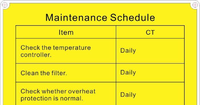
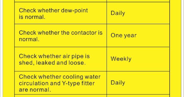
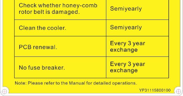
23 1.6 Maintenance Schedule Picture 1-7:Maintenance Schedule 23(92)
24 2. Structure Characteristics and Working Principle 2.1 Working Principle Dehumidifying: damp and hot air from dry material barrel is blown into rotor after cooled. Moisture from the air is absorbed by rotor and is then adsorbed by regeneration heating air. Two strands of airflow function on the rotor. And with the rotation, moisture from the air is absorbed and expelled after absorbed regeneration air to form stable low dew-point air, which is dried to the drying temperature and then is blown into material barrel to closed circle to dry material. Suction: material is absorbed into barrel from storage barrel or other storage containers. When the magnetic reed switch detects no material, suction motor runs to produce vacuum inside vacuum hopper. Raw material in storage barrels is absorbed into suction hopper due to air pressure difference. When the time is completed, suction motor stops. Raw materials drop into drying hopper barrel due to gravity. The dried raw material after dried from is taken out to the hopper with photosensor installed on moulding machine or other hopper form drying hopper barrel. 2.2 Relative Humidity and Dew-point Relative humidity: Relative air humidity means real vapor content to saturated vapor at the same temperature in percentage. Dew point: it means that temperature when the saturation vapor begins to dew. When the relative humidity is 100%, the ambient temperature is the dew point temperature. The more lower of dew point temperature (than the ambient temperature) is, the more less possible to dew, that also means the more drier the air is. The dew point will not be influenced by temperature, but influenced by pressure. 24(92)
25 2.3 Why Choose "All-in-One" Compact Dryer It is proved that the hygroscopic materials used in the plastics industry such as PC, PA, PBT, PET, Nylon, etc. cannot be dried effectively by conventional hot air drying systems because those systems depend on ambient conditions and are relatively inefficient in reducing moisture contents. These materials demand a steady low dew point dry air and a constant drying temperature, which guarantee final moisture content of 0.02% or even less. The SCD provides a closed-loop system with the dew-point of the dried air being down to -40 or even lower which accelerates moisture transferring from the plastic granules to the dry air. 2.4 Working Principle Picture 2-1:SCD Working Principle Picture 2-2:SCD-OP Working Principle (With plate heat exchanger) (Option) 25(92)
26 2.5 Dew-point Comparison Picture 2-3:Dew-point Comparison 26(92)
27 2.6 Drawing and Parts List Structural Drawing Names of Parts: 1. Conveying blower 2. Process blower 3. Process heater 4. Return-air filter 5. Regenerating heater 6. Honeycomb-rotor 7. Regenerating filter8. After cooler 9. Regenerating blower 10. Drying hopper 11. Material line 12. Vacuum line Vacuum line Material line (option for three-stage conveying) 15. Vacuum line (option for three-stage conveying) Picture 2-4:Structural Drawing 27(92)
(scd-20u/30h~40u/50h) 28(92)")
28 2.6.2 Assembly Drawing (Fully-integral design) (SCD-20U/30H~40U/50H) Remarks: Please refer to material list for specific explanation of the Arabic numbers in parts drawing. Picture 2-5:Assembly Drawing (Fully-integral design)(scd-20u/30h~40u/50h) 28(92)
29 2.6.3 Parts List (Fully-integral design)(scd-20u/30h~40u/50h) Table 2-1:Parts List (Fully-integral design)(scd-20u/30h~40u/50h) No. Description Part No. 20U/30H 40U/30H 40U/50H 1 Sight-glass window Sight-glass window fixing plate Hopper fixing plate Hopper top cover Insulated hopper Front door frame BY BY BY Front door plate 8 An electric cabinet door lock YW YW YW Cut-off valve type suction box BY BY BY Control box door Touch screen YE YE YE Main switch* YE YE YE Exhaust fan** YM YM YM Control box Front door plate (left) Front plate (left) Castor YW YW YW YW YW YW Process heater* BH BH BH Honeycomb YW YW YW Double-head screw BH BH BH Honeycomb upper cover BA BA BA Honeycomb bottom cover BA BA BA Right side plate Honeycomb mounting bracket Flange Top plate Rear plate lower cover Regen. heater* BH BH BH Cooler BW BW BW BW BW BW Copper insert core BH BH BH Regen. blower* BM BM BM (92)
30 No. Description Part No. 20U/30H 40U/30H 40U/50H 32 Process blower* BM BM BM Middle separating plate Conveying blower* BM BM BM Bottom plate Right bottom side plate Top standing pole Bottom standing pole Right upper side plate Rear plate at the bottom Rear plate at the top Rear plate cover Rear plate Rear plate bar Star knob YW YW YW Filter ADC18 ** YR YR YR Butterfly nut YW YW YW Filter 700/800G ** YR YR YR Gear motor YM YM YM Three-way valve BY BY BY Left upper side plate Inner side plate Belt regulator BH BH BH Transmission belt ** YR YR YR Spring YW YW YW * means possible broken parts. ** means easy broken part. and spare backup is suggested. Please confirm the version of manual before placing the purchase order to guarantee that the item number of the spare part is in accordance with the real object. 30(92)
31 2.6.4 Assembly Drawing (Fully-integral design) (SCD-80U/50H~230U/120H) Remarks: Please refer to material list for specific explanation of the Arabic numbers in parts drawing. Picture 2-6:Assembly Drawing (Fully-integral design) (SCD-80U/50H~230U/120H) 31(92)
32 2.6.5 Parts List (Fully-integral design)(scd-80u/50h~230u/120h) Table 2-2:Parts List (Fully-integral design)(scd-80u/50h~230u/120h) No. Description Part No. 80U/50H 120U/80H 160U/120H 230U/120H 1 Sight-glass window Sight-glass window fixing plate Hopper fixing plate Hopper top cover Insulated hopper Front door frame Front door plate An electric cabinet door lock Cut-off valve type suction box YW YW YW YW Control box door Touch screen YE YE YE YE Main switch* YE YE YE YE Exhaust fan** YM YM YM YM Control box BH Front door plate (left) Front plate (left) Castor YW YW YW YW YW YW YW YW Process heater* BH BH BH BH Honeycomb YW YW YW YW Double-head screw BH BH BH BH Honeycomb upper cover Honeycomb bottom cover BA BA BA BA BA BA BA BA Right side plate Honeycomb mounting bracket YW Flange Top plate Rear plate lower cover YE Regen. heater* BH BH BH BH Cooler BW BW BW BW BW BW BW BW Copper insert core BH BH BH BH (92)
33 No. Description Part No. 80U/50H 120U/80H 160U/120H 230U/120H 31 Regen. blower* BM BM BM BM Process blower* BM BM BM BM Middle separating plate Conveying blower* BM BM BM BM Bottom plate Right bottom side plate Top standing pole Bottom standing pole Right upper side plate Rear plate at the bottom Rear plate at the top Rear plate cover Rear plate YM Rear plate bar YE Star knob YW YW YW YW Filter 700/800G ** YR YR YR YR Butterfly nut YW YW YW YW Filter ADC18 ** YR YR YR YR Gear motor YM YM YM YM Three-way valve BY BY BY BY Left upper side plate Inner side plate Belt regulator BH BH BH BH Transmission belt ** YR YR YR YR Spring YW YW YW YW * means possible broken parts. ** means easy broken part. and spare backup is suggested. Please confirm the version of manual before placing the purchase order to guarantee that the item number of the spare part is in accordance with the real object. 33(92)
34 2.6.6 Assembly Drawing (Fully-integral design) (SCD-300U/200H~450U/200H) Remarks: Please refer to material list for specific explanation of the Arabic numbers in parts drawing. Picture 2-7:Assembly Drawing (Fully-integral design) (SCD-300U/200H~450U/200H) 34(92)
35 2.6.7 Parts List (Fully-integral design)(scd-300u/200h~450u/200h) Table 2-3:Parts List (Fully-integral design) (SCD-300U/200H~450U/200H) No. Description 35(92) 300U/200H Part No. 450U/200H 1 Sight-glass window Sight-glass window fixing plate Hopper fixing plate Hopper top cover Insulated hopper Front door frame Front door plate An electric cabinet door lock YW YW Cut-off valve type suction box Control box door Touch screen YE YE Main switch* YE YE Exhaust fan** YM YM Control box BH BH Front door plate (left) Front plate (left) Castor YW YW YW YW Process heater* BH BH Honeycomb YW YW Double-head screw BH BH Honeycomb upper cover YA YA Honeycomb bottom cover YA YA Right side plate Honeycomb mounting bracket Flange Top plate Rear plate lower cover YE Regen. heater* BH BH Cooler BL YW BL YW Copper insert core BH BH Regen. blower* BM BM Process blower* BM BM Middle separating plate - -
36 No. Description 300U/200H Part No. 450U/200H 34 Conveying blower* BM BM Bottom plate Right bottom side plate Top standing pole Bottom standing pole Right upper side plate Rear plate at the bottom Rear plate at the top Rear plate cover Rear plate YM Rear plate bar YE Star knob YW YW Filter 700/800G ** YR YR Butterfly nut YW YW Filter ** YR YR Gear motor YM YM Three-way valve BY BY Left upper side plate Inner side plate Belt regulator BH BH Transmission belt ** YR YR Spring YW YW * means possible broken parts. ** means easy broken part. and spare backup is suggested. Please confirm the version of manual before placing the purchase order to guarantee that the item number of the spare part is in accordance with the real object. 36(92)


37 2.6.8 Assembly Drawing (Semi-integral design) Remarks: Please refer to material list for specific explanation of the Arabic numbers in parts drawing. Picture 2-8:Assembly Drawing (Semi-integral design) 37(92)
38 2.6.9 Parts List (Semi-integral Design) Table 2-4:Parts List (Semi-integral Design)(SCD-600U/400H~750U/400H) No. Description Part No. 600U/400H 750U/400H 1 Castor YW YW Base frame welding ring Castor brake YW YW Front pole Right lower side plate Rear pole Upper side plate Side fixing beam Rear bottom plate Rear top plate Cover board Moisture outlet flange Air outlet flange Transmission belt** YR YR M16 Screw YW YW Washer YW YW Spring YW YW Honeycomb upper cover BA BA Honeycomb YW YW Rear fixing beam Two-head screw BH BH Honeycomb bottom cover BA BA Water distributor Rear middle beam Gear motor YM YM Side middle beam Rear middle beam Front middle beam Belt regulator pad BH BH Terminal block YE YE Capacitor YE YE Motor* BM BM Blower* YM YM Cooler BW BW Regenerated fan fixed beam (92)
39 No. Description 600U/400H Part No. 750U/400H 36 Cooler * YR YR Fixed beam of cooler Erect beam of base frame Bottom mounting beam Cross-beam of base frame Control trunk BH BH Filter** YR YR Filter cover Butterfly nut YW YW Filter** YR YR Upper door plate Hinge YW YW Bottom door plate Door interlock switch YE YE Control panel YR YR Short door bolt YW YW Pipe connector YR YR Right fixed leg Solenoid valve* YE YE Exhaust heater** YM YM Left fixed leg Feeding fan * BM BM EURO-material absorption box BY BY Regenerated heater* BH BH Leg reinforcement beam Cover board of housing Outer fixer Dry hopper drum Filter** YR YR * means possible broken parts. ** means easy broken part. and spare backup is suggested. Please confirm the version of manual before placing the purchase order to guarantee that the item number of the spare part is in accordance with the real object. 39(92)
40 Table 2-5:Parts List (Semi-integral Design) (SCD-900U/700H~1200U/700H) No. Description Part No. 900U/700H 1200U/700H 1 Castor YW YW Base frame welding ring Castor brake YW YW Front pole Right lower side plate Rear pole Upper side plate Side fixing beam Rear bottom plate Rear top plate Cover board Moisture outlet flange Air outlet flange Transmission belt** YR YR M16 Screw Washer Spring YW YW Honeycomb upper cover BA BA Honeycomb YW YW Rear fixing beam Two-head screw BH BH Honeycomb bottom cover BA BA Water distributor Rear middle beam Gear motor YM YM Side middle beam Rear middle beam Front middle beam Belt regulator pad BH BH Terminal block YE YE Capacitor YE YE Motor* BM BM Blower* YM YM Cooler YR YR Regenerated fan fixed beam Cooler * YR YR (92)
41 No. Description 900U/700H Part No. 1200U/700H 37 Fixed beam of cooler Erect beam of base frame Bottom mounting beam Cross-beam of base frame Control trunk BH BH Filter** YR YR Filter cover Butterfly nut YW YW Filter** YR YR Upper door plate Hinge YW YW Bottom door plate Door interlock switch YE YE Control panel YR YR Short door bolt YW YW Pipe connector YR YR Right fixed leg Solenoid valve* YE YE Exhaust heater** YM YM Left fixed leg Feeding fan * BM BM EURO-material absorption box BY BY Regenerated heater* BH BH Leg reinforcement beam Cover board of housing Outer fixer Dry hopper drum Filter** YR YR * means possible broken parts. ** means easy broken part. and spare backup is suggested. Please confirm the version of manual before placing the purchase order to guarantee that the item number of the spare part is in accordance with the real object. 41(92)
42 Filter & Pressure Regulating Valve Drawing Parts list: 1. Pressure adjusting knob 2. Pressure gauge 3. Cup 4. Water outlet Picture 2-9:Filter & Pressure Regulating Valve Drawing 42(92)
43 Heater Parts name: 1. Electric wood cover 2. Pipe heater 3. Heater wrapper sheet 1 4. Heating tank 5. Heater cover plate 6. Heater wrapper sheet 2 7. Heater fixed seat Picture 2-10:Heater 43(92)
44 Honeycomb Picture 2-11:Honeycomb Parts Drawing (SCD-900U/700H 1200U/700H) 44(92)
45 Parts List of Honeycomb (SCD-900U/700H 1200U/700H) Table 2-6:Parts List No. Description Part No. No. Description Part No Honeycom flange 2.5 honeycomb flange - 10 Flat washer Spring YW Lower cover - 12 Hex nut M16-4 Honeycomb shaft - 13 Hexgon socket head cap screw M8 5 Sychronous belt YR Gear motor YM Synchronous pulley YR Belt adjustor - 7 Honeycomb YW Mounting plate of gear motor 8 Double-end screw BH Locating tube - 9 Upper cover - 18 Synchronous pulley - * means possible broken parts. ** means easy broken part. and spare backup is suggested. Please confirm the version of manual before placing the purchase order to guarantee that the item number of the spare part is in accordance with the real object (92)
46 Material Stage Bin of Optical Grade MST-80U-OP Name of components: 1. Brake-type universal floor stand 2. Free-style universal floor stand 3. Floor stand 4. Inner hexagonal screw column Elbow 6. Seal ring Fast pipe connector 8. Feed port Three way 10. Material storage tank 11. Cover back button Flat gasket 13. Spring gasket 14. Acorn nut Fastener for sight glass window 16. Acryl 17. Fastener for sight glass window 18. Nut 19. Connection pipe Ball valve 21. Acorn nut 22. Spring gasket 23. Flat gasket 24. Cover back button Snap hook 26. Material storage tank fastener 27. Material storage tank top 28. Filter 1 fastener 29. Filter Filter cover Flat gasket 32. Star nut 33. Inner hexagonal screw column 34. Square aluminum handle 35. Pin Picture 2-12:Material Stage Bin of Optical Grade MST-80U-OP 46(92)
47 High-efficiency Filter HEPA Name of components: 1. Brake-type universal floor stand 2. Free-style universal floor stand 3. Floor stand 4. Clamp tube 5. Metric taper thread 6. Connector 7. Bottom cover of filter 8. High-efficiency filter 9. Middle-efficiency filter 10. Top cover of filter 11. Screw shaft 12. Star screw 13. Low-efficiency filter 14. Filter cover 15. Stainless steel washer Picture 2-13:High-efficiency Filter HEPA 47(92)
48 Important notices for using SHR-CP-3U Name of components: 1. Top cover 2. Screener fastener 3. Screener 4. Flat gasket M6 5. Inner hexagon column screw M Glass pipe upper flange 7. Glass pipe packing 8. Glass tube 9. Flange connection shaft 10. Inner hexagon column screw M Flat gasket 12. Glass tube lower flange 13. Non-return flap 14. Bottom cover board 15. Base 16. Sight-glass 17. Sight-glass iron sheet 18. Supporting frame 19. Sensor fixing plate 20. Sensor 21. Snap hook 22. Snap hook fixing plate Picture 2-14:Important notices for using SHR-CP-3U 48(92)

49 Main Electrical Components Description Overload Relay At delivery, the overload relay is set for mannual reset. (The reset button pointing to H). Manually reset the relay at the tripping of the switch. When motor overload occurs, stop the machine, then check and solve the problem. After that open the door of control box, press down the reset button of overload relay (if you can not press down the reset button, wait for one minute.) Picture 2-15:Overload Relay 1) Terminal for contact coil A2. 2) Setting current adjusting scale. 3) Reset (blue). H: manual reset A: automatic reset 4) Switch position indication (green). Tripping of a manual-resetting is indicated by a pin projecting from the front plate. 5) Test button (red). 6) Auxiliary contact terminals shown in NC and NO contacts are shown in position and respectively. 7) Main circuit connection No. must be correspond with terminal Number of contactor. 49(92)
50 2.7 Operation Procedures Before connecting electrical power source, the main power switch must be turned to OFF position. After the machine connected with power source, turn the main power switch to ON position. According to your applications, operate drying and loading system respectively Operation Regulations Picture 2-16:Operation Regulations 1) Do not use keen-edged object instead of hands to operate the touch screen, and prevent violent collision of it. 2) In a dry environment, static electricity may accumulated on the touch screen. Use a metal wire to discharge it before operating. 3) Use alcohol or eleoptene to wipe off the pollutants on the screen. Other solvent may cause the color of the screen to fade out. 4) Do not tear down any parts of the touch screen or take away any PCBs attached to it. 50(92)
51 2.7.2 Description of touch screen Picture 2-17:Description of touch screen A:Display B:Touch panel C:LED status indicator Touch panel appear error Table 2-7:Touch panel information LED indicator light Green (light) Orange (light) Orange (shine) Red (light) No shine XBT GT State Work welled Backlight lamp burning During software startup Power status Power break off Screen operation flow Table This operation system consists of eight (8) main screens: Drying Monitoring, Conveying Monitoring, Temperature Parameter, Conveying Parameter, Time Setting, Alarm Fault Records, and On-line Help. They are shown as below: 51(92)

52 Picture 2-18:Screen operation flow Table Menu particular 1) System Default System When the system is connected with power source, the initial default screen will display as shown below. By touching the button of "English" or "Chinese" to select either English or Chinese languages in order to login "Drying Monitoring" screen. 2) Drying MonitoringScreen Picture 2-19:System Default System Drying Monitoring screen is shown as below: 52(92)

 Set drying temp. Touch the preset value of process temp. A numerical keypad will appear.")
, the drying temperature is independently controlled by each temperature controller under the")
53 Picture 2-20:Drying Process Screen A. Operation of the menu Start the system: Touch the start switch to make it show ON, then the system starts. Stop the system: Touch the start switch again to make it show OFF, then the system stops running. (Attention: In order to prolong the life of honeycomb-rotor, it s necessary to delay the stop time of the rotor for cooling. Set the delayed time at about 2~3 minutes. Please see more details of setting on the time parameter setting screen.) Set drying temp. Touch the preset value of process temp. A numerical keypad will appear. Use the keypad to input temperature values. If it s the system above model one-to-two (consists of a dehumidifier and more than two drying tanks), the drying temperature is independently controlled by each temperature controller under the drying tank. By then, the drying temperature for each drying tank is set via corresponding temperature controller. In addition, turn on the switch besides the temperature controller first. These parameters only take effect when it s equipped with drying heater. Touch the preset value of regenerating temp. A keypad will appear. Use the keypad to input temperature values. 53(92)

54 Note! Drying temp. and regenerating temp. value are set within certain limits. Drying temp. should be set between 0 ~200 and regenerating temp.should be set between 130~180! The regenerating temp. value is already set to be 130 or 180 when produced. Please don't reset it if no special occasion. B.Five Functional Keys: Home page: Press this button to enter into the home page screen. Conveying Monitoring: Press this button to enter into "Conveying Monitoring " screen. Parameter Setting: Press this button to enter into "Parameters Setting" screen. (Input correct password to log-in.) Alarm Display: When system appears warning message, press this button to check the details and related help message. Help: Press this button to enter into Help Menu screen. 3) Conveying Process Screen By touching the "Conveying Monitoring" button at the bottom of "Drying Monitoring " screen, it will enter into Conveying Monitoring screen as shown below: Picture 2-21:Conveying Monitoring Screen 4) Temperature Parameters Setting Touch parameter setting button at the bottom part of Conveying Monitoring 54(92)


55 Screen. Then, the system will pop out a password window for inputing user name: Shini, and passwords Press "ENTER" button to confirm. By then, the numeric keypad will turn off and return to the password window. After that, press Sure and "Return" key by turn to go back to the drying monitoring or conveying monitoring screen. By pressing the "parameter setting" button again, you can log in and change parameters. Picture 2-22:Temperature Parameters Setting 1 Warning! Please keep this password securely and safely. If the password is missing, then the operator won't be able to log into the system parameter setup screen. It is better to let this password known only by system administrator or senior operator. After input correct password, the screen will show the following "temperature parameter setting" screen. Shown as below: Picture 2-23:Temperature Parameters Setting 2 55(92)


56 Drying and Regeneration Temperature Parameter Setting: By touching "PID" button, the system will pop up the temperature control PID screen in which three parameters can be set, such as: Proportion, Integral Time and Differential Time. Picture 2-24:Drying & Regeneration Temperature Control Parameters If to change any parameters, it s only need to touch the corresponding "input area" and then a numeric keypad will pop up. Input a new parameter and press "ENTER" to confirm the new parameter. The max. and min. display area of the numeric keypad shows the present max. and min. setting value. If the setting value exceeds the limits, it would be invalid to press "ENTER". P.I.D. control: When temperature control is inaccurate, users can manually adjust temp. control parameters to achieve the best temperature control effect. 56(92)
57 Adjustment of Proportion (P) Table 2-8:Adjustment of Proportion (P) Adjustment of Integral Time (I) Table 2-9:Adjustment of Integral Time (I) Adjustment of Differential Time (D) Table 2-10:Adjustment of Differential Time (D) 5) Conveying Parameter Setting Input the right user name and password to enter into the parameter setting screen. Then, touch the "Conveying Parameter" button to enter into the 57(92)

58 parameter setting screen. Parameters include Conveying Time, Loading Failure Counter and Shut-Off time can be set according to actual requirements. Picture 2-25:Conveying Parameter Setting Warning! All parameter default setting is done before delivery. Under normal condition, please DO NOT adjust the setting values, otherwise it could cause blockage of the material conveying line. Material feeding time (Unit: Second) When system detects material shortage, it will count down for 3 seconds. After that,plc will send out signals to start the suction motor for feeding the molding machine. At the same time, it will time the loading time. When the loading time is up, it will stop loading and add 1 to material loading times. Times of material shortage For feeding the molding machine, it will limit the material loading times if there is still a material shortage signal. When it's up to the set loading times, the system will stop feeding the machine. Furthermore, it will send out an alarm signal of material loading fault to remind users to check whether the storage tank is lack of material or other faults caused loading failure. Shut-off time (Unit: Second) 58(92)
 Time Setting A.")

59 Shut-off time refers to opening time of relative shut-off valve. The longer the shut-off time, the more material will be discharged. Warning! Shut-off time should not be set for too long. Otherwise, some material will remain in the material line, which will affect the material drying effect. 6) Time Setting A. Touch the "Time Setting" button to enter into Time Setting screen as shown below: Picture 2-26:Time Setting 1 Note! After setting the auto-start time, the button 1 will be on. By then, the machine will run according to the set time. B. If there are some deviations with the system date and time, touch the Real-time clock setting to enter into the time setting interface to modify the system time. The screen is as below: 59(92)


60 Picture 2-27:Time Setting 2 After touching any parameter setting menu, a numeric keypad will appear. Input each parameter and then press SET. Then, the new setting comes into effect. The setting can be cancelled by pressing cancel. 7) Alarm Fault Records Touch "Alarm Display" button under the bottom of "Drying Process" screen or "Conveying Process" screen to enter into Alarm Fault Records screen. The screen is shown as below: Picture 2-28:Alarm Fault Records 1. When alarm fault records cover more than displaying space, touch "Up" or "Down" keys to read more records. 2. According to the alarm information, the operator could get the troubleshooting information from the instruction book. 3. Press "EXIT" button to exit from this screen. 4. System Alarm Information List 60(92)
61 Table 2-11:System Alarm Information List Alert message Results Possible causes Power phases are storage. Process blower Overload. Regenerating blower overload. Conveying blower overload. No.1 receiver suction problem No.2 receiver suction problem No.3 receiver suction problem Process temperature overheat Regenerating temp. overheat Return air temp. overheat Process temp. Thermople broken Regenerating temp. Thermocouple broken Return air temp. Thermocouple broken Rotor speed is not proper PLC is not under operation mode System cannot operate, and the visible alarm is flickering. Dehumidifier does not work and the visible alarm is flickering. Dehumidifier does not work and red alert light is flickering. Material conveying stops and the visible alarm is flickering. No.1 receiver stop suction function and the visible alarm is flickering. No.2 receiver stop suction function and the visible alarm is flickering. No.3 receiver stop suction function and the visible alarm is flickering. Dehumidifier does not work and the visible alarm is flickering. Dehumidifier does not work and the visible alarm is flickering. Dehumidifier does not work and the visible alarm is flickering. Dehumidifier does not work and the visible alarm is flickering. Dehumidifier does not work and the visible alarm is flickering. Dehumidifier does not work and the visible alarm is flickering. Dehumidifier does not work and the visible alarm is flickering. System does not work properly. Shortage of main power phases. Incorrect motor overload setting, or motor burns out. Incorrect motor overload setting, or motor burns out. Incorrect motor overload setting, or motor burns out. Storage tank lacks material, suction probe problem, parameter wrongly setting, shut-off valve damaged. Drying hopper lacks material, suction box problem, parameter wrongly set, shut-off valve damaged. Drying hopper lacks material, suction box problem, parameter wrongly set, shut-off valve damaged Temperature control parameter wrongly setup, touching pad is malfunction, process heating problem. Temperature control parameter wrongly set, touching pad is malfunction, regenerating heating problem. Insufficient cooling water. Thermocouple disconnected or bad contact. Thermocouple disconnected or bad contact. Thermocouple disconnected or bad contact. Rotor driving motor burnt, belt broken, speed controller damaged, or incorrect rotor speed monitoring parameter setting. PLC on/off switch is not in RUN mode. Note:1) Overload Relay reset: Open control box, press "RESET" button on the corresponding overload relay. 2) Rotor Failure Alarm reset: Turn off the Drying Switch and then turn it "ON" again. 3) Over Temperature Alarm reset: Turn off the Drying Switch and then turn it "ON" again after the temperature drops down. 61(92)


62 8) Help Screen Touch "Help" button under the bottom of Drying Monitoring or Conveying Monitoring screen to enter into system help menu screen. Touch the menu button to get corresponding help message. Picture 2-29:Help Screen 62(92)
 Power cable and earth connections should conform with your local regulations. 3) Use independent electrical wires and power switch.")
63 3. Installation Testing 3.1 Attention 1) Make sure voltage and frequency of the power source comply with those indicated on the manufacturer nameplate, attached to the machine. 2) Power cable and earth connections should conform with your local regulations. 3) Use independent electrical wires and power switch. Diameter of electrical wire should not be less than those used in the control box. 4) The power cable connection terminals should be tightened securely. 5) The machine requires a 3-phase 4-wire power source, connect the power lead (L1, L2, L3) to the live wires, and the earth (PE) to the ground. 6) Power supply requirements: Main power voltage: +/- 10% Main power frequency: +/- 2% 7) The cooling water pressure is 3~5 kgf/cm 2,the pressure gap between the inlet water and the outlet water is 3~5 kgf/cm 2, and the cooling water temperature is 10~30. 8) Refer to the electrical wiring diagram to complete the electrical Installation. Picture 3-1:Installation drawing Notes! Keep the machine 2m from the combustible distance. 63(92)
")
64 Picture 3-2:Schematic drawing of installation (Fully-integral design) Picture 3-3:Schematic drawing of installation (semi-integral design) 64(92)
65 3.2 Honeycomb-rotor What is Honeycomb-rotor The main body of the honeycomb-rotor is a honeycomb, made by ceramic fibre and organic additives, sintered under high temperature with molecular sieve and silica gel, to be strongly bonded together and form a solid and hard surface. Not like common molecular sieve, which will produce dusts and fines to pollute raw materials when aging or become saturated requiring regular replacement, honeycomb-rotor offer unlimited long life and can be cleaned when it is polluted. The moisture of return air is quickly absorbed by numerous tunnels before coming out of the rotor to form low dew-point air. At the same time, regenerating blower takes dry air into the honeycomb-rotor from an opposite direction to regenerate the rotor. Picture 3-4:Honeycomb rotor Installation of the Rotor 1) The upper and lower lid of honey-comb should install Teflon gasket (Fig. 1). 2) Use 4 screws to fix the rotor base on the machine frame firmly, and then install the shaft accordingly (Fig. 2). 3) Install the gearmotor and transmission gear (Fig. 4). 4) Install and fix the main support screws (Fig. 3). 5) Fit the transmission belt in proper position (Fig. 6). 6) Install the honeycomb-rotor (Fig. 9) and transmission belt (Fig. 12). 7) Fix the rotor top cover (Fig. 8). 65(92)
.")

.")


66 8) Fit all springs and tighten the screws (Fig. 7). 9) Install both the transmission belt (Fig. 13) and belt tension regulator (Fig. 14). 10) Install micro-switch and fixed board firmly (Fig. 10) Picture 3-5:Installation of the Rotor 66(92)

 Warning!")


67 3.3 Heater Assemblies 1) Install the heating pipe in the heater. 2) Fix the heater into the housing. (See right picture) Warning! Hot surfaces could burn hands. Take care of high temperature! This label should be stick to the shell of heater. 1 2 Picture 3-6:Heater Assemblies 67(92)
 Install the blower on the Machine frame. Picture 3-7:Installation of Blowers 3.4.2 Regeneration Blower 1) Fix inlet/outlet flange of blower, and tighten 4 screws securely.")
68 3.4 Installation of Blowers Drying Blower 1) Fix inlet/outlet flange of blower, and tighten 4 screws securely. 2) Connect the blower with electrical source. 3) Install the blower on the Machine frame. Picture 3-7:Installation of Blowers Regeneration Blower 1) Fix inlet/outlet flange of blower, and tighten 4 screws securely. 2) Install the blower on the machine frame. 3) Connect the blower with electrical source Conveying Blower 1) Fix inlet/outlet flange of blower, and tighten 4 screws securely. 2) Connect the blower with electrical power source. 3) Install the blower on the machine frame. 4) Fix the three-way valve (See Figure. 1). 5) Install the solenoid valve, and then tighten 2 screws on the machine frame (See Figure. 2). 1 2 Picture 3-8:Conveying Blower 68(92)
 Pull the black pressure adjusting knob 1 upward and rotate it, observe the pressure gauge 2, generally a 0.5 Mpa pressure is advisable. 3) Push back the black knob 1. 3.4.")
69 3.4.4 Installation of Drying Hopper 1) Install drying hopper on the machine frame. 2) Fix the shut-off valve adaptor on the suction box. 3) Install the shut-off valve on the suction box Filter & Pressure Regulating Valve 1) Switch on the air source. 2) Pull the black pressure adjusting knob 1 upward and rotate it, observe the pressure gauge 2, generally a 0.5 Mpa pressure is advisable. 3) Push back the black knob EGO The EGO value has been setting before out factory, Don't modify it Cyclone Dust Collector Picture 3-9:EGO Picture 3-10:Installation Diagram of Cyclone Dust Collector 69(92)
70 Cyclone Dust Collector Installation steps: 1. Connect 1 and 5 with a heat-resistant duct and fixed both the ends with stainless steel tube. 2. Connect 2 and 3 with a heat-resistant duct and fixed both the ends with stainless steel tube. 3. Connect 4 and 6 with a heat-resistant duct and fixed both the ends with stainless steel tube Oil Filter Picture 3-11:Installation Diagram of Oil Filter Oil filter installation steps: 1. Screw the oil filter on the top plate of the honeycomb dehumidifier. 2. Connect 1 and 2 with a heat-resistant duct and fixed both the ends with stainless steel tube. 3. Connect 3 and 4 with a heat-resistant duct and fixed both the ends with stainless steel tube. 4. Connect 5 and 6 with a heat-resistant duct and fixed both the ends with stainless steel tube. 70(92)
71 3.4.9 Plate Heat Exchanger Picture 3-12:Plate Heat Exchanger over Figure Each part is connected by heat-resistant air pipes and fixed by stainless steel pipes as shown in the diagram. 71(92)
72 4. Application and Operation Turn on the main switch to connect power supply on the control panel. 4.1 Panel Operation 1) Open the main switch. 2) Press "RUN/STOP "key to start loading. 4.2 Temperature Setup 1) The setup number will flicker after pressing "SET" key, add or decrease temperature by pressing key. 2) Press "ENTER" key to confirm the input value. 4.3 PID Auto-tuning Setting 1) Press SET and the digits flash. At this time press SET and Enter meanwhile for 1.5 seconds to enter auto-tuning mode. Then two values of At and Present temperature will display alternatively in PV and the set temperature value displays in SV till auto-tuning is finished. After that, system goes back to the normal operation directly. 2) If auto-tuning setting could not be finished within 1 hour, the parameters will not be altered and system goes back to normal operation. 3) Pressing ON/OFF to go back normal operation amid automatic calculation would not alter the original parameters. 4.4 Intermittent Running Setup Drying periods(0-on) Stop periods(0-off) 1) Press "SET" key to change temp. setup value into time setup value,press "TEMP/TIMER" key to enter into setup mode, at this time "SV/setup value" flickers,"pv/setup value"displays"0-on". 72(92)
 Press \"ENTER\" to confirm the input time value and enter into \"0-OFF\" time setup items, then repeat step 2.")
 Cancel intermittent running by entering 00.")
73 Picture 4-1:Intermittent Running Setup 1 2) PV displays "0-ON" to stand for drying periods. "0-OFF" stands for machine stop time. Press key to add or decrease time value of "SV/setup value". Each press of can add or decrease 15 mins set time. 3) Press "ENTER" to confirm the input time value and enter into "0-OFF" time setup items, then repeat step 2. Picture 4-2:Intermittent Running Setup 2 Note:If set 0-ON as 04:00, 0-OFF as 05:00, which means drying periods is 4 hours stop time is 5 hours,then working for 4 hours and being stopped for 5 hours and repeat this so long. 4) Cancel intermittent running by entering at "0-ON" or "0-OFF" press "ENTER" to confirm input value after time setup and enter into time setup items from "1-ON" "week-on". 73(92)


 Press key to add or decrease the time value in")
74 4.5 Weekly Time Start Setup Picture 4-3:Intermittent Running Setup 3 1) After setting intermittent operation type, here comes Weekly Time. Press key to add or decrease the time value in "SV/setup value " from "1-ON". Press "ENTER" to confirm the input value and comes into the time setup items of "1-OFF" "MON-OFF". Picture 4-4:Weekly Time Start Setup 1 2) Press key to add or decrease the time value in "SV/setup value " from "1-OFF". Press "ENTER" to confirm the input value and comes into the time setup items of "2-ON""TUE-ON". Picture 4-5:Weekly Time Start Setup 2 74(92)
 Setup all the \"ON\" to 00:00 if it is not for weekly time start/stop. Note: 1. F-20 functions as an password lock,hold on\"set\"till the\"pv\"displays F-20. 2.")
75 3) Do the same setup again and again to setup the ON/OFF time from Monday to Sunday. Picture 4-6:Weekly Time Start Setup 3 4) Press "SET" key to back to normal status, after finish all the setup. 5) Setup all the "ON" to 00:00 if it is not for weekly time start/stop. Note: 1. F-20 functions as an password lock,hold on"set"till the"pv"displays F Press key and only after input 0021 in the SV,can you press "ENTER"to come into F-03 and other settings,so F-20 functions as an passwordlock for entering into next parameters setup, which prevents the modification from unprofessionals. Picture 4-7:Weekly Time Start Setup 4 3. F-03 stands for the selection of temperature unit. Press to shift between / then press ENTER to confirm. 4. F-04 is data lockup function, press key to shift between OFF / LOCK, LOCK is for locking up information,not able to input or change any data: OFF is for lockup cancellation. 75(92)

76 Picture 4-8:Weekly Time Start Setup 5 5. F-05 stands for the function of temperature protection. Alarm will be launched if actual temperature were equal to or higher than the addition of setting temperature value and setting value. This temperature range is between 0 to 50, and default value is Present Time Modification 1) Repeat the above steps until PV displays "TIME" to stand for present time. 2) Press key to add or decrease time. 3) Press "ENTER" key and PV displays "DAY" to stand for week days. 4) Press key to add or decrease days. 5) Press "SET" key to back to normal status after finish all the setup. 4.7 Weekly Time Start 1) Activate the weekly time start after finish the time setup and the present time setup. 2) Press "AUTO" key at working or stop status to preset the time start/stop, the "PV" will display the time and temp. alternatively. 3) Press "AUTO" again if want to cancel that weekly time setup. 4.8 Lock Setup Way 1) Press "SET" key down and release it till "PV" displays F-20. 2) Press key to make "SV" to 0021, then press "ENTER" key,the "PV" will display F (92)
77 3) F-04 are for LOCK function selection,press key to select LOCK or OFF. 4) Press ENTER or "SET" key after setup. 5) If select LOCK,the "SV" will display "LOCK" when pressing "SET" key, which means the parameters have been setup and not accessible to any change. 4.9 The second level of Advanced Setting 1) Enter the first level of advanced setting and press SET and Enter meanwhile for 3 seconds till F-06 displays in PV.. 2) Press to set SV into 0003 and press Enter, at this time F-06 displays in PV. 3) Now pressing can alter value, press Enter to input after confirming then jump to F-07. 4) If you want to leave the function setting, just press SET. 1. F-06 stands for the passwords of second level. 2. F-07 stands for proportional band of heating side (P); it is a preset value before delivery. 3. F-08 stands for integration time of heating side (I); it is a preset value before delivery. 4. F-09 stands for differential time of heating side (D); it is a preset value before delivery. 5. F-10 stands for switch cycle of heating side; its preset value is 15 sec. 6. F-16 stands for power deliver delay time of heater, it is adjustable, the unit is Sec.. (Heating begins after blower activates Delay Setup Time) 7. F-17 stands for blower power-off delay time, it is adjustable, the unit is Sec.. (Press ON/OFF and heating stops. After blower starts delay setup time, machine stops running to avoid high-temp..) 8. F-18 stands for the protection of maximum temperature. Its setting range is 77(92)
78 140~250. (If drying temp. exceeds set value, machine halts and alarm sounds to avoid overheat caused by faults.) 9. F-19 stands for microswitch timeset of honeycomb rotor. OFF functions as shut-off and ON functions as open. The setting range is 0~9999 with the unit is Sec.. (Rotor starts running to monitor time and set time should be less than that of rotor rotation of one circle. Microswitch can be reset periodically to monitor if honeycomb runs normally.) 4.10 Wrong Codes Remark Table 4-1:Wrong Codes Remark Wrong codes Remark E-01 Break line of thermocouple E-02 Power reverse phase, default phase E-03 Overload of blower E-04 Drying temp. exceeds EGO set value E-05 Drying temp. exceeds max. set value E-07 Overheat protection (PV SV plus set value, alarm sounds) E-08 Memory errors E-09 Running fault of honeycomb-rotor E-10 Regenerative temp. exceeds EGO set value E-11 Insert errors of thermocouple +, - E-12 PID auto-tuning errors 4.11 Operation of Conveying System 1) Press once to set the suction time of the hopper 1. Press once to set the suction time of the hopper 2. Press three times to set the time for opening the valve. 2) Change the required time with key. 3) Press RUN/STOP once, hopper 1 turned on but hopper 2 turned off. Press RUN/STOP twice, both hopper 1 and 2 turned on. Press RUN/STOP three times, hopper 1 turned off but hopper 2 turned on. 78(92)


79 Press RUN/STOP four times, both hopper 1 and 2 turned off Operation of Dehumidifying System Open up the control box, and find the temperature controller, adjust the scale to set the regeneration temperature: Picture 4-9:Temperature Controller Note: 1. F-20 functions as an password lock, hold on "SET" till the "PV" displays F Press key and only after input 0021 in the SV, can you press "ENTER" to come into F-04 and other settings, so F-20 functions as an passwordlock for entering into next parameters setup, which prevents the modification from unprofessionals. Picture 4-10:Password Lock 1 3. F-04 is data lockup function, press key to shift between OFF/LOCK, LOCK is for locking up information, not able to input or change any data; OFF is for lockup cancellation. 79(92)

80 Picture 4-11:Password Lock 2 4. Press "ENTER" key to confirm the input value and comes into next function item "F-05". 5. Because the first function key has two items,so jump into "F-04" after input "F-05", for exiting the function setting, press "SET" key Installation for Dewpoint Monitor 1) Use blade to cut off the film and outline the reserved hole site on the SCD control panel. Picture 4-12:Hole Site 2) Check if there are complete parts for dewpoint monitor including: Dew-point monitor Dew-point transmitter assembly (dew-point detector, detection cable, washer and installation guide) Copper joint, installation seat for dew-point monitor 80(92)


81 Picture 4-13:Parts of Dew-point Monitor 3) Dismantle the copper joint of original machine and replace it with installation seat for dew-point monitor. Then dismantle straight form bushing from copper joint of original machine and install it on the installation seat, and connect copper pipe with straight form bushing. Picture 4-14:Copper Joint Assembly of Original Machine Picture 4-15:Installation Seat 81(92)


 Match dew-point")

82 4) Install dew-point transmitter assembly to copper joint. Picture 4-16:Installation for Transmitter 5) Connect signal wire. Particular shape of signal wire joint would avoid the wrong insert and connection. Picture 4-17:Connection of Signal Wire 6) Match dew-point monitor with holes on the panel and fix the installation. Picture 4-18:Installation for Dew-point Monitor 82(92)


83 7) Connect signal wires of the transmitter and power lines of dew-point monitor with the according terminals. Connet contact No.1 and No.2 with power, supply is 220VAC. Contact No.3, No.4 and No.5 are idle. Connect contact No.6, No.7 and No.8 with the signal of transmitter. (C- Connects contact No.6, C+ connects contact No.7 and wire No.9 connects contact No.8. Transmitter conection (White and blue wire connect wire No9, black wire connect C- and gray wire connect C+) Picture 4-19:Connection of Dew-point Monitor 83(92)
84 5. Trouble-shooting Symptom Possible causes Actions taken 1. Return air temperature too high 1. Check cooling water temperature (below 40 ) 2. Abnormal rotation speed 2. Adjust electric conveyer (Default value is 4) 3. Abnormal setting of regenerating temperature 3. Launch temperature setup screen, set regenerative temperature again 4. Rotation wheel blocked 4. Clean or clean rotor Alarm light for high dew point bleaks 5. Filter is blocked 5. Clean or replacement 6. Leakage of heat-resistant hose 6. Check pipe and connector 7. Operating time is less than 30 minutes 7. Wait until 30 minutes later for confirmation 8. Rotation wheel is not working 8. Check motor, conveyer, belt is damage or not 9. Motor's direction is wrong 9. Check motor's direction 10. System drying capacity insufficient 10. Replace with a large system System cannot operate Long lack time but suction fan not work 11. Honey-comb upper/lower lid is leaking 1. Main AC power supply unconnected 11. service or change the seal components 1. Close main AC power supply 2. Put timer switch into ON status 2. Reset timer button and restart again 3. Motor overload or Phase reverse 1. Main AC power source unconnected or touch button is not in ON position 2. Funnel's sensor, micro switch are bad contact 3. Check close-loop, regenerative motor and AC power source are connected correctly 1. Close main AC power source 2. Adjust or replace 3. Signal cable is broken 3. Re-connect or replace 1. Heat relay off load 1. Check reason and reset Motor does not run Material is full but suction fan still working 2. Connector is not working 2. Check it is burnt out or not 3. Power source lack of phase or motor is burnt out 1. LED sensor or micro switch is On status 3. Check and replace 1. Adjust or replace 2. Signal's cable is broken 2. Check signal cable 3. Mechanical problem or connector point is melt 3. Repair or Replace 4. PLC problem 4. Check and replace 84(92)
85 Symptom Possible causes Actions taken 1. Material is used up 1. To add more materials Continuous running but cannot fill up funnel 2. Pipe is leakage 2. Repair or replace 3. Filter is blocked 3. Clean 4. Diaphragm valve or shutoff valve is closed 5. Motor's blade problem 5. Check and repair 4. Check diaphragm valve or shutoff valve's pressure, electric valve may be burnt out, circuit is well connected or not 85(92)

86 6. Maintenance and Repair 86(92)
87 6.1 Filter & Pressure Regulating Valve Filter & Pressure Regulating Valve Drawing Parts list: 1. Pressure adjusting knob 2. Pressure gauge 3. Cup 4. Water outlet Picture 6-1:Filter & Pressure Regulating Valve Drawing Filter & Pressure Regulating Valve Operation steps 1) Switch on the air source. 2) Pull the black pressure adjusting knob 1 upward and rotate it, observe the pressure gauge 2, generally a 0.5 Mpa pressure is advisable. 3) Push back the black knob Air Filters Please periodically clean the dust on the air filters, once per week. Cleaning steps: 1) Take out the air filter carefully. 2) Blow off the dust on the air filter screen and the cover with pressure air. 3) Wipe off the barrel wall of air filter with cloth. 4) After cleaning, place all parts in reversed order carefully. 87(92)

, by removing surface dust.")

 Ball bearing, oil seal and sound-proof are belonging to consumable")
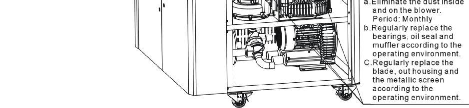
88 Picture 6-2:Air Filters Note! Don't let sundries fall into the barrel, when taking out the air filter. 6.3 Blower Motors 1) To clean blower both internal and external parts (especially the fan cooling path), by removing surface dust. If more dusts are accumulated, it will cause deficiency for ventilation, temperature rising up, blower power reduced, vibration increased and so it will cause machine broke down. 2) Ball bearing, oil seal and sound-proof are belonging to consumable parts and so it has a life period and requires regular replacement. Picture 6-3:Blower Motors 88(92)
SDD Series Dehumidifying Dryer
 SDD Series Dehumidifying Dryer Date: Nov. 2014 Version: Ver.D (English) Contents 1. General Description...9 1.1 Coding Principle...10 1.2 Feature...10 1.3 Technical Specifications...12 1.3.1 Specifications...12
SSM-U Series Storage Mixers
 SSM-U Series Storage Mixers Date: Oct, 2013 Version: Ver.A (English) Contents 1. General Description... 7 1.1 Coding Principle... 8 1.2 Feature... 8 1.3 Technical Specifications... 10 1.3.1 Technical
Portable honeycomb matrix compact dryer, with loading, combines dehumidifying plastic resin and conveying into a single unit.
 Portable honeycomb matrix compact dryer, with loading, combines dehumidifying plastic resin and conveying into a single unit. Comet s CCD series compact honeycomb matrix dryers incorporate drying and dehumidifying
SDL-U-HD Series Heatless Dehumidifying Compact Dryer
 SDL-U-HD Series Heatless Dehumidifying Compact Dryer Date: Nov. 2014 Version: Ver.B (English) Contents 1. General Description... 7 1.1 Coding Principle... 8 1.2 Feature... 8 1.3 Technical Specifications...
SCAD-U Series Compressed Air Dryer
 SCAD-U Series Compressed Air Dryer Date: Jul. 2014 Version: Ver.B (English) Contents 1. General Description... 7 1.1 Coding Principle... 8 1.2 Feature... 8 1.3 Technical Specifications... 11 1.3.1 Specifications...
2.2 Drawing and Parts List
 2.2 Drawing and Parts List 2.2.1 Structural Drawing (SHD-20U~750U) Names of Parts: 1. Main switch 2. Insulated layer 3. Blower 4. Material storage tank 5. Electric heating box 6. Control box 7. Overheat
STM-PW Series High Temp. Water Heater
 STM-PW Series High Temp. Water Heater Date: Apr. 2013 Version: Ver.B (English) Contents 1. General Description... 7 1.1 Coding Principle... 8 1.2 Feature... 8 1.3 Technical Specifications... 10 1.3.1
STM-E ''Standard'' Heater
 STM-E ''Standard'' Heater Date: Apr. 2013 Version: Ver.B (English) Contents 1. General Description... 7 1.1 Coding Principle... 8 1.2 Feature... 8 1.3 Technical Specifications... 10 1.3.1 Specification...
DRYING LUXOR E A LUXOR EM A. Compact dryer with integrated conveying
 DRYING Compact dryer with integrated conveying E A EM A DRYING E A / EM A COMPACT DRYER WITH INTEGRATED CONVEYING Both the E A and EM A dryers with optional ETA plus energy saving technology are specifically
DRYMAX Dryers. Dry Air Dryers for Plastic Resin
 DRYAX Dryers Dry Air Dryers for Plastic Resin DRYAX ES0 Dry Air Dryer The DRYAX ES 0 compact dry air dryers are equipped with one desiccant bed and provide a dry air volume of 0 m /h. Ambient Independent
RC-54CA RO-50CA RC-54HA RO-50HA. SPLIT TYPE AIR CONDITIONER CASSETTE TYPE (50Hz) Indoor unit Outdoor unit
 Indoor unit Outdoor unit") SPLIT TYPE AIR CONDITIONER CASSETTE TYPE (50Hz) Indoor unit Outdoor unit RCW-54CB RO-50CA RC-54CA RO-50CA RC-54HA RO-50HA CONTENTS SPECIFICATIONS OUTLINE AND DIMENTIONS CIRCUIT DIAGRAM REFRIGERANT SYSTEM
SPLIT TYPE AIR CONDITIONER CASSETTE TYPE (50Hz) Indoor unit Outdoor unit RCW-54CB RO-50CA RC-54CA RO-50CA RC-54HA RO-50HA CONTENTS SPECIFICATIONS OUTLINE AND DIMENTIONS CIRCUIT DIAGRAM REFRIGERANT SYSTEM
DRYMAX Dryers. Dry Air Dryers for Plastic Resin. Technology working for you.
 DRYAX Dryers Dry Air Dryers for Plastic Resin Technology working for you. DRYAX P Compressed Air Dryer The drying principle is based on pre-dried, factory supplied compressed air which expands within the
Customers. The core of our innovation. Feeding&Conveying. Drying Dosing Temperature Control Refrigeration Granulation
 EN Customers. The core of our innovation Feeding&Conveying Drying Dosing Temperature Control Refrigeration Granulation Piovan Drying Technologies: Desiccant Bed Dryers Dried air is generated by means of
INTERNATIONAL MACHIINE CONCEPTS. Operating Manual. Tablet Counting and Filling Machine. Model IMC
 Operating Manual Tablet Counting and Filling Machine Model IMC-16-1 - CONTENTS 1. Precautions 2. Introduction to the machine 3. Relevant Technical Data 4. Working environment 5. Introduction to the control
Dryers Dry Air Dryers for Plastic Resin. world of innovation
 Dryers Dry Air Dryers for Plastic Resin world of innovation energy rating Energy savings and highest efficiency at the same time After several years of research, WITTANN has developed a standardized rating
DDM SERIES. Desiccant Dryer Mobile Drying of free-flowing granular plastic materials
 DDM SERIES Desiccant Dryer Mobile Drying of free-flowing granular plastic materials Desiccant Dryer Mobile - DDM Introduction Labotek s series of mobile desiccant dryers, DDM, is designed for the continuous
UNDERCOUNTER LABORATORY REFRIGERATORS and FREEZERS Installation, Operation and Maintenance Instructions
 UNDERCOUNTER LABORATORY REFRIGERATORS and FREEZERS Installation, Operation and Maintenance Instructions INSPECTION When the equipment is received, all items should be carefully checked against the bill
Customized Industrial Products
 Customized Industrial Products Product Catalog Large Walk-in Type Drying Oven Large Size Autoclave Large Size Fine Oven Targeting Productivity Improvement Yamato offers customization of products based
HTD. High Temperature Non-Cycling Refrigerated Compressed Air Dryers. Operation & Maintenance Manual. MODELS HTD 21 thru HTD 100
 HTD High Temperature Non-Cycling Refrigerated Compressed Air Dryers Operation & Maintenance Manual MODELS HTD 21 thru HTD 100 - TABLE OF CONTENTS - 1.0 GENERAL 2 1.1 How to use this manual 1.2 Symbols
KQ Series. Multistage Booster Pump System. Installation Manual. ISO 9001 Certified KQ200/400 KQ800
 KQ Series Multistage Booster Pump System Installation Manual KQ200/400 KQ800 ISO 9001 Certified Description The KQ series booster pump is an all-in-one compact and reliable automatic multistage centrifugal
DRI-AIR INDUSTRIES, INC. ARID-X10C FLOOR MOUNT DRYER OPERATING MANUAL
 ARID-X10C FLOOR MOUNT DRYER OPERATING MANUAL Page 1 DRI-AIR INDUSTRIES, INC. 16 THOMPSON ROAD P.O. BOX 1020 EAST WINDSOR, CT 06088-1020 Tel. (860) 627-5110 FAX (860) 623-4477 Internet http://www.dri-air.com
T-Series Air Conditioner T15 Model
 INSTRUCTION MANUAL T-Series Air Conditioner T15 Model Protecting Electronics. Exceeding Expectations. McLean Cooling Technology 11611 Business Park Blvd N Champlin, MN 55316 USA Tel 763-323-8200 Fax 763-576-3200
Republic Blowers. Ring Blower Side Channel Blower Regenerative Owner s Manual
 Ring Blower Side Channel Blower Regenerative Blower Systems www.republicsales.com Revised 7.08 2006 Sales & Manufacturing Regenerative Blowers Criteria Use Criteria Use only clean, dry air. Do not use
CG-16N/20N. Low Speed Granulator. Designed for grinding sprues, runners and rejected ed parts beside the press. Standard Features. cometpe.
 Low Speed Granulator Designed for grinding sprues, runners and rejected ed parts beside the press. Comet s sturdy CG-16N/20N series low speed granulators are particularly versatile and can be tailored
XC-18. NOTE: *Machine shown without Lift-Up Safety Guard. This guard is included with machine. Machine should not be operated without this guard.
 XC-18 NOTE: *Machine shown without Lift-Up Safety Guard. This guard is included with machine. Machine should not be operated without this guard. EXTREMA MACHINERY COMPANY, INC. PO BOX 1450, ALBANY, LOUISIANA
Dehumidifying Dryers DP DP 615 Series
 Dehumidifying Dryers DP 604 - DP 615 Series English The DP 604 - DP 615 Dryer Series is suitable for the treatment of hygroscopic polymers for medium productions. The design criteria of these models allows
EVAPORATIVE AIR COOLER SERVICE MANUAL
 EVAPORATIVE AIR COOLER SERVICE MANUAL CAUTION: Before servicing the unit, read the Safety Precautions in this manual. Only for authorized service. MODEL NO.: CL30XC & CHL30XC (INDOOR USE ONLY) CONTENT
E U R O V E N T CERTIFIED PERFORMANCE
 Compact Horizontal Air-Air Heat Pump Model RTH-7K to 3K Ref.: Y-R719 7 Technical information E U R O V E N T CERTIFIED PERFORMANCE I S O 9 1 ER-8/1991 Clima Roca York S.L. is participating in the EUROVENT
T-Series Air Conditioner T20 Model
 INSTRUCTION MANUAL T-Series Air Conditioner T20 Model Protecting Electronics. Exceeding Expectations. McLean Cooling Technology 11611 Business Park Blvd N Champlin, MN 55316 USA Tel 763-323-8200 Fax 763-576-3200
MicroWheel. MW1 Model USER GUIDE UGD
 USER GUIDE UGD052-0914 www.conairgroup.com MicroWheel MW1 Model Corporate Office: 724.584.5500 Instant Access 24/7 (Parts and Service): 800.458.1960 Parts and Service: 814.437.6861 Please record your equipment
NovaWheel. Desiccant Wheel Dryer. NovaWheel dryers take a proven drying technology to a new level of excellence reducing your energy costs
 NovaWheel Desiccant Wheel Dryer NW Series: 100-5000 lb./hr.( 36-2272 kg/hr.) NovaWheel dryers take a proven drying technology to a new level of excellence reducing your energy costs D R Y Replace energy-hog
Bench-Top Vacuum Oven with 28 segments programmable controller
 Bench-Top Vacuum Oven with 28 segments programmable controller DZF-6000F Series Vacuum Oven MTI Corporation www.mtixtl.com 1 Safety notes DZF Vacuum Oven Please read the following safety notes carefully
Role of Auxiliary Equipments in Plastic Processing
 Role of Auxiliary Equipments in Plastic Processing India Germany France Sweden Italy Economy through Automation Mr. Sanjiv Parikh Sr. Manager (Sales & Marketing) Auxiliary Equipments NEED OF AUXILIARY
INSTRUCTIONS FOR TAL SERIES VACUUM HOPPER LOADER
 INSTRUCTIONS FOR TAL SERIES VACUUM HOR LOADER TAL-15U 150 LBS PER HOUR MAGNETIC LEVEL SWITCH TAL-3U-E 450 LBS PER HOUR SIGHT GLASS WITH PROXIMITY LEVEL SWITCH Proportional Dual Feed Valve Available TAL-6U
OPERATION MANUAL KP4041 POLY SCRAP COMPACTOR
 OPERATION MANUAL KP4041 POLY SCRAP COMPACTOR IBIS INTERNATIONAL Thank you for purchasing the KP4041 Poly Scrap Compactor. IBIS appreciates your confidence in our product, and promises to support its operation
T-SERIES Air Conditioner. T43 Model INSTRUCTION MANUAL nvent Rev. I P/N
 T-SERIES Air Conditioner T43 Model INSTRUCTION MANUAL Rev. I P/N 10-1008-145 TABLE OF CONTENTS Warranty and Return Policy...2 IMPORTANT NOTICE...2 RECEIVING THE AIR CONDITIONER...3 HANDLING AND TESTING
OPERATING MANUAL Gfp 255C Please read this manual carefully before operating!
 OPERATING MANUAL Gfp 255C Please read this manual carefully before operating! Unpacking, assembly, and operating videos are available at www.gfpsmoothstart.com 1 Table of Contents Gfp 255C March 2015 Contents
TECHNICAL SERVICE MANUAL SCALA - SC
 TECHNICAL SERVICE MANUAL SCALA - SC MODELS: SCALA 400 - SC 400 SCALA 600 - SC 600 SCALA 1T - SC 1TN SCALA 2T - SC 2TN SCALA 3T - SC 3TN SCALA 5T - SC 5TN SCALA 10T - SC 10TN SCALA 15T - SC 15TN TABLE OF
OIL COOLER INSTRUCTION HANDBOOK
 OIL COOLER INSTRUCTION HANDBOOK INDEX 1. GENERALITY 2 1.1 OPERATING RANGE 1.2 IMPORTANT 2. INSTALLATION 3 2.1 TRANSPORTATION 2.2 INSTALLATION LOCATION 2.3 PIPING 2.4 WIRING (see the electrical diagram
USER S MANUAL EUROPEAN SCRUB-PRO GOLF BALL CLEANSER
 USER S MANUAL EUROPEAN SCRUB-PRO GOLF BALL CLEANSER Magnum Scrub-Pro Golf Ball Cleanser is made with a durable polyethylene body and a tubular steel powder coated frame. Features include scattered trim
PORT700CF Portable Fume Collector
 11975 Portland Ave. S. Suite 104 Burnsville, MN 55337 Phone: 952-894-6637 Fax: 952-894-0750 Email: info@ventaire.com Website: www.ventaire.com PRODUCT GUIDE FOR PORT700CF Portable Fume Collector REV:110314
Temptek Auxiliary Equipment
 Temptek Auxiliary Equipment Mold Temperature Controllers - Water Units VT-275-LX VT Series Mold Temperature Controllers are used to process temperature control to 250 F. These units use an incoloy heater
AIRSYS-P-SC-CHILLROW-E1503V01.1 CHILLROW. Row Cooling Precision Air Conditioner. Cooling Capacity: 26.2kW~68.6kW
 AIRSYS-P-SC-CHILLROW-E1503V01.1 CHILLROW Row Cooling Precision Air Conditioner Cooling Capacity: 26.2kW~68.6kW CHILLROW is installed closely with the server cabinets and refrigerating independently. The
PROAIR Air Conditioner. CR23 Model INSTRUCTION MANUAL nvent Rev. D P/N
 PROAIR Air Conditioner CR23 Model INSTRUCTION MANUAL Rev. D P/N 89112522 TABLE OF CONTENTS Warranty and Return Policy...2 RECEIVING THE AIR CONDITIONER...3 HANDLING AND TESTING THE AIR CONDITIONER...3
Installation and maintenance instructions for cabin units type vertical IDAC (V50)
") GB Installation and maintenance instructions for cabin units type vertical IDAC (V50). Application. Bundled parts. Handling. Marking. Weight. Transport. Storage 5. Installation 5. Mounting 5. Water trap
GB Installation and maintenance instructions for cabin units type vertical IDAC (V50). Application. Bundled parts. Handling. Marking. Weight. Transport. Storage 5. Installation 5. Mounting 5. Water trap
THROUGH-WALL AIR-TO-AIR HEAT PUMP AND AIR CONDITIONER. Instruction Manual. Model AMB-12H
 THROUGH-WALL AIR-TO-AIR HEAT PUMP AND AIR CONDITIONER Instruction Manual Model AMB-12H PLEASE READ THIS INSTRUCTION MANUAL CAREFULLY BEFORE USING THIS UNIT. Table of Contents 1. SAFETY WARNINGS 2 2. CONSTRUCTION...
T-SERIES Air Conditioner. T29 Model INSTRUCTION MANUAL nvent Rev. I P/N
 T-SERIES Air Conditioner T29 Model INSTRUCTION MANUAL Rev. I P/N 89104464 TABLE OF CONTENTS Warranty and Return Policy...2 IMPORTANT NOTICE...2 RECEIVING THE AIR CONDITIONER...3 HANDLING AND TESTING THE
Soft Start Series MP700 Solid State, Reduced Voltage
 Metron Fire Pump Controls and Accessories Soft Start Series MP700 Solid State, Reduced Voltage Metron Fire Pump Controllers conform to the latest requirements of National Fire Protection Association s
LDDC Series Double-Deck Drum Pre-cleaner. Instruction Manual LAMBTON MACHINERY(ZHENGZHOU)CO. LTD
CO. LTD") LDDC Series Double-Deck Drum Pre-cleaner Instruction Manual LAMBTON MACHINERY(ZHENGZHOU)CO. LTD. 2015.08 Index Double-Deck Drum Pre-cleaner... 1 Instruction Manual... 1 Ⅰ. General Introduction... 3 Ⅱ.
LDDC Series Double-Deck Drum Pre-cleaner Instruction Manual LAMBTON MACHINERY(ZHENGZHOU)CO. LTD. 2015.08 Index Double-Deck Drum Pre-cleaner... 1 Instruction Manual... 1 Ⅰ. General Introduction... 3 Ⅱ.
T-SERIES Air Conditioner. T20 Model INSTRUCTION MANUAL nvent Rev. C P/N
 T-SERIES Air Conditioner T20 Model INSTRUCTION MANUAL Rev. C P/N 89114993 TABLE OF CONTENTS Warranty and Return Policy... 2 IMPORTANT NOTICE... 2 RECEIVING THE AIR CONDITIONER... 3 HANDLING AND TESTING
VT600. Operation & Parts Manual. XtraVac VT600 (PLC) Vacuum Tumbler
 Vacuum Tumbler") VT600 XtraVac VT600 (PLC) Vacuum Tumbler Operation & Parts Manual A Division of the Inauen Group Kansas City, MO USA Tel. 800-728-2999 Fax 816-472-1999 Sales@XtraVac.com Safe Operation Practices General
VT600 XtraVac VT600 (PLC) Vacuum Tumbler Operation & Parts Manual A Division of the Inauen Group Kansas City, MO USA Tel. 800-728-2999 Fax 816-472-1999 Sales@XtraVac.com Safe Operation Practices General
DRI-AIR INDUSTRIES, INC. AHM-1B HOPPER MOUNT DRYER OPERATING MANUAL
 AHM-1B HOPPER MOUNT DRYER OPERATING MANUAL Page 1 DRI-AIR INDUSTRIES, INC. 16 THOMPSON ROAD P.O. BOX 1020 EAST WINDSOR, CT 06088-1020 Tel. (860) 627-5110 FAX (860) 623-4477 Internet http://www.dri-air.com
B. Unit construction shall comply with ASHRAE 15 Safety Code, NEC, and ASME applicable codes (U.S.A. codes).
.") Guide Specifications PART 1 GENERAL 1.01 SYSTEM DESCRIPTION Microprocessor controlled, air-cooled liquid chiller utilizing scroll compressors, low sound fans, hydronic pump system and optional fluid storage
Guide Specifications PART 1 GENERAL 1.01 SYSTEM DESCRIPTION Microprocessor controlled, air-cooled liquid chiller utilizing scroll compressors, low sound fans, hydronic pump system and optional fluid storage
Instruction Manual. Refrigerated Air Dryer
 January 2008 Edition Carefully read this manual before attempting to operate or perform maintenance on this equipment. Instruction Manual Of Refrigerated Air Dryer Hangzhou Kelin Aier Qiyuan Equipment
DRI-AIR INDUSTRIES, INC. AHM-1C HOPPER MOUNT DRYER OPERATING MANUAL
 AHM-1C HOPPER MOUNT DRYER OPERATING MANUAL Page 1 DRI-AIR INDUSTRIES, INC. 16 THOMPSON ROAD P.O. BOX 1020 EAST WINDSOR, CT 06088-1020 Tel. (860) 627-5110 FAX (860) 623-4477 Internet http://www.dri-air.com
CPF PRODUCT DESCRIPTION
 CPF 175 340 PRODUCT DESCRIPTION The CHICAGO PNEUMATIC CPF 175-340 compressor is a quiet, complete and ready-for-use unit for the production of compressed air in industrial applications. OVERVIEW The CHICAGO
Hakki Pilke Raven spare parts manual
 1 ENGLISH Hakki Pilke Raven spare parts manual Valimotie 1, FI-85800 Haapajärvi, FINLAND Tel. +358 8 772 7300, Fax +358 8 772 732 info@maaselankone.fi, www.maaselankone.fi 2 Table of contents 1 Upper section
Contour TM Screw Compressors
 Contour TM Screw Compressors Semi-Hermetic Compact Operating Instruction SCH1 High Temp Compressors Form No. 99-77 1. Introduction This series of semi-hermetic compact screw compressors is designed for
G-10s. Instruction Manual. G-Series Cooler UPRIGHT COOLER. Part No.11IPA
 G-Series Cooler UPRIGHT COOLER Part No.11IPA-062800 Instruction Manual FOR YOUR FUTURE REFERENCE Thank you for using our product. This manual will guide you in getting the best use of your cooler. Remember
Original instructions. Operation Manual & Cautions
 Original instructions Operation Manual & Cautions Thank you for purchasing the Mistresa from Showa Denki. This manual explains the specifications for the [Mistresa units from CRN Series]. Please read the
HORIZONTAL MULTISTAGE CENTRIFUGAL PUMP
 HORIZONTAL MULTISTAGE CENTRIFUGAL PUMP WWPPCHLFT260 Instructions WWPPCHLFT260_Horizontal Multistage Centrifugal Pump_IB.indd 1 READ THIS MANUAL CAREFULL BEFORE INSTALL, START THE PUMP 1. Suction 2. Plug
Manual / Handbuch Spare parts list / Ersatzteilliste
 Manual / Handbuch Spare parts list / Ersatzteilliste Equipment Imp.-Exp. GmbH Zitterpappelweg 9 D - 22391 Hamburg Tel.: + 49 40 60009468-0 Fax: + 49 40 536 75 01 E - M a i l : i n f o @ w e s c o - n a
XPS-ProDry User s Guide Dryer Base
 XPS-ProDry User s Guide XPS-ProDry User s Guide Dryer Base For Use with Inkjet Imaging Systems Manual Part#: M-3120 Revision: August 2005 XPS-ProDry User s Guide Written by Frank Mauri & John Brand Published
CPVS PRODUCT DESCRIPTION
 CPVS 20 30 PRODUCT DESCRIPTION The CHICAGO PNEUMATIC CPVS 20-30 compressor is a quiet, complete and ready-for-use unit for the production of compressed air for light and medium industrial applications.
OWNER S MANUAL ABSFBM-200T
 OWNER S MANUAL ABSFBM-200T American Baking Systems, Inc 290 Legion Court S.W. Cedar Rapids, IA 52404 Phone: 319-373-5006 Fax: 319-373-5008 CONTENTS Introduction (2) Installation & Commissioning (3) Operation
CME1856W Service Parts
 This parts list contains the part numbers and description of the replacement parts available for this model. To avoid costly and time consuming errors, double check the model and voltage before ordering
User s Manual and Operating Instructions
 User s Manual and Operating Instructions Model Numbers: PT-18W-DDF-A, PT-20F-DDF-A, PT-20S-DDF, PT-24O-DDF, PT-24-DDF, PT-24-DDF-F, PT-30-DDF, PT-30P-DDF-A, PT-30P-DDF-AF READ AND SAVE THESE INSTRUCTIONS
INSTALLATION MANUAL. Decoration Panel Provided with Filter Auto Cleaning Function Self Cleaning decoration panel BYCQ140D7GW1 BYCQ140D7GFW1
 INSTALLATION MANUAL Decoration Provided with Filter Auto Cleaning Function Self Cleaning decoration panel BYCQ0D7GW BYCQ0D7GFW BYCQ0D7GW BYCQ0D7GFW Installation manual Contents. SAFETY PRECAUTIONS....
OPERATING MANUAL MODEL AIR 1500TM AIR DRYER
 OPERATING MANUAL MODEL AIR 500TM AIR DRYER Puregas, LLC 226-A Commerce St. Tel: 800-52-535 Broomfield, Colorado Fax: 303-657-2205 P/N P0255 REV A, 02/9/4 TABLE OF CONTENTS.0 GENERAL... 3 2.0 SPECIFICATIONS...
Parts and Service Manual
 Section II Parts and Service Manual (70241A) CLARKE TECHNOLOGY Operator's Manual - MINI MAX Page -29- Frame and Front Cover Assembly Drawing 2/01 Page -30- CLARKE TECHNOLOGY Operator's Manual -MINI MAX
TH450A-CRB TH550A-CRB THP550-CRB/TS3000
 TH450A-CRB TH550A-CRB THP550-CRB/TS3000 INSTRUCTION MANUAL CLEAN TYPE INDUSTRIAL ROBOT SPECIFICATIONS Notice Make sure that this instruction manual is delivered to the final user of Toshiba Machine s industrial
SPECTRACOOL Air Conditioner. N21 Model INSTRUCTION MANUAL nvent Rev. G P/N
 SPECTRACOOL Air Conditioner N21 Model INSTRUCTION MANUAL Rev. G P/N 89115088 TABLE OF CONTENTS WARRANTY AND RETURN POLICY...2 RECEIVING THE AIR CONDITIONER...3 HANDLING AND TESTING THE AIR CONDITIONER...3
INSTALLATION and OPERATION BALL WASHER MODEL NO: BW-022
 Easy Picker Golf Products, Inc. 415 Leonard Blvd. N., Lehigh Acres, FL 33971 PH: 239-368-6600 FAX: 239-369-1579 Service: 800-982-4653 SALES: 800-641-4653 www.easypicker.com salesdept@easypicker.com INSTALLATION
IR Intelligent Speed Dome Installation Manual
 IR Intelligent Speed Dome Installation Manual Version 1.0.0 Table of Contents 1 INSTALLATION PREPARATION... 1 1.1 Basic Requirement... 1 1.2 Installation Check... 1 1.3 Cable Preparation... 1 1.3.1 The
CPX MEDICAL AIR PLANT INSTALLATION, OPERATIONS & MAINTENANCE MANUAL
 CPX MEDICAL AIR PLANT INSTALLATION, OPERATIONS & MAINTENANCE MANUAL Company Registered Office: Crown House, Stockport, Cheshire, SK13RB No. 850 Registered in England and Wales No. 05058855 VAT VERSION
PROAIR Air Conditioner. CR29 Model INSTRUCTION MANUAL nvent Rev. I P/N
 PROAIR Air Conditioner CR29 Model INSTRUCTION MANUAL Rev. I P/N 89104461 TABLE OF CONTENTS Warranty and Return Policy...2 RECEIVING THE AIR CONDITIONER...3 HANDLING AND TESTING THE AIR CONDITIONER...3
PROTEK DRYER CONTROLS
 PROTEK DRYER CONTROLS INSTRUCTION MANUAL IB201501. 1885 Thunderbird Street, Troy, Mi. 48084 Phone 248.362.0960 FAX 248.362.5270 www.thoresonmccosh.com sales@thoresonmccosh.com FORWARD Installation, Operation
POLAR TEMP FARM MORTALITY UNIT OPERATION MANUAL
 POLAR TEMP FARM MORTALITY UNIT OPERATION MANUAL www.polartemp.com TABLE OF CONTENT Disclaimer.......................................... Page 3 Inspection, unpacking and FMU setup.................. Page
BEIER MACHINERY SRL-Z MIXING UNIT BEIER MACHINERY JIANGSU BEIER MACHINERY CO., LTD SUZHOU BESTAR BLOW MOLDING TECHNOLOGY CO.
 BEIER MACHINERY JIANGSU BEIER MACHINERY CO., LTD SUZHOU BESTAR BLOW MOLDING TECHNOLOGY CO., LTD FT1705172 SRL-Z800/ 2000L Mixing Unit Instruction Book Page 1 of 11 Preface Thank you for using our product,
XtraVac VT3000 Vacuum Tumbler. Operation & Parts Manual
 VT3000 XtraVac VT3000 Vacuum Tumbler Operation & Parts Manual A Division of the Inauen Group Kansas City, MO USA Tel. 800-728-2999 Fax 816-472-1999 Sales@XtraVac.com Safe Operation Practices General Operation.Read,
GENERAL LABORATORY REFRIGERATORS AND FREEZERS Installation, Operation and Maintenance Instructions
 GENERAL LABORATORY REFRIGERATORS AND FREEZERS Installation, Operation and Maintenance Instructions INSPECTION When the equipment is received, all items should be carefully checked against the bill of lading
Technical Manual Manual Técnico
 Technical Manual Manual Técnico TECHNICAL SERVICE MANUAL SCL - SC MODELS: SCL 400 - SC 400 SCL 600 - SC 600 SCL 1T - SC 1TN SCL 2T - SC 2TN SCL 3T - SC 3TN SCL 5T - SC 5TN SCL 10T - SC 10TN SCL 15T - SC
FagronLab NP-1 UV. Negative pressure workbench. User Manual
 Negative pressure workbench User Manual Table of contents 1. Introduction... 3 2. Service... 3 3. Warranty... 3 4. Application range... 4 5. Main technical parameters... 4 6. Performance index... 5 Vibration
T-Series Air Conditioner T53 Model
 INSTRUCTION MANUAL T-Series Air Conditioner T53 Model Protecting Electronics. Exceeding Expectations. McLean Cooling Technology 11611 Business Park Blvd N Champlin, MN 55316 USA Tel 763-323-8200 Fax 763-576-3200
Pos. Description Reference
 TD-13 Cover 01 Tank cover including Items 2+3 400.756 02 Filter 400.754 02 Filter (after week 39/98) 400.766 03 Tank cover 400.751 04 Seal for cover 420.723 05 Clean water tank cover 530.758 06 Washer
INSTRUCTIONS FOR THD-U SERIES HOT AIR MATERIAL DRYERS
 INSTRUCTIONS FOR THD-U SERIES HOT AIR MATERIAL DRYERS Copyright Plastic Process Equipment, Inc 2015 Our PPE Material Dryers are a PPE exclusive only available from PPE. Do not confuse these with any other
INSTRUCTIONS FOR USE OF COMBINED BOILER INTENDED FOR COMBUSTION OF BOTH PELLETS AND SOLID FUEL ABC COMBO
 INSTRUCTIONS FOR USE OF COMBINED BOILER INTENDED FOR COMBUSTION OF BOTH PELLETS AND SOLID FUEL ABC COMBO .Technical specifications Boiler power DESCRIPTION Water content in a boiler Required draft Supply
DRI-AIR INDUSTRIES, INC. AHM & HPHM 2-4 HOPPER MOUNT DRYERS OPERATING MANUAL
 AHM & HPHM 24 HOPPER MOUNT DRYERS OPERATING MANUAL OPERATING MANUAL AHM/HPHM 24 HOPPER MOUNT DRYERS Page 1 DRIAIR INDUSTRIES, INC. 16 THOMPSON ROAD P.O. BOX 1020 EAST WINDSOR, CT 060881020 Tel. (860) 6275110
PT15 MATERIAL : DIMENSIONS - Nominal in inches. AVAILABLE SPARES: Disc (Packet of 5) ORDERING INFORMATION: Refer to "HOW TO ORDER" page.
 ORDERING INFORMATION: Refer to HOW TO ORDER page.") PT5 Thermodynamic Steam Traps MATERIAL : No. PART MATERIAL QTY. (Nos.). BODY ASTM A743 Gr. CA 40 0 (Seat Hardened) (Cast Equiv. AISI 420) 2. DISC CAP ASTM A743 Gr. CA 40 0 (Cast Equiv. AISI 420) 3. DISC
PT5 Thermodynamic Steam Traps MATERIAL : No. PART MATERIAL QTY. (Nos.). BODY ASTM A743 Gr. CA 40 0 (Seat Hardened) (Cast Equiv. AISI 420) 2. DISC CAP ASTM A743 Gr. CA 40 0 (Cast Equiv. AISI 420) 3. DISC
A/C-HEATER SYSTEM - MANUAL
 A/C-HEATER SYSTEM - MANUAL 1986 Isuzu Trooper II 1986 A/C-HEATER SYSTEM Isuzu A/C-Heater Systems - Manual P UP, Trooper II * PLEASE READ THIS FIRST * CAUTION: When discharging air conditioning system,
BGA Rework Station TOUCHBGA GM490 User Manual
 BGA Rework Station TOUCHBGA GM490 User Manual touchbga.com 1. BGA Rework Station Setting Up 2. BGA Rework Station Safety Precautions 3. BGA Rework Station Main Specification 4. BGA Rework Station Operation
Across-the-Line SERIES MP300 Combined Manual and Automatic
 Across-the-Line SERIES MP300 Combined Manual and Automatic Metron Fire Pump Controllers conform to the latest requirements of National Fire Protection Association s Standard for Centrifugal Fire Pumps
AIR COOLED PACKAGED CHILLER
 AIR COOLED PACKAGED CHILLER UNIC sal is equipped to produce a wide range of COOLER Air conditioning and Refrigeration units, conforming to the international standards and works continually to improve its
Operation Manual R205BV, R209BV
 Operation Manual R205BV, R209BV 1 Safety Instruction The rotary evaporator is manufactured according to current methods and accepted safety regulations. However, risks still exist during the installation,
SECTION ROTARY-SCREW WATER CHILLERS
 PART 1 GENERAL 1.01 SECTION INCLUDES A. Factory-assembled packaged chiller. B. Charge of refrigerant and oil. C. Controls and control connections. D. Chilled water connections. E. Electrical power connections.
User s Manual and Operating Instructions
 User s Manual and Operating Instructions Model Numbers: CL-30P-DDF, CL-20F-DDF, CL-24O-DDF, CL-30-DDF READ AND SAVE THESE INSTRUCTIONS IMPORTANT: Read and understand all of the directions in this manual
M50SL / M75SL Parts Manual
 M50SL / M75SL Parts Manual American Dryer Corporation 88 Currant Road Fall River, MA 02720-4781 Telephone: (508) 678-9000 / Fax: (508) 678-9447 E-mail: techsupport@amdry.com www.amdry.com ADC Part No.
PROAIR Air Conditioner. CR43 Model INSTRUCTION MANUAL nvent Rev. H P/N
 PROAIR Air Conditioner CR43 Model INSTRUCTION MANUAL Rev. H P/N 10-1008-130 TABLE OF CONTENTS Warranty and Return Policy...2 RECEIVING THE AIR CONDITIONER...3 HANDLING AND TESTING THE AIR CONDITIONER...3
Technical Manual of Oceanair Refrigeration and Air-Conditioning Series Products. Product overview
 Product overview 1 Company Profile Yantai Oceanair Refrigeration & Air-Conditioning Co.,Ltd. was established in 2004 and has been listed on the New OTCBB (Stock Code: 831870). We are mainly specialized
ES-5050 / ES5050TE Parts Manual
 ES-5050 / ES5050TE Parts Manual Phase 8 American Dryer Corporation 88 Currant Road Fall River MA 02720-4781 USA Telephone: +1 (508) 678-9000 / Fax: +1 (508) 678-9447 e-mail: techsupport@amdry.com www.adclaundry.com