SDD Series Dehumidifying Dryer
|
|
|
- Gervase Shields
- 5 years ago
- Views:
Transcription
1 SDD Series Dehumidifying Dryer Date: Nov Version: Ver.D (English)
2
3 Contents 1. General Description Coding Principle Feature Technical Specifications Specifications Outline Drawing Drying Capacity Safety Regulations Safety Regulations for the Blowers Safety Signs and Labels Signs and Labels Transportation and Storage of the Machine Exemption Clause Structure Characteristics and Working Principle Working Principle Relative Humidity and Dew-point Why Choose SDD Comparison of Air Dew-point Drawing and Parts List Structural Drawing Assembly Drawing (SDD-20U/40H~80U/40H) Parts List (SDD-20U/40H~80U/40H) Assembly Drawing (SDD-120U/80H~230U/120H) Parts List (SDD-120U/80H~230U/120H) Assembly Drawing (SDD-300U/200H~1200U/700H) Parts List (SDD-300U/200H~1200U/700H) Pipe Heaters Honeycomb (SDD-20U/40H~80U/40H) Honeycomb (SDD-900U/700H 1200U/700H) Heater (SDD-20U/40H~80U/40H) Main Electrical Components Description (78)
4 2.7 Operation Procedures Operation Regulations Description of Touch Screen Touch Panel Appear Error Dew-point Monitor Installation Testing Attention Honeycomb-rotor What is Honeycomb-rotor Installation of the Rotor Heater Assemblies EGO Cyclone Dust Collector Oil Filter Plate Heat Exchanger Operating Control Panel Panel Operation Temperature Setup PID Auto-tuning Setting Intermittent Running Setup Weekly Time Start Setup Present Time Modification Weekly Time Start Lock Setup Way The second level of Advanced Setting Wrong Codes Remark Installation for Dewpoint Monitor Trouble-shooting Maintenance and Repair Filter The Useful Life of the Key Parts of the Product Cooler Clear Step (78)
5 6.3 Maintenance Schedule General Machine Information Check After Installation Daily Checking Weekly Checking Monthly Checking Half-yearly Checking Yearly Checking year Checking...78 Table Index Table 1-1:Specifications...12 Table 1-2:Drying Capacity Table 1-3:Drying Capacity Table 2-1:Parts List (SDD-20U/40H~80U/40H)...25 Table 2-2:Parts List (SDD-120U/80H~230U/120H)...28 Table 2-3:Parts List (SDD-300U/200H~600U/400H)...31 Table 2-4:Parts List (SDD-900U/700H~1200U/700H)...33 Table 2-5:Parts List (SDD-20U/40H~80U/40H)...37 Table 2-6:Parts List (SDD-900U/700H 1200U/700H)...39 Table 2-7:Heater Assembly Parts List (SDD-20U/40H~80U/40H)...40 Table 2-8:Touch panel information...43 Table 2-9:Adjustment of Proportion (P)...48 Table 2-10:Adjustment of Integral Time (I)...49 Table 2-11:Adjustment of Differential Time (D)...49 Table 2-12:System Alarm Information List...51 Table 4-1:Control Panel Table...61 Table 4-2:Wrong Codes Remark...67 Table 6-1:The Useful Life of the Key Parts of the Product...76 Picture Index Picture 1-1:Outline Drawing (78)
6 Picture 1-2:Safety Regulations for the Blowers...17 Picture 1-3:Safety Signs and Labels...17 Picture 2-1:Working Principle...21 Picture 2-2:Comparison of Air Dew-point...22 Picture 2-3:Structural Drawing...23 Picture 2-4:Assembly Drawing (SDD-20U/40H~80U/40H)...24 Picture 2-5:Assembly Drawing (SDD-120U/80H~230U/120H)...27 Picture 2-6:Assembly Drawing (SDD-300U/200H~1200U/700H)...30 Picture 2-7:Pipe Heaters...35 Picture 2-8:Honeycomb Parts Drawing (SDD-20U/40H~80U/40H)...36 Picture 2-9:Honeycomb Parts Drawing (SDD-900U/700H 1200U/700H)...38 Picture 2-10:Heater Assembly (SDD-20U/40H~80U/40H)...40 Picture 2-11:Overload Relay...41 Picture 2-12:Operation Regulations...42 Picture 2-13:Description of Touch Screen...43 Picture 2-14:Screen Operation Flow Table...44 Picture 2-15:System Default System...44 Picture 2-16:Drying Process Screen...45 Picture 2-17:Temperature Parameters Setting Picture 2-18:Temperature Parameters Setting Picture 2-19:Drying & Regeneration Temperature Control Parameters...48 Picture 2-20:Time Setting Picture 2-21:Time Setting Picture 2-22:Alarm Fault Records...50 Picture 2-23:Help Menu...51 Picture 2-24:Help menu...53 Picture 2-25:Embedded Dew-point Monitor...54 Picture 2-26:Portable Dew-point Monitor...54 Picture 3-1:Installation Drawing...55 Picture 3-2:Honeycomb Rotor...56 Picture 3-3:Installation of the Rotor...57 Picture 3-4:Heater Assemblies...58 Picture 3-5:EGO...58 Picture 3-6:Installation Diagram of Cyclone Dust Collector (78)
7 Picture 3-7:Installation Diagram of Oil Filter...59 Picture 3-8:Plate Heat Exchanger over Figure...60 Picture 4-1:Control Panel...61 Picture 4-2:Intermittent running setup Picture 4-3:Intermittent running setup Picture 4-4:Intermittent running setup Picture 4-5:Weekly Time Start Setup Picture 4-6:Weekly Time Start Setup Picture 4-7:Weekly Time Start Setup Picture 4-8:Weekly Time Start Setup Picture 4-9:Weekly Time Start Setup Picture 4-10:Hole Site...68 Picture 4-11:Parts of Dew-point Monitor...68 Picture 4-12:Copper Joint Assembly of Original Machine...69 Picture 4-13:Installation Seat...69 Picture 4-14:Installation for Transmitter...69 Picture 4-15:Connection of Signal Wire...70 Picture 4-16:Installation for Dew-point Monitor...70 Picture 4-17:Connection of Dew-point Monitor...71 Picture 6-1:Filter (78)
8 8(78)


9 1. General Description Please read through this operation manual before using the machine to prevent damages of the machine or personal injuries. SDD series dehumidifying dryer combine dehumidifying and drying systems into a single unit. They have many applications in processing plastic materials, such as PA, PC, PBT, PET etc. All models feature SD-H honeycomb dehumidifiers with built-in process heater and insulated drying hopper. Under ideal conditions, it can provide dehumidified dry air with a dew-point lower than -40. SDD-160U/120H-LC-D SDD-80U/50H 9(78)
 Standard configuration The SDD dehumidifying dryer use honeycomb dehumidifiers with an eye-catching semi-integral appearance.")
10 1.1 Coding Principle SDD xxxu xxxh xxx Option* Dehumidifying Air Quantity (m 3 /hr) H: Honeycomb Rotor Hopper Capacity (L) U: European Type Shini Dehumidifying Dryer Notes: * LC=PLC+HMI D=Dew-point Monitor P=For Polished Hopper Inside CE=CE Conformity 1.2 Feature 1) Standard configuration The SDD dehumidifying dryer use honeycomb dehumidifiers with an eye-catching semi-integral appearance. Each model combines dehumidifying and drying functions into a single unit. Insulated drying hopper features dry air down-blowing and cyclone exhaust design. This improves drying efficiency and reduces energy consumption while maintain a steady drying effect. The dehumidifying section of the SDD series features two coolers to ensure a low return air temperature and low dew-point. Compact in size for ease of movement and space saving. Microprocessor is the standard equipment. 2) Accessory option Dew-point monitor is available as option. Suction box and hopper loader are optional for conveying material conveniently. PLC control plus LCD touch screen is optional for convenient centralized control. SDD-ES equips with regenerative plate heat exchanger 10(78) Plate Heat Exchanger
11 which can save 3~6% of total power consumption. Optional drying plate heat exchanger can save 0~19% of total power consumption. For SDD-ES, dew-point value is settable between -40 to +10 according to actual need of plastics material. 0~10% of total power consumption could be saved. SDD-ES equips with the function of drying capacity controllable. Once setting the name of dried plastics material and used volume of per hour, system would adjust air volume and consumption automatically. Volume used per hour can be set 40~100% as drying capacity to save the totally power consumption of 35~0%, achieving maximum of resources collocation and avoiding over-drying which affects physical and mechanical capacity of plastics material. All service work should be carried out by a person with technical training or corresponding professional experience. The manual contains instructions for both handling and servicing. Chapter 6, which contains service instructions intended for service engineers. Other chapters contain instructions for the daily operator. Any modifications of the machine must be approved by SHINI in order to avoid personal injury and damage to machine. We shall not be liable for any damage caused by unauthorized change of the machine. Our company provides excellent after-sales service. Should you have any problem during using the machine, please contact the company or the local vendor. Headquarter and Taipei factory: Tel: (886) Shini Plastics Technologies (Dongguan), Inc: Tel: (86) Shini Plastics Technologies India Pvt.Ltd.: Tel: (91) (78)
12 1.3 Technical Specifications Specifications Table 1-1:Specifications Model Regen. Heater (kw) Regen. Blower (kw)(50/60hz) Drying Heater (kw) Drying Blower (kw) (50/60Hz) Dry Air Volume (m 3 /hr)(50/60hz) Insulated Hopper (L) Dimension (mm) H W D Weight (kg) 20U/40H / / / U/40H / / / U/40H / / / U/80H U/80H U/120H U/120H U/200H U/200H U/400H U/400H U/700H U/700H Note: Power supply: 3Φ, 230 / 400 / 460 / 575VAC, 50 / 60Hz. We reserve the right to change specifications without prior notice. 12(78)

13 1.3.2 Outline Drawing Picture 1-1:Outline Drawing 13(78)
14 1.3.3 Drying Capacity Table 1-2:Drying Capacity 1 原料干燥温度 干燥时间 (hr) 20U /40H 40U /40H 80U /40H 120U /80H 干燥能力 (kg/hr) 160U /80H 160U /120H 230U /120H 300U /200H ABS CA CAB CP LCP POM PMMA IONOMER PA6/6.6/ PA PA PC PU PBT PE PEI PET PETG PEN PES PPO PPS PI PP PS(GP) PSU PVC SAN(AS) TPE Note: 1. Please refer to above drying capacity of SCD machine, select the right model according to material usage of processing machine. 2. Specific model selection, please consult the letter easy service personnel. 450U /200H 14(78)
15 Table 1-3:Drying Capacity 2 Material Drying Temp. ( ) Drying Time (hr) 600U /400H Drying Capacity (kg/hr) 750U /400H 900U /700H ABS CA CAB CP LCP POM PMMA IONOMER PA6/6.6/ PA PA PC PU PBT PE PEI PET PETG PEN PES PPO PPS PI PP PS(GP) PSU PVC SAN(AS) TPE U Note: 1. Please refer to above drying capacity of SCD machine, select the right model according to material usage of processing machine. 2. Specific model selection, please consult the letter easy service personnel. /700H 15(78)
16 1.4 Safety Regulations Warning! Electrical installation should be done by qualified technician only. Before connecting to AC Power Source, turn power switch to OFF position. While AC power source is connected, make sure specifications and overload protection rating of the power switch are suitable and reliable. When the machine is under care or maintenance status, turn both power switch and automatic operation switch to off Safety Regulations for the Blowers 1) Under normal operation, the blowers will generate high temperature. Do not touch blower's case to avoid any physical injury. 2) Under normal operation, the blower motor's current loading will increase or reduce according to air pressure's change accordingly. While installation, an adequate motor overload protection switch should be installed with full loading test, to ensure operating safely under full-loading to avoid motor's damage. 3) To avoid any block materials, dust, powder, fiber particles and water drops entering the blower, and hence cause the deficiency of its performance. This machine is well designed with air filters, so please clean up the filter with any foreign particles (recommended to clean up this filter weekly). 4) Clean the blowers both internal and external parts (especially for the fan cooling path), and remove surface dust if necessary. If more dusts are accumulated, it will cause deficiency for ventilation, temperature rising, vacuum power reduced, vibration increased and so it will cause machine broke down. 5) Ball bearing, oil seal and soundproof are belonging to consumable parts and so it has a life period and requires regular replacement. Meanwhile, blade, external case, and metallic screen etc. should be replaced regularly for best performance. 6) Under normal operation, if the blowers are not running smoothly or abnormal noise appeared. Please immediately shut down the machine for repair. 16(78)


17 1.4.2 Safety Signs and Labels Picture 1-2:Safety Regulations for the Blowers Danger! High voltage danger! This label is stuck on the electrical boxes. Attention! This label means that this area should be taken care! Warning! High temperature, take care of hands! This label should be stick to the shell of heater. Attention! No need for regular inspection because all the electrical parts in the control unit are fixed tightly! Picture 1-3:Safety Signs and Labels 17(78)
 SDD series dehumidifying dryer are packed in crates or plywood cases with wooden pallet at the bottom, suitable for quick positioning by")
 Do not rotate the machine and avoid collision with other objects during transportation to prevent improper functioning.")
18 1.4.3 Signs and Labels Water inlet: inlet for replenishing water and cooling water. Water outlet: drainage outlet. Push-and-pull switch for shut-off plate: I: Means "Pull" O: Means "Push" Transportation and Storage of the Machine Transportation 1) SDD series dehumidifying dryer are packed in crates or plywood cases with wooden pallet at the bottom, suitable for quick positioning by fork lift. 2) After unpacked, castors equipped on the machine can be used for ease of movement. 3) Do not rotate the machine and avoid collision with other objects during transportation to prevent improper functioning. 4) The structure of the machine is well-balanced, although it should also be handled with care when lifting the machine for fear of falling down. 5) The machine and its attached parts can be kept at a temperature from -25 to +55 for long distance transportation and for a short distance, it can be transported with temperature under +70. Storage 1) SDD series dehumidifying dryer should be stored indoors with temperature kept from 5 to 40 and humidity below 80%. 2) Disconnect all power supply and turn off main switch and control switch. 3) Keep the whole machine, especially the electrical components away from water to avoid potential troubles caused by the water. 4) Plastic film should be used to protect the machine from dust and rains. Working environment Indoors in a dry environment with max. temperature +45 a nd humidity no more than 80%. 18(78)
19 Do not use the machine 1) If it is with a damaged cord. 2) On a wet floor or when it is exposed to rain to avoid electrical shock. 3) If it has been dropped or damaged until it is checked or fixed by a qualified serviceman. 4) This equipment works normally in the environment with altitude within 3000m. 5) At least a clearance of 1m surrounding the equipment is required during operation. Keep this equipment away from flammable sources at least two meters. 6) Avoid vibration, magnetic disturbance at the operation area. Rejected parts disposal When the equipment has run out its life time and can not be used any more, unplug the power supply and dispose of it properly according to local code. Fire hazard In case of fire, CO 2 dry powder fire extinguisher should be applied. 1.5 Exemption Clause The following statements clarify the responsibilities and regulations born by any buyer or user who purchases products and accessories from Shini (including employees and agents). Shini is exempted from liability for any costs, fees, claims and losses caused by reasons below: 1. Any careless or man-made installations, operation and maintenances upon machines without referring to the Manual prior to machine using. 2. Any incidents beyond human reasonable controls, which include man-made vicious or deliberate damages or abnormal power, and machine faults caused by irresistible natural disasters including fire, flood, storm and earthquake. 3. Any operational actions that are not authorized by Shini upon machine, including adding or replacing accessories, dismantling, delivering or repairing. 4. Employing consumables or oil media that are not appointed by Shini. 19(78)
20 2. Structure Characteristics and Working Principle 2.1 Working Principle Dehumidifying: damp and hot air from dry material barrel is blown into rotor after cooled. Moisture from the air is absorbed by rotor and is then adsorbed by regeneration heating air. Two strands of airflow function on the rotor. And with the rotation, moisture from the air is absorbed and expelled after absorbed regeneration air to form stable low dew-point air, which is dried to the drying temperature and then is blown into material barrel to closed circle to dry material. Suction: material is absorbed into barrel from storage barrel or other storage containers. When the magnetic reed switch detects no material, suction motor runs to produce vacuum inside vacuum hopper. Raw material in storage barrels is absorbed into suction hopper due to air pressure difference. When the time is completed, suction motor stops. Raw materials drop into drying hopper barrel due to gravity. The dried raw material after dried from is taken out to the hopper with photosensor installed on moulding machine or other hopper form drying hopper barrel. 20(78)
21 Regenerative filter Hopper drying Drying Heater Dried air Regenerative blower Regenerative heater Honeycomb rotor Cooler Drying blower Air exhaust Cooling water Cooler Return air filter Picture 2-1:Working Principle 2.2 Relative Humidity and Dew-point Relative humidity: Relative air humidity means real vapor content to saturated vapor at the same temperature in percentage. Dew point: it means that temperature when the saturation vapor begins to dew. When the relative humidity is 100%, the ambient temperature is the dew point temperature. The more lower of dew point temperature (than the ambient temperature) is, the more less possible to dew, that also means the more drier the air is. The dew point will not be influenced by temperature, but influenced by pressure. 2.3 Why Choose SDD It is proved that the hygroscopic materials used in the plastics industry such as: PC, PA, PBT, PET, Nylon and etc. cannot be dried effectively by conventional hot air drying systems because those systems depend on ambient conditions and are relatively inefficient in reducing moisture contents. These materials demand steady low dew point dry air and a constant drying temperature, which 21(78)
22 guarantee final moisture content of 0.02% or even less. The SDD provides a closed-loop system with the dew-point of the dry air being down to -40 or even lower which accelerates the moisture transferring from the plastic granules to the dry air. 2.4 Comparison of Air Dew-point Picture 2-2:Comparison of Air Dew-point 22(78)
23 2.5 Drawing and Parts List Structural Drawing Parts name: 1. Return air outlet 2. Insulated hopper 3. Sight-glass window (or material clearance door for hopper capacity more than 80U) 4. Floor stand 5. Dry air outlet 6. Return air inlet 7. Moisture outlet 8. Control panel 9. Main power switch 10. Dry air inlet Picture 2-3:Structural Drawing 23(78)
24 2.5.2 Assembly Drawing (SDD-20U/40H~80U/40H) Remarks: Please refer to material list for specific explanation of the Arabic numbers in parts drawing. Picture 2-4:Assembly Drawing (SDD-20U/40H~80U/40H) 24(78)
25 2.5.3 Parts List (SDD-20U/40H~80U/40H) No. 1 Table 2-1:Parts List (SDD-20U/40H~80U/40H) Description European heat insulation hopper 25(78) Part No. 20U/40H 40U/40H 80U/40H BY BY BY Fixing reinforcement rib Big shut-off plate SHD-12 YW YW YW Shut-off plate flange BA BA BA Zinc plated water pipe direct connection 3/4" Copper insert core M23 3/4"PT YW YW YW BH BH BH Y type water strainer 3/4" YW YW YW Water flow regulator Brake rubber castor 3"* YW YW YW Cooler BW BW BW " Blower * BM BM BM Blower fixing plate Blower air inlet flange Blower air outlet flange Blower air outlet flange fastener High pressure blower RB-125* BM BM BM " Motor flange Black castor 3"/ fixed direction YW YW YW Filter ADC18** YR YR YR Butterfly nut 5/16'' YW YW YW Filter barrel lid Fastener for filtering barrel 170* YR YR YR Flat gasket 8 18 YW YW YW Star nut 5/16" YW YW YW Filter ADC18** YR YR YR Fastener for filtering barrel 170 YR YR YR big hinge CL203-1(right) YW YW YW Door lock ( MS816-1 with key) YW YW YW Plastic panel YR YR YR Exhaust fan ** YM YM YM
26 No. Description Part No. 20U/40H 40U/40H 80U/40H 31 Anti-dust screen ** YR YR YR Rack metal plate Honeycomb-rotor Refer to Picture 2-8 Refer to Picture 2-8 Refer to Picture Regeneration heater Refer to Picture 2-10 Refer to Picture 2-10 Refer to Picture Drying heater Refer to Picture 2-10 Refer to Picture 2-10 Refer to Picture 2-10 * means possible broken parts. ** means easy broken part. and spare backup is suggested. Please confirm the version of manual before placing the purchase order to guarantee that the item number of the spare part is in accordance with the real object. 26(78)
27 2.5.4 Assembly Drawing (SDD-120U/80H~230U/120H) Remarks: Please refer to material list for specific explanation of the Arabic numbers in parts drawing. Picture 2-5:Assembly Drawing (SDD-120U/80H~230U/120H) 27(78)
28 2.5.5 Parts List (SDD-120U/80H~230U/120H) Table 2-2:Parts List (SDD-120U/80H~230U/120H) No. Description Part No. 120U/80H 160U/80H 160U/120H 230U/120H 1 Castor (red) YW YW YW YW Bottom plate Castor brake YW YW YW YW Condenser BW BW BW BW Front pole Side plate Blower * BM BM BM BM Side middle beam Terminal board YE YE YE YE Capacitor YE YE YE YE Belt regulator BH BH BH BH Gear motor YM YM YM YM Honeycomb bottom cover BA BA BA BA Rear middle beam Regen. heater* BH BH BH BH Honeycomb YW YW YW YW Two-head screw BH BH BH BH Honeycomb upper cover BA BA BA BA Rear pole Side beam Water distributor Rear middle beam Rear fixing beam Rear plate Spring YW YW YW YW Top cover Flange Process heater* BH BH BH BH Shut-off plate flange Fixed stiffener Drying hopper Stainless steel clamp YW YW YW YW Down-blowing pipe Hopper top (78)
29 No. Description Part No. 120U/80H 160U/80H 160U/120H 230U/120H 35 Door frame Sight glass window Butterfly nut YW YW YW YW Stand plate Stand fixer Control box BH BH BH BH Upper door plate Door lock YW YW YW YW Control panel YR YR YR YR Main power supply switch* YE YE YE YE Lower door plate Butterfly nut YW YW YW YW Filter cover ADC18 filter** YR YR YR YR Filter** YR YR YR YR Hinge YW YW YW YW Motor * BM BM BM BM Anti-dust net YR YR YR YR Transmission belt** YR YR YR YR Cooling fan** YM YM YM YM * means possible broken parts. ** means easy broken part. and spare backup is suggested. Please confirm the version of manual before placing the purchase order to guarantee that the item number of the spare part is in accordance with the real object. 29(78)
 30(78)")
30 2.5.6 Assembly Drawing (SDD-300U/200H~1200U/700H) Remarks: Please refer to material list for specific explanation of the Arabic numbers in parts drawing. Picture 2-6:Assembly Drawing (SDD-300U/200H~1200U/700H) 30(78)
31 2.5.7 Parts List (SDD-300U/200H~1200U/700H) Table 2-3:Parts List (SDD-300U/200H~600U/400H) No. Description Part No. 300U/200H 450U/200H 600U/400H 750U/400H 1 Castor (red) YW YW YW YW Bottom plate Castor brake YW YW YW YW Condenser BW BL BW BW Front pole Side plate Blower * BM BM BM BM Side middle beam Terminal board YE YE YE YE Capacitor YE YE YE YE Belt regulator BH BH BH BH Gear motor YM YM YM YM Honeycomb bottom cover BA BA BA BA Rear middle beam Regen. heater* BH BH BH BH Honeycomb YW YW YW YW Two-head screw BH BH BH BH Honeycomb upper cover BA BA BA BA Rear pole Side beam Water distributor Rear middle beam Rear fixing beam Rear plate Spring YW YW YW YW Top cover Flange Process heater* BH BH BH BH Shut-off plate flange Fixed stiffener Drying hopper Down-blowing pipe Hopper top Door frame (78)
32 No. Description Part No. 300U/200H 450U/200H 600U/400H 750U/400H 35 Sight glass window Butterfly nut YW YW YW YW Stand plate Stand fixer Control box BH BH BH BH Upper door plate Door lock YW YW YW YW Control panel YR YR YR YR Main power supply switch* YE YE YE YE Lower door plate Butterfly nut YW YW YW YW Filter cover ADC18 filter** YR YR YR YR Filter** YR YR YR YR Hinge YW YW YW YW Motor * BM BM YM YM Anti-dust net YR YR YR YR Transmission belt** YR YR YR YR Cooling fan** YM YM YM YM * means possible broken parts. ** means easy broken part. and spare backup is suggested. Please confirm the version of manual before placing the purchase order to guarantee that the item number of the spare part is in accordance with the real object. 32(78)
33 Table 2-4:Parts List (SDD-900U/700H~1200U/700H) No. Description 900U/700H Part No. 1200U/700H 1 Castor (red) YW YW Bottom plate Castor brake YW YW Condenser BW BL Front pole Side plate Blower * BM BM Side middle beam Terminal board YE YE Capacitor YE YE Belt regulator BH BH Gear motor YM YM Honeycomb bottom cover BA BA Rear middle beam Regen. heater* BH BH Honeycomb YW YW Two-head screw BH BH Honeycomb upper cover BA BA Rear pole Side beam Water distributor Rear middle beam Rear fixing beam Rear plate Spring YW YW Top cover Flange Process heater* BH BH Shut-off plate flange Fixed stiffener Drying hopper Down-blowing pipe Hopper top Door frame Sight glass window Butterfly nut YW YW Stand plate (78)
34 No. Description 900U/700H Part No. 1200U/700H 38 Stand fixer Control box BH BH Upper door plate Door lock YW YW Control panel YR YR Main power supply switch* YE YE Lower door plate Butterfly nut YW YW Filter cover ADC18 filter** YW YW Filter** YR YR Hinge YW YW Motor * YM YM Anti-dust net YR YR Transmission belt** YR YR Cooling fan** YM YM * means possible broken parts. ** means easy broken part. and spare backup is suggested. Please confirm the version of manual before placing the purchase order to guarantee that the item number of the spare part is in accordance with the real object. 34(78)
35 2.5.8 Pipe Heaters Parts name: 1. Electric wood cover 2. Pipe heater 3. Heater wrapper sheet 1 4. Heating tank 5. Heater cover plate 6. Heater wrapper sheet 2 7. Heater fixed seat Picture 2-7:Pipe Heaters 35(78)
36 2.5.9 Honeycomb (SDD-20U/40H~80U/40H) Picture 2-8:Honeycomb Parts Drawing (SDD-20U/40H~80U/40H) 36(78)
37 Table 2-5:Parts List (SDD-20U/40H~80U/40H) No. Description Part No. No. Description Part No. 1 Gearmotor * YM Double-thread screw - 2 Rotor bottom cover BA Silica gel Teflon pad ( top) * YR Belt tension regulator BH Rotor top cover BA Synchronous wheel YW Flat gasket 16 YW Silica gel Teflon pad ( bottom) * YR Spring YW Synchronous belt ** YR Hexagon nut M16 YW Honeycomb installation shaft Synchronous gear belt** BH Drying air flange - YR Inner hexagon cylindrical screw M8 45 YW Honeycomb YW Regeneration flange - * means possible broken parts. ** means easy broken part. and spare backup is suggested. Please confirm the version of manual before placing the purchase order to guarantee that the item number of the spare part is in accordance with the real object. 37(78)
38 Honeycomb (SDD-900U/700H 1200U/700H) Picture 2-9:Honeycomb Parts Drawing (SDD-900U/700H 1200U/700H) 38(78)
39 Table 2-6:Parts List (SDD-900U/700H 1200U/700H) No. Description Part No. No. Description Part No Honeycom flange 2.5 honeycomb flange - 10 Flat washer Spring YW Lower cover - 12 Hex nut M16-4 Honeycomb shaft - 13 Hexgon socket head cap screw M8 5 Sychronous belt YR Gear motor YM Synchronous pulley YR Belt adjustor - 7 Honeycomb YW Mounting plate of gear motor 8 Double-end screw BH Locating tube - 9 Upper cover - 18 Synchronous pulley - * means possible broken parts. ** means easy broken part. and spare backup is suggested. Please confirm the version of manual before placing the purchase order to guarantee that the item number of the spare part is in accordance with the real object (78)
40 Heater (SDD-20U/40H~80U/40H) Picture 2-10:Heater Assembly (SDD-20U/40H~80U/40H) Table 2-7:Heater Assembly Parts List (SDD-20U/40H~80U/40H) No. Description Part No. No. Description Part No. 1 Heater cover plate - 6 Heater copper head BH Heater cover plate 1-7 Bakelite cover YR Heating tank - 8 Heater fixed frame - 4 Heater cover plate 2-9 Heater fixed corner - 5 Pipe heater * BH * means possible broken parts. ** means easy broken part. and spare backup is suggested. Please confirm the version of manual before placing the purchase order to guarantee that the item number of the spare part is in accordance with the real object. 40(78)

41 2.6 Main Electrical Components Description Overload Relay At delivery, the overload relay is set for manual reset. (the reset button pointing to H). Manually reset the relay at the tripping of the switch. When motor overload occurs, stop the machine, then check and solve the problem. After that open the door of control box, press down the reset button of overload relay (if you can not press down the reset button, wait for one minute.) Picture 2-11:Overload Relay 1) Terminal for contact coil A2. 2) Setting current adjusting scale. 3) Reset (blue) H: manual reset A: automatic reset 4) Switch position indication (green). Tripping of a manual-resetting is indicated by a pin projecting from the front plate. 5) Test button (red). 6) Auxiliary contact terminals shown in NC and NO contacts are shown in position and respectively. 7) Main circuit connection No. must be correspond with terminal Number of contactor. 41(78)

 Do not use keen-edged object instead of hands to operate the touch screen,")
 Use alcohol or eleoptene to wipe off the pollutants on the screen.")
42 2.7 Operation Procedures Before connecting electrical power source, the main power switch must be turned to OFF position. After the machine connected with power source, turn the main power switch to ON position. According to your applications, operate drying and loading system respectively Operation Regulations Picture 2-12:Operation Regulations 1) Do not use keen-edged object instead of hands to operate the touch screen, and prevent violent collision of it. 2) In a dry environment, static electricity may accumulated on the touch screen. Use a metal wire to discharge it before operating. 3) Use alcohol or eleoptene to wipe off the pollutants on the screen. Other solvant may cause the color of the screen to fade out. 4) Do not tear down any parts of the touch screen or take away any PCBs attached to it. 42(78)
 Orange (light) Orange (shine) Red (light) No shine XBT GT State Work")

43 2.7.2 Description of Touch Screen Picture 2-13:Description of Touch Screen A:Display B:Touch panel C:LED status indicator Touch Panel Appear Error Table 2-8:Touch panel information LED indicator light Green (light) Orange (light) Orange (shine) Red (light) No shine XBT GT State Work welled Backlight lamp burning During software startup Power status Power break off 3. Operation of the Menus The system consists of five main menus. They are: drying process, temperature parameters, time setting, alarm records and help menu. Please refer to the following flow Table for operation. 43(78)
 Initial menu When the system is connected with power source, the initial default screen will display as shown below.")
44 Picture 2-14:Screen Operation Flow Table 4. Explanation of the Menus 1) Initial menu When the system is connected with power source, the initial default screen will display as shown below. Touch the button of "English" or "Chinese" to select either English or Chinese languages to login "Drying Process" screen. Picture 2-15:System Default System 44(78)


45 2) Drying process menu. Drying process menu as shown below: Picture 2-16:Drying Process Screen A. Operation of the menu Start the system: Touch the start switch to make it show ON, then the system starts. Stop the system: Touch the start switch again to make it show OFF, then the system stops running. (Attention: In order to prolong the life of honeycomb-rotor, it s necessary to delay the stop time of the rotor for cooling. Set the delayed time at about 2~3 minutes. Please see more details of setting on the time parameter setting screen.) Set drying temp. Touch the preset value of process temp. A numerical keypad will appear. Use the keypad to input temperature values. If it s the system above model one-to-two (consists of a dehumidifier and more than two drying tanks), the drying temperature is independently controlled by each temperature controller under the drying tank. By then, the drying temperature for each drying tank is set via corresponding temperature controller. In addition, turn on the switch besides the temperature controller first. These parameters only take effect when it s equipped with drying heater. 45(78)
46 Touch the preset value of regenerating temp. A keypad will appear. Use the keypad to input temperature values. Note! Drying temp. and regenerating temp. value are set within certain limits. Drying temp. should be set between 0 ~200 and regenerating temp.should be set between 130~180! The regenerating temp. value is already set to be 130 or 180 when produced. Please don't reset it if no special occasion. B. Four functional keys Home page: Press this button to enter into the initial screen. Parameter setting: Press this button to enter into "Parameters Setting" screen. (Input correct password to log-in.) Alarm Display: When system appears warning message, press this button to check the details and related help message. Help: Press this button to enter into Help Menu screen. 3) Temperature parameters menu Touch parameter setting button at the right side of Conveying Proccess Screen. Then, the system will pop out a password window for inputing user name: Shini, and passwords Press "ENTER" button to confirm. By then, the numeric keypad will turn off and return to the password window. After that, press Sure and "Return" key by turn to go back to the drying process or conveying process screen. By pressing the "parameter setting" button again, you can log in and change parameters. 46(78)


47 Picture 2-17:Temperature Parameters Setting 1 Note! Please keep this password securely and safely. If the password is missing, then the operator won't be able to log into the system parameter setup screen. It is better to preserve this password either by system administrator or senior operator. After input correct password, the screen will show the following "temperature parameter setting" screen. Shown as below: Picture 2-18:Temperature Parameters Setting 2 Drying and Regeneration Temperature Parameter Setting: By touching "PID" button, the system will pop up the temperature control PID screen in which three parameters can be set, such as: Proportion, Integral Time and Differential Time. 47(78)


48 Picture 2-19:Drying & Regeneration Temperature Control Parameters If to change any parameters, it s only need to touch the corresponding "input area" and then a numeric keypad will pop up. Input a new parameter and press "ENTER" to confirm the new parameter. The max. and min. display area of the numeric keypad shows the present max. and min. setting value. If the setting value exceeds the limits, it would be invalid to press "ENTER". P.I.D. control: When temperature control is inaccurate, users can manually adjust temp. control parameters to achieve the best temperature control effect. Adjustment of Proportion (P) Table 2-9:Adjustment of Proportion (P) 48(78)
 Adjustment of Differential Time (D) Table 2-11:Adjustment of")

49 Adjustment of Integral Time (I) Table 2-10:Adjustment of Integral Time (I) Adjustment of Differential Time (D) Table 2-11:Adjustment of Differential Time (D) 4) Time Setting A. Touch the "Time Setting" button to enter into Time Setting screen as shown below: Picture 2-20:Time Setting 1 49(78)


50 Note! After setting the auto-start time, the button 1 will be on. By then, the machine will run according to the set time. B. If there are some deviations with the system date and time, touch the Real-time clock setting to enter into the time setting interface to modify the system time. The screen is as below: Picture 2-21:Time Setting 2 After touching any parameter setting menu, a numeric keypad will appear. Input each parameter and then press SET. Then, the new setting comes into effect. The setting can be cancelled by pressing cancel. 5) Alarm Fault Records Touch "Alarm Display" button at the right side of "Drying Process" screen or "Conveying Process" screen to enter into Alarm Fault Records screen. The screen is shown as below: Picture 2-22:Alarm Fault Records Touch the alarm fault records to enter into the help menu. The screen is as 50(78)

51 below: Picture 2-23:Help Menu 1. When alarm fault records cover more than displaying space, touch "Up" or "Down" keys to read more records. 2. According to the alarm information, the operator could get the troubleshooting information from the instruction book. 3. Press "EXIT" button to exit from this screen. 4. System Alarm Information List. Table 2-12:System Alarm Information List Alarm message Results Possible reasons System reversed phase Process blower overload Regenerating blower overload Process over-heat Regenerating over-heat Return air over-heat The system can not be started, and flickering of red alarm light. Dryer and dehumidifier stop working, and flickering of red alarm light. Dryer and dehumidifier stop working, and flickering of red alarm light. Dryer and dehumidifier stop working, and flickering of red alarm light. Dryer and dehumidifier stop working, and flickering of red alarm light. Dryer and dehumidifier stop working, and flickering of red alarm light. Voltage of power supply is too low, or phase shortage, or mistakes of phase sequence. Voltage of power supply is too low, or blower problems, or mistakes of setting current. Voltage of power supply is too low, or blower problems, or mistakes of setting current. Temp. control parameters mistakes, or contactor failures, or regenerating thermocouple problems. Temp. control parameters mistakes, or contactor failures, or regenerating thermocouple problems. Cooling water circulation problems. 51(78)
52 Alarm message Results Possible reasons Drying thermocouple break Regeneration thermocouple break Return air thermocouple break Rotor has no action. PLC is not in running mode. Dryer and dehumidifier stop working, and flickering of red alarm light. Dryer and dehumidifier stop working, and flickering of red alarm light. Dryer and dehumidifier stop working, and flickering of red alarm light. Dryer and dehumidifier stop working, and flickering of red alarm light. The system can not work. Thermocouple is not connected or poor connection or wrongly connected. Thermocouple is not connected or poor connection or wrongly connected. Thermocouple is not connected or poor connection or wrongly connected. Motor is halted or burned out. Belt broken or damage of speed controller or parameter mistakes or rotor. PLC was not set to RUN mode. Note:1) Overload Relay reset: Open control box, press "RESET" button on the corresponding overload relay. 2) Rotor Failure Alarm reset: Turn off the Drying Switch and then turn it "ON" again. 3) Over Temperature Alarm reset: Turn off the Drying Switch and then turn it "ON" again after the temperature drops down. 52(78)


53 6) Help menu Touch the help button to enter help menu. Press relative button to display details of each item. Picture 2-24:Help menu 53(78)


54 2.7.4 Dew-point Monitor 1. Embedded Dew-point Monitor Picture 2-25:Embedded Dew-point Monitor 2. Portable Dew-point Monitor Picture 2-26:Portable Dew-point Monitor 54(78)
55 3. Installation Testing 3.1 Attention 1) Make sure voltage and frequency of the power source comply with those indicated on the manufacturer nameplate, which is attached to the machine. 2) Power cable and earth connections should conform to your local regulations. 3) Use independent power cable and ON/OFF switch. The cable's size should not smaller than those wired in the electrical requirement of control panel. 4) The power cable connection terminals should be tightened securely. 5) The machine requires a 3-phase 4-wire power source, connect the power lead (L1, L2, L3) to the live wires, and the earth (PE) to the ground. 6) Power supply requirements: Main power voltage: ± 5% Main power frequency: ± 5% 7) The cooling water pressure is 3~5 kgf/cm 2, the pressure gap between the inlet water and the outlet water is 3~5 kgf/cm 2, and the cooling water temperature is 10~30. 8) Refer to the electrical wiring diagram to complete the electrical installation. Picture 3-1:Installation Drawing Notes! Keep the machine 2m from the combustible distance. 55(78)

56 3.2 Honeycomb-rotor What is Honeycomb-rotor The main body of the honeycomb-rotor is a honeycomb, made by ceramic fibre and organic additives, sintered under high temperature with molecular sieve and silica gel, to be strongly bonded together and form a solid and hard surface. Not like common molecular sieve, which will produce dusts and fines to pollute raw materials when aging or become saturated requiring regular replacement, honeycomb-rotor offer unlimited long life and can be cleaned when it is polluted. The moisture of return air is quickly absorbed by numerous tunnels before coming out of the rotor to form low dew-point air. At the same time, regenerating blower takes dry air into the honeycomb-rotor from an opposite direction to regenerate the rotor. Picture 3-2:Honeycomb Rotor Installation of the Rotor 1) The upper and lower lid of honey-comb should install Teflon gasket (Fig. 1). 2) Use 4 screws to fix the rotor base on the machine frame firmly, and then install the shaft accordingly (Fig. 2). 3) Install the gearmotor and transmission gear (Fig. 4). 4) Install and fix the main support screws (Fig. 3). 5) Fit the transmission belt in proper position (Fig. 6). 6) Install the honeycomb-rotor (Fig. 9) and transmission belt (Fig. 12). 7) Fix the rotor top cover (Fig. 8). 8) Fit all springs and tighten the screws (Fig. 7). 56(78)
 and belt tension regulator (Fig. 14).")

 Install the heating pipe in the heater.")
 Warning! Hot surfaces could burn hands.")
57 9) Install both the transmission belt (Fig. 13) and belt tension regulator (Fig. 14). 10) Install micro-switch and fixed board firmly (Fig. 10) Heater Assemblies Picture 3-3:Installation of the Rotor 1) Install the heating pipe in the heater. 2) Fix the heater into the housing. (See right picture) Warning! Hot surfaces could burn hands. Take care of high temperature! This label should be stick to the shell of heater. 57(78)


58 1 2 Picture 3-4:Heater Assemblies 3.4 EGO The EGO value has been setting before out factory, Don't modify it. Picture 3-5:EGO 58(78)
59 3.5 Cyclone Dust Collector Picture 3-6:Installation Diagram of Cyclone Dust Collector Cyclone Dust Collector Installation steps: 1. Connect 1 and 5 with a heat-resistant duct and fixed both the ends with stainless steel tube. 2. Connect 2 and 3 with a heat-resistant duct and fixed both the ends with stainless steel tube. 3. Connect 4 and 6 with a heat-resistant duct and fixed both the ends with stainless steel tube. 3.6 Oil Filter Oil filter installation steps: Picture 3-7:Installation Diagram of Oil Filter 59(78)
60 1. Screw the oil filter on the top plate of the honeycomb dehumidifier. 2. Connect 1 and 2 with a heat-resistant duct and fixed both the ends with stainless steel tube. 3. Connect 3 and 4 with a heat-resistant duct and fixed both the ends with stainless steel tube. 4. Connect 5 and 6 with a heat-resistant duct and fixed both the ends with stainless steel tube. 3.7 Plate Heat Exchanger Picture 3-8:Plate Heat Exchanger over Figure Each part is connected by heat-resistant air pipes and fixed by stainless steel pipes as shown in the diagram. 60(78)

61 4. Operating 4.1 Control Panel Picture 4-1:Control Panel Table 4-1:Control Panel Table No. Name Function description Remarks 1 Running indicating Indicates the working status of blower and heater 2 Fault indicating Indicates current alarm message 3 Time start 4 Temp/time shift key 5 Start/stop key 6 7 Real value indicated by LED Set value indicated by LED Set weekly start or intermittent start/stop Display alternatively in between temp. And time for temp or time set up Control the start and stop of the machine Display real drying temperature or parameter code Display the set drying temperature 8 Increase set value Increase set value Green light on indicates working status Green light off indicates stop status Red light on indicates fault occurs When time has been set, press this key to set time start mode Press to start at stop status. Press to stop at working status. 9 Set key Enter or exit value setting 10 Confirm key Confirm the input of data 11 Decrease set value Decrease the set value 12 Buzzer Buzzer keeps on when fault exists. 13 Dew-point Dewpoint display Buzzer only silence after trouble shooting Display real timely the moisture content within the material 61(78)
 The setup number will flicker after pressing \"SET\" key, add or decrease temperature by pressing key. 2) Press \"ENTER\" key to confirm the input value. 4.")
62 4.2 Panel Operation 1) Open the main switch. 2) Press "RUN/STOP" key to start loading. 4.3 Temperature Setup 1) The setup number will flicker after pressing "SET" key, add or decrease temperature by pressing key. 2) Press "ENTER" key to confirm the input value. 4.4 PID Auto-tuning Setting 1) Press SET and the digits flash. At this time press SET and Enter meanwhile for 1.5 seconds to enter auto-tuning mode. Then two values of At and Present temperature will display alternatively in PV and the set temperature value displays in SV till auto-tuning is finished. After that, system goes back to the normal operation directly. 2) If auto-tuning setting could not be finished within 1 hour, the parameters will not be altered and system goes back to normal operation. 3) Pressing ON/OFF to go back normal operation amid automatic calculation would not alter the original parameters. 4.5 Intermittent Running Setup Drying periods(0-on) Stop periods(0-off) 1) Press "SET" key to change temp. setup value into time setup value,press "TEMP/TIMER" key to enter into setup mode, at this time "SV/setup value" flickers,"pv/setup value"displays"0-on". Picture 4-2:Intermittent running setup 1 2) PV displays "0-ON" to stand for drying periods. "0-OFF" stands for machine 62(78)
 Press \"ENTER\" to confirm the input time value and enter into \"0-OFF\" time setup items, then repeat step 2.")
 Cancel intermittent running by entering 00.")
63 stop time. Press key to add or decrease time value of "SV/setup value". Each press of can add or decrease 15 mins set time. 3) Press "ENTER" to confirm the input time value and enter into "0-OFF" time setup items, then repeat step 2. Picture 4-3:Intermittent running setup 2 Note:If set 0-ON as 04:00, 0-OFF as 05:00, which means drying periods is 4 hours stop time is 5 hours,then working for 4 hours and being stopped for 5 hours and repeat this so long. 4) Cancel intermittent running by entering at "0-ON" or "0-OFF" press "ENTER" to confirm input value after time setup and enter into time setup items from "1-ON" "week-on". 4.6 Weekly Time Start Setup Picture 4-4:Intermittent running setup 3 1) After setting intermittent operation type, here comes Weekly Time. Press key to add or decrease the time value in "SV/setup value " from "1-ON". Press "ENTER" to confirm the input value and comes into the time setup items of "1-OFF" "MON-OFF". 63(78)

 Do the same setup again and again to setup the ON/OFF time")
 Press \"SET\" key to back to normal status, after finish all")
64 Picture 4-5:Weekly Time Start Setup 1 2) Press key to add or decrease the time value in "SV/setup value " from "1-OFF". Press "ENTER" to confirm the input value and comes into the time setup items of "2-ON""TUE-ON". Picture 4-6:Weekly Time Start Setup 2 3) Do the same setup again and again to setup the ON/OFF time from Monday to Sunday. Picture 4-7:Weekly Time Start Setup 3 4) Press "SET" key to back to normal status, after finish all the setup. 5) Setup all the "ON" to 00:00 if it is not for weekly time start/stop. Note: 1. F-20 functions as an password lock,hold on"set"till the"pv"displays F (78)


65 2. Press key and only after input 0021 in the SV,can you press "ENTER"to come into F-03 and other settings,so F-20 functions as an passwordlock for entering into next parameters setup, which prevents the modification from unprofessionals. Picture 4-8:Weekly Time Start Setup 4 3. F-03 stands for the selection of temperature unit. Press to shift between / then press ENTER to confirm. 4. F-04 is data lockup function, press key to shift between OFF / LOCK, LOCK is for locking up information,not able to input or change any data: OFF is for lockup cancellation. Picture 4-9:Weekly Time Start Setup 5 5. F-05 stands for the function of temperature protection. Alarm will be launched if actual temperature were equal to or higher than the addition of setting temperature value and setting value. This temperature range is between 0 to 50, and default value is (78)
66 4.7 Present Time Modification 1) Repeat the above steps until PV displays "TIME" to stand for present time. 2) Press key to add or decrease time. 3) Press "ENTER" key and PV displays "DAY" to stand for week days. 4) Press key to add or decrease days. 5) Press "SET" key to back to normal status after finish all the setup. 4.8 Weekly Time Start 1) Activate the weekly time start after finish the time setup and the present time setup. 2) Press "AUTO" key at working or stop status to preset the time start/stop, the "PV" will display the time and temp. alternatively. 3) Press "AUTO" again if want to cancel that weekly time setup. 4.9 Lock Setup Way 1) Press "SET" key down and release it till "PV" displays F-20. 2) Press key to make "SV" to 0021, then press "ENTER" key,the "PV" will display F-04. 3) F-04 are for LOCK function selection,press key to select LOCK or OFF. 4) Press ENTER or "SET" key after setup. 5) If select LOCK,the "SV" will display "LOCK" when pressing "SET" key, which means the parameters have been setup and not accessible to any change The second level of Advanced Setting 1) Enter the first level of advanced setting and press SET and Enter meanwhile for 3 seconds till F-06 displays in PV.. 2) Press to set SV into 0003 and press Enter, at this time F-06 displays in PV. 3) Now pressing can alter value, press Enter to input after confirming then jump to F-07. 4) If you want to leave the function setting, just press SET. 1. F-06 stands for the passwords of second level. 2. F-07 stands for proportional band of heating side (P); it is a preset value before delivery. 66(78)
67 3. F-08 stands for integration time of heating side (I); it is a preset value before delivery. 4. F-09 stands for differential time of heating side (D); it is a preset value before delivery. 5. F-10 stands for switch cycle of heating side; its preset value is 15 sec. 6. F-16 stands for power deliver delay time of heater, it is adjustable, the unit is Sec.. (Heating begins after blower activates Delay Setup Time) 7. F-17 stands for blower power-off delay time, it is adjustable, the unit is Sec.. (Press ON/OFF and heating stops. After blower starts delay setup time, machine stops running to avoid high-temp..) 8. F-18 stands for the protection of maximum temperature. Its setting range is 140~250. (If drying temp. exceeds set value, machine halts and alarm sounds to avoid overheat caused by faults.) 9. F-19 stands for microswitch timeset of honeycomb rotor. OFF functions as shut-off and ON functions as open. The setting range is 0~9999 with the unit is Sec.. (Rotor starts running to monitor time and set time should be less than that of rotor rotation of one circle. Microswitch can be reset periodically to monitor if honeycomb runs normally.) 4.11 Wrong Codes Remark Table 4-2:Wrong Codes Remark Wrong codes Remark E-01 Break line of thermocouple E-02 Power reverse phase, default phase E-03 Overload of blower E-04 Drying temp. exceeds EGO set value E-05 Drying temp. exceeds max. set value E-07 Overheat protection (PV SV plus set value, alarm sounds) E-08 Memory errors E-09 Running fault of honeycomb-rotor E-10 Regenerative temp. exceeds EGO set value E-11 Insert errors of thermocouple +, - E-12 PID auto-tuning errors 67(78)

 Copper joint, installation")

68 4.12 Installation for Dewpoint Monitor 1) Use blade to cut off the film and outline the reserved hole site on the SCD control panel. Picture 4-10:Hole Site 2) Check if there are complete parts for dewpoint monitor including: Dew-point monitor Dew-point transmitter assembly (dew-point detector, detection cable, washer and installation guide) Copper joint, installation seat for dew-point monitor Picture 4-11:Parts of Dew-point Monitor 3) Dismantle the copper joint of original machine and replace it with installation seat for dew-point monitor. Then dismantle straight form bushing from copper joint of original machine and install it on the installation seat, and connect copper pipe with straight form bushing. 68(78)

 Install dew-point transmitter")

69 Picture 4-12:Copper Joint Assembly of Original Machine Picture 4-13:Installation Seat 4) Install dew-point transmitter assembly to copper joint. Picture 4-14:Installation for Transmitter 69(78)

")

 Connect signal wires of the")


70 5) Connect signal wire. Particular shape of signal wire joint would avoid the wrong insert and connection. Picture 4-15:Connection of Signal Wire 6) Match dew-point monitor with holes on the panel and fix the installation. Picture 4-16:Installation for Dew-point Monitor 7) Connect signal wires of the transmitter and power lines of dew-point monitor with the according terminals. Connet contact No.1 and No.2 with power, supply is 220VAC. Contact No.3, No.4 and No.5 are idle. Connect contact No.6, No.7 and No.8 with the signal of transmitter. (C- Connects contact No.6, C+ connects contact No.7 and wire No.9 connects contact No.8. Transmitter conection (White and blue wire connect wire No9, black wire connect C- and gray wire connect C+) 70(78)


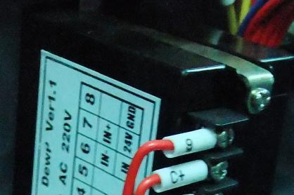
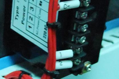
71 Picture 4-17:Connection of Dew-point Monitor 71(78)
72 5. Trouble-shooting Troubles Possible causes Solutions Main power indicator does not light after turn on main power switch. 1. Does not connect through power supply. 2. Main power switch breakdown. 1. Connect through power supply. 2. Replace main power switch. 3. Problems of electrical wires. 3. Check electrical wires. 4. Fuse of control circuit melted. 4. Check electrical wires and replace fuse. 5. Transformer problems. 5. Replace the transformer. E-02 is shown at PV, buzzer sounds and machine stops. Overload alarm of blower lit up, buzzer sounds and machine stops. Pipe heater overheat alarm is lit up, and the buzzer sounds and machine stops working. E-04 is shown at PV, buzzer sounds and machine stops 1. Voltage of power supply is too low. 1. Check the power supply. 2. Phase shortage. 2. Check the power supply. 3. Phase frequency mistakes. 1. Abnormal fluctuation of voltage. 3. Exchange the connection of two of the electrical wires. 1. Check power supply. 2. Blower being stalled. 2. Check the blower. 3. Failures of blower motor. 3. Check the motor. 4. Setting current of overload relay (F1) is too low. 1. Temperature setting mistakes. 4. Set the current of overload relay 1.1 times of rated current of the motor. Reset overload relay: Press down the blue button on the relay after 1 minutes. 1. Correctly set the parameters of temp.controller. 2. Temp. measuring mistakes. 2. Replace thermocouple. 3. Overheat relay of pipe heater failures. 1. Heater contactor seized up. 2. EGO parameter setting wrong. 3. Replace the contactor. 1. Check or replace the heater contactor. 2. Set EGO parameter correctly. 3. EGO fault. 3. Replace EGO. 4. Circuit fault. 4. Check circuit. 72(78)
73 Troubles Possible causes Solutions 1. Problems of rotor motor. 1. Check or replace the motor. E-09 is shown at PV, buzzer sounds and machine stops Abnormal temp. fluctuations. 2. Rotor belt broken. 2. Replace the belt. 3. Problems of electrical circuit. 3. Check the electrical circuit. 4. Micro switch of the rotor failures. 5. Parameter mistakes of timer for control of rotor. 1. Too short of time since start of the machine. 2. Improper parameters for temp. controller. 4. Replace. 5. Reset the timer. (Set time should be bigger than rotor rotating time in one turn and plus 1 minute.) 1. Wait for a while. 2. Check the parameters of temp. Controller. 1. Temp. Setting is too high. 1. Set heater temp. under 180. Heater temp. can not rise up. Breaker tripping off when connects with power supply. 2. Contactor of heater is bad. 2. Replace contactor. 3. Pipe heater is damaged. 3. Replace pipe heater. 4. Problems of thermocouple. 4. Replace thermocouple. 5. Parameter of temp. controller is set to STOP. 6. Temp. controller output problems. 5. Set temp. controller under working mode. 6. Replace or repair temp. controller. 1. Short circuits of main circuit. 1. Check the circuit. 2. Short circuit of transformer. 2. Replace the breaker. 3. Problems of breaker. 3. Replace the breaker. Circuit breaker trips 1. Short circuit of pipe heater. 4. Check the circuit. right after system switch on. 2. Problems of the breaker. 5. Replace the breaker. 73(78)
 Blow off the dust in the rotor channels with compressed air.")
74 6. Maintenance and Repair Honeycomb Rotor cleaning steps: 1) Use a vacuum-cleaner with brush to suck up the dust on rotor surface. 2) Blow off the dust in the rotor channels with compressed air. 3) If there is dirt sticking to the channel walls inside the rotor, cleaning steps are 74(78)
75 as follows: a. Saturate the rotor by blowing humid air (higher than 60%RH) through the rotor without having regeneration circuit on. This can be done by just turning the regeneration heater off and still have the process blower running if process air has high humidity. If the process air is too dry try to put a humidifier in the air stream. Do this for one hour. b. According to the character of the dirt, sink the rotor into water with cleaning agent in it (PH value 3~2 liquid is applied to silica gel, PH value 7~10 applied to molecular valve). Greasy dirt should be put into a detergent solution with xylene. 15 minutes cleaning is suggested. c. Take the rotor out of the liquid and let it rest with the channels vertically for 5 minutes so the liquid can run out. d. Blow off the residual liquid in the channels with compressed air. e. Put the rotor back into the dehumidifier and run the unit with regeneration circuit (the regeneration temperature between 50 and 60 ) on for at least one hour. Note! 1. Note that in the dry air and wet air outlets, there will be high concentrations liquid out for some time. If a solvent has been used, there will be a residual smell for several days. 2. For some dirt which is greasy and sticky in the rotor, 100% elimination is impossible. The only one thing you can do is to replace the rotor for the cleaned rotor performance can only be recovered partly. 6.1 Filter Please periodically clean the dust on the air filters, once per week. Cleaning steps: 1) Take out the air filter carefully. 2) Blow off the dust on the air filter screen and the cover with pressure air. 3) Wipe off the barrel wall of air filter with dishcloth. 4) After cleaning, place all parts in reversed order carefully. 75(78)

 Release the fixed screw on the upper and lower cover of cooler and disassemble the cover.")

76 Picture 6-1:Filter Note! Don't make sundries fall into the barrel, when taking out the air filter The Useful Life of the Key Parts of the Product Table 6-1:The Useful Life of the Key Parts of the Product Name of the parts Blower Process heater Regen. heater Contactor Honeycomb Useful life Above 5 years Above 1 year Above 1 year Above 100,000 act 5~10 years 6.2 Cooler Clear Step 1) Disassemble the cooler's pipe and screw, and remove the cooler out of the chiller. 2) Release the fixed screw on the upper and lower cover of cooler and disassemble the cover. 3) Use brushes, compress ed air or low pressure water to clean the dust and sundries on the cooler fan and copper pipe. Notes: water residue on the cooler fan and copper pipe should be dried with compressed air. 4) Make the cooler's upper and lower cover junction clean enough and smear the silica gel then fixed the covers with screws. 5) Put the cooler on the air at least 4 hours to make the silica gel drying enough then fix the cooler on the chiller and connect all pipes. 76(78)
SCD Series "All-in-One" Compact Dryer
 SCD Series "All-in-One" Compact Dryer Date: Jul. 2014 Version: Ver.D (English) Contents 1. General Description... 9 1.1 Coding Principle... 10 1.2 The main features... 10 1.3 Technical Specifications...
SSM-U Series Storage Mixers
 SSM-U Series Storage Mixers Date: Oct, 2013 Version: Ver.A (English) Contents 1. General Description... 7 1.1 Coding Principle... 8 1.2 Feature... 8 1.3 Technical Specifications... 10 1.3.1 Technical
Portable honeycomb matrix compact dryer, with loading, combines dehumidifying plastic resin and conveying into a single unit.
 Portable honeycomb matrix compact dryer, with loading, combines dehumidifying plastic resin and conveying into a single unit. Comet s CCD series compact honeycomb matrix dryers incorporate drying and dehumidifying
SDL-U-HD Series Heatless Dehumidifying Compact Dryer
 SDL-U-HD Series Heatless Dehumidifying Compact Dryer Date: Nov. 2014 Version: Ver.B (English) Contents 1. General Description... 7 1.1 Coding Principle... 8 1.2 Feature... 8 1.3 Technical Specifications...
SCAD-U Series Compressed Air Dryer
 SCAD-U Series Compressed Air Dryer Date: Jul. 2014 Version: Ver.B (English) Contents 1. General Description... 7 1.1 Coding Principle... 8 1.2 Feature... 8 1.3 Technical Specifications... 11 1.3.1 Specifications...
2.2 Drawing and Parts List
 2.2 Drawing and Parts List 2.2.1 Structural Drawing (SHD-20U~750U) Names of Parts: 1. Main switch 2. Insulated layer 3. Blower 4. Material storage tank 5. Electric heating box 6. Control box 7. Overheat
STM-PW Series High Temp. Water Heater
 STM-PW Series High Temp. Water Heater Date: Apr. 2013 Version: Ver.B (English) Contents 1. General Description... 7 1.1 Coding Principle... 8 1.2 Feature... 8 1.3 Technical Specifications... 10 1.3.1
STM-E ''Standard'' Heater
 STM-E ''Standard'' Heater Date: Apr. 2013 Version: Ver.B (English) Contents 1. General Description... 7 1.1 Coding Principle... 8 1.2 Feature... 8 1.3 Technical Specifications... 10 1.3.1 Specification...
DRYMAX Dryers. Dry Air Dryers for Plastic Resin
 DRYAX Dryers Dry Air Dryers for Plastic Resin DRYAX ES0 Dry Air Dryer The DRYAX ES 0 compact dry air dryers are equipped with one desiccant bed and provide a dry air volume of 0 m /h. Ambient Independent
DDM SERIES. Desiccant Dryer Mobile Drying of free-flowing granular plastic materials
 DDM SERIES Desiccant Dryer Mobile Drying of free-flowing granular plastic materials Desiccant Dryer Mobile - DDM Introduction Labotek s series of mobile desiccant dryers, DDM, is designed for the continuous
DRYING LUXOR E A LUXOR EM A. Compact dryer with integrated conveying
 DRYING Compact dryer with integrated conveying E A EM A DRYING E A / EM A COMPACT DRYER WITH INTEGRATED CONVEYING Both the E A and EM A dryers with optional ETA plus energy saving technology are specifically
Dryers Dry Air Dryers for Plastic Resin. world of innovation
 Dryers Dry Air Dryers for Plastic Resin world of innovation energy rating Energy savings and highest efficiency at the same time After several years of research, WITTANN has developed a standardized rating
Dehumidifying Dryers DP DP 615 Series
 Dehumidifying Dryers DP 604 - DP 615 Series English The DP 604 - DP 615 Dryer Series is suitable for the treatment of hygroscopic polymers for medium productions. The design criteria of these models allows
NovaWheel. Desiccant Wheel Dryer. NovaWheel dryers take a proven drying technology to a new level of excellence reducing your energy costs
 NovaWheel Desiccant Wheel Dryer NW Series: 100-5000 lb./hr.( 36-2272 kg/hr.) NovaWheel dryers take a proven drying technology to a new level of excellence reducing your energy costs D R Y Replace energy-hog
DD200 INDUSTRIAL DEHUMIDIFIER OWNER S MANUAL
 DD200 INDUSTRIAL DEHUMIDIFIER OWNER S MANUAL www.eipl.co.uk Page 1 of 11 UNPACKING Carefully remove the DD200 dehumidifier unit from its transit box and visually check for signs of transit damage. If there
Installation and maintenance instructions for cabin units type vertical IDAC (V50)
") GB Installation and maintenance instructions for cabin units type vertical IDAC (V50). Application. Bundled parts. Handling. Marking. Weight. Transport. Storage 5. Installation 5. Mounting 5. Water trap
GB Installation and maintenance instructions for cabin units type vertical IDAC (V50). Application. Bundled parts. Handling. Marking. Weight. Transport. Storage 5. Installation 5. Mounting 5. Water trap
DRYMAX Dryers. Dry Air Dryers for Plastic Resin. Technology working for you.
 DRYAX Dryers Dry Air Dryers for Plastic Resin Technology working for you. DRYAX P Compressed Air Dryer The drying principle is based on pre-dried, factory supplied compressed air which expands within the
OIL COOLER INSTRUCTION HANDBOOK
 OIL COOLER INSTRUCTION HANDBOOK INDEX 1. GENERALITY 2 1.1 OPERATING RANGE 1.2 IMPORTANT 2. INSTALLATION 3 2.1 TRANSPORTATION 2.2 INSTALLATION LOCATION 2.3 PIPING 2.4 WIRING (see the electrical diagram
DD200 INDUSTRIAL DEHUMIDIFIER OWNER S MANUAL
 DD200 INDUSTRIAL DEHUMIDIFIER OWNER S MANUAL www.eipl.co.uk Page 1 of 15 DD200 PACKAGE CONTENTS Item Description Quantity 10502SS-US Dehumidifier 1 3033807 Free plug 1 TPC356 Manual 1 Page 2 of 15 UNPACKING
OPERATING MANUAL Gfp 255C Please read this manual carefully before operating!
 OPERATING MANUAL Gfp 255C Please read this manual carefully before operating! Unpacking, assembly, and operating videos are available at www.gfpsmoothstart.com 1 Table of Contents Gfp 255C March 2015 Contents
Chiltrix 5.1 Thin DC - Inverter Water Fan Coil Unit Floor, Wall or Ceiling Universal Mount Manual
 Chiltrix 5.1 Thin DC - Inverter Water Fan Coil Unit Floor, Wall or Ceiling Universal Mount Manual Version 1.5 1 CONTENTS CHAPTER 1 GENERAL INTRODUCTION...3 1. Preface... 3 2. Product Introduction... 3
INTERNATIONAL MACHIINE CONCEPTS. Operating Manual. Tablet Counting and Filling Machine. Model IMC
 Operating Manual Tablet Counting and Filling Machine Model IMC-16-1 - CONTENTS 1. Precautions 2. Introduction to the machine 3. Relevant Technical Data 4. Working environment 5. Introduction to the control
MicroWheel. MW1 Model USER GUIDE UGD
 USER GUIDE UGD052-0914 www.conairgroup.com MicroWheel MW1 Model Corporate Office: 724.584.5500 Instant Access 24/7 (Parts and Service): 800.458.1960 Parts and Service: 814.437.6861 Please record your equipment
HTD. High Temperature Non-Cycling Refrigerated Compressed Air Dryers. Operation & Maintenance Manual. MODELS HTD 21 thru HTD 100
 HTD High Temperature Non-Cycling Refrigerated Compressed Air Dryers Operation & Maintenance Manual MODELS HTD 21 thru HTD 100 - TABLE OF CONTENTS - 1.0 GENERAL 2 1.1 How to use this manual 1.2 Symbols
Warning: 230V / 1ph / 50Hz V / 3ph / 50Hz. Remarks: Make sure that you have enough power. (See page 15 Cable table)
") 1 2 Warning: - Do not place your hand or any other objects into the air outlet and fan. It could damage the heat pump and cause injuries; - In case of any abnormality with the heat pump, cut off the power
1 2 Warning: - Do not place your hand or any other objects into the air outlet and fan. It could damage the heat pump and cause injuries; - In case of any abnormality with the heat pump, cut off the power
RC-54CA RO-50CA RC-54HA RO-50HA. SPLIT TYPE AIR CONDITIONER CASSETTE TYPE (50Hz) Indoor unit Outdoor unit
 Indoor unit Outdoor unit") SPLIT TYPE AIR CONDITIONER CASSETTE TYPE (50Hz) Indoor unit Outdoor unit RCW-54CB RO-50CA RC-54CA RO-50CA RC-54HA RO-50HA CONTENTS SPECIFICATIONS OUTLINE AND DIMENTIONS CIRCUIT DIAGRAM REFRIGERANT SYSTEM
SPLIT TYPE AIR CONDITIONER CASSETTE TYPE (50Hz) Indoor unit Outdoor unit RCW-54CB RO-50CA RC-54CA RO-50CA RC-54HA RO-50HA CONTENTS SPECIFICATIONS OUTLINE AND DIMENTIONS CIRCUIT DIAGRAM REFRIGERANT SYSTEM
POD Silo Dehumidifier Series. with Logo! TM PLC POD-150 DOCUMENT: POD IM 14 DEC NOVATEC, Inc All Rights Reserved
 POD Silo Dehumidifier Series with Logo! TM PLC POD-150 NOVATEC, Inc. 2016 All Rights Reserved DOCUMENT: 2012 Novatec, Inc. All Rights Reserved Page 2 VL-VLP IM 10-24-2012 NOTES: Please record the following
UNDERCOUNTER LABORATORY REFRIGERATORS and FREEZERS Installation, Operation and Maintenance Instructions
 UNDERCOUNTER LABORATORY REFRIGERATORS and FREEZERS Installation, Operation and Maintenance Instructions INSPECTION When the equipment is received, all items should be carefully checked against the bill
SERVICE MANUAL MULTI DECK 60 HOT MERCHANDISER MULTI DECK 100 HOT MERCHANDISER MULTI DECK 120 HOT MERCHANDISER CLASSIC DECK HOT MERCHANDISER
 SERVICE MANUAL MULTI DECK 60 HOT MERCHANDISER MULTI DECK 100 HOT MERCHANDISER MULTI DECK 120 HOT MERCHANDISER CLASSIC DECK HOT MERCHANDISER Classic Deck Hot Multi Deck 60 Multi Deck 100 Multi Deck 120
Remote Vacuum Sensor and Variable Speed Vacuum Pump Control Manual. Version Date - June Part Number
 Innovation In and Out of Parlour Remote Vacuum Sensor and Variable Speed Vacuum Pump Control Manual Version - 1.0 Date - June 2016 Part Number - 39-0038 Index Manual Version... 3 About the Remote Vacuum
Dehumidifying Dryers DP DP 615 Series
 Dehumidifying Dryers DP 604 - DP 615 Series English The DP 604 - DP 615 Dryer Series is suitable for the treatment of hygroscopic polymers for medium productions. The design criteria of these models allow
INSTRUCTIONS FOR THD-U SERIES HOT AIR MATERIAL DRYERS
 INSTRUCTIONS FOR THD-U SERIES HOT AIR MATERIAL DRYERS Copyright Plastic Process Equipment, Inc 2015 Our PPE Material Dryers are a PPE exclusive only available from PPE. Do not confuse these with any other
Customers. The core of our innovation. Feeding&Conveying. Drying Dosing Temperature Control Refrigeration Granulation
 EN Customers. The core of our innovation Feeding&Conveying Drying Dosing Temperature Control Refrigeration Granulation Piovan Drying Technologies: Desiccant Bed Dryers Dried air is generated by means of
INSTRUCTIONS FOR USE OF COMBINED BOILER INTENDED FOR COMBUSTION OF BOTH PELLETS AND SOLID FUEL ABC COMBO
 INSTRUCTIONS FOR USE OF COMBINED BOILER INTENDED FOR COMBUSTION OF BOTH PELLETS AND SOLID FUEL ABC COMBO .Technical specifications Boiler power DESCRIPTION Water content in a boiler Required draft Supply
Bench-Top Vacuum Oven with 28 segments programmable controller
 Bench-Top Vacuum Oven with 28 segments programmable controller DZF-6000F Series Vacuum Oven MTI Corporation www.mtixtl.com 1 Safety notes DZF Vacuum Oven Please read the following safety notes carefully
Drying your polymer. Why? Surface Moisture Hygroscopic: Hygroscopic: tending to absorb moisture from the air W I T H DRYING TECHNOLOGIES
 Drying your polymer Why? Surface Moisture Hygroscopic: Hygroscopic: tending to absorb moisture from the air W I T H DRYING TECHNOLOGIES Drying your polymer And Because all material manufacturers recommend
EQUIPMENT PRE-STARTUP AND STARTUP CHECKLIST TEL NO: ORDER NO: CONTRACT NO:
 Supersedes: (316) Form QTC4-CL2 (617) MODEL QTC4 EQUIPMENT PRE-STARTUP AND STARTUP CHECKLIST CUSTOMER: ADDRESS: PHONE: JOB NAME: LOCATION: CUSTOMER ORDER NO: TEL NO: ORDER NO: CONTRACT NO: CHILLER MODEL
EVAPORATIVE AIR COOLER SERVICE MANUAL
 EVAPORATIVE AIR COOLER SERVICE MANUAL CAUTION: Before servicing the unit, read the Safety Precautions in this manual. Only for authorized service. MODEL NO.: CL30XC & CHL30XC (INDOOR USE ONLY) CONTENT
BGA Rework Station TOUCHBGA GM490 User Manual
 BGA Rework Station TOUCHBGA GM490 User Manual touchbga.com 1. BGA Rework Station Setting Up 2. BGA Rework Station Safety Precautions 3. BGA Rework Station Main Specification 4. BGA Rework Station Operation
NDB Dryers with NovaTouch PLC Control
 NDB Dryers with NovaTouch PLC Control NOVATEC, Inc. 2016 All Rights Reserved DOCUMENT: NDB_NovaTouch PLC IM 19 JAN 2012 NOVATEC, Inc. All Rights Reserved Page 2 VL-VLP IM 10-24-2012 NOTES: Please record
VT600. Operation & Parts Manual. XtraVac VT600 (PLC) Vacuum Tumbler
 Vacuum Tumbler") VT600 XtraVac VT600 (PLC) Vacuum Tumbler Operation & Parts Manual A Division of the Inauen Group Kansas City, MO USA Tel. 800-728-2999 Fax 816-472-1999 Sales@XtraVac.com Safe Operation Practices General
VT600 XtraVac VT600 (PLC) Vacuum Tumbler Operation & Parts Manual A Division of the Inauen Group Kansas City, MO USA Tel. 800-728-2999 Fax 816-472-1999 Sales@XtraVac.com Safe Operation Practices General
MODEL YVAA EQUIPMENT PRE-STARTUP AND STARTUP CHECKLIST CUSTOMER: LOCATION: ADDRESS: CUSTOMER ORDER NO: PHONE: JCI CONTRACT NO: JOB NAME:
 Supersedes: 201.28-CL2 (817) Form 201.28-CL2 (1017) MODEL YVAA EQUIPMENT PRE-STARTUP AND STARTUP CHECKLIST CUSTOMER: LOCATION: ADDRESS: PHONE: JOB NAME: CUSTOMER ORDER NO: JCI CONTRACT NO: CHILLER MODEL
FDT11 FDT15 FDT18. DUCTED TYPE SPLIT SYSTEMS (3 Phase, Fixed Speed)
") OPERA TION & I NSTALLAT I O N FDT11 FDT15 FDT18 MANUAL DUCTED TYPE SPLIT SYSTEMS (3 Phase, Fixed Speed) Read this operating & installation instruction carefully and keep it for future reference DUCTED
OPERA TION & I NSTALLAT I O N FDT11 FDT15 FDT18 MANUAL DUCTED TYPE SPLIT SYSTEMS (3 Phase, Fixed Speed) Read this operating & installation instruction carefully and keep it for future reference DUCTED
THROUGH-WALL AIR-TO-AIR HEAT PUMP AND AIR CONDITIONER. Instruction Manual. Model AMB-12H
 THROUGH-WALL AIR-TO-AIR HEAT PUMP AND AIR CONDITIONER Instruction Manual Model AMB-12H PLEASE READ THIS INSTRUCTION MANUAL CAREFULLY BEFORE USING THIS UNIT. Table of Contents 1. SAFETY WARNINGS 2 2. CONSTRUCTION...
MDX. Non-Cycling Refrigerated Compressed Air Dryers with Intellidrain Condensate Drain Trap. Operation & Maintenance Manual
 MDX Non-Cycling Refrigerated Compressed Air Dryers with Intellidrain Condensate Drain Trap Operation & Maintenance Manual MODELS MDX 1500 1800 2400 3000 TABLE OF CONTENTS 1.0 GENERAL 2 1.1 How to use this
FHHT 18 3 PHASE /32A / 400V ELECTRIC HEATER PRODUCT MANUAL P
 FHHT 18 3 PHASE /32A / 400V ELECTRIC HEATER PRODUCT MANUAL P 1 of 13 These instructions should be read by: The specifying engineer. The installation engineer. The user. The service engineer. WARNINGS Failure
! WARNING To avoid risk of electrical shock, personal injury or death; disconnect power before servicing, unless testing requires power.
 27 Electric Dryer Technical Information MDE9700A * Due to possibility of personal injury or property damage, always contact an authorized technician for servicing or repair of this unit. Refer to Service
INSTRUCTION MANUAL. Laboratory Equipment Pty Ltd Ph: Fax:
 INSTRUCTION MANUAL Laboratory Equipment Pty Ltd email: sales@labec.com.au Ph: 02 9560 2811 Fax: 02 9560 6131 www.labec.com.au 2014 Shaking Water Bath Instruction Manual Model : J-SWB19, J-SWB35, J-SWB60
! WARNING To avoid risk of electrical shock, personal injury or death; disconnect power before servicing, unless testing requires power.
 27 Gas Dryer Technical Information MDG9700A * Due to possibility of personal injury or property damage, always contact an authorized technician for servicing or repair of this unit. Refer to Service Manual
SELF-PRIMING JET PUMPS
 SS Anti-Rust SS Shaft Copper & Cold-rolled SELF-PRIMING JET PUMPS CONTENTS 1. Applications.... Model Description.... Technical Data... 4. Implementation Standards... 5. Safety Precautions... 6. Product
D Carousel Dryer - DC-1
 www.conairnet.com USER GUIDE UGD024/0304 D Carousel Dryer - DC-1 Models 15, 25, 50, 75, and 100 with DC-1 Controls INTRODUCTION Purpose of the User Guide How the guide is organized Your responsibilities
All series is using Hitachi scroll compressor, low vibration and high efficiency. Internal thermostat embedded compressors, and it can react quickly.
 HITACHI proudly presents to our customers this wide range of split system air conditioners, from 4HP to 20 HP which is designed for high and medium outdoor temperature and comply with almost any types
Carousel Plus Dryer. W Series Models 15, 25, 50, 75 and 100 with DC-1 Controls
 USER GUIDE UGD032-0407 www.conairnet.com Carousel Plus Dryer W Series Models 15, 25, 50, 75 and 100 with DC-1 Controls INTRODUCTION Purpose of the User Guide How the guide is organized Using the Carousel
HB CDA SERIES WITH TEMPERATURE SETBACK
 HB CDA SERIES WITH TEMPERATURE SETBACK 2013 NOVATEC, Inc. All Rights Reserved Document: HB CDA IM 7-24-2013 NOTES: Please record the following information, which is specific to this piece of equipment,
KQ Series. Multistage Booster Pump System. Installation Manual. ISO 9001 Certified KQ200/400 KQ800
 KQ Series Multistage Booster Pump System Installation Manual KQ200/400 KQ800 ISO 9001 Certified Description The KQ series booster pump is an all-in-one compact and reliable automatic multistage centrifugal
DRI-AIR INDUSTRIES, INC. ARID-X10C FLOOR MOUNT DRYER OPERATING MANUAL
 ARID-X10C FLOOR MOUNT DRYER OPERATING MANUAL Page 1 DRI-AIR INDUSTRIES, INC. 16 THOMPSON ROAD P.O. BOX 1020 EAST WINDSOR, CT 06088-1020 Tel. (860) 627-5110 FAX (860) 623-4477 Internet http://www.dri-air.com
OPERATION MANUAL KP4041 POLY SCRAP COMPACTOR
 OPERATION MANUAL KP4041 POLY SCRAP COMPACTOR IBIS INTERNATIONAL Thank you for purchasing the KP4041 Poly Scrap Compactor. IBIS appreciates your confidence in our product, and promises to support its operation
Installation and Operation Manual Package Air Conditioners
 Installation and Operation Manual Package Air Conditioners Please read this manual carefully before using this product and keep it properly for future reference. Contents 1.Pre-Installation Instruction...
Engineers manual. Under counter machines
 Table of Contents 1. INTRODUCTION... 3 1.1 1.2 1.3 INSTALLATION AND COMMISSIONING... 3 SERVICE AND REPAIRS... 3 MODIFICATION... 3 2. EXPLANATION OF SYMBOLS USED... 3 3. WARNING AND SAFETY INFORMATION...
Model No: Little Devil II (inc ss)
") GAS HEATER Model No: Little Devil II (inc ss) PART NO: 6926020, 6926025 (SS) OPERATION & MAINTENANCE INSTRUCTIONS LS1213 INTRODUCTION Thank you for purchasing this CLARKE Gas Heater. Before attempting
GAS HEATER Model No: Little Devil II (inc ss) PART NO: 6926020, 6926025 (SS) OPERATION & MAINTENANCE INSTRUCTIONS LS1213 INTRODUCTION Thank you for purchasing this CLARKE Gas Heater. Before attempting
EAGLE 2000B EAGLE 2000BE EAGLE 2000EBT MUST READ MANUAL PRIOR TO INSTALLING MACHINE
 EAGLE 2000B EAGLE 2000BE EAGLE 2000EBT MUST READ MANUAL PRIOR TO INSTALLING MACHINE Contents 1 Machine Safety Information 3 1.5 Safety Precautions Prior to Operating Machine 6 2 Machine Installation 7
40LM Hz INSTALLATION, START-UP AND SERVICE INSTRUCTIONS CHILLED WATER FAN COIL UNIT
 Carrier International Sdn. Bhd. Malaysia INSTALLATION, START-UP AND SERVICE INSTRUCTIONS CHILLED WATER FAN COIL UNIT 40LM 120-200 50Hz CONTENTS: Physical Data & Dimension 1-3 Safety Considerations 4 Rigging
INSTRUCTIONS FOR TAL SERIES VACUUM HOPPER LOADER
 INSTRUCTIONS FOR TAL SERIES VACUUM HOR LOADER TAL-15U 150 LBS PER HOUR MAGNETIC LEVEL SWITCH TAL-3U-E 450 LBS PER HOUR SIGHT GLASS WITH PROXIMITY LEVEL SWITCH Proportional Dual Feed Valve Available TAL-6U
G-10s. Instruction Manual. G-Series Cooler UPRIGHT COOLER. Part No.11IPA
 G-Series Cooler UPRIGHT COOLER Part No.11IPA-062800 Instruction Manual FOR YOUR FUTURE REFERENCE Thank you for using our product. This manual will guide you in getting the best use of your cooler. Remember
POLAR TEMP FARM MORTALITY UNIT OPERATION MANUAL
 POLAR TEMP FARM MORTALITY UNIT OPERATION MANUAL www.polartemp.com TABLE OF CONTENT Disclaimer.......................................... Page 3 Inspection, unpacking and FMU setup.................. Page
Manual DFD Desiccant Flex Dryer Lab-Dry
 Manual DFD Desiccant Flex Dryer Lab-Dry Serial No... ISO 08.01.02.058.GB LT no.: 986497 Rev. N00 Date: 2016.12.16 SIEMENS asdasdasdasd asdasdasdasd ON SIMAT EK PANEL OFF Rev. N00 DFD Desiccant Flex Dryer,
Operation Manual R205BV, R209BV
 Operation Manual R205BV, R209BV 1 Safety Instruction The rotary evaporator is manufactured according to current methods and accepted safety regulations. However, risks still exist during the installation,
Wired Remote Controller XK19 and Wireless Remote Controller YT1F
 and Wireless Remote Controller YT1F Owner's Manual Commercial Air Conditioners Thank you for choosing Commercial Air Conditioners, please read this owner s manual carefully before operation and retain
! WARNING To avoid risk of electrical shock, personal injury or death; disconnect power to dryer before servicing, unless testing requires power.
 27 Domestic Dryer Technical Information MDE6700A*, MDG6700A* Due to possibility of personal injury or property damage, always contact an authorized technician for servicing or repair of this unit. Refer
PGD930DES USER MANUAL. VER
 PGD930DES USER MANUAL www.pridiom.com VER. 1-261112 THANK YOU Thank you for choosing this innovative Pridiom dehumidifier. This instruction manual describes the many benefits and advanced features that
DRI-AIR INDUSTRIES, INC. HA750B B HOT AIR DRYER OPERATING MANUAL
 HA750B - 1500B HOT AIR DRYER OPERATING MANUAL Page 1 DRI-AIR INDUSTRIES, INC. 16 THOMPSON ROAD P.O. BOX 1020 EAST WINDSOR, CT 06088-1020 Tel. (860) 627-5110 FAX (860) 623-4477 Internet http://www.dri-air.com
3HP MOBILE CYCLONE DUST COLLECTOR MANUAL FILTER CLEANING MANUAL
 3HP MOBILE CYCLONE DUST COLLECTOR MANUAL FILTER CLEANING MANUAL LAGUNA TOOLS 2072 Alton Parkway Irvine, California 92606 Ph: 800.234.1976 www.lagunatools.com 2018, Laguna Tools, Inc. LAGUNA and the LAGUNA
COMMERCIAL REFRIGERATOR & FREEZER SERVICE MANUAL (SCL/SCLM)
") COMMERCIAL REFRIGERATOR & FREEZER SERVICE MANUAL (SCL/SCLM) MODEL: SCL1 SCL2 SCL2-36 SCL2-60 SCL3 SCLM1 SCLM2 SCLM2-36 SCLM2-60 SCLM3 TABLE OF CONTENTS 1. EXPLODED VIEW AND PARTS LIST... 3 1.1 SCL1 & SCLM1...
COMMERCIAL REFRIGERATOR & FREEZER SERVICE MANUAL (SCL/SCLM) MODEL: SCL1 SCL2 SCL2-36 SCL2-60 SCL3 SCLM1 SCLM2 SCLM2-36 SCLM2-60 SCLM3 TABLE OF CONTENTS 1. EXPLODED VIEW AND PARTS LIST... 3 1.1 SCL1 & SCLM1...
E U R O V E N T CERTIFIED PERFORMANCE
 Compact Horizontal Air-Air Heat Pump Model RTH-7K to 3K Ref.: Y-R719 7 Technical information E U R O V E N T CERTIFIED PERFORMANCE I S O 9 1 ER-8/1991 Clima Roca York S.L. is participating in the EUROVENT
XtraVac VT3000 Vacuum Tumbler. Operation & Parts Manual
 VT3000 XtraVac VT3000 Vacuum Tumbler Operation & Parts Manual A Division of the Inauen Group Kansas City, MO USA Tel. 800-728-2999 Fax 816-472-1999 Sales@XtraVac.com Safe Operation Practices General Operation.Read,
NWB NovaWheel Dryers NWB and NWB+ Dryers Series
 Portable Dryer with 4 or 7 color touch screen PLC Throughput: 25-400 lb/hr (11-182 Kg/hr) NWB NovaWheel Dryers NWB and NWB+ Dryers Series NWB+ Series include a 7 color touch screen PLC control with unique
Engineers manual. Pass Through machines P500 P500 A P500 AS P500 A WS P500 AS WS. A- AirBreak WS Water Softener. AS Dual Rinse Element
 P500 P500 A P500 AS P500 A WS P500 AS WS A- AirBreak WS Water Softener AS Dual Rinse Element Table of Contents 1. INTRODUCTION... 3 1.1 1.2 1.3 INSTALLATION AND COMMISSIONING... 3 SERVICE AND REPAIRS...
Application Manual Loop Water Controller
 Application Manual Loop Water Controller AM - LWC TABLE OF CONTENTS LIST OF FIGURES ii iii 1.0 SAFETY CONSIDERATION 1 1.1 Installation Recommendations 1 2.0 GENERAL DESCRIPTION 2 2.1 General Introduction
User s Manual WS-4830SS WS-4836SS NOTE: PLEASE INSPECT HOOD IMMEDIATELY UPON RECEIVING. CLAIM OF DAMAGE AFTER 7 DAYS OF DELIVERY WILL BE DENIED.
 www.windsterhood.com User s Manual UNDER CABINET SERIES WS-4830SS WS-4836SS NOTE: PLEASE INSPECT HOOD IMMEDIATELY UPON RECEIVING. CLAIM OF DAMAGE AFTER 7 DAYS OF DELIVERY WILL BE DENIED. This unit is designed
INSTALLATION MANUAL. Decoration Panel Provided with Filter Auto Cleaning Function Self Cleaning decoration panel BYCQ140D7GW1 BYCQ140D7GFW1
 INSTALLATION MANUAL Decoration Provided with Filter Auto Cleaning Function Self Cleaning decoration panel BYCQ0D7GW BYCQ0D7GFW BYCQ0D7GW BYCQ0D7GFW Installation manual Contents. SAFETY PRECAUTIONS....
Quick Start Guide. 4MP Vandal Dome Fixed Lens IP Camera O4D1
 Quick Start Guide 4MP Vandal Dome Fixed Lens IP Camera O4D1 Version 1.1.1 Welcome Thank you for purchasing this Network camera! This manual is designed to be a reference tool for your system. Please read
Temptek Auxiliary Equipment
 Temptek Auxiliary Equipment Mold Temperature Controllers - Water Units VT-275-LX VT Series Mold Temperature Controllers are used to process temperature control to 250 F. These units use an incoloy heater
OWNER S MANUAL ABSFBM-200T
 OWNER S MANUAL ABSFBM-200T American Baking Systems, Inc 290 Legion Court S.W. Cedar Rapids, IA 52404 Phone: 319-373-5006 Fax: 319-373-5008 CONTENTS Introduction (2) Installation & Commissioning (3) Operation
Carousel Plus Dryer. W Series Models 150, 200, 300 and 400 with DC-A Control USER GUIDE UGD
 USER GUIDE UGD058-0317 www.conairgroup.com Carousel Plus Dryer W Series Models 150, 200, 300 and 400 with DC-A Control Corporate Office: 724.584.5500 l Instant Access 24/7 (Parts and Service): 800.458.1960
T-Series Air Conditioner T20 Model
 INSTRUCTION MANUAL T-Series Air Conditioner T20 Model Protecting Electronics. Exceeding Expectations. McLean Cooling Technology 11611 Business Park Blvd N Champlin, MN 55316 USA Tel 763-323-8200 Fax 763-576-3200
Operation Manual. (Version 1.5.1)
") VWR symphony TM Gravity Convection General Incubator Operation Manual (Version 1.5.1) VWR symphony Gravity Convection General Incubator 414004-610, 414004-612, 414004-614, 414004-616 414004-611, 414004-613,
VWR symphony TM Gravity Convection General Incubator Operation Manual (Version 1.5.1) VWR symphony Gravity Convection General Incubator 414004-610, 414004-612, 414004-614, 414004-616 414004-611, 414004-613,
T-SERIES Air Conditioner. T43 Model INSTRUCTION MANUAL nvent Rev. I P/N
 T-SERIES Air Conditioner T43 Model INSTRUCTION MANUAL Rev. I P/N 10-1008-145 TABLE OF CONTENTS Warranty and Return Policy...2 IMPORTANT NOTICE...2 RECEIVING THE AIR CONDITIONER...3 HANDLING AND TESTING
Magnetic Stirring Systems with Heat
 Sharing your passion for making jewelry. Products. Service. Know-how. Magnetic Stirring Systems with Heat 335-212 Digital Ceramic Magnetic Stirring System with Heated Stand 335-211 Ceramic Magnetic Stirring
User s Information Manual
 48N2,N3,N4,N5,N6,N7,N8,N9 75-150 Ton Gas Heating/Electric Cooling Units with ComfortLink Controls User s Information Manual NOTE TO INSTALLER: This manual should be left with the equipment owner. : If
OPERATING & SERVICE PARTS MANUAL HDS-215 COMBINATION SHRINK SYSTEM
 OPERATING & SERVICE PARTS MANUAL HDS-215 COMBINATION SHRINK SYSTEM FOR HOT KNIFE AND IMPULSE MACHINES READ ALL INSTRUCTIONS CAREFULLY BEFORE OPERATING EQUIPMENT TABLE OF CONTENTS Electrical Requirements
INSTALLATION OPERATION & MAINTENANCE INSTRUCTION HEAT RECOVERY UNITS VHR MODELS
 INSTALLATION OPERATION & MAINTENANCE INSTRUCTION HEAT RECOVERY UNITS VHR MODELS TSEK VENCO Havalandırma ve Makina San.ve Tic. A.Ş. 2004. Cad. No:5 45400 OSB Turgutlu MANISA / TURKİYE Tel: +90 (236) 332
B. Unit construction shall comply with ASHRAE 15 Safety Code, NEC, and ASME applicable codes (U.S.A. codes).
.") Guide Specifications PART 1 GENERAL 1.01 SYSTEM DESCRIPTION Microprocessor controlled, air-cooled liquid chiller utilizing scroll compressors, low sound fans, hydronic pump system and optional fluid storage
Guide Specifications PART 1 GENERAL 1.01 SYSTEM DESCRIPTION Microprocessor controlled, air-cooled liquid chiller utilizing scroll compressors, low sound fans, hydronic pump system and optional fluid storage
USER S MANUAL. VCU/VCUN Series CENTRIFUGAL FAN IN SCROLL CASING
 USER S MANUAL VCU/ Series CENTRIFUGAL FAN IN SCROLL CASING 2 CONTENTS Introduction Use Delivery set Designation key Technical data Safety requirements Design and operating logic Mounting and set-up Connection
Customized Industrial Products
 Customized Industrial Products Product Catalog Large Walk-in Type Drying Oven Large Size Autoclave Large Size Fine Oven Targeting Productivity Improvement Yamato offers customization of products based
Products documentation (REVISION DATE: 03/10/2011) OMFP6010 (60cm PIROLITIC OVEN)
 OMFP6010 (60cm PIROLITIC OVEN)") Products documentation (REVISION DATE: 03/10/2011) OMFP6010 (60cm PIROLITIC OVEN) Ovens Service Manual Models OMFP6010 CONTENTS This document has been published to be used for service only. The contents
Products documentation (REVISION DATE: 03/10/2011) OMFP6010 (60cm PIROLITIC OVEN) Ovens Service Manual Models OMFP6010 CONTENTS This document has been published to be used for service only. The contents
Part 3 Troubleshooting
 Part Troubleshooting What is in this part? This part contains the following chapters: Chapter See page Troubleshooting 2 Error Codes: Hydro-box 7 Error Codes: Outdoor Units Error Codes: System Malfunctions
Dehumidifier User Manual. (For the series of DP40~DP70)
") Dehumidifier User Manual (For the series of DP40~DP70) Content I. Please read immediately... 1 II. Application... 2 III. Features... 2 IV. Technical Parameters... 3 V. Overall Dimension... 4 VI. Installation
Dehumidifier User Manual (For the series of DP40~DP70) Content I. Please read immediately... 1 II. Application... 2 III. Features... 2 IV. Technical Parameters... 3 V. Overall Dimension... 4 VI. Installation
TECHNICAL SERVICE MANUAL SCALA - SC
 TECHNICAL SERVICE MANUAL SCALA - SC MODELS: SCALA 400 - SC 400 SCALA 600 - SC 600 SCALA 1T - SC 1TN SCALA 2T - SC 2TN SCALA 3T - SC 3TN SCALA 5T - SC 5TN SCALA 10T - SC 10TN SCALA 15T - SC 15TN TABLE OF
Instruction Manual. Portable Air Conditioner
 Instruction Manual Portable Air Conditioner Model: WA-9010E It is important that you read these instructions before using your portable air conditioner and we strongly recommend that you keep them in a
T-Series Air Conditioner T15 Model
 INSTRUCTION MANUAL T-Series Air Conditioner T15 Model Protecting Electronics. Exceeding Expectations. McLean Cooling Technology 11611 Business Park Blvd N Champlin, MN 55316 USA Tel 763-323-8200 Fax 763-576-3200