OmniLogic. Automation and Chlorination. Installation Manual. Contents HLBASEAU
|
|
|
- Jerome Davidson
- 5 years ago
- Views:
Transcription
 Pty, Ltd. Melbourne, Sydney, Brisbane, Perth www.")
1 RevA OmniLogic Automation and Chlorination Installation Manual Contents Before You Begin...1 Overview...1 Mounting Equipment...4 Plumbing...6 Wiring...10 Preparing Pool/Spa Water...21 System Startup...23 Configuration Wizard...24 HLBASEAU Hayward Pool Products (Australia) Pty, Ltd. Melbourne, Sydney, Brisbane, Perth
2 IMPORTANT SAFETY INSTRUCTIONS When using this electrical equipment, basic safety precautions should always be followed, including the following: READ AND FOLLOW ALL INSTRUCTIONS WARNING: RISK OF ELECTRIC SHOCK. The means of disconnection must be incorporated in the fixed wiring supplying the unit with all supply circuits being supplied through an RCD with a 30mA residual operating current. The unit must be mounted outside of the swimming pool zones or further than 3.5 metres from the edge of the water on a solid structure and all electrical wiring must be performed by a qualified and licensed electrical contractor in accordance with all local electrical regulations and the latest edition of AS/NZS3000 Wiring Rules. WARNING: Water in excess of 40 degrees Celsius may be hazardous to your health. WARNING: This appliance can be used by children aged from 8 years and above and persons with reduced physical, sensory or mental capabilities or lack of experience and knowledge if they have been given supervision or instruction concerning use of the appliance in a safe way and understand the hazards involved. WARNING: Do not use the OmniLogic to control fire pits or related fire equipment. A green colored terminal marked Earth is located inside the wiring compartment. To reduce the risk of electric shock, this terminal must be connected to the earth bar located in the main switchboard or distribution board where the electrical feed is coming from with a continuous copper wire as defined in accordance with all local electrical regulations and AS/NZS 3000 Wiring Rules latest edition. If the pool shell, deck, conductive fixtures and fittings, and equipment need to be equipotential bonded as per the requirements of AS/NZS 3000 Wiring Rules latest edition, then the OmniLogic has an equipotential bonding lug located on the base of the unit. A copper conductor with a cross-sectional area not less than 4mm2 shall be used to connect all items to the equipotential bonding conductor common connection point. WARNING: Disconnect/Isolate all power feeds to the unit before servicing or installing/retrieving USB Thumb Drive. Other than fuses, there are no user serviceable parts inside the controller. WARNING: Always read and become familiar with Material Safety Data Sheets (MSDS) and safe handling instructions for all chemicals used with the OmniLogic and the pool/spa in general. Cleaning and user maintenance shall not be made by children with out competent adult supervision. WARNING: Always take and record manual water chemistry readings in conformance with local and national Health Department requirements. Although automated controllers are a great aid in maintaining healthy water quality, controllers are not a substitute for manual water testing with an accurate test-kit. SAVE THESE INSTRUCTIONS
3 Table of Contents Introduction Preparing Mounting Equipment Plumbing Electrical Wiring Pool/Spa Water Installation Steps...3 OmniLogic Enclosure...4 Temperature Sensors...5 Optional Chlorination...5 Optional HLCHEMAU Sensing Kit...5 Optional 1F-CHEMPUMPPS ph Dispensing...5 Optional HLWALLMOUNT...5 Optional HLWLANAU...5 Optional Valve Actuators...6 Pool/Spa Configuration...6 TurboCell...9 Flow Switch...9 Wiring Overview...10 Main Service...11 Earthing and Equipotential Bonding...11 Circuit Breaker Installation and Wiring...11 OmniLogic Power...11 Pool Equipment Connection Table...12 High Voltage Pool Equipment...13 Low Voltage Wiring...14 General Water Chemistry...21 Salt...22 Final Steps Startup and Configuration Warranty System Startup...23 Startup and Configuration Wizard...24 Bodies of Water...25 Filter Pumps...26 Heaters...27 HLCHEMAU...28 Chlorinator...29 Cleaners...29 Water Features...30 ColorLogic Lights...31 Other Lights...31 Accessories...32 Shared Equipment...33 Sensors...33 Backyard Accessories...34 Interlocks...34 Quick Edit...37 OmniLogic Limited Warranty...43
4 Before you Begin What s Included Before attempting to install the OmniLogic system, check that the following components have been included in the package: OmniLogic Electronics Unit (3) Temperature sensors with 4.5m cable, hose clamp Ferrite bead for ethernet cable Spare main board fuses What s NOT Included Some of the additional items that you may need to complete an installation include: Circuit breakers Circuit Breaker and 30mA RCD for maximum combined load supply circuit of 63A. Wire 4-conductor cable for connection to optional wired terminal(s) 63A total maximum combined load from main switchboard or sub board to OmniLogic Wire/conduit or GPO s for installation of additionally switched/controlled power outlets Wire for remote heater control and other low voltage devices Wire for equipotential bonding Miscellaneous Mounting hardware (screws, bolts, etc.) for mounting OmniLogic and remote terminals Valve Actuators (to automate valve functions) Accessory Products - Order Separately HLIOEXPAND HLWLANAU HLWALLMOUNT HL-CHEMAU 1F-CHEMPUMPPS GVA-24 V&A-xx T-CELL-3 T-CELL-9 T-CELL-15 P-KIT Input/Output Expander Board adds 4 additional sensor/external inputs, 4 heater/low voltage outputs, and 4 actuator outputs Wireless home network connectivity - eliminates the need to hard wire the OmniLogic to the home s router/access point Wired Wall Mount Remote Terminal ORP & ph Sensing Kit for monitoring and controlling pool chemistry Hayward Chemical Pump used for acid dispensing to reduce ph Valve Actuator Valve & Actuator - xx=1p (40mm/1.5 pos. seal), 2P (50mm/2 pos. seal) Chlorinator Cell - generates chlorine for pools up to 55k litres Chlorinator Cell - generates chlorine for pools up to 95k litres Chlorinator Cell - generates chlorine for pools up to 150k litres Chlorination plumbing kit containing flow switch and cell unions NOTE: Before installing this product as part of a saline water purification system in a pool or spa using natural stone for coping or for immediately adjacent patios/decking, a qualified stone installation specialist should be consulted regarding the appropriate type, installation, sealant (if any) and maintenance of stone used around a saline pool with an electronic chlorine generator in your particular location and circumstances. NOTE: The use of dry acid (sodium bisulfate) to adjust pool ph is discouraged especially in arid regions where pool water is subject to excessive evaporation and is not commonly diluted with fresh water. Dry acid can cause a buildup of by-products that can damage your chlorinator cell. Overview The OmniLogic HLBASEAU is a multifunction pool automation control that is expandable to meet all your needs and fully manage your pool/spa system. The OmniLogic can control pumps, valves, lighting, heaters, pool chemistry and more. It offers the next generation of technology to manage pool/spa equipment and the backyard experience. Using a touchscreen interface and network connectivity, the OmniLogic gives the user complete control over both automation and chlorination of their pool and spa. Although the OmniLogic is easy to use, it is important to completely read through this manual before attempting to install, configure or operate the unit. 1
5 Features The standard Hayward HLBASEAU OmniLogic offers the following features: control 4 HV relay (240V) pre-wired outlet sockets (expandable to 10 by the on-site addition of 6 GPO s) to control pumps, pool lights, yard lights, water features, chemical dispensers and more control up to 4 (expandable to 8) automatic valve actuators including pool and spa valves, water feature valves, cleaner valves and more control up to 4 (expandable to 8) heaters or low voltage equipment including gas heaters, electric heat pumps, and solar heaters as well as various low voltage devices controls up to 16 Hayward variable speed pumps inputs for up to 4 temperature sensors or external input devices (expandable to 8) ethernet port for wired connection to the home s router/access point allowing communication to devices on the home network or on the web an integral 15A push button re-set circuit breaker for each HV relay (240V) output load with the total load of all equipment connected to the OmniLogic being 60A maximum connection for Hayward TurboCell used to generate chlorine connection for flow switch used to detect water flow input for ORP and ph sensing (HLCHEMAU) Optional accessories (page 1) can expand the functionality of the HLBASEAU. Determine your needs and select the necessary HLBASEAU accessories before you begin the installation. Computers Android and IOS Mobile devices Optional Wireless Remote Terminals (Coming Soon) Optional Wired Remote Terminals Optional HLIOEXPAND adds 4 Temperature Sensors and 4 External Input devices Optional ph and ORP Flow Switch Expandable from 4 to 10 HV relay (240V) outlets with the on-site addition of 6 GPO's up to 8 24V Actuators (using HLIOEXPAND adds 4) Integral 15A circuit breaker for each HV Relay (240V) output up to 8 Heaters and Low Voltage devices (using HLIOEXPAND) optional Chlorinator Cell up to 16 Hayward variable speed pumps 240 VAC Power Pre-wired with 4 x 15A HV (240V) switched outlet sockets for the ease of plug & play 2
6 Installation Steps DANGER of Death, Injury or Property Damage if procedure not followed. Dead front removal is required for this installation. Power to the OmniLogic panel MUST be ISOLATED before the dead front is removed. This means a complete shutdown of all power feeds to the entire OmniLogic panel. Details on each installation step are presented on the following pages: 1. Mounting the equipment (page 4) OmniLogic main unit Temperature sensors Remote display/keypad (optional) Valve actuators (if applicable) 2. Plumbing (page 6) General Pool Equipment TurboCell Flow Switch 3. Electrical Wiring (page 10) Main Supply Circuit to OmniLogic Earthing and equipotential bonding High Voltage pool equipment Low voltage wiring (temperature sensors, flow switch, etc.) 4. Prepare the pool water (page 21) General Water Chemistry Salt 5. System Startup and Firmware Upgrade (page 23) 3
7 Mounting the Equipment OmniLogic Enclosure The OmniLogic is contained in a raintight enclosure (IPX3) that is suitable for outdoor mounting. The control must be mounted a minimum of 3.5 metres horizontal distance from the water s edge of the pool/spa (or more, if local codes require). The OmniLogic is designed to mount vertically on a flat surface with the knockouts facing downward. Because the enclosure also acts as a heat sink (disperses heat from inside the box), it is important not to block the four sides of the control. Do not mount the OmniLogic inside a panel or tightly enclosed area. When selecting a location, note that the standard cables supplied with the included flow switch and temperature sensors, as well as optional accessories like Hayward TurboCells and actuators are all 4.5m (15 ft) long. Try to mount the OmniLogic at a height where the touchscreen can be accessed easily. Select the proper location and mounting hardware given the size and weight of the unit. The OmniLogic mounting brackets require a total of 6 mounting bolts to fasten the OmniLogic to the mounting surface. Note that there is a heat sink on the back of the enclosure. Refer to the following information regarding the OmniLogic heat sink: In all cases the heat sink on the back of the OmniLogic panel should not contact the wall behind the panel. This restricts air flow and makes the heat sink less efficient. A minimum separation of 3.2mm (1/8 ) (except for vinyl siding) should be maintained between any heat sink pin and the siding on the wall behind the enclosure. In the case of a flat wall the mounting flanges on the enclosure ensure that the minimum clearance is maintained. For shingles, clapboards or other siding with a non-flat profile, the installer must ensure the minimum separation. Refer to the diagram on below. Special Installation Instructions for Vinyl Siding IMPORTANT: The heat sink on the back of the OmniLogic panel cannot be allowed to contact vinyl siding; during normal chlorinator operation the heat sink pins get warm enough to deform vinyl siding on contact. An increased minimum separation of 9.5mm (3/8 ) should be maintained between any heat sink pin and the vinyl siding behind the enclosure. Minimum Clearance between heat sink and mounting surface - 3.2mm (1/8 ) For Vinyl Siding - 9.5mm (3/8 ) 4
8 Temperature Sensors Three sensors are included with the OmniLogic. A water sensor and an air sensor must be installed at all times for proper operation. A solar sensor is required if the solar function is enabled. Water Sensor This sensor is used to measure the pool/spa temperature and is installed in the filtration plumbing after the filter but before either the solar or conventionally fueled heaters refer to the plumbing overview diagram. 1. Drill a 9.5mm (3/8 ) diameter hole in the PVC piping and remove all chips and burrs. 2. Insert sensor until O-ring collar sits flush on the hole. 3. Position hose clamp over the sensor and gently tighten until O-ring makes an adequate seal. Do not overtighten. Air Sensor Mount the air sensor outdoors. IMPORTANT: The air sensor must not be mounted in direct sunlight. Solar Sensor For solar applications, mount the sensor near the solar collector array so that it is exposed to the same sunlight as the collectors. Use additional cable (0.5mm 2 ) if necessary. Optional Chlorination Function The OmniLogic model requires the use of a chlorinator cell and plumbing kit to provide pool chlorination. These items are not included with the OmniLogic and can be purchased separately at your local Hayward dealer. Choose a chlorinator cell model based on the size of your pool. The following models are available: T-CELL-15 for pools up to 150,000 litres T-CELL-9 for pools up to 95,000 litres T-CELL-3 for pools up to 55,000 litres In addition to the chlorinator cell, a plumbing kit (P-KIT) must be purchased. This kit contains the cell unions and flow switch. Refer to pages 9 and 20 for plumbing and wiring instructions. Optional HLCHEMAU Sensing Kit The HLCHEMAU is an ORP and ph sensing kit for the OmniLogic. When chlorination is enabled (requires chlorinator cell and P-KIT), the OmniLogic senses the pool s ORP and ph levels and generates the correct amount of chlorine to keep your pool properly sanitized. Wiring and plumbing requirements for the HLCHEMAU should be considered before installing the OmniLogic. Refer to the HLCHEMAU manual for specific installation information. NOTE: OmniLogic is not compatible with AQL-CHEM. Optional 1F-CHEMPUMPPS Hayward Chemical Pump Kit for ph Reduction Acid Dispensing The ph Reduction Acid Pump connects directly to any one of the 10 OmniLogic 240V powered outlets via its three pin plug. When used with the HLCHEMAU, the OmniLogic will sense the pool s ph level and automatically start and stop the ph Reduction Acid Pump to dispense the correct amount of 33% Hydrochloric Acid (HCL) that is pre diluted at a ratio of 1:1 with water. Refer to the manual that is supplied with the 1F-CHEMPUMPPS - Hayward Chemical Pump for specific installation information. Optional Wired Remote Terminal Hayward offers an optional wired remote terminals for the OmniLogic, giving you the ability to control your pool s functions from a remote location, away from the pool pad. The OmniLogic can also be controlled remotely by various internet enabled devices such as phones, tablets and PCs. HLWALLMOUNT The HLWALLMOUNT is a wired touchscreen remote terminal designed to be mounted up to 152 metres away (depending on cable gauge) from the OmniLogic. The HLWALLMOUNT must be mounted indoors or in a weather protected area (rain should never touch the unit). It can mount over a single gang electrical utility box or can be mounted directly onto any wall surface. When selecting a mounting location, refer to the HLWALLMOUNT manual for more information. Up to two HLWALLMOUNTs can be connected to the OmniLogic. Networking and Web Enabled Devices The OmniLogic offers ethernet connectivity to the web through the home s network. Once connected, web enabled devices such as a PC, laptop, tablet or phone can be used to control and monitor the OmniLogic. For web connectivity, an ethernet cable must be run from the OmniLogic to the router or access point or a wireless connection can be made to the home s router using an optional HLWLANAU. HLWLANAU If running ethernet cable from the home s router/access point to the OmniLogic is impractical, an optional HLWLANAU can be used. The HLWLANAU is a 5

9 802.11b/g/n transceiver kit that can make a wireless connection up to 76m to the home s router/access point preventing the need to run cable for web access. Refer to the HLWLANAU Owner s Manual for wiring and configuration information. Optional Valve Actuators For optional actuators used with the OmniLogic note that the internal cams in the actuator may also have to be adjusted depending on the way the actuator is mounted on the valve and the desired valve action. RETURN SUCTION OUT OUT IN IN IN (Common) OUT (Common) Plumbing Pool/Spa System Configuration These systems use a single filter pump and filter. Pool or spa operation is controlled by two 3-way valves (suction and return). Refer to the diagram below. High Voltage Relays Valve Outputs Heater Outputs Pool Filter Pump Lights Aux 1 Aux 2 Pool/Spa Suction Pool/Spa Return Valve 3 Valve 4 Heater 1 (gas) Heater 2 (heatpump) HIGH VOLTAGE LIGHTS TRANSFORMER LOW VOLTAGE LIGHTS NOTE: All Check Valves should be full flow swing type. SOLAR PANEL SOLAR TEMPERATURE SENSOR FIBER OPTIC LIGHT SOURCE COLOR WHEEL SOLAR BOOST PUMP CHECK (prevents draining of raised spas) POOL/SPA SUCTION FILTER PUMP MANUAL FILTER CHECK SOLAR GAS HEATER HEAT PUMP CHECK CELL FLOW SWITCH POOL VACUUM MANUAL POOL/SPA TEMPERATURE SENSOR HEATER BYPASS (manual) CHECK MANUAL POOL SWEEP BOOST PUMP POOL/SPA RETURN TWO-WAY ENERGY FILTER SPA BLOWER CHECK (prevents draining of raised spas) WATER FEATURE WATER FEATURE PUMP ISOLATED WATER FEATURE PUMP SPA SPA JET PUMP POP-UP IN-FLOOR CLEANER SUCTION CLEANER SKIM MAIN DRAIN ENERGY SAVER PRESSURE CLEANER POP-UP SPILLOVER POOL OVERFLOW POP-UP POP-UP RETURN JET NON-BOOST PRESSURE CLEANER WATER FEATURE PUMP WATER FEATURE PRESSURE CLEANER 6
10 Some important notes regarding standard Pool/Spa systems: 1. The OmniLogic can be programmed to accommodate spa spillover, if desired. 2. A conventional heater (gas or heat pump) and solar can be used to heat both the pool and the spa. 3. If the chlorinator cell is plumbed prior to the pool/spa return valve, then both the pool and the spa can be chlorinated 4. The water sensor should be installed prior to any heater or solar and will display either the pool or the spa temperature, depending on the current operation of the pool. The temperature will only be displayed when the filter pump is running. 5. If any water feature or pressure side cleaner boost pumps are used, be sure to enable the interlock feature (see CONFIGURATION for details) to ensure that the pumps operate only when the filter pump is on and the system is in the pool only operating mode. 6. The plumbing diagram above is intended to be used as a general guideline and is not a complete plumbing schematic for the pool. 7. The air sensor must be installed if the freeze protection feature is enabled for the filter, valves, chlorinator, other pool functions. Dual Equipment - Separate Heaters for Pool/Spa Configuration These systems have 2 complete sets of equipment (filter pump, filter, heater) 1 set for the pool and the other set for the spa. Refer to the diagram below: High Voltage Relays Valve Outputs Heater Outputs Pool Filter Pump Lights Spa Filter Pump (Aux 1) Aux 2 - Aux 6 Pool/Spa Spillover Valve 3 Valve 4 Heater 1 (Spa) Heater 2 (Pool) SOLAR PANEL SOLAR TEMPERATURE SENSOR HIGH VOLTAGE LIGHTS TRANSFORMER LOW VOLTAGE LIGHTS SOLAR BOOST PUMP FIBER OPTIC LIGHT SOURCE COLOR WHEEL MANUAL FILTER CHECK SOLAR HEATER CHECK CELL FLOW SWITCH POOL FILTER PUMP POOL TEMPERATURE SENSOR HEATER BYPASS (manual) CHECK POOL SWEEP BOOST PUMP POOL VACUUM MANUAL FILTER HEATER CHECK (prevents draining of raised spas) POOL/SPA SPILLOVER (adjust cams as necessary for proper spillover) TWO-WAY ENERGY FILTER SPA FILTER PUMP SPA TEMPERATURE SENSOR SPA BLOWER HEATER BYPASS (manual) WATER FEATURE WATER FEATURE PUMP ISOLATED WATER FEATURE PUMP SPA JET PUMP SPA POP-UP IN-FLOOR CLEANER SUCTION CLEANER SKIM MAIN DRAIN ENERGY SAVER PRESSURE CLEANER POP-UP SPILLOVER POOL OVERFLOW POP-UP POP-UP RETURN JET NON-BOOST PRESSURE CLEANER WATER FEATURE PUMP WATER FEATURE PRESSURE CLEANER Some important notes regarding the control of Dual Equipment Pool/Spa systems with separate heaters: 1. When the system is configured for Dual Equipment: a. The pool filter pump can be a one, two or variable speed pump. b. The spa filter pump can be a one, two or variable speed pump. 2. The water sensor should be installed on the pool loop prior to the heater and will display the pool temperature whenever the Pool Filter pump is running. 3. The dual equipment spa sensor should be installed on the spa loop prior to the heater and will display the spa temperature whenever the Spa Filter pump is running. 7
11 4. The OmniLogic can be programmed to accommodate spillover if desired. Note that spillover operation will be automatically suspended whenever the spa filter pump is turned on. 5. The chlorinator cell must be installed in the pool plumbing. If spillover is enabled, then the OmniLogic can chlorinate both the pool and spa (during spillover operation). Otherwise, the OmniLogic will only chlorinate the pool and the spa sanitization will have to be handled manually. 6. If any water feature or pressure side cleaner boost pumps are used, be sure to enable the interlock feature (see CONFIGURATION for details) to ensure that the pumps operate only when the Pool Filter pump is on and the system is in the pool only operating mode. 7. The plumbing diagram on page 6 is intended to be used as a general guideline and is not a complete plumbing schematic for the pool. Dual Equipment - Shared Heaters for Pool/Spa Configuration These systems have 2 complete sets of equipment (filter pump, filter) and shared heaters. Refer to the diagram below: SOLAR TEMPERATURE SENSOR SOLAR PANEL GAS HEATER HEAT PUMP CHECK SOLAR BOOST PUMP In from POOL POOL FILTER PUMP POOL FILTER CHECK POOL TEMPERATURE SENSOR SOLAR 1 ELECTROLYTIC CELL SPA TEMPERATURE SENSOR SPA FILTER 2 SPA FILTER PUMP In from SPA FLOW SWITCH Out to POOL Out to SPA 3 Some important notes regarding the control of Dual Equipment Pool/Spa systems with shared heaters: In the Pool/Spa Config., select: 1. When the system is configured for Dual Equipment: a. The pool filter pump can be a one, two or variable speed pump. b. The spa filter pump can be a one, two or variable speed pump. c. The heater(s) will be dedicated to the spa whenever the spa filter is on and the spa temperature setting is not off. 2. The water sensor should be installed on the pool loop prior to the heater(s) and will display the pool temperature whenever the Pool Filter pump is running. 3. The dual equipment spa sensor should be installed on the spa loop prior to the heater(s) and will display the spa temperature whenever the Spa Filter pump is running. 4. The OmniLogic can be programmed to accommodate spillover if desired. Note that spillover operation will be automatically suspended whenever the spa filter pump is turned on. 5. The chlorinator cell and flow switch must be installed in the heater return path. If spillover is enabled, then the OmniLogic can chlorinate both the pool and spa (during spillover operation). Otherwise, the OmniLogic will only chlorinate the pool when the spa does not control the heater(s) and the spa sanitization will have to be handled manually. 6. If any water feature or pressure side cleaner boost pumps are used, be sure to enable the interlock feature (see CONFIGURATION for details) to ensure that the pumps operate only when the Pool Filter pump is on and the system is in the pool only operating mode. 7. The plumbing diagram on page 6 is intended to be used as a general guideline and is not a complete plumbing schematic for the pool. 8
12 Optional TurboCell The TurboCell (used for chlorine generation) must be plumbed AFTER the filter and heater. If installed on a pool/spa combination system, the cell must be plumbed BEFORE the pool/spa return valve in order to allow proper chlorination of both the pool and the spa. Refer to plumbing diagram below: FLOW SWITCH TurboCell TurboCell 12 min Flow Switch before Cell Flow Switch after Cell 12 min POOL SPA FLOW SWITCH SPA POOL The cell may be mounted vertically or horizontally, and water can move in either direction through the cell. Install using the 50mm (2 ) unions provided. Tighten unions BY HAND for a watertight seal. For systems with 40mm (1½ ) plumbing use adapters (provided by installer). Flow Switch (supplied with P-KIT) A Hayward flow switch is required if using the optional TurboCell for chlorination or an 1F-CHEMPUMPPS for ph dispensing. The flow switch is a safety device that ensures that water is flowing through the cell before the OmniLogic starts to generate chlorine or dispenses acid. The flow switch must be plumbed in the same section of plumbing as the TurboCell. Failure to properly install the flow switch can result in explosive gases accumulating in the pool plumbing system. IMPORTANT: There must be at least a 30cm (12 ) straight pipe run before (upstream) the flow switch. If the switch is plumbed after the cell, the cell can be counted as the 30cm (12 ) of straight pipe. IMPORTANT: To ensure proper operation, verify that the arrow on the flow switch points in the direction of water flow. 9
13 Electrical Wiring The OmniLogic requires both high (240V) and low (12-24V) voltage connections. Low voltage connections will be made to actuators, sensors, remote keypad, etc. High voltage connections will be made to the input connection on the relay PCB and any remote mounted GPO s switched by the OmniLogic HV relays. Always: Ensure that the supply circuit power is disconnected or isolated Follow AS/NZS 3000 latest edition and all local electrical regulations and standards Use copper conductors only Disconnect or isolate all supply circuit power to the OmniLogic before removing the deadfront panel External Input Interlock Low Speed (LS) Bus Connectors 4 Temperature Sensor Inputs High Speed (HS) Bus Connectors 2 Flow Switch Connectors HLWLANAU Power RJ-45 Connector for ethernet cable USB Connector Local Touchscreen Terminal 2 Heater Outputs 2 Low Voltage Outputs High Voltage (240V) Relay Outputs (HV1 to HV10) 4 Valve Outputs Chlorinator Cell Connector Earth Bus Bar Bonding Lug Neutral Bus Terminal Block 10
14 Main Supply Circuit to OmniLogic The power supply circuit run from the main switchboard or a distribution board must be supplied through an RCD that has a rated residual operating current not exceeding 30mA and a Circuit Breaker with a MAXIMUM trip rating of 63A. The supply feed shall be hard wired and fitted with an isolator switch close to the OmniLogic so that the power can be isolated to the unit for maintenance. Only copper conductors shall be used and the supply circuit input terminal block on the Relay PCB marked INPUT can accommodate solid conductors with a cross sectional area from 0.75mm2 to 16mm2. The Active conductor connects to the LINE terminal while the Neutral conductor connects to the NEUT terminal. The OmniLogic requires 240V 3A power to operate the control circuitry and chlorinator while the maximum total combined equipment load that can be connected to the OmniLogic is 240V 60A, therefore the total maximum supply circuit load is 240V 63A - this must not be exceeded. Depending on the total 240V site specific load that will be connected to the OmniLogic, the licensed and qualified Electrical Contractor may chose to use a Circuit Breaker with a lower trip current than 63A in accordance with AS/NZS 3000 latest edition and all local regulations. Earthing and Equipotential Bonding Connect a continuous copper EARTH wire from the earth bar located in the main switchboard or distribution board where the electrical feed originates, to the EARTH bus bar inside the OmniLogic. If the OmniLogic is required to be equipotential bonded then there is a bonding lug on the base of the unit. All earth and equipotential bonding connections shall be in accordance with all local electrical regulations and AS/NZS3000 Wiring Rules latest edition. LINE NEUTRAL Low Voltage Channel EARTH Maximum 63A supplied through 30mA RCD 11
15 Connection Table The HLBASEAU includes 10 high voltage (240V) relays (four pre-wired to 15A socket outlets), 4 low voltage/heater relays, 4 valve outputs and 4 temperature sensor inputs. An additional 6 HV switched outlets can be hardwired to the OmniLogic while additional valve outputs, sensor inputs, and dry contact control can be added by using HLIOEXPAND (see Accessories). When wiring pool equipment to the OmniLogic, keep a record of all connections. You ll need to record which input/output is used and what equipment is attached. To aid in this process, use the table below. To identify the various inputs/outputs, refer to the diagram on the side of the table. After attaching a equipment to the OmniLogic, fill in the appropriate information in the table. Also included with the OmniLogic are sticker labels HV5 to HV10. When a GPO is wired to one of the HV (240V) relay outputs fix the corresponding HV sticker to the GPO for easy identification when programing the unit. Connection Table HV
16 High Voltage (240V) Wiring High Voltage (240V) Relay Switched Output for extra GPO s - Pool Equipment Control The OmniLogic comes equipped with 6 unused HV (240V) relay switched outputs to enable expansion for the control of more equipment if required. Each HV (HV1 to HV10) output is protected by an integral 15A push button re-set Circuit Breaker. Do not exceed 60A total across all HVs. To connect to one of the HV (240V) relay output circuits on the Relay PCB, select a free orange terminal block (marked HV1 to HV10) and connect the Active wire. The neutral wire connects to the BLUE Neutral Bus terminal block on the Relay PCB called Load Neutral, and the earth wire connects to the EARTH bus bar. The Active and Neutral terminal blocks will accept a solid copper conductor with a maximum cross sectional area of 2.5mm 2. Use cable ties to secure and neaten unrestrained wires. All connections are to be made in accordance with AS/NZS 3000 latest edition and all local regulations. Refer to the diagram below for typical connection to a switch 240V output and record all connections using the table on page 12. EARTH NEUTRAL LINE Factory Prewired Maximum 15A per HV (do not exceed 60A total)!! WARNING: Do not use the OmniLogic to control an automatic pool cover. Swimmers may become entrapped underneath the cover. WARNING: Do not use the OmniLogic to control fire pits or fire features. 13
17 Lights Universal ColorLogic Lights (UCL): Multiple UCLs must be wired to the same low voltage transformer if synchronization is desired. Wire the transformer to one of the OmniLogic s switched high voltage relay outputs Refer to your ColorLogic manual for more information. Hayward Variable Speed Pump Proper installation of a Hayward Variable Speed Pump (VSP) includes plugging it into either a outside GPO or in to one of the switched high voltage (240V) relay outputs of the OmniLogic, low voltage (SELV) communication wiring, and menu configuration settings. For information on communication wiring, refer to the Low Voltage Wiring section in this manual as well as the manual that comes with the VSP. IMPORTANT: If the VSP is to receive power from one of the HV (240V) relay outputs and not a stand alone GPO, the assigned HV relay output (HV1 to HV10) needs to be configured as an accessory and named VSP Power. After configuration of the OmniLogic is complete, go into the schedules menu and set the VSP Power to come on at 12:00am and turn off at 11:59pm every day. This will ensure that the VSP will always have input power when it s scheduled to run. ph Dispense Output When used with a Hayward HLCHEMAU, a ph dispensing device may be used. The HLCHEMAU is an ORP and ph sensing kit that is offered as an accessory for OmniLogic pool automation controls. The HLCHEMAU continuously tests the pool s sanitization and ph levels allowing the OmniLogic to automatically generate the correct amount of chlorine and dispense the proper amount of ph reducer. Together, they provide an automated system controlling both sanitization and ph balance. The Hayward 1F-CHEMPUMPPS Chemical Pump Kit for ph Reduction Acid Dispensing connects directly to any one of the 10 OmniLogic 240V switched outlets via its three pin plug. When configured in the OmniLogic menu by assigning the proper HV output, it will be turned on and off by the OmniLogic. It MUST not run constantly! If it is running constantly without stopping, it is not configured correctly and must be rectified. Low Voltage Wiring Hayward Variable Speed Pump (VSP) Wiring Hayward VSPs connect to the OmniLogic s Low Speed Bus. Refer to your Hayward VSP manual for proper low voltage communication wiring between the OmniLogic and the Hayward Variable Speed Pump. Valve Actuators The OmniLogic HLBASEAU can control up to four automatic valve actuators. When used with the optional Input/Output Expander Board (HLIOEXPAND), up to 8 valve actuators can be used. Two of the valve outputs are normally used for the pool/spa suction (Valve2) and return (Valve1) valves. Valve3 and Valve4 are for general purpose use (solar, water feature, in-floor cleaner, etc.). All valve outputs on the HLIOEXPAND can be used in any manner. For installations with solar heating, Hayward offers the AQ-SOL-KIT-xx solar kit that contains a valve, actuator, and extra temperature sensor. The xx indicates the valve type from the 2 choices below: -1P 40mm (1.5 ) Positive Seal -2P 50mm (2 ) Positive Seal The OmniLogic is compatible with standard valve actuators manufactured by Hayward, Pentair/Compool, and Jandy. Actuators will connect to the VLV outputs on the Main Board. Refer to the diagram on page 12 for the location of valve connectors (VLV) on the OmniLogic Main Board. Record all connections in the Connection Table on page
18 Heater Control The HLBASEAU OmniLogic provides a set of 4 low voltage dry contacts that can be connected to most gas heaters or heat pumps with 24V control circuits. When used with the optional Input/Output Expander Board (HLIOEXPAND), 8 dry contact relays are available. Refer to the diagram below for a generic heater connection. The manuals supplied with most heaters also include specific wiring instructions for connecting the heater to an external control (usually identified as 2-wire remote control). Refer to the information on the following pages for more details on the connection to several popular heaters. Refer to the diagram on page 12 for the location of heater connections (LVR) on the OmniLogic Main Board. Record all connections in the Connection Table. Generic Heaters 1. Plug heater into a 240V power supply per the instructions in the heater manual. The OmniLogic does NOT control the power going to the heater. 2. Wire the OmniLogic dry contact heater output per the diagram below. Many internal parts of the heater can get very hot--see the heater manufacturer s recommendations on the minimum temperature rating for wires. If no guidance is given, use 105 C rated wire. 3. Set any ON/OFF switch on the heater to ON. 4. Set the thermostat(s) on the heater to the maximum (hottest) setting. Laars Heaters 1. Turn power off to heater. 2. Remove factory jumper from terminal block. 3. Wire OmniLogic to the heater as shown. 4. Ensure toggle switch is in the ON position. 5. Set heater thermostats to maximum position. 15
19 Hayward Pre-2007 Heaters Refer to the instructions in the heater manual for 2-wire Remote Thermostat operation under Remote Control Connections and the diagram below: 1. Turn off power to heater. 2. Wire OmniLogic to terminals 1 & 2 (see diagram). 3. Leave jumper attached to terminals 4 & Move BYPASS dipswitch on heater circuit board to ON position (up). 5. Turn heater power back on. 6. Switch heater to either Pool or Spa (it doesn t make any difference which is selected, the OmniLogic will take control). 7. Heater display should be bo (for bypass On). 8. Heater will start whenever OmniLogic requests (when OmniLogic Heater LED is illuminated). Hayward FDAU Current Heaters Refer to the instructions in the heater manual for 2-wire Remote Thermostat operation under Remote Control Connections and the diagram below: 1. Turn off power to heater. 2. Wire OmniLogic to the heater terminals that have the Orange & White connections (see diagram). 3. Turn heater power back on. 4. Use the MODE key on the heater keypad to put the control into STANDBY mode. 5. Press and hold both the DOWN and MODE keys for 3 seconds until the display shows the code bo. 6. Be sure to put the heater s control in either POOL or SPA mode. 7. The OmniLogic will now control the heater. To configure the heater for 2- wire remote thermostat control, use the MODE key on the heater keypad to put the control into STANDBY mode. Then press and hold both the DOWN and MODE keys for 3 seconds until the display shows the code bo. FDAU Models White Wire Orange Wire 16
20 Pentair/Purex/MiniMax 1. Turn power off to heater. 2. Remove factory installed jumper from the Ext Switch connector. 3. Wire OmniLogic to the Ext Switch connector as shown below. 4. The wires to the OmniLogic must be separated from any line voltage wires. Failure to follow these instructions may cause erratic operation of the heater. 5. Set the Power (Thermostat Select) switch to either Pool or Spa. 6. Set the Pool and Spa thermostats to their maximum settings. Raypak RP2100 Pool/Spa Heater 1. Turn power off to heater. 2. Push the mode button to spa mode. 3. Set the temperature to the maximum. 4. Push the mode button to OFF. 5. Lastly, plug the prewired connector in the P7 position on the board. IMPORTANT: The heater will display OFF when it is being remotely controlled by the OmniLogic. Some homeowners see the OFF display and, thinking this is a mistake, change the mode to POOL or SPA which then disables the remote control by the OmniLogic. To prevent this: Remove the heater touch pad connector (P5) which will disable the touchpad. 17
21 STA-RITE Heater 1. Turn power off to heater. 2. Remove upper jacket and open the control box. 3. Remove the jumper for the fireman s switch. 4. Wire to the OmniLogic using wire rated for 105 C minimum. Temperature Sensors The OmniLogic utilizes 10K ohm thermistor type sensors and provides three inputs. Three sensors (water temperature, air temperature and solar or dual equipment spa temperature) are included. If the OmniLogic is being used to control a solar heating system, the solar sensor is required. If dual equipment will be used, the dual equipment spa sensor is required. If both solar and dual equipment are desired, another temperature sensor must be purchased separately. The sensors are provided with a 4.5m (15 ft.) cable. If a longer cable is required, contact the Hayward service dept. (1300 POOLS1) for information on suitable cable types and splices. Wire sensors as shown below. Record all connections using the table on page 12. External Input Interlock The External Input Interlock provides a means to turn the filter pump or other component on/off when certain conditions exists. A normally open or normally closed on/off external device must be connected to the OmniLogic as shown below. After properly configuring the OmniLogic (see Configuration Wizard in Operation Manual), the filter pump and/or desired pool component will be forced on or off when the device is active. Record all connections using the table on page
22 Remote Terminal Up to 2 wired HLWALLMOUNT touchscreen remote terminals can be wired to the OmniLogic. Use 24AWG (0.20mm 2 CSA) or better four conductor cable (typically phone cable) to connect the wired remote terminal to the OmniLogic s High Speed Bus as shown below. Note that the screw connections on both the OmniLogic main unit and the wired remote terminal are numbered: Connect 1 to 1, 2 to 2, etc. as shown in the diagram below. Although the High Speed Bus has 5 screw terminals, screw #5 is not used. Refer to the HLWALLMOUNT manual for maximum distances and complete installation instructions. Connect screw terminals 1 to 1, 2 to 2, etc. OmniLogic Main Board Remote Terminal x Refer to HLWALLMOUNT manual for max distance HLCHEMAU ORP and ph Sensing Kit Plug in the connector from the HLCHEMAU into one of the Low Speed Bus connectors on the main PCB in the OmniLogic Control Center as shown below. Refer to the HLCHEMAU manual for complete installation instructions. Connect Probe Cell cable here Route cable through access hole 19 Route though knockout
23 Home Router Connection to the web is optional. If web enabled devices such as a PC, laptop, tablet or phone will be used to access the OmniLogic, an ethernet connection must be made to the home router. Use outdoor rated Cat5e or Cat6 ethernet cable and run a loop through the supplied ferrite bead as shown in the diagram. Connect one end to the OmniLogic and the other to an available LAN port (not WAN) on the home router. ethernet port Loop ethernet cable through the ferrite bead that is included with the OmniLogic Router LAN port Flow Switch Only applicable if the chlorinator function is enabled and/or if an optional HLCHEMAU will be used. The flow switch cable plugs into the flow switch connector on the OmniLogic s Main Board as shown on page 10. Ensure that the connector catch snaps in order to provide a reliable connection. TurboCell Only applicable if the chlorinator function is enabled. The TurboCell should be plugged in AFTER the OmniLogic cover panel is installed. Refer to page 10 for the location of the chlorinator cell connector. HLIOEXPAND The HLIOEXPAND is design to slide between guide rails and insert into a dedicated slot on the OmniLogic main board. At startup, the OmniLogic will discover the HLIOEXPAND and its inputs/outputs can be configured within the OmniLogic s CONFIGURATION WIZARD. Refer to the HLIOEXPANDER manual for installation instructions. HLWLANAU The HLWLANAU can be mounted up to 7.5m (25ft) away from the OmniLogic and requires an ethernet connection to the OmniLogic as well as a power connection to the OmniLogic s Main Board. Refer to the HLWLANAU manual for detailed installation instructions. 20
24 Preparing Pool/Spa Water Chlorination When used with an optional Hayward TurboCell and P-KIT, the OmniLogic can generate all the chlorine needs for pools up to 150,000 litres (40,000 gallons), or the needs of most commercial pools up to 95,000 litres (25,000 gallons). If enabled (see Configuration Wizard), this operation requires a low concentration of salt (sodium chloride) in the pool/spa water. The OmniLogic automatically converts salt into free chlorine which kills bacteria and algae in the pool/spa. Chlorine will revert back to sodium chloride after killing bacteria. These reactions will continuously recycle, virtually eliminating the need to add sanitizing chemicals to your pool/spa. The only time you may need to add more salt to the pool/spa is when water is replenished due to backwashing, draining, or splashing (not evaporation). The actual amount of chlorination required to properly sanitize a pool varies due to bather load, rainfall, temperature, and the pool s cleanliness. General Water Chemistry Salt is required only if you are using the chlorinator features on the OmniLogic Control Center. If you are NOT using the chlorinator, it is recommended that you follow all of the other chemistry recommendations besides salt. Water Chemistry This table summarizes the levels that are recommended by the Association of Pool and Spa Professionals (APSP). The only special requirements for the OmniLogic are the salt level and stabilizer. NOTE: When the OmniLogic is configured in metric units, the Real Time and Average salt level readings will be displayed in grams per litre (g/l). To convert the g/l reading into ppm multiply the number by e.g 3.2g/l x1000 = 3200 ppm. CHEMICAL Salt Free Chlorine ph Cyanuric Acid (Stabilizer) Total Alkalinity IDEAL LEVELS 2700 to 3400 ppm 1.0 to 3.0 ppm 7.2 to to 50 ppm 80 to 120 ppm We recommend not to exceed a salt level of 4000 ppm or 4.0 g/l. A salt concentration at this level with elevated water temperatures will cause the OmniLogic to reduce or even stop producing chlorine. Calcium Hardness Metals Saturation Index 200 to 400 ppm 0 ppm -0.2 to 0.2 (0 best) Saturation index The saturation index (Si) relates to the calcium and alkalinity in the water and is an indicator of the pool water balance. Your water is properly balanced if the Si is 0 ± 0.2. If the Si is below -0.2, the water is corrosive and plaster pool walls will be dissolved into the water. If the Si is above +0.2, scaling and staining will occur. Use the chart below to determine the saturation index. Si = ph + Ti + Ci + Ai - TDS C F Ti Hardness Calcium Ci Total Total Dissolved alkalinity Ai Solids TDS Use: Measure the ph of the pool water, the temperature, water hardness, total alkalinity, and total dissolved solids. Use the table above to determine Ti, Ci, Ai, and TDS in the formula shown above. If the Si is equal to 0.2 or more, stains may appear. If the Si is equal to -0.2 or less, corrosion or deterioration may occur Corrosion Stain 21 Ok
25 The pool s chemistry must be balanced BEFORE activating the OmniLogic s optional chlorinator function. NOTE: If the pool does not have new water, add metal remover and non-copper based algaecide to the pool, per manufacturer s instructions. This ensures a quick, troublefree transfer to the OmniLogic system. Salt (When using optional chlorinator function) Use the chart on the following page to determine how much salt in pounds or (Kgs) should be added to reach the recommended levels. Use the Pool Sizing Formula below (measurements are in feet/gallons and metres/litres) if pool size is unknown. Rectangular Round Oval Gallons (pool size in feet) Length x Width x Average Depth x 7.5 Diameter x Diameter x Average Depth x 5.9 Length x Width x Average Depth x 6.7 Litres (pool size in metres) Length x Width x Average Depth x 1000 Diameter x Diameter x Average Depth x 785 Length x Width x Average Depth x 893 IMPORTANT: The operating salt level is between PPM (parts per million) with 3200 PPM being optimal. Before adding any salt, test the salt level. This is especially important for retrofit installation to older pools where all of the chlorine added to the pool over time is ending up as salt. If the level is low, determine the number of gallons in the pool and add salt according to the chart below. A low salt level will reduce the efficiency of the sanitization and result in low chlorine production. A high salt level can cause the OmniLogic to stop chlorinating. The salt in your pool/spa is constantly recycled and the loss of salt throughout the swimming season should be minimal. This loss is due primarily to the addition of water because of splashing, backwashing, or draining (because of rain). Salt is not lost due to evaporation. 22
26 Type of Salt to Use It is important to use only sodium chloride (NaCl) salt that is greater than 99.0% pure. This can be found at most pool stores in kg bags labeled for use in swimming pools. Alternatively, use common food quality or water softener salt that is at least 99.0% pure. It is also acceptable to use water conditioning salt pellets, however, it will take longer for them to dissolve. Do not use rock salt, or salt with more than 1% of yellow prussiate of soda, salt with anti-caking additives, or iodized salt. How to Add Salt For new plaster pools, wait days before adding salt to allow the plaster to cure. Turn the circulating pump on and add salt directly into the pool. Brush the salt around to speed up the dissolving process do not allow salt to pile up on the bottom of the pool. Run the filter pump for 24 hours with the suction coming from the main drain (use pool vacuum if there is no main drain) to allow the salt to evenly disperse throughout the pool. The salt display may take 24 hours to respond to the change in salt concentration. Always check stabilizer (cyanuric acid), when checking salt. These levels will most likely decline together. Use the chart below to determine how much stabilizer must be added to raise the level to 40 ppm. System Startup Before Startup Before starting the OmniLogic for the first time, be sure that the following items have been completed: 1. Pool/spa chemicals are within the recommended levels according to the chart on page If using chlorinator function, pool/spa salt level is between PPM. 3. Ensure the power supply to the OmniLogic is protected by a correctly rated circuit breaker and RCD with a residual operating current not exceeding 30mA. 4. All wiring is performed in accordance to AS/NZS 3000 Latest Edition and local codes. 5. The OmniLogic is properly earthed and equipotentially bonded in accordance with AS/NZS 3000 Latest Edition and local codes. Firmware Upgrade The OmniLogic s firmware is the basic operating system that runs the unit. The OmniLogic was shipped with the version of firmware that was available at the time of release. There may be a newer version available and if so, we encourage you to upgrade. Also, if you have experienced problems, Hayward Technical Support may advise you to upgrade your OmniLogic firmware. To upgrade the OmniLogic firmware, refer to the procedure shown in the OmniLogic Operation Manual. Upgrading firmware can be performed before or after Configuration but should be done before the OmniLogic begins operation. 23
27 Configuration Initial Configuration When all input and pool related wiring is complete, replace and secure the deadfront. The OmniLogic can now be powered on for the first time. Apply power at the main panel and wait for the OmniLogic to completely start. This may take a full minute or two. Because this is the first time that the OmniLogic has been powered on, it will bring you directly to the initial configuration screen shown below. Note that the OmniLogic uses a resistive touchscreen that is appropriate for a pool environment. It requires a deliberate push when selecting a button. At the initial configuration screen, touch the Configuration button in the center of the screen. On the following screen, touch the Configuration Wizard button as shown below. config wizard system info display network 1 / 2 configuration backup config web server No config found restore config date/time SYSTEM configuration About the Configuration Wizard The OmniLogic uses a Configuration Wizard to assist in the configuration of the OmniLogic. The Configuration Wizard will ask you general questions relating to your pool/spa and specific questions about connected pool equipment. Because this process may take some time, do not begin to configure the OmniLogic unless you can dedicate at least 15 minutes or more. Configuring the OmniLogic requires knowledge of all of the connected pool equipment so have the Connection Table (page 12) handy while configuring the OmniLogic. If you are asked a question and don t know the answer, in many cases you ll be able to skip the question and proceed. In some cases the Configuration Wizard will require an answer. Answer the question to the best of your ability and take note as you ll be able to go back into the Configuration Wizard at a later time to make changes. Navigation The Configuration Wizard has been designed to be intuitive allowing most users the ability to navigate with little instruction. Below, a list of commonly used buttons are explained.. Done - Touch this button to complete your selection. Cancel - Touch this button to cancel your selection. Advance - Touch this button to advance to the next screen. Back - Touch this button to return to the previous screen. Add - Touch this button to add an item Delete - Touch this button to delete a highlighted item. After being prompted to make a selection or answer a question, touch the Done button (if available) and then the Advance button to go to the next screen. To go back to a previous screen, touch the Back button. Many selections will require you to touch the Done button before allowing you to advance. If a wrong selection has been made, touch the Delete button or Cancel. Some settings can be made by sliding a bar left or right to decrease or increase a value. You may be required to assign names to equipment. In this case, a keyboard will be displayed and you ll be able to type the desired name. After naming the equipment, save then advance. This method is repeated throughout the Configuration Wizard. 24
28 Begin the Configuration Wizard In the Configuration Wizard, select New to create a new Configuration file for the OmniLogic. Once underway, keep advancing until you have completed the Wizard. At the end of the Wizard, you ll have the opportunity to save your settings or exit without saving. Create a New Configuration or Edit an Existing One? New Edit At the end of the Wizard, save your configuration by answering Yes to this screen. Are you finished configuring your system? Yes No BACKYARD configuration BACKYARD configuration If additional pool or backyard equipment is added after initial configuration, or you d like to make a change to an existing configuration setting, re-enter the Configuration Wizard and select Edit. The initial configuration settings will be retained and you ll have an opportunity to make changes or additions. Be sure to save your configuration when exiting. See page 37 for a Quick Edit Guide. Configuration Wizard Guide As you progress through the Configuration Wizard, refer to the following information to help answer questions and make selections. Select a Language - The OmniLogic will support multiple languages. Select the desired language then touch the Advance button to advance. Time and Date - Set the current date and time using a 12hr clock (AM/PM) or 24hr clock (military time). Save by touching the Done button when finished. NOTE: When registering the OmniLogic and creating a web account, you ll be prompted to enter a Time Zone. Be sure to enter the same time zone as the physical location of the OmniLogic, otherwise schedules and timers will be inaccurate. Select Desired Units of Measure - If Standard is selected, temperatures will be displayed in Fahrenheit and gallons. If Metric is selected, temperatures will be displayed in Celsius and litres. MSP ID - The OmniLogic MSP ID number will be displayed. This unique number is used to identify your OmniLogic when setting up a web account. A web account is needed to access the OmniLogic over the web by mobile devices. IMPORTANT: write down the MSP ID number for future use. The MSP ID number will be needed when entering the configuration wizard after initial configuration as well as entering and exiting Simple Mode. Simple Mode is a customizable screen that can be set up for quick access to pool/spa functions and features. How many Bodies of Water? The OmniLogic can support one or two bodies of water, typically a pool and spa. Select the number and advance. You ll be brought to a screen where you can add, delete or edit a Body of Water. When initially configuring the OmniLogic, a? will appear in the Body of Water button. You will have to configure this body of water by selecting it and then touching the Advance button. When finished configuring bodies of water, you ll be returned to this same screen. Touch the Done button and advance to the next section of configuration. IMPORTANT: The following instructions are for Body of Water 1 configuration. When finished with the first Body of Water, you ll follow the same instructions for the second Body of Water. When configuring the second Body of Water, you ll have the option of using Shared Equipment. If Shared Equipment is enabled, the second Body of Water will use the filter pump as well as other equipment (heater, chlorinator, etc.) that has been assigned to the first Body of Water. Additionally, you will have the option for using Shared Heaters. If you have dual equipment with shared heaters, this can be configured from the second Body of Water s configuration menu. See page 33 for more information regarding Shared Equipment in the second Body of Water configuration menu. What is the Body of Water type? Select the type of Body of Water that you would like to configure. The choices are Pool and Spa. Name of Body of Water - Selecting the box will allow you to edit the name. During initial configuration, the box will be blank. Select the box and then use the keyboard to enter the desired name of the body of water. Size of Body of Water - Enter the Body of Water size in gallons/litres. If you re not certain the size of your pool, refer to the chart on the following page to help determine the pool capacity. Rectangular Round Oval Gallons (pool size in feet) Length x Width x Average Depth x 7.5 Diameter x Diameter x Average Depth x 5.9 Length x Width x Average Depth x 6.7 Litres (pool size in metres) Length x Width x Average Depth x 1000 Diameter x Diameter x Average Depth x 785 Length x Width x Average Depth x
29 How Many Filter Pumps? - This question is for THIS BODY OF WATER ONLY. For example: If you have 2 pumps; one for the pool Body of Water and one for the spa Body of Water, you would answer 1 to this question. If 1 or more is selected: Name Filter Pump - Touch the box and use the keyboard to name the filter pump. What Type - Depending on your answer, the OmniLogic will use one relay (single speed pumps) or the low speed communication bus (VSP pumps) for pump control. Select the type of pump and advance. If one speed or two speed pump is selected: Which Relay is it Wired to? If using a single speed, you ll be asked which relay is wired to the pump. If a value is already shown in the box, advance to the next screen. If no value is shown, selecting the box will bring you to a table showing all detected relays. Select the proper relay from the table and touch the Done button to proceed. The relay should now be shown in the box and you can advance to the next screen to continue the pump configuration. Filter Pump Off for Valve Change? When Yes is selected, the pump will shut off for 35 seconds whenever the valve(s) change position. Flow Monitoring Enabled? Requires use of a Hayward flow switch. This feature will help protect the filter pump from damage due to no flow. When Yes is selected, the OmniLogic will monitor the state of water flow when the filter pump is on. If no flow is detected for more than 20 minutes, the OmniLogic will shut down the pool pump and will indicate an error. The error will be cleared the next time the pump is turned on. Would You Like to Enable Priming? Select whether you want the filter pump to prime when turned on. This will turn the pump on at high speed for 3 minutes to establish normal water flow every time the pump is activated after being off for at least 30 seconds. This option only appears if the filter pump is configured as a 2-Speed pump. Freeze Protection Enabled? Freeze protection is used to protect the pool and plumbed equipment against freeze damage during cold temperatures. If freeze protection is enabled AND the air temperature falls below the freeze threshold, the OmniLogic will turn on the filter pump to circulate the water. If two Bodies of Water are configured, the valves will also alternate between the pool and spa every 30 minutes and the filter pump will turn off while the valves are turning. The chlorinator will not operate if freeze protection is the only reason the pump is running. If Yes is selected: Freeze Protection Temperature? Select the temperature to be used for freeze protection. Temperature is adjustable from 33ºF-42ºF (1ºC-6ºC). 38ºF (3ºC) is default. This threshold will be used for all outputs that have freeze protection enabled. If VSP is selected: IMPORTANT: If the VSP is to receive power from one of the HV (240V) relay outputs and not a stand alone GPO, the assigned HV relay output (HV1 to HV10) needs to be configured as an accessory and named VSP Power. After configuration of the OmniLogic is complete, go into the schedules menu and set the VSP Power to come on at 12:00am and turn off at 11:59pm every day. This will ensure that the VSP will always have input power when it s scheduled to run. Which Hayward Unique Address? If using a VSP, you ll be asked what is the Hayward Unique Address (HUA). If a value is already shown in the box, advance to the next screen. If no value is shown, selecting the box will bring you to a table showing all detected devices. Select the proper HUA from the table and touch the Done button. If unsure of the HUA, refer to the pump s manual for instructions on how to determine the pump s HUA. Once selected, the address should now be shown in the box and you can advance to the next screen to continue the VSP configuration. Pump Capacity - Set the minimum and maximum RPM of the pump. Refer to your pump manual for more information. Permitted User Setting - The OmniLogic will automatically calculate these values based on the minimum and maximum RPM that were previously entered. They can be changed as desired. Speed Presets - Set the Low Pump Speed %, Medium Pump Speed %, and High Pump Speed %, presets. These presets will be used when setting schedules for your pump. Filter Pump Off for Valve Change? When Yes is selected, the pump will shut off for 35 seconds whenever the valve(s) change position. Flow Monitoring Enabled? Requires use of a Hayward flow switch. This feature will help protect the filter pump from damage due to no flow. When Yes is selected, the OmniLogic will monitor the state of water flow when the filter pump is on. If no flow is detected for more than 15 minutes, the OmniLogic will shut down the pool pump and will indicate an error. The error will be cleared the next time the pump is turned on. 26
30 Would You Like to Enable Priming? Select whether you want the filter pump to prime when turned on. This will turn the pump on at high speed for 3 minutes to establish normal water flow every time the pump is activated after being off for at least 30 seconds. Freeze Protection Enabled? Freeze protection is used to protect the pool and plumbed equipment against freeze damage during cold temperatures. If freeze protection is enabled AND the air temperature falls below the freeze threshold, the OmniLogic will turn on the filter pump to circulate the water. If two Bodies of Water are configured, the valves will also alternate between the pool and spa every 30 minutes and the filter pump will turn off while the valves are turning. The chlorinator will not operate if freeze protection is the only reason the pump is running. If Yes is selected: Freeze Protect Temperature? Select the temperature to be used for freeze protection. Temperature is adjustable from 33ºF-42ºF (1ºC-6ºC). 38ºF (3ºC) is default. This threshold will be used for all outputs that have freeze protection enabled. Freeze Protect Speed? This is the speed of the pump while freeze protection is active. Select the desired pump speed %. How many Heaters? This question is for THIS BODY OF WATER ONLY. For example: If you have 2 heaters, one for the pool Body of Water and one for the spa Body of Water, you would answer 1 to this question. If 1 or more is selected: Heater Cooldown Enabled? This feature ensures that the heater cools down before water circulation is stopped. When enabled, the Omni- Logic will continue to run the filter pump for 5 minutes after the heater turns off. Heater Extend Enabled? If Enabled, the filter extend logic keeps the filter pump running beyond the normal turn-off time until the pool (or spa) is heated up to the desired temperature setting. Heater extend will NOT cause the filter pump to turn on, it will only delay the turn off time when the heater is operating. Maximum Settable Temperature? This is the maximum allowed setting for the heater regardless of its default range. There may be circumstances where you will want to limit the high temperature of your heater to a temperature that is lower than the factory high setting. Select and Configure a Heater At this screen, you can add, delete and configure your heater(s). Select the desired heater, then touch the Advance button. When finished configuring heater(s), you ll be returned to this same screen. Touch the Done button and advance to the next section of configuration. Refer to the following information when configuring heater(s): What Type? Heater choices are Solar, Heat Pump and Gas. Make your selection and advance. If Gas Heater is selected: Name Heater Select the box, then type the desired name for your heater. This name will be used when referring to this particular heater. Which Relay is it Wired to? Selecting the box will bring you to a table showing all detected relays. Select the low voltage relay that is wired to the heater (refer to the Connection Table for this information), then advance. The relay should now be shown in the box. Advance to the next screen to continue gas heater configuration. If more than one heater has been configured for this Body of Water: Heater Priority Level? Because more than one heater is configured to heat this Body of Water, you can set the Priority for which heater you d like to use first (selection 1 ). If the priority heater can t meet the demand, the next heater will start (selection 2 ). Heater Priority Duration? Set the amount of time that you will allow the priority heater ( 1 ) to heat before allowing the next heater to start. If the priority heater meets the demand within this time frame, the next heater will not be used. Note that a time interval setting of 0 will eliminate priority and always run both heaters at the same time. Minimum Operation Speed? For variable speed pumps, select the lowest pump speed that is allowed while heating. Set a speed that will ensure that there will be sufficient flow for the heater to operate properly. If Heat Pump is selected: Name Heater Select the box, then type the desired name for your heater. This name will be used when referring to this particular heater. Which Relay is it Wired to? Selecting the box will bring you to a table showing all detected relays. Select the low voltage relay that is wired to the heater (refer to the Connection Table for this information), then advance. The relay should now be shown in the box. Advance to the next screen to continue heat pump configuration. 27
31 Minimum Allowed Air Temperature for Heater? If the air temperature falls below this setting, the heater will be prevented from running, regardless of conditions. This feature is especially useful for heat pumps which become less efficient as the outdoor ambient temperature falls. If more than one heater has been configured for this Body of Water: Heater Priority Level? Because more than one heater is configured to heat this Body of Water, you can set the Priority for which heater you d like to use first (selection 1 ). If the priority heater can t meet the demand, the next heater will start (selection 2 ). Heater Priority Duration? Set the amount of time that you will allow the priority heater ( 1 ) to heat before allowing the next heater to start. If the priority heater meets the demand within this time frame, the next heater will not be used. Minimum Operation Speed? For variable speed pumps, select the lowest pump speed that is allowed while heating. Set a speed that will ensure that there will be sufficient flow for the heater to operate properly. If Solar is selected: Name Heater Select the box, then type the desired name for your heater. This name will be used when referring to this particular heater. Does the Solar Heater Have a Pump? Select whether the solar heating system has a dedicated recirculation pump. If so, the OmniLogic will turn this pump on when the pool temperature is below the heater setting and there is solar heat available. If Yes is selected: Which Relay is it Wired to? Selecting the box will bring you to a table showing all detected relays. Select the high voltage relay that is wired to the heater (refer to the Connection Table in for this information), then advance. The relay should now be shown in the box. Advance to the next screen to continue solar heater configuration. Does the Solar Heater Have a Valve? Select whether the solar heating system has a diverter valve to route pool/spa water through the solar collectors. If so, the OmniLogic will rotate this valve when the pool temperature is below the heater setting and there is solar heat available. If Yes is selected: Where is the valve wired? Selecting the box will bring you to a table showing all detected low voltage relays. Select the relay that is wired to the solar valve, then advance. The relay should now be shown in the box. Advance to the next screen to continue solar heater configuration. Where is the Solar Temperature Sensor Located? Selecting the box will bring you to a table showing all detected sensors. Select the solar sensor (usually SENS3), then advance. The sensor should now be shown in the box. Advance to the next screen to continue solar heater configuration. If more than one heater has been configured for this Body of Water: Heater Priority Level? Because more than one heater is configured to heat this Body of Water, you can set the Priority for which heater you d like to use first (selection 1 ). If the priority heater can t meet the demand, the next heater will start (selection 2 ). Heater Priority Duration? Set the amount of time that you will allow the priority heater ( 1 ) to heat before allowing the next heater to start. If the priority heater meets the demand within this time frame, the next heater will not be used. Minimum Operation Speed? Select the lowest pump speed that is allowed while solar heating. Set a speed that will ensure that there will be sufficient flow for the solar heating system to operate properly. Do you have a Sense & Dispense Module? Select Yes if a Hayward HLCHEMAU (sold separately) is connected to the OmniLogic. If Yes is selected: The next few screens will configure the OmniLogic to use Sense and Dispense. The OmniLogic automatically detects smart components like the HLCHEMAU, and assigns a Hayward Unique Address. If multiple components are detected, the OmniLogic will show a table of devices and prompt you to select the proper device. Which Hayward Unique Address? If a Hayward Unique Address (HUA) is already shown in the box, touch the Advance button. If no address is shown, selecting the box will bring you to a table showing all detected Sense and Dispense devices. Select the HLCHEMAU from the table and touch the Done button to advance. The address should now be shown. Touch the Advance button to continue configuring the OmniLogic for use with the HLCHEMAU. Does ORP Control Chlorination? If you say Yes to this, the HLCHEMAU will constantly measure ORP and will increase or decrease chlorine generation based on a predetermined setpoint that you will select. The system will monitor ORP and automatically generate the correct amount of chlorine to maintain a desired level. Alternatively, if you say No to this question, the HLCHEMAU will monitor ORP, but the amount of chlorine generated will be based on a manual setting that you will select. 28
32 29 If Yes is selected: ORP Setpoint - Set the desired ORP level which is measured in mv. 650mV is the default. The OmniLogic will continuously measure ORP and generate the proper amount of chlorine to maintain this setpoint. ORP Timeout - Select a timeout interval. If the OmniLogic has been chlorinating for more than the selected ORP timeout without reaching the desired level, the chlorinator will turn off and display an alarm. The user must clear the alarm to resume chlorination. Type of Cell? Select the type of Hayward TurboCell that is installed in your system. Where is the Cell Located? If an entry is already shown in the box, touch the Advance button. If no entry is shown, selecting the box will bring you to a table showing the detected cell. Select the TurboCell and select Done. If No is selected: Do You Have a Salt Water Chlorine Generator? (requires Hayward Turbo Cell) If Yes is selected: Type of Cell? Select the type of Hayward TurboCell that is installed in your system. Where is the Cell Located? If an entry is already shown in the box, touch the Advance button. If no entry is shown, selecting the box will bring you to a table showing the detected cell. Select the TurboCell select Done. Percentage of Output - The OmniLogic can only generate chlorine while the filter pump is operating. Set the percentage of run time that you desire chlorine generation. Raise this value to generate more chlorine. Lower this value to generate less. Is ph Reduction Enabled? Select Yes if you have a dispenser to lower ph connected to the OmniLogic. If Yes is selected: Are you Using Acid or CO2? Select one. How Many Acid/CO 2 Dispensers? Select the number of Acid/CO 2 dispensers in your system. Which relay is it Wired to? Select the box to advance to the High Voltage Table. This table lists all of the high voltage relays that are installed in the OmniLogic. Select the relay that is wired to the ph dispense unit. Refer to the Connection Table for this information. ph Setpoint - Selecting the box will allow you to change the setpoint (7.5 default). Touch the Advance button when finished. ph Dispensing Timeout - Select a timeout interval. If the unit has been dispensing for more than the selected timeout without reaching the desired level, ph dispensing will turn off and an alarm will be displayed. Check the chemical supply and the feeder. If both are OK, the timeout may need to be increased. The user must clear the alarm to resume ph dispensing. ph Extend Enabled - If enabled, the OmniLogic will continue to run the filter pump regardless of schedule until the ph level in the pool has reached the setpoint. Do You Have a Salt Water Chlorine Generator? (requires Hayward Turbo Cell) If Yes is selected: Type of Cell? Select the type of Hayward TurboCell that is installed in your system. Where is the Cell Located? If an entry is already shown in the box, touch the Advance button. If no entry is shown, selecting the box will bring you to a table showing the detected cell. Select the TurboCell and select Done. Percentage of Output - The OmniLogic can only generate chlorine while the filter pump is operating. Set the percentage of run time that you desire chlorine generation. Raise this value to generate more chlorine. Lower this value to generate less. How Many Cleaners? - This question is for THIS BODY OF WATER ONLY. For example: If you have 2 cleaners; one for the pool Body of Water and one for the spa Body of Water, you would answer 1 to this question. If 1 or more is selected: Select and Configure a Cleaner At this screen you can add, delete and configure your cleaner(s). Select the desired cleaner, then touch the Advance button. When finished configuring cleaner(s), you ll be returned to this same screen. Touch the Done button to advance to the next section of configuration. Refer to the following information when configuring cleaner(s): Type of Cleaner? Touch the box and select the type of cleaner used. Choices are Pressure, Suction, Robotic and In-Floor. Name of Cleaner - Touch the box and use the keyboard to name the cleaner.
33 Does Cleaner Have a Pump? Select whether the cleaner has a dedicated pump. If so, the OmniLogic will turn this pump on when the cleaner is scheduled to run. If Yes is selected: What Type? Select the type of pump used. The choices are Single Speed, Two Speed and VSP. If single speed or two speed pump is selected: Which Relay is it Wired to? If using a single speed or two speed pump, you ll be asked which relay(s) is wired to the pump. If a value is already shown in the box(es), advance to the next screen. If no value is shown, selecting the box will bring you to a table showing all detected relays. Select the proper relay(s) from the table and touch the Done button. The relay should now be shown in the box(es) and you can advance to the next screen to continue the pump configuration. Would You Like to Enable Priming? Select whether you want the pump to prime when turned on. This will turn the pump on at high speed for 3 minutes to establish normal water flow every time the pump is activated after being off for at least 30 seconds. This option only appears if the pump is configured as a 2-Speed pump. If VSP is selected: Which Hayward Unique Address? If using a VSP for your cleaner pump, you ll be asked what is the Hayward Unique Address (HUA). If a value is already shown in the box, advance to the next screen. If no value is shown, selecting the box will bring you to a table showing all detected devices. Select the proper HUA from the table and touch the Done button. The address should now be shown in the box and you can advance to the next screen to continue the VSP configuration. Pump Capacity - Set the minimum and maximum RPM of the pump. Refer to your pump manual for more information. Permitted User Setting - The OmniLogic will automatically calculate these values based on the minimum and maximum RPM that were previously entered. They can be changed as desired. Speed Presets - Set the Low Pump Speed %, Medium Pump Speed %, and High Pump Speed %, presets. These presets will be used when setting schedules for your pump. Would You Like to Enable Priming? Select whether you want the pump to prime when turned on. This will turn the pump on at high speed for 3 minutes to establish normal water flow every time the pump is activated after being off for at least 30 seconds. Does Cleaner have a Valve? Select whether the cleaner requires a valve to change position when in use. If Yes is selected: How Many? Select how many valves are used for the cleaner. Where is the Valve(s) Wired? Selecting the box will bring you to a table showing all detected low voltage relays. Select the relay(s) that is wired to the cleaner valve(s), then advance. The valve(s) should now be shown in the box(es). Advance to the next screen to continue cleaner configuration. Would you like your valve(s) to cycle On and Off at a set interval? If you would like the cleaner valve(s) to cycle to a set interval while cleaning, select Yes. Set the interval on the next screen. Freeze Protection Enabled? Freeze protection is used to protect the pool and plumbed equipment against freeze damage during cold temperatures. If freeze protection is enabled AND the air temperature falls below the freeze threshold (refer to pump configuration), the OmniLogic will turn on the cleaner pump to circulate the water. How Many Water Features? - This question is for THIS BODY OF WATER ONLY. For example: If you have 2 water features; one for the pool Body of Water and one for the spa Body of Water, you would answer 1 to this question. If 1 or more is selected: Select and Configure a Water Feature At this screen you can add, delete and configure your water features. Select the desired water feature, then touch the Advance button. When finished configuring water features, you ll be returned to this same screen. Touch the Done button and advance to the next section of configuration. Refer to the following information when configuring water features: Type of Water Feature? Touch the box and select the type of water feature used. Choices are Water Feature, Water Slide, Waterfall, and Fountain. Name of Water Feature - Touch the box and use the keyboard to name the water feature. Does Water feature Have a Pump? Select whether the water feature has a dedicated pump. If so, the OmniLogic will turn this pump on when the water feature is scheduled to run. 30
34 31 If Yes is selected: What Type? Select the type of pump used. The choices are Single Speed, Two Speed and VSP. If single speed or two speed pump is selected: Which Relay is it Wired to? If using a single speed or two speed pump, you ll be asked which relay(s) is wired to the pump. If a value is already shown in the box(es), advance to the next screen. If no value is shown, selecting the box will bring you to a table showing all detected relays. Select the proper relay(s) from the table and touch the Done. The relay(s) should now be shown in the box(es) and you can advance to the next screen to continue the pump configuration. Would You Like to Enable Priming? Select whether you want the pump to prime when turned on. This will turn the pump on at high speed for 3 minutes to establish normal water flow every time the pump is activated after being off for at least 30 seconds. This option only appears if the pump is configured as a 2-Speed pump. If VSP is selected: Which Hayward Unique Address? If using a VSP for your water feature pump, you ll be asked what is the Hayward Unique Address (HUA). If a value is already shown in the box, advance to the next screen. If no value is shown, selecting the box will bring you to a table showing all detected devices. Select the proper HUA from the table and touch the Done button. If unsure of the HUA, refer to the pump s manual for instructions on how to determine the pump s HUA. Once selected, the address should now be shown in the box and you can advance to the next screen to continue the VSP configuration. Pump Capacity - Set the minimum and maximum RPM of the pump. Refer to your pump manual for more information. Permitted User Setting - The OmniLogic will automatically calculate these values based on the minimum and maximum RPM that were previously entered. They can be changed as desired. Speed Presets - Set the Low Pump Speed %, Medium Pump Speed %, and High Pump Speed %, presets. These presets will be used when setting schedules for your pump. Would You Like to Enable Priming? Select whether you want the pump to prime when turned on. This will turn the pump on at high speed for 3 minutes to establish normal water flow every time the pump is activated after being off for at least 30 seconds. Water Feature Wired to a Relay? Select whether the water feature requires the use of a high voltage relay. If Yes is selected: Select Relay - Touching the box will bring you to a table showing all detected relays. Select the relay(s) that is connected to the water feature and touch the Done button. The relay should now be shown in the box and you can advance to the next screen to continue water feature configuration. Does Water Feature have a Valve? Select whether the water feature requires a valve to change position when in use. If Yes is selected: How Many? Select how many valves are used for the water feature. Where is the Valve(s) Wired? Selecting the box will bring you to a table showing all detected low voltage relays. Select the relay(s) that is wired to the water feature valve(s), then advance. The valve(s) should now be shown in the box. Advance to the next screen to continue water feature configuration. Freeze Protection Enabled? Freeze protection is used to protect the pool and plumbed equipment against freeze damage during cold temperatures. If freeze protection is enabled AND the air temperature falls below the freeze threshold (refer to pump configuration), the OmniLogic will turn on the water feature pump to circulate the water. Do You Want to Configure Any Lights? Select yes if you are using any type of Hayward ColorLogic pool/spa light or traditional incandescent light. Note that the OmniLogic can only support ColorLogic lights in Standalone mode using its high voltage relays. Controlling the lights requires power cycling so although more than one set of ColorLogic lights can be wired to the same relay, do not connect any other device to relays that are controlling ColorLogic lights. If Yes is selected: What Kind of Lights? Touch the box to select the type of light that will be used. Selections are Universal ColorLogic UCL (14v), ColorLogic CL 4.0 and ColorLogic 2.5, and incandescent. Name the Group of Lights - Touch the box and use the keyboard to name the ColorLogic lights. How Many Relays are Lights Wired to? Select the number of relays used by the ColorLogic lights. Which Relay is it Wired to? Touching the box(es) will bring you to a table showing all detected relays. Select the relay(s) that are connected
35 to the ColorLogic lights and touch the Done button. The relay(s) should now be shown in the box(es) and you can advance to the next screen to continue the ColorLogic configuration. How Many Accessories? Select the number of accessories that will be used for this Body of Water only. You ll have an opportunity to configure accessories for the spa and also the backyard at a later point. If 1 or more is selected: Select and Configure Accessories At this screen you can add, delete and configure your accessories. Select the desired accessory, then touch the Advance button. When finished configuring accessories, you ll be returned to this same screen. Touch the Done button and advance to the next section of configuration. Refer to the following information when configuring accessories: Type of Accessory? Touch the box and select the type of accessory used. Choices are Laminars, Jets, Blower and Other. Name of Accessory - Touch the box and use the keyboard to name the accessory. Does Accessory Have a Pump? Select whether the accessory has a dedicated pump. If so, the OmniLogic will turn this pump on when the accessory is scheduled to run. If Yes is selected: What Type? Select the type of pump used. The choices are Single Speed, Two Speed and VSP. If single speed or two speed pump is selected: Which Relay is it Wired to? If using a single speed or two speed pump, you ll be asked which relay(s) is wired to the pump. If a value is already shown in the box(es), advance to the next screen. If no value is shown, selecting the box will bring you to a table showing all detected relays. Select the proper relay(s) from the table and touch the Done button. The relay(s) should now be shown in the box(es) and you can advance to the next screen to continue the pump configuration. Would You Like to Enable Priming? Select whether you want the pump to prime when turned on. This will turn the pump on at high speed for 3 minutes to establish normal water flow every time the pump is activated after being off for at least 30 seconds. This option only appears if the pump is configured as a 2-Speed pump. If VSP is selected: Which Hayward Unique Address? If using a VSP for your accessory pump, you ll be asked what is the Hayward Unique Address (HUA). If a value is already shown in the box, advance to the next screen. If no value is shown, selecting the box will bring you to a table showing all detected devices. Select the proper HUA from the table and touch the Done button. The address should now be shown in the box and you can advance to the next screen to continue the VSP configuration. Pump Capacity - Set the minimum and maximum RPM of the pump. Refer to your pump manual for more information. Permitted User Setting - The OmniLogic will automatically calculate these values based on the minimum and maximum RPM that were previously entered. They can be changed as desired. Speed Presets - Set the Low Pump Speed %, Medium Pump Speed %, and High Pump Speed %, presets. These presets will be used when setting schedules for your pump. Would You Like to Enable Priming? Select whether you want the pump to prime when turned on. This will turn the pump on at high speed for 3 minutes to establish normal water flow every time the pump is activated after being off for at least 30 seconds. Accessory Wired to Relay? Select whether the accessory requires the use of a high voltage relay. If Yes is selected: Select Relay - Touching the box will bring you to a table showing all detected relays. Select the relay that is connected to the accessory and touch the Done button. The relay should now be shown in the box and you can advance to the next screen to continue the accessory configuration. Does Accessory have a Valve? Select whether the accessory requires a valve to change position when in use. If Yes is selected: How Many? Select how many valves are used for the accessory. Where is the Valve(s) Wired? Selecting the box will bring you to a table showing all detected low voltage relays. Select the relay(s) that is wired to the accessory valve(s), then advance. The valve(s) should now be shown in the box. Advance to the next screen to continue accessory configuration. 32
36 Freeze Protection Enabled? Freeze protection is used to protect the pool and plumbed equipment against freeze damage during cold temperatures. If freeze protection is enabled AND the air temperature falls below the freeze threshold (refer to pump configuration), the OmniLogic will turn on the accessory pump to circulate the water. NOTE: The following configuration settings are specific to the second Body of Water regarding Shared Equipment and Dual Equipment with shared heaters setup. As you advance through the second Body of Water s configuration settings, note that most of the questions asked are the same as the first Body of Water with the exception of the following: Does Body of Water 2 share its equipment with Body of Water 1? If Yes is selected: Your system will be fully shared which means your filter pump/heaters/chemistry will be shared between both Bodies of Water. You can now set your filter pump and heater settings for this body of water. If No is selected: You will begin dual equipment setup for you second Body of Water. This means that your filter pump and chemistry will not be shared between both Bodies of Water, but you will still have the option of configuring shared heaters and spillover. You can now configure a filter pump and heaters for this body of water. Are any of Body of Water 2 s heaters shared with Body of Water 1? If Yes is selected: Which body of water is heated in the event that both are running? Select the Body of Water that you would like to have heating priority if both Bodies of Water are running. This question only appears if you have a Pool/Pool or Spa/Spa setup. If you have a Pool/Spa setup, then the Spa Body of Water will automatically have heating priority. Select Shared Heater Valves - Select Body of Water 1 s return valve, Body of Water 2 s return valve, and the Heater return valve in your system. The selections will also affect spillover operation. Select the heaters you wish to share - Select the heaters that you configured in Body of Water 1 that you would like to be shared with Body of Water 2 and press advance. Does this body of water have any additional heaters? Select whether you have any additional heaters in Body of Water 2 that you would like to configure that are not shared with Body of Water 1. Do you have Spillover? Select yes to this question if you have Spillover in your system. If yes is selected, choose the valves that will operate Spillover from the following screen. NOTE: The remaining configuration settings are not specific to a Body of Water. Do You Have an Air Temperature Sensor? Select whether there is an air temperature sensor wired to the OmniLogic. If Yes is selected: Where is the Sensor Wired? Touching the box will bring you to a table showing all detected sensors connections. Select the sensor connection used for the air sensor (typically SENS2) and touch the Done button. The sensor connection should now be shown in the box and you can advance to the next screen to continue configuration. Do You Have a Water Temperature Sensor? Select whether there is a water temperature sensor wired to the OmniLogic. If Yes is selected: Where is the Sensor Wired? Touching the box will bring you to a table showing all detected sensors connections. Select the sensor connection used for the water sensor (typically SENS1) and touch the Done button. The sensor connection should now be shown in the box and you can advance to the next screen to continue configuration. Do You Have a Flow Switch? Select whether there is a flow switch wired to the OmniLogic. If Yes is selected: Where is the Sensor Wired? Touching the box will bring you to a table showing all detected sensors connections. Select the sensor connection used for the flow switch (typically FLOW SWITCH 1) and touch the Done button. The sensor connection should now be shown in the box and you can advance to the next screen to continue configuration. 33
37 Select and Configure Sensors At this screen you can add, delete and configure your sensors. Select the desired sensor, then touch the Advance button. When finished configuring sensors, you ll be returned to this same screen. Touch the Done button and advance to the next section of configuration. Refer to the following information when configuring sensors: Where is the Sensor Located? Touch the box and go to the table showing the Bodies of Water and the Backyard. Select the location where the sensor is installed. What Type of Sensor? Select the type of sensor. Choices are Air, Water, Flow or Solar. Name Sensor - Touch the box and use the keyboard to name the sensor. Where is the Sensor Wired? Touching the box will bring you to a table showing all detected sensors connections. Select the sensor connection used for the sensor and touch the Done button. The sensor connection should now be shown in the box and you can advance to the next screen to continue configuration. Do You Want to Configure Any Lights? Select yes if you are using any type of Hayward ColorLogic pool/spa light or traditional incandescent light. Note that the OmniLogic can only support ColorLogic lights in Standalone mode using its high voltage relays. Controlling the lights requires power cycling so although more than one set of ColorLogic lights can be wired to the same relay, do not connect any other device to relays that are controlling ColorLogic lights. If Yes is selected: What Kind of Lights? Touch the box to select the type of light that will be used. Selections are Universal ColorLogic UCL (14v), ColorLogic CL 4.0 and ColorLogic 2.5, and incandescent. Name the Group of Lights - Touch the box and use the keyboard to name the ColorLogic lights. How Many Relays are Lights Wired to? Select the number of relays used by the ColorLogic lights. Which Relay is it Wired to? Touching the box(es) will bring you to a table showing all detected relays. Select the relay(s) that are connected to the ColorLogic lights and touch the Done button. The relay(s) should now be shown in the box(es) and you can advance to the next screen to continue the ColorLogic configuration. How Many Accessories are in the Backyard? Select the number of accessories that will be used for the backyard. If 1 or more is selected: Select and Configure Accessories At this screen you can add, delete and configure your accessories. Select the desired accessory, then touch the Advance button. When finished configuring accessories, you ll be returned to this same screen. Touch the Done button and advance to the next section of configuration. Refer to the following information when configuring accessories: Name of Accessory - Touch the box and use the keyboard to name the accessory. Which Relay is it Wired to? Touching the box will bring you to a table showing all detected relays. Select the relay that is connected to the accessory and touch the Done button. The relay should now be shown in the box and you can advance to the next screen to continue the accessory configuration. NOTE: Do not use the OmniLogic to control fire pits or any other fire related equipment. Would You Like to Add an Interlock? An interlock will allow the OmniLogic to turn on or to turn off a piece of pool equipment (slave) based on the state of other pool equipment (master). An example of this is would be the desire to turn on walkway lighting (slave) every time the pool deck lights (master) are turned on. This equipment could have been wired together to accomplish the same function, but by interlocking the walkway lights to the deck lights, you ll maintain the ability to turn on the walkway lights independently. An interlock can also control pool equipment based on the state of a temperature sensor or normally on/off switch. An example of this would be to turn on a cabana fan (slave) whenever the outside temperature sensor (master) reads above 32ºC. Or, turning on a bug lamp (slave) when a photo sensor (master) detects that it is dusk. If Yes is selected: Select an Interlock Type - From this screen, select the type of interlock that you would like to configure. The choices are: Equipment to Equipment, Equipment to Flow Switch, Equipment to External Input, and Equipment to Temp. Sensor. If Equipment to Equipment is selected: Select Interlock Statement - Use the right and left arrows to choose the desired behavior of the interlock. The behavior for each interlock statement is described below. If Equipment A is off, Equipment B can not be on - Equipment B will not turn on unless Equipment A is on. If both are running and Equipment A is turned off, Equipment B will turn off as well. Equipment B can be controlled independently as long as Equipment A is on. 34
38 If Equipment A is on, Equipment B can not be on - Equipment B will not turn on unless Equipment A is off. If Equipment B is running and Equipment A is turned on, Equipment B will turn off. Equipment B can be controlled independently as long as Equipment A is off. If Equipment A is on, Equipment B is forced on - Equipment B is always off until Equipment A is turned on, at which point Equipment B will remain on until Equipment A is turned off. Equipment B cannot be controlled independently of Equipment A. If Equipment A is on, Equipment B is forced off - Equipment B is always on until Equipment A is turned on, at which point Equipment B will remain off until Equipment A is turned off. Equipment B cannot be controlled independently of Equipment A. Select Equipment - After selecting the desired interlock statement, use the buttons labeled Equipment A and Equipment B located below the interlock statement to choose the equipment that you would like to interlock. Pressing either button will bring you to another screen with all of the possible equipment that can be interlocked. Choose the desired equipment and then press save to lock in those values. After saving the equipment, the interlock statement will change to include your selected equipment. Verify that the interlock statement correctly states the interlock that you would like to create and then press save to create the interlock. If Equipment to Flow Switch is selected: Select Interlock Statement - Use the right and left arrows to choose the desired behavior of the interlock. The behavior for each interlock statement is described below. If the Flow Switch detects no flow, the Equipment can not be on - The Equipment can only turn on if the Flow Switch detects flow. Once the Flow Switch detects no flow, the Equipment is turned off and cannot be turned on again until the Flow Switch detects flow. If the Flow Switch detects flow, the Equipment can not be on - The Equipment can only turn on if the Flow Switch detects no flow. Once the Flow Switch detects flow again, the Equipment is turned off and cannot be turned on again until the Flow Switch detects no flow. If the Flow Switch detects flow, the Equipment is forced on - The Equipment is always on as long as the Flow Switch detects flow. Once the Flow Switch detects no flow, the Equipment will turn off. The Equipment cannot be controlled independently. If the Flow Switch detects flow, the Equipment is forced off - The Equipment is always off as long as the Flow Switch detects flow. Once the Flow Switch detects no flow, the Equipment will turn on. The Equipment cannot be controlled independently. Select Equipment - After selecting the desired interlock statement, use the buttons labeled Flow Switch and Equipment located below the interlock statement to choose the flow switch and equipment that you would like to interlock. Pressing either button will bring you to another screen with all of the possible equipment that can be interlocked. Choose the desired flow switch and equipment then press save to lock in those values. After saving the equipment, the interlock statement will change to include your selected equipment. Verify that the interlock statement correctly states the interlock that you would like to create and then press save to create the interlock. If Equipment to External Input is selected (requires that you have an external input configured): Select Interlock Statement - Use the right and left arrows to choose the desired behavior of the interlock. The behavior for each interlock statement is described below. If the External Input is closed, the Equipment can not be on - The Equipment can only turn on if the External Input is open. If the Equipment is running and then the External Input becomes closed, the Equipment will turn off. The Equipment can be controlled independently as long as the External Input is open. If the External Input is open, the Equipment can not be on - The Equipment can only turn on if the External Input is closed. If the Equipment is running and then the External Input becomes open, the Equipment will turn off. The Equipment can be controlled independently as long as the External Input is closed. If the External Input is closed, the Equipment is forced on - The Equipment is always off until the External Input becomes closed, at which time the Equipment will remain on until the External Input becomes open again. The Equipment cannot be controlled independently. 35
39 If the External Input is closed, the Equipment is forced off - The Equipment is always on until the External Input becomes closed, at which time the Equipment will remain off until the External Input becomes open again. The Equipment cannot be controlled independently. Select Equipment - After selecting the desired interlock statement, use the buttons labeled External Input and Equipment located below the interlock statement to choose the external input and equipment that you would like to interlock. Pressing either button will bring you to another screen with all of the possible equipment that can be interlocked. Choose the desired external input and equipment then press save to lock in those values. After saving the equipment, the interlock statement will change to include your selected equipment. Verify that the interlock statement correctly states the interlock that you would like to create and then press save to create the interlock. NOTE: Freeze Protection will override External Interlocks for Filter Pumps but not for any other equipment. If Equipment to Temp. Sensor is selected: Select Interlock Statement - Use the right and left arrows to choose the desired behavior of the interlock. The behavior for each interlock statement is described below. If the Temp. Sensor reads greater than Temperature degrees C, the Equipment can not be on - The Equipment can only be turned on if the Temp. Sensor reads less than the selected Temperature set-point. If the Equipment is running and then the Temp. Sensor reaches the selected Temperature set-point, the Equipment will turn off. The Equipment can be controlled independently as long as the Temp. Sensor reads less than the selected Temperature set-point. If the Temp. Sensor reads less than Temperature degrees C, the Equipment can not be on - The Equipment can only be turned on if the Temp. Sensor reads greater than the selected Temperature set-point. If the Equipment is running and then the Temperature goes below the selected Temperature set-point, the Equipment will turn off. The Equipment can be controlled independently as long as the Temp. Sensor reads greater than the selected Temperature set-point. If the Temp. Sensor reads greater than Temperature degrees C, the Equipment is forced on - The Equipment is always off until the Temp. Sensor reads greater than the selected Temperature set-point, at which time the Equipment will remain on until the Temperature falls back below the set-point. The Equipment cannot be controlled independently. If the Temp. Sensor reads greater than Temperature degrees C, the Equipment is forced off - The Equipment is always on until the Temp. Sensor reads greater than the selected Temperature set-point, at which time the Equipment will remain off until the Temperature falls back below the set-point. The Equipment cannot be controlled independently. Select Equipment - After selecting the desired interlock statement, use the buttons labeled Temp. Sensor, Temperature and Equipment located below the interlock statement to choose the temperature sensor, temperature and equipment that your would like to interlock. Pressing any of these buttons will bring you to another screen with all of the possible equipment that can be interlocked. Choose the desired temperature sensor, temperature and equipment then press save to lock in those values. After saving the equipment, the interlock statement will change to include your selected equipment. Verify that the interlock statement correctly states the interlock that you would like to create and then press save to create the interlock. 36
40 Quick Edit Guide If additional pool or backyard equipment is added after initial configuration, or you d like to make a change to an existing configuration setting, re-enter the Configuration Wizard and select Edit. Quick Edit allows you to go directly to the equipment that you d like to add/remove/configure. Create a New Configuration or Edit an Existing One? New Edit BACKYARD configuration After selecting Edit, the screen below will be shown. This screen will serve as the Main Menu screen for Quick Edit. When you have finished editing the configuration, you will return to this screen to save your changes. Navigation There are a number of additional buttons that appear in Quick Edit that either have functions unique to Quick Edit or do not appear anywhere else in the system. These buttons are as follows: Save - Touch this button to save the configuration edit. This button only appears on the Quick Edit Home screen. Cancel - Touch this button to cancel any changes made to the configuration and exit Quick Edit. This button only appears on the Quick Edit Home Screen. Home - Touch this button to quickly jump back to the Quick Edit Main Menu Screen to save your changes. This button appears at the end of every configuration pathway. Back - Touch this button to go back to the previous set of configurable items. See page 24 for a full list of buttons that appear during configuration. Main Menu Bodies of Water Backyard Sensors Interlocks QUICK EDIT configuration As you are using Quick Edit, you will notice that at the end of each pathway, a Home button and a back arrow will appear. If you are finished making changes, press the Home button and then press the Save button to save your configuration. If you would like to make more changes to the same device, press the back arrow. This will take you back to the last screen of configurable items for that device. If you would like to continue to make changes, but to a different device, press the Home button and then follow the pathway to the new device. The following pages will explain each configuration pathway. 37
41 Begin Using Quick Edit From the Quick Main Menu Screen, select one of the following buttons and follow the directions on the next page to configure your equipment. Bodies of Water Backyard Sensors Interlocks/Add Interlock If Bodies of Water is selected: Select the body of water - Select the Body of Water that you would like to make changes to. Both bodies of water will have the same equipment options for Quick Edit. Body of Water is selected: Select the Equipment that you would like to configure - The options are as follows: Filter Pumps, Heaters, Chemistry, Cleaners, Water Features, Standalone Lights, Accessories, and Other Options. If the equipment is not already configured, then the buttons will appear as Add Heater, Add Chemistry, etc. When the button is pressed with the word Add before it, then you will be taken through the full configuration for that equipment as appears in the Configuration Guide portion of this manual. Otherwise: If FIlter Pumps is selected: Select a Filter Pump - Once you select a filter pump, all of the options for that filter pump will appear on the next screen. These options are as follows: Name - Rename the Filter Pump to whatever name you desire. Type - Change the type of Filter Pump that is configured (Single Speed, 2-Speed, or VSP) HUA - Match the HUA (Hayward Unique Address) to the configured Filter Pump. This option only appears if the Filter Pump is configured as a Variable Speed Pump. Speed - Change the Minimum and Maximum Allowed Speeds of the Filter Pump as well as the Low, Medium and High speed settings. This option only appears if the FIlter Pump is configured as a Variable Speed Pump. Relay - Select the relay(s) that the Filter Pump is wired to. This option only appears if the Filter Pump is configured as a single speed or 2-Speed pump. Off for Valve Change - Select whether you want the Filter Pump to shut off while valves are turning. Flow Monitoring - Select whether you want flow to be monitored in this Body of Water. Priming - Select whether you want the Filter Pump to prime. This option only appears if the FIlter Pump is configured as a 2-Speed or Variable Speed Pump. Freeze Protect - Select whether you want the Filter Pump to turn on for Freeze Protection. Also set the Freeze Protect air temperature threshold from this menu. If Heaters is selected: Add a Heater - Pressing Add a Heater from this screen will take you through the full configuration for adding a new heater. These steps are described in the Configuration Guide portion of this manual. General Heater Options - Pressing this button will take you to a screen will the following general options for heater operation: Extend - Select whether you want Heater Extend enabled for this Body of Water. Cooldown - Select whether you want Heater Cooldown enabled for this Body of Water. Max Temperature - Select the Maximum Allowed Heater Setpoint Temperature for this Body of Water. Select a Heater - Once you select a heater, all of the options for that heater will appear on the next screen. These options are as follows: Name - Rename the heater to whatever name you desire. Type - Select the type of heater that is configured (Solar, Heat Pump, Gas). 38
42 Relay - Select the relay that the heater is wired to. This option is only available if the heater is configured as a Heat Pump or a Gas heater. Min Filter Speed - Select the minimum speed that the Filter Pump will run while the heater is active. Min Air Temperature - Select the minimum air temperature that the heater will be allowed to run at. This option is only available if the heater is configured as a Heat Pump. Priority Duration - Select the number of hours that this heater will run before the next priority heater turns on. Pump - Configure the boost pump for the heater. This option is only available if the heater is configured as a Solar heater. Valve - Configure the heating valve, if used. This option is only available if the heater is configured as a Solar heater. Solar Sensor - Configure the solar sensor. This option is only available if the heater is configured as a Solar heater. Delete a Heater - From this screen, if you wish to delete a heater that is currently configured, select the trash can on the right of the name of the heater that you wish to delete. If Chemistry is selected: ph - Once you select ph, all of the options for ph dispensing will appear on the next screen. These options are as follows: Reduction ON - Select whether you want ph reduction to be enabled. Chemical Type - Select the type of chemical that is being dispensed (acid or CO 2 ). ph Dispensers - Configure the ph dispense unit. ph Timeout - Choose the ph timeout time. ph Extend - Select whether you want ph extend enabled for this Body of Water. Chem Sense Module - Once you select Chem Sense Module, you will be able to select the HUA of your Chem Sense Module you are using from the next screen. Chlorination - Once you select Chlorination, all of the options for chlorination will appear on the next screen. These options are as follows: Cell Type - Select the type of Turbo Cell configured (T-Cell 3, 5, 9, 15). Cell Relay - Select where the Turbo Cell is wired. ORP/Timed - Select whether ORP controls chlorination or Timed Chlorination. ORP Timeout - Choose the ORP timeout time. This option is only available if ORP controls chorination. Delete Chem Sense Module/Chlorination - From this screen, if you wish to delete any currently configured chemistry options, select the trash can on the right of the name of the item that you wish to delete. NOTE: If either ph dispensing or chlorination are not configured, then this screen will give you the option to Add CSM or Add Chlorination. If either of those options are selected, then you will be taken through the full configuration for that equipment as appears in the Configuration Guide portion of this manual. If Cleaners is selected: Add Cleaner - Pressing Add Cleaner from this screen will take you through the full configuration for adding a new cleaner. These steps are described in the Configuration Guide portion of this manual. Select a Cleaner - Once you select a cleaner, all of the options for that cleaner will appear on the next screen. These options are as follows: Name - Rename the cleaner to whatever name you desire. Type - Select the type of cleaner that is configured (Pressure, Suction, Robotic, In Floor). Pump - Configure the cleaner pump, if used. 39
43 Relay - Select the relay that the cleaner is wired to. This option only appears if the cleaner does not have an associated pump configured. Valve - Configure the cleaner valve, if used. Freeze Protect - Select whether you want the cleaner to turn on for Freeze Protection. Also set the Freeze Protect air temperature threshold from this menu. Valve Cycle - Configure the valve cycling time period for the cleaner. This option is only available if the cleaner has an assigned valve. Speed - Change the Minimum and Maximum Allowed Speeds of the cleaner as well as the Low, Medium and High speed settings. This option only appears if the cleaner pump is configured as a Variable Speed Pump. Priming - Select whether you want the cleaner pump to prime. This option only appears if the cleaner pump is configured as a 2-Speed or Variable Speed Pump. Delete a Cleaner - From this screen, if you wish to delete a cleaner that is currently configured, select the trash can on the right of the name of the cleaner that you wish to delete. If Water Features is selected: Add Water Feature - Pressing Add Water Feature from this screen will take you through the full configuration for adding a new water feature. These steps are described in the Configuration Guide portion of this manual. Select a Water Feature - Once you select a water feature, all of the options for that water feature will appear on the next screen. These options are as follows: Name - Rename the water feature to whatever name you desire. Type - Change the type of water feature that is configured (Waterfall, Waterslide, etc.). Pump - Configure the water feature pump, if used. Relay - Select the relay that the water feature is wired to. This option appears only if the water feature does not have an associated pump configured. Valve - Configure the water feature valve, if used. Speed - Change the Minimum and Maximum Allowed Speeds of the water feature pump as well as the Low, Medium and High speed settings. This option only appears if the water feature pump is configured as a Variable Speed Pump. Priming - Select whether you want the water feature pump to prime. This option is only available if the water feature pump is configured as a 2-Speed or Variable Speed Pump. Freeze Protect - Select whether you want the water feature to turn on for Freeze Protection. Also set the Freeze Protect air temperature threshold from this menu. Delete a Water Feature - From this screen, if you wish to delete a water feature that is currently configured, select the trash can on the right of the name of the water feature that you wish to delete. If Standalone Lights is selected: Add Standalone Light - Pressing Add Standalone Light from this screen will take you through the full configuration for adding new ColorLogic Standalone lights (UCL, CL 4.0 or CL 2.5). These steps are described in the Configuration Guide portion of this manual. Select Group of Lights - Once you select a group of ColorLogic Standalone Lights, all of the options for those lights will appear on the next screen. These options are as follows: Name - Rename the group of lights to whatever name is desired. Type - Select the type of lights configured (UCL, CL4.0 or CL 2.5). Relay - Select the relay(s) that the group of lights is wired to. Set Mode - Set the mode of the lights configured (UCL, CL4.0 or CL 2.5). 40
44 Delete Group of Lights - From this screen, if you wish to delete a group of lights that is currently configured, select the trash can on the right of the name of the lights group that you wish to delete. If Accessories is selected: Add Accessory - Pressing Add Accessory from this screen will take you through the full configuration for adding a new accessory. These steps are described in the Configuration Guide portion of this manual. Select an Accessory - Once you select an accessory, all of the options for that accessory will appear on the next screen. These options are as follows: Name - Rename the accessory to whatever name you desire. Type - Select the type of accessory configured (Laminar, Dimmer, etc.). Pump - Configure the accessory pump, if used. Valve - Configure the accessory valve, if used. Speed - Change the Minimum and Maximum Allowed Speeds of the accessory pump as well as the Low, Medium and High Speed settings. This option only appears if the accessory pump is configured as a Variable Speed Pump. Priming - Select whether you want the accessory pump to prime. This option is only available if the accessory pump is configured as a 2-Speed or Variable Speed Pump. Freeze Protect - Select whether you want the accessory to turn on for Freeze Protection. Also set the Freeze Protect air temperature threshold from this menu. Relay - Select the relay that the accessory is wired to. This option only appears if the accessory does not have an associated pump configured. Delete an Accessory - From this screen, if you wish to delete an accessory that is currently configured, select the trash can on the right of the name of the accessory that you wish to delete. If Other Options is selected: Name - This is where you will be allowed to rename the Body of Water that you are currently configuring to whatever name you desire. If Backyard is selected: Add Standalone Light - Pressing Add Standalone Light from this screen will take you through the full configuration for adding new ColorLogic Standalone Lights (UCL, CL 4.0 or CL 2.5). These steps are described in the Configuration Guide portion of this manual. Select Group of Lights - Once you select a group of ColorLogic Standalone Lights, all of the options for those lights will appear on the next screen. These opitions are as follows: Name - Rename the group of lights to whatever name is desired. Type - Select the type of lights configured (UCL, CL 4.0 or CL 2.5). Relay - Select the relay(s) that the group of lights is wired to. Set Mode - Set the mode of the lights configured (UCL, CL 4.0 or CL 2.5). Delete Group of Lights - From this screen, if you wish to delete a group of lights that is currently configured, select the trash can on the right of the name of the lights group that you wish to delete. If Accessories is selected: Add Accessory - Pressing Add Accessory from this screen will take you through the full configuration for adding a new accessory to the Backyard. These steps are described in the Configuration Guide portion of this manual. 41
45 Select an Accessory - Once you select an accessory, all of the options for that Backyard accessory will appear on the next screen. These options are as follows: Name - Rename the accessory to whatever name is desired. Relay - Select the relay that the accessory is wired to. Delete an Accessory - From this screen, if you wish to delete an accessory that is currently configured, select the trash can on the right of the name of the accessory that you wish to delete. NOTE: The system does not allow you to configure a pump or a valve to accessory equipment in the Backyard. If Sensors is selected: Add Sensor - Pressing Add Sensor from this screen will take you through the full configuration for adding a new sensor. These steps are described in the Configuration Guide portion of this manual. Select a Sensor - Once you select a sensor, all of the options for that sensor will appear on the next screen. These options are as follows: Name - Rename the sensor to whatever name is desired. Location - Select the location that the sensor is wired to. Delete a sensor - From this screen, if you wish to delete a sensor that is currently configured, select the trash can on the right of the name of the sensor that you wish to delete. If Interlocks is selected: Add Interlock - Pressing Add Interlock from this screen will take you through the full configuration for adding a new interlock. These steps are described in the Configuration Guide portion of this manual. Select an Interlock - Selecting an interlock from this screen will allow you to view that interlock s configuration. However, you cannot edit a pre-existing interlock. In order to change an interlock s configuration, you have to delete the obsolete interlock and create a new one. Delete an Interlock - From this screen, if you wish to delete an interlock that is currently configured, select the trash can on the right of the name of the interlock that you wish to delete. NOTE: If there are currently no interlocks configured on your system, then the button will appear as Add Interlock instead of Interlocks. In this case, pressing Add Interlock will take you through the full configuration for adding a new interlock. These steps are described in the Configuration Guide portion of this manual. Once an interlock has been created, the button will say Interlocks. 42
46 WARRANTY - STANDARD CONDITIONS - Australia and New Zealand Hayward Pool Products (Australia) Pty Ltd (ACN ) ( Hayward Pool Products (Australia) ) distributes Hayward Pool Products in Australia and New Zealand and provides the following warranties: STATUTORY RIGHTS 1. The benefits to the consumer under this warranty are in addition to other rights and remedies of the consumer under the laws in relation to the goods and services to which the warranty relates; and 2. Our goods come with guarantees that cannot be excluded under the Australian Consumer Law. You may be entitled to a replacement or refund for a major failure and for compensation for any other loss or damage. You are also entitled to have the goods repaired if the goods fail to be of acceptable quality and the failure does not amount to a major failure. LIMITED WARRANTY Hayward Pool Products (Australia) warrants that its products are free from defects in materials and manufacture for 12 months from date of supply by Hayward Pool Products (Australia) plus 90 days to allow for installation and supply (unless otherwise specified). Hayward Pool Products (Australia) will at its discretion, except in the circumstances described below, either replace or repair any product proven to be defective during the warranty period for either materials or manufacture or alternatively pay the cost of repair or replacement within 90 days of the receipt of the defective product, barring unforeseen delays. This warranty is for domestic installation only, is personal to the original purchaser and does not pass to any subsequent purchaser(s). To the extent permitted by law, Hayward Pool Products (Australia) will not be liable for products which fail or become defective during the warranty period as a result of freezing, accident, negligence, improper installation, water chemistry, misuse, tampering or lack of care. To the extent permitted by law, except as set out in this Warranty, Hayward Pool Products (Australia) excludes all statutory or implied conditions and warranties and any other liability it may have to the Customer (including liability for indirect or consequential loss) that may arise under statute or at law including without limitation for breach of contract, in tort (including negligence) or under any other cause of action. To the extent permitted by law, except as set out in this Warranty, Hayward Pool Products (Australia) limits its liability under any condition or warranty which cannot be legally excluded in relation to the supply of Goods and Services to: 1. Replacing the Goods or supplying equivalent Goods or Services again; 2. Repairing the Goods; 3. Paying the cost of replacing the Goods or of supplying equivalent Goods or Services again; or 4. Paying the costs of repairing the Goods. Claims made for warranty, labour or infield support will not be accepted by Hayward Pool Products unless evidence is provided that installation has been completed in accordance with standard warranty conditions. Please refer to specific program document for details. WHAT TO DO IF YOU HAVE A WARRANTY CLAIM The faulty product is to be returned to the place of purchase, or where installed by an approved agent to an authorised warranty agent. No returns will be received directly from end consumers by Hayward Pool Products (Australia). You are responsible for arranging removal of the defective product and arranging installation of the repaired or replacement product, all transportation (and any applicable insurance costs) of transporting the product to the supplier and transporting the replaced or repaired product from the supplier. All returns are subject to Hayward Pool Products (Australia) s written approval and must be accompanied by either:- 1. A Field Inspection Report authorised by the Local Customer Service Manager or Authorised Agent; or 2. A Return Goods Authorisation form obtained from Hayward Pool Products (Australia) prior to shipment. Unauthorised returns will not be accepted. All Hayward Pool Products (Australia) warranty parts taken as an across the counter warranty exchange must be held for inspection until authorisation has been given by the Local Branch Customer Service Manager to dispose of them. Hayward Pool Products (Australia) reserves the right to provide replacement or credit for any items authorised under this warranty program. All claims must be accompanied by a copy of original purchase receipt, clearly stating date of purchase. All serial numbers must place the product within the warranty period or a proof of purchase is required. No claims in respect of the product can be made after the expiration of the warranty period. 43 Warranty service requests can be faxed to: Hayward Pool Products (Australia) Pty Ltd. Fax: 1300 POOLS2 ( ) Or submitted to your local Hayward Pool Products (Australia) Branch Office. CONTINUED
47 A standard form is available to request warranty service. We will require: Installation contact information including address, daytime telephone numbers, home phone number, etc. Complete model and serial number Proof of purchase (if the serial number was manufactured > 1 year ago). Evidence that purchase and Installation was completed in one transaction, by the one business or organisation. Nature of problem including specific faults and error codes Hayward Pool Product (Australia) Pty Ltd ABN PO Box 4384, Dandenong South, VIC, 3164 Melbourne Sydney Brisbane Perth T (+61) or 1300 POOLS1 F (+61) or 1300 POOLS2 sales@hayward-pool.com.au web: REGISTER YOUR HAYWARD POOL PRODUCTS WARRANTY ONLINE TODAY AT: 44


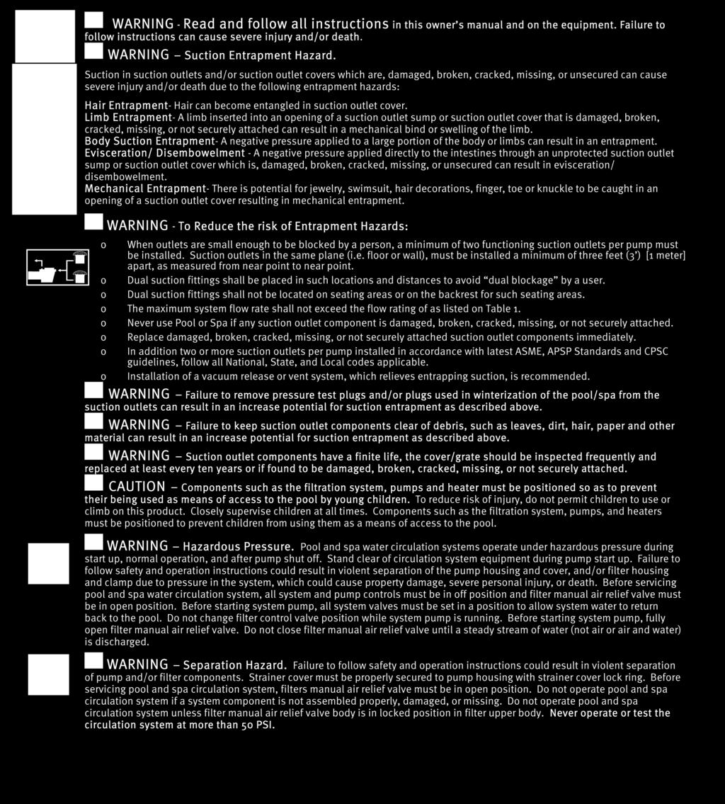
48 45


49 46
OmniLogic. Automation and Chlorination. Installation Manual. Contents HLBASE
 092472 RevB OmniLogic Automation and Chlorination Installation Manual Contents Before You Begin...1 Overview...1 Mounting Equipment...4 Plumbing...6 Wiring...10 Preparing Pool/Spa Water...21 System Startup...23
Installation Manual for models
 Automation and Chlorination Installation Manual for models PL-PS-4 PL-PS-8 PL-PS-16 PL-PS-8-V PL-PS-16-V G LDLINE CON TROLS www.goldlinecontrols.com IMPORTANT SAFETY INSTRUCTIONS When using this electrical
Aqua Plus 16v. Automation and Chlorination. Installation Manual. Contents PL-PLUS-16V
 092456 RevD Aqua Plus 16v Automation and Chlorination \ Installation Manual Contents Introduction...2 Pool Chemistry...3 Installation...6 Configuration...24 System Startup...45 Warranty...50 PL-PLUS-16V
Automation and Chlorination. Installation Manual. for model PL-P-4 CON TROLS.
 Automation and Chlorination Installation Manual for model PL-P-4 G LDLINE CON TROLS www.goldlinecontrols.com IMPORTANT SAFETY INSTRUCTIONS When using this electrical equipment, basic safety precautions
Aqua Logic LDLINE. Installation Manual for models AQ-LOGIC-PS-4 AQ-LOGIC-PS-8. Automation and Chlorination CONTROLS INC.
 Aqua Logic Automation and Chlorination Installation Manual for models AQ-LOGIC-PS-4 AQ-LOGIC-PS-8 G LDLINE CONTROLS INC. www.goldlinecontrols.com 888-921-7665 IMPORTANT SAFETY INSTRUCTIONS When using this
Hayward. OnCommand. Installation Manual. Automation. for models ONCOM ONCOM-ACT ONCOM-RC ONCOM-ACT-RC.
 Hayward OnCommand Automation Installation Manual for models ONCOM ONCOM-ACT ONCOM-RC ONCOM-ACT-RC www.haywardnet.com IMPORTANT SAFETY INSTRUCTIONS When using this electrical equipment, basic safety precautions
Gunite & Fiberglass Pools
 Electrical Wiring The Pro Logic Control Center and PS-16 Expansion Unit require both high and low voltage connections. Low voltage connections will be made to actuators, sensors, remote keypad, etc. High
Aqua Plus. Installation Manual for model. Aqua Plus Programming Flow Chart. Automation and Chlorination AQL-PLUS AQL-PLUS-20 G CON TROLS
 Aqua Plus Programming Flow Chart denotes conditional items Aqua Plus Automation and Chlorination Aqua Plus only Aqua Plus only (actuator and remote display not included - order separately) Installation
Aqua Logic. Operation Manual. Automation and Chlorination AQL-P CON TROLS. for model
 Aqua Logic Automation and Chlorination (actuators, cell & remote display not included - order separately) Operation Manual for model AQL-P-4 G LDLINE CON TROLS www.goldlinecontrols.com 888-921-7665 IMPORTANT
VS Omni. Pool Automation Control. Installation Manual HL32950VVSP HL32900VSP HL26720VSP HL23520VSP HL23510VSP
 092680 RevB VS Omni Pool Automation Control Installation Manual Contents HL32950VVSP HL32900VSP HL26720VSP HL23520VSP HL23510VSP Before you Begin...3 Mounting...7 Plumbing...9 Wiring...10 Startup...22
Automation and Chlorination. Operation Manual. for models PL-PLUS PL-PLUS CON TROLS
 Automation and Chlorination Operation Manual for models PL-PLUS PL-PLUS-20 G LDLINE CON TROLS www.goldlinecontrols.com 888-921-7665 IMPORTANT SAFETY INSTRUCTIONS When using this electrical equipment, basic
Aqua Plus 16v. Operation Manual for model. Automation and Chlorination PL-PLUS-16V.
 Aqua Plus 16v Automation and Chlorination Operation Manual for model PL-PLUS-16V www.haywardnet.com IMPORTANT SAFETY INSTRUCTIONS When using this electrical equipment, basic safety precautions should always
Pro Logic. Automation and Chlorination. Operation Manual. Contents PL-PS-16-V
 092331D RevH Pro Logic Automation and Chlorination \ Operation Manual Contents Introduction...2 Operation...4 Pool Chemistry...43 Troubleshooting...48 Warranty...54 PL-PS-4 PL-PS-8 PL-PS-16 PL-PS-8-V PL-PS-16-V
PRO LOGICTM. Automation and Chlorination. Operation Manual for models PL-PS-16-V CON TROLS
 PRO LOGICTM Automation and Chlorination Operation Manual for models PL-PS-4 PL-PS-8 PL-PS-16 PL-PS-8-V PL-PS-16-V G LDLINE CON TROLS www.goldlinecontrols.com 888-921-7665 IMPORTANT SAFETY INSTRUCTIONS
Aqua Plus. Automation and Chlorination. Operation Manual PL-PLUS PL-PLUS-20
 092360D RevH Aqua Plus Automation and Chlorination \ Operation Manual Contents Introduction...2 Operation...4 Chemistry...32 Troubleshooting...37 Warranty...42 PL-PLUS PL-PLUS-20 Hayward Pool Products
Aqua Logic. Operation Manual. Automation and Chlorination AQL-PS-16-V for models CON TROLS
 Aqua Logic Automation and Chlorination (actuators, cell & remote display not included - order separately) Operation Manual AQL-PS-4 AQL-PS-8 AQL-PS-16 for models AQL-PS-8-V AQL-PS-16-V G LDLINE CON TROLS
OmniHub. Pool Automation Control. Installation Manual HLOMNIHUB
 092711 RevA OmniHub Pool Automation Control Installation Manual Contents Before you Begin...3 Mounting...8 Plumbing...10 Wiring...11 Startup...23 Configuration...24 HLOMNIHUB Hayward Pool Products 620
Aqua Plus. Operation Manual for model G CON TROLS. Automation and Chlorination AQL-PLUS AQL-PLUS-20 TEST IDEAL RANGE ADJUSTMENT REQUIRED
 TEST IDEAL RANGE ADJUSTMENT REQUIRED Aqua Plus Automation and Chlorination Free Chlorine 1.0-3.0 ppm Turn output dial up to increase, down to decrease -OR- increase or decrease pump filtration time. ph
Hayward ECOMMAND. Installation Manual. Automation.
 Hayward ECOMMAND Automation Installation Manual www.haywardnet.com IMPORTANT SAFETY INSTRUCTIONS When using this electrical equipment, basic safety precautions should always be followed, including the
Pro Logic. Operation Manual for models. Automation and Chlorination PL-PS-16-V TEST IDEAL RANGE ADJUSTMENT REQUIRED
 Quarterly Monthly Weekly TEST IDEAL RANGE ADJUSTMENT REQUIRED Free Chlorine 1.0-3.0 ppm ph 7.2-7.8 Alkalinity Salt 80-120 ppm Raise desired output % to increase, lower desired output % to decrease -OR-
Owner s Manual RD432-0 Chemical Controller
 Owner s Manual RD432-0 Chemical Controller Table of Contents I. Introduction page 2 A. Water Chemistry page 2 B. Safety page 3 C. System Components page 4 D. Specifications page 7 E. Controller Panel Descriptions
AquaRite. Troubleshooting Guide Residential. TSG-AQR159d. Copyright 2017 Hayward Industries Inc.
 AquaRite Troubleshooting Guide Residential TSG-AQR159d Copyright 2017 Hayward Industries Inc. Safety Precautions Warning! High Voltage Electrocution Hazard Hazardous voltage can shock, burn, cause serious
OnCommand. Automation. Operation Manual ONCOM ONCOM-ACT ONCOM-RC ONCOM-ACT-RC ONCOM-POD2 ONCOM-ACT-POD2
 092442A RevC OnCommand Automation \ Operation Manual Contents Introduction...2 Operation...3 Troubleshooting...29 Warranty...34 ONCOM ONCOM-ACT ONCOM-RC ONCOM-ACT-RC ONCOM-POD2 ONCOM-ACT-POD2 Hayward Pool
OWNER S MANUAL. Vintage Signature Series models: AC750, AC1050, AC1100, AC1250, AC1500, AC1750. Proudly Made in the USA.
 OWNER S MANUAL Vintage Signature Series models: AC750, AC1050, AC1100, AC1250, AC1500, AC1750 Proudly Made in the USA support@aquacomfort.com 888-475-7443 Manufacturing High Quality, High Efficiency Heat
M770 ph Controller Owner s Manual
 M770 ph Controller Owner s Manual Table of Contents I. Introduction page 2 A. Water Chemistry page 2 B. Safety page 3 C. System Components page 4 D. Specifications page 7 E. Controller Panel Descriptions
DIGIHEAT IN LINE HEATERS
 DIGIHEAT IN LINE HEATERS Installation and operation manual for Single & Three Phase Models Offices - Australia NSW - Sydney (Head Office) Tel: +61 2 9898 8600 QLD - Brisbane Tel: +61 7 3299 9900 VIC/TAS
ProLogic /AquaLogic. Consumer Troubleshooting Guide. CTSG-PL447a. Copyright 2016 Hayward Industries Inc.
 ProLogic /AquaLogic Consumer Troubleshooting Guide CTSG-PL447a Copyright 2016 Hayward Industries Inc. Safety Precautions Warning! High Voltage Electrocution Hazard Hazardous voltage can shock, burn, cause
PORTAPAC / DELTA HOT. Installation and Operation Manual. ! WARNING
 PORTAPAC / DELTA HOT Installation and Operation Manual! WARNING This equipment must be installed and serviced by a qualified technician. Improper installation can create electrical hazards which could
Wave Series. Installation and User Guide. PE950 Hand-Held Remote Transceiver PE650 Panel-Mounted Transceiver
 Wave Series PE950 Hand-Held Remote Transceiver PE650 Panel-Mounted Transceiver Intermatic, Inc. 7777 Winn Road Spring Grove, Illinois 60081-9698 www.intermatic.com Intermatic Customer Service: 815-675-7000
Ozone Generator Systems
 PZ2-1 & PZ2-2 - Commercial and Residential Pools & Spas Ozone Generator Systems INSTALLATION GUIDE and OPERATION MANUAL T. O3 NATURAL TECHNOLOGY Reduces Chemical Usage, Improves Sanitation Produces Crystal
Automation. All the control you ll need to create the ultimate pool experience.
 Automation All the control you ll need to create the ultimate pool experience. Hayward automates virtually everything, for a better backyard experience and more time to enjoy it. Hayward offers a line
Section 1. Information before installation
 2 3 Section 1. Information before installation 1.1 General delivery conditions All equipment, even carriage and packaging paid, is shipped at the recipient s risk. If damaged caused during transport is
Ozone Generator Systems
 PZ2-4V - Commercial and Residential Pools & Spas Ozone Generator Systems INSTALLATION GUIDE and OPERATION MANUAL T. O3 NATURAL TECHNOLOGY Reduces Chemical Usage, Improves Sanitation Produces Crystal Clear
Quick Start Guide. For product manuals and further installation / operation procedures visit
 Quick Start Guide For product manuals and further installation / operation procedures visit www.aquacal.com Important Read This Guide Before Installing or Operating Heat Pump LTP0093 Rev 1 03/21/2014 Page
PZ1, PZ3 & PZ6 Installation Guide
 PZ1, PZ3 & PZ6 Installation Guide PROZONE INTERNATIONAL, INC. Ozone Water Purification Systems INSTALLATION GUIDE Prozone PZ1, PZ3 and PZ6 Series Ozone Generator Systems SAFETY READ AND FOLLOW ALL INSTRUCTIONS.
IMPORTANT SAFETY INSTRUCTIONS READ AND FOLLOW ALL INSTRUCTIONS SAVE THESE INSTRUCTIONS
 Operating Manual MODEL RC554X AND 554230 ORP Digital Controller FEED ALERT ORP FLOW AUTO MODE SET LEVEL FEED TIME FLOW SWITCH ORP ORP OUTPUT POWER IMPORTANT SAFETY INSTRUCTIONS READ AND FOLLOW ALL INSTRUCTIONS
PZ2 Series Manual. PROZONE INTERNATIONAL, Inc. Ozone Water Purification Systems. INSTALLATION GUIDE and OPERATION MANUAL. Prozone PZ2 Series
 PZ2 Series Manual PROZONE INTERNATIONAL, Inc. Ozone Water Purification Systems INSTALLATION GUIDE and OPERATION MANUAL Prozone PZ2 Series Ozone Generator Systems SAFETY READ AND FOLLOW ALL INSTRUCTIONS.
IMPORTANT SAFETY INSTRUCTIONS READ AND FOLLOW ALL INSTRUCTIONS SAVE THESE INSTRUCTIONS
 Operating Manual MODEL RC554P AND 554200 ph Digital Controller FEED ph FLOW ALERT AUTO MODE SET LEVEL FEED TIME ph CALIB FLOW SWITCH ph ph OUTPUT POWER IMPORTANT SAFETY INSTRUCTIONS READ AND FOLLOW ALL
M790 ph/orp Controller. Owner s Manual
 M790 ph/orp Controller Owner s Manual Table of Contents I. Introduction page 2 A. Water Chemistry page 2 B. Safety page 3 C. System Components page 4 D. Specifications page 7 E. Controller Panel Descriptions
DRAFT INSTALLATION INSTRUCTIONS. Solid-State Series !! NOTE!! Covers the following models: Refer to INSERT for additional information
 INSTALLATION INSTRUCTIONS Solid-State Series!! NOTE!! Covers the following models: " CS6100 - CS7100 " CS6200 - CS9200 " CS6220 - CS9220 " CS6230 - CS9230 " CS6500 - CS7500 " CS6330 - CS9300 " CS9400 -
Next Generation Corona Discharge Installation & Operation Manual
 Next Generation Corona Discharge Installation & Operation Manual 4-2319-01 Rev.A IMPORTANT SAFETY INSTRUCTIONS READ & FOLLOW ALL INSTRUCTIONS Read this manual completely before attempting installation.
OWNER S MANUAL. Models: AC110, AC125, AC150 made from 2003 through Proudly Made in the USA
 OWNER S MANUAL Models: AC110, AC125, AC150 made from 2003 through 2010 Proudly Made in the USA support@aquacomfort.com www.aquacomfort.com/service-and-support/ (888) 475-7443 Manufacturing High Quality,
MODEL ORP/pH Digital Controller
 MODEL 554000 ORP/pH Digital Controller Operating Manual Rola-Chem Digital Controller PN 554102 6/01/2012 Page: 1 of 20 QUICK START REFERENCE Use this section for reference - please read all safety instructions
EcoMaster - Residential Pools up to 40,000 Gallons
 - Residential Pools up to 40,000 Gallons INSTALLATION/ OPERATION GUIDE Reduces Chemical Usage, Improves Sanitation Produces Crystal Clear Water Copyright 2013 Prozone Water Products: 3004 11 th Ave. -
INSTALLATION INSTRUCTIONS FOR 7330C740 FLUSH MOUNT CEILING ASSEMBLY
 INSTALLATION INSTRUCTIONS FOR 7330C740 FLUSH MOUNT CEILING ASSEMBLY TABLE OF CONTENTS Warnings...3 Package Contents...3 General Information...3 Supply Ducting And Registers...3 Routing 115 VAC Wiring...5
INSTALLATION INSTRUCTIONS
 INSTALLATION INSTRUCTIONS VARIABLE SPEED BOOSTER PUMP IMPORTANT SAFETY INSTRUCTIONS READ AND FOLLOW ALL INSTRUCTIONS SAVE THESE INSTRUCTIONS IMPORTANT SAFETY INFORMATION WARNING: RISK OF ELECTRICAL SHOCK
OWNER S MANUAL. Vintage Classic HEAT COOL models. Proudly Made in the USA
 OWNER S MANUAL Vintage Classic HEAT COOL models Proudly Made in the USA support@aquacomfort.com www.aquacomfort.com/service-and-support 888-475-7443 Manufacturing High Quality, High Efficiency Heat Pump
Genus III Pool and Spa Controller
 Genus III Pool and Spa Controller INSTALLATION & OPERATING INSTRUCTIONS AstralPool Australia Pty. Limited. A.B.N. 97 007 284 504 Infmation and specifications subject to change without notice. Melbourne:
EcoMaster - Residential Pools up to 40,000 Gallons
 - Residential Pools up to 40,000 Gallons INSTALLATION/ OPERATION GUIDE Reduces Chemical Usage, Improves Sanitation Produces Crystal Clear Water PROZONE Copyright 2018 Prozone Water Products: 3004 11 th
Contents. Specifications. Description SV HP 55 SV HP 90. Specifications Warnings Introduction Overview... 4
 Contents Specifications Specifications... 1 Warnings... 2 Introduction... 3 Overview... 4 Installation Instructions... 5 Cable Connections... 6 Plumbing Diagram... 7 Electrical Wiring Diagram... 8 SV System
READ AND FOLLOW ALL INSTRUCTIONS SAVE THESE INSTRUCTIONS
 READ AND FOLLOW ALL INSTRUCTIONS SAVE THESE INSTRUCTIONS 1 IMPORTANT SAFETY INSTRUCTIONS Read the instructions The appliance is not to be used by persons (including children) with reduced physical, sensory
M820 ph/dual ORP Controller. Owner s Manual
 M820 ph/dual ORP Controller Owner s Manual Table of Contents I. Introduction page 2 A. Water Chemistry page 2 B. Safety page 3 C. System Components page 4 D. Specifications page 7 E. Controller Panel Descriptions
Closing procedures for in-ground pools
 Closing procedures for in-ground pools Note: Carefully read this entire document before proceeding with the closure of your pool. In order to avoid unpleasant surprises, please check with your insurance
Owner s Manual PRINTED IN CANADA 05/2009
 Owner s Manual PRINTED IN CANADA 05/2009 Table of contents Introduction 2 General Safety Instructions 4 Installation Instructions Location 6 Water piping 7 Electrical 7 Bonding 8 Bonding and plumbing
IMPORTANT SAFETY INSTRUCTIONS READ AND FOLLOW ALL INSTRUCTIONS SAVE THESE INSTRUCTIONS
 Operating Manual MODELS RC554XP AND 554000 ORP/pH Digital Controller FEED ph ALERT FEED ORP ALERT F LOW ph MODE AUTO FEED ONCE SET LEVEL FEED TIME HI LOW ph CALIB ORP ph ORP IMPORTANT SAFETY INSTRUCTIONS
Heat Transfer Products, Inc. 120 Braley Road East Freetown, MA The first totally integrated multiple boiler management control.
 Heat Transfer Products, Inc. 120 Braley Road East Freetown, MA 02717 The first totally integrated multiple boiler management control. USING THIS MANUAL USING THIS MANUAL A. INSTALLATION SEQUENCE Follow
Xcelsior Spa Pool System
 Davey Repair or Replacement Guarantee In the unlikely event in Australia or New Zealand that this Davey product develops any malfunction within two years of the date of original purchase due to faulty
Installation in Standard & Variable Speed Indoor Air Handlers IMPORTANT
 H6HK Series Electric Heater Kit INSTALLATION INSTRUCTIONS Installation in Standard & Variable Speed Indoor Air Handlers IMPORTANT These instructions are primarily intended to assist qualified individuals
SuperStor Glass Lined Storage Tank
 SuperStor Glass Lined Storage Tank INSTALLATION MAINTENANCE TROUBLESHOOTING PARTS Storage Tank Models GL-50 / GL-80* GL-119* / GL-175* For Residential and Commercial Use *Available in Metal Jacketed ASME
Clear Comfort Residential Pool & Spa Sanitization System Installation, Operations & Maintenance Manual
 Clear Comfort Residential Pool & Spa Sanitization System Installation, Operations & Maintenance Manual IMPORTANT SAFETY INSTRUCTIONS For Further Assistance Contact Us: 303.872.4477 support@clearcomfort.com
Table of Contents 1. OVERVIEW SYSTEM LAYOUT SPECIFICATIONS FUNCTION... 11
 Table of Contents 1. OVERVIEW... 3 2. SYSTEM LAYOUT... 4 3. SPECIFICATIONS... 8 3.1 SYSTEM COMPONENTS...9 3.2 PLC INPUTS AND OUTPUTS...9 3.3 FUNCTION KEYS...10 3.4 DEFAULT SET POINTS AND TIMERS...10 4.
INTELLILEVEL AUTOMATIC WATER LEVELING SYSTEM FOR POOL AND SPA
 INTELLILEVEL AUTOMATIC WATER LEVELING SYSTEM FOR POOL AND SPA INSTALLATION AND USER S GUIDE IMPORTANT SAFET Y INSTRUCTIONS READ AND FOLLOW ALL INSTRUCTIONS SAVE THESE INSTRUCTIONS 2 CUSTOMER SERVICE /
MP920 SALT CHLORINATOR
 MP920 SALT CHLORINATOR Index 1 Safety Instructions... 3 1.1 Warnings... 3 2 EC Conformity... 3 3 System Contents... 3 4 Installation... 4 4.1 Hydraulic Installation... 4 4.1.1 Electrolysis Cell... 4 4.2
Installation and Operation Manual. ACF-18 Automatic Chlorinating Feeder
 Installation and Operation Manual ACF-18 Automatic Chlorinating Feeder Operating Specifications Inlet Flow: 1.0-1.5 gpm Outlet Flow: = Inlet Flow Inlet Pressure: 10-45 psi Maximum Output: 26 lbs. of Available
HydroRite UVO 3. Troubleshooting Guide Residential. TSG-UVO158a. Copyright 2015 Hayward Industries Inc.
 HydroRite UVO 3 Troubleshooting Guide Residential TSG-UVO158a Copyright 2015 Hayward Industries Inc. Safety Precautions Warning! When installing and using this electrical equipment, basic safety precautions
Vacuum-ultraviolet Ozone Systems. Installation & Operation Manual. Model OZ-SPA
 OzoneAX 3 T Vacuum-ultraviolet Ozone Systems Installation & Operation anual odel OZ-SPA A. Important Safety Instructions IPORTANT SAFETY INSTRUCTIONS When using this electrical equipment, basic safety
CAT Water Quality Controller. Owner s Manual. Contents CAT-5500
 092601 RevC CAT 5500 Water Quality Controller \ Owner s Manual Contents Introduction...2 Installation...4 Pool Chemistry...7 Configuration...7 System Maintenance...31 Network Communications...32 Troubleshooting...36
HT-2 / 9600 Series Control Contents
 HT-2 / 9600 Series Control Contents Tools & Parts Tools Required Parts Required Error Messages 3 Flashing Dots Pressure or Flow Switch Not Activated Pressure or Flow Switch Activated Temperature Sensor
Ozone plus UV Sanitation System Installation & Operations Manual
 Ozone plus UV Sanitation System Installation & Operations Manual 3580 Sueldo Street, San Luis Obispo, CA 93401 800.676.1335 o3info@delozone.com www.delozone.com 4-2305-01 Rev.B TABLE OF CONTENTS SECTION
SuperStor Ultra Stainless Steel Storage Tank
 SuperStor Ultra Stainless Steel Storage Tank INSTALLATION START-UP MAINTENANCE PARTS Storage Tank Models SSU-30CB / SSU-45CB SSU-60CB / SSU-80CB / SSU-119CB For Residential and Commercial Use This manual
Heat Pumps. English. Models: M1, M2, M3, M4, M5. User Manual
 English User Manual Heat Pumps Models: M1, M2, M3, M4, M5 For product manuals and further installation operation procedure contact poolcalor@yahoo.com.br S E C T I O N 1 - G E N E R A L I N F O R M AT
INSTALLATION INSTRUCTIONS FOR 8330*63**, 8530*63** CHILLGRILLE FLUSH MOUNT CEILING ASSEMBLY
 RV Products Division INSTALLATION INSTRUCTIONS FOR 8330*63**, 8530*63** CHILLGRILLE FLUSH MOUNT CEILING ASSEMBLY DESIGNED AND MANUFACTURED BY THE MAKERS OF COLEMAN -MACH AIR CONDITIONERS TABLE OF CONTENTS
1F Non-Programmable Electronic Digital Multi-Stage Thermostat INSTALLATION AND OPERATION INSTRUCTIONS
 1F83-261 Non-Programmable Electronic Digital Multi-Stage Thermostat INSTALLATION AND OPERATION INSTRUCTIONS Operator: Save these instructions for future use! FAILURE TO READ AND FOLLOW ALL INSTRUCTIONS
INSTALLATION INSTRUCTIONS FOR 6532 SERIES PACKAGE HEAT PUMP
 INSTALLATION INSTRUCTIONS FOR 6532 SERIES PACKAGE HEAT PUMP RV Products A Division of Airxcel, Inc. P.O. Box 4020 Wichita, KS 67204 1976-360 (1-02) PP TABLE OF CONTENTS 1. Warnings......................................................
Arch Feeder: Installation Manual
 Arch Feeder: Installation Manual Model #A300N Arch Chemicals, Inc. 1200 Lower River Road, P.O. Box 800 Charleston, TN 37310-0800 Product Stewardship MAKING THE WORLD A BETTER PLACE Arch is committed to
IF79 CAUTION CONTENTS YOUR THERMOSTAT REPLACES 1 PREPARATIONS. Installation Instructions for. Heating & Air Conditioning
 CONTENTS Installation Instructions for Heating & Air Conditioning IF79 n- Programmable Heat Pump Thermostat Preparations... 1 Thermostat Details... 1 Removing Old Thermostat... 1-2 Mounting and Wiring...
1F Non-programmable Electronic Digital Heat Pump Thermostat INSTALLATION AND OPERATION INSTRUCTIONS
 FAILURE TO READ AND FOLLOW ALL INSTRUCTIONS CAREFULLY BEFORE INSTALLING OR OPERATING THIS CONTROL COULD CAUSE PERSONAL INJURY AND/OR PROPERTY DAMAGE. DESCRIPTION Your new White-Rodgers Digital Thermostat
READ AND FOLLOW ALL INSTRUCTIONS SAVE THESE INSTRUCTIONS
 READ AND FOLLOW ALL INSTRUCTIONS SAVE THESE INSTRUCTIONS International Patent #9,938,166 Patented Micro-Ozone cell ozone technology: Patent #8367007 1 IMPORTANT SAFETY INSTRUCTIONS Read the maintenance
SAMPLE MANUAL - INSTALLATION - FOR REFERENCE ONLY. ChemScan mini Analyzer. Parameter. Method #### Installation, Operation & Maintenance Manual
 Parameter Method ####, Operation & Maintenance Manual Rev 3/26/2018 Contact Information Document Information Customer Name: Plant Name/Location: Date: Analyzer Serial #: ASA, Inc. (Applied Spectrometry
HAYWARD POOL PRODUCTS, INC. 620 Division Street Elizabeth, NJ Tel:
 IS270T-05 Rev. B OWNER S MANUAL INSTALLATION, OPERATION & PARTS MODEL S270T PRO SERIES HIGH-RATE SAND FILTER Basic safety precautions should always be followed, including the following: Failure to follow
INSTALLATION INSTRUCTIONS FOR 6536 SERIES TWO TON PACKAGED HEAT PUMP
 INSTALLATION INSTRUCTIONS FOR 6536 SERIES TWO TON PACKAGED HEAT PUMP TABLE OF CONTENTS 1. Warnings...2 2. Component Match-Up...2 3. Unit Depiction Figures...3 4. Blower Performance Data...5 5. General
THE PUMP THEY NEED PLUS THE POOL CONTROL THEY WANT.
 THE PUMP THEY NEED PLUS THE POOL CONTROL THEY WANT. VS OMNI PUMPS WITH SMART POOL CONTROL ARE THE SIMPLEST WAY TO ADD TO POOLS AND SPAS. Energy-efficient VS Omni pumps offer smart control for up to four
Refrigeration Controller Operator s Manual (HRC) PO Box 6183 Kennewick, WA
 PO Box 6183 Kennewick, WA") Refrigeration Controller Operator s Manual (HRC) PO Box 6183 Kennewick, WA 99336 www.jmcvr.com 1-509-586-9893 Table of Contents TABLE OF FIGURES...1 OVERVIEW OF THE HRC CAPABILITIES...2 INSTALLATION AND
Refrigeration Controller Operator s Manual (HRC) PO Box 6183 Kennewick, WA 99336 www.jmcvr.com 1-509-586-9893 Table of Contents TABLE OF FIGURES...1 OVERVIEW OF THE HRC CAPABILITIES...2 INSTALLATION AND
Spa Touch Control Panel with 2000, 2100 controllers. (Spa Owner s Manual insert)
") Spa Touch Control Panel with 2000, 2100 controllers (Spa Owner s Manual insert) P.N. 7876B February 11, 2015 For Spas equipped with BP2000, BP2100 controllers and Spa Touch panel. Spa Touch Control Panel
Spa Touch Control Panel with 2000, 2100 controllers (Spa Owner s Manual insert) P.N. 7876B February 11, 2015 For Spas equipped with BP2000, BP2100 controllers and Spa Touch panel. Spa Touch Control Panel
INSTALLATION INSTRUCTIONS FOR MOUNTING KIT
 RV Products Division INSTALLATION INSTRUCTIONS FOR 8330-5501 MOUNTING KIT 8330-752 CONTROL BOX KIT (12 VDC COOL ONLY) 9330B755 CONTROL BOX KIT (12 VDC HEAT/COOL) 8530-750 CONTROL BOX KIT (24 VAC COOL ONLY)
INSTALLATION INSTRUCTIONS FOR 8330*5511 MOUNTING KIT
 RV Products Division INSTALLATION INSTRUCTIONS FOR 8330*5511 MOUNTING KIT 8330-752 CONTROL BOX KIT (12 VDC COOL ONLY) 9330A755 CONTROL BOX KIT (12 VDC HEAT/COOL) 8530-750 CONTROL BOX KIT (24 VAC COOL ONLY)
SP400P & SP601. User s Guide. Models: SP400P, Q400PAU-10, Q400PAU-15 SP601AU-15, SP601AU-15T Q601AU-20, SP601AU-20T Q601AU-30, SP601AU-30T
 8 Self-Diagnostic Error Codes The Spa Power controller has extensive self diagnostic capabilities. In the event of a problem it will indicate an error number according to the nature of the problem. The
2 THERMOSTAT DETAILS 3 REMOVING OLD THERMOSTAT
 CONTENTS Installation Instructions for Heating & Air Conditioning 1F79 n-programmable Heat Pump Thermostat Preparations... 1 Thermostat Details... 1 Removing Old Thermostat... 1-2 Mounting and Wiring...
SPA HEATER INSTALLATION, OPERATION AND MAINTENANCE
 SPA INSTALLATION, OPERATION AND MAINTENANCE MODELS: ST SERIES 5.5 & 11kW 240V SINGLE PHASE BEFORE YOU BEGIN CHECK ALL ELECTRICAL CONNECTIONS TO ALL COMPONENTS WITHIN THE FOR TIGHTNESS. CONNECTIONS CAN
Installation, Operation & Maintenance Manual. Wash System
 Installation, Operation & Maintenance Manual Wash System Kleen Flo Wash System Installation, Operation & Maintenance Manual CONTENTS Introduction and Overview... 3 Pipeline Wash System Features... 5 Wash
AC THOR. Assembly Instructions
 AC THOR Photovoltaic-Power-Manager for hot water and space heating Assembly Instructions The Operation Manual of the device is available at www.my-pv.com. The following device key is required for online
Compool. Cp3600 POOL-SPA CONTROL SYSTEM. Installation & Operating Instructions 02/10/
 Compool Cp3600 POOL-SPA CONTROL SYSTEM Installation & Operating Instructions 02/10/98 941-1096 Compool Cp3600 1 Table of Contents Safety Notice............................................................
PME. Series Enclosures. Battery Enclosure (BE) Field Upgrade Installation Instructions. Effective: January, Alpha Technologies
 Field Upgrade Installation Instructions. Effective: January, Alpha Technologies") PME Series Enclosures Battery Enclosure (BE) Field Upgrade Installation Instructions Effective: January, 2004 Alpha Technologies Power Alpha Technologies. Protecting The Power in Communications. Preface
PME Series Enclosures Battery Enclosure (BE) Field Upgrade Installation Instructions Effective: January, 2004 Alpha Technologies Power Alpha Technologies. Protecting The Power in Communications. Preface
Technical Manual. VFD / Cabinet Heater Upgrade 110 VAC Heater to 12 VDC Heater. Provided by: Chart Inc.
 Technical Manual VFD / Cabinet Heater Upgrade 110 VAC Heater to 12 VDC Heater Provided by: Chart Inc. 407 7th Street NW New Prague, MN 56071 USA (800) 400-4683 Part Number 20977233 Rev. A 2016 Chart Inc.
INSTALLATION INSTRUCTIONS FOR 6797A737 HEAT PUMP FLUSH MOUNT CEILING PLENUM
 INSTALLATION INSTRUCTIONS FOR 6797A737 HEAT PUMP FLUSH MOUNT CEILING PLENUM TABLE OF CONTENTS Warnings............................................................................... 2 Package Contents........................................................................
FOR THE RECORD. You should record the model and serial numbers, which can be found on the back of the unit, for future reference.
 FOR THE RECORD You should record the model and serial numbers, which can be found on the back of the unit, for future reference. Warranty: 18 mo. on unit and 1 year on check valve assembly Model: The Ozone
THIS KIT CONTAINS: Part: Qty: Description: a. 1 MagnaPool Control Centre b. 1 Hydroxinator cell c. 1 Power pack bracket d. 2 Reducing bushes
 Installation and Operator Guide THIS KIT CONTAINS: Part: Qty: Description: a. 1 MagnaPool Control Centre b. 1 Hydroxinator cell c. 1 Power pack bracket d. 2 Reducing bushes WELCOME TO ZODIAC Congratulations
Hand Dryer Installation & User Manual
 Hand Dryer Installation & User Manual Please read instructions in conjunction with the illustrations Please save these instructions. Safety & Guidance notes Important:- Read all these instructions before
CONTENTS CONSIDERATIONS. General Plumbing Component Connection ILLUSTRATION. Control System CONFIGURATION. Voltage Verification CONNECTION
 AIR SERIES SYSTEM INSTALLATION MANUAL CONTENTS CONSIDERATIONS General Plumbing Component Connection 2 2 2 ILLUSTRATION Control System 3 CONFIGURATION Voltage Verification 4 CONNECTION Component Connection
Compool. Cp3800 POOL-SPA CONTROL SYSTEM. Installation & Operating Instructions 11/07/
 Compool Cp3800 POOL-SPA CONTROL SYSTEM Installation & Operating Instructions 11/07/97 941-1064 Compool Cp3800 1 Table of Contents Safety Notice............................................................