OmniLogic. Automation and Chlorination. Installation Manual. Contents HLBASE
|
|
|
- Harvey Stokes
- 5 years ago
- Views:
Transcription

1 RevB OmniLogic Automation and Chlorination Installation Manual Contents Before You Begin...1 Overview...1 Mounting Equipment...4 Plumbing...6 Wiring...10 Preparing Pool/Spa Water...21 System Startup...23 Configuration Wizard...24 HLBASE Hayward Pool Products 620 Division Street, Elizabeth NJ
2 IMPORTANT SAFETY INSTRUCTIONS When using this electrical equipment, basic safety precautions should always be followed, including the following: READ AND FOLLOW ALL INSTRUCTIONS WARNING: Disconnect all AC power during installation. WARNING: Water in excess of 100 degrees Fahrenheit may be hazardous to your health. WARNING: To reduce the risk of injury, do not permit children to use this product unless they are closely supervised at all times. WARNING: Do not use the OmniLogic to control fire pits or related fire equipment. A green colored terminal marked Grounding is located inside the wiring compartment. To reduce the risk of electric shock, this terminal must be connected to the grounding means provided in the electric supply service panel with a continuous copper wire equivalent in size to the circuit conductors supplying the equipment. One bonding lug for US models is provided on the external surface. To reduce the risk of electric shock, connect the local common bonding grid in the area of the swimming pool, spa, or hot tub to these terminals with an insulated or bare copper conductor not smaller than 8 AWG US / 6 AWG Canada. All field installed metal components such as rails, ladders, drains, or other similar hardware within 3 meters of the pool, spa or hot tub shall be bonded to the equipment grounding bus with copper conductors not smaller than 8 AWG US / 6 AWG Canada. SAVE THESE INSTRUCTIONS
3 FCC Statement This device complies with part 15 of the FCC rules. Operation is subject to the following two conditions: (1) This device may not cause harmful interference, and (2) this device must accept any interference received, including interference that may cause undesired operation. Changes or modifications not expressly approved by Hayward could void the user s authority to operate this equipment. NOTE: This equipment has been tested and found to comply with the limits for a Class B digital device, pursuant to Part 15 of the FCC Rules. These limits are designed to provide reasonable protection against harmful interference in a residential installation. This equipment generates, uses and can radiate radio frequency energy and, if not installed and used in accordance with the instructions, may cause harmful interference to radio communications. However, there is no guarantee that interference will not occur in a particular installation. If this equipment does cause harmful interference to radio or television reception, which can be determined by turning the equipment off and on, the user is encouraged to try to correct the interference by one or more of the following measures: -- Reorient or relocate the receiving antenna. -- Increase the separation between the equipment and receiver. -- Connect the equipment into an outlet on a circuit different from that to which the receiver is connected. -- Consult the dealer or an experienced radio / TV technician for help. Industry Canada Statement This Class B digital apparatus complies with Canadian ICES-003. Cet appareil numérique de la classe B est conforme à la norme NMB-003 du Canada. The term IC before the certification / registration number only signifies that the Industry Canada technical specifications were met.
4 Table of Contents Introduction Preparing Mounting Equipment Plumbing Electrical Wiring Pool/Spa Water Installation Steps...3 OmniLogic Enclosure...4 Temperature Sensors...5 Optional Chlorination...5 Optional HL-CHEM Sensing Kit...5 Optional AQL-CHEM2 ph Dispensing...5 Optional HLWALLMOUNT...5 Optional HLWLAN...5 Optional Valve Actuators...6 Pool/Spa Configuration...6 TurboCell...9 Flow Switch...9 Main Service...11 Grounding and Bonding...11 Circuit Breaker Installation and Wiring...11 General Purpose Outlet...11 OmniLogic Power...11 Pool Equipment Connection Table...12 High Voltage Pool Equipment...13 Low Voltage Wiring...14 General Water Chemistry...21 Salt...22 Final Steps Startup and Configuration Warranty System Startup...23 Startup and Configuration Wizard...24 Bodies of Water...25 Filter Pumps...26 Heaters...27 HL-CHEM...28 Chlorinator...29 Cleaners...29 Water Features...30 ColorLogic Lights...31 Other Lights...31 Accessories...31 Sensors...32 Backyard Accessories...33 Interlocks...33 OmniLogic Limited Warranty...35
5 Before you Begin What s Included Before attempting to install the OmniLogic system, check that the following components have been included in the package: OmniLogic Electronics Unit (3) Temperature sensors with 15 ft. (5m) cable, hose clamp Ferrite bead for ethernet cable Spare main board fuses What s NOT Included Some of the additional items that you may need to complete an installation include: Circuit breakers None are included with control see page 11 and inside door label for suitable breakers Wire 4-conductor cable for connection to optional wired terminal(s) Wire/conduit for 125A service from main panel to OmniLogic Wire/conduit for filter pump and other high voltage loads Wire for remote heater control and other low voltage devices Wire for bonding Miscellaneous Optional utility electrical outlet and weatherproof cover (for mounting on lower right side of OmniLogic) Mounting hardware (screws, bolts, etc.) for mounting OmniLogic and remote terminals Valve Actuators (to automate valve functions) Accessory Products - Order Separately HLRELAYBANK HLRELAY HLIOEXPAND HLWLAN HLWALLMOUNT HL-CHEM GVA-24 V&A-xx T-CELL-3 T-CELL-9 T-CELL-15 P-KIT Additional relay pack adds 4 high voltage relays Single high voltage relay kit Input/Output Expander Board adds 4 additional sensor/external inputs, 4 heater/low voltage outputs, and 4 actuator outputs Wireless home network connectivity - eliminates the need to hard wire the OmniLogic to the home s router/access point Wired Wall Mount Remote Terminal ORP & ph Sensing Kit for monitoring and controlling pool chemistry Valve Actuator Valve & Actuator (xx=1p (1.5 pos. seal), -2P (2 pos. seal) Chlorinator Cell - generates chlorine for pools up to 15k gallons Chlorinator Cell - generates chlorine for pools up to 25k gallons Chlorinator Cell - generates chlorine for pools up to 40k gallons Chlorination plumbing kit containing flow switch and cell unions NOTE: Before installing this product as part of a saline water purification system in a pool or spa using natural stone for coping or for immediately adjacent patios/decking, a qualified stone installation specialist should be consulted regarding the appropriate type, installation, sealant (if any) and maintenance of stone used around a saline pool with electronic chlorine generator in your particular location and circumstances. NOTE: The use of dry acid (sodium bisulfate) to adjust pool ph is discouraged especially in arid regions where pool water is subject to excessive evaporation and is not commonly diluted with fresh water. Dry acid can cause a buildup of by-products that can damage your chlorinator cell. Overview The OmniLogic HLBASE is a multifunction pool automation control that is expandable to meet all your needs and fully manage your pool/spa system. The OmniLogic can control pumps, valves, lighting, heaters, pool chemistry and more. It offers the next generation of technology to manage pool/spa equipment and the backyard experience. Using a touchscreen interface and network connectivity, the OmniLogic gives the user complete control over both automation and chlorination of their pool and spa. Although the OmniLogic is easy to use, it is important to completely read through this manual before attempting to install, configure or operate the unit. 1
6 Features The standard Hayward HLBASE OmniLogic offers the following features: control up to 4 (expandable to 10) high voltage (120/240V) relays to control pumps, pool lights, yard lights, water features, chemical dispensers and more control up to 4 (expandable to 8) automatic valve actuators including pool and spa valves, water feature valves, cleaner valves and more control up to 4 (expandable to 8) heaters or low voltage equipment including gas heaters, electric heat pumps, and solar heaters as well as various low voltage devices controls up to 16 Ecostar variable speed pumps without the use of a relay inputs for up to 4 temperature sensors or external input devices (expandable to 8) ethernet port for wired connection to the home s router/access point allowing communication to devices on the home network or on the web 125A electrical subpanel that can accommodate up to 12 circuit breakers connection for Hayward TurboCell used to generate chlorine connection for flow switch used to detect water flow input for ORP and ph sensing (HL-CHEM) connection for Expansion Panel if more than one OmniLogic is required Optional accessories (page 1) can expand the functionality of the HLBASE. Determine your needs and select the necessary HLBASE accessories before you begin the installation. Computers Android and IOS Mobile devices Optional Wireless Remote Terminals (available late 2014) Optional Wired Remote Terminals Optional HLIOEXPAND adds 4 Temperature Sensors and 4 External Input devices Optional ph and ORP Flow Switch up to /240V Relays (using HLRELAYBANK) up to 8 24V Actuators (using HLIOEXPAND adds 4) up to 8 Heaters and Low Voltage devices (using HLIOEXPAND) optional Chlorinator Cell up to 16 Ecostar variable speed pumps 240 VAC Power Circuit Breaker Subpanel up to /240V Relays up to 8 24V Actuators Chlorinator Cell VAC Power Circuit Breaker Subpanel
7 Installation Steps DANGER of Death, Injury or Property Damage if procedure not followed. Dead front removal is required for this installation. Power to the OmniLogic panel MUST be shut off before the dead front is removed. This means a complete shutdown of power to the entire OmniLogic panel. Details on each installation step are presented on the following pages: 1. Mounting the equipment (page 4) OmniLogic main unit Temperature sensors Remote display/keypad (optional) Valve actuators (if applicable) 2. Plumbing (page 6) General Pool Equipment TurboCell Flow Switch 3. Electrical Wiring (page 10) Main service Grounding and bonding Circuit breakers OmniLogic power High Voltage pool equipment Low voltage wiring (temperature sensors, flow switch, etc.) 4. Prepare the pool water (page 21) General Water Chemistry Salt 5. System Startup and Firmware Upgrade (page 23) NOTE: If replacing a Pro Logic Controller using networked ColorLogic Lights, the lights must be put into Standalone (default) mode before disconnecting the Pro Logic. The OmniLogic can only control ColorLogic lights in Standalone mode. 3
8 Mounting the Equipment OmniLogic Enclosure The OmniLogic is contained in a raintight enclosure that is suitable for outdoor mounting. The control must be mounted a minimum of 6 ft. (2 meters) horizontal distance from the pool/spa (or more, if local codes require). The OmniLogic is designed to mount vertically on a flat surface with the knockouts facing downward. Because the enclosure also acts as a heat sink (disperses heat from inside the box), it is important not to block the four sides of the control. Do not mount the OmniLogic inside a panel or tightly enclosed area. When selecting a location, note that the standard cables supplied with the included flow switch and temperature sensors, as well as optional accessories like Hayward TurboCells and actuators are all 15 ft. (5m) long. Try to mount the OmniLogic at a height where the touchscreen can be accessed easily. The OmniLogic weighs close to 60lbs. and will require two people to position and install. Select the proper location and mounting hardware given the size and weight of the unit. The OmniLogic mounting brackets require a total of 6 mounting bolts to fasten the OmniLogic to the mounting surface. Note that there is a heat sink on the back of the enclosure. Refer to the following information regarding the OmniLogic heat sink: In all cases the heat sink on the back of the OmniLogic panel should not contact the wall behind the panel. This restricts air flow and makes the heat sink less efficient. A minimum separation of 1/8 (except for vinyl siding) should be maintained between any heat sink pin and the siding on the wall behind the enclosure. In the case of a flat wall the mounting flanges on the enclosure ensure that the minimum clearance is maintained. For shingles, clapboards or other siding with a non-flat profile, the installer must ensure the minimum separation. Refer to the diagram on below. Special Installation Instructions for Vinyl Siding IMPORTANT: The heat sink on the back of the OmniLogic panel cannot be allowed to contact vinyl siding; during normal chlorinator operation the heat sink pins get warm enough to deform vinyl siding on contact. An increased minimum separation of 3/8 should be maintained between any heat sink pin and the vinyl siding behind the enclosure. Minimum Clearance between heat sink and mounting surface - 1/8 For Vinyl Siding - 3/8 4
9 Temperature Sensors Three sensors are included with the OmniLogic. A water sensor and an air sensor must be installed at all times for proper operation. A solar sensor is required if the solar function is enabled. Water Sensor This sensor is used to measure the pool/spa temperature and is installed in the filtration plumbing after the filter but before either the solar or conventionally fueled heaters refer to the plumbing overview diagram. 1. Drill a 3/8 (10mm) diameter hole in the PVC piping and remove all chips and burrs. 2. Insert sensor until O-ring collar sits flush on the hole. 3. Position hose clamp over the sensor and gently tighten until O-ring makes an adequate seal. Do not overtighten. Air Sensor Mount the air sensor outdoors. IMPORTANT: The air sensor must not be mounted in direct sunlight. Solar Sensor For solar applications, mount the sensor near the solar collector array so that it is exposed to the same sunlight as the collectors. Use additional cable (20 AWG) if necessary. Optional Chlorination Function The OmniLogic model requires the use of a chlorinator cell and plumbing kit to provide pool chlorination. These items are not included with the OmniLogic and can be purchased separately at your local Hayward dealer. Choose a chlorinator cell model based on the size of your pool. The following models are available: T-CELL-15 for pools up to 40,000 gallons T-CELL-9 for pools up to 25,000 gallons T-CELL-3 for pools up to 15,000 gallons In addition to the chlorinator cell, a plumbing kit (P-KIT) must be purchased. This kit contains the cell unions and flow switch. Refer to pages 9 and 20 for plumbing and wiring instructions. Optional HL-CHEM Sensing Kit The HL-CHEM is an ORP and ph sensing kit for the OmniLogic. When chlorination is enabled (requires chlorinator cell and P-KIT), the OmniLogic senses the pool s ORP and ph levels and generates the correct amount of chlorine to keep your pool properly sanitized. Wiring and plumbing requirements for the HL-CHEM should be considered before installing the OmniLogic. Refer to the HL-CHEM manual for specific installation information. NOTE: OmniLogic is not compatible with AQL-CHEM. Optional AQL-CHEM2 CO2 Dispensing Kit The AQL-CHEM2 is a CO2 dispensing device that connects directly to the OmniLogic. When used with an HL-CHEM, the OmniLogic will sense the pool s ph level and automatically dispense the correct amount of CO2 to control the pool s ph to the desired level. Wiring and plumbing requirements for the AQL-CHEM2 should be considered before installing the OmniLogic. Refer to the AQL-CHEM2 manual for specific installation information. Optional Wired Remote Terminal Hayward offers an optional wired remote terminals for the OmniLogic, giving you the ability to control your pool s functions from a remote location, away from the pool pad. The OmniLogic can also be controlled remotely by various internet enabled devices such as phones, tablets and PCs. HLWALLMOUNT The HLWALLMOUNT is a wired touchscreen remote terminal designed to be mounted up to 500 away (depending on cable gauge) from the OmniLogic. The HLWALLMOUNT must be mounted indoors or in a weather protected area (rain should never touch the unit). It can mount over a single gang electrical utility box or can be mounted directly onto any wall surface. When selecting a mounting location, refer to the HLWALLMOUNT manual for more information. Up to two HLWALLMOUNTs can be connected to the OmniLogic. Networking and Web Enabled Devices The OmniLogic offers ethernet connectivity to the web through the home s network. Once connected, web enabled devices such as a PC, laptop, tablet or phone can be used to control and monitor the OmniLogic. For web connectivity, an ethernet cable must be run from the OmniLogic to the router or access point or a wireless connection can be made to the home s router using an optional HLWLAN. HLWLAN If running ethernet cable from the home s router/access point to the OmniLogic is impractical, an optional HLWLAN can be used. The HLWLAN is a b/g/n transceiver kit that can make a wireless connection up to 250 to the home s router/access point preventing the need to run cable for web access. Refer to the HLWLAN Owner s Manual for wiring and configuration information. 5
10 Optional Valve Actuators For optional actuators used with the OmniLogic note that the internal cams in the actuator may also have to be adjusted depending on the way the actuator is mounted on the valve and the desired valve action. RETURN SUCTION OUT OUT IN IN IN (Common) OUT (Common) Plumbing Pool/Spa System Configuration These systems use a single filter pump and filter. Pool or spa operation is controlled by two 3-way valves (suction and return). Refer to the diagram below. HIGH VOLTAGE LIGHTS High Voltage Relays Filter Pump Lights Aux 1 Aux 2 Valve Outputs Pool/Spa Suction Pool/Spa Return Valve 3 Valve 4 TRANSFORMER FIBER OPTIC LIGHT SOURCE LOW VOLTAGE LIGHTS COLOR WHEEL SOLAR TEMPERATURE SENSOR CHECK (prevents draining of raised spas) POOL/SPA SUCTION FILTER PUMP MANUAL FILTER SOLAR BOOST PUMP CHECK SOLAR CHECK HEATER HEAT PUMP CELL FLOW SWITCH POOL VACUUM MANUAL POOL/SPA TEMPERATURE SENSOR HEATER BYPASS (manual) MANUAL POOL/SPA RETURN POOL SWEEP BOOST PUMP TWO-WAY ENERGY FILTER SPA BLOWER CHECK (prevents draining of raised spas) WATER FEATURE WATER FEATURE PUMP ISOLATED WATER FEATURE PUMP SPA SPA JET PUMP POP-UP IN-FLOOR CLEANER SUCTION CLEANER SKIM MAIN DRAIN ENERGY SAVER PRESSURE CLEANER POP-UP SPILLOVER POOL OVERFLOW POP-UP POP-UP RETURN JET NON-BOOST PRESSURE CLEANER WATER FEATURE PUMP WATER FEATURE PRESSURE CLEANER 6
 and solar can be used to heat both the pool and the spa. 3.")

 to ensure that the pumps operate only when the filter pump")
11 Some important notes regarding standard Pool/Spa systems: 1. The OmniLogic can be programmed to accommodate spa spillover, if desired. 2. A conventional heater (gas or heat pump) and solar can be used to heat both the pool and the spa. 3. If the chlorinator cell is plumbed prior to the pool/spa return valve, then both the pool and the spa can be chlorinated 4. The water sensor should be installed prior to any heater or solar and will display either the pool or the spa temperature, depending on the current operation of the pool. The temperature will only be displayed when the filter pump is running. 5. If any water feature or pressure side cleaner boost pumps are used, be sure to enable the interlock feature (see CONFIGURATION for details) to ensure that the pumps operate only when the filter pump is on and the system is in the pool only operating mode. 6. The plumbing diagram above is intended to be used as a general guideline and is not a complete plumbing schematic for the pool. 7. The air sensor must be installed if the freeze protection feature is enabled for the filter, valves, chlorinator, other pool functions. Dual Equipment - Separate Heaters for Pool/Spa Configuration (available Q4 2014) These systems have 2 complete sets of equipment (filter pump, filter, heater) 1 set for the pool and the other set for the spa. Refer to the diagram below: High Voltage Relays Valve Outputs Heater Outputs Pool Filter Pump Lights Spa Filter Pump (Aux 1) Aux 2 - Aux 6 Pool/Spa Spillover Valve 3 Valve 4 Heater 1 (Spa) Heater 2 (Pool) SOLAR TEMPERATURE SENSOR HIGH VOLTAGE LIGHTS TRANSFORMER LOW VOLTAGE LIGHTS SOLAR BOOST PUMP CHECK FIBER OPTIC LIGHT SOURCE COLOR WHEEL MANUAL FILTER CHECK SOLAR HEATER CELL FLOW SWITCH POOL FILTER PUMP POOL TEMPERATURE SENSOR HEATER BYPASS (manual) POOL SWEEP BOOST PUMP POOL VACUUM MANUAL FILTER HEATER CHECK (prevents draining of raised spas) POOL/SPA SPILLOVER (adjust cams as necessary for proper spillover) TWO-WAY ENERGY FILTER SPA FILTER PUMP SPA TEMPERATURE SENSOR SPA BLOWER HEATER BYPASS (manual) WATER FEATURE WATER FEATURE PUMP ISOLATED WATER FEATURE PUMP SPA JET PUMP SPA POP-UP IN-FLOOR CLEANER SUCTION CLEANER SKIM MAIN DRAIN ENERGY SAVER PRESSURE CLEANER POP-UP SPILLOVER POOL OVERFLOW POP-UP POP-UP RETURN JET NON-BOOST PRESSURE CLEANER WATER FEATURE PUMP WATER FEATURE PRESSURE CLEANER Some important notes regarding the control of Dual Equipment Pool/Spa systems with separate heaters: 1. When dual equipment is selected: a. The pool filter can be a one, two or variable pump. b. The spa filter can be a one, two or variable pump. 2. The water sensor should be installed on the pool loop prior to the heater and will display the pool temperature whenever the Pool Filter pump is running. 3. The dual equipment spa sensor should be installed on the spa loop prior to the heater and will display the spa temperature whenever the Spa Filter pump is running. 7
12 4. The OmniLogic can be programmed to accommodate spillover if desired. Note that spillover operation will be automatically suspended whenever the spa filter pump is turned on. 5. The chlorinator cell must be installed in the pool plumbing. If spillover is enabled, then the OmniLogic can chlorinate both the pool and spa (during spillover operation). Otherwise, the OmniLogic will only chlorinate the pool and the spa sanitization will have to be handled manually. 6. If any water feature or pressure side cleaner boost pumps are used, be sure to enable the interlock feature (see CONFIGURATION for details) to ensure that the pumps operate only when the Pool Filter pump is on and the system is in the pool only operating mode. 7. The plumbing diagram on page 6 is intended to be used as a general guideline and is not a complete plumbing schematic for the pool. Dual Equipment - Shared Heaters for Pool/Spa Configuration (available Q4 2014) These systems have 2 complete sets of equipment (filter pump, filter) and shared heaters. Refer to the diagram below: SOLAR TEMPERATURE SENSOR HEATER HEATER SOLAR BOOST PUMP CHECK In from POOL POOL FILTER PUMP POOL FILTER CHECK SOLAR 1 ELECTROLYTIC CELL SPA TEMPERATURE SENSOR SPA FILTER 2 SPA FILTER PUMP In from SPA FLOW SWITCH Out to POOL Out to SPA 3 Some important notes regarding the control of Dual Equipment Pool/Spa systems with shared heaters: In the Pool/Spa Config., select: 1. When dual equipment is selected: a. The pool filter can be a one, two or variable pump. b. The spa filter can be a one, two or variable pump. c. The heater(s) will be dedicated to the spa whenever the spa filter is on and the spa temperature setting is not off. 2. The water sensor should be installed on the pool loop prior to the heater(s) and will display the pool temperature whenever the Pool Filter pump is running. 3. The dual equipment spa sensor should be installed on the spa loop prior to the heater(s) and will display the spa temperature whenever the Spa Filter pump is running. 4. The OmniLogic can be programmed to accommodate spillover if desired. Note that spillover operation will be automatically suspended whenever the spa filter pump is turned on. 5. The chlorinator cell and flow switch must be installed in the heater return path. If spillover is enabled, then the OmniLogic can chlorinate both the pool and spa (during spillover operation). Otherwise, the OmniLogic will only chlorinate the pool when the spa does not control the heater(s) and the spa sanitization will have to be handled manually. 6. If any water feature or pressure side cleaner boost pumps are used, be sure to enable the interlock feature (see CONFIGURATION for details) to ensure that the pumps operate only when the Pool Filter pump is on and the system is in the pool only operating mode. 7. The plumbing diagram on page 6 is intended to be used as a general guideline and is not a complete plumbing schematic for the pool. 8
13 Optional TurboCell The TurboCell (used for chlorine generation) must be plumbed AFTER the filter and heater. If installed on a pool/spa combination system, the cell must be plumbed BEFORE the pool/spa return valve in order to allow proper chlorination of both the pool and the spa. Refer to plumbing diagram below: FLOW SWITCH TurboCell TurboCell 12 min Flow Switch before Cell Flow Switch after Cell 12 min POOL SPA FLOW SWITCH SPA POOL The cell may be mounted vertically or horizontally, and water can move in either direction through the cell. Install using the 2 unions provided. Tighten unions BY HAND for a watertight seal. For systems with 1½ plumbing use adapters (provided by installer). Flow Switch (supplied with P-KIT) A Hayward flow switch is required if using the optional TurboCell for chlorination or an AQL-CHEM2 for ph dispensing. The flow switch is a safety device that ensures that water is flowing through the cell before the OmniLogic starts to generate chlorine or dispenses acid. The flow switch must be plumbed in the same section of plumbing as the TurboCell. Failure to properly install the flow switch can result in explosive gases accumulating in the pool plumbing system. IMPORTANT: There must be at least a 12 (30cm) straight pipe run before (upstream) the flow switch. If the switch is plumbed after the cell, the cell can by counted as the 12 (30cm) of straight pipe. IMPORTANT: To ensure proper operation, verify that the arrow on the flow switch points in the direction of water flow. 9
14 Electrical Wiring The OmniLogic requires both high and low voltage connections. Low voltage connections will be made to actuators, sensors, remote keypad, etc. High voltage connections will be made to pumps, lights, etc., as well as providing direct input power to the Control Center. Always: -Ensure that Power is disconnected prior to performing any wiring -Follow all local and NEC (CEC if applicable) codes -Use copper conductors only -Remove power to the OmniLogic subpanel before removing the deadfront HLWLAN Power 10
15 Main Service (Power to the Circuit Breaker Subpanel) The OmniLogic circuit breaker subpanel can accommodate up to 12 circuit breakers and is rated for 125A service. Run properly rated conductors (L1, L2, N, and ground) from the primary house electrical panel to the main power connections on the OmniLogic circuit breaker base. The connection at the main house panel should be to a 240VAC circuit breaker rated at 125A maximum. Grounding and Bonding Connect a ground wire from the primary electrical panel to the OmniLogic ground bus bar. Also ground each piece of high voltage (120 or 240VAC) equipment that is connected to the OmniLogic control relays or circuit breakers. The OmniLogic should also be connected to the pool bonding system by an 8AWG (6AWG for Canada) wire. A lug for bonding is provided on the outside/bottom of the OmniLogic enclosure. Circuit Breaker Installation and Wiring Circuit breakers are to be supplied by the installer. Refer to the circuit breaker chart below for a list of suitable circuit breakers that can be used. Follow the code and the circuit breaker manufacturer s rating requirements regarding the size and temperature rating for wiring. Note that some pool equipment may be required to be connected to ground fault circuit breakers check local and NEC (CEC) codes. General Purpose Outlet If desired, a duplex receptacle with weatherproof cover (supplied by installer) may be installed in the knockout on the lower right side of the OmniLogic enclosure. Per code, use a GFCI type receptacle or a standard receptacle protected by a Ground Fault Circuit Breaker. OmniLogic Power The OmniLogic requires 120VAC, 5A power to operate the control logic circuits and the chlorinator. This power should be connected to a dedicated circuit breaker.! WARNING: 120VAC only (permanent damage will occur if connected to 240V) 11
16 Connection Table The HLBASE includes 4 high voltage relays, 4 low voltage/heater relays, 4 valve outputs and 4 temperature sensor inputs. Additional relays and inputs/outputs can be added using an HLRELAYBANK, HLIOEXPAND or HLRELAY(s) (see Accessories). When wiring pool equipment to the OmniLogic, keep a record of all connections. You ll need to record which input/output is used and what equipment is attached. To aid in this process, use the table below. To identify the various inputs/outputs, refer to the diagram on the side of the table. After attaching a equipment to the OmniLogic, fill in the appropriate information in the table. Connection Table HVR5 HVR6 HVR8 HVR7 12 USE USE ONLY ONLY HAYWARD GENUINE REPLACEMENT PARTS PARTS
17 High Voltage Wiring High Voltage Relays - (120/240V) Pool Equipment All OmniLogic relays are double pole (they make/break both legs of 240V circuits) and are rated at 3HP/30A at 240V (1½HP/30A at 120V). Refer to the diagram below for typical relay wiring. Record all connections using the table on page 12.!! WARNING: Do not use the OmniLogic to control an automatic pool cover. Swimmers may become entrapped underneath the cover. WARNING: Do not use the OmniLogic to control fire pits or fire features. Two speed filter pump Requires two relays for proper operation of both speeds. NOTE: When selecting relays for two speed operation, note that both relays must be within the Relay Bank (HLRELAYBANK) or neither relay should be within the Relay Bank. The diagram below shows the pump connected to relays outside of the Relay Bank. 13
18 Lights A ground fault circuit breaker (GFCB) must be used to supply power for high voltage pool/spa lighting. Low voltage lights will require an external transformer. For lighting systems that have both a light source and color wheel, connect the light source to one relay and then connect the color wheel to a different relay. Universal ColorLogic Lights (UCL): Multiple UCLs must be wired to the same relay if synchronization is desired. Refer to your ColorLogic manual for more information. Hayward Variable Speed Pump Proper installation of a Hayward Variable Speed Pump (VSP) includes high voltage input wiring, low voltage communication wiring, and menu configuration/ settings. The OmniLogic can control up to 16 EcoStar VSPs without the use of a relay. Refer to the diagram below for proper 220VAC input wiring to the VSP. Refer to Low Voltage Wiring section in this manual for information on communication wiring. Refer to the VSP manual(s) for detailed wiring information. ph Dispense Output When used with a Hayward HL-CHEM, a ph dispensing device may be used. The HL-CHEM is an ORP and ph sensing kit that is offered as an accessory for OmniLogic pool automation controls. The HL-CHEM continuously tests the pool s sanitization and ph levels allowing the OmniLogic to automatically generate the correct amount of chlorine and dispense the proper amount of ph reducer. Together, they provide an automated system controlling both sanitization and ph balance. Refer to the HL-CHEM s owner s manual for detailed ph dispense wiring instructions. 14 Low Voltage Wiring Hayward Variable Speed Pump (VSP) Wiring Hayward VSPs connect to the OmniLogic s Low Speed Bus. Refer to your EcoStar manual for proper low voltage communication wiring between the OmniLogic and the Hayward Variable Speed Pump. Valve Actuators The OmniLogic HLBASE can control up to four automatic valve actuators. When used with the optional Input/Output Expander Board (HLIOEXPAND), up to 8 valve actuators can be used. Two of the valve outputs are normally used for the pool/spa suction (Valve2) and return (Valve1) valves. Valve3 and Valve4 is for general purpose use (solar, water feature, in-floor cleaner, etc.). All valve outputs on the HLIOEXPAND can be used in any manner. For installations with solar heating, Hayward offers the AQ-SOL-KIT-xx solar kit that contains a valve, actuator, and extra temperature sensor. The xx indicates the valve type from the 2 choices below: -1P 1.5 Positive Seal -2P 2 Positive Seal The OmniLogic is compatible with standard valve actuators manufactured by Hayward, Pentair/Compool, and Jandy. Actuators will connect to the VLV outputs on the Main Board. Refer to the diagram on page 12 for the location of valve connectors (VLV) on the OmniLogic Main Board. Record all connections in the Connection Table on page 12.
19 Heater Control The HLBASE OmniLogic provides a set of 4 low voltage dry contacts that can be connected to most gas heaters or heat pumps with 24V control circuits. When used with the optional Input/Output Expander Board (HLIOEXPAND), 8 dry contact relays are available. Refer to the diagram below for a generic heater connection. The manuals supplied with most heaters also include specific wiring instructions for connecting the heater to an external control (usually identified as 2-wire remote control). For millivolt or line voltage heaters, contact Hayward Tech support, Refer to the information on the following pages for more details on the connection to several popular heaters. Refer to the diagram on page 12 for the location of heater connections (LVR) on the OmniLogic Main Board. Record all connections in the Connection Table. Generic Heaters 1. Wire heater to 120/240V power source per the instructions in the heater manual. The OmniLogic does NOT control the power going to the heater. 2. Wire the OmniLogic dry contact heater output per the diagram below. Many internal parts of the heater can get very hot--see the heater manufacturer s recommendations on the minimum temperature rating for wires. If no guidance is given, use 105 C rated wire. 3. Set any ON/OFF switch on the heater to ON. 4. Set the thermostat(s) on the heater to the maximum (hottest) setting. Laars Heaters 1. Turn power off to heater. 2. Remove factory jumper from terminal block. 3. Wire OmniLogic to the heater as shown. 4. Ensure toggle switch is in the ON position. 5. Set heater thermostats to maximum position. 15
20 Hayward Heaters Refer to the instructions in the heater manual for 2-wire Remote Thermostat operation under Remote Control Connections and the diagram below: 1. Turn off power to heater. 2. Wire OmniLogic to terminals 1 & 2 (see diagram). 3. Leave jumper attached to terminals 4 & Move BYPASS dipswitch on heater circuit board to ON position (up). 5. Turn heater power back on. 6. Switch heater to either Pool or Spa (it doesn t make any difference which is selected, the OmniLogic will take control). 7. Heater display should be bo (for bypass On). 8. Heater will fire whenever OmniLogic requests (when OmniLogic Heater LED is illuminated). Pentair/Purex/MiniMax 1. Turn power off to heater. 2. Remove factory installed jumper from the Ext Switch connector. 3. Wire the OmniLogic to the Ext Switch connector as shown below. 4. The wires to the OmniLogic must be separated from any line voltage wires. Failure to follow these instructions may cause erratic operation of the heater. 5. Set the Power (Thermostat Select) switch to either Pool or Spa. 6. Set the Pool and Spa thermostats to their maximum settings. 16
21 Raypak RP2100 Pool/Spa Heater 1. Turn power off to heater. 2. Push the mode button to spa mode. 3. Set the temperature to the maximum. 4. Push the mode button to OFF. 5. Lastly, plug the prewired connector in the P7 position on the board. IMPORTANT: The heater will display OFF when it is being remotely controlled by the OmniLogic. Some homeowners see the OFF display and, thinking this is a mistake, change the mode to POOL or SPA which then disables the remote control by the OmniLogic. To prevent this: Remove the heater touch pad connector (P5) which will disable the touchpad. STA-RITE Heater 1. Turn power off to heater. 2. Remove upper jacket and open the control box. 3. Remove the jumper for the fireman s switch. 4. Wire to the OmniLogic using wire rated for 105 C minimum. 17
22 Temperature Sensors The OmniLogic utilizes 10K ohm thermistor type sensors and provides three inputs. Three sensors (water temperature, air temperature and solar or dual equipment spa temperature) are included. If the OmniLogic is being used to control a solar heating system, the solar sensor is required. If dual equipment will be used, the dual equipment spa sensor is required. If both solar and dual equipment are desired, another temperature sensor must be purchased separately. The sensors are provided with a 15 ft. cable. If a longer cable is required, contact the Hayward service dept. ( ) for information on suitable cable types and splices. Wire sensors as shown below. Record all connections using the table on page 12. External Input Interlock The External Input Interlock provides a means to turn the filter pump or other component on/off when certain conditions exists. A normally open or normally closed on/off external device must be connected to the OmniLogic as shown below. After properly configuring the OmniLogic (see Configuration Wizard in Operation Manual), the filter pump and/or desired pool component will be forced on or off when the device is active. Record all connections using the table on page
23 Remote Terminal Up to 2 wired HLWALLMOUNT touchscreen remote terminals can be wired to the OmniLogic. Use 24 AWG (or better) four conductor cable (typically phone cable) to connect the wired remote terminal to the OmniLogic s High Speed Bus as shown below. Note that the screw connections on both the OmniLogic main unit and the wired remote terminal are numbered: Connect 1 to 1, 2 to 2, etc. as shown in the diagram below. Although the High Speed Bus has 5 screw terminals, screw #5 is not used. Refer to the HLWALLMOUNT manual for maximum distances and complete installation instructions. Connect screw terminals 1 to 1, 2 to 2, etc. OmniLogic Main Board Remote Terminal x Refer to HLWALLMOUNT manual for max distance HL-CHEM ORP and ph Sensing Kit Plug in the connector from the HL-CHEM into one of the Low Speed Bus connectors on the main PCB in the OmniLogic Control Center as shown below. Refer to the HL-CHEM manual for complete installation instructions. Connect Probe Cell cable here Route cable through access hole Route though knockout 19
24 Home Router Connection to the web is optional. If web enabled devices such as a PC, laptop, tablet or phone will be used to access the OmniLogic, an ethernet connection must be made to the home router. Use outdoor rated Cat5e or Cat6 ethernet cable and run a loop through the supplied ferrite bead as shown in the diagram. Connect one end to the OmniLogic and the other to an available LAN port (not WAN) on the home router. ethernet port Loop ethernet cable through the ferrite bead that is included with the OmniLogic Router LAN port Flow Switch Only applicable if the chlorinator function is enabled and/or if an optional HL-CHEM will be used. The flow switch cable plugs into the flow switch connector on the OmniLogic s Main Board as shown on page 10. Ensure that the connector catch snaps in order to provide a reliable connection. TurboCell Only applicable if the chlorinator function is enabled. The TurboCell should be plugged in AFTER the OmniLogic cover panel is installed. Refer to page 10 for the location of the connector. HLIOEXPAND The HLIOEXPAND is design to slide between guide rails and insert into a dedicated slot on the OmniLogic main board. At startup, the OmniLogic will discover the HLIOEXPAND and its inputs/outputs can be configured within the OmniLogic s CONFIGURATION WIZARD. Refer to the HLIOEXPANDER manual for installation instructions. HLRELAYBANK Offering four additional high voltage relays, the HLRELAYBANK is a relay kit accessory designed to install next to the four on-board relays in the HLBASE. After installing the HLRELAYBANK, a wire connection must be made at the OmniLogic Main Board. At startup, the OmniLogic will detect the HLRELAYBANK and allow the user to configure the additional relays in the CONFIGURATION WIZARD. Refer to the HLRELAYBANK manual for installation instructions. HLRELAY The HLRELAY is a single high voltage relay designed to be mounted in the #9 and/or #10 positions near the four on-board relays. After installing the HLRELAY, a wire connection must be made at the OmniLogic Main Board. At startup, the OmniLogic will detect the HLRELAY and allow the user to configure the additional relay(s) in the CONFIGURATION WIZARD. Refer to the HLRELAY manual for installation instructions. HLWLAN The HLWLAN can be mounted up to 25ft away from the OmniLogic and requires an ethernet connection to the OmniLogic as well as a power connection to the OmniLogic s Main Board. Refer to the HLWLAN manual for detailed installation instructions. 20
25 Preparing Pool/Spa Water Chlorination When used with an optional Hayward TurboCell and P-KIT, the OmniLogic can generate all the chlorine needs for pools up to 40,000 gallons (150,000 liters), or the needs of most commercial pools up to 25,000 gallons (95,000 liters). If enabled (see Configuration Wizard), this operation requires a low concentration of salt (sodium chloride) in the pool/spa water. The OmniLogic automatically converts salt into free chlorine which kills bacteria and algae in the pool/spa. Chlorine will revert back to sodium chloride after killing bacteria. These reactions will continuously recycle, virtually eliminating the need to add sanitizing chemicals to your pool/spa. The only time you may need to add more salt to the pool/spa is when water is replenished due to backwashing, draining, or splashing (not evaporation). The actual amount of chlorination required to properly sanitize a pool varies due to bather load, rainfall, temperature, and the pool s cleanliness. General Water Chemistry Salt is required only if you are using the chlorinator features on the OmniLogic Control Center. If you are NOT using the chlorinator, it is recommended that you follow all of the other chemistry recommendations besides salt. Water Chemistry This table summarizes the levels that are recommended by the Association of Pool and Spa Professionals (APSP). The only special requirements for the OmniLogic are the salt level and stabilizer. Saturation index The saturation index (Si) relates to the calcium and alkalinity in the water and is an indicator of the pool water balance. Your water is properly balanced if the Si is 0 ±0.2. If the Si is below -0.2, the water is corrosive and plaster pool walls will be dissolved into the water. If the Si is above +0.2, scaling and staining will occur. Use the chart below to determine the saturation index. ºC ºF Ti Si = ph + Ti + Ci + Ai Calcuim Hardness Ci Total Alkalinity How to use: Measure pool ph, temperature, calcium hardness, and total alkalinity. Use the chart above to determine Ti, Ci,and Ai from your measurements. Insert values of ph, Ti, Ci and Ai into the above equation. If Si equals.2 or more, scaling and staining may occur. If Si equals -.2 or less corrosion or irritation may occur CORROSIVE SCALING Ai OK 21
26 The pool s chemistry must be balanced BEFORE activating the OmniLogic s optional chlorinator function. NOTE: If the pool does not have new water, add metal remover and non-copper based algaecide to the pool, per manufacturer s instructions. This ensures a quick, troublefree transfer to the OmniLogic system. Salt (When using optional chlorinator function) Use the chart on the following page to determine how much salt in pounds or (Kgs) should be added to reach the recommended levels. Use the Pool Sizing Formula below (measurements are in feet/gallons and meters/liters) if pool size is unknown. The operating salt level is between PPM (parts per million) with 3200 PPM being optimal. Before adding any salt, test the salt level. This is especially important for retrofit installation to older pools where all of the chlorine added to the pool over time is ending up as salt. If the level is low, determine the number of gallons in the pool and add salt according to the chart below. A low salt level will reduce the efficiency of the sanitization and result in low chlorine production. A high salt level can cause the OmniLogic to stop chlorinating. The salt in your pool/spa is constantly recycled and the loss of salt throughout the swimming season should be minimal. This loss is due primarily to the addition of water because of splashing, backwashing, or draining (because of rain). Salt is not lost due to evaporation. 22
27 Type of Salt to Use It is important to use only sodium chloride (NaCl) salt that is greater than 99.0% pure. This can be found at most pool stores in lb. bags labeled for use in swimming pools. Alternatively, use common food quality or water softener salt that is at least 99.0% pure. It is also acceptable to use water conditioning salt pellets, however, it will take longer for them to dissolve. Do not use rock salt, or salt with more than 1% of yellow prussiate of soda, salt with anti-caking additives, or iodized salt. How to Add Salt For new plaster pools, wait days before adding salt to allow the plaster to cure. Turn the circulating pump on and add salt directly into the pool. Brush the salt around to speed up the dissolving process do not allow salt to pile up on the bottom of the pool. Run the filter pump for 24 hours with the suction coming from the main drain (use pool vacuum if there is no main drain) to allow the salt to evenly disperse throughout the pool. The salt display may take 24 hours to respond to the change in salt concentration. Always check stabilizer (cyanuric acid), when checking salt. These levels will most likely decline together. Use the chart below to determine how much stabilizer must be added to raise the level to 40 ppm. System Startup Before Startup Before starting the OmniLogic for the first time, be sure that the following items have been completed: 1. Pool/spa chemicals are within the recommended levels according to the chart on page If using chlorinator function, pool/spa salt level is between PPM. 3. Properly rated circuit breakers are installed in the OmniLogic subpanel. 4. All wiring is performed according to NEC and local codes. 5. The OmniLogic is properly grounded and bonded. Firmware Upgrade The OmniLogic s firmware is the basic operating system that runs the unit. The OmniLogic was shipped with the version of firmware that was available at the time of release. There may be a newer version available and if so, we encourage you to upgrade. Also, if you have experienced problems, Hayward Technical Support may advise you to upgrade your OmniLogic firmware. To upgrade the OmniLogic firmware, refer to the procedure shown in the OmniLogic Operation Manual. Upgrading firmware can be performed before or after Configuration but should be done before the OmniLogic is entered into service. 23
28 Configuration Initial Configuration When all input and pool related wiring is complete, replace and secure the deadfront. The OmniLogic can now be powered on for the first time. Apply power at the main panel and wait for the OmniLogic to completely start. This may take a full minute or two. Because this is the first time that the OmniLogic has been powered on, it will bring you directly to the initial configuration screen shown below. Note that the OmniLogic uses a resistive touchscreen that is appropriate for a pool environment. It requires a deliberate push when selecting a button. At the initial configuration screen, touch the Configuration button in the center of the screen. On the following screen, touch the Configuration Wizard button as shown below. firmware upgrade config wizard restore config display 1 / 2 configuration system info network No config found backup config web server SYSTEM configuration About the Configuration Wizard The OmniLogic uses a Configuration Wizard to assist in the configuration of the OmniLogic. The Configuration Wizard will ask you general questions relating to your pool/spa and specific questions about connected pool equipment. Because this process may take some time, do not begin to configure the OmniLogic unless you can dedicate at least 15 minutes or more. Configuring the OmniLogic requires knowledge of all of the connected pool equipment so have the Connection Table (page 12) handy while configuring the OmniLogic. If you are asked a question and don t know the answer, in many cases you ll be able to skip the question and proceed. In some cases the Configuration Wizard will require an answer. Answer the question to the best of your ability and take note as you ll be able to go back into the Configuration Wizard at a later time to make changes. Navigation The Configuration Wizard has been designed to be intuitive allowing most users the ability to navigate with little instruction. Below, a list of commonly used buttons are explained.. Done - Touch this button to complete your selection. Cancel - Touch this button to cancel your selection. Advance - Touch this button to advance to the next screen. Back - Touch this button to return to the previous screen. Add - Touch this button to add an item Delete - Touch this button to delete a highlighted item. After being prompted to make a selection or answer a question, touch the Done button (if available) and then the Advance button to go to the next screen. To go back to a previous screen, touch the Back button. Many selections will require you to touch the Done button before allowing you to advance. If a wrong selection has been made, touch the Delete button or Cancel. Some settings can be made by sliding a bar left or right to decrease or increase a value. You may be required to assign names to equipment. In this case, a keyboard will be displayed and you ll be able to type the desired name. After naming the equipment, save then advance. This method is repeated throughout the Configuration Wizard. 24
29 Begin the Configuration Wizard In the Configuration Wizard, select New to create a new Configuration file for the OmniLogic. Once underway, keep advancing until you have completed the Wizard. At the end of the Wizard, you ll have the opportunity to save your settings or exit without saving. Create a New Configuration or Edit an Existing One? New Edit At the end of the Wizard, save your configuration by answering Yes to this screen. Are You Finished Configuring Your System? Yes No POOL configuration POOL configuration If additional pool or backyard equipment is added after initial configuration, or you d like to make a change to an existing configuration setting, re-enter the Configuration Wizard and select Edit. The initial configuration settings will be retained and you ll have an opportunity to make changes or additions. Be sure to save your configuration when exiting. Configuration Wizard Guide As you progress through the Configuration Wizard, refer to the following information to help answer questions and make selections. Select a Language - The OmniLogic supports multiple languages. Select the desired language then touch the Advance button to advance. Time and Date - Set the current date and time using a 12hr clock (AM/PM) or 24hr clock (military time). Save by touching the Done button when finished. Zip Code - This is used to display the current weather if the OmniLogic is connected to the internet. Select the box, then input your zip code. Touch the Advance button when finished. Select Desired Units of Measure - If Standard is selected, temperatures will be displayed in Fahrenheit. If Metric is selected, temperatures will be displayed in Celsius. MSP ID - The OmniLogic MSP ID number will be displayed. This unique number is used to identify your OmniLogic when setting up a web account. A web account is needed to access the OmniLogic over the web by mobile devices. The MSP ID number is also needed when entering and exiting Simple Mode. Simple Mode is a customizable screen that can be set up for quick access to pool/spa functions and features. Write down the MSP ID number for future use. How many Bodies of Water? The OmniLogic can support one or two bodies of water, typically a pool and spa. Select the number and advance. You ll be brought to a screen where you can add, delete or edit a Body of Water. When initially configuring the OmniLogic, a? will appear in the Body of Water button. You will have to configure this body of water by selecting it and then touching the Advance button. When finished configuring bodies of water, you ll be returned to this same screen. Touch the Done button and advance to the next section of configuration. IMPORTANT: The following instructions are for pool configuration. When finished with the pool, you ll follow the same instructions for the spa. When configuring the spa, you ll have the option of using Shared Equipment. If Shared Equipment is enabled, the spa will use the filter pump as well as other equipment (heater, chlorinator, etc.) that has been assigned to the pool. Name of Pool - Selecting the box will allow you to edit the name. During initial configuration, the box will be blank. Select the box and then use the keyboard to enter the desired name of the body of water. Size of Pool - Enter the pool size in gallons. If you re not certain the size of your pool, refer to the chart below to help determine the pool capacity. 25
30 How Many Filter Pumps? - This question is for THIS BODY OF WATER ONLY. For example: If you have 2 pumps; one for the pool Body of Water and one for the spa Body of Water, you would answer 1 to this question. If 1 or more is selected: Name Filter Pump - Touch the box and use the keyboard to name the filter pump. What Type - Depending on your answer, the OmniLogic will use one relay (single speed pumps), two relays (two speed pumps) or the low speed communication bus (VSP pumps) for pump control. Select the type of pump and advance. If one speed or two speed pump is selected: Which Relay is it Wired to? If using a single speed or two speed pump, you ll be asked which relay(s) is wired to the pump. If a value is already shown in the box(es), advance to the next screen. If no value is shown, selecting the box will bring you to a table showing all detected relays. Select the proper relay(s) from the table and touch the Done button to proceed. The relay(s) should now be shown in the box(es) and you can advance to the next screen to continue the pump configuration. Filter Pump Off for Valve Change? When Yes is selected, the pump will shut off for 35 seconds whenever the valve(s) change position. Flow Monitoring Enabled? Requires use of a Hayward flow switch. This feature will help protect the filter pump from damage due to no flow. When Yes is selected, the OmniLogic will monitor the state of water flow when the filter pump is on. If no flow is detected for more than 20 minutes, the OmniLogic will shut down the pool pump and will indicate an error. The error will be cleared the next time the pump is turned on. Freeze Protection Enabled? Freeze protection is used to protect the pool and plumbed equipment against freeze damage during cold temperatures. If freeze protection is enabled AND the air temperature sensor falls below the freeze threshold, the OmniLogic will turn on the filter pump to circulate the water. If two Bodies of Water are configured, the valves will also alternate between the pool and spa every 30 minutes and the filter pump will turn off while the valves are turning. The chlorinator will not operate if freeze protection is the only reason the pump is running. If Yes is selected: Freeze Protection Temperature? Select the temperature to be used for freeze protection. Temperature is adjustable from 33ºF-42ºF (1ºC-6ºC). 38ºF (3ºC) is default. This threshold will be used for all outputs that have freeze protection enabled. If VSP is selected: Which Hayward Unique Address? If using a VSP, you ll be asked what is the Hayward Unique Address (HUA). If a value is already shown in the box, advance to the next screen. If no value is shown, selecting the box will bring you to a table showing all detected devices. Select the proper HUA from the table and touch the Done button. If unsure of the HUA, refer to the pump s manual for instructions on how to determine the pump s HUA. Once selected, the address should now be shown in the box and you can advance to the next screen to continue the VSP configuration. Minimum RPM / Maximum RPM - Set the minimum and maximum desired RPM. Refer to your pump manual for more information. Minimum Allowed Pump Speed % / Maximum Allowed Pump Speed % - The OmniLogic will automatically calculate these values based on the minimum and maximum RPM that were previously entered. They can be changed as desired. Speed Presets - Set the Low Pump Speed %, Medium Pump Speed %, and High Pump Speed %, presets. These presets will be used when setting schedules for your pump. Filter Pump Off for Valve Change? When Yes is selected, the pump will shut off for 35 seconds whenever the valve(s) change position. Flow Monitoring Enabled? Requires use of a Hayward flow switch. This feature will help protect the filter pump from damage due to no flow. When Yes is selected, the OmniLogic will monitor the state of water flow when the filter pump is on. If no flow is detected for more than 20 minutes, the OmniLogic will shut down the pool pump and will indicate an error. The error will be cleared the next time the pump is turned on. Freeze Protection Enabled? Freeze protection is used to protect the pool and plumbed equipment against freeze damage during cold temperatures. If freeze protection is enabled AND the air temperature sensor falls below the freeze threshold, the OmniLogic will turn on the filter pump to circulate the water. If two Bodies of Water are configured, the valves will also alternate between the pool and spa every 30 minutes and the filter pump will turn off while the valves are turning. The chlorinator will not operate if freeze protection is the only reason the pump is running. If Yes is selected: Freeze Protection Temperature? Select the temperature to be used for freeze protection. Temperature is adjustable from 33ºF-42ºF (1ºC-6ºC). 38ºF (3ºC) is default. This threshold will be used for all outputs that have freeze protection enabled. 26
31 Freeze Protection Speed? This is the speed of the pump while freeze protection is active. Select the desired pump speed %. How many Heaters? This question is for THIS BODY OF WATER ONLY. For example: If you have 2 heaters, one for the pool Body of Water and one for the spa Body of Water, you would answer 1 to this question. If 1 or more is selected: Heater Cooldown Enabled? This feature ensures that the heater cools down before water circulation is stopped. When enabled, the Omni- Logic will continue to run the filter pump for 5 minutes after the heater turns off. Heater Extend Enabled? If Enabled, the filter extend logic keeps the filter pump running beyond the normal turn-off time until the pool (or spa) is heated up to the desired temperature setting. Heater extend will NOT cause the filter pump to turn on, it will only delay the turn off time when the heater is operating. Maximum Settable Temperature? This is the maximum allowed setting for the heater regardless of its default range. There may be circumstances where you will want to limit the high temperature of your heater to a temperature that is lower than the factory high setting. Select and Configure a Heater At this screen, you can add, delete and configure your heater(s). Select the desired heater, then touch the Advance button. When finished configuring heater(s), you ll be returned to this same screen. Touch the Done button and advance to the next section of configuration. Refer to the following information when configuring heater(s): What Type? Heater choices are Solar, Heat Pump and Gas. Make your selection and advance. If Gas Heater is selected: Name Heater Select the box, then type the desired name for your heater. This name will be used when referring to this particular heater. Which Relay is it Wired to? Selecting the box will bring you to a table showing all detected relays. Select the low voltage relay that is wired to the heater (refer to the Connection Table for this information), then advance. The relay should now be shown in the box. Advance to the next screen to continue gas heater configuration. If more than one heater has been configured for this Body of Water: Heater Priority Level? Because more than one heater is configured to heat this Body of Water, you can set the Priority for which heater you d like to use first (selection 1 ). If the priority heater can t meet the demand, the next heater will start (selection 2 ). Heater Priority Duration? Set the amount of time that you will allow the priority heater ( 1 ) to heat before allowing the next heater to start. If the priority heater meets the demand within this time frame, the next heater will not be used. Minimum Operation Speed? For variable speed pumps, select the lowest pump speed that is allowed while heating. Set a speed that will ensure that there will be sufficient flow for the heater to operate properly. If Heat Pump is selected: Name Heater Select the box, then type the desired name for your heater. This name will be used when referring to this particular heater. Which Relay is it Wired to? Selecting the box will bring you to a table showing all detected relays. Select the low voltage relay that is wired to the heater (refer to the Connection Table for this information), then advance. The relay should now be shown in the box. Advance to the next screen to continue heat pump configuration. Minimum Allowed Air Temperature for Heater? If the air temperature falls below this setting, the heater will be prevented from running, regardless of conditions. This feature is especially useful for heat pumps which become less efficient as the outdoor ambient temperature falls. If more than one heater has been configured for this Body of Water: Heater Priority Level? Because more than one heater is configured to heat this Body of Water, you can set the Priority for which heater you d like to use first (selection 1 ). If the priority heater can t meet the demand, the next heater will start (selection 2 ). Heater Priority Duration? Set the amount of time that you will allow the priority heater ( 1 ) to heat before allowing the next heater to start. If the priority heater meets the demand within this time frame, the next heater will not be used. Minimum Operation Speed? For variable speed pumps, select the lowest pump speed that is allowed while heating. Set a speed that will ensure that there will be sufficient flow for the heater to operate properly. 27
32 28 If Solar is selected: Name Heater Select the box, then type the desired name for your heater. This name will be used when referring to this particular heater. Does the Solar Heater Have a Pump? Select whether the solar heating system has a dedicated recirculation pump. If so, the OmniLogic will turn this pump on when the pool temperature is below the heater setting and there is solar heat available. If Yes is selected: Which Relay is it Wired to? Selecting the box will bring you to a table showing all detected relays. Select the high voltage relay that is wired to the heater (refer to the Connection Table in for this information), then advance. The relay should now be shown in the box. Advance to the next screen to continue solar heater configuration. Does the Solar Heater Have a Valve? Select whether the solar heating system has a diverter valve to route pool/spa water through the solar collectors. If so, the OmniLogic will rotate this valve when the pool temperature is below the heater setting and there is solar heat available. If Yes is selected: Which Relay is it Wired to? Selecting the box will bring you to a table showing all detected low voltage relays. Select the relay that is wired to the solar valve, then advance. The relay should now be shown in the box. Advance to the next screen to continue solar heater configuration. Where is the Solar Temperature Sensor Located? Selecting the box will bring you to a table showing all detected sensors. Select the solar sensor (usually SENS3), then advance. The sensor should now be shown in the box. Advance to the next screen to continue solar heater configuration. If more than one heater has been configured for this Body of Water: Heater Priority Level? Because more than one heater is configured to heat this Body of Water, you can set the Priority for which heater you d like to use first (selection 1 ). If the priority heater can t meet the demand, the next heater will start (selection 2 ). Heater Priority Duration? Set the amount of time that you will allow the priority heater ( 1 ) to heat before allowing the next heater to start. If the priority heater meets the demand within this time frame, the next heater will not be used. Minimum Operation Speed? Select the lowest pump speed that is allowed while solar heating. Set a speed that will ensure that there will be sufficient flow for the solar heating system to operate properly. Do you a have Sense & Dispense Module? Select Yes if a Hayward HL-CHEM (sold separately) is connected to the OmniLogic. If Yes is selected: The next few screens will configure the OmniLogic to use Sense and Dispense. The OmniLogic automatically detects smart components like the HL-CHEM, and assigns a Hayward Unique Address. If multiple components are detected, the OmniLogic will show a table of devices and prompt you to select the proper device. Which Hayward Unique Address? If a Hayward Unique Address (HUA) is already shown in the box, touch the Advance button. If no address is shown, selecting the box will bring you to a table showing all detected Sense and Dispense devices. Select the HL-CHEM from the table and touch the Done button to advance. The address should now be shown. Touch the Advance button to continue configuring the OmniLogic for use with the HL-CHEM. Does ORP Control Chlorination? If you say Yes to this, the HL-CHEM will constantly measure ORP and will increase or decrease chlorine generation based on a predetermined setpoint that you will select. The system will monitor ORP and automatically generate the correct amount of chlorine to maintain a desired level. Alternatively, if you say No to this question, the HL-CHEM will monitor ORP, but the amount of chlorine generated will be based on a manual setting that you will select. If Yes is selected: ORP Setpoint - Set the desired ORP level which is measured in mv. 650mV is the default. The OmniLogic will continuously measure ORP and generate the proper amount of chlorine to maintain this setpoint. ORP Timeout - Select a timeout interval. If the OmniLogic has been chlorinating for more than the selected ORP timeout without reaching the desired level, the chlorinator will turn off and display an alarm. The user must clear the alarm to resume chlorination. Type of Cell? Select the type of Hayward TurboCell that is installed in your system. Where is the Cell Located? If a Hayward Unique Address (HUA) is already shown in the box, touch the Advance button. If no address is shown, selecting the box will bring you to a table showing all detected devices. Select the TurboCell and select Done. If No is selected: Do You Have a Salt Water Chlorine Generator? (requires Hayward Turbo Cell)
33 If Yes is selected: Type of Cell? Select the type of Hayward TurboCell that is installed in your system. Where is the Cell Located? If an entry is already shown in the box, touch the Advance button. If no entry is shown, selecting the box will bring you to a table showing the detected cell. Select the TurboCell select Done. Percentage of Output - The OmniLogic can only generate chlorine while the filter pump is operating. Set the percentage of run time that you desire chlorine generation. Raise this value to generate more chlorine. Lower this value to generate less. Is ph Reduction Enabled? Select Yes if you have a dispenser to lower ph connected to the OmniLogic. If Yes is selected: Are you Using Acid or CO2? Select one. Which relay is it Wired to? Select the box to advance to the High Voltage Table. This table lists all of the high voltage relays that are installed in the OmniLogic. Select the relay that is wired to the ph dispense unit. Refer to the Connection Table for this information. ph Setpoint - Selecting the box will allow you to change the setpoint (7.5 default). Touch the Advance button when finished. ph Dispensing Timeout - Select a timeout interval. If the unit has been dispensing for more than the selected timeout without reaching the desired level, ph dispensing will turn off and an alarm will be displayed. Check the chemical supply and the feeder. If both are OK, the timeout may need to be increased. The user must clear the alarm to resume ph dispensing. ph Extend Enabled - If enabled, the OmniLogic will continue to run the filter pump regardless of schedule until the ph level in the pool has reached the setpoint. Do You Have a Salt Water Chlorine Generator? (requires Hayward Turbo Cell) If Yes is selected: Type of Cell? Select the type of Hayward TurboCell that is installed in your system. Where is the Cell Located? If an entry is already shown in the box, touch the Advance button. If no entry is shown, selecting the box will bring you to a table showing the detected cell. Select the TurboCell select Done. Percentage of Output - The OmniLogic can only generate chlorine while the filter pump is operating. Set the percentage of run time that you desire chlorine generation. Raise this value to generate more chlorine. Lower this value to generate less. How Many Cleaners? - This question is for THIS BODY OF WATER ONLY. For example: If you have 2 cleaners; one for the pool Body of Water and one for the spa Body of Water, you would answer 1 to this question. If 1 or more is selected: Select and Configure a Cleaner At this screen you can add, delete and configure your cleaner(s). Select the desired cleaner, then touch the Advance button. When finished configuring cleaner(s), you ll be returned to this same screen. Touch the Done button to advance to the next section of configuration. Refer to the following information when configuring cleaner(s): Type of Cleaner? Touch the box and select the type of cleaner used. Choices are Pressure, Suction, Robotic and In-Floor. Name of Cleaner - Touch the box and use the keyboard to name the cleaner. Does Cleaner Have a Pump? Select whether the cleaner has a dedicated pump. If so, the OmniLogic will turn this pump on when the cleaner is scheduled to run. If Yes is selected: What Type? Select the type of pump used. The choices are Single Speed, Two Speed and VSP. If single speed or two speed pump is selected: Which Relay is it Wired to? If using a single speed or two speed pump, you ll be asked which relay(s) is wired to the pump. If a value is already shown in the box(es), advance to the next screen. If no value is shown, selecting the box will bring you to a table showing all detected relays. Select the proper relay(s) from the table and touch the Done button. The relay should now be shown in the box(es) and you can advance to the next screen to continue the pump configuration. If VSP is selected: Which Hayward Unique Address? If using a VSP for your cleaner pump, you ll be asked what is the Hayward Unique Address (HUA). If a value is already shown in the box, advance to the next screen. If no value is shown, selecting the box will bring you to a table showing all detected devices. Select the proper HUA from the table and touch the Done button. The address should now be shown in the box and you can advance to the next screen to continue the VSP configuration. 29
34 Minimum RPM / Maximum RPM - Set the minimum and maximum desired RPM. Refer to your pump manual for more information. Minimum Allowed Pump Speed % / Maximum Allowed Pump Speed % - The OmniLogic will automatically calculate these values based on the minimum and maximum RPM that were previously entered. They can be changed is desired. Speed Presets - Set the Low Pump Speed %, Medium Pump Speed %, and High Pump Speed %, presets. These presets will be used when setting schedules for your pump. Does Cleaner have a Valve? Select whether the cleaner requires a valve to change position when in use. If Yes is selected: How Many? Select how many valves are used for the cleaner. Where is the Valve(s) Wired? Selecting the box will bring you to a table showing all detected low voltage relays. Select the relay(s) that is wired to the cleaner valve(s), then advance. The valve(s) should now be shown in the box(es). Advance to the next screen to continue cleaner configuration. Would you like your valve(s) to cycle On and Off at a set interval? If you would like the cleaner valve(s) to cycle to a set interval while cleaning, select Yes. Set the interval on the next screen. Freeze Protection Enabled? Freeze protection is used to protect the pool and plumbed equipment against freeze damage during cold temperatures. If freeze protection is enabled AND the air temperature sensor falls below the freeze threshold (refer to pump configuration), the OmniLogic will turn on the cleaner pump to circulate the water. How Many Water Feature? - This question is for THIS BODY OF WATER ONLY. For example: If you have 2 water features; one for the pool Body of Water and one for the spa Body of Water, you would answer 1 to this question. If 1 or more is selected: Select and Configure a Water Features At this screen you can add, delete and configure your water features. Select the desired water feature, then touch the Advance button. When finished configuring water features, you ll be returned to this same screen. Touch the Done button and advance to the next section of configuration. Refer to the following information when configuring water features: Type of Water Feature? Touch the box and select the type of water feature used. Choices are Water Feature, Water Slide, Waterfall, and Fountain. Name of Water Feature - Touch the box and use the keyboard to name the water feature. Does Water feature Have a Pump? Select whether the water feature has a dedicated pump. If so, the OmniLogic will turn this pump on when the water feature is scheduled to run. If Yes is selected: What Type? Select the type of pump used. The choices are Single Speed, Two Speed and VSP. If single speed or two speed pump is selected: Which Relay is it Wired to? If using a single speed or two speed pump, you ll be asked which relay(s) is wired to the pump. If a value is already shown in the box(es), advance to the next screen. If no value is shown, selecting the box will bring you to a table showing all detected relays. Select the proper relay(s) from the table and touch the Done. The relay(s) should now be shown in the box(es) and you can advance to the next screen to continue the pump configuration. If VSP is selected: Which Hayward Unique Address? If using a VSP for your water feature pump, you ll be asked what is the Hayward Unique Address (HUA). If a value is already shown in the box, advance to the next screen. If no value is shown, selecting the box will bring you to a table showing all detected devices. Select the proper HUA from the table and touch the Done button. If unsure of the HUA, refer to the pump s manual for instructions on how to determine the pump s HUA. Once selected, the address should now be shown in the box and you can advance to the next screen to continue the VSP configuration. Minimum RPM / Maximum RPM - Set the minimum and maximum desired RPM. Refer to your pump manual for more information. Minimum Allowed Pump Speed % / Maximum Allowed Pump Speed % - The OmniLogic will automatically calculate these values based on the minimum and maximum RPM that were previously entered. They can be changed is desired. 30
35 Speed Presets - Set the Low Pump Speed %, Medium Pump Speed %, and High Pump Speed %, presets. These presets will be used when setting schedules for your pump. Does Water Feature have a Valve? Select whether the water feature requires a valve to change position when in use. If Yes is selected: How Many? Select how many valves are used for the water feature. Where is the Valve(s) Wired? Selecting the box will bring you to a table showing all detected low voltage relays. Select the relay(s) that is wired to the water feature valve(s), then advance. The valve(s) should now be shown in the box. Advance to the next screen to continue water feature configuration. Would you like your valve(s) to cycle On and Off at a set interval? If you would like the water feature valve(s) to cycle to a set interval while cleaning, select Yes. Set the interval on the next screen. Freeze Protection Enabled? Freeze protection is used to protect the pool and plumbed equipment against freeze damage during cold temperatures. If freeze protection is enabled AND the air temperature sensor falls below the freeze threshold (refer to pump configuration), the OmniLogic will turn on the water feature pump to circulate the water. Do you have ColorLogic Lights? Select yes if you are using any type of Hayward ColorLogic pool or spa lights. Note that the OmniLogic can only support ColorLogic lights in Standalone mode using its high voltage relays. Controlling the lights requires power cycling so although more than one set of ColorLogic lights can be wired to the same relay, do not connect any other device to relays that are controlling ColorLogic lights. If Yes is selected: What Kind of Lights? Touch the box to select the type of ColorLogic lights that will be used. Selections are Universal ColorLogic (UCL), Color- Logic 4.0 (CL 4.0) and ColorLogic 2.5 (CL 2.5). Name the Group of Lights - Touch the box and use the keyboard to name the ColorLogic lights. How Many Relays are Lights Wired to? Select the number of relays used by the ColorLogic lights. Which Relay is it Wired to? Touching the box(es) will bring you to a table showing all detected relays. Select the relay(s) that are connected to the ColorLogic lights and touch the Done button. The relay(s) should now be shown in the box(es) and you can advance to the next screen to continue the ColorLogic configuration. Do you have any other Lights? Select yes if the OmniLogic will be controlling other types of pool, spa or outdoor/landscape lighting. If Yes is selected: How Many Relays are Lights Wired to? Select the number of relays used by the ColorLogic lights. Select and Configure Lights At this screen you can add, delete and configure your additional lights. Select the desired light, then touch the Advance button. When finished configuring lights, you ll be returned to this same screen. Touch the Done button and advance to the next section of configuration. Refer to the following information when configuring water features: What Kind of Lights? Touch the box to select either incandescent or other. Name the Group of Lights - Touch the box and use the keyboard to name the ColorLogic lights. Which Relay is it Wired to? Touching the box(es) will bring you to a table showing all detected relays. Select the relay(s) that are connected to the lights and touch the Done button. The relay(s) should now be shown in the box(es) and you can advance to the next screen to continue the ColorLogic configuration. How Many Accessories? Select the number of accessories that will be used for this Body of Water only. You ll have an opportunity to configure accessories for the spa and also the backyard at a later point. If 1 or more is selected: Select and Configure Accessories At this screen you can add, delete and configure your accessories. Select the desired accessory, then touch the Advance button. When finished configuring accessories, you ll be returned to this same screen. Touch the Done button and advance to the next section of configuration. Refer to the following information when configuring accessories: Type of Accessory? Touch the box and select the type of accessory used. Choices are Laminars, Jets, Blower and Other. Name of Accessory - Touch the box and use the keyboard to name the accessory. 31
36 32 Does Accessory Have a Pump? Select whether the accessory has a dedicated pump. If so, the OmniLogic will turn this pump on when the accessory is scheduled to run. If Yes is selected: What Type? Select the type of pump used. The choices are Single Speed, Two Speed and VSP. If single speed or two speed pump is selected: Which Relay is it Wired to? If using a single speed or two speed pump, you ll be asked which relay(s) is wired to the pump. If a value is already shown in the box(es), advance to the next screen. If no value is shown, selecting the box will bring you to a table showing all detected relays. Select the proper relay(s) from the table and touch the Done button. The relay(s) should now be shown in the box(es) and you can advance to the next screen to continue the pump configuration. If VSP is selected: Which Hayward Unique Address? If using a VSP for your accessory pump, you ll be asked what is the Hayward Unique Address (HUA). If a value is already shown in the box, advance to the next screen. If no value is shown, selecting the box will bring you to a table showing all detected devices. Select the proper HUA from the table and touch the Done button. The address should now be shown in the box and you can advance to the next screen to continue the VSP configuration. Minimum RPM / Maximum RPM - Set the minimum and maximum desired RPM. Refer to your pump manual for more information. Minimum Allowed Pump Speed % / Maximum Allowed Pump Speed % - The OmniLogic will automatically calculate these values based on the minimum and maximum RPM that were previously entered. They can be changed as desired. Speed Presets - Set the Low Pump Speed %, Medium Pump Speed %, and High Pump Speed %, presets. These presets will be used when setting schedules for your pump. Accessory Wired to Relay? Select whether the accessory requires the use of a high voltage relay. If Yes is selected: Select Relay - Touching the box will bring you to a table showing all detected relays. Select the relay that is connected to the accessory and touch the Done button. The relay should now be shown in the box and you can advance to the next screen to continue the accessory configuration. Does Accessory have a Valve? Select whether the accessory requires a valve to change position when in use. If Yes is selected: How Many? Select how many valves are used for the accessory. Where is the Valve(s) Wired? Selecting the box will bring you to a table showing all detected low voltage relays. Select the relay(s) that is wired to the accessory valve(s), then advance. The valve(s) should now be shown in the box. Advance to the next screen to continue accessory configuration. Would you like your valve(s) to cycle On and Off at a set interval? If you would like the accessory valve(s) to cycle to a set interval while cleaning, select Yes. Set the interval on the next screen. Freeze Protection Enabled? Freeze protection is used to protect the pool and plumbed equipment against freeze damage during cold temperatures. If freeze protection is enabled AND the air temperature sensor falls below the freeze threshold (refer to pump configuration), the OmniLogic will turn on the accessory pump to circulate the water. NOTE: The remaining configuration settings are not specific to a Body of Water. Do You Have an Air Temperature Sensor? Select whether there is an air temperature sensor wired to the OmniLogic. If Yes is selected: Where is the Sensor Wired? Touching the box will bring you to a table showing all detected sensors connections. Select the sensor connection used for the air sensor (typically SENS2) and touch the Done button. The sensor connection should now be shown in the box and you can advance to the next screen to continue configuration. Do You Have a Pool Temperature Sensor? Select whether there is a pool temperature sensor wired to the OmniLogic. If Yes is selected: Where is the Sensor Wired? Touching the box will bring you to a table showing all detected sensors connections. Select the sensor connection used for the pool sensor (typically SENS1) and touch the Done button. The sensor connection should now be shown in the box and you can advance to the next screen to continue configuration.
37 Do You Have a Flow Switch? Select whether there is a flow switch wired to the OmniLogic. If Yes is selected: Where is the Sensor Wired? Touching the box will bring you to a table showing all detected sensors connections. Select the sensor connection used for the flow switch (typically FLOW SWITCH 1) and touch the Done button. The sensor connection should now be shown in the box and you can advance to the next screen to continue configuration. Do You Have an External Interlock Sensor? Select whether there is an external interlock sensor wired to the OmniLogic. To learn more about interlocks, refer to the interlock section on the following page. If Yes is selected: Where is the Sensor Wired? Touching the box will bring you to a table showing all detected sensors connections. Select the sensor connection used for the external interlock switch (typically ExtSensor) and touch the Done button. The sensor connection should now be shown in the box and you can advance to the next screen to continue configuration. Select and Configure Sensors At this screen you can add, delete and configure your sensors. Select the desired sensor, then touch the Advance button. When finished configuring sensors, you ll be returned to this same screen. Touch the Done button and advance to the next section of configuration. Refer to the following information when configuring sensors: Where is the Sensor Located? Touch the box and go to the table showing the Bodies of Water and the Backyard. Select the location where the sensor is installed. What Type of Sensor? Select the type of sensor. Choices are Air, Water, Flow or Solar. Name Sensor - Touch the box and use the keyboard to name the sensor. Where is the Sensor Wired? Touching the box will bring you to a table showing all detected sensors connections. Select the sensor connection used for the sensor and touch the Done button. The sensor connection should now be shown in the box and you can advance to the next screen to continue configuration. How Many Accessories are in the Backyard? Select the number of accessories that will be used for the backyard. If 1 or more is selected: Select and Configure Accessories At this screen you can add, delete and configure your accessories. Select the desired accessory, then touch the Advance button. When finished configuring accessories, you ll be returned to this same screen. Touch the Done button and advance to the next section of configuration. Refer to the following information when configuring accessories: Type of Accessory? NOTE: Do not use the OmniLogic to control fire pits or any other fire related equipment. Touch the box and select the type of accessory used. Choices are Light and Accessory. Name of Accessory - Touch the box and use the keyboard to name the accessory. Which Relay is it Wired to? - Touching the box will bring you to a table showing all detected relays. Select the relay that is connected to the accessory and touch the Done button. The relay should now be shown in the box and you can advance to the next screen to continue the accessory configuration. Would You Like to Add an Interlock? An interlock will allow the OmniLogic to turn on or to turn off a piece of pool equipment (slave) based on the state of other pool equipment (master). An example of this is would be the desire to turn on walkway lighting (slave) every time the pool deck lights (master) are turned on. This equipment could have been wired together to accomplish the same function, but by interlocking the walkway lights to the deck lights, you ll maintain the ability to turn on the walkway lights independently. An interlock can also control pool equipment based on the state of a temperature sensor or normally on/off switch. An example of this would be to turn on a cabana fan (slave) whenever the outside temperature sensor (master) reads above 90ºF. Or, turning on a bug lamp (slave) when a photo sensor (master) detects that it is dusk. If Yes is selected: Select and Configure Interlocks At this screen you can add, delete and configure interlocks. Select the desired interlock, then touch the Advance button. When finished configuring interlocks, you ll be returned to this same screen. Touch the Done button and advance to the next section of configuration. Refer to the following information when configuring interlocks: 33
38 Select Equipment Type You Would Like to Interlock This selection is the pool equipment (slave) that will be turned on or off based on the state of the external input device (master) or other pool equipment (master). Choices are Heater, Filter and Feature. If Heater is selected: Select Body of Water s Heater Group you Wish to Interlock - Touch the box and select the Body of Water that the heater is attached to. If Filter is selected: Select Body of Water s Filter you Wish to Interlock - Touch the box and select the Body of Water that the filter pump is attached to. If Feature is selected: Select a Feature you Wish to Interlock - Touching the box will display all the pool equipment that has been configured as a feature. Select the desired feature. This will be the slave feature and will be controlled by either an external input or a master feature. What State is Feature in When Interlock becomes Active - Select whether you want to turn the interlocked feature (slave) on or off when the external input device becomes active or the pool equipment (master) turns on/off. Select Equipment Type you Would Like to Interlock to - The interlocked feature will turn on/off based on the master device that is selected here. Choices are Sensor (temperature or switch), Filter pump or Feature. If Sensor is selected: Select Sensor You Would Like to Interlock to - Touch the box and select a sensor from the list shown. The list will contain all sensors that have been previously configured. The interlocked feature will turn on/off based on the state of this sensor. If a temperature sensor is selected: Set Temperature/Set State - Here you ll be able to set a temperature (setpoint) and have the interlocked feature turn on or off if the temperature goes higher or lower than the setpoint. Select the desired temperature and the state ( Above if you want the interlocked feature to turn on/off if temperature rises above setpoint; Below if you want interlocked feature to turn on/off if temperature falls below setpoint). If an external interlock sensor is selected: Interlock is Active When Sensor is: - Select either High or Low. For normally open switches, select High. For normally closed switches, select Low. The OmniLogic will summarize the interlock logic. If the statement is true, select Yes. If not, select No and edit the interlock. If Filter is selected: Select Body of Water s Filter you Wish to Interlock to - Touch the box and select the Body of Water that the filter pump (master) is attached to. Interlock is Active When Filter is: - Select the state of the filter that will activate the interlocked feature. The OmniLogic will summarize the interlock logic. If the statement is true, select Yes. If not, select No and edit the interlock. If Feature is selected: Select a Feature - All pool equipment that has been configured as a feature, will be listed. This selection will be the master feature that will control the slave interlocked feature. Interlock is Active When Feature is: - This question relates to the master feature. Select the state of the master feature that will activate the interlocked feature. The OmniLogic will summarize the interlock logic. If the statement is true, select Yes. If not, select No and edit the interlock. 34
39 LIMITED WARRANTY (effective 03/01/12) Hayward warrants its OmniLogic, Pro Logic, OnCommand and E-Command pool automation products as well as its Aqua Rite, Aqua Rite Pro, Aqua Plus and SwimPure chlorination products to be free of defects in materials and workmanship, under normal use and service, for a period of three (3) years. Hayward also warrants its Aqua Trol chlorination products to be free of defects in materials and workmanship, under normal use and service for a period of one (1) year. These warranties are applicable from the initial date of purchase on private residential swimming pools in the US and Canada. Installations of product for use on commercial pools in the US and Canada is covered for a period of one (1) year for defects in materials and workmanship. Hayward warrants all accessories and replacement parts for the above-identified pool automation and chlorination products for a period of one (1) year. Accessories also include remotes, actuators, base stations, temperature sensors, flow switches and chemistry probes. Each of these warranties is not transferable and applies only to the original owner. Hayward shall not be responsible for cartage, removal, repair or installation labor or any other such costs incurred in obtaining warranty replacements or repair. Proof of purchase is required for warranty service. If written proof of purchase is not provided, the manufacturing date code will be the sole determinant of the date of installation of the product. To obtain warranty service or repair, please contact the place of purchase or the nearest Hayward authorized warranty service center. For more information on authorized service centers please contact the Hayward Technical Service Support Center (61 Whitecap Road, North Kingstown RI, 02852) or visit the Hayward web site at WARRANTY EXCLUSIONS: 1. Material supplied or workmanship performed by others in process of installation. 2. Damage resulting from improper installation including installation on pools larger than the product rating. 3. Problems resulting from failure to install, operate or maintain the product(s) in accordance with the recommendations contained in the owners manual(s). 4. Problems resulting from failure to maintain pool water chemistry in accordance with the recommendations in the owners manual(s). 5. Problems resulting from tampering, accident, abuse, negligence, unauthorized repairs or alternations, fire, flood, lightning, freezing, external water, degradation of natural stone used in or immediately adjacent to a pool or spa, war or acts of God. 6. Use of a non-genuine Hayward replacement salt chlorination cell on any Hayward automation or chlorination product will void the warranty for that product. The express limited warranty above constitutes the entire warranty of Hayward Pool Products with respect to its products and is in lieu of all other warranties expressed or implied, including warranties of merchantability or fitness for a particular purpose. In no event shall Hayward Pool products be responsible for any consequential, special or incidental damages of any nature. Some states do not allow a limitation on how long an implied warranty lasts, or the exclusion of incidental or consequential damages, so the above limitation may not apply to you. This warranty gives you specific legal rights, and you may also have other rights, which vary from state to state. 35

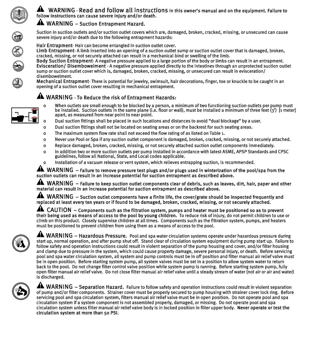
40 36


41 37
42 38
43 39

44 FOR FURTHER INFORMATION OR CONSUMER TECHNICAL SUPPORT, VISIT OUR WEBSITE AT Hayward is a registered trademark Hayward Industries, Inc. All other trademarks not owned by Hayward are the property of their respective owners. Hayward is not in any way affiliated with or endorsed by those third parties
OmniLogic. Automation and Chlorination. Installation Manual. Contents HLBASEAU
 092669 RevA OmniLogic Automation and Chlorination Installation Manual Contents Before You Begin...1 Overview...1 Mounting Equipment...4 Plumbing...6 Wiring...10 Preparing Pool/Spa Water...21 System Startup...23
Installation Manual for models
 Automation and Chlorination Installation Manual for models PL-PS-4 PL-PS-8 PL-PS-16 PL-PS-8-V PL-PS-16-V G LDLINE CON TROLS www.goldlinecontrols.com IMPORTANT SAFETY INSTRUCTIONS When using this electrical
Gunite & Fiberglass Pools
 Electrical Wiring The Pro Logic Control Center and PS-16 Expansion Unit require both high and low voltage connections. Low voltage connections will be made to actuators, sensors, remote keypad, etc. High
Automation and Chlorination. Installation Manual. for model PL-P-4 CON TROLS.
 Automation and Chlorination Installation Manual for model PL-P-4 G LDLINE CON TROLS www.goldlinecontrols.com IMPORTANT SAFETY INSTRUCTIONS When using this electrical equipment, basic safety precautions
Aqua Plus 16v. Automation and Chlorination. Installation Manual. Contents PL-PLUS-16V
 092456 RevD Aqua Plus 16v Automation and Chlorination \ Installation Manual Contents Introduction...2 Pool Chemistry...3 Installation...6 Configuration...24 System Startup...45 Warranty...50 PL-PLUS-16V
Aqua Logic LDLINE. Installation Manual for models AQ-LOGIC-PS-4 AQ-LOGIC-PS-8. Automation and Chlorination CONTROLS INC.
 Aqua Logic Automation and Chlorination Installation Manual for models AQ-LOGIC-PS-4 AQ-LOGIC-PS-8 G LDLINE CONTROLS INC. www.goldlinecontrols.com 888-921-7665 IMPORTANT SAFETY INSTRUCTIONS When using this
Aqua Plus. Installation Manual for model. Aqua Plus Programming Flow Chart. Automation and Chlorination AQL-PLUS AQL-PLUS-20 G CON TROLS
 Aqua Plus Programming Flow Chart denotes conditional items Aqua Plus Automation and Chlorination Aqua Plus only Aqua Plus only (actuator and remote display not included - order separately) Installation
Hayward. OnCommand. Installation Manual. Automation. for models ONCOM ONCOM-ACT ONCOM-RC ONCOM-ACT-RC.
 Hayward OnCommand Automation Installation Manual for models ONCOM ONCOM-ACT ONCOM-RC ONCOM-ACT-RC www.haywardnet.com IMPORTANT SAFETY INSTRUCTIONS When using this electrical equipment, basic safety precautions
VS Omni. Pool Automation Control. Installation Manual HL32950VVSP HL32900VSP HL26720VSP HL23520VSP HL23510VSP
 092680 RevB VS Omni Pool Automation Control Installation Manual Contents HL32950VVSP HL32900VSP HL26720VSP HL23520VSP HL23510VSP Before you Begin...3 Mounting...7 Plumbing...9 Wiring...10 Startup...22
Aqua Logic. Operation Manual. Automation and Chlorination AQL-P CON TROLS. for model
 Aqua Logic Automation and Chlorination (actuators, cell & remote display not included - order separately) Operation Manual for model AQL-P-4 G LDLINE CON TROLS www.goldlinecontrols.com 888-921-7665 IMPORTANT
Pro Logic. Automation and Chlorination. Operation Manual. Contents PL-PS-16-V
 092331D RevH Pro Logic Automation and Chlorination \ Operation Manual Contents Introduction...2 Operation...4 Pool Chemistry...43 Troubleshooting...48 Warranty...54 PL-PS-4 PL-PS-8 PL-PS-16 PL-PS-8-V PL-PS-16-V
Automation and Chlorination. Operation Manual. for models PL-PLUS PL-PLUS CON TROLS
 Automation and Chlorination Operation Manual for models PL-PLUS PL-PLUS-20 G LDLINE CON TROLS www.goldlinecontrols.com 888-921-7665 IMPORTANT SAFETY INSTRUCTIONS When using this electrical equipment, basic
Aqua Plus 16v. Operation Manual for model. Automation and Chlorination PL-PLUS-16V.
 Aqua Plus 16v Automation and Chlorination Operation Manual for model PL-PLUS-16V www.haywardnet.com IMPORTANT SAFETY INSTRUCTIONS When using this electrical equipment, basic safety precautions should always
Hayward ECOMMAND. Installation Manual. Automation.
 Hayward ECOMMAND Automation Installation Manual www.haywardnet.com IMPORTANT SAFETY INSTRUCTIONS When using this electrical equipment, basic safety precautions should always be followed, including the
Aqua Plus. Operation Manual for model G CON TROLS. Automation and Chlorination AQL-PLUS AQL-PLUS-20 TEST IDEAL RANGE ADJUSTMENT REQUIRED
 TEST IDEAL RANGE ADJUSTMENT REQUIRED Aqua Plus Automation and Chlorination Free Chlorine 1.0-3.0 ppm Turn output dial up to increase, down to decrease -OR- increase or decrease pump filtration time. ph
PRO LOGICTM. Automation and Chlorination. Operation Manual for models PL-PS-16-V CON TROLS
 PRO LOGICTM Automation and Chlorination Operation Manual for models PL-PS-4 PL-PS-8 PL-PS-16 PL-PS-8-V PL-PS-16-V G LDLINE CON TROLS www.goldlinecontrols.com 888-921-7665 IMPORTANT SAFETY INSTRUCTIONS
OmniHub. Pool Automation Control. Installation Manual HLOMNIHUB
 092711 RevA OmniHub Pool Automation Control Installation Manual Contents Before you Begin...3 Mounting...8 Plumbing...10 Wiring...11 Startup...23 Configuration...24 HLOMNIHUB Hayward Pool Products 620
Aqua Plus. Automation and Chlorination. Operation Manual PL-PLUS PL-PLUS-20
 092360D RevH Aqua Plus Automation and Chlorination \ Operation Manual Contents Introduction...2 Operation...4 Chemistry...32 Troubleshooting...37 Warranty...42 PL-PLUS PL-PLUS-20 Hayward Pool Products
Aqua Logic. Operation Manual. Automation and Chlorination AQL-PS-16-V for models CON TROLS
 Aqua Logic Automation and Chlorination (actuators, cell & remote display not included - order separately) Operation Manual AQL-PS-4 AQL-PS-8 AQL-PS-16 for models AQL-PS-8-V AQL-PS-16-V G LDLINE CON TROLS
Pro Logic. Operation Manual for models. Automation and Chlorination PL-PS-16-V TEST IDEAL RANGE ADJUSTMENT REQUIRED
 Quarterly Monthly Weekly TEST IDEAL RANGE ADJUSTMENT REQUIRED Free Chlorine 1.0-3.0 ppm ph 7.2-7.8 Alkalinity Salt 80-120 ppm Raise desired output % to increase, lower desired output % to decrease -OR-
OnCommand. Automation. Operation Manual ONCOM ONCOM-ACT ONCOM-RC ONCOM-ACT-RC ONCOM-POD2 ONCOM-ACT-POD2
 092442A RevC OnCommand Automation \ Operation Manual Contents Introduction...2 Operation...3 Troubleshooting...29 Warranty...34 ONCOM ONCOM-ACT ONCOM-RC ONCOM-ACT-RC ONCOM-POD2 ONCOM-ACT-POD2 Hayward Pool
ProLogic /AquaLogic. Consumer Troubleshooting Guide. CTSG-PL447a. Copyright 2016 Hayward Industries Inc.
 ProLogic /AquaLogic Consumer Troubleshooting Guide CTSG-PL447a Copyright 2016 Hayward Industries Inc. Safety Precautions Warning! High Voltage Electrocution Hazard Hazardous voltage can shock, burn, cause
TP WEM01 A Carrierr Côr Thermostat AC/HP Wi-Fir Thermostat Performance Series. Installation Guide
 TP WEM01 A Carrierr Côr Thermostat AC/HP Wi-Fir Thermostat Performance Series Installation Guide INTRODUCTION Welcome and from all of us at Carrier, thank you for purchasing your new Côr thermostat: the
Automation. All the control you ll need to create the ultimate pool experience.
 Automation All the control you ll need to create the ultimate pool experience. Hayward automates virtually everything, for a better backyard experience and more time to enjoy it. Hayward offers a line
OWNER S MANUAL. Vintage Signature Series models: AC750, AC1050, AC1100, AC1250, AC1500, AC1750. Proudly Made in the USA.
 OWNER S MANUAL Vintage Signature Series models: AC750, AC1050, AC1100, AC1250, AC1500, AC1750 Proudly Made in the USA support@aquacomfort.com 888-475-7443 Manufacturing High Quality, High Efficiency Heat
Owner s Manual RD432-0 Chemical Controller
 Owner s Manual RD432-0 Chemical Controller Table of Contents I. Introduction page 2 A. Water Chemistry page 2 B. Safety page 3 C. System Components page 4 D. Specifications page 7 E. Controller Panel Descriptions
Ozone Generator Systems
 PZ2-1 & PZ2-2 - Commercial and Residential Pools & Spas Ozone Generator Systems INSTALLATION GUIDE and OPERATION MANUAL T. O3 NATURAL TECHNOLOGY Reduces Chemical Usage, Improves Sanitation Produces Crystal
Sundance Spas SPA EQUIPMENT SYSTEM. Installation Instructions. P/N Rev. A
 Sundance Spas SPA EQUIPMENT SYSTEM Installation Instructions P/N 6530-456 Rev. A Contents Important Notices 1 Important Safety Instructions 2 Where to Place the Equipment System 3 Connecting Pipes Between
Wave Series. Installation and User Guide. PE950 Hand-Held Remote Transceiver PE650 Panel-Mounted Transceiver
 Wave Series PE950 Hand-Held Remote Transceiver PE650 Panel-Mounted Transceiver Intermatic, Inc. 7777 Winn Road Spring Grove, Illinois 60081-9698 www.intermatic.com Intermatic Customer Service: 815-675-7000
ADEMCO 4208SNF V-Plex Universal Class A Module INSTALLATION AND SETUP GUIDE
 K3179V2 2/11 Rev. A ADEMCO 4208SNF V-Plex Universal Class A Module INSTALLATION AND SETUP GUIDE FEATURES The ADEMCO 4208SNF Universal Class A Module can be used in either of two different applications.
M770 ph Controller Owner s Manual
 M770 ph Controller Owner s Manual Table of Contents I. Introduction page 2 A. Water Chemistry page 2 B. Safety page 3 C. System Components page 4 D. Specifications page 7 E. Controller Panel Descriptions
Ozone Generator Systems
 PZ2-4V - Commercial and Residential Pools & Spas Ozone Generator Systems INSTALLATION GUIDE and OPERATION MANUAL T. O3 NATURAL TECHNOLOGY Reduces Chemical Usage, Improves Sanitation Produces Crystal Clear
THE PUMP THEY NEED PLUS THE POOL CONTROL THEY WANT.
 THE PUMP THEY NEED PLUS THE POOL CONTROL THEY WANT. VS OMNI PUMPS WITH SMART POOL CONTROL ARE THE SIMPLEST WAY TO ADD TO POOLS AND SPAS. Energy-efficient VS Omni pumps offer smart control for up to four
IMPORTANT SAFETY INSTRUCTIONS READ AND FOLLOW ALL INSTRUCTIONS SAVE THESE INSTRUCTIONS
 Operating Manual MODEL RC554X AND 554230 ORP Digital Controller FEED ALERT ORP FLOW AUTO MODE SET LEVEL FEED TIME FLOW SWITCH ORP ORP OUTPUT POWER IMPORTANT SAFETY INSTRUCTIONS READ AND FOLLOW ALL INSTRUCTIONS
AquaRite. Troubleshooting Guide Residential. TSG-AQR159d. Copyright 2017 Hayward Industries Inc.
 AquaRite Troubleshooting Guide Residential TSG-AQR159d Copyright 2017 Hayward Industries Inc. Safety Precautions Warning! High Voltage Electrocution Hazard Hazardous voltage can shock, burn, cause serious
IMPORTANT SAFETY INSTRUCTIONS READ AND FOLLOW ALL INSTRUCTIONS SAVE THESE INSTRUCTIONS
 Operating Manual MODEL RC554P AND 554200 ph Digital Controller FEED ph FLOW ALERT AUTO MODE SET LEVEL FEED TIME ph CALIB FLOW SWITCH ph ph OUTPUT POWER IMPORTANT SAFETY INSTRUCTIONS READ AND FOLLOW ALL
PZ1, PZ3 & PZ6 Installation Guide
 PZ1, PZ3 & PZ6 Installation Guide PROZONE INTERNATIONAL, INC. Ozone Water Purification Systems INSTALLATION GUIDE Prozone PZ1, PZ3 and PZ6 Series Ozone Generator Systems SAFETY READ AND FOLLOW ALL INSTRUCTIONS.
Clear Comfort Residential Pool & Spa Sanitization System Installation, Operations & Maintenance Manual
 Clear Comfort Residential Pool & Spa Sanitization System Installation, Operations & Maintenance Manual IMPORTANT SAFETY INSTRUCTIONS For Further Assistance Contact Us: 303.872.4477 support@clearcomfort.com
Disclaimer. Trademarks. Copyright. Warranty
 1 Disclaimer Trademarks Copyright Control4 makes no representations or warranties with respect to any Control4 hardware, software, or the contents or use of this publication, and specifically disclaims
Quick Start Guide. For product manuals and further installation / operation procedures visit
 Quick Start Guide For product manuals and further installation / operation procedures visit www.aquacal.com Important Read This Guide Before Installing or Operating Heat Pump LTP0093 Rev 1 03/21/2014 Page
INSTALLATION INSTRUCTIONS
 INSTALLATION INSTRUCTIONS VARIABLE SPEED BOOSTER PUMP IMPORTANT SAFETY INSTRUCTIONS READ AND FOLLOW ALL INSTRUCTIONS SAVE THESE INSTRUCTIONS IMPORTANT SAFETY INFORMATION WARNING: RISK OF ELECTRICAL SHOCK
PZ2 Series Manual. PROZONE INTERNATIONAL, Inc. Ozone Water Purification Systems. INSTALLATION GUIDE and OPERATION MANUAL. Prozone PZ2 Series
 PZ2 Series Manual PROZONE INTERNATIONAL, Inc. Ozone Water Purification Systems INSTALLATION GUIDE and OPERATION MANUAL Prozone PZ2 Series Ozone Generator Systems SAFETY READ AND FOLLOW ALL INSTRUCTIONS.
OWNER S MANUAL. Models: AC110, AC125, AC150 made from 2003 through Proudly Made in the USA
 OWNER S MANUAL Models: AC110, AC125, AC150 made from 2003 through 2010 Proudly Made in the USA support@aquacomfort.com www.aquacomfort.com/service-and-support/ (888) 475-7443 Manufacturing High Quality,
M790 ph/orp Controller. Owner s Manual
 M790 ph/orp Controller Owner s Manual Table of Contents I. Introduction page 2 A. Water Chemistry page 2 B. Safety page 3 C. System Components page 4 D. Specifications page 7 E. Controller Panel Descriptions
Next Generation Corona Discharge Installation & Operation Manual
 Next Generation Corona Discharge Installation & Operation Manual 4-2319-01 Rev.A IMPORTANT SAFETY INSTRUCTIONS READ & FOLLOW ALL INSTRUCTIONS Read this manual completely before attempting installation.
OWNER S MANUAL. Vintage Classic HEAT COOL models. Proudly Made in the USA
 OWNER S MANUAL Vintage Classic HEAT COOL models Proudly Made in the USA support@aquacomfort.com www.aquacomfort.com/service-and-support 888-475-7443 Manufacturing High Quality, High Efficiency Heat Pump
IMPORTANT SAFETY INFORMATION! WARNING ALWAYS keep electric cords, home furnishings, drapes, clothing, papers, or other combustibles at least 3 feet (0
 Electric Fireplace Factory Model: EF-30D CONSUMER SAFETY INFORMATION Read this manual before installing and operating this appliance Failure to follow these instructions may result in electric shock, fire
WARNING. H Rev -
 OWNER'S Manual English FRANÇAIS H0367100 Rev - WARNING FOR YOUR SAFETY - For anything other than the routine cleaning and maintenance described in this manual, this product must be serviced by a contractor
Homeowner s Installation Instructions & Operating Manual
 Homeowner s Installation Instructions & Operating Manual ELECTRIC HEATER WITH REMOTE CONTROL Model: EF42D, EF43D, EF44D, EF45D READ AND SAVE THESE INSTRUCTIONS READ CAREFULLY BEFORE ATTEMPTING TO ASSEMBLE,
Homeowner s Installation Instructions & Operating Manual
 Wall Mounted Electric Fireplace Homeowner s Installation Instructions & Operating Manual Model: EF67B Series Used With Listed Front Facia Only: MT67C01 Black flat glass MT67C02 Black curved glass FOR YOUR
Caution: To maintain compliance with the RF exposure guidelines, place the unit at least 20cm from nearby persons.
 Installation Guide: for the Warmup Tempo Digital Programmable Thermostat The world s best-selling floor heating brand Introduction The Tempo thermostat is designed to aid in the comfort of your home by
SYSTEM ENHANCEMENT MODULE
 SYSTEM ENHANCEMENT MODULE DSC PowerSeries INSTALLATION GUIDE INSTALL WIZARD AVAILABLE AT ALARM.COM/SEMPOWERSERIES OVERVIEW The System Enhancement Module (SEM) can be used with DSC PowerSeries PC1616, PC1832,
Pet Immune SAW PIR Motion Sensor
 PET Immune SAW PIR Motion Sensors Installation Sheet Description This is the Installation Sheet for SAW PIR and PET Immune Motion Sensors. See Table 1. Table 1: Motion Sensors 60-807-95R 60-807-01-95R
Yale Real Living Touchscreen Deadbolt Installation and Programming Instructions
 Yale Real Living Touchscreen Deadbolt Installation and Programming Instructions x3 #8-32 x 5/16" Machine screws x4 #7 wood & #8-32 machine x 20mm Combination screws x2 M6x47mm Long through bolt 1 Preparing
DRAFT INSTALLATION INSTRUCTIONS. Solid-State Series !! NOTE!! Covers the following models: Refer to INSERT for additional information
 INSTALLATION INSTRUCTIONS Solid-State Series!! NOTE!! Covers the following models: " CS6100 - CS7100 " CS6200 - CS9200 " CS6220 - CS9220 " CS6230 - CS9230 " CS6500 - CS7500 " CS6330 - CS9300 " CS9400 -
Installation Instructions
 Installation Instructions S E C U R I T Y S Y S T E M Please refer to the System Installation Manual for information on limitations regarding product use and function and information on the limitations
HP Power Distribution Unit with Power Monitoring (Models S124 and S132) User Guide
 User Guide") HP Power Distribution Unit with Power Monitoring (Models S124 and S132) User Guide March 2006 (First Edition) Part Number 413611-001 Copyright 2006 Hewlett-Packard Development Company, L.P. The information
HP Power Distribution Unit with Power Monitoring (Models S124 and S132) User Guide March 2006 (First Edition) Part Number 413611-001 Copyright 2006 Hewlett-Packard Development Company, L.P. The information
EcoMaster - Residential Pools up to 40,000 Gallons
 - Residential Pools up to 40,000 Gallons INSTALLATION/ OPERATION GUIDE Reduces Chemical Usage, Improves Sanitation Produces Crystal Clear Water Copyright 2013 Prozone Water Products: 3004 11 th Ave. -
Yale Real Living Key Free Push Button Deadbolt B1L Installation and Programming Instructions
 Yale Real Living Key Free Push Button Deadbolt B1L Installation and Programming Instructions Before you begin DOWNLOAD THE BILT APP for step-by-step installation instructions & to register your product
Homeowner s Installation Instructions & Operating Manual
 Homeowner s Installation Instructions & Operating Manual ELECTRIC HEATER WITH REMOTE CONTROL Model: EF42D, EF43D, EF44D, EF45D READ AND SAVE THESE INSTRUCTIONS READ CAREFULLY BEFORE ATTEMPTING TO ASSEMBLE,
SPA HEATER INSTALLATION, OPERATION AND MAINTENANCE
 SPA INSTALLATION, OPERATION AND MAINTENANCE MODELS: ST SERIES 5.5 & 11kW 240V SINGLE PHASE BEFORE YOU BEGIN CHECK ALL ELECTRICAL CONNECTIONS TO ALL COMPONENTS WITHIN THE FOR TIGHTNESS. CONNECTIONS CAN
GARAGE HEATER WITH REMOTE INSTRUCTION MANUAL MODEL: HA24-100E HA24-150E. Figure 1
 GARAGE HEATER WITH REMOTE INSTRUCTION MANUAL MODEL: HA24-100E HA24-150E Figure 1 PET OWNERS WARNING: Health warning for some small pets, including birds, as they are extremely sensitive to the fumes produced
LC-151 Dual-Tech Motion Sensor (Single PIR & Microwave) with adjustable Pet Immunity INSTALLATION INSTRUCTIONS & USER MANUAL P/N: ver.
 with adjustable Pet Immunity INSTALLATION INSTRUCTIONS & USER MANUAL P/N: ver.") LC-151 Dual-Tech Motion Sensor (Single PIR & Microwave) with adjustable Pet Immunity INSTALLATION INSTRUCTIONS & USER MANUAL P/N: 7131720 ver.b 1 1 General... 3 2 Features... 3 3 Assembly description...
LC-151 Dual-Tech Motion Sensor (Single PIR & Microwave) with adjustable Pet Immunity INSTALLATION INSTRUCTIONS & USER MANUAL P/N: 7131720 ver.b 1 1 General... 3 2 Features... 3 3 Assembly description...
Heat Transfer Products, Inc. 120 Braley Road East Freetown, MA The first totally integrated multiple boiler management control.
 Heat Transfer Products, Inc. 120 Braley Road East Freetown, MA 02717 The first totally integrated multiple boiler management control. USING THIS MANUAL USING THIS MANUAL A. INSTALLATION SEQUENCE Follow
Yale Real Living Assure Lock Push Button Deadbolt Installation and Programming Instructions (YRD216)
") Yale Real Living Assure Lock Push Button Deadbolt Installation and Programming Instructions (YRD216) Optional Network Module x3 #8-32 x 5/16" Machine screws x4 #7 wood & #8-32 machine x 20mm Combination
Yale Real Living Assure Lock Push Button Deadbolt Installation and Programming Instructions (YRD216) Optional Network Module x3 #8-32 x 5/16" Machine screws x4 #7 wood & #8-32 machine x 20mm Combination
QUICK START GUIDE. Lono, LLC 686 East 110 South, Suite 102 American Fork, UT 84003
 QUICK START GUIDE Lono, LLC 686 East 110 South, Suite 102 American Fork, UT 84003 Welcome. This guide will help you install your Lono controller. For additional information, check out our installation
Powerley Thermostat. Installation & Operation Guide
 Powerley Thermostat Installation & Operation Guide i Welcome! After a quick installation, your new Powerley Thermostat will allow you to monitor and control your HVAC system from anywhere in the world.
MODEL ORP/pH Digital Controller
 MODEL 554000 ORP/pH Digital Controller Operating Manual Rola-Chem Digital Controller PN 554102 6/01/2012 Page: 1 of 20 QUICK START REFERENCE Use this section for reference - please read all safety instructions
Owner s Manual PRINTED IN CANADA 05/2009
 Owner s Manual PRINTED IN CANADA 05/2009 Table of contents Introduction 2 General Safety Instructions 4 Installation Instructions Location 6 Water piping 7 Electrical 7 Bonding 8 Bonding and plumbing
CAT Water Quality Controller. Owner s Manual. Contents CAT-5500
 092601 RevC CAT 5500 Water Quality Controller \ Owner s Manual Contents Introduction...2 Installation...4 Pool Chemistry...7 Configuration...7 System Maintenance...31 Network Communications...32 Troubleshooting...36
IDP-Zone-6 Six Zone Interface Module
 INSTALLATION AND MAINTENANCE INSTRUCTIONS IDP-Zone-6 Six Zone Interface Module BEFORE INSTALLING If the modules will be installed in an existing operational system, inform the operator and local authority
2017 EcoFactor, Inc.
 User Guide 2017 EcoFactor, Inc. Introduction The thermostat supports up to 2 stages of heating and 2 stages of cooling for conventional systems, and 2 stages of heating/ cooling for heat pumps, with and
Table of Contents 1. OVERVIEW SYSTEM LAYOUT SPECIFICATIONS FUNCTION... 11
 Table of Contents 1. OVERVIEW... 3 2. SYSTEM LAYOUT... 4 3. SPECIFICATIONS... 8 3.1 SYSTEM COMPONENTS...9 3.2 PLC INPUTS AND OUTPUTS...9 3.3 FUNCTION KEYS...10 3.4 DEFAULT SET POINTS AND TIMERS...10 4.
INSTALLATION MANUAL ESM9+ / ESM11+ / ESM15+
 INSTALLATION MANUAL ESM9+ / ESM+ / ESM5+ THANK YOU Thank you for choosing a water softener from EcoWater. With over 80 years experience we have manufactured your new water softener from quality corrosion
HydroRite UVO 3. Troubleshooting Guide Residential. TSG-UVO158a. Copyright 2015 Hayward Industries Inc.
 HydroRite UVO 3 Troubleshooting Guide Residential TSG-UVO158a Copyright 2015 Hayward Industries Inc. Safety Precautions Warning! When installing and using this electrical equipment, basic safety precautions
Owner s Manual for Swimming Pool Heat Pump
 Owner s Manual for Swimming Pool Heat Pump FC Series nirvanahp.com CONTENTS How it works 1 Installation 2 3 Settings 4 5 6 7 Start-up 8 Winterizing 9 Maintenance 10 Troubleshooting 11 12 13 Warranty 14
Homeowner s Installation Instructions & Operating Manual
 Homeowner s Installation Instructions & Operating Manual ELECTRIC HEATER WITH REMOTE CONTROL Model: GI-32-ZC IS-36-ZC, IS-42-ZC Insert surrounds READ AND SAVE THESE INSTRUCTIONS READ CAREFULLY BEFORE ATTEMPTING
IMPORTANT SAFETY INSTRUCTIONS READ AND FOLLOW ALL INSTRUCTIONS SAVE THESE INSTRUCTIONS
 Operating Manual MODELS RC554XP AND 554000 ORP/pH Digital Controller FEED ph ALERT FEED ORP ALERT F LOW ph MODE AUTO FEED ONCE SET LEVEL FEED TIME HI LOW ph CALIB ORP ph ORP IMPORTANT SAFETY INSTRUCTIONS
EcoMaster - Residential Pools up to 40,000 Gallons
 - Residential Pools up to 40,000 Gallons INSTALLATION/ OPERATION GUIDE Reduces Chemical Usage, Improves Sanitation Produces Crystal Clear Water PROZONE Copyright 2018 Prozone Water Products: 3004 11 th
COMBINATION ELECTRIC FIREPLACE/HEATER Model #FP23-1A-AKM
 LOT NUMBER: DATE PURCHASED: / / USE AND CARE GUIDE COMBINATION ELECTRIC FIREPLACE/HEATER Model #FP23-1A-AKM If you have any questions regarding the use of this unit, or find that your fireplace/heater
SEE DISCLAIMER ON REVERSE
 BOLTEK CORPORATION Lightning Detection GSM-1 Text Message Notification for EFM-100C Electric Field Monitor User Guide SEE DISCLAIMER ON REVERSE BOLTEK LIGHTNING DETECTION GSM-1 Text Message Alert Dialer
CONTENTS CONSIDERATIONS. General Plumbing Component Connection ILLUSTRATION. Control System CONFIGURATION. Voltage Verification CONNECTION
 AIR SERIES SYSTEM INSTALLATION MANUAL CONTENTS CONSIDERATIONS General Plumbing Component Connection 2 2 2 ILLUSTRATION Control System 3 CONFIGURATION Voltage Verification 4 CONNECTION Component Connection
Table of Contents. What to Expect with. Mounting Options. Tools Needed
 www.hunterfan.com Table of Contents What to Expect with Your Installation Congratulations on purchasing your new Hunter ceiling fan! It will provide comfort and performance in your home or office for many
Installation in Standard & Variable Speed Indoor Air Handlers IMPORTANT
 H6HK Series Electric Heater Kit INSTALLATION INSTRUCTIONS Installation in Standard & Variable Speed Indoor Air Handlers IMPORTANT These instructions are primarily intended to assist qualified individuals
Installation and Operation Manual. ACF-18 Automatic Chlorinating Feeder
 Installation and Operation Manual ACF-18 Automatic Chlorinating Feeder Operating Specifications Inlet Flow: 1.0-1.5 gpm Outlet Flow: = Inlet Flow Inlet Pressure: 10-45 psi Maximum Output: 26 lbs. of Available
I NTEGRATED S ENSOR S UITE WITH F AN-ASPIRATED R ADIATION SHIELD ADDENDUM, REV B. For Vantage Pro and Vantage Pro Plus
 I NTEGRATED S ENSOR S UITE WITH F AN-ASPIRATED R ADIATION SHIELD ADDENDUM, REV B For Vantage Pro and Vantage Pro Plus The Vantage Pro Integrated Sensor Suite (ISS) with the Fan-Aspirated Radiation Shield
Heat Pumps. English. Models: M1, M2, M3, M4, M5. User Manual
 English User Manual Heat Pumps Models: M1, M2, M3, M4, M5 For product manuals and further installation operation procedure contact poolcalor@yahoo.com.br S E C T I O N 1 - G E N E R A L I N F O R M AT
Wireless High Bay Sensor (WHS100) Installation Instructions
 Installation Instructions") Installation Instructions The Daintree Networks WHS100 Wireless High Bay Sensor is a line powered control component within the ControlScope wireless building controls platform. It enables wireless control
Installation Instructions The Daintree Networks WHS100 Wireless High Bay Sensor is a line powered control component within the ControlScope wireless building controls platform. It enables wireless control
EW 40 Wireless Fan Control
 Installation & Operating Manual EW 40 Wireless Fan Control USA CAN Product Information... Chapters 1 + 2 Mechanical Installation... Chapter 3 Electrical Installation... Chapter 4 Start Up and Configuration...
M820 ph/dual ORP Controller. Owner s Manual
 M820 ph/dual ORP Controller Owner s Manual Table of Contents I. Introduction page 2 A. Water Chemistry page 2 B. Safety page 3 C. System Components page 4 D. Specifications page 7 E. Controller Panel Descriptions
KONICA MINOLTA GP-502 OPERATION MANUAL
 KONICA MINOLTA GP-502 OPERATION MANUAL Rev 1.0 February 2012 Table of Contents 1. Safety 2. Overview 2.1 Features & Benefits of GP-502 2.2 Ellipse Binding Elements 2.3 User Interface & Feature Locations
Square D Clipsal Outdoor Light-Level Sensor
 Square D Clipsal Outdoor Light-Level Sensor SLC5031PEWP for Use with C-Bus Wired Networks Instruction Bulletin Retain for future use. Square D Clipsal Outdoor Light-Level Sensor 63249-420-231A3 Instruction
Ultrasonic Wall Switch Occupancy Sensor Single Circuit
 Instruction Bulletin 63249-420-414A1 02/2014 Ultrasonic Wall Switch Occupancy Sensor Single Circuit Commercial Grade with Ground, Single and Multi Location Switching SLSUWS1277C and SLSUWS3277C Retain
RGR150 USER S MANUAL. Wireless Rain Gauge with Thermometer and Clock
 RGR150 manual-final-091908:layout 1 9/19/08 8:59 AM Page 1 RGR150 USER S MANUAL Wireless Rain Gauge with Thermometer and Clock INTRODUCTION Thank you for selecting this Wireless Rain Gauge. This device
Closing procedures for in-ground pools
 Closing procedures for in-ground pools Note: Carefully read this entire document before proceeding with the closure of your pool. In order to avoid unpleasant surprises, please check with your insurance
SLATE. Base Module INSTALLATION INSTRUCTIONS R8001A1001
 SLATE Base Module R8001A1001 INSTALLATION INSTRUCTIONS Scan for more information Application SLATE brings configurable safety and programmable logic together into one single platform. The platform can
Ozone plus UV Sanitation System Installation & Operations Manual
 Ozone plus UV Sanitation System Installation & Operations Manual 3580 Sueldo Street, San Luis Obispo, CA 93401 800.676.1335 o3info@delozone.com www.delozone.com 4-2305-01 Rev.B TABLE OF CONTENTS SECTION
CONTENTS DESCRIPTION UNPACKING DIMENSIONS
 INSTALLATION INSTRUCTIONS Ventilating Fan ModelNo.FV-08VRE CONTENTS GENERAL SAFETY INFORMATION DESCRIPTION UNPACKING SUPPLIED ACCESSORIES DIMENSIONS WIRING DIAGRAM INSTALLATION (BETWEEN JOISTS MOUNTING)
Table of Contents What to Expect with. Tools Needed. Mounting Options. Wiring. Switch Housing.
 Table of Contents Congratulations on purchasing your new Hunter ceiling fan! It will provide comfort and performance in your home or office for many years. This installation and operation manual contains
HAYWARD POOL PRODUCTS, INC. 620 Division Street Elizabeth, NJ Tel:
 IS270T-05 Rev. B OWNER S MANUAL INSTALLATION, OPERATION & PARTS MODEL S270T PRO SERIES HIGH-RATE SAND FILTER Basic safety precautions should always be followed, including the following: Failure to follow