INSTALLATION, OPERATION AND MAINTENANCE MANUAL FOR ELECTRIC DEIONIZED / RO WATER HEATER
|
|
|
- Melina Shepherd
- 5 years ago
- Views:
Transcription


1 INSTALLATION, OPERATION AND MAINTENANCE MANUAL FOR ELECTRIC DEIONIZED / RO WATER HEATER ELECTRIC HEATER COMPANY BASE MODEL HD 2015 Edition UM ANSI/NSF5
2 HUBBELL ELECTRIC HEATER COMPANY 45 SEYMOUR STREET P.O. BOX 288 STRATFORD, CT PHONE: (203) FAX: (203) INTERNET: -- IMPORTANT -- Always reference the full model number and serial number when calling the factory. WARNING / CAUTION 1. Tank is to be completely filled with water and all air is to be vented before energizing. 2. Due to the rigors of transportation, all connections should be checked for tightness before heater is placed in operation. 3. Safety relief valve must be installed in tapping provided. 4. The refractory material used in heating elements may absorb some moisture during transit, periods of storage, or when subjected to a humid environment. This moisture absorption results in a cold insulation resistance of less than twenty (20) megohms. If this heater has been subjected to the above condition, each heating element must be checked for insulation resistance before energizing. Contact the factory for a replacement element. 5. KEEP AWAY FROM LIVE ELECTRICAL CIRCUITS. Do not perform any maintenance, make any adjustments, or replace any components inside the control panel with the high voltage power supply turned on. Under certain circumstances, dangerous potentials may exist even when the power supply is off. To avoid casualties, always turn the power supply safety switch to off, turn the charge or ground the circuit before performing any maintenance or adjustment procedure. 6. The unit is designed to operate at pressure not more than 150 psi. 7. Generalized instructions and procedures cannot anticipate all situations. For this reason, only qualified installers should perform the installations. A qualified installer is a person who has licensed training and a working knowledge of the applicable codes, tools, equipment, and methods necessary for safe installation of an electric resistance water heater. If questions regarding installation arise, check your local plumbing and electrical inspectors for proper procedures and codes. If you cannot obtain the required information, contact the company. 2
3 TABLE OF CONTENTS SECTION TITLE PAGE No. I GENERAL DESCRIPTION AND CONSTRUCTION 4 II INSTALLATION AND START-UP 8 III SCHEDULED MAINTENANCE AND OPERATION 20 IV TROUBLESHOOTING 23 V SERVICING AND REPLACEMENT OF PARTS 28 VI SERVICE PARTS LIST 32 VII TORQUE VALUES 34 VIII WARRANTY INFORMATION 35 3
4 SECTION I - GENERAL DESCRIPTION AND CONSTRUCTION GENERAL DESCRIPTION This book describes a packaged electric water heater designed for use in deionized (DI) or reverse osmosis (RO) water applications. The complete assembly consists of the storage tank, immersion electric heating element(s), electronic control module, safety relief valve, magnetic contactor(s), and any other required electrical operating control. Optional equipment may be supplied with your unit. Please consult the product drawing supplied with the unit for details specific to your assembly. The unit is factory assembled, insulated, jacketed, wired, tested, and ready for electrical and plumbing service connections. Model Storage Capacity (gallons) kw 60 F Rise (GPH) 80 F Rise (GPH) 100 F Rise (GPH) CAPACITY 120 F Rise (GPH) Model Storage Capacity (gallons) kw 60 F Rise (GPH) 80 F Rise (GPH) 100 F Rise (GPH) 120 F Rise (GPH) HD HD HD HD HD HD HD HD HD HD HD HD HD HD HD HD HD HD HD HD HD HD HD HD HD HD HD HD HD HD HD HD HD HD HD HD HD HD HD HD HD HD HD HD HD HD HD HD HD HD HD HD HD If the required temperature rise is not listed above, the following formula may be used to determine the maximum flow rate: To determine power (kw) requirement GPM F ΔT = kw To determine temperature rise kw GPM = F ΔT To determine flow rate kw FΔT = GPM 4
5 5
6 6
.")


, composed of 316L stainless steel sheathed elements that are fitted into a 316L stainless steel")
7 CONSTRUCTION TANK The storage tank is designed, manufactured, and stamped in accordance with ASME Section VIII Division 1. The tank is constructed of type 316L stainless steel and fabricated by all welded construction and is designed for a maximum allowable working pressure of 150 psi (225 psi test pressure). As an option, the rear head may be a bolted flange connection that can be removed to facilitate internal inspection and cleaning of interior tank surfaces. TANK CONNECTIONS The heater is supplied with separate connections for the cold inlet and the hot water outlet. Water entering the cold water inlet and leaving through the hot water outlet is evenly circulated by means of a diffuser within the tank. A ¾-inch FNPT connection is provided for mounting a combination safety temperature and pressure relief valve. An overflow line should be utilized from the relief valve outlet to a floor drain. See drawing for locations and sizes. HEATING ELEMENT The water heater is supplied with an electric immersion heating element assembly(s), composed of 316L stainless steel sheathed elements that are fitted into a 316L stainless steel 1½-12UNF screw plug with 1-7/8 hex. The element wetted surfaces are passivated and electropolished. Each assembly is threaded into the tank and sealed with #220 Viton o-ring gaskets. See drawing for voltage and power ratings. MAGNETIC CONTACTOR The definite purpose magnetic contactor(s) is a heavy-duty resistive load type. The contactor supplies power to the heating element(s) based on the resistive load (non-inductive) of the heater only when the relay on the control board is closed, thereby pulling in the contacts until the desired temperature is reached. At this point, the contacts will drop out, which in turn disconnects power from the elements. Units with two contactors will turn on and off in stages. CONTROL BOARD AND DISPLAY The control board supplies all the necessary functions for heater operation. These include control temperature, hilimit cut-out, low water detection, and leak detection. LOW VOLTAGE CONTROL TRANSFORMER A control circuit transformer is supplied with all models rated greater than 240-volts. This component is used to step down the primary power supply (600, 480, 440, 415, 380, or 277) to 208/240- volts for safety when working with control circuits. POWER CIRCUIT BREAKERS When required by code, a magnetic power circuit breaker is supplied for circuit overload protection. The circuit breaker can be reset in the event of a current overload. OUTER SHELL, INSULATION, AND SUPPORTS The tank is encapsulated in high efficiency CFC/HCFC free closed cell foam insulation meeting the requirements for UL 94 HF-1 rating. The protective shell is constructed of type 304 brushed stainless steel. NSF approved adjustable plastic legs are provided for support. LOW WATER CUTOUT A float type 316L stainless steel low water cutout is included for low water detection. 7


8 OPTIONAL EQUIPMENT Slide Brackets Available for the HD6 Model only, these brackets allow for mounting the water heater under a counter. See slide bracket diagram on page 9 for details. Legs In lieu of the standard black plastic legs, optional adjustable legs are available in stainless steel, die-cast nickel plated, and floor mount stainless steel. All optional legs are adjustable height type. Floor Mount Nickel Plated Stainless Steel Alternate Voltage Other voltages are available, including 277V single-phase, and 380V, 415V, and 440V threephase. Consult the factory for details. XB1 Expansion Board An optional expansion board to the control board can be used to for additional circuit firing when more than two circuits are required and/or as an auxiliary high or low temperature alarm/relay. On models with three contactors the XB1 is supplied as standard. Remote Alarm Plug Adapter An optional plug adapter is available to provide a remote fault alarm signal through the J4 connector on the control board. See page 11 for installation details. 24-Volt Heater Interlock Adapter An optional plug adapter is available to interlock the heater via a 24-volt signal through the J1 connector on the control board. See page 11 for installation details. (Only available with r23 or later software). Protective Shrouds An optional durable protective plastic shroud is available to prevent damage to the heater due to water intrusion. The cover fits snugly over the entire heater and can be easily removed for cleaning and service. SECTION II INSTALLATION AND START-UP WARNING / CAUTION DO NOT TURN ON THE ELECTRIC POWER SUPPLY to this equipment until heater is completely filled with water and all air has been released. If the heater is NOT filled with water when the power is turned on, the heating elements will burn out. For protection against excessive pressures and temperatures, local codes require the installation of a temperature-and-pressure (T&P) relief valve certified by a nationally recognized laboratory that maintains periodic inspection of production of listed equipment of materials, as meeting the requirements for Relief Valves and Automatic Gas Shutoff for Hot Water Supply Systems. ANSI Z THE CUSTOMER IS RESPONSIBLE TO PROTECT PROPERTY AND PERSONNEL FROM HARM WHEN THE VALVE FUNCTIONS. All water heaters have a risk of leakage at some unpredictable time. IT IS THE CUSTOMER'S RESPONSIBILITY TO PROVIDE A CATCH PAN OR OTHER ADEQUATE MEANS, SO THAT THE RESULTANT FLOW OF WATER WILL NOT DAMAGE FURNISHINGS OR PROPERTY. Installation or service of this unit requires ability equal to that of a licensed tradesman in the field. 8

9 The installation must conform to these instructions and any local authority having jurisdiction. Grounding and electrical wiring connected to the unit must also conform to the latest version of the National Electric Code NFPA-70. WATER HEATER PLACEMENT 1. Place the heater on a solid, level foundation in a clean, dry location. 2. The water heater should be protected from freezing and waterlines insulated to reduce energy and water waste. 3. Leave a minimum of 18 clearance for element withdrawal and control access. 4. Do not install in an area where flammable liquids or combustible vapors are present. SLIDE BRACKETS FOR HANGING SUPPORT MOUNTING 1. Weld slide rails to bottom of table. Spacing should be 17 for HD6 models up to 18kW and 22 for HD6 models 24 to 58.5kW. HD16 models are not designed for use with slide brackets. 2. Attach slide bracket angles to heater with #8 sheet metal screws. It will be necessary to drill 1/8 holes into heater jacket for screw pilot holes. 3. Slide heater onto slide rails under table. PIPING INSTALLATION See Diagrams 1. Connect the cold water inlet and hot water outlet to the appropriate connections as shown; refer to the specifications for location and sizes. 2. Install the combination temperature and pressure safety relief valve in the tapping provided. Note that this is required by law for safety considerations. Install into provided tapping Manual Release Lever Temperature Probe Outlet to floor drain 3. Install a relief valve overflow pipe to a nearby floor drain. NOTE: Relief valve discharge piping limitations: a. Termination to be plain end (no threads) and 6-inches above the drain. b. Maximum 30-feet. c. Maximum four (4) elbows. d. No reduction in line size. e. No valve of any type to be installed between the relief valve and tank or in the drain line. FILLING THE HEATER 1. Open the valve to the cold water inlet and allow the heater and piping system to completely fill, as indicated by a steady flow of water through the process outlet. NOTE: Flush the tank at full flow for 10 minutes prior to putting into service. ELECTRICAL INSTALLATION 1. Enter the base through the factory cut KO s with properly sized feeder leads, See Wiring Chart. Single-phase installations require two (2) leads. All Hubbell 3-phase heaters are intended for use with a 3-wire delta system plus ground. No neutral is 9


 and Common (C) and the LED will flash green.")
 and C for low temperature alarm. A red LED indicates an error.")
 Power Wire (Common, White) (JX5 L2)Power Wire (Black) (JX5) (4) Connections for Additional Circuit Firing (JX2) Low Temp.")

10 required. For a 4-wire plus ground system, install 3 legs of power plus the ground and terminate the neutral leg. 2. Install these power leads into the box lugs on the power distribution block or magnetic contactor, as required. 3. Connect incoming ground wire to ground lug supplied. 4. Check for proper grounding. 5. All other electrical connections are made at the factory; therefore, no other electrical connections are necessary. 6. Check all connections, including factory connections, for tightness. OPTIONAL XB1 EXPANSION BOARD (used for temperature alarm / interlock) 1. If desired, the XB1 can be used as an alarm relay or a temperature interlock at a setpoint other than the water temperature setpoint on the water heater. 2. If the XB1 is not factory installed, mount the XB1 to the control panel and connect the XB1 to the T1000 control board with the factory supplied cable between JX4 on the XB1 and J1 and J4 on the T1000 and connect the ground between JX6 on the XB1 and J8 on the T Make connections as required to the relay terminal block. When the temperature drops below the XB1 setpoint the relay is open between Normally Open (NO) and Common (C) and the LED will flash green. When the temperature is above the XB1 setpoint the relay is closed between NO and C and the LED will be solid green. Use NO and C for low temperature interlock or high temperature alarm. Use Normally Closed (NC) and C for low temperature alarm. A red LED indicates an error. Note: Alarm Rating (resistive): Max.: 120VAC 24VDC (JX5 L1) Power Wire (Common, White) (JX5 L2)Power Wire (Black) (JX5) (4) Connections for Additional Circuit Firing (JX2) Low Temp. Relay Terminal Block Note: Once the XB1 is connected to the T1000 control board, an additional menu option will be available to set the low temperature setpoint. See Section III. FOR REMOTE ON/OFF CONTROL To remotely control the On / Off operation of the heater, it is recommended that a DPST switch or relay (by others) be used to break both power legs (white and black wires) connected to the top two terminals of the J5 connector on the control board. See diagram at right. Use a NC (Normally Closed) relay to turn the heater ON when energizing the relay coil or to turn the heater OFF when de-energizing the relay coil. Use a NO (Normally Open) relay to turn the heater OFF when energizing the relay coil or to turn the heater ON when de-energizing the relay coil. (JX6) Ground (JX4) Connection to T1000 (JX3) To be used as T1000 J1 Connection (JX1) To be used as T1000 J4 Connection LED 10
. 2.")
 Max. Switching Power: 60W, 62.")
11 OPTIONAL REMOTE ALARM CONTACTS 1. If desired, the control board can be wired to a remote alarm to indicate a reset fault condition. These fault conditions include over-temperature, no probe, and low water (when the configuration is set to manual reset). 2. This alarm can be wired to the J4 connector on the control board as shown below. To facilitate this installation, an optional adapter, Hubbell P/N PLUG ADAPTER J4, can be purchased to provide wire connections. J4 Connector Note: Rating (resistive) Max. Switching Power: 60W, 62.5VA Max. Switching Voltage: 220VDC, 250VAC Max. Switching Current: 2A Max. Carrying Current: 3A Common PLUG ADAPTER J4 (NO) (NC) Note: That when the XB1 expansion board is used, the J4 PLUG ADAPTER should plug into the JX1 connection on the XB1. OPTIONAL FIELD CONVERSION FROM SINGLE TO THREE PHASE OR THREE TO SINGLE PHASE (HD6 and HD16 models in 6, 7, and 9 kw and 208 and 240 volts only) 1. Find the appropriate diagram for the unit to be converted in the following chart titled Wiring Chart. 2. Re-wire the unit according to the diagram. NOTE: The wire to be used for internal wiring must conform to SEW-2 or PTFE (200 C) and must match the wire size currently in use. Contact the factory for assistance if required. 3. Contact the factory for correct labels. The factory will need the serial number for proper identification. OPTIONAL 24-VOLT HEATER INTERLOCK ADAPTER 1. If desired, the heater can be wired to operate only when supplied with a 24-volt signal through the heater interlock adapter. When no 24-volt signal is supplied through the heater interlock adapter the heater is interlocked and will not energize. When interlocked the display will show HLd. The heater will resume normal operation when a 24-volt signal is re-applied through the heater interlock adapter. 2. To utilize this feature, plug the 24-volt heater interlock adapter into terminal J1 of the T1000 control board (note: if the XB1 expansion board is used, plug the adapter into terminal JX3 of the XB1) and verify that the configuration is set to H on, see the controller operation section for further detail. The signal can be either AC or DC. However, if a DC signal is utilized and the interlock feature does not operate, switch the two 24-volt supply wires at the heater interlock adapter. J1 To J1 To 24-Volt Signal FINAL CHECKS 1. Check all connections for tightness. 2. Ensure that all the above steps are completed. 3. Remove the protective outer plastic covering from the sheet metal shell. 4. After the water is heated for the first time, monitor the water temperature as described in Section III, Annual Inspection. 11
12 kw Volt Ph Unit Amp Draw Branch Amp Draw Phase- Phase Resistance (Ohms) Wiring Chart Min. Feed Breaker or Fuse Size Internal Power Wire Size Element Jumper Wire Size Copper Conduit Power Feed Size Wire Size Diagram N/A 14 ½" 1(NT)-HD N/A 14 ½" 1(NT)-HD N/A 12 ½" 1(NT)-HD ½" 1(NT)-HD N/A 10 ½" 1(NT)-HD N/A 12 ½" 1(NT)-HD N/A 12 ½" 1(WT)-HD N/A 14 ½" 1(WT)-HD N/A 10 ½" 1(NT)-HD N/A 10 ½" 1(NT)-HD N/A 12 ½" 1(WT)-HD N/A 14 ½" 1(WT)-HD ½" 4-HD ½" 10(NT)-HD ½" 4-HD ½" 10(NT)-HD ½" 10(WT)-HD ½" 10(WT)-HD ½" 14-HD ½" 4-HD ½" 10(NT)-HD ½" 4-HD ½" 10(NT)-HD ½" 10(WT)-HD ½" 10(WT)-HD ½" 14-HD ¾" 4-HD ½" 10(NT)-HD ½" 4-HD ½" 10(NT)-HD ½" 10(WT)-HD ½" 10(WT)-HD ½" 14-HD ¾" 4-HD ½" 10(NT)-HD ¾" 4-HD ½" 10(NT)-HD ½" 10(WT)-HD ½" 10(WT)-HD ½" 14-HD " 4-HD ½" 10(NT)-HD ¾" 4-HD ½" 10(NT)-HD ½" 10(WT)-HD ½" 10(WT)-HD ½" 14-HD " 4-HD ½" 10(NT)-HD " 4-HD ½" 10(NT)-HD ½" 10(WT)-HD ½" 10(WT)-HD ½" 14-HD 12
13 kw Volt Ph Unit Amp Draw Branch Amp Draw Phase- Phase Resistance (Ohms) Wiring Chart (cont.) Min. Feed Breaker or Fuse Size Internal Power Wire Size Element Jumper Wire Size Copper Conduit Power Feed Size Wire Size Diagram " 4 (DB)-HD ¾" 10(NT)-HD " 4-HD ½" 10(NT)-HD ½" 10(WT)-HD ½" 10(WT)-HD ½" 14-HD " 4 (DB)-HD ¾" 10(NT)-HD " 4 (DB)-HD ¾" 10(NT)-HD ½" 10(WT)-HD ½" 10(WT)-HD ½" 14-HD /0 1¼" 3A-HD " 13(NT)-HD ¼" 3A-HD " 13(NT)-HD ¾" 13(WT)-HD ½" 13(WT)-HD ½" 15-HD /0 1½" 6A-HD " 12(NCB)-HD /0 1¼" 3A-HD " 13(NT)-HD ¾" 13(WT)-HD ½" 13(WT)-HD ½" 15-HD /0 1½" 6A-HD " 12(NCB)-HD /0 1½" 6A-HD " 12(NCB)-HD " 13(WT)-HD ½" 13(WT)-HD ½" 15-HD /0 2" 6A-HD ¼" 12(NCB)-HD /0 1½" 6A-HD " 12(NCB)-HD " 13(WT)-HD ¾" 13(WT)-HD ½" 15-HD " 6A-HD /0 1¼" 12(NCB)-HD /0 1½" 6A-HD " 12(NCB)-HD " 13(WT)-HD ¾" 13(WT)-HD ¾" 15-HD 13
14 kw Volt Ph Unit Amp Draw Branch Amp Draw Phase- Phase Resistance (Ohms) Wiring Chart (cont.) Min. Feed Breaker or Fuse Size Internal Power Wire Size Element Jumper Wire Size Copper Conduit Power Feed Size Wire Size Diagram " 6A-HD /0 1¼" 12(NCB)-HD ½" 6A-HD " 12(NCB)-HD " 13(WT)-HD ¾" 13(WT)-HD ¾" 15-HD /0 1¼" 12(NCB)-HD " 6A-HD /0 1¼" 12(NCB)-HD " 12(WT)-HD ¾" 13(WT)-HD ¾" 15-HD /0 1½" 12-HD /0 1½" 12-HD " 12(WT)-HD " 13(WT)-HD " 15-HD /0 1½" 12-HD /0 1½" 12-HD " 12(WT)-HD " 12(WT)-HD " 15-HD /0 1½" 17-HD ¾" 18-HD /0 1½" 17-HD /0 1¼" 16(WT)-HD " 16(WT)-HD /0 1¼" 16(WT)-HD " 17-HD " 17-HD " 16(WT)-HD " 18-HD " 17-HD " 17-HD /0 1¼" 16(WT)-HD /0 1½" 16(CBWT)-HD Wiring Chart Notes: 1. Power feed wire sizing is based on using 75 C Cu THHN wire with feeder branch protection rated at 125%. 2. Internal wire sizing is based on using 200 C SEW-2 or PTFE wiring in a raceway with an ambient temperature up to 60 C. 3. For information on 277V, 415V, or 440V models reference the supplied drawing or contact the factory. 4. Normal phase-to-phase resistance tolerance is ±5% , 480, and 600-volt phase-to-phase resistance values are shown with the transformer disconnected. 6. For 575V models, multiply the kw rating of the 600V model by a de-rating factor of 0.92 to get the actual rating for 575V. 14
15
16
17 3A-HD L1 L2 6A-HD L1 L2 J7 Control & Hi-Limit Probe 12-HD L1 L2 L3 J5 J2 J8 J3 Leak Detection Probe Control Module & Display Control & Hi-Limit Probe Leak Detection Probe J7 J5 J2 J8 J3 Control Module & Display J7 J5 J2 J8 J3 Control Module & Display Control & Hi-Limit Probe Leak Detection Probe 17-HD L1 L2 L3 J7 J5 J8 J3 J2 Control Module & Display Control & Hi-Limit Probe Leak Detection Probe 17
18 16(WT)-HD L1 L2 L3 J7 J5 J2 J8 J3 Control Module & Display Control & Hi-Limit Probe Leak Detection 16(CBWT)-HD L1 L2 L3 Probe J7 J5 J2 J8 J3 Control Module & Display 18-HD L1 L2 L3 Control & Hi-Limit Probe Leak Detection Probe J7 J5 J8 J3 J2 Control Module & Display Control & Hi-Limit Probe Leak Detection Probe 18
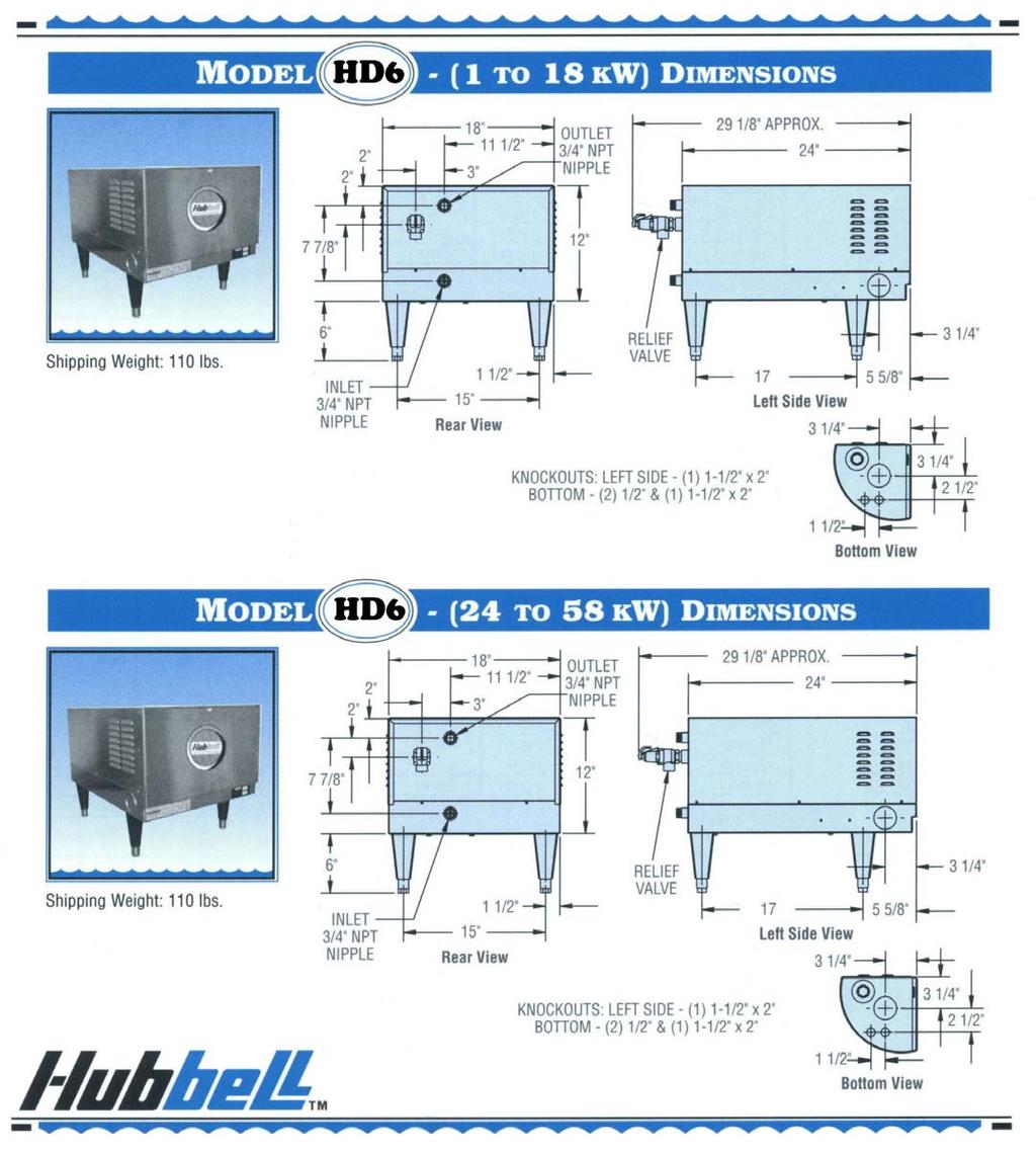
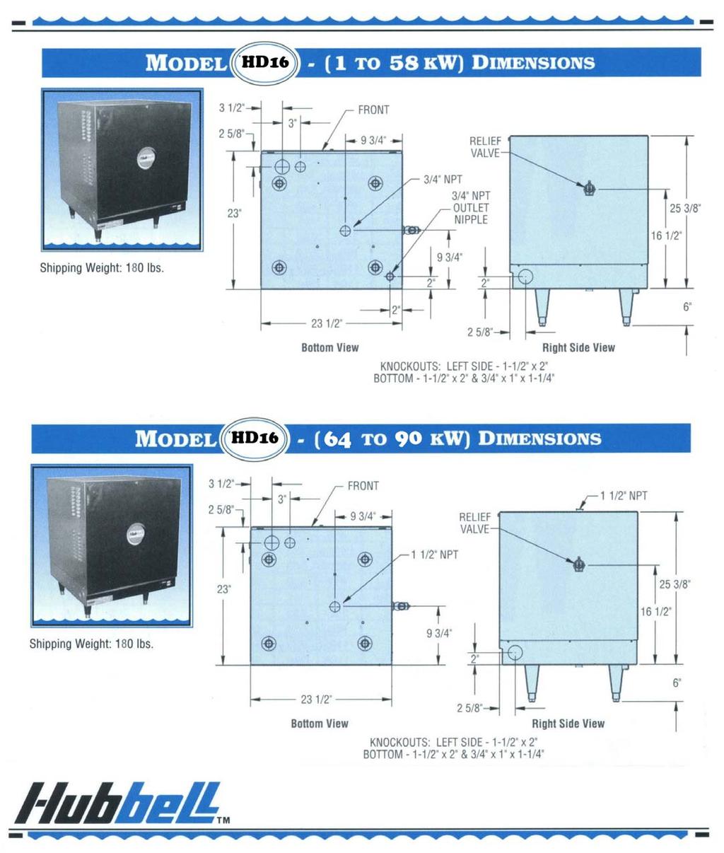
19 Typical HD6 Plumbing Connections (Rear View) Typical HD16 (1-58 kw) Plumbing Connections (Front View) 19
20 Typical HD16 (64-90 kw) Plumbing Connections (Front View) 20 SECTION III SCHEDULED MAINTENANCE AND OPERATION WARNING / CAUTION Before performing any maintenance procedure, make certain the power supply is turned OFF and cannot accidentally be turned on. MAINTENANCE AND OPERATION The water heater is automatic in its operation. It will maintain a full tank of water at the temperature setting of the controller. The water heater should not be turned on without first making sure that the tank is full of water and that all air has been released. FREEZING The tank should be fully drained in the event the electricity has been turned off and if there is danger of freezing. CONTROLLER OPERATION NOTE: All controller variables come preset from the factory to include a preset temperature of 185 F. 1. To turn unit on or off: a. Press the ON/OFF button on the display module. b. Note that the controller will resume its last mode of operation if power is disconnected. 2. To change setpoint temperature (the temperature is fully adjustable from 32 to 194 F (0-90 C): a. Press the UP and DOWN arrows simultaneously to enter setpoint change mode. b. Press the UP or DOWN button to change the setpoint temperature. c. Pressing and holding the UP or DOWN button will scroll through the setpoint temperature. d. To leave setpoint change mode
21 i. Wait 5 seconds without pushing any buttons or press the UP and DOWN buttons simultaneously. 3. To view the number of operational hours (the number of hours when a contactor is pulled in) and software version: a. Press the UP and DOWN arrows simultaneously to enter setpoint change mode. b. Press the ON/OFF button. c. Display will flash the software version (e.g. R14), HRS, followed by the hours in thousands of hours, followed by the hours. i. Example: r 14, H r S, l2 3, 4 5 6; indicates software version R1.4 and 123,456 hours. d. To leave operational hours mode i. Wait 5 seconds without pushing any buttons or press the UP and DOWN buttons simultaneously. 4. Configuration Menu. (NOTE: Configuration menu change should only be made by qualified personnel). a. To enter the configuration menu, press and hold the UP, DOWN, and ON/OFF buttons simultaneously for 5 seconds. b. To scroll through menu settings, press the ON/OFF button. c. To make a change to a menu setting use either the UP or DOWN arrow. d. Settings: i. Relays sets the number of magnetic contactors used in the heater. 1. r ##, where ## is the number of magnetic contactors (01 or 02). With XB1 installed ## can be 01 through 06. ii. Low water detection sets the low water detection on or off. 1. LOn, for low water on. 2. LOF, for low water off. (Factory Default) Note: The controller utilizes a conductivity type low water detection system. Due to the low conductivity of the DI/RO water, the conductivity sensor is turned off. A float type low water sensor is used in place of the conductivity sensor. iii. Low water reset sets the low water reset for either automatic or manual 1. LAU, for low water automatic reset. (Factory Default) 2. LAn, for low water manual reset. iv. Temperature units sets the temperature units to either degrees Fahrenheit or Celsius. 1. DEF, for degrees Fahrenheit. (Factory Default) 2. DEC, for degrees Celsius. v. Differential sets the number of degrees below setpoint that the heater will resume heating after it has achieved setpoint. 1. d ##, where ## is the differential in degrees (1 to 20). (Factory set at 02) vi. Display sets the display to either setpoint or actual temperature. 1. dss, for display setpoint temperature. (Factory Default) 2. dst, for display actual temperature. vii. Heater Interlock sets the heater interlock mode to on or off. (Only available with r23 or later software). 1. HoF, to disable the 24-volt interlock feature. (Factory Default) 2. Hon, to enable the 24-volt interlock feature. viii. XB1 Temperature Setpoint sets the setpoint for the operation of the XB1 relay operation. e. To leave the configuration menu, wait 5 seconds without pushing any buttons or press the UP and DOWN buttons simultaneously. 21
22 5. To reset any high-limit, no probe, or low water (when in manual reset mode) fault condition, press the RESET button. 6. Display a. By default the display will show the setpoint of the heater. b. The decimal points on the display, as shown below, indicate that the controller is calling for a contactor to pull in. ANNUAL INSPECTION 1. Monitor water temperature a. Let water heater completely heat to a designated temperature setting. b. After controller satisfies (that is, when the magnetic contactor actually clicks off), draw water from as close as possible heater outlet and measure the temperature. c. Compare the water temperature of outlet water to the temperature setting of the display when it satisfies. Normal variation between the two points is approximately + 5 F. d. If these two readings do not coincide within acceptable tolerances and verification has been made of the accuracy of the temperature-reading gauge, replace the control board and/or the sensor probe. 2. Lift test lever on relief valve and let water run through valve for a period of approximately 10 seconds. This will help flush away any sediment that might build up in water passageways. 3. Inspect element for leakage as follows: a. Shut off power supply. b. Remove front cover. c. Visually inspect around heating element for evidence of leaks. d. Rub around the heating element with a rag. Check for any evidence of moisture. If moisture is present or a water drip is observed, follow procedure outlined in Section V. CAUTION: The area around the heating element may be hot. 4. Scale and mineral build-up on heating elements is a normal condition. It is recommended that the heating element be removed for examination and if scaled, should be cleaned. In an area of known hard or poor water conditions, the elements may need to be checked more frequently. This will improve the efficiency of the heater and increase the element life. NOTE: Failure of the elements due to scale and mineral build-up is not covered under warranty. See warranty for complete details. a. Shut off power supply. b. Drain the tank. c. Remove front cover. d. Disconnect the element wiring. It is recommended that one element at a time is removed to simplify re-wiring. e. Unscrew element. f. Lime scale removal 22
23 i. Place limed ends of the heating element in a de-limer solution, designed for potable water applications, and allow lime to dissolve. Do not allow de-limer to contact heating element terminals. g. Other scale removal i. Silicates, sulfates, and aluminates must be removed by scraping or other mechanical means. De-limers will not dissolve these types of scale. h. Flush the cleaned ends of the elements with clean water. i. Re-install element with new o-ring. j. Re-attach element wires. k. Continue until all heating elements are cleaned. l. Fill the heater following the filling instructions provided in Section II and check around the elements for leaks. m. Re-apply power. 5. Check for loose electrical connections. Tighten as necessary. SECTION IV TROUBLESHOOTING ERROR MESSAGES 1. Err, No, Prb a. This message will flash when the controller does not detect that the probe is connected to the control board. To clear this error reinsert the probe connector and press RESET. 2. Err, too, hot, ### (where ### is the actual temperature of the water.) a. This message will display if the temperature of the water exceeds the high limit temperature setpoint. To clear this error, wait until the temperature is below the operating setpoint and press RESET. Note that the unit will not reset until the indicated temperature is below 195 F. If this message continually occurs, follow the troubleshooting flow chart for continuous over-temperature condition. 3. Err, No, H2O a. If this message is displayed, verify that the low water detection is turned off. 4. Err, H2O, LEA a. This message displays if the leak detection sensor determines there is water in the base of the heater shell. To clear this message, remove the water from the leak detection sensor. Check the unit and piping for leaks. 5. CC a. This message displays if the display cable is installed into the control board backwards. To clear this message, remove and correctly install the display cable a. This message indicates that the probe is likely out of calibration. To clear this message, it is recommended that the probe be removed and replaced. 7. HLd a. This message indicates that the 24-volt interlock feature is enabled, there is no 24-volt signal present, and the heater is in standby mode. If it is not the intention to operate the heater with the 24-volt interlock feature, this feature should be disabled as shown in the controller operation section. (Only available with r23 or later software). CONTACTOR CARE 1. A chattering or humming from the contactor is due to dust or debris on the contact points that prevents the contactor from making proper contact. The debris can be removed by utilizing a can of antistatic cleaning and dusting spray (pressurized air) and spraying through the side of the contactor to remove the debris. 23
24 LOW WATER CUT-OUT 1. Due to the low resistivity of DI/RO water, a 316L stainless steel float type low water cutout is supplied in lieu of a conductivity type. This device will help protect the elements from energizing when there is insufficient water in the tank. The float type low water cutout will disengage the control circuit during low/no water conditions and will auto-reset when the water reaches a safe level. The conductivity low water detection system incorporated in the T1000 digital controller should be disabled for DI/RO water applications. DISPLAY BUTTONS 1. If the display randomly changes or does not respond when the buttons are pressed, loosen the four (4) screws holding the display to the base, reseat the display in the center of the opening, and re-tighten the screws. MISCELLANEOUS 1. If the display flashes when the unit is first turned on or turned on after maintenance, check that the J5 terminal on the controller is engaging all four pins on the board. 2. Note that before replacing the control board, display, or probe, it is recommended that the power supply to the heater be turned off at the main circuit breaker disconnect to the heater to reset and clear the electronic controller. GENERAL TROUBLESHOOTING Symptom Probable Cause Corrective Action Low incoming water temperature. Water reaches setpoint temperature but does not last through the entire process cycle. Temperature and pressure relief valve seeps. Incoming water temperature is dropping. Heater may be undersized. Incorrect voltage. If two magnetic contactors are utilized, one is not energizing. One or more elements are not energizing. Anti-siphon valve or check valve installed in the cold water inlet line. Incoming water temperature must be adequate for the heater size. Increase the incoming water temperature. Primary water supply is not adequate to continually provide correct temperature in sufficient quantities. Increase the supply of primary cold water. The heater must be properly sized for the incoming water and rinse requirements of the process. If required, replace with a properly sized unit. Voltage available at the heater must be correct for unit. Verify voltage on all phases matches nameplate on the heater. Verify that both magnetic contactors are operating. If not, see the Magnetic Contactor Troubleshooting section. Verify that each element is drawing the correct amperage. Replace elements as required. Remove the anti-siphon valve or the check valve to allow for the expansion of the water or install a back pressure relief valve. 24
25 Symptom Probable Cause Corrective Action Unit is overheating due See the P65SS Probe Troubleshooting to improper P65SS section. probe calibration. Temperature and pressure relief valve opens and/or high limit temperature error occurs. Water at the outlet is not the proper temperature. Water heater does not heat at all. Unit is overheating due to the magnetic contactor staying in the closed position. Gauge(s) not reading correctly. Temperature setpoint too low. Water heater piping to point of use is not insulated. Bypass valve (if installed) is open or allowing water to pass when closed. Main supply circuit breaker tripped. Water heater circuit breaker tripped. Heater in high limit. Low water error. Magnetic contactor does not energize. No power to control board (T1000) or display (TD1000) not lit. Element Failure. No Water in Tank. Incorrect Configuration Settings See the Magnetic Contactor Troubleshooting section. Check the temperature of the water with a thermometer to verify the gauges are working properly. Replace gauges, if required. Adjust the temperature setpoint. If there is more than 5 linear feet of piping between the heater and the process, the piping should be wrapped in insulation or a recirculating system should be installed. Verify that the bypass valve between the hot and cold water lines is closed. If condition continues, replace the bypass valve. Check and/or reset the circuit breaker. If unit is supplied with a circuit breaker, check and/or reset the circuit breaker. If a high limit error occurs, allow water to cool and press the reset button. If error continues see symptom Temperature and pressure relief valve opens and/or high limit temperature error occurs. Verify that the low water setting is set to OFF in the configuration. If error is still present replace the P65SS probe and/or T1000 controller. See the Magnetic Contactor Troubleshooting section. Reseat the display (TD1000) ribbon cable in the control board (T1000) connector. If the display is still not lit, see the Control Board (T1000) / Display (TD1000) Troubleshooting section. Disconnect the wires from each element and verify that the resistance (ohms) value for each element is correct. Replace elements as required. With power off, check for continuity at the float type low water cut-off leads. If water is present and there is no continuity, replace the float type low water cut-off. Verify and correct configuration settings as required. 25
26 CONTROL BOARD (T1000) / DISPLAY (TD1000) TROUBLESHOOTING 1. Verify proper power supply voltage between each phase (L1 to L2, L2 to L3, and L1 to L3). The power supply voltage should match the voltage listed on the heater nameplate. If voltage is incorrect, check main supply wiring or replace unit with proper heater. 2. Check for 208/240VAC between pin 1 (white wire) and pin 2 (black wire) of the J5 connector on the T1000 control board. If no voltage is present, skip to step If 240VAC is present, check for 24VDC between D1 and ground. If 24VDC is present replace the display (TD1000). If 24VDC is not present replace the control board (T1000). Probe Ground (J7) Display Cable Expansion (J1) Leak Detection Wire (J2) Ground Wire (J8) (D1) Probe Cable (J3) Alarm Relay (J4) Power Wire (Common, White) Power Wire (Black) Connector (J5) Wire to #1 Contactor (yellow) Wire to #2 Contactor (red) 4. If a transformer is installed, verify proper power supply voltage to the primary side of the transformer and verify approximately 240VAC on the secondary side of the transformer. If voltage is present of the primary side but not on the secondary side, replace the transformer. 5. If circuit breakers are installed, verify that the circuit breaker is ON. Verify proper power supply voltage between each phase (L1 to L2, L2 to L3, and L1 to L3) to the line side of each circuit breaker and to the load side of each circuit breaker. If voltage is present of the line side but not on the load side, replace the circuit breaker. 6. Verify that the heater is wired according to the proper wiring schematic for the unit. Correct as required. If unit still does not operate, contact the factory. MAGNETIC CONTACTOR TROUBLESHOOTING 1. With the unit ON and calling for heat, check for lit decimal points on the display. If the unit has a single contactor, the first decimal to the right of the display should be lit. If two decimals are lit, verify that the configuration is set for one contactor. If the unit has two contactors, verify that two decimals are lit. If only one decimal is lit, verify that the configuration is set for two contactors. If no decimals are lit, continue to the P65SS Probe Troubleshooting section. 2. With the unit ON and calling for heat and one decimal lit, check for 240VAC between pin 1 (white wire) and pin 4 (yellow wire) of the J5 connector on the T1000 control board. If no voltage is present, replace the control board (T1000). If voltage is present, check for voltage across the contactor coil. If voltage is present at the contactor coil, replace the magnetic contactor. If no voltage is present, verify that the heater is wired according to the proper wiring schematic for the unit. 3. If the unit has two contactors, with the unit ON and calling for heat and two decimals lit, check for 240VAC between pin 1 (white wire) and pin 3 (red wire) of the J5 connector on the T1000 control board. If no voltage is present, replace the control board (T1000). If 26
27 voltage is present, check for voltage across the contactor coil. If voltage is present at the contactor coil, replace the magnetic contactor. If no voltage is present, verify that the heater is wired according to the proper wiring schematic for the unit. P65SS PROBE TROUBLESHOOTING 1. Unplug and reseat the P65SS probe wire in the jack on the T1000 control board. Note that the error message Err, No, Prb will be displayed and the reset button must be pressed to clear the message. 2. If problem persists, unplug the P65SS probe from the control board and plug into the RJ45 pigtail (not supplied). 3. If the problem is with temperature control or high limit: a. Change the configuration to dst to display the actual water temperature. b. Check the temperature of the water with a thermometer and compare that with the temperature on the display. If the two temperatures coincide, replace the T1000 control board. If the two temperatures do not coincide, continue to the next step. c. Unplug the P65SS probe from the control board and plug into the RJ45 pigtail (not supplied). Check the resistance value (ohms) between the blue wire of the pigtail (#1) and the red wire of the pigtail (#4). Compare the resistance value measure with the chart below at the measured temperature of the water. If the two values coincide, replace the T1000 control board. If the two values do not coincide, replace the P65SS sensor 4. If the problem is with low water: a. Verify that low water is set to OFF in the configuration menu. Thermistor Resistance vs. Temperature Water Temperature Resistance (±3%) 70 F 11883Ω 80 F 9299Ω 90 F 7334Ω 100 F 5828Ω 110 F 4664Ω 120 F 3758Ω 130 F 3048Ω 140 F 2488Ω 150 F 2043Ω 160 F 1687Ω 170 F 1400Ω 180 F 1169Ω 190 F 980Ω 27
28 SECTION V SERVICING AND REPLACEMENT OF PARTS WARNING / CAUTION Before servicing or replacing any part, make sure to turn the power supply to the unit OFF. HEATING ELEMENT 1. Disconnect power from unit. 2. Shut off incoming water supply. 3. Attach hose to drain connection. 4. Lift manual release lever on relief valve to let air into system or break union on outgoing water line. 5. Drain water from tank. 6. Disconnect the wires from the heating element terminals. 7. Unscrew element with a 1-7/8 6-point socket with no bevel. O-Ring Groove O-Ring Terminal Connections #220 Viton O-Ring 8. Install new #220 Viton o-ring gasket and install new heating element. NOTE: Hubbell recommends lubricating the o-ring with Parker O-Lube prior to installation. 9. Rewire element according to the wiring diagram as shown in the Section II. 10. Fill tank and check around element for any leaks. MAGNETIC CONTACTOR 1. Disconnect power from unit. 2. Disconnect line and load wires to contactor. 3. Disconnect the control circuit wires. Control Wires Line Wires Load Wires Mounting Screws 4. Loosen holding screws and remove contactor. 5. Replace with new contactor using reverse procedure. CONTROL BOARD 1. Disconnect power from unit. 2. Disconnect display cable, probe cable (J3) and probe ground (J7), leak detection wire (J2), ground wire (J8), and terminal block (J5) from the control board. NOTE: The terminal block (J5) is removable from the control board. Grasp the terminal block on the ends and pull straight away from the board. 28
 Wire to #2 Contactor (red) Note: Probe connector J3 comes filled with a dielectric gel that should remain in the connector. 3.")
29 Probe Ground (J7) Display Cable Expansion (J1) Leak Detection Wire (J2) Ground Wire (J8) (D1) Probe Cable (J3) Alarm Relay (J4) Power Wire (Common, White) Power Wire (Black) Connector (J5) Wire to #1 Contactor (yellow) Wire to #2 Contactor (red) Note: Probe connector J3 comes filled with a dielectric gel that should remain in the connector. 3. Remove four (4) screws securing control board to panel. 4. Remove and replace control board. 5. Reconnect wires disconnected in step 2. NOTE: When reconnecting the ribbon cable, be sure to have the key on the cable align with the slot in the connector. 6. Connect power to unit. RELIEF VALVE 1. Disconnect power from unit. 2. Shut off incoming water supply. 3. Attach hose to drain connection. 4. Lift manual release lever on relief valve to let air into system or break union on outgoing water line. 5. Drain water from tank. 6. Disconnect overflow piping. 7. Unscrew relief valve, remove assembly and replace with new one. 8. Connect overflow piping. 9. Turn on incoming water supply and check for leaks. 10. Connect power to unit. P65SS SENSOR PROBE 1. Disconnect power from the unit. 2. Unplug the P65SS probe connector from J3 and the probe ground from J7 on the T1000 control board. Probe Connection (J3) 29


30 3. Twist the cord and shrink-wrap end of the P65SS probe (or cut the shrink-wrap with a sharp knife) to loosen the P65SS sensor assembly from the P65SS thermowell. 4. Remove the old P65SS sensor assembly by pulling on the cord coming out of the P65SS thermowell. Note: It is unnecessary to unscrew the thermowell from the vessel to replace the P65SS sensor. Cord P65 Sensor Shrink-Wrap Cap 5. Insert the new P65SS sensor assembly into the P65SS thermowell. Be sure to insert the sensor until the shrink-wrap cap engages the threads on the end of the thermowell. Note: The new sensor and cord assembly is push-fit onto the end of the thermowell threads. Do not twist the new sensor and cord assembly into the thermowell. The thermal conductive heat transfer paste inside the thermowell is sufficient for replacement sensors. Adding additional paste is not required. 6. Plug P65SS probe connector into the T1000 control board. 7. Turn on power to the unit. If display shows Err, No, Prb, press the reset button. P65SS THERMOWELL 1. Follow steps 1-4 for removing the P65SS Sensor Probe above. 2. Shut off incoming water supply. 3. Attach hose to drain connection. 4. Lift manual release lever on relief valve to let air into system or break union on outgoing water line. 5. Drain water from tank. 6. Remove the thermowell from tank using a 13/16 socket. 7. Install new #115 Viton o-ring gasket and install new thermowell. NOTE: Hubbell recommends lubricating the o-ring with Parker O-Lube prior to installation. WARNING: Do not remove the jam nut. Thermowell 8. Reinstall or install a replacement P65 sensor probe in accordance with steps 5 and 6 above. 9. Refill tank. 10. Check for leaks. Retighten as required. 11. Turn on power to the unit. 12. Note that to resume operation the controller will need to be reset by pressing the RESET button on the display. CAUTION: Do not use plumber s tape/teflon tape/pipe dope when installing the P65SS Thermowell. Lubricate O-ring prior to installation. Tighten probe at the brass hex flats only. 30

31 LOW WATER SWITCH 1. Disconnect power from unit. 2. Shut off incoming water supply. 3. Attach hose to drain connection. 4. Lift manual release lever on relief valve to let air into system or break union on outgoing water line. 5. Drain water from tank. 6. Disconnect the two wires of the low water switch. 7. Unscrew and remove the low water switch from vessel. 8. Thread new low water switch into vessel. NOTE: This is an NPT thread and will require Teflon plumbing tape or thread sealant. NOTE: Etched into the hex of the low water switch is NO and NC and/or arrows. NO must be facing upward (and/or the arrows must point upward). 9. Connect two wires from low water switch as indicated in the appropriate wiring diagram. 10. Turn on incoming water supply and check for leaks. 11. Turn on power to the unit. NOTE: NO must face toward the top. 31
OPERATING AND MAINTENANCE MANUAL FOR ELECTRIC BOOSTER HEATER
 OPERATING AND MAINTENANCE MANUAL FOR ELECTRIC BOOSTER HEATER ELECTRIC HEATER COMPANY BASE MODEL J 2010 Edition ASME ANSI/NSF5 HUBBELL ELECTRIC HEATER COMPANY 45 SEYMOUR STREET P.O. BOX 288 STRATFORD, CT
OPERATING AND MAINTENANCE MANUAL FOR ELECTRIC STAINLESS STEEL HEATER FOR DEIONIZED (DI) WATER ELECTRIC HEATER COMPANY BASE MODEL D
 WATER ELECTRIC HEATER COMPANY BASE MODEL D") OPERATING AND MAINTENANCE MANUAL FOR ELECTRIC STAINLESS STEEL HEATER FOR DEIONIZED (DI) WATER ELECTRIC HEATER COMPANY BASE MODEL D HUBBELL ELECTRIC HEATER COMPANY P.O. BOX 288 STRATFORD, CT 06615 PHONE:
OPERATING AND MAINTENANCE MANUAL FOR ELECTRIC STAINLESS STEEL HEATER FOR DEIONIZED (DI) WATER ELECTRIC HEATER COMPANY BASE MODEL D HUBBELL ELECTRIC HEATER COMPANY P.O. BOX 288 STRATFORD, CT 06615 PHONE:
INSTALLATION, OPERATION AND MAINTENANCE MANUAL FOR COMMERCIAL INDIRECT POWERED WATER HEATER
 INSTALLATION, OPERATION AND MAINTENANCE MANUAL FOR COMMERCIAL INDIRECT POWERED WATER HEATER ELECTRIC HEATER COMPANY BASE MODEL T Edition 0 HUBBELL ELECTRIC HEATER COMPANY P.O. BOX 88 STRATFORD, CT 0665
American Dish Service
 American Dish Service INSTALLATION INSTRUCTIONS Model JDS12 (T) or (R) Muffler Booster (T) 12kW, 240v, 3-ph, (R) 12kW, 208v, 3-ph Manufactured by Hubbell Electric Heater Company for use on American Dish
OPERATING AND MAINTENANCE MANUAL FOR COMMERCIAL ELECTRIC WATER HEATER. ELECTRIC HEATER COMPANY BASE MODEL SH and H
 OPERATING AND MAINTENANCE MANUAL FOR COMMERCIAL ELECTRIC WATER HEATER ELECTRIC HEATER COMPANY BASE MODEL SH and H HUBBELL ELECTRIC HEATER COMPANY P.O. BOX 288 STRATFORD, CT 06615 PHONE: (203) 378-2659
OPERATING AND MAINTENANCE MANUAL FOR PACKAGED ELECTRIC TEPID WATER HEATING SYSTEMS BASE MODEL ESS
 OPERATING AND MAINTENANCE MANUAL FOR PACKAGED ELECTRIC TEPID WATER HEATING SYSTEMS BASE MODEL ESS THERM-OMEGA-TECH, INC. 353 IVYLAND RD, WARMINSTER, PA 18974 PHONE: (877) 379-8258 INTERNET: http://www.thermomegatech.com
OPERATING AND MAINTENANCE MANUAL FOR PLATE HEAT EXCHANGER INDIRECT FIRED WATER HEATER. Electric Heater Company Base Model "BWXP"
 OPERATING AND MAINTENANCE MANUAL FOR PLATE HEAT EXCHANGER INDIRECT FIRED WATER HEATER Electric Heater Company Base Model "BWXP" HUBBELL ELECTRIC HEATER COMPANY P.O. BOX 288 STRATFORD, CT 06615 PHONE: (203)
Process Water Heater For Industrial Applications All Voltages, Single or Three Phase Up To 88 KW
 MODEL V Process Water Heater For Industrial Applications All Voltages, Single or Three Phase Up To 88 KW Features Industrial Grade Construction Stainless steel pressure vessel provides maximum service
INSTALLATION, OPERATION AND MAINTENANCE MANUAL FOR COMPACT POINT-OF-USE ELECTRIC WATER HEATER
 INSTALLATION, OPERATION AND MAINTENANCE MANUAL FOR COMPACT POINT-OF-USE ELECTRIC WATER HEATER BASE MODEL CE110 2015 Edition HUBBELL ELECTRIC HEATER COMPANY P.O.BOX 288 STRATFORD, CT 06615 PHONE: (203)
INSTALLATION, OPERATION, AND MAINTENANCE MANUAL FOR THE HUBBELL MODEL TX / HX TANKLESS WATER HEATER
 INSTALLATION, OPERATION, AND MAINTENANCE MANUAL FOR THE HUBBELL MODEL TX / HX TANKLESS WATER HEATER ELECTRIC HEATER COMPANY Edition 2012A HUBBELL ELECTRIC HEATER COMPANY P.O. BOX 288 STRATFORD, CT 06615-0288
INSTALLATION, OPERATION, AND MAINTENANCE MANUAL FOR THE HUBBELL MODEL JTX TANKLESS BOOSTER HEATER ELECTRIC HEATER COMPANY
 INSTALLATION, OPERATION, AND MAINTENANCE MANUAL FOR THE HUBBELL MODEL JTX TANKLESS BOOSTER HEATER ELECTRIC HEATER COMPANY Edition 2011 HUBBELL ELECTRIC HEATER COMPANY P.O. BOX 288 STRATFORD, CT 06615-0288
SERVICE MANUAL. Bradford White ElectriFLEX HD (Heavy Duty) Commercial Electric Water Heater CEHD SERIES Immersion Thermostat Models
 Commercial Electric Water Heater CEHD SERIES Immersion Thermostat Models") Bradford White ElectriFLEX HD (Heavy Duty) Commercial Electric Water Heater CEHD SERIES Immersion Thermostat Models SERVICE MANUAL Troubleshooting Guide and Instructions for Service (To be performed ONLY
Bradford White ElectriFLEX HD (Heavy Duty) Commercial Electric Water Heater CEHD SERIES Immersion Thermostat Models SERVICE MANUAL Troubleshooting Guide and Instructions for Service (To be performed ONLY
INSTALLATION, OPERATION, AND MAINTENANCE MANUAL FOR THE HUBBELL MODEL JTX / JHX TANKLESS BOOSTER HEATER
 INSTALLATION, OPERATION, AND MAINTENANCE MANUAL FOR THE HUBBELL MODEL JTX / JHX TANKLESS BOOSTER HEATER ELECTRIC HEATER COMPANY * The Hubbell Model JTX is designed for use with conveyor and flight type
INSTALLATION, OPERATION AND MAINTENANCE MANUAL FOR POINT OF USE STEAM FIRED WATER HEATER ELECTRIC HEATER COMPANY BASE MODEL PS
 INSTALLATION, OPERATION AND MAINTENANCE MANUAL FOR POINT OF USE STEAM FIRED WATER HEATER ELECTRIC HEATER COMPANY BASE MODEL PS Edition 2011 HUBBELL ELECTRIC HEATER COMPANY P.O. BOX 288 STRATFORD, CT 06615
INSTALLATION, OPERATING & MAINTENANCE INSTRUCTIONS FOR 350 SERIES CIRCULATION HEATERS
 INDEECO Circulation Heaters are designed to provide years of trouble free operation if properly installed and maintained. Please read and follow these instructions for installing and maintaining the heater.
INSTALLATION, OPERATION, AND MAINTENANCE MANUAL FOR THE HUBBELL TANKLESS WATER HEATER
 INSTALLATION, OPERATION, AND MAINTENANCE MANUAL FOR THE HUBBELL TANKLESS WATER HEATER ELECTRIC HEATER COMPANY Edition 2016A HUBBELL ELECTRIC HEATER COMPANY P.O. BOX 288 STRATFORD, CT 06615-0288 PHONE:
Commercial Electric Energy Saver Water Heater IMMERSION AND SURFACE MOUNTED THERMOSTAT MODELS
 Energy Saver Commercial Electric Energy Saver Water Heater IMMERSION AND SURFACE MOUNTED THERMOSTAT MODELS SERVICE MANUAL Troubleshooting Guide and Instructions for Service (To be performed ONLY by qualified
INSTALLATION AND SERVICE MANUAL
 INSTALLATION AND SERVICE MANUAL Electric Power Water Heater 12kW 162kW NOTE: retain this manual for future reference Installation and service must be performed by Qualified Service Personnel Only. WARRANTY:
OPERATING AND MAINTENANCE MANUAL FOR BOILER WATER OR HIGH TEMPERATURE HOT WATER (HTHW) POWERED WATER HEATER
 POWERED WATER HEATER") OPERATING AND MAINTENANCE MANUAL FOR BOILER WATER OR HIGH TEMPERATURE HOT WATER (HTHW) POWERED WATER HEATER ELECTRIC HEATER COMPANY BASE MODEL BW and BWH HUBBELL ELECTRIC HEATER COMPANY P.O. BOX 288 STRATFORD,
OPERATING AND MAINTENANCE MANUAL FOR BOILER WATER OR HIGH TEMPERATURE HOT WATER (HTHW) POWERED WATER HEATER ELECTRIC HEATER COMPANY BASE MODEL BW and BWH HUBBELL ELECTRIC HEATER COMPANY P.O. BOX 288 STRATFORD,
Packaged Instantaneous Circulation Heater Full KW Selection In All Voltages, Single or Three Phase
 Features Heavy Duty Construction Constructed with high grade materials to ensure long operating life Turn-Key package is simple to specify and operate Factory wired electrical controls provide trouble-free
OPERATING AND MAINTENANCE MANUAL FOR VERTICAL IMMERSION HEATED STEAM BOILERS. Technical Control Systems Limited MODELS "VIHS"
 OPERATING AND MAINTENANCE MANUAL FOR VERTICAL IMMERSION HEATED STEAM BOILERS Technical Control Systems Limited MODELS "VIHS" Technical Control Systems Ltd Treefield Industrial Estate Gildersome, Leeds
Indirect Fired Water Heater
 Indirect Fired Water Heater 35-119 Gallon Capacities Features Heavy Duty Construction Hydrastone cement lining provides long tank life Copper-silicon tappings cannot rust or corrode High impact composite
SECTION DOMESTIC WATER HEATERS
 SECTION 223500 PART 1 - GENERAL 1.1 RELATED DOCUMENTS A. Drawings and general provisions of the Contract, including General and Supplementary Conditions and Division 01 Specification Sections, apply to
MASTER JOCKEY PUMP CONTROLLER. Model JPCE INSTRUCTION MANUAL. C 2018 Master Control Systems, Inc
 MASTER JOCKEY PUMP CONTROLLER Model JPCE INSTRUCTION MANUAL C 2018 Master Control Systems, Inc TABLE OF CONTENTS Important Safety Information. Page 3 General Description and Installation.. Page 4 Model
WATLOW IND. WATROD Modular Duct Heater Installation & Maintenance Manual I&M NUMBER: Page: 1 Date:6/11/2008 Rev: 2
 I&M NUMBER: 316-42-15-1 Page: 1 _ Pre Installation Check to make sure that heater received is the same as that ordered. Elements may come in contact with each other during shipment. Minor adjustments to
ASME Packaged Electric Water Heater
 MODEL SH & H ASME Packaged Electric Water Heater 15-1600 KW - All Voltages & Phases, 80-5000 Gallon Capacity Features Reliable Packaged System Only high grade materials used in construction to ensure long
STEAMPRO. Steam Generator Troubleshooting and Service Guide
 STEAMPRO Steam Generator Troubleshooting and Service Guide TABLE OF CONTENTS Page PREFACE... 1 I. STEAMPRO STEAM GENERATOR SYSTEM...2 II. PLUMBING AND ELECTRICAL...3-4 III. SYSTEM OVERVIEW... 5-10 IV.
OPERATING AND MAINTENANCE MANUAL FOR STEAM FIRED WATER HEATER. ELECTRIC HEATER COMPANY BASE MODEL ST and STH
 OPERATING AND MAINTENANCE MANUAL FOR STEAM FIRED WATER HEATER ELECTRIC HEATER COMPANY BASE MODEL ST and STH HUBBELL ELECTRIC HEATER COMPANY P.O. BOX 288 STRATFORD, CT 06615 PHONE: (203) 378-2659 FAX: (203)
Installation and Operating Instructions ISH ELECTRIC STEAM SUPERHEATER
 Installation and Operating Instructions ISH ELECTRIC STEAM SUPERHEATER 1 Installation and Operating Instructions ISH ELECTRIC STEAM SUPERHEATER FOR YOUR SAFETY This manual supplies information on the application,
INSTALLATION, OPERATING & MAINTENANCE INSTRUCTIONS FOR 870 SERIES INDUSTRIAL CONTROL PANELS
 INSTALLATION, OPERATING & MAINTENANCE INSTRUCTIONS FOR 870 SERIES INDUSTRIAL CONTROL PANELS GENERAL INDEECO Industrial Control Panels are designed to provide years of trouble free operation if properly
ITC 2000 HEATING CONTROL CABINET. Installation & Operation Manual
 ITC 2000 HEATING CONTROL CABINET Installation & Operation Manual VTI, Incorporated 24 McMillan Way Newark, DE 19713 Phone (302) 738 0500 FAX (302) 738 6594 Revision Level 0.03 Manual No. 90003314 June,
OPERATING AND MAINTENANCE MANUAL FOR INSTANTANEOUS STEAM FIRED WATER HEATER ELECTRIC HEATER COMPANY BASE MODEL F
 OPERATING AND MAINTENANCE MANUAL FOR INSTANTANEOUS STEAM FIRED WATER HEATER ELECTRIC HEATER COMPANY BASE MODEL F Edition 2013 HUBBELL ELECTRIC HEATER COMPANY P.O. BOX 288 STRATFORD, CT 06615 PHONE: (203)
Tankless On Demand Electric Water Heater
 ECO FRIENDLY 98% EFFICIENT ENERGY & WATER SAVING Model MTX Tankless On Demand Electric Water Heater Available Up To 54 KW in Single or Three Phase Voltages Marine Approvals American Bureau of Shipping
INSTALLATION INSTRUCTIONS AND OWNER S MANUAL FOR
 INSTALLATION INSTRUCTIONS AND OWNER S MANUAL FOR ELECTRIC ON-DEMAND TANKLESS WATER HEATERS: SpecAdvantage with PhD Technology SafeAdvantage with PhD Technology 208 and 480 VAC three phase 32 144 kw 600
Tankless Electric Water Heater Available up to 54 KW in Single or Three Phase Voltages
 Model HX/TX Tankless Tankless Electric Water Heater Available up to 54 KW in Single or Three Phase Voltages Features Heavy Duty Construction Constructed with high grade materials to ensure long operating
HOMEADVANTAGE II IMPORTANT SAFETY INFORMATION
 INSTALLATION INSTRUCTIONS & HOME OWNERS MANUAL HOMEADVANTAGE II HA008240 HA011240 HA013240 HA018240 HA024240 HA027240 HA036240 IMPORTANT SAFETY INFORMATION When installing or using any high voltage electrical
ELECTRIC SPA-PAK HEATER INSTALLATION & OPERATING INSTRUCTIONS
 ELECTRIC SPA-PAK HEATER INSTALLATION & OPERATING INSTRUCTIONS CATALOG NO.: 6100.53O Effective: 03-15-05 Replaces: 02-01-05 INTRODUCTION The SPA-PAK Spa Heaters have been designed to provide efficient,
INSTALLATION INSTRUCTIONS AND OWNER S MANUAL
 INSTALLATION INSTRUCTIONS AND OWNER S MANUAL ELECTRIC INSTANTANEOUS WATER HEATERS WITH PhD 208 and 480 VAC three phase 32 144 kw 600 VAC three phase 130 / 150 kw BEFORE ATTEMPTING ANY INSTALLATION OR SERVICE
INSTALLATION AND SERVICE MANUAL
 INSTALLATION AND SERVICE MANUAL SPACESAVER ELECTRIC BOOSTER HOT WATER HEATERS 4 kw to 54 kw, 208 Vac to 600 Vac, Single or Three Phase 180ºF instantaneous hot water for commercial dishwashers Suitable
J120 STEAM BOOSTER INSTALLATION, OPERATION, AND SERVICE MANUAL J120 STEAM BOOSTER. J120 Steam Booster Manual D
 INSTALLATION, OPERATION, AND SERVICE MANUAL J120 STEAM BOOSTER J120 STEAM BOOSTER J120 Steam Booster Manual REVISION HISTORY Revision Letter Revision Date Made by Applicable ECNs Details A 10-27-04 CBW
EcoSmart Troubleshooting Guide
 EcoSmart Troubleshooting Guide Models POU 3.5 & 6 kw This guide is designed for installers or homeowners to help troubleshoot any issues experienced during the lifetime of the tankless water heater. For
MASTER PRESSRE MAINTANENCE CONTROLLER. Models PMCE INSTRUCTION MANUAL. C 2018 Master Control Systems, Inc
 MASTER PRESSRE MAINTANENCE CONTROLLER Models PMCE INSTRUCTION MANUAL C 2018 Master Control Systems, Inc TABLE OF CONTENTS Important Safety Information. Page 3 General Description and Installation.. Page
Electric Mini Tank Water Heaters ME10 ME25 ME40 ME60
 Electric Mini Tank Water Heaters ME10 ME25 ME40 ME60 Installation and Operating Instruction Manual V01.2018 Table of Contents Important Safety Instructions 3 General Information 3/6 Technical Data 4-5
EEMAX SERIES-TWO WATER HEATERS
 EEMAX SERIES-TWO WATER HEATERS ELECTRIC INSTANTANEOUS WATER HEATER INSTALLATION GUIDE AND OWNERS MANUAL MODELS COVERED:- EX190 TC, T2-240/208 V EX144 TC, T2-240/208 V EX1608 TC, T2 208V EX160 TC, T2-277
Chromalox. Installation, Operation. Screw Plug Heating Solution Control Panel Assembly for Screw Plug Heaters RENEWAL PARTS IDENTIFICATION
 Chromalox Installation, Operation and RENEWAL PARTS IDENTIFICATION DIVISION SALES REFERENCE DATE 4 (Supersedes PG422-) DECEMBER, 2000 SECTION RAD PE440 6-058074-002 Screw Plug Heating Solution Control
PRO SERIES IMPORTANT SAFETY INFORMATION
 INSTALLATION INSTRUCTIONS & HOME OWNERS MANUAL PRO SERIES IMPORTANT SAFETY INFORMATION When installing or using any high voltage electrical appliance, basic safety precautions should always be followed.
Packaged Semi-Instantaneous Steam Fired Water Heater
 MODEL STX Packaged Semi-Instantaneous Steam Fired Water Heater Shell and Tube Style Heater Features Reliable Only high grade materials used in construction to ensure long operating life Heat exchange pressure
Commercial Electric Water Heater Gallon Capacity, up to 58 KW in all Three Phase Voltages, Over 6 KW in all Single Phase Voltages
 MODEL SE Commercial Electric Water Heater 6-119 Gallon Capacity, up to 58 KW in all Three Phase Voltages, Over 6 KW in all Single Phase Voltages Features Heavy Duty Construction High Efficiency Polyurethane
INSTALLATION INSTRUCTIONS FOR 8330*5511 MOUNTING KIT
 RV Products Division INSTALLATION INSTRUCTIONS FOR 8330*5511 MOUNTING KIT 8330-752 CONTROL BOX KIT (12 VDC COOL ONLY) 9330A755 CONTROL BOX KIT (12 VDC HEAT/COOL) 8530-750 CONTROL BOX KIT (24 VAC COOL ONLY)
CONTENTS Warranty Start-Up Procedure Installation Requirements Maintenance Trouble Shooting Electrical Service Components and Controls
 Warranty..........................1 Safety Warnings................1 Checking the Equipment..........1 Codes........................4 Installation Requirements Location......................4 Drain Pan
rev3 INSTALLATION & OPERATION MANUAL OIL CIRCULATING HEATING SYSTEM MODEL OSM
 216279-000 rev3 INSTALLATION & OPERATION MANUAL OIL CIRCULATING HEATING SYSTEM MODEL OSM IDENTIFYING YOUR SYSTEM IOM216279-000 The HOTSTART heating system is designed to heat fluids for use in marine
Installation Instructions Wall Ovens
 Installation Instructions Wall Ovens TESTED IN ACCORDANCE WITH THE LATEST EDITION OF UL858 STANDARD FOR HOUSEHOLD ELECTRIC COOKING APPLIANCES. IMPORTANT 1. Before beginning installation, please thoroughly
Portable CNA-Series - Large Industrial Heaters Tankless Water Heating Solutions
 Portable CNA-Series - Large Industrial Heaters Heavy duty industrial cart options simplify moving heater to various locations 36-72 kw (122,800-245,600 BTUs) Certified Lead-Free Design New & Improved Pressure
WATLOW ELECTRIC MFG CO. WATROD Duct Heater (module only) I& M Manual I&M NUMBER: Page: 1 Date: 11/25/2013 Rev: 4.00
 I& M Manual I&M NUMBER: Page: 1 Date: 11/25/2013 Rev: 4.00") I&M NUMBER: 316-42-16-1 Page: 1 Pre Installation Check to make sure that heater received is the same as that ordered. Elements may come in contact with each other during shipment. Minor adjustments to
I&M NUMBER: 316-42-16-1 Page: 1 Pre Installation Check to make sure that heater received is the same as that ordered. Elements may come in contact with each other during shipment. Minor adjustments to
High Capacity Instantaneous Steam Fired Water Heater
 MODEL F High Capacity Instantaneous Steam Fired Water Heater Features Compact High Capacity Design Packaged System Water heater is factory assembled on an all welded steel mounting frame to save time and
UNDERCOUNTER LABORATORY REFRIGERATORS and FREEZERS Installation, Operation and Maintenance Instructions
 UNDERCOUNTER LABORATORY REFRIGERATORS and FREEZERS Installation, Operation and Maintenance Instructions INSPECTION When the equipment is received, all items should be carefully checked against the bill
SNA-SKID Series - Preassembled Safety Shower Heater Skid Tankless Water Heating Solutions
 Pre-assembled skid system Back-to-Back heater models, SNA & SNAR High Flow Demand Safety Shower Applications 216-288 kw (737,000-983,000 BTUs) Temperature overshoot purge system NEMA 4 enclosure standard
INSTALLATION INSTRUCTIONS & HOME OWNERS MANUAL ECO 18 ECO 24 ECO 27 IMPORTANT SAFETY INFORMATION
 INSTALLATION INSTRUCTIONS & HOME OWNERS MANUAL ECO 18 ECO 24 ECO 27 IMPORTANT SAFETY INFORMATION As when installing or using any high voltage electrical appliance, basic safety precautions should always
Sun Bandit Hybrid Water Heater Installation and Operation Solar Hybrid Energy Systems Patent(s) Pending
 Pending") Solar Hybrid Energy Systems Patent(s) Pending Sun Bandit Hybrid Water Heater Installation and Operation Solar Hybrid Energy Systems Patent(s) Pending Instruction Manual Solar Hybrid Energy Systems Patent(s)
Solar Hybrid Energy Systems Patent(s) Pending Sun Bandit Hybrid Water Heater Installation and Operation Solar Hybrid Energy Systems Patent(s) Pending Instruction Manual Solar Hybrid Energy Systems Patent(s)
EEMAX ProAdvantage Series 1
 EEMAX ProAdvantage Series 1 ELECTRIC INSTANTANEOUS WATER HEATER INSTALLATION GUIDE AND OWNER S MANUAL MODELS COVERED: PA004120T 1Φ 120V PA008208T 1Φ 208V PA005240T 1Φ 240V PA007240T 1Φ 240V PA010240T 1Φ
Service Handbook. Servicing should only be performed by a Qualified Service Agent.
 Service Handbook COMMERCIAL ELECTRIC WATER HEATERS Technical Support and Parts: 800-456-9805 www.americanwaterheater.com MODELS STCE3-52/80/119 & ITCE3-52/80/119 INSTALLATION CONSIDERATIONS - PRE SERVICE
INSTALLATION INSTRUCTIONS FOR 7330C740 FLUSH MOUNT CEILING ASSEMBLY
 INSTALLATION INSTRUCTIONS FOR 7330C740 FLUSH MOUNT CEILING ASSEMBLY TABLE OF CONTENTS Warnings...3 Package Contents...3 General Information...3 Supply Ducting And Registers...3 Routing 115 VAC Wiring...5
Discontinued. SN Series - Safety Shower Heaters Tankless Water Heating Solutions. Standard Equipment. Construction. Code Compliance and Certifications
 36-144 kw (122,800-491,300 BTUs) Temperature overshoot purge system Certified Lead-Free Design NEMA 4 enclosure standard ASME and NB Certified options available Pressure Drop Advantage Dual Flow Activation
Duct and Rough Service Carbon Monoxide Sensor
 Product Identification and Overview Duct and Rough Service Carbon Monoxide Sensor BAPI s Carbon Monoxide Sensor offers enhanced electrochemical sensing with outstanding accuracy at low concentrations.
Keltech SNA-Series - Safety Shower Heaters Tankless Water Heating Solutions
 36-144 kw (122,800-491,300 BTUs) Temperature overshoot purge system Certified Lead-Free Design NEMA 4 enclosure standard ASME and NB Certified options available New & Improved Pressure Drop Advantage Dual
Water Boilers ME10EN, ME15EN. Table of Contents
 Water Boilers ME10EN, ME15EN Operator Manual Model ME15EN Model ME10EN Safety Information...2 Rough-In Drawing...3 Installation...4 Priming...5 Cleaning...5 Table of Contents Adjustments...6 Maintenance...7
PROVIDES TEPID WATER FOR EMERGENCY SHOWER
 PROVIDES TEPID WATER FOR EMERGENCY SHOWER Model EMV FEATURES Heavy Duty Construction Hydrastone cement lining provides tank longevity Copper-silicon alloy tappings cannot rust or corrode High impact composite
L A signature series TA T N E RE O, A L L A T S IN
 signature series COMMERCIAL STEAM GENERATORS INSTALLATION, OPERATION AND MAINTENANCE MANUAL INSTALLATION MANUAL COMMERCIAL STEAM GENERATOR SIGNATURE SERIES (SS) INTRODUCTION Steam Sauna manufactures steam
Installation, Operation, and Maintenance Manual RTE14S & RTE14S-2. For the Taco Bell "Rethermalizer" Model Numbers
 Installation, Operation, and Maintenance Manual For the Taco Bell "Rethermalizer" Model Numbers RTE14S & RTE14S-2 NOTICES There are three different types of notices that you should be familiar with, a
INSTALLATION INSTRUCTIONS
 INSTALLATION INSTRUCTIONS FCP2400D FCP3000D FCP3600D FCP4200D FCP4800D FCP6000D FCP2400C FCX2400C FCP3000C FCP3600C FCX3600C FCP4200C FCP4800C FCX4800C FCP6000C FCX6000C Require AMF001NHA Accessory No
Semi-Instantaneous Indirect Fired Water Heater
 MODEL BWX Semi-Instantaneous Indirect Fired Water Heater Use Boiler Water Or HTHW To Heat Domestic Water Features Reliable Only high grade materials used in construction to ensure long operating life Hydrastone
INSTALLATION INSTRUCTIONS FOR MOUNTING KIT
 RV Products Division INSTALLATION INSTRUCTIONS FOR 8330-5501 MOUNTING KIT 8330-752 CONTROL BOX KIT (12 VDC COOL ONLY) 9330B755 CONTROL BOX KIT (12 VDC HEAT/COOL) 8530-750 CONTROL BOX KIT (24 VAC COOL ONLY)
CNA-Series - Large Industrial Heaters Tankless Water Heating Solutions
 36-144 kw (122,800-491,300 BTUs) Certified Lead-Free Design New & Improved Pressure Drop Advantage Variable Temp Heat Exchanger NEMA 4 enclosure standard Independent Safeties ETL and cetl certified to
WAIWELA SERIES-TWO WATER HEATERS
 WAIWELA SERIES-TWO WATER HEATERS ELECTRIC INSTANTANEOUS WATER HEATER INSTALLATION GUIDE AND OWNERS MANUAL MODELS COVERED WET-12 T, TC, T2-240/208 V SPECIAL, V READ THE GENERAL SAFETY SECTION BEGINNING
Series 47 and 247 Mechanical Water Feeders. Series 47-2 and Combination Mechanical Water Feeder/Low Water Cut-Off ! WARNING
 Series 47 and 247 Mechanical Water Feeders McDonnell & Miller Installation & Maintenance Instructions MM-316(C) Series 47-2 and 247-2 Combination Mechanical Water Feeder/Low Water Cut-Off Series 47 Water
! WARNING. McDonnell & Miller Installation & Maintenance Instructions MM-315(C)
") Models 51, 51-S and 53 Boiler Water Feeders Models 51-2, 51-S-2 and 53-2 Feeder Cut-Off Combinations McDonnell & Miller Installation & Maintenance Instructions MM-315(C) OPERATION Maximum Water Supply
Models 51, 51-S and 53 Boiler Water Feeders Models 51-2, 51-S-2 and 53-2 Feeder Cut-Off Combinations McDonnell & Miller Installation & Maintenance Instructions MM-315(C) OPERATION Maximum Water Supply
THERMAPHASE INSTALLATION AND OPERATING INSTRUCTIONS
 Page 1 of 10 THERMAPHASE INSTALLATION AND OPERATING INSTRUCTIONS Purpose of Manual The purpose of this manual is to provide operating, servicing and repair instructions for the Summit standard models ThermaPhase
ELECTRIC WATER HEATER INSTALLATION & OPERATING INSTRUCTION MANUAL
 ELECTRIC WATER HEATER INSTALLATION & OPERATING INSTRUCTION MANUAL THE MANUFACTURER OF THIS HEATER WILL NOT BE LIABLE FOR ANY DAMAGE RESULTING FROM FAILURE TO COMPLY WITH THESE INSTRUCTIONS. READ THESE
Serial No.: and Up OPERATING INSTRUCTIONS MODEL AR. STEAM GENERATORS CAUTIONS:
 ELECTRA STEAM, INC. 4407 MARTINSBURG PIKE CLEAR BROOK, VA 22624 PHONE 540-662-3811, FAX 800-726-4215 Serial No.: 61107 and Up OPERATING INSTRUCTIONS MODEL AR. STEAM GENERATORS The REIMERS MODEL AR is available
INSTALLATION & OPERATION MANUAL
 216300-000 rev2 INSTALLATION & OPERATION MANUAL OIL CIRCULATING HEATING SYSTEM FOR HAZARDOUS LOCATIONS MODEL OSE OSX (this page intentionally left blank) IDENTIFYING YOUR SYSTEM IOM216300-000 The HOTSTART
DRAFT INSTALLATION INSTRUCTIONS. Solid-State Series !! NOTE!! Covers the following models: Refer to INSERT for additional information
 INSTALLATION INSTRUCTIONS Solid-State Series!! NOTE!! Covers the following models: " CS6100 - CS7100 " CS6200 - CS9200 " CS6220 - CS9220 " CS6230 - CS9230 " CS6500 - CS7500 " CS6330 - CS9300 " CS9400 -
INSTALLATION INSTRUCTIONS & HOME OWNERS MANUAL AUTOBOOSTER IMPORTANT SAFETY INFORMATION
 INSTALLATION INSTRUCTIONS & HOME OWNERS MANUAL AUTOBOOSTER IMPORTANT SAFETY INFORMATION When installing or using any high voltage electrical appliance, basic safety precautions should always be followed.
CELDEK Evaporative Cooler Module Installation, Operation, and Maintenance Manual. CELDEK Evaporative Cooler
 CELDEK Evaporative Cooler Module Installation, Operation, and Maintenance Manual CELDEK Evaporative Cooler RECEIVING AND INSPECTION Upon receiving unit, check for any interior and exterior damage, and
Basin Heater. user manual INSTALLATION OPERATION MAINTENANCE
 user manual Basin Heater INSTALLATION OPERATION MAINTENANCE Z0238873_A ISSUED 03/2017 READ AND UNDERSTAND THIS MANUAL PRIOR TO OPERATING OR SERVICING THIS PRODUCT. receiving and inspection The heater
RENEWAL PARTS IDENTIFICATION. Type TTUH and TTUH-CO URN Heaters. Dimensions (In.) Extends. Model Volts kw W/In 2 A B C D
 Extends. Model Volts kw W/In 2 A B C D") Chromalox Installation, Operation and RENEWAL PARTS IDENTIFICATION DIVISION DATE SALES REFERENCE (Supersedes PD00-1) OCTOBER, 000 SECTION TTUH PD00-15 161-0815-001 Type TTUH and TTUH-CO URN Heaters TTUH-0A
Chromalox Installation, Operation and RENEWAL PARTS IDENTIFICATION DIVISION DATE SALES REFERENCE (Supersedes PD00-1) OCTOBER, 000 SECTION TTUH PD00-15 161-0815-001 Type TTUH and TTUH-CO URN Heaters TTUH-0A
INSTALLATION INSTRUCTIONS FOR 9330F4552 FREE DELIVERY PLENUM KITS
 RV Products Division INSTALLATION INSTRUCTIONS FOR 9330F4552 FREE DELIVERY PLENUM KITS 8330-752 CONTROL BOX KIT (12 VDC COOL ONLY) 9330C755 CONTROL BOX KIT (12 VDC HEAT READY) 8530-750 CONTROL BOX KIT
INSTALLATION INSTRUCTIONS
 INSTALLATION INSTRUCTIONS T CLASS TPA Series HEAT PUMPS 7.5 TO 10 TONS 506148 01 12/08 Litho U.S.A. RETAIN THESE INSTRUCTIONS FOR FUTURE REFERENCE IMPORTANT The Clean Air Act of 1990 bans the intentional
ASME Packaged Indirect Fired Water Heater
 Features Reliable Only high grade materials used in construction to ensure long operating life Hydrastone cement lining provides superior protection and tank longevity Heavy duty construction withstands
INSTALLATION INSTRUCTIONS FOR 8330*633* COOL ONLY A/C 8330*635* HEAT READY A/C 8530*63** HEAT PUMP CHILLGRILLE FLUSH MOUNT CEILING ASSEMBLY
 RV Products Division INSTALLATION INSTRUCTIONS FOR 8330*633* COOL ONLY A/C 8330*635* HEAT READY A/C 8530*63** HEAT PUMP CHILLGRILLE FLUSH MOUNT CEILING ASSEMBLY DESIGNED AND MANUFACTURED BY THE MAKERS
Installation, operating and servicing instructions
 English 57-115 - 144-1 - 259 Installation, operating and servicing instructions ITALIA EN 1 ITALIA English INDEX WARnINGS 3 Who should read these instructions 3 Symbols 3 Recommendations 3 Importants notes
SECTION (15486) - FUEL-FIRED, DOMESTIC WATER HEATERS
 - FUEL-FIRED, DOMESTIC WATER HEATERS") SECTION 22 34 00 (15486) - FUEL-FIRED, DOMESTIC WATER HEATERS System shall provide a complete hot water return throughout the entire system with balancing (flow control) valves not less than 10 feet from
SECTION 22 34 00 (15486) - FUEL-FIRED, DOMESTIC WATER HEATERS System shall provide a complete hot water return throughout the entire system with balancing (flow control) valves not less than 10 feet from
INSTALLATION INSTRUCTIONS
 INSTALLATION INSTRUCTIONS T CLASS TSA Series 6 to 20 Ton AIR CONDITIONERS 6 20 TONS 506147 01 06/11 Supersedes 3/11 Litho U.S.A. RETAIN THESE INSTRUCTIONS FOR FUTURE REFERENCE IMPORTANT The Clean Air Act
100T399-SOLA SUPPLEMENT TO INSTALLATION & OPERATION MANUAL INCLUDED WITH WATER HEATER (SERIAL NUMBERS BEGINNING LK AND LATER)
") 100T399-SOLA SUPPLEMENT TO INSTALLATION & OPERATION MANUAL INCLUDED WITH WATER HEATER (SERIAL NUMBERS BEGINNING LK AND LATER) WARNING If the information in these instructions is not followed exactly, a
100T399-SOLA SUPPLEMENT TO INSTALLATION & OPERATION MANUAL INCLUDED WITH WATER HEATER (SERIAL NUMBERS BEGINNING LK AND LATER) WARNING If the information in these instructions is not followed exactly, a
Instruction Manual HWR MODEL RESISTO-FLO ELECTRIC BOILER
 Page 1 of 16 Instruction Manual HWR MODEL RESISTO-FLO ELECTRIC BOILER Page 2 of 16 FOREWORD The HWR Resisto-Flo Electric Hot Water Boiler is designed to provide a compact packaged unit requiring a minimum
 http://waterheatertimer.org/how-to-install-under-counter-water-heater.html 1 IMPORTANT SAFETY INSTRUCTIONS Warning When using electrical appliances, basic safety precautions to reduce the risk of fire,
Standard and CELDEK Evaporative Cooler Modules Installation, Operation, and Maintenance Manual
 Standard and CELDEK Evaporative Cooler Modules Installation, Operation, and Maintenance Manual Standard Evaporative Cooler CELDEK Evaporative Cooler RECEIVING AND INSPECTION Upon receiving unit, check
Table of Contents. FETCO, and Driven To Pioneer Innovation are trademarks or trade names of Food Equipment Technologies Company.
 www.fetco.com Hot Water Dispensers User s Guide Maritime Versions Rated IP44 Table of Contents Contact Information... 2 Specifications... 2 Dimensions... 3 Installation... 4 Operating Instructions...6
Chromalox. Installation, Operation. Portable Industrial Unit Blower Air Heater Types SDRA and SDRA-RG RENEWAL PARTS IDENTIFICATION
 Chromalox Installation, Operation and RENEWAL PARTS IDENTIFICATION DIVISION SALES REFERENCE DATE (Supersedes PF99-1) AUGUST, 2010 Portable Industrial Unit Blower Air Types SDRA and SDRA-RG SECTION SDRA
Use & Care Manual. Electric Tankless Water Heaters. With Installation Instructions for the Installer AP15447 (10/10)
") Use & Care Manual With Installation Instructions for the Installer Electric Tankless Water Heaters The purpose of this manual is twofold: one, to provide the installer with the basic directions and recommendations
Use & Care Manual With Installation Instructions for the Installer Electric Tankless Water Heaters The purpose of this manual is twofold: one, to provide the installer with the basic directions and recommendations
EHB Series. STONESTEEL Commercial Electric Water Heaters Individually Mounted Elements Vertical or Horizontal CEMLINE CORPORATION
 EHB Series STONESTEEL Commercial Electric Water Heaters Individually Mounted Elements Vertical or Horizontal STONESTEEL is a registered trademark of Cemline Corporation CEMLINE CORPORATION P.O. BOX 55