OPERATING AND MAINTENANCE MANUAL FOR INSTANTANEOUS STEAM FIRED WATER HEATER ELECTRIC HEATER COMPANY BASE MODEL F
|
|
|
- Elvin Eaton
- 6 years ago
- Views:
Transcription

1 OPERATING AND MAINTENANCE MANUAL FOR INSTANTANEOUS STEAM FIRED WATER HEATER ELECTRIC HEATER COMPANY BASE MODEL F Edition 2013
2 HUBBELL ELECTRIC HEATER COMPANY P.O. BOX 288 STRATFORD, CT PHONE: (203) FAX: (203) INTERNET: -- IMPORTANT -- Always reference the full model number and serial number when calling the factory. WARNING / CAUTION 1. FLUIDS UNDER PRESSURE MAY CAUSE INJURY WHEN RELEASED. Always shut off all incoming and outgoing valves and carefully decrease all trapped pressures to zero before opening any covers, piping or gauge connections, etc. HOT WATER OR HOT SURFACES CAN CAUSE SEVERE BURNS. Wear safety goggles and protective gloves when carrying out maintenance procedures involving the heater and/or when removing and accessories from the heater. Shield your eyes and body to protect from spray when opening a relief valve. Due to the rigors of transportation, all connections should be checked for tightness before heater is placed in operation. 2. Safety relief valve must be installed according to local plumbing codes. KEEP AWAY FROM LIVE ELECTRICAL CIRCUITS. Do not perform any maintenance, make any adjustments, or replace any components inside the control panel with the high voltage power supply turned on. Under certain circumstances, dangerous potentials may exist even when the power supply is off. To avoid casualties, always turn the power supply safety switch to off, turn the charge or ground the circuit before performing any maintenance or adjustment procedure. Generalized instructions and procedures cannot anticipate all situations. For this reason, only qualified installers should perform the installations. A qualified installer is a person who has licensed training and a working knowledge of the applicable codes regulation, tools, equipment, and methods necessary for safe installation of a steam fired water heater. If questions regarding installation arise, check with your local plumbing and electrical inspectors for proper procedures and codes. SECTION TITLE PAGE No. I GENERAL DESCRIPTION AND CONSTRUCTION 6 II INSTALLATION 8 III START-UP AND PROCEDURE 11 IV MAINTENANCE 13 V TROUBLESHOOTING 20 VI MISCELANEOUS CHARTS AND FORMULAS 23 2
3 B Cold Water Inlet C Heat Exchanger See Note 1* Below Top View Protective Shroud With Insulation Blending Valve Steam Inlet A Union Strainer Hot Water Outlet Support Stand Condensate Outlet Drip Trap Union Main Condensate Trap Front View B Side View Model F Dimensional and Connection Sizing Height A F15 F30 F45 F60 49" 49" 52" 52" 67" 67" 68" 68" Width B 26" 26" 26" 26" 26" 26" 26" 26" Length C 39" 39" 39" 39" 39" 39" 39" 39" Cold Water Inlet (Male NPT) Hot Water Outlet (Female NPT) Steam Inlet (Female NPT) Main Condensat (Trap Size) 1 1 /2" 1 1 /2" 1 1 /2 1 1 /2 2 1 /2" 2 1 /2" 2 1 /2" 2 1 /2" 2" 2" 2" 2" 2 1 /2" 2 1 /2" 2 1 /2" 2 1 /2" 3" 3 " 4" 4 " 4" FLG 4" FLG 4" FLG 4" FLG 1 1 /4" 1 1 /4" 2" 2" 1 1 /2" 1 1 /2" 1 1 /2" 1 1 /2" Drip Trap Size 1 /2" 1 /2" 1 /2" 1 /2" 1 /2" 1 /2" 1 /2" 1 /2" Steam Consumption Formula GPM x 500 x o F T = Lbs./Hr. Steam Latent heat of steam F75 F90 F105 F120 Steam Pressure (psi) Latent Heat Note: 1. Not to be used as a submittal drawing. Steam component locations change with differing steam pressures. 2. A pressure relief valve is required when steam supply pressure is in excess of heat exchanger rating. 3
4 4
5 Recovery Rate Chart Recovery Rates in GPM Base Model F15 F30 F45 F60 F75 F90 F105 F120 For domestic water heating applications optimum performance (±4 F) is achieved when the steam pressure in the heat exchanger shell is 15 psi or less. Therefore, if the steam supply pressure is greater than 15 psi a pressure reducing valve is used to reduce the steam pressure in the heat exchanger shell to a maximum of 15 psi. For typical process or general applications with less stringent temperature control requirements (±8 F) up to 35 psi steam pressure in the heat exchanger shell may be utilized. If incoming steam supply pressure is greater than 35 psi a pressure reducing valve is used to reduce steam pressure in the heat exchanger shell to a maximum of 35 psi. Supplied domestic water pressure needs to exceed steam pressure F In/out T emp. Steam Supply Pressure (psi) Steam Supply Pressure (psi)


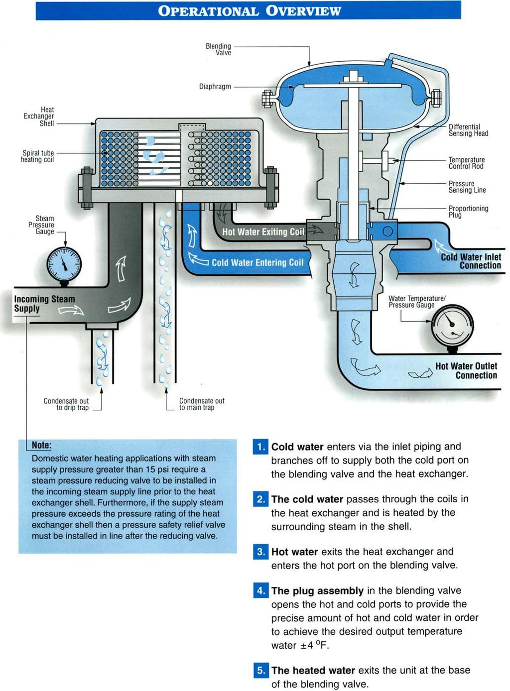
6 SECTION I - GENERAL DESCRIPTION AND CONSTRUCTION GENERAL DESCRIPTION This manual provides a complete description, as well as installation, operating, troubleshooting, maintenance and servicing procedures for an instantaneous steam powered water heater. This heater provides potable hot water for various functions. It is a permanently installed, stationary, self-contained unit with automatic operating controls. GENERAL OPERATION The F model operates using steam as its power source for heating potable hot water. Steam enters the heat exchanger shell where heat transfer takes place from the steam to the water. A helical coil with water flowing inside it is enclosed within the heat exchanger shell. As water flows through the coil, it is heated by the steam in the shell. After the heated water exits the coil it then enters the blending valve, which is comprised of three (3) separate ports: the cold water port, the hot water port, and the blended water port. After exiting the coil the heated water enters the hot water port of the blending valve. The blending valve then mixes the heated water with the cold water entering from the cold water port providing the precise amount of cold and hot water to produce the desired output temperature. This hot water then exits the heater through the hot water outlet. CONSTRUCTION STEAM HEATING COIL The water heater is supplied with a high quality Heliflow Heat Exchanger certified to ASME Section VIII Division 1 standards and constructed from single wall copper tubing. The tubing is installed in a heavyduty cast iron shell. Optionally, the tubing may be constructed from double wall tubing with a leak detection port (F30 and F60 models only), or alternate tubing materials may be used, such as Admiralty, 90/10 copper-nickel, or stainless steel. Additionally, as an option, the shell may also be constructed from cast steel, cast bronze, 90/10 copper-nickel, or stainless steel. STEAM OPERATING CONTROLS The steam operating controls are factory selected, sized, piped, and tested to ensure reliable operation. Blending Valve The blending valve mixes the heated water with the cold water entering from the cold water port providing the precise amount of cold and hot water to produce the desired output temperature. Strainers A cast iron Y strainer with 20 mesh screen protects the steam controls and coil from dirt and debris in the steam supply. Traps Two traps should be utilized in the immediate steam piping system of the water heater. The first trap in the system is a thermostatic drip trap that is designed to collect condensate from the main steam line before entering the control valve. Additionally, a main condensate cast iron float and thermostatic trap should be located in the condensate line after the steam coil. This trap ensures that the steam remains in the coil and releases its energy before exiting the coil and traveling down the condensate line. 6
 may be included.")
7 SUPPORT STAND The unit is supported on heavy-duty integrally welded steel supports for sturdy floor mounting. OPTIONS The following optional features may be included in your water heater. Reference included drawing specific to your heater for further details. Cast Steel Construction Optional cast steel construction of all steam components (traps, strainers) may be included. Single Solenoid Safety System A single solenoid safety system opens the sensing line to the blending valve in order to limit the hot water output in the event of an over-temperature condition. This option requires 120- volt, 5-amp electrical service. Double Solenoid Safety System A double solenoid safety system opens the sensing line to the blending valve as well as closing the steam supply to the heat exchanger in the event of an over-temperature condition. This option requires 120-volt, 5-amp electrical service. Steam Pressure Reducing Valve In order to limit the steam pressure in the heat exchanger shell an optional steam pressure reducing valve may be factory supplied and shipped loose for in the field installation. Klean-Koil Kit For applications where water hardness exceeds 120 ppm and scale build-up can reduce efficiency, a factory packaged Klean-Koil Kit may be supplied. This kit with built-in connections will allow for quick and easy in-place cleaning of the coil to remove deposits of scale and thereby avoid long periods of down time and expensive maintenance costs. Recirculation Package A recirculation loop is used to provide hot water at the fixture even though the water heater may be a great distance away. This loop usually continuously recirculates the water via a small pump that returns the water to the heater for boosting if required. Since the F Model heater does not have any sensing capability, the temperature of the water is unknown and likely to escalate. The recirculation package option therefore uses a 3-way thermostatic valve. The thermostatic valve has a thermal sensing element rated at the desired loop temperature. As the temperature in the loop begins to decrease from heat loss through the piping, the thermostatic element responds by causing the water flow to be diverted to the heater. When the temperature in the loop is at the desired temperature the flow of the water by-passes the heater. For normal operation, approximately 10% of the system capacity is recirculated back to the heater. Higher flows can induce high pressure differentials in the valve and cause erratic operation. 7
8 SECTION II INSTALLATION 1. The water heater is typically floor mounted, but can also be suspended from the ceiling. It is important that the unit is horizontal and level. 2. For optimal water heater performance the condensate trap should discharge to a condensate line which is atmospheric or sub-atmospheric in pressure, below the level of the trap. If lift of condensate is required, utilize the guidelines in the following table. Inlet Steam Pressure (PSIG) Maximum Elevation of Condensate Discharge (ft) Table 1 - Maximum Condensate Elevations 3. If the steam supply pressure to the water heater exceeds 75 psi then a pressure relief valve must be installed in the steam supply line immediately before the heat exchanger shell. If a pressure reducing valve is used to reduce the steam supply pressure, a pressure relief valve should still be installed. 4. The heater incorporates an integral safety relief valve to relieve excess pressure caused by thermal expansion. Be sure discharge is facing a safe direction. This device does not replace or eliminate the need for a separate pressure relief valve as described in paragraph 3 above. 5. Install the combination water temperature/pressure gauge in the hot water outlet piping, as close to the heater as possible. 6. Install the steam pressure gauge in the steam supply line, as close to the heater as possible. 7. Check and verify that the water supply pressure is 40 psig minimum. This is required for optimal operation. 8. Maximum steam pressure to the heater is typically 15 psig. Set pressure reducing valve, if required, to an output pressure of 15 psig or as specified. Note: some units used in applications with less stringent temperature requirements can operate above 15 psi without a pressure reducing valve, please reference the included drawing for details. 9. Check tightness of all connections. 8
9 F Model Piping Schematic 9

10 10 Parallel F Model Piping Schematic
11 SECTION III START-UP PROCEDURE 1. Check all joints for tightness. Remove protective shroud. 2. Note that for two or more units piped together, be sure to adjust all units simultaneously, as multiple units may cause unnecessary feedback. 3. If a recirculation package is included with your system, shut down flow to the recirculation package before beginning adjustment of the outlet temperature. 4. Turn on cold water supply. Set flow at midpoint of heater capacity, i.e. 15 GPM for a 30 GPM unit (minimum water pressure 40 psig, maximum pressure 150 psig). 5. Loosen compression fitting on upper diaphragm cover. Permit water to flow until free of any bubbles. Retighten fitting. 6. Turn on steam to heat exchanger. a. Vent air from heat exchanger by carefully loosening the vent plug in the top of the heat exchanger casing. b. Upon completion, retighten. c. Maximum steam pressure is typically 15 psig. See attached drawing for details. d. If unit is furnished with a pressure reducing valve, set reduced pressure to 15 psig maximum before adjusting the heater. e. Verify that condensate is properly drained. 7. On the blending valve loosen set screw and locking ring, enabling the control rod on the valve to move freely from right to left. The heater features a temperature stabilizer which will fine tune the proportion of hot and cold water in order to accurately produce hot water through all rated flows. The stabilization adjustment is performed by rotating the control rod from vertical to 30. Install a pin in the hole of the control rod and rotate to the approximate position as indicated in Table 2. Operate the heater from minimum to maximum flows. Position the control rod at the correct outlet temperature and note any variations in temperature from maximum to minimum flow. If the outlet temperature tends to increase with increased flow, the rotation of the stabilizer should be decreased (toward 0 ). Likewise, if the outlet temperature tends to decrease with increased flow, the rotation of the stabilizer should be increased (toward 30 ). Correct adjustment will yield stable temperature output throughout the heaters flow capacities. Once the correct adjustments have been made, tighten the locking ring and set screw. 8. If a recirculation package is included, shut down all hot water demand on the unit, open the valves to the recirculation loop, turn the valve adjustment screw to full cold position and wait until recirculation loop settles. Then increase the temperature of the recirculation loop by adjusting the thermostatic valve adjustment screw and allow the recirculation loop to settle. Continue adjustments in this manner until the desired recirculation temperature is reached. Note that the recirculation temperature must be at least 10 F below the desired outlet temperature. 9. Heater should now be adjusted and operating. No further adjustments are required, unless there is a large fluctuation in seasonal water temperatures. If this is the case, readjustment of the control rod will be necessary. If shutdown of the unit is necessary, close water and steam valves. To restart, open all valves and repeat start-up procedure. NOTE Every 3 F change in supply cold water temperature will yield a 1 F change in the outlet hot water temperature. 10. Tighten all casing bolts (87) on heat exchanger after 2-3 hours and check after 24 hours. Place protective shroud over the heat exchanger. 11
12 Inlet Water Temp. 40 F 60 F Table 2 Temperature Stabilization Adjustment Table (Approximate setting in degrees of rotation. See illustration below) Steam pressure measured at heat exchanger inlet Outlet F15/F30 F45/F60 Water Temp. 2 psi 5 psi 10 psi 15 psi 2 psi 5 psi 10 psi 15 psi 120 F F F F F F F F F F Inlet Water Temp. 40 F 60 F Outlet F75/F90 F105/F120 Water Temp. 2 psi 5 psi 10 psi 15 psi 2 psi 5 psi 10 psi 15 psi 120 F F F F F F F F F F Blending Valve 12
13 SECTION IV MAINTENANCE 1. BLENDING VALVE DISASSEMBLY Disassembly of the blending valve need only be undertaken if a decrease in performance or instability of temperature control is linked to malfunction or wear of control valve components. Be sure all work is performed in a clean environment to prevent the introduction of foreign matter into the valve mechanism. a. Close all steam and water supply lines. b. Disconnect sensing tube (46) from lower valve body (42) and lower diaphragm case (5). (Note position of notch in cover relative to valve body). c. Disconnect Victaulic fittings at all valve connections and remove the valve support clips from frame. Lift the entire blending valve from frame. d. Loosen and remove casing bolts (14) and lift off upper diaphragm case (6). e. Hold valve stem (1) by placing wrench on flats. Remove jam nuts (7) taking care not to turn valve stem (1). Remove shouldered washer (8) and "O" ring (9) along with diaphragm (13), diaphragm plate (11), control valve spring (10), and shoulder washer (16). f. Inspect diaphragm (13) for any cracks or tears. g. Remove stop retaining clip (19) from temperature control rod (18), unscrew locking ring assembly (21), and remove cover plate (22). h. Compress retaining "C" clip (23) and remove from temperature adjusting sleeve (27). Remove temperature control rod (18) and key cylinder (25) from stub. CAUTION Do not permit the plug assembly to drop from lower valve body (42). Hold valve stem (1) from above. i. Unscrew stem screw (35), remove the yielding spring (36), and spacer washers (37,38). j. Remove the valve plug assembly through the lower valve body (42). k. Remove socket head cap screws (12) and lift off lower diaphragm case (5). Remove "O" ring (15) taking care not to damage groove. l. Remove cap screws (12) and remove lower valve body (42). m. Push black Teflon coated temperature adjusting sleeve (27) out of upper valve body (17). n. Remove main valve stem (1). NOTE Inspect all parts for wear or damage. Replace all gaskets and "O" rings. CAUTION Do not use any abrasive to clean. Wipe with appropriate solvents and dry with clean cloth. (Acetone is a suitable solvent). NOTE See parts list for recommended on hand spare and overhaul parts. 2. BLENDING VALVE ASSEMBLY a. Install temperature adjusting sleeve (27) into upper valve body (17), making sure the end of the temperature adjusting sleeve (27) with the groove pins and slot is facing the lower valve body (42). b. Assemble upper valve body (17) to lower valve body (42) and (cold water inlet should be on same side as the control rod opening) secure cap screws (12). 13
14 14 c. Insert main valve stem (1) into bottom of temperature adjusting sleeve (27) and push it until the collar washer seats against upper valve body (17). d. Insert the valve assembly into temperature adjusting sleeve (27) and push until it is fully inserted. e. On lower end of valve stem (1) install spacer (2), space washers (37), space washer (38), yielding spring (36), and tighten stem screw (35). f. Install "O" ring (15) in groove on upper valve body (17) and install lower diaphragm case (5) securing it with casing bolts (14) tightening in a sequential manner (note location of notch in relation to valve body). g. Install key cylinder (25) on stub. Replace "O" ring (24) on temperature control rod (18) and insert so adjustor key is centered in slot and notch on control rod fits with groove pin in temperature adjusting sleeve (27). Install retaining "C" clip (23) and locking ring assembly (21). h. Install in order, the control valve spring (10), guide washer (16), diaphragm plate (11), diaphragm (13), "O" ring (9), shouldered washer (8), and jam nuts (7) on main valve stem (1). Position diaphragm (13) over holes and notch on lower diaphragm case (5) prior to tightening the jam nuts (7). i. Install upper diaphragm case (6) and be sure notches in lower cover and upper cover line up. Install bolts and tighten sequentially. j. Install valve on frame, install sensing tube (46) Victaulic fittings, and check all fittings for tightness. k. Refer to start-up procedures to adjust blending valve. 3. HEAT EXCHANGER INSPECTION AND DISASSEMBLY The Heliflow coil is readily accessible for inspection and cleaning, if necessary, without disturbing piping. a. Remove plug (85) to drain the casing assembly (79). b. Remove all base plate nuts (86). c. Withdraw the casing assembly (79), being careful not to damage the gasket (81). 4. REMOVAL OF COIL (IF NECESSARY) a. Disconnect piping and remove the manifold nuts (84) and lock rings (83). b. Withdraw the coil assembly (78), being careful not to damage the manifold gaskets (82). 5. HEAT EXCHANGER INSPECTION - REASSEMBLY a. In re-assembly, be sure manifold gaskets (82) and casing gaskets (81) are replaced. b. Be sure that tabs on the manifold lock rings (83) fit into the base plate slots. These keep the coil assembly (78) from turning when tightening the manifold nuts (84) and piping to the unit. c. Be sure the bottoms of the manifold gaskets (82) are seated in pockets located at bottom inside the casing assembly (79). d. Install and tighten manifold nuts (84). e. Install casing (79) and tighten base plate nuts (86) sequentially. f. Vent the casing (79) when re-admitting fluid, using drain plug (85). g. Check base plate nut (86) tightness after an hour or two, and again after 24 hours. 6. STRAINER FILTER (next page) Clean strainer filter. Perform annually or more often, if required. a. Remove blowoff bushing (E) or cap (F), as required. b. Remove gasket (B), if required. c. Remove, clean, and re-install screen (A). d. Replace gasket (B). e. Re-install blowoff bushing (E) or cap (F), as required.
15 Blending Valve Parts Diagram 15
16 16 Heat Exchanger Parts Diagram
17 Item No. Blending Valve and Heat Exchanger Parts List Use only genuine Hubbell Replacement Parts * - Recommended Spare Parts ** - Overhaul Parts in Addition to Spares Description Part Numbers F15/F30 F45/F60 F75/F90 F105/F120 VALVE STEM 1 Valve Stem Spacer (2) Spacer (Teflon) Spirolox Ring 60003* 60003* 60003* 60003* DIAPHRAGM 5 Lower Case Upper Case Jam Nut Shouldered Washer O Ring 60019* 60019* 60019* 60019* 10 Spring Diaphragm Plate S/S Cap Screw (6) Diaphragm 60045* 60045* 60045* 60045* 14 Bolt (6) A Nut (6) O Ring Shoulder Washer ADJUSTER 17 Upper Valve Body Control Rod 60009** 60009** 60312** 60312** 19 Retaining Clip 60050* 60050* 60050* 60050* 20 Set Screw Locking Ring Plate (Cover) Retaining C Clip 60049* 60049* 60049* 60049* 24 O Ring (2) Key Cylinder O Ring (2) 60027* 60027* Temperature Adjusting Sleeve ** 60318** 28 Guide Energizer 60025** 60025** 60025** 60025** PLUG ASSEMBLY 31 Plug Stem ** 60321** 32 Pin Plug Stem Plug Pin Plug Stem Screw Yielding Spring 60039** 60039** 60323** 60323** 37 S/S Spacer Washer (2) Brass Spacer Washer Seal Plate 60012** 60012** 60315** 60315** 40 Screw (2) Lock Washer (2)
18 Item No. Description Part Numbers F15/F30 F45/F60 F75/F90 F105/F120 LOWER VALVE BODY 42 Valve Body Relief Valve Sensing Tube Outlet Adapter Victaulic Coupling Screw (6) HEAT EXCHANGER 78 Coil Assembly (Copper Tubes) 72916B* 72922A* * * 79 Casing (Upper) A Base Plate Casing Gasket 51215* 51216* 51216* 51217* 82 Manifold Gasket 20211* 20212* 20212* 20213* 83 Lockring * 84 Manifold Nut 23014A Drain Plug Nut (13, 12 for F30) Stud Bolt (13, 12 for F30) The following part numbers (P/N) were changed as follows as of Dec. 2008: P/N was superseded by P/N P/N was superseded by P/N P/N was superseded by P/N P/N was superseded by P/N P/N was superseded by P/N P/N was superseded by P/N P/N was superseded by P/N P/N was superseded by P/N The following part numbers (P/N) were changed as follows as of Jan. 2010: P/N was superseded by P/N P/N was superseded by P/N
19 Single and Double Safety Solenoid System (if installed) 19
20 7. INSTRUCTION FOR CHEMICAL CLEANING a. Shut off both water inlet and outlet on coil to be cleaned. b. Remove the two elbow manifolds from the heat exchanger, by disassembling the four Victaulic couplings. c. Attach the 3/8 nipple supplied with the adaptor kit to one of the adaptors. d. Insert this adaptor into the heater connection closest to the center of the exchanger. (Note: The 3/8 nipple must extend up into the exchanger). Secure the adaptor with one of the Victaulic couplings removed in Step a. e. Connect the other adaptor to the remaining exchanger connection with a Victaulic coupling. f. Connect the recirculation pump, hoses, and reservoir tank. g. Clean unit with de-scaling solution according to directions included with descaler. h. For proper cleaning, the solution must be pumped through the exchanger in the direction shown in the figure below. The 3/8 nipple avoids gas pockets in the top of the exchanger coil and must be on the outlet connection of the cleaning system. i. After cleaning is complete, the coil should be flushed with water before reconnecting the manifolds. 20 SECTION V TROUBLESHOOTING Observations regarding any problems should be recorded. 1. Does the problem present itself during no flow, low flow, or high flow conditions, etc? 2. High temperature or low temperature? Note the F model is designed to prevent high temperature failures, however, recirculation system failures may lead to overtemperature situations during low flow conditions. 3. Unsteady temperature? 4. Is the new or what is length of service? 5. What is local water hardness?
21 6. Is the problem repeatable, sporadic? The first step in resolving a problem with an F model water heater system should be to determine the source of the problem. The recirculation system The blending valve The heat exchanger 1. Check the position of the water outlet temperature gauge. Has it been installed according to the recommended Piping & Instrumentation Diagram? The gauge should be downstream relative to the point where the recirculated water returns to the unit. 2. For facilities with recirculation systems, the circulating pump should be turned off to start the troubleshooting analysis. Water Temperature Is Too High 1. Has inlet water temperature changed since the valve temperature setting was adjusted? 2. Is the F model temperature adjustment set correctly? 3. Has steam pressure changed since the temperature was adjusted? 4. If fitted with a recirculation system, turn the circulating pump off. If the problem is eliminated, the trouble is with the recirculation system. For a new installation with a recirculation loop, check the setting of the thermostatic valve. The thermostatic element setting should be approximately 10 F below the normal operating temperature of the F model. For example, if 120 F is the desired loop temperature, the thermostatic element should be set for 110 F. Also for new installations, check that the thermostatic diverting valve has been piped in accordance with the Hubbell Recirculation Package Diagram in this manual. If the problem developed in an existing system, the thermostatic element should be replaced. Water Temperature Is Too Low 1. Is the problem in the F model valve or the heat exchanger? The easiest method to answer this question is to check the temperature of the pipe which runs from the heat exchanger to the blending valve. At low flows and when the unit is idle, this pipe should be at a temperature about 200 F. At higher flow rates, check the surface temperature of the pipe which should remain above 150 F. If this pipe goes cold when water demand increases, the problem lies in the heat exchanger. Otherwise, the source of the problem is in the blending valve. Heat Exchanger Is Source of Problem 1. Has air been vented from the shell side of the heat exchanger? 2. Is steam supply at constant pressure? During high demand? 3. Is the condensate drain trap functioning correctly? 4. Is the coil fouled due to hard water? Blending Valve Is Source of Problem 1. Is temperature adjustment correct? 2. Disassemble valve is the plug stuck in the open position? 3. Is the seal plate assembly and gasket in need of repair? Restricted Water Flow 1. Is the valve diaphragm ruptured? 2. Is the sensing tube plugged? 3. Are there any restrictions in the water piping? 21
22 Symptom Probable Cause Corrective Action / Remedy Unit produces only cold water or no water flow at all. Diaphragm ruptured. Remove upper cover and inspect for tears or cracks, replace as necessary. Valve plug restricted by Remove plug and clean. foreign matter. Sensing line restricted. Remove and test for free flow. Drop in output temperature occurring during low flow. Trap failure. Remove and test. Steam pressure incorrect. Check inlet pressure to heat exchanger. Outlet water temperature Reset. setting incorrect. Stabilization setting incorrect. Reset. Trap restricted or Check piping for free flow. experiencing excessive back Remove and inspect trap. pressure. Steam strainers plugged. Clean strainers. Rise in output temperature occurring during low flow. Low steam pressure to heat exchanger. Drop in water temperature occurring before capacity of heater is achieved. Erratic changes in outlet temperature during no flow conditions with a recirculation package installed. Air lock in heat exchanger Vent exchanger. shell. Steam pressure incorrect. Check inlet pressure to heat exchanger. Water supply pressure drop Check and correct. below 40 psig. Heater reset with fouled coils. Remove coil and clean or replace. Inlet water temperature too Check water temperature. high. Steam strainers severely Clean screens. plugged or restricted. Pressure reducing valve not Reset per manufacturer s set correctly. instruction. Incorrect steam pressure to Test and adjust. heater. Water pressure below 40 psig. Check and adjust (maximum pressure 150 psig). Safety seal plate leaking. Remove valve plug and replace plate. Trap restricted or Check piping for free flow. experiencing excessive back Remove and inspect trap. pressure. Steam pressure incorrect or steam or condensate piping not sufficient size. Improper adjustment of the recirculation thermostatic valve. Check steam pressure at exchanger. Check for correct pipe diameter on steam and condensate lines. Check steam strainers for blockage. Check and correct. 22
23 SECTION VI MISCELLANEOUS CHARTS AND FORMULAS TORQUE VALUES BOLT SIZE 18-8 S/S IN.-LBS. BRASS IN.-LBS. SILICON BRONZE IN.-LBS. ALUMINUM 2024-T4 IN.-LBS. 316 S/S IN.-LBS. MONEL IN.-LBS / / / / / / / / / / / / / / / / / / METRIC CONVERSIONS 23
24 24 P.O. BOX 288 STRATFORD, CT PHONE: (203) FAX: (203) INTERNET:
High Capacity Instantaneous Steam Fired Water Heater
 MODEL F High Capacity Instantaneous Steam Fired Water Heater Features Compact High Capacity Design Packaged System Water heater is factory assembled on an all welded steel mounting frame to save time and
OPERATING AND MAINTENANCE MANUAL FOR PLATE HEAT EXCHANGER INDIRECT FIRED WATER HEATER. Electric Heater Company Base Model "BWXP"
 OPERATING AND MAINTENANCE MANUAL FOR PLATE HEAT EXCHANGER INDIRECT FIRED WATER HEATER Electric Heater Company Base Model "BWXP" HUBBELL ELECTRIC HEATER COMPANY P.O. BOX 288 STRATFORD, CT 06615 PHONE: (203)
INSTALLATION AND MAINTENANCE INSTRUCTIONS. IM US March RediHeat. Table Of Contents. I. Installation RediHeat Start-Up Procedure 4
 INSTALLATION AND MAINTENANCE INSTRUCTIONS IM-12-002-US March 2018 RediHeat Table Of Contents Page I. Installation 2. RediHeat Start-Up Procedure 2.1 Initial start-up 2.2 RH-30/60 temperature stabilization
INSTALLATION, OPERATION AND MAINTENANCE MANUAL FOR COMMERCIAL INDIRECT POWERED WATER HEATER
 INSTALLATION, OPERATION AND MAINTENANCE MANUAL FOR COMMERCIAL INDIRECT POWERED WATER HEATER ELECTRIC HEATER COMPANY BASE MODEL T Edition 0 HUBBELL ELECTRIC HEATER COMPANY P.O. BOX 88 STRATFORD, CT 0665
OPERATING AND MAINTENANCE MANUAL FOR ELECTRIC STAINLESS STEEL HEATER FOR DEIONIZED (DI) WATER ELECTRIC HEATER COMPANY BASE MODEL D
 WATER ELECTRIC HEATER COMPANY BASE MODEL D") OPERATING AND MAINTENANCE MANUAL FOR ELECTRIC STAINLESS STEEL HEATER FOR DEIONIZED (DI) WATER ELECTRIC HEATER COMPANY BASE MODEL D HUBBELL ELECTRIC HEATER COMPANY P.O. BOX 288 STRATFORD, CT 06615 PHONE:
OPERATING AND MAINTENANCE MANUAL FOR ELECTRIC STAINLESS STEEL HEATER FOR DEIONIZED (DI) WATER ELECTRIC HEATER COMPANY BASE MODEL D HUBBELL ELECTRIC HEATER COMPANY P.O. BOX 288 STRATFORD, CT 06615 PHONE:
Packaged Semi-Instantaneous Steam Fired Water Heater
 MODEL STX Packaged Semi-Instantaneous Steam Fired Water Heater Shell and Tube Style Heater Features Reliable Only high grade materials used in construction to ensure long operating life Heat exchange pressure
Technical Data TYPE T14 & T14D TEMPERATURE PILOT SPENCE ENGINEERING COMPANY, INC. 150 COLDENHAM ROAD, WALDEN, NY SD 4511A T14 PILOT
 Technical Data SD 4511A SPENCE ENGINEERING COMPANY, INC. 150 COLDENHAM ROAD, WALDEN, NY 12586-2035 TYPE T14 & T14D TEMPERATURE PILOT PRINTED IN U.S.A. SD 4511A/9811 5 13 /16 D 4 7 /8 1 13 /16 T14 PILOT
OPERATING AND MAINTENANCE MANUAL FOR STEAM FIRED WATER HEATER. ELECTRIC HEATER COMPANY BASE MODEL ST and STH
 OPERATING AND MAINTENANCE MANUAL FOR STEAM FIRED WATER HEATER ELECTRIC HEATER COMPANY BASE MODEL ST and STH HUBBELL ELECTRIC HEATER COMPANY P.O. BOX 288 STRATFORD, CT 06615 PHONE: (203) 378-2659 FAX: (203)
INSTALLATION, OPERATION AND MAINTENANCE MANUAL FOR POINT OF USE STEAM FIRED WATER HEATER ELECTRIC HEATER COMPANY BASE MODEL PS
 INSTALLATION, OPERATION AND MAINTENANCE MANUAL FOR POINT OF USE STEAM FIRED WATER HEATER ELECTRIC HEATER COMPANY BASE MODEL PS Edition 2011 HUBBELL ELECTRIC HEATER COMPANY P.O. BOX 288 STRATFORD, CT 06615
FLO-RITE-TEMP INSTANTANEOUS WATER HEATER INSTALLATION AND ADJUSTMENT INSTRUCTIONS FOR SINGLE AND DOUBLE WALL UNITS
 FLO-RITE-TEMP INSTANTANEOUS WATER HEATER INSTALLATION AND ADJUSTMENT INSTRUCTIONS FOR SINGLE AND DOUBLE WALL UNITS Bulletin No. AY-780-L This bulletin should be used by experienced personnel as a guide
OPERATING AND MAINTENANCE MANUAL FOR BOILER WATER OR HIGH TEMPERATURE HOT WATER (HTHW) POWERED WATER HEATER
 POWERED WATER HEATER") OPERATING AND MAINTENANCE MANUAL FOR BOILER WATER OR HIGH TEMPERATURE HOT WATER (HTHW) POWERED WATER HEATER ELECTRIC HEATER COMPANY BASE MODEL BW and BWH HUBBELL ELECTRIC HEATER COMPANY P.O. BOX 288 STRATFORD,
OPERATING AND MAINTENANCE MANUAL FOR BOILER WATER OR HIGH TEMPERATURE HOT WATER (HTHW) POWERED WATER HEATER ELECTRIC HEATER COMPANY BASE MODEL BW and BWH HUBBELL ELECTRIC HEATER COMPANY P.O. BOX 288 STRATFORD,
SuperKlean Washdown Products
 February 2012 DURAMIX 8000 INSTALLATION AND MAINTENANCE INSTRUCTIONS **DO NOT THROW AWAY AFTER INSTALLATION** **SAVE AND DISPLAY PROMINENTLY WHERE THIS EQUIPMENT IS USED** WARNING HIGH PRESSURE AND HOT
Instant hot water Feed-Forward system unlimited supply accurate to +/- 4 F
 Count on Graham for proven reliability. Graham is one of the world s foremost designers and manufacturers of vacuum and heat transfer equipment with over a half-century of proven experience. Our in-house
Series 1140 and 1141 Temperature Regulators
 Hoffman Specialty Installation & Maintenance Instructions HS-504(E) Series 1140 and 1141 Temperature Regulators! CAUTION FOLLOW ALL INSTALLATION AND OPERATING INSTRUCTIONS. TURN OFF WATER OR STEAM BEFORE
Semi-Instantaneous Indirect Fired Water Heater
 MODEL BWX Semi-Instantaneous Indirect Fired Water Heater Use Boiler Water Or HTHW To Heat Domestic Water Features Reliable Only high grade materials used in construction to ensure long operating life Hydrastone
13-1. Temperature Regulator
 -1 Step 0 Type/Structure/Features Please refer to this for type, structure and features of. Step 1 Selection Please look at the ID chart to choose the right products depending on the intended uses. Details
Audi-Larm Audible Alarm
 Audi-Larm Audible Alarm MAINTENANCE AND REPAIR TAL 1706 (L) Rev. 7 MSA 2017 Prnt. Spec. 10000005389(I) Mat. 10093084 Doc. 10093084 REPLACEMENT KITS AND PARTS LIST TAL 1706 (L) Rev. 7-10093084 2 Exploded
Packaged Steam Fired Water Heater
 MODEL ST Packaged Steam Fired Water Heater Utilizes Steam To Heat Domestic Water, Semi-Instantaneous or Storage Type Heaters Features Reliable Packaged System Only high grade materials used in construction
OPERATING AND MAINTENANCE MANUAL FOR COMMERCIAL ELECTRIC WATER HEATER. ELECTRIC HEATER COMPANY BASE MODEL SH and H
 OPERATING AND MAINTENANCE MANUAL FOR COMMERCIAL ELECTRIC WATER HEATER ELECTRIC HEATER COMPANY BASE MODEL SH and H HUBBELL ELECTRIC HEATER COMPANY P.O. BOX 288 STRATFORD, CT 06615 PHONE: (203) 378-2659
INSTALLATION & MAINTENANCE MANUAL FOR QuickDraw
 INSTALLATION & MAINTENANCE MANUAL FOR QuickDraw SEMI-INSTANTANEOUS ENERGY: STEAM TO WATER U-TUBE SINGLE-WALL & DOUBLE-WALL HEAT EXCHANGERS FLOOR DRAIN Typical Construction Figure 34-1 FLOOR DRAIN 1. U-tube
Niles Steel Tank Hot Water Generator Installation and Operation Manual
 Niles Steel Tank Hot Water Generator Installation and Operation Manual Contents: Contents 1 Hazard definitions 1 1. General Information.... 2 Availability... 3 Optional Control Packages... 5 2. Installation....
Crown Boiler Company
 Crown Boiler Company 1 Phantom Boiler System Combi Kit Instruction Manual I Product Description This kit adds the ability to generate DHW, as well as heat, ( combi capability) to select Phantom models
J120 STEAM BOOSTER INSTALLATION, OPERATION, AND SERVICE MANUAL J120 STEAM BOOSTER. J120 Steam Booster Manual D
 INSTALLATION, OPERATION, AND SERVICE MANUAL J120 STEAM BOOSTER J120 STEAM BOOSTER J120 Steam Booster Manual REVISION HISTORY Revision Letter Revision Date Made by Applicable ECNs Details A 10-27-04 CBW
Installation S
 Installation S59-2025 Thermostatic Mixing Valve (TMV25) with Optional Cabinet S59-2025RE (with Recess-Mounted Enamel Cabinet) S59-2025RS (with Recess-Mounted Stainless Steel Cabinet) S59-2025SE (with Surface-Mounted
Page 1 of 18. Part# /5/2013
 Part# 1002655-06 8/5/2013 This manual contains important information concerning the installation and operation of the gun washers listed above. Read manual thoroughly and keep for future reference INSTRUCTIONS
Installation S
 Installation S59-3080 Thermostatic Mixing Valve with Optional Cabinet S59-3080RE (with Recess-Mounted Enamel Cabinet) S59-3080RS (with Recess-Mounted Stainless Steel Cabinet) S59-3080SE (with Surface-
FFH Series. Steam Fired Instantaneous Feed Forward Water Heaters
 FFH Series Steam Fired Instantaneous Feed Forward Water Heaters CEMLINE CORPORATION P.O. BOX 55 CHESWICK, PENNSYLVANIA 15024 Phone: (724) 274-5430 FAX: (724) 274-5448 www.cemline.com Operation of Cemline
Indirect Fired Water Heater
 Indirect Fired Water Heater 35-119 Gallon Capacities Features Heavy Duty Construction Hydrastone cement lining provides long tank life Copper-silicon tappings cannot rust or corrode High impact composite
SERVICE MANUAL. Bradford White ElectriFLEX HD (Heavy Duty) Commercial Electric Water Heater CEHD SERIES Immersion Thermostat Models
 Commercial Electric Water Heater CEHD SERIES Immersion Thermostat Models") Bradford White ElectriFLEX HD (Heavy Duty) Commercial Electric Water Heater CEHD SERIES Immersion Thermostat Models SERVICE MANUAL Troubleshooting Guide and Instructions for Service (To be performed ONLY
Bradford White ElectriFLEX HD (Heavy Duty) Commercial Electric Water Heater CEHD SERIES Immersion Thermostat Models SERVICE MANUAL Troubleshooting Guide and Instructions for Service (To be performed ONLY
Flo-Rite-Temp Installation and Operation Manual IOM-780-N
 Flo-Rite-Temp Installation and Operation Manual IOM-780-N Table of Contents Introduction...3 Steam Piping Installation...10 Water Piping Installation...11 Pressure Relief (Pop-Off Value) Installation...12
Wallace & Tiernan Gas Feed Systems V2000 Chlorinator
 Wallace & Tiernan Gas Feed Systems V2000 Chlorinator Introduction Siemens Water Technologies chlorination equipment has the benefit of 100 years of experience in gas feed technology. V2000 chlorinators
Installation S
 Installation S59-3045 Thermostatic High-Low Mixing Valve (HL45) with Optional Cabinet S59-3045 (Valve Only) S59-3045RE (with Recess-Mounted Enamel Cabinet) S59-3045RS (with Recess-Mounted Stainless Steel
Installation S
 Installation S59-3200 Thermostatic Mixing Valve (HL200) with Optional Cabinet S59-3200RE (with Recess-Mounted Enamel Cabinet) S59-3200RS (with Recess-Mounted Stainless Steel Cabinet) S59-3200SE (with Surface-Mounted
Installation S
 Installation S59-3080 Thermostatic High-Low Mixing Valve (HL80) with Optional Cabinet S59-3080RE (with Recess-Mounted Enamel Cabinet) S59-3080RS (with Recess-Mounted Stainless Steel Cabinet) S59-3080SE
ECOJET EJ-10E & EJ-7E ELECTRIC CONVECTION STEAMER W/TWIN GENERATORS PARTS AND SERVICE MANUAL
 ECOJET EJ-10E & EJ-7E ELECTRIC CONVECTION STEAMER W/TWIN GENERATORS PARTS AND SERVICE MANUAL EFFECTIVE JULY 31, 2014 Superseding All Previous Parts Lists. The Company reserves the right to make substitution
Thermostatic mixing valves with interchangeable cartridges
 www.caleffi.com R37. Thermostatic mixing valves with interchangeable cartridges Installation, commissioning and servicing instructions 3 Series Function The thermostatic mixing valve is used in systems
Packaged Instantaneous Circulation Heater Full KW Selection In All Voltages, Single or Three Phase
 Features Heavy Duty Construction Constructed with high grade materials to ensure long operating life Turn-Key package is simple to specify and operate Factory wired electrical controls provide trouble-free
TECHNICAL INSTRUCTIONS
 TID-0004_0A TECHNICAL INSTRUCTIONS Hardware Procedure: Coil and Riser Replacement Procedures for All Styles of A, B, C, and D Indirect-Fired Water Heaters Applies to: Indirect-Fire Water Heaters. Description
TECHNICAL DATA OBSOLETE
 October 10, 2008 Deluge Devices 281a 1. PRODUCT DESCRIPTION The Viking Model C-1 is a rate-of-rise releasing device for use on hydraulic and pneumatic release systems controlling operation of Viking deluge
Instructions for Installation, Operation, Care and Maintenance
 Bulletin 422 Model E Alarm Check Valve Bulletin 422 Instructions for Installation, Operation, Care and Maintenance DN100, DN150, DN200 SIZE Model E with E2 Euro Trim The Reliable Automatic Sprinkler Co.,
TECHNICAL DATA. Wet 26a. February 22, 2009
 February 22, 2009 Wet 26a 1. DESCRIPTION The Viking Alarm Check Valve serves as a check valve by trapping pressurized water above the clapper and preventing reverse flow from sprinkler piping. The valve
INSTALLATION, OPERATING & MAINTENANCE INSTRUCTIONS FOR 350 SERIES CIRCULATION HEATERS
 INDEECO Circulation Heaters are designed to provide years of trouble free operation if properly installed and maintained. Please read and follow these instructions for installing and maintaining the heater.
MEGATRON MODEL 2, 3, 4, and 5
 MEGATRON MODEL 2, 3, 4, and 5 BULLETIN M-1020A 2/02 INSTALLATION ADJUSTMENT SERVICE COMPLETE WATER TEMPERATURE CONTROL STATION DOMESTIC OUTLET TEST/SETUP CONNETION RETURN LINE FROM BUILDING RETURN LINE
PS-3E AND PS-6E ELECTRIC CONVECTON STEAMERS PARTS AND SERVICE MANUAL
 PS-3E AND PS-6E ELECTRIC CONVECTON STEAMERS PARTS AND SERVICE MANUAL EFFECTIVE AUGUST 1, 2014 Superseding All Previous Parts Lists. The Company reserves the right to make substitution in the event that
3500 SERIES CONVECTION STEAM COOKER PARTS AND SERVICE MANUAL
 3500 SERIES CONVECTION STEAM COOKER PARTS AND SERVICE MANUAL EFFECTIVE JULY 30, 2014 Superseding All Previous Parts Lists. The Company reserves the right to make substitution in the event that items specified
TECHNICAL DATA. model c-2
 Page 1 of 6 1. PRODUCT DESCRIPTION The Viking Model C-2 is a rate-of-rise releasing device for use on hydraulic and pneumatic release systems controlling operation of Viking deluge valves on deluge or
SECTION (15486) - FUEL-FIRED, DOMESTIC WATER HEATERS
 - FUEL-FIRED, DOMESTIC WATER HEATERS") SECTION 22 34 00 (15486) - FUEL-FIRED, DOMESTIC WATER HEATERS System shall provide a complete hot water return throughout the entire system with balancing (flow control) valves not less than 10 feet from
SECTION 22 34 00 (15486) - FUEL-FIRED, DOMESTIC WATER HEATERS System shall provide a complete hot water return throughout the entire system with balancing (flow control) valves not less than 10 feet from
OPERATING AND MAINTENANCE MANUAL FOR PACKAGED ELECTRIC TEPID WATER HEATING SYSTEMS BASE MODEL ESS
 OPERATING AND MAINTENANCE MANUAL FOR PACKAGED ELECTRIC TEPID WATER HEATING SYSTEMS BASE MODEL ESS THERM-OMEGA-TECH, INC. 353 IVYLAND RD, WARMINSTER, PA 18974 PHONE: (877) 379-8258 INTERNET: http://www.thermomegatech.com
OPERATING INSTRUCTIONS MANUAL (Please retain for future reference) FVO-200 INDIRECT FIRED SPACE HEATERS
 FVO-200 INDIRECT FIRED SPACE HEATERS") OPERATING INSTRUCTIONS MANUAL (Please retain for future reference) For FVO-200 INDIRECT FIRED SPACE HEATERS CERTIFIED FOR USE IN CANADA AND U.S.A. As per CSA B140.8 Portable Oil Fired Heaters / CSA B140.02003
OPERATING INSTRUCTIONS MANUAL (Please retain for future reference) For FVO-200 INDIRECT FIRED SPACE HEATERS CERTIFIED FOR USE IN CANADA AND U.S.A. As per CSA B140.8 Portable Oil Fired Heaters / CSA B140.02003
Patterson/AMT Inline Circulator Pump Refer to pump manual for General Operating and Safety Instructions.
 Please read and save this Repair Parts Manual. Read this manual and the General Operating Instructions carefully before attempting to assemble, install, operate or maintain the product described. Protect
568X, 587X, 588X Series
 Please read and save this Repair Parts Manual. Read this manual and the General Operating Instructions carefully before attempting to assemble, install, operate or maintain the product described. Protect
5231 Series. Low Lead High Flow Thermostatic Mixing Valves. Installation, commissioning and service instructions ASSE 1017 NA10341
 NA31 www.caleffi.com Low Lead High Flow Thermostatic Mixing Valves Copyright 1 Caleffi Installation, commissioning and service instructions Function 531 Series ASSE 17 model 531 series high flow thermostatic
OPERATING AND MAINTENANCE MANUAL FOR VERTICAL IMMERSION HEATED STEAM BOILERS. Technical Control Systems Limited MODELS "VIHS"
 OPERATING AND MAINTENANCE MANUAL FOR VERTICAL IMMERSION HEATED STEAM BOILERS Technical Control Systems Limited MODELS "VIHS" Technical Control Systems Ltd Treefield Industrial Estate Gildersome, Leeds
5231 Series. Low Lead High Flow Thermostatic Mixing Valves. Installation, commissioning and service instructions ASSE 1017 NA10341.
 NA3. www.caleffi.com Low Lead High Flow Thermostatic Mixing Valves Copyright 5 Caleffi Installation, commissioning and service instructions Function 53 Series ASSE 7 model 53 series high fl ow thermostatic
! WARNING. Before using product, read and understand instructions.
 McDonnell & Miller Installation & Maintenance Instructions MM-607(B) Series FS7-4 Industrial Liquid Flow Switch (specified models only) Series FS7-4 OPERATION This control is an independently mounted water
OPERATING INSTRUCTIONS MANUAL (Please retain for future reference) FVO-400 INDIRECT FIRED SPACE HEATERS
 FVO-400 INDIRECT FIRED SPACE HEATERS") OPERATING INSTRUCTIONS MANUAL (Please retain for future reference) For FVO-400 INDIRECT FIRED SPACE HEATERS CERTIFIED FOR USE IN CANADA AND U.S.A. As per CSA B140.8 Portable Oil Fired Heaters / CSA B140.02003
OPERATING INSTRUCTIONS MANUAL (Please retain for future reference) For FVO-400 INDIRECT FIRED SPACE HEATERS CERTIFIED FOR USE IN CANADA AND U.S.A. As per CSA B140.8 Portable Oil Fired Heaters / CSA B140.02003
521 Series. MixCal adjustable three-way thermostatic mixing valve. Installation, commissioning and service instructions
 MixCal adjustable three-way thermostatic mixing valve 37. www.caleffi.com Copyright 15 Caleffi 51 Series Installation, commissioning and service instructions Function The Caleffi MixCal three-way thermostatic
IMAGE V. Parts and Service Manual
 IMAGE 0V Section II Parts and Service Manual (88B) CLARKE TECHNOLOGY Image Operator's Manual Page AUTHORIZED PERSONNEL MAINTENANCE To Access Pump Motor. Remove brush housing from machine. See "Brush Motor
ASME Packaged Indirect Fired Water Heater
 Features Reliable Only high grade materials used in construction to ensure long operating life Hydrastone cement lining provides superior protection and tank longevity Heavy duty construction withstands
Design and Construction Standards SECTION PLUMBING EQUIPMENT
 SECTION 15450 PLUMBING EQUIPMENT PART 1 GENERAL 1.1 SECTION INCLUDES: A. Water heaters. B. Packaged water heating systems. C. Water storage tanks. D. Water softeners. E. Pumps. F. Circulators. 1.2 REFERENCES
OPERATING INSTRUCTIONS MANUAL (Please retain for future reference) FVO-200 INDIRECT FIRED SPACE HEATERS
 FVO-200 INDIRECT FIRED SPACE HEATERS") OPERATING INSTRUCTIONS MANUAL (Please retain for future reference) For FVO-200 INDIRECT FIRED SPACE HEATERS CERTIFIED FOR USE IN CANADA AND U.S.A. As per CSA B140.8 Portable Oil Fired Heaters / CSA B140.02003
OPERATING INSTRUCTIONS MANUAL (Please retain for future reference) For FVO-200 INDIRECT FIRED SPACE HEATERS CERTIFIED FOR USE IN CANADA AND U.S.A. As per CSA B140.8 Portable Oil Fired Heaters / CSA B140.02003
SECTION PLUMBING EQUIPMENT
 PART 1 GENERAL 1.1 SECTION INCLUDES A. Water heaters B. Packaged water heating systems C. Water storage tanks D. Water softeners E. Pumps F. Circulators 1.2 REFERENCES SECTION 22 30 00 PLUMBING EQUIPMENT
Installation, Operation and Maintenance Guide G3600 Series Thermostatic Mixing Valves
 Note: Please provide valve serial number (stamped on cover of valve) when ordering parts. Tempered Water Outlet Cold Water Thermometer Hot Water Inline Check Redundant Thermostatic Mixing Valve Angle Checkstops
SECTION DOMESTIC WATER PIPING SPECIALTIES
 SECTION 22 11 19 DOMESTIC WATER PIPING SPECIALTIES PART 1 - GENERAL 1.1 RELATED DOCUMENTS A. Drawings and general provisions of the Contract, including General and Supplementary Conditions and Division
OPERATING INSTRUCTIONS MANUAL (Please retain for future reference) FVN/P-400 INDIRECT FIRED SPACE HEATERS
 FVN/P-400 INDIRECT FIRED SPACE HEATERS") OPERATING INSTRUCTIONS MANUAL (Please retain for future reference) For FVN/P-400 INDIRECT FIRED SPACE HEATERS CERTIFIED FOR USE IN CANADA AND U.S.A. As per Standard ANSI Z83.7/CSA 21.4 2000 Gas Fired Construction
OPERATING INSTRUCTIONS MANUAL (Please retain for future reference) For FVN/P-400 INDIRECT FIRED SPACE HEATERS CERTIFIED FOR USE IN CANADA AND U.S.A. As per Standard ANSI Z83.7/CSA 21.4 2000 Gas Fired Construction
Armstrong J Series Float, Thermostatic Steam Traps, Condensate Controllers & Liquid Drainers Installation and Maintenance Manual
 Armstrong J Series, Thermostatic Steam Traps, Condensate Controllers & Liquid Drainers Installation and Maintenance Manual This bulletin should be used by experienced personnel as a guide to the installation
Instruction Manual - Anti-Siphon Ejector Chlorine & Sulfur Dioxide 500 PPD (10 kg/h) Maximum Capacity
 Maximum Capacity") - Anti-Siphon Ejector Chlorine & Sulfur Dioxide 500 PPD (10 kg/h) Maximum Capacity 100 PPD (2 kg/h) Chlorine or Sulfur Dioxide 250 & 500 PPD (5 & 10 kg/h) Chlorine or Sulfur Dioxide Anti-Siphon Ejector
- Anti-Siphon Ejector Chlorine & Sulfur Dioxide 500 PPD (10 kg/h) Maximum Capacity 100 PPD (2 kg/h) Chlorine or Sulfur Dioxide 250 & 500 PPD (5 & 10 kg/h) Chlorine or Sulfur Dioxide Anti-Siphon Ejector
TEMPERATURE CONTROLLERS
 Instruction Manual: H1 T-12 Thermostat PILOT GUARD INTRODUCTION: SCOPE: This instruction manual includes installation, operation, and parts information for the Kimray Thermostat and Pilot Guard. Refer
Installation, Operation and Maintenance Guide AP3900 Series Thermostatic Mixing Valves
 Note: Please provide valve serial number (stamped on cover of valve) when ordering parts. Hot Water Tempered Water Outlet Cold Water Tempered Water Outlet Redundant Thermostatic Mixing Valve Hot Water
Tepid Water Delivery System
 Provides Tepid Water For Emergency Fixtures Features Heavy Duty Construction Hydrastone cement lining provides tank longevity Copper-silicon alloy tappings cannot rust or corrode High impact composite
B.I.C.A Built-In Coffee Appliance
 B.I.C.A Built-In Coffee Appliance Automatic Coffee Brewer Parts & Service Models: 1033510, 1033510S & 1033511 3828 S. Main St. Los Angeles, CA 90037-1491 800-421-6860 310-787-5444 Fax 310-787-5412 e-mail:
Specifications Information and Repair Parts Manual 316A-95, 316B-95, 393A-95, 393B A-95 thru 394D-95, 399A-95
 Specifications Information and Repair Parts Manual 316A-95, 316B-95, 393A-95, 393B-95 394A-95 thru 394D-95, 399A-95 Please read and save this Repair Parts Manual. Read this manual and the General Operating
Installation S HL2X2 High Capacity Manifold System. Table of Contents Rev. B; ECN Bradley Page 1 of 8 11/10/2014
 Installation S59-3400 HL2X2 High Capacity Manifold System Table of Contents Supplies Required... 3 Rough-Ins... 3 Connect Supply Lines and Install Thermometer... 4 Adjust Temperature and Test Unit... 5
OPERATING INSTRUCTIONS MANUAL (Please retain for future reference) F-1500T DUAL FUEL CONSTRUCTION HEATER
 F-1500T DUAL FUEL CONSTRUCTION HEATER") OPERATING INSTRUCTIONS MANUAL (Please retain for future reference) For F-1500T DUAL FUEL CONSTRUCTION HEATER CERTIFIED FOR USE IN CANADA AND U.S.A. As per Standard ANSI Z83.7 2000/ CSA 2.14 2000 Gas Fired
OPERATING INSTRUCTIONS MANUAL (Please retain for future reference) For F-1500T DUAL FUEL CONSTRUCTION HEATER CERTIFIED FOR USE IN CANADA AND U.S.A. As per Standard ANSI Z83.7 2000/ CSA 2.14 2000 Gas Fired
General System Layout Sketch
 General System Layout Sketch EZ-37 Solar Panels PV panel Glycol Fill Valve Expansion Tank ` 1 Introduction This document describes how to install a Heliatos GH type solar water heating system. These systems
PROVIDES TEPID WATER FOR EMERGENCY SHOWER
 PROVIDES TEPID WATER FOR EMERGENCY SHOWER Model EMV FEATURES Heavy Duty Construction Hydrastone cement lining provides tank longevity Copper-silicon alloy tappings cannot rust or corrode High impact composite
F-P, F-L, FT-P AND FT-L SERIES 2/3 JACKETED DIRECT STEAM TILTING & STATIONARY KETTLES PARTS AND SERVICE MANUAL
 F-P, F-L, FT-P AND FT-L SERIES 2/3 JACKETED DIRECT STEAM TILTING & STATIONARY KETTLES PARTS AND SERVICE MANUAL EFFECTIVE NOVEMBER 2, 2015 Superseding All Previous Parts Lists. The Company reserves the
INTA ION MODERN BAR / BATH SHOWER MIXER CP
 INTA ION MODERN BAR / BATH SHOWER MIXER 910000CP INSTALLATION, OPERATION AND MAINTENANCE INSTRUCTIONS PLEASE LEAVE THESE INSTRUCTIONS WITH THE USER Page 1 of 10 INTRODUCTION This installation guide has
Patterson/AMT Inline Circulator Pump Refer to pump manual for General Operating and Safety Instructions.
 Please read and save this Repair Parts Manual. Read this manual and the General Operating Instructions carefully before attempting to assemble, install, operate or maintain the product described. Protect
Water Distiller Service Manual
 Water Distiller Service Manual Water Distiller Service Manual L70478WT 2008 Regal Ware, Inc. Table of Contents RECOMMENDED TOOLS... 2 GENERAL INSPECTION...3 BOILING CHAMBER TROUBLESHOOTING & REPAIRS Description...
PRO SERIES IMPORTANT SAFETY INFORMATION
 INSTALLATION INSTRUCTIONS & HOME OWNERS MANUAL PRO SERIES IMPORTANT SAFETY INFORMATION When installing or using any high voltage electrical appliance, basic safety precautions should always be followed.
AIC Series Float & Thermostatic Steam Trap Installation and Maintenance Instructions
 AIC Series Float & Thermostatic Steam Trap Installation and Maintenance Instructions 138-EN Please read and save these instructions Contents General Safety Information... 3 Product Information...3-5 Product
OWNER S MANUAL. Models: Herkules Equipment Corporation 2760 Ridgeway Court Walled Lake, MI USA Fax
 Part# 1000692 7/12/99 tn INSTRUCTIONS This manual contains important information concerning the installation and operation of the gun washers listed at the right. Read manual thoroughly and keep for future
OPERATING INSTRUCTIONS MANUAL (Please retain for future reference) FVN/P-400 INDIRECT FIRED SPACE HEATERS
 FVN/P-400 INDIRECT FIRED SPACE HEATERS") OPERATING INSTRUCTIONS MANUAL (Please retain for future reference) For FVN/P-400 INDIRECT FIRED SPACE HEATERS CERTIFIED FOR USE IN CANADA AND U.S.A. As per Standard ANSI Z83.7/CSA 21.4 2000 Gas Fired Construction
OPERATING INSTRUCTIONS MANUAL (Please retain for future reference) For FVN/P-400 INDIRECT FIRED SPACE HEATERS CERTIFIED FOR USE IN CANADA AND U.S.A. As per Standard ANSI Z83.7/CSA 21.4 2000 Gas Fired Construction
Note: Please provide valve serial number (stamped on cover of valve) when ordering parts. Tempered Water Outlet. Hot Water Inlet.
 when ordering parts. Tempered Water Outlet. Hot Water Inlet.") Note: Please provide valve serial number (stamped on cover of valve) when ordering parts. Tempered Water Outlet Angle Checkstop Angle Checkstop Hot Water Inlet G3700LF Cold Water Inlet Installation 1.
Note: Please provide valve serial number (stamped on cover of valve) when ordering parts. Tempered Water Outlet Angle Checkstop Angle Checkstop Hot Water Inlet G3700LF Cold Water Inlet Installation 1.
STEAMPRO. Steam Generator Troubleshooting and Service Guide
 STEAMPRO Steam Generator Troubleshooting and Service Guide TABLE OF CONTENTS Page PREFACE... 1 I. STEAMPRO STEAM GENERATOR SYSTEM...2 II. PLUMBING AND ELECTRICAL...3-4 III. SYSTEM OVERVIEW... 5-10 IV.
I-VICFLEX.AB4. Victaulic VicFlex Style AB4 Sprinkler Fitting for Hat Furring Channel Ceiling Systems WARNING INSTALLATION INSTRUCTIONS
 INSTALLATION INSTRUCTIONS I-VICFLEX.AB Victaulic VicFlex Style AB Sprinkler Fitting for Hat Furring Channel Ceiling Systems Read and understand all instructions before attempting to install any Victaulic
Patterson/AMT Inline Circulator Pump Refer to pump manual for General Operating and Safety Instructions.
 Please read and save this Repair Parts Manual. Read this manual and the General Operating Instructions carefully before attempting to assemble, install, operate or maintain the product described. Protect
569, 570, 571, 572 Series
 Please read and save this Repair Parts Manual. Read this manual and the General Operating Instructions carefully before attempting to assemble, install, operate or maintain the product described. Protect
569, 570, 571, 572 Series
 Please read and save this Repair Parts Manual. Read this manual and the General Operating Instructions carefully before attempting to assemble, install, operate or maintain the product described. Protect
Process Water Heater For Industrial Applications All Voltages, Single or Three Phase Up To 88 KW
 MODEL V Process Water Heater For Industrial Applications All Voltages, Single or Three Phase Up To 88 KW Features Industrial Grade Construction Stainless steel pressure vessel provides maximum service
INSTALLATION INSTRUCTIONS
 Web Site: http//www.atomic4.com e-mail: thomas.stevens@cox.net INSTALLATION INSTRUCTIONS INDIGO ELECTRONICS AT-4T THERMOSTAT KIT ATOMIC 4 - MECHANICAL FWC This Indigo Thermostat Kit is designed for use
Operation & Maintenance Manual
 (Vertical Model) Semi-Instantaneous Water Heater Steam to Water Design Manual # 9636-0550 Rev. C Operation & Maintenance Manual 340 West 8 th Street Peru, IN 46970 PH: 765-472-3351 FX: 765-472-3968 www.thrushco.com
Columbia Boiler Company
 EMG Series Boilers Available in Natural Gas & Propane Rev 12012 Columbia Boiler Company PO Box 1070 Pottstown, PA 19464 Tel (610) 473-8457 Fax (610) 367-6800 Website www.columbiaboiler.com Email cbcsales@ptd.net
Shipboard Electric Water Heater
 Marine Products Division Model ME Shipboard Electric Water Heater 6-119 Gallon Capacity, Up To 12 KW, Single Phase Marine Approvals United States Coast Guard (USCG) conformance and American Bureau of Shipping
SECTION STEAM CONDENSATE PUMPS
 PART 1 - GENERAL 1.1 DESCRIPTION SECTION 23 22 23 STEAM CONDENSATE PUMPS SPEC WRITER NOTES: 1. Delete between // ---- // if not applicable to project. Also delete any other item or paragraph not applicable
rev3 INSTALLATION & OPERATION MANUAL OIL CIRCULATING HEATING SYSTEM MODEL OSM
 216279-000 rev3 INSTALLATION & OPERATION MANUAL OIL CIRCULATING HEATING SYSTEM MODEL OSM IDENTIFYING YOUR SYSTEM IOM216279-000 The HOTSTART heating system is designed to heat fluids for use in marine
Flo-Rite-Temp Instantaneous Steam/Water Heater
 Steam/Water Heaters Steam/water heaters are typically classified as instantaneous, semi-instantaneous and tank-type. Temperature control can be defined as either feed-forward or feedback. Feedback systems
Flo-Rite-Temp Instantaneous Steam/Water Heater
 Steam/Water Heaters Steam/water heaters are typically classified as instantaneous, semi-instantaneous and tank-type. Temperature control can be defined as either feed-forward or feedback. Feedback systems
MECHANICAL SEAL REPLACEMENT UNPACKING MAINTENANCE. Figure 1 & 2 - Mechanical Seal Replacement
 Please read and save this Repair Parts Manual. Read this manual and the General Operating Instructions carefully before attempting to assemble, install, operate or maintain the product described. Protect