Operator Training Manual
|
|
|
- Griselda Cook
- 5 years ago
- Views:
Transcription

1 Operator Training Manual
2 Table of Contents Safety... 2 Print Setup ) Main Knife Alignment )Eccentric Knob Adjustment )Total Print Adjustment ) Engaging and Gaging Necessary Print Stations ) Plate Mounting ) Plate Alignment ) Ink )Guards ) Start Machine ) Dialing Stations ) Print Inspection )Supervisor Inspection Size Change Procedure Machine Cleanup Procedure Print Station Cleaning Process Hour Clean Up Hour Clean Up Machine Terminology Appendix A Safety Signoff Documents
3 Safety 2
4 Mission Statement Protecting the health, safety and security of our employee and those who work on our behalf is a core value for TULSACK. We believe in Zero Harm workplaces, where all incidents are preventable. This is our Safety and Occupational Health Policy. Although all employees know and understand this policy, TULSACK machine operators inherit the responsibility of running a crew. It is important that all machine operators realize that their demonstration of safe work habits are important to the success of the overall safety program. In order to reemphasize this, we have put together some important safety reminders within this Operator Manual, which are critical to becoming and continuing to be a TULSACK machine operator. Job Description for Bag Making / Inline Printing Machine Operator Department: Production FLSA Status: Non-Exempt Grade/Level: Work Schedule: Currently: 5 days per 8 hours per shift. Note: with over time as required. Job Status: Full Time Reports To: Shop Supervisors Amount of Travel Required: No travel required Positions Supervised: A machine operator at Tulsack is responsible for supervising a 2 person crew (catchers) that are assigned to his/her machine. Position Summary: Set up and/or operate various types of bag making machines as well as flexographic printing machines to produce print on the retail paper shopping bags that are being manufactured. Essential Functions: Reasonable Accommodations Statement To perform this job successfully, an individual must be able to perform each essential duty satisfactorily. Reasonable accommodations may be made to enable qualified individuals with disabilities to perform the essential functions. Essential Functions Statement(s) 3
5 Inspect and examine printed products for print clarity, color accuracy, conformance to specifications, and external defects. Reposition printing plates, adjust pressure rolls, or otherwise adjust machines to improve print quality, using knobs, handwheels, or hand tools. Examine job orders to determine details such as quantities to be printed, production times, stock specifications, colors, and color sequences. Select and install printing plates, rollers, cylinders in machines according to specifications, using hand tools. Monitor feeding, and printing process to maintain specified operating levels and to detect malfunctions, making adjustments as necessary and notifying a supervisor of any problems. Operate equipment while maintaining the minimum bag speed and ensuring the quality, proper ink coverage, alignment, and registration. Notify a supervisor immediately of all needed repairs. Immediately notify a supervisor or manager, any instances of insubordination, improper behavior or performance problems regarding his/her crew. While wearing the proper protective equipment, clean and lubricate machines and components, using oil, grease, WD40, brushes, rags, hoses, and compressed air. Move all heavy or awkwardly packaged materials, using hand trucks, forklifts, or hoists, to transfer them to finishing or designated areas. At all times, Follow ALL safety rules/regulations contained in the TULSACK employee handbook. Direct and supervise the activities of workers, inspecting, and packaging the product manufactured on their assigned machine. Monitor stocks of materials such as paper, ink and glue to maintain supplies during equipment operation. Change bag size by using specific tools and written standards for size changes. Maintain records of goods produced and waste accumulated during his/her shift. All waste is to be weighed each hour and signed-off and by an Adjuster, Supervisor, or manager only! Machine operators MUST immediately notify an Adjuster, Supervisor, or manger, anytime his/ her waste percentage has reached the specified Maximum level for that specific hour of production run time Requisition supplies, materials, and equipment and receive stock. Supervise and assist as needed, the packaging of bags and labeling of cartons, boxes of finished products to maintain quality standards and reduce waste. Place spools twine or paper, and thread through machines. 4
6 Moving Machinery Safety Potential hazards of operating machines and equipment are numerous. Some of the most obvious recognized hazards are from machine motion. Hazardous motion is characteristic of the point-ofoperation of the machine, but can also be found in other areas such as behind, to the side, or above a machine. Rotating motion of collars, couplings, cams, clutches, shaft-ends, set screws, spindles, etc., can be dangerous by gripping clothing or forcing arms/hands or other body parts into dangerous positions. Rotating parts can also create nip points when two adjacent moving parts are in close proximity (e.g., two cogs, two rolling bars, gears, chain and sprocket, etc.); or a rotating part is in close proximity to a fixed point. The following applies to all Tulsack Production employees: Do not touch or reach over moving or rotating machine parts. As per the Dress Code: No Rings, Watches, loose sleeved clothing. Do not attempt to override or defeat safety features. Guards and shields must be in place during normal operation. Observe appropriate Lockout/Tagout procedures when guards, shields, or other safety devices are removed or deactivated for maintenance or repair. Do not operate a machine outside of the scope of your abilities, even if it is within the machine s operating limits. Communicate with others that may be working or occupying space near-by to avoid humaninduced hazards (e.g., when inching the machine alert or instruct each other, etc.). Report near-misses or close-calls (an incident where no property was damaged and no personal injury sustained, but where, given a slight shift in time or position, damage and/or injury or illness easily could have occurred) to your Supervisor and Safety Coordinator. Know the emergency stop/shut-down procedures for the specific machine operated. Inspect machines/equipment prior to each operating shift to ensure that: o Points of operation and surrounding areas are clean of debris and other hazards. o Shields and guards are in place and controls and interlocks or other safety devices are accessible and operating properly (pay attention to the point of operation, as well as the area behind, and to the side of the machine). o Machine components are in good working condition (do not use damaged equipment). o Labels and warnings are present and legible. o Make yourself aware of all stop buttons locations (Stop the machine immediately if anything unexpected happens). 5
7 Operator Safety Signoffs- During the early stages of your training, the Safety Coordinator and/or Training Supervisor, will review the following training topics and retain the signed documents in your employee file. It s important to know that each of these topics are directly related to an injury incident and are for your protection as an employee. Reaching into running machinery Plate Marks Print Cylinder Guards Cleaning Print Plates on Machine Resin Roller Guarding Pre-Use Inspections of chain hoist equipment- During normal machine operations it is necessary for your crews to use the chain hoist in changing out the print cylinders. It s recommended to check that the pre-use inspections are being performed by your crew and that proper procedures are being used to change out any cylinders or rolls. Mill roll Shaft lock pin- Several of the machine mill roll carriages have been retrofitted with a Mill Roll Shaft lock pin. These were added to prevent injury from the mill roll shaft coming loose of the carriage and falling from the machine. It is required that these pins be replaced after each mill roll change and maintained as they are a machine guard. Cut Gloves Usage- Tulsack provides cut resistant gloves for your use while maintaining the machines. It s mandatory that they be used during the changing out of all blades and/or knives on the machines. When using a fixed or folding blade knife, a cut glove must be worn on the opposite hand of the knife while cutting. Listed are specific components that require the use of cut gloves while being replaced: Main Knife Blade Slitter Blade Dipper/Tucker Blade 6
8 Print Setup 7


9 1) Main Knife Alignment Operator Training Manual Version Align arrows on the main knife or set to the home position. Alignment of the main knife is done first in order to establish a set reference point for the entire printing procedure. Alignment can be achieved by the following two methods Inch machine Hold alarm button for 3 seconds, let off alarm button and hold inch button until desired position is reached, then release button. Repeat process if necessary Hand Wheel Pull wheel out and rotate clockwise to move machine forward. Push wheel back in. 8

 1 1/8 2.1.4 Tighten locking ring by rotating it clockwise. 9")
10 2)Eccentric Knob Adjustment 2.1 Eccentric Knob Adjustment: Center Up/Down eccentric adjustment knobs. Clockwise moves the print down Operator Training Manual Version 1.0 Counterclockwise moves the print up Unlock the eccentric adjustment knob by rotating lock ring counterclockwise Adjust the gap between the lock ring and knob to approximately 11/8. (Note: This establishes equal travel in either direction.) 1 1/ Tighten locking ring by rotating it clockwise. 9
 Engaging and Gaging Necessary Print Stations 4.")

11 3)Total Print Adjustment 3.1 Center total print adjustment. Operator Training Manual Version Align mark on total print adjust gear with the mark on the frame of the machine. This establishes overall up and down print registration. 4) Engaging and Gaging Necessary Print Stations 4.1 Engage and gage necessary print stations Reusing a previous station set: Use print roller gage to gage station in order to prevent crushing the sensitive print plates. 4.2 Screens or small print jobs Engage print station. 10


12 4.2.2 Ensure all locks are loose and place print roller switch in the Down position Place printer wrench on the engage bolt and rotate the handle clockwise to slide the print station into engaged position Ensure print roller gear is in mesh with backup roller gear and anilox gear. 11


13 4.2.5 Tighten lock knobs for ink to plate and plate to paper adjustment Place gage on handle side in gap between print roller and backup roller. If too close: dial out print cylinder slowly until gage falls through If too far apart: dial in print cylinder until gage is pinched, then slightly back out enough to remove gage Repeat process for all four sides of the roller. 5) Plate Mounting 5.1 Mount plates on cushion back Roll out enough cushion back to place plates on Place plate on cushion back and peel plate back halfway. Roll plate onto cushion back to prevent air bubbles from being trapped between plate 12


14 and cushion back Peel off other side of plate and repeat process Cut around plates using box knife, leaving ¼ inch on all sides except the bottom. Always Wear Kevlar Gloves when using knives Cut bottom portion of cushion back evenly with plate to prepare for mounting. (Note: Never cut a plate or poke holes in a plate without getting approval from a supervisor.) 5.2 Mount plates on rollers Loosen gear side print roller (may occasionally hear it called the plate roller) adjustment bolt. 13

 5.2.3 First place one side down, then slowly lower the rest of the plate onto the print roller.")

15 5.2.2 Roll print roller to usable horizontal line and place bottom of plate on horizontal center line while maintaining alignment with vertical center line on the print roller. (Tip: When mounting large plates, remove only bottom half of cushion backing to prevent the top of the plate from sticking to the paper.) First place one side down, then slowly lower the rest of the plate onto the print roller. Slowly roll on plate while smoothing plate onto cylinder to prevent bubbles from being trapped between the cushion back and print roller Ensure the vertical center line is aligned with the vertical center line on print roller. If not, adjust accordingly. (Note: The vertical line is the most important line to register correctly.) 14


16 5.2.5 Eliminate air bubbles by using hand to smoothen plate. 6) Plate Alignment Loosen the print roller adjust bolts 15


17 6.1.3 Align the horizontal center line with the handle side marker Place magnetic marker on gear side of print roller in the 12 O clock position. 16
 Ink 7.")


18 6.1.5 Rotate print roller to station and size specific setting. Operator Training Manual Version Tighten print roller adjustment bolt Remove magnetic marker from print cylinder 7) Ink 7.1 Install and engage ink tray Place ink tray on the platform Engage ink tray by rotating the engage lever towards the ink station until the ink tray hits the bottom of the rubber roller Lock ink tray in place by holding the engage lever and pushing the lock lever away from the ink tray lock mechanism. 17


19 7.1.4 Pour ink into tray until ink level slightly exceeds rubber roller. Operator Training Manual Version Nip anilox: I. Turn on agitation for the station. II. Nip anilox by rotating adjust knob clockwise. III. Turn handle side adjustment knob 2 full rotations. IV. Turn gear side adjustment knob 2 full rotations. V. Repeat process until no thick ink is visible on anilox roller. (Note: Alternating between sides will prevent one side from being nipped too tight.) 18


20 VI. Tighten nip roller locking knob 8)Guards 8.1 Install all guards on printer and lock guards in place by rotating knobs clockwise. 9) Start Machine 9.1 Start machine I. Hold alarm bell for 3 seconds or until start button illuminates. II. Press start button. III. Turn seam glue switch to on position and hold fast button until machine speed reaches 60 bpm. 10) Dialing Stations 10.1 Dial in all stations 10.2 Dial out ink to plate using ink to plate adjustment knob Dial out handle side and gear side evenly until no ink is being transferred then slowly dial back in both handle and gear side evenly until full image is printing Repeat process for plate to paper using plate to paper adjustment knob When printing is at full operation, lock station using print station locking knob. 19


21 11) Print Inspection 11.1 Grab fresh bag from front of the machine Compare bag to Production Proof and make adjustments accordingly Adjustments can be done using the following methods: Eccentric adjustment (Up and Down adjustment): I. Adjust eccentric knob to align registration from station to station. Print Misalignment Side to Side adjustment: I. Unlock knob by pushing lock lever counterclockwise. II. Rotate clockwise to move print gear side. Rotate counterclockwise to move print handle side. 20

Supervisor Inspection 12.")
22 III. Lock by rotating lever counterclockwise Overall Up/Down print adjustment: I. Unlock overall print adjustment by turning lock counterclockwise. II. Rotate overall print adjustment knob clockwise to move the whole print up. III. Rotate counterclockwise to move whole print down. IV. Lock overall print adjustment knob by turning print adjustment lock knob clockwise until tight. 12)Supervisor Inspection 12.1 Fill out print approval on traveling work order for the operator position Take folder and approval bag to supervisor for final print approval. 21

23 22
24 Size Change Procedure 23
25 Bag Size Gear Cut off Length Center Grip to Jaw Distance Jaw to Jaw Distance Side Gripper to Centerline 16 x 6 x Tooth x 6 x Tooth x 6 x Tooth x 7 x Tooth x 6 x Tooth x 7 x Tooth x 5 x Tooth x 5 x Tooth x 9 x Tooth x 6 x Tooth x 7 x Tooth x 7 x Tooth x 5 x Tooth x 3 x 8 56 Tooth x 7 x Tooth x 7 x Tooth
26 Desired Change Follow These Steps Different Bag Length 3,4,8,16,21,23 29 Different Bag Width 1,1a,2,5,6,7,9,11,13,14,15,18,19,20,21,22,26,29 Different Bottom Width 1,2,6,9 12,16,17,19,20,21,22,24,26 29 Length and Width 1,1a,2,3,5,6 9,11,13 15,18 29 Complete Change All Steps,1 29 Paper Bag Width and Definitions Step 1) Change the mill roll and position the roll by adding half the face, one gusset, and one inch. Then add the same dimensions of the bag you are changing to. Take the difference and move the roll from the previous spot on the shaft towards/away from the guide collars on the handle side. 1a) Install Timing Gear for print stations Step 2) Move the gear side of the handle feed section. To get the right measurements use the paper bag width diagram and add half the face, one gusset, and half the back of the bag you are change to. Take this measurement and measure from the center of the handle feed tracks. Move the gear side until you get the right measurement. Use gauge if available. Step 3) Set the speed of the patch paste pads. Jog the machine until the pads are on the backup roller. Then loosen up both gears and set the gauge one number less than the cutting gear you are changing to. Step 4) Set the speed for the perforation knives. Jog the machine until the knives are on the backup roller. Then loosen up both gears and set the gauge to the number cutting gear you are changing to. Step 5) Change the former, and set the former guides and rollers to the former. Step 6) Set the gusset wheels by measuring from the inside tip of the wheels closest to the draw roller, to the outside edge of your former one half your gusset size minus 1/8. Step 7) Move draw rollers so the draw rollers are covering about three quarters of the tube and a quarter is not. Unless you re running the minimum width bag then just move to avoid the handle. Step 8) Change cutting gear and set the speed of the cut off knife by using the gauge or mark on the gauge of the knife. Set the gauge at the same number as the cutting gear. Step 9) Move the pinch rollers, snap off segments, and score segments to the center of the gussets. Unless you are running the minimum size width then just move these units away, from the handle. 25
27 Step 10) Set the score blades to half the size of the bottom Step 11) Move the opening cylinder to the correct width; the same size as your bag. Step 12) Change stretch cams and/or opening cylinder cams. Then move the inside cam that raises up your gripper and set the cam so the grippers raise and slide off the bag at the same time. When starting the machine up at the slowest speed at the end of the change increase or decrease stretch depending on the bottom size. Step 13) Move the forming shoes to the correct width. Step 14) Remove the tucking blades and set the side grippers by measuring from the scribed center line to the tip of the gripper, half your bag width minus 4 mm. Then move and/ or open vacuum holes one hole in from the tip of the grippers. Step 15) Move the ironing guides 4mm to the inside of your side grippers, or as close as your bottom paster allows. Step 16) Move the center gripper(s) by measuring from the tip of the gripper to the front jaw minus 4mm. The right measurement is 70% of the bottom width you are changing to. Step 17) Open the jaw to jaw to the right width bottom you re changing to. Measure from front jaw to back jaw minus 8mm. When doing just a bottom width change remove back tucking blade. Step 18) Replace the front tucking blade with the same width as your bag and slightly round the corners so the blade can avoid the side grippers when it enters the jaw. Step 19) Reinstall the back dipper blade and set the blade 2mm from the stationary jaw of the jaw. Step 20) Change the bottom paste pads. Step 21) Thread the paper through the machine all the way up to the draw roller and have someone roll the paper. Do not let the paper go through the machine until you are ready to time it up. Step 22) Before you set the gusset width make sure the gusset wheels nest to the draw rollers are snug with the paper. Check this while the machine is running at its slowest speed. Then check the gusset width and move if necessary. Then set the former guides to smooth the paper out. Step 23) Set the snap off segments to grab the tube as the cutting knife enters the slot. Then set the pinch rollers to release the tube when the snap off segment have the tube. Step 24) Adjust the tube to the center gripper to grab 4mm. Step 25) Push the start button and run the machine at the slowest speed to set the perforation even with the cutting knife. This is adjusted with the total differential button. Step 26) Start the machine at the slowest speed and make sure everything is lined up properly. Step 27) Line up the patch resin pad with perforation. Step 28) Line up the patch handle with the resin. 26
28 Step 29) Start the machine up slow and make sure everything is lined up properly then gradually increase the speed. 27
29 Parts Needed to do the Changes 1) For cutting length change, each tooth on the cutting gear is equal to 10mm. For example, 35NT gear is equal to 350 mm cutting length. 2) For width changes, the forming plate should be equal the width of the bag minus 1/8. For example, on a 8 wide bag, the former should measure 7 7/8. 3) Fore width changes, the tucking blades should be the same width as your bag. The front blade should be slightly rounded on the corners to avoid the side grippers when entering the jaw. 4) For bag width and bottom width changes, the bottom paste pad should be changed according to the size. Check the cutting table for pattern. 5) For bottom width change, replace the side cam of the opening cylinder and/or stretch cams to match the bottom width if necessary. *Always put ink on the plates by using the Ink to plate knob before adjusting the plates to the paper. * To increase ink on the plates, turn the knob clockwise (right) To decrease, turn the knob counter clockwise (Left) This should be done in small turns on alternating sides of the printer to ensure even application of ink. *One ink has been evenly applied to the plates, begin dialing the plates to the paper using the same small turns on alternating sides of the printer. This will ensure an even amount of pressure on to the paper. 28
30 Forming Table Measurements (From Former to the edge of the table) NL1 NL4 NL5 12" 330mm H/S 10" 278 mm 18" 276 mm 13" 318/361 mm 13" 241 mm 14.5" 320 mm 14.5" 300 mm H/S 8" mm 13" 340 mm 16" 280/321 mm 16" 302 mm 18" 255 mm H/S 14" 327 mm 12" 352 mm NL8 NL9 8" mm 12" 253 mm 10" 278 mm 10" 278 mm 13" 240 mm 8" mm 13" 241 mm 8 3/4" mm Automatic Former on NL 3 WARNING!! Before you reset the former and gussets, make sure everything is out of the way. Bars, Wheels, etc 1. Set to Origin and Push Start. 2. Set to Data and enter the correct size in (mm), push and hold Start. The start button will light up and go out. 3. Set to POSI and start. NL3 9" mm 14.5" mm 13" mm 6" mm 18" mm 10" 254 mm 4 7/8" mm 8" mm 16" mm 29
31 Machine Cleanup Procedure 30

 31")
32 Print Station Cleaning Process Operator Training Manual Version Attach spout and then attach the hose to spout. Put the hose in the ink bucket. 1.2 Disengage the ink tray and place mill roll core under gear side of tray in order to place tray on a gradient. 1.3 Open valve to let the ink flow out through the hose. Use paint spatula to help ink circulate out. 1.4 Switch hose from paint bucket to water bucket. 1.5 Spray anilox completely with soap and then scrub anilox using steel brush. Scrub in a circular motion until roller has been completely scrubbed. (Note: Start on the handle side and continuously spray anilox with soap while scrubbing to ensure proper cleaning and to minimize possible damage of anilox roller.) 31


33 1.6 Rinse steel brush and paint spatula with water in the water bucket. 1.7 Rinse the anilox roller with water until it s completely clean. 1.7 Turn off anilox and tilt tray to drain water. 1.8 Close valve and remove hose, spout, and mill roll core. 1.9 Remove the tray and take and give to catcher to wash in the washroom. 32


34 1.10 Wash the ink tray thoroughly Un-nip the anilox Loosen gear side bolts and remove the plate from the roller Tighten gear side bolts 1.14 Remove sticky back from plate (Do not leave plates on the roller or stuck to the cushion back). 33


35 1 Hour Clean Up Operator Training Manual Version 1.0 1) Shut down machine. Break web and inch machine until paper is clear of the forming table. Inch machine again until the resin applicators are in a cleanable position. Turn off all clutches. On all machines except N/L 138s, work with the packaging inspector to toggle machine lock out switch while you re cleaning the front end. It is the operator s responsibility to make sure the machine lock outs are being used. On machines that lock outs have not been installed, push an emergency stop button. 2) Take handles down and clear the handle section of handles. Turn off resin switches or valves and the hot melt pump. Immerse 4 resin head in water. Disengage the slitter from machine. Run paper and twine out of unit. 34
 Clean forming table and immerse seam glue head in")
 Clean all draw rollers, segments, and brass plates")
 Scrape paste off the main drum surfaces and clean")
36 3) Inspect and clean handle delivery section. 4) Clean forming table and immerse seam glue head in water. 5) Run paper out of the front end. a) Clean all draw rollers, segments, and brass plates (if there is glue build up) up to main drum. b) Scrape paste off the main drum surfaces and clean with cleaning solution and scouring pad. 35
 After slitter is cleaned: a) Change slitter blade at this time if necessary. Be sure to turn off slitter blade and wear Kevlar gloves while changing the blade.")
37 c) Scrape paste off dipper blades and holders. d) Blow out entire machine. Then apply a liberal amount of WD 40 to all the rollers, segments, shafts, main drum and dippers. e) Web up front end. 6) After slitter is cleaned: a) Change slitter blade at this time if necessary. Be sure to turn off slitter blade and wear Kevlar gloves while changing the blade. b) Install cleaned resin pans and roller scrapers (if applicable). c) Run handles to the pin wheels and engage slitter. d) Start machine and make adjustments to the amount of resin being applied to handles. 7) Run Machine. 36


38 4 Hour Clean Up Operator Training Manual Version 1.0 1) Shut down machine. Break web and inch machine until paper is clear of the forming table. Remove the bottom paster. Inch machine again until the resin applicators are in a cleanable position. Turn off all clutches. On NL 2, 4, 6, 8, and 9, do not inch machine again until the resin rollers and applicators are clean. It is the operator s responsibility to make sure the machine lockouts are being used. On machines that lock outs have not been installed, push an emergency stop button. 2) Take handles down and clear the handle section of handles. Turn off resin switches or valves and the hot melt pump. Immerse 4 resin head in water. Disengage the slitter from machine. Run paper and twine out of slitter. Turn off all resin line valves to slitter and handle section. 3) While paste pot and resin rollers are being cleaned: a) Clean ink stations and remove ink trays for cleaning. 37
 After paste pot and resin roller areas are cleaned: a) Run paper out of the front end. b) Clean all draw rollers, segments, shafts and brass plates up to main drum.")
39 b) Clean handle delivery areas. c) Clean forming table and immerse seam glue head in water. Operator Training Manual Version 1.0 4) After paste pot and resin roller areas are cleaned: a) Run paper out of the front end. b) Clean all draw rollers, segments, shafts and brass plates up to main drum. c) Remove small round cover plates off the ends of the opening cylinder shaft and blow out. Also back blow the h/s, g/s, and center vacuum ports. Put cover plates back on. d) Remove vacuum plates, remove set screws and blow out all cavities. e) Replace set screws and reinstall vacuum plate. f) Scrape paste off the main drum surfaces and clean with cleaning solution and scouring pad. g) Clean out front and back jaws. h) Repeat the steps D, E, F, and G for each station on the main drum. 38
40 i) Scrape paste off dipper blades, holders, transfer belt covers, etc. Operator Training Manual Version 1.0 j) Make sure the gripper areas of the transfer drum and delivery drum are free of paste build up. k) Blow out entire machine. l) Then apply a liberal amount of WD 40 to all the rollers, segments, shafts, main drum and dippers to keep corrosion build up from freezing up segments. m) Wipe down front end Plexiglas. n) Make sure the machine is stocked for the next shift. 4, mill rolls, hot melt, etc. o) Change slitter blade at this time if necessary. After 4 paper and twine have been ran to the end of the slitter, turn off the hot melt unit disconnect. p) Install ink trays in stations that are running prints. Install paste pot and resin pans. q) If bottom paster needed new pads, make sure new pads were made. r) Web up front end. s) Make sure the resin applicator pads are off the paper. t) Power down machine and turn off printer lights. 39
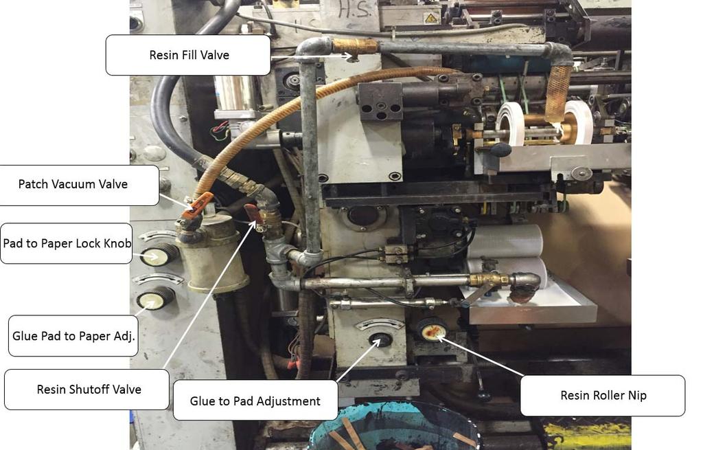
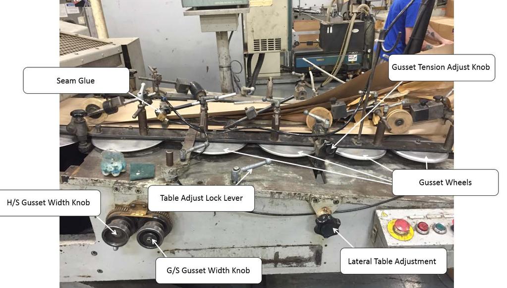
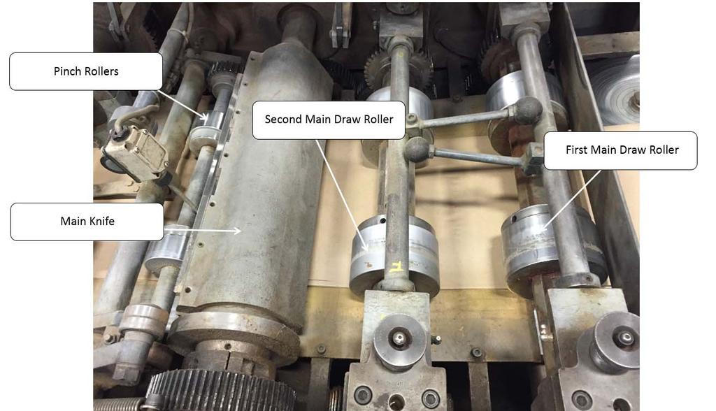
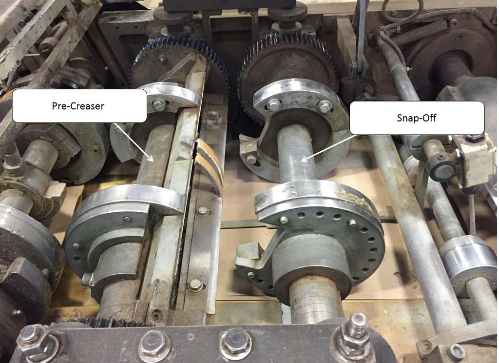
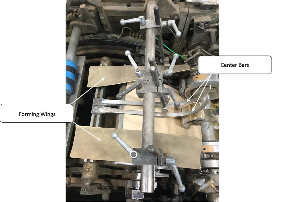
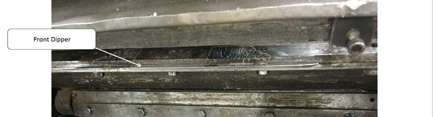
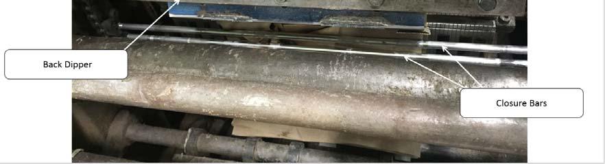
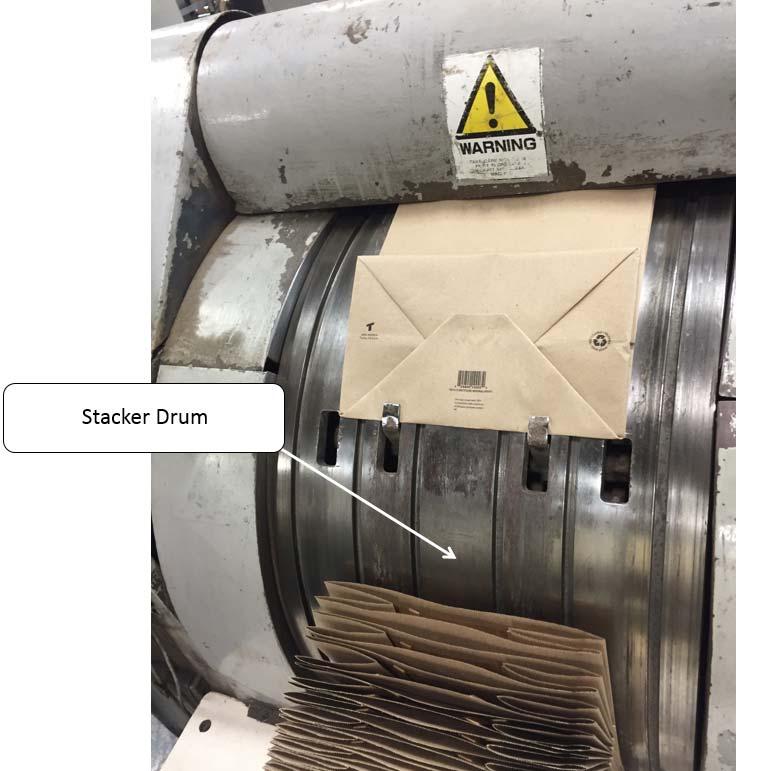
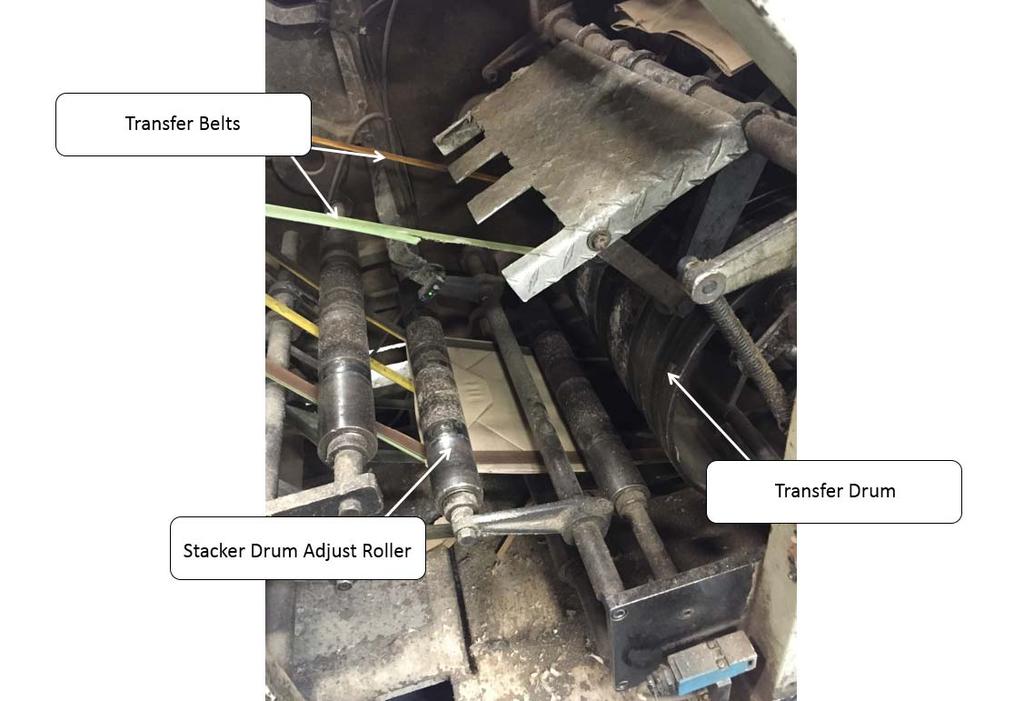
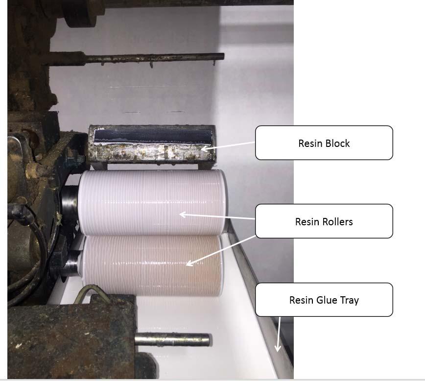
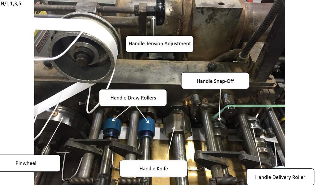
41 Machine Terminology 40
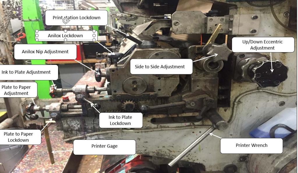
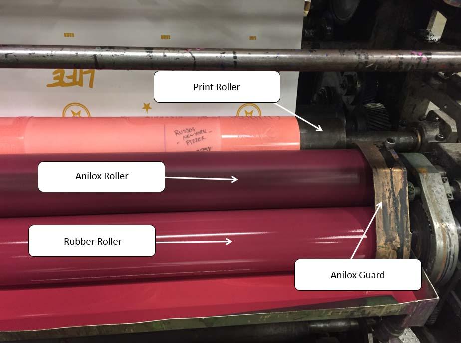
42 41
43 42
44 43


45 General Name: Main Drum 44
46 45
47 46

48 47

49 48
50 Appendix A Safety Signoff Documents 49
51 Safety Training Topic: Taking care of plate marks Operator Training Manual Version 1.0 Plate marks are a common occurrence when using flexographic printing process. In order to keep employees safe, the following procedures have been discussed with the following operator: Procedures: If the plate mark cannot be remedied with adjusting the print dial in: -Stop the machine -Turn off the dry prevent motor of the respective ink station -Remove any guards necessary to access the printing plate -Use necessary means to stick the plate down to prevent the plate marks -When done making adjustments to the printing plate, replace any guards removed, and turn the dry prevent back on before starting the machine NEVER ATTEMPT TO KNOCK DOWN PLATE MARKS WITH YOUR HANDS WHILE THE MACHINE IS RUNNING Operator s Printed Name: Operator s Signature: Date: Supervisor s Printed Name: Supervisor s Signature: Date: 50
52 Safety Training Topic: Proper use of Printer Plate Cylinder Guards All paper bag machines at TULSACK outfitted with guards to cover the plate cylinder must be used properly, and in place, on the machines at the appropriate times. The following are the guidelines: If the machine is in the Run mode, the guards must be in place on the machine covering the Plate Cylinder, with no exception. If the machine is in an Inch, or Jog mode, the guard may be removed for the time during which setup is being done. If the machine is in the off mode, the guard may be removed in order to access the plate to make adjustments. During times allowed to have this guard removed, caution must be used to ensure other powered rollers, such as the rubber and anilox rollers, are not in a moving state while making adjustments. NEVER REMOVE THE PLATE CYLINDER GUARD WHILE THE MACHINE IS IN A RUN MODE TO MAKE ADJUSTMENTS TO, OR ATTEMPT TO CLEAN THE PRINTING PLATE. Operator s Printed Name: Operator s Signature: Date: Supervisor s Printed Name: Supervisor s Signature: Date: 51
53 Safety Training Topic: Cleaning Printing Plates while on the machine Dirty printing plates are a common occurrence when using flexographic printing process. In order to keep employees safe, the following procedures have been discussed with the following operator: Procedures: If the plate is dirty enough that it is necessary to clean: -Stop the machine. -Remove the print cylinder guard if applicable. -Turn OFF the dry prevent motor of the respective ink station -Use a nylon brush and rags to clean the printing plate. -When done cleaning the printing plate, turn the dry prevent back on before starting the machine -Replace the print cylinder guard. NEVER ATTEMPT TO CLEAN THE PRINTING PLATE WITH HOLDING A BRUSH WITH YOUR HANDS WHILE THE MACHINE IS RUNNING Operator s Printed Name: Operator s Signature: Date: Supervisor s Printed Name: Supervisor s Signature: Date: 52
54 Safety Training Topic: Proper use of Resin Roller Guards Several paper bag machines at TULSACK have been outfitted with guards to cover the resin rollers. They must be used properly and on the machines at the appropriate times. The following are the guidelines: If the machine is in the Run mode, the guards must be in place on the machine covering the Resin Roller Area, with no exception. If the machine is in an Inch, or Jog mode, the guards may be removed for the time during which the resin rollers or applicator blocks are being worked on. If the machine is in the off mode, the guard may be removed in order to access the resin rollers or applicator blocks to make adjustments and for cleaning purposes. During times allowed to have this guard removed, caution must be used to ensure other components, such as the resin applicator blocks, are not in a moving state while making adjustments and cleaning. NEVER REMOVE THE RESIN ROLLER GUARD WHILE THE MACHINE IS IN A RUN MODE TO MAKE ADJUSTMENTS TO, OR ATTEMPT TO CLEAN THE RESIN ROLLERS/APPLICATOR BLOCKS Operator s Printed Name: Operator s Signature: Date: Supervisor s Printed Name: Supervisor s Signature: Date: 53
Technical Data. Name: ERIKA Automat fully automatic machine to divide and to round dough pieces of the same size
 AUTOMAT MANUAL 1 Technical Data Name: ERIKA Automat fully automatic machine to divide and to round dough pieces of the same size Type Divisions Dough Portions (in ounces) Plate Nos. 3 30 1.0 3.5 #35 4/40A
Machine Guarding BLR B L B R usi ne B s u s si & n e L s e s g a & l L R e e g s a o l u r R c e e s s o(u 1rc 7 e 1 s 0) 1
 1") Machine Guarding BLR Business BLR Business & Legal & Resources Legal Resources (1710) 1 Session Objectives Recognize machine hazards Identify hazardous machine parts Identify and use machine guards Follow
Machine Guarding BLR Business BLR Business & Legal & Resources Legal Resources (1710) 1 Session Objectives Recognize machine hazards Identify hazardous machine parts Identify and use machine guards Follow
Important Information
 BQ-270 PERFECT BINDER Important Information This manual is designed to help you to install, operate and maintain the BQ-270 Perfect Binder. Please read and understand this manual, and keep it in a safe
Altra Series Dampener
 Crestline TM Altra Series Dampener Installation Instructions Heidelberg MO X88-66 10/97 Rev-A GENERAL INFORMATION ATTENTION CRESTLINE ALTRA SERIES TM DAMPENER OWNER! Accel Graphic Systems provides parts
XC-18. NOTE: *Machine shown without Lift-Up Safety Guard. This guard is included with machine. Machine should not be operated without this guard.
 XC-18 NOTE: *Machine shown without Lift-Up Safety Guard. This guard is included with machine. Machine should not be operated without this guard. EXTREMA MACHINERY COMPANY, INC. PO BOX 1450, ALBANY, LOUISIANA
Bliss Box Former Troubleshooting. 6.1 Troubleshooting Chart. Troubleshooting INTRODUCTION SAFETY PROCEDURES
 6.0 Bliss Box Former 1.0 INTRODUCTION Table 6-1 provides a logical sequence of tests that are designed to isolate problems with the Bliss Box Former machines. This table includes a list of probable causes
Machine Guarding. 1 Copyright 2014, Rev by PEC Safety Management, Inc. PPT-SM-MG 2014, Rev
 Machine Guarding 1 Copyright by PEC Safety Management, Inc. The Importance of Machine Guarding Amputations are among the most severe and disabling workplace injuries Amputations may result from improperly
TA-12. Tabbing System USER'S GUIDE
 TA-12 Tabbing System USER'S GUIDE SAFETY PRECAUTIONS THIS EQUIPMENT PRESENTS NO PROBLEM WHEN USED PROPERLY. HOWEVER, CERTAIN SAFETY RULES SHOULD BE OBSERVED WHEN OPERATING THE TA12 TABBER. BEFORE USING
MACHINE GUARDING. Hazards of Unguarded Machines. Occupational Safety and Health Regulations (OSHA)
") MACHINE GUARDING Hazards of Unguarded Machines Workers are exposed to unguarded or inadequately guarded machines in many workplaces. According to OSHA, workers who operate and maintain machinery suffer
MACHINE GUARDING Hazards of Unguarded Machines Workers are exposed to unguarded or inadequately guarded machines in many workplaces. According to OSHA, workers who operate and maintain machinery suffer
HEDMAN DI-50. Endorser Instructions. Hedman DI-50 Operators Guide
 HEDMAN DI-50 Endorser Instructions Hedman DI-50 Operators Guide 25-0132-20 TABLE OF CONTENTS 1. INTRODUCTION...1 1.1 DI-50 Description...1 1.2 Items Included...1 1.3 Safety Terms...2 1.4 Safety Precautions...3
HOSHIZAKI ICE DISPENSING BIN/ WATER DISPENSER MODEL DM-90A SERVICE MANUAL
 NO.: ISSUED: REVISED: 73091 DEC. 21, 1999 DEC. 17, 2003 HOSHIZAKI ICE DISPENSING BIN/ WATER DISPENSER MODEL DM-90A SERVICE MANUAL IMPORTANT Only qualified service technicians should attempt to service
Sanitise Syrup Lines & Valves. Taylor PH61 Cleaning every 14 days
 Taylor PH61 Cleaning every 14 days Drain the Syrup Lines Remove each syrup feed tube from syrup bottle and let excess syrup drain from the feed tube back into the syrup bottle. When flow of syrup from
Service Manual. Ice Dispensing Bin Models DB-200H. hoshizakiamerica.com
 Service Manual Ice Dispensing Bin Models DB-200H hoshizakiamerica.com Number: 73136 Issued: 5-8-2006 Revised: 2-19-2018 IMPORTANT Only qualified service technicians should attempt to service or maintain
BQ-260/260L. Important Information BOOK BINDER
 BOOK BINDER BQ-260/260L Important Information - This manual is designed to help you to install, operate and maintain Perfect Binder BQ- 260/260L. Read, understand and keep this manual in a safe and convenient
TA-12/HT12 Tabber. OPERATING GUIDE Revised:
 TA-12/HT12 Tabber OPERATING GUIDE Revised: 2-27-13 Neopost USA would like to Thank You for investing in our quality built products. Please record the following information for future reference: Model:
DOCUMENT CREASING MACHINE
 DOCUMENT CREASING MACHINE OPERATORS MANUAL Morgana Systems Limited Snowdon Drive Winterhill Milton Keynes Buckinghamshire MK6 1AP United Kingdom Telephone: ( 01908 ) 608888 Facsimile: ( 01908 ) 692399
Service Manual. Ice Dispensing Bin Models DB-130H. hoshizakiamerica.com
 Service Manual Ice Dispensing Bin Models DB-130H hoshizakiamerica.com Number: 73128 Issued: 5-6-2014 Revised: 2-19-2018 IMPORTANT Only qualified service technicians should attempt to service or maintain
STEP BY STEP MAKEREADY PROCEDURES FOR A DUPLICATOR
 STEP BY STEP MAKEREADY PROCEDURES FOR A DUPLICATOR 1. OBTAIN JOB TICKET AND/OR INSTRUCTIONS a. Make sure that you find out the following things from the job ticket: size of paper, color of ink, quantity
FD Heavy Duty Feeder for FD 280 Tabbing System
 FD 280-10 Heavy Duty Feeder for FD 280 Tabbing System Operator Manual 8/2011 First Edition TABLE OF CONTENTS 1. INTRODUCTION... 1 1.1 Feeder Description... 1 1.2 Items Included... 1 1.3 Operating Manual
BQ-260/260L. Important Information BOOK BINDER
 BOOK BINDER BQ-260/260L Important Information - This manual is designed to help you to install, operate and maintain Perfect Binder BQ- 260/260L. Read, understand and keep this manual in a safe and convenient
BAG ON A ROLL SYSTEM USING THIS MANUAL UNPACK AND INSPECT uline.com READ MANUAL FIRST SAFETY INFORMATION
 BAG ON A ROLL SYSTEM 18002955510 ulinecom USING THIS MANUAL READ MANUAL FIRST IMPORTANT: Please read this manual and familiarize yourself with the equipment before use The manual contains valuable information
OPERATING MANUAL Gfp 255C Please read this manual carefully before operating!
 OPERATING MANUAL Gfp 255C Please read this manual carefully before operating! Unpacking, assembly, and operating videos are available at www.gfpsmoothstart.com 1 Table of Contents Gfp 255C March 2015 Contents
Read All Instructions Thoroughly Before Installing or Using the Disposer.
 SINK PRO NANOGRIND 3 BOLT PRO MOUNT OPERATING & INSTALLATION INSTRUCTION MANUAL BEFORE YOU BEGIN: NOTE: Your XO Food Waste Disposer has been designed exclusively for residential use, for operation on 120V
ASTRO ENVELOPE FEEDER AMC FOR HEIDELBERG PRINTMASTER INSTALLATION AND OPERATING INSTRUCTIONS
 ASTRO ENVELOPE FEEDER AMC-2000-17 FOR HEIDELBERG PRINTMASTER INSTALLATION AND OPERATING INSTRUCTIONS INTRODUCTION Thank you for purchasing the Astro Envelope Feeder. It is fast, efficient, reliable, and
OPERATION AND MAINTNENCE MANUAL
 OPERATION AND MAINTNENCE MANUAL VPI QUALITY WINDOWS 3420 E Ferry Ave. Spokane WA. 99202 TABLE OF CONTENTS Part 1) Storage and Handling... 2 Part 2) Installation, Protection and Initial Cleaning... 2 Part
OPERATING INSTRUCTIONS MIGHTYLAM 2700 ROLL LAMINATOR
 OPERATING INSTRUCTIONS MIGHTYLAM 2700 ROLL LAMINATOR TABLE OF CONTENTS Safety Messages and Electrical Safeguards...3-4 Introduction... Laminator Features...5 Specifications...5 Intial Set-up...6 Operating
CBT LW MAINTENANCE GUIDE
 CBT LW MAINTENANCE GUIDE PICTOGRAMS Each Signifier displayed here is specific to this User Manual. Menu Previous Advance Note Tip Example Powder Feeder Mixing Bowl Weigh Scale CBP Tanks Control Panel PSD
Crestline Dampening System
 Crestline Dampening System Installation Instructions Hamada 500, 600, 700, E-47, SU47 Series Parent Press X88-25 01/2001 Rev-C 2593 GENERAL INFORMATION ATTENTION CRESTLINE DAMPENER OWNER! Accel Graphic
OTO BONDER OWNER S MANUAL WITH CIRCULATING SYSTEM MACHINERY DIVISION - - L to R Unit Shown
 GBAC RROTO OTO BONDER BONDER WITH CIRCULATING SYSTEM G B MACHINERY DIVISION OWNER S MANUAL L to R Unit Shown - - IMPORTANT FOREWORD 1) To ensure efficiency, the GBAC must be properly maintained. Carefully
ICED CAPPUCCINO MACHINE Taylor MODEL: 390
 4.8.6.3 ICED CAPPUCCINO MACHINE Taylor MODEL: 390 LOCATION: Front of House WHEN CLEANED: Daily, Weekly, Monthly, Seasonal TOOLS/SUPPLIES REQUIRED: Salmon Cloth 2 or 3-Compartment Sink Sink Detergent Sanitizer
ENGINEER S MANUAL No.01
 1-NEEDLE, UNISON FEED, LOCKSTITCH MACHINE (AUTOMATIC LUBRICATION) LU-1510 1-NEEDLE, UNISON FEED, LOCKSTITCH MACHINE WITH AUTOMATIC THREAD TRIMMER (AUTOMATIC LUBRICATION) LU-1510-7 1-NEEDLE, UNISON FEED,
XPS-ProDry User s Guide Dryer Base
 XPS-ProDry User s Guide XPS-ProDry User s Guide Dryer Base For Use with Inkjet Imaging Systems Manual Part#: M-3120 Revision: August 2005 XPS-ProDry User s Guide Written by Frank Mauri & John Brand Published
ATTIAS MANUFACTURERS OF ATTIAS DOUGH MIXERS 265 BOWERY NEW YORK, N.Y TEL: (212) FAX: (212) COMMERCIAL DOUGH MIXERS
 FAX: (212) COMMERCIAL DOUGH MIXERS") ATTIAS MANUFACTURERS OF ATTIAS DOUGH MIXERS 265 BOWERY NEW YORK, N.Y. 10002 TEL: (212) 475-0145 FAX: (212) 979-1423 COMMERCIAL DOUGH MIXERS INSTALLATION AND OPERATING INSTRUCTION MANUAL MODEL# USA-60 MODEL#
ATTIAS MANUFACTURERS OF ATTIAS DOUGH MIXERS 265 BOWERY NEW YORK, N.Y. 10002 TEL: (212) 475-0145 FAX: (212) 979-1423 COMMERCIAL DOUGH MIXERS INSTALLATION AND OPERATING INSTRUCTION MANUAL MODEL# USA-60 MODEL#
INSTALLATION AND MAINTENANCE OF THE "THOMPSON-BRITISH" AUTOMATIC PLATEN
 INSTALLATION AND MAINTENANCE OF THE "THOMPSON-BRITISH" AUTOMATIC PLATEN Installation and Maintenance of The "Thompson-British" Auto Platen Lifting Bolt. Motor. Direction of rotation. Oiling. The machine
KF-250 Knife Folding Machine
 KF-250 Knife Folding Machine Serial Number Date Page left blank intentionally 2 Table of Contents INTRODUCTION... 5 PREFACE... 5 SPECIFICATIONS... 5 ELECTRICAL SPECIFICATIONS... 6 SAFETY PROCEDURES...
IMPORTANT SAFETY INSTRUCTIONS
 CONTENTS 1.SPECIFICATIONS... 1 2.INSTALLATION... 1 3.INSTALLATION OF THE SYNCHRONIZER... 2 4.ASSEMBLY OF HAND WHEEL... 2 5.INSTALLATION OF HAND WHEEL... 2 6.INSTALLING THE BELT COVER... 3 7.ADJUSTING THE
Operator's Manual. Fold System multipli 35.
 Mathias Bäuerle GmbH Gewerbehallestraße 7- D-78 St.Georgen Telefon (077) 88-0 Telefax (077) 88- Internet: http://www.mbfold.de E-mail: center@mbfold.de Fold System multipli 5 Operator's Manual Operator's
HOSHIZAKI ICE DISPENSING BIN/ WATER DISPENSER MODEL DM-90A INSTRUCTION MANUAL
 ISSUED: AUG. 2, 1999 REVISED: FEB. 28, 2000 HOSHIZAKI ICE DISPENSING BIN/ WATER DISPENSER MODEL DM-90A INSTRUCTION MANUAL FOREWORD IMPORTANT Only qualified service technicians should attempt to install,
HEDMAN The HEDMAN Company 189 Gordon St. Elk Grove Village, IL
 HEDMAN The HEDMAN Company 189 Gordon St. Elk Grove Village, IL 60007 800-872-2788 NOTICE Proprietary Information - this material is not to be reproduced by any means or disclosed in any way without prior
 www.whitakerbrothers.com The Challenge Machinery Company provides owner's manuals on its products solely as a courtesy to its customers. See the information below before using this manual. These manuals
PS-2/ES Automated pack & tag machine with IndES fastening system
 English Manual PS-2/ES Automated pack & tag machine with IndES fastening system Contents 1. Introduction 2. Important Safety Instructions 3. PS-2/ES 4. Unpacking the machine 5. Setting up the machine 6
Section - A Vacuum Feed Attachment
 Tray Box Former 1.0 Section - A Vacuum Feed Attachment A-1 Table of Contents SECTION NO. PAGE SECTION NO. PAGE A.0 INTRODUCTION PURPOSE... A-3 A.1 SET-UP AND ADJUSTMENTS FIGURE A-1 VACUUM FEED MOUNTING
Parts and Service Manual BURNISHER MODEL: MR , MR , MR , MR
 Parts and Service Manual BURNISHER MODEL: MR2000-115, MR1500-115, MR2000-220, MR1500-220 TABLE OF CONTENTS RECEIVING YOUR EQUIPMENT... 3 WARNINGS AND SAFETY... 3 ELECTRICAL INFORMATION... 4 GROUNDING INSTRUCTIONS...
K 2.97 M. Specifications Operating pressure, max PSI Water volume GPM Voltage V Amp draw AMPS
 K 2.97 M High Pressure Washer Operator Manual Overview... 2 Important Precautions... 3-4 Assembly Instructions... 4 Operating Instructions... 5 GFCI Instructions... 6 Using the Accessories... 6 Working
The purpose of this document is to provide guidance on the need and solutions to proper machine guarding in the workplace.
 Machine Guarding University of Tennessee Safety Guide GS-060 Document Contact: EHS-General Safety Date effective: January 1, 2009 Revision Date: April 1, 2014 Purpose According to OSHA there are approximately
Conveyor Washer Operation Manual
 Douglas Machines Corp. Conveyor Washer Operation Manual Douglas Machines Corp. 2101 Calumet Street Clearwater, FL 33765 Ph. (727) 461-3477 Fax (727) 449-0029 Do s and Don ts DO Wear Safety Glasses Wear
Industrial Sewing Machine TECHNICAL MANUAL SEWING MACHINE HEAD. Electronic Pattern Sewing Machine. Model PLK-G1010 A180E593P03
 Industrial Sewing Machine TECHNICAL MANUAL SEWING MACHINE HEAD Electronic Pattern Sewing Machine Model PLK-G1010 A180E593P03 FOR SAFE USE Before the installation, operation, and inspection for this product,
INSTRUCTION MANUAL HL600, HL600C, & HL662 ML ML ML ML ML S. RIDGE AVENUE TROY, OHIO
 INSTRUCTION MANUAL Models HL600, HL600C, & HL662 ML-141063 ML-141070 ML-141069 ML-141066 ML-141068 701 S. RIDGE AVENUE TROY, OHIO 45374-0001 937 332-3000 www.hobartcorp.com F45213 (March 2012) Table of
Fig. 1. Bottle Height---Top of bottle MUST be at this height or slightly higher.
 P12 Corker Addendum: Setup and Maintenance Read this addendum and the MEP manual carefully before operating the corker. One person should be assigned to maintain the corker. Only this primary operator
INSTRUCTION MANUAL FOR DUTCHESS MODEL 260 BAGEL & BUN SLICER
 INSTRUCTION MANUAL FOR DUTCHESS MODEL 260 BAGEL & BUN SLICER Table of Contents Safety Information I thru VII Uncrating Instructions 1 Introduction 2 Adjustment Instructions 3 Operating Instructions, Cleaning,
LBX-2000 POWER STRAPPING MACHINE
 LBX-2000 POWER STRAPPING MACHINE Copyright 2008, Signode 439998 9/2008 (EN) CONGRATULATIONS Thank you for purchasing your LBX-2000 Walk-Up Strapping Machine. The LBX- 2000 Strapping Machine was designed
OPERATING & SERVICE PARTS MANUAL HDS-215 COMBINATION SHRINK SYSTEM
 OPERATING & SERVICE PARTS MANUAL HDS-215 COMBINATION SHRINK SYSTEM FOR HOT KNIFE AND IMPULSE MACHINES READ ALL INSTRUCTIONS CAREFULLY BEFORE OPERATING EQUIPMENT TABLE OF CONTENTS Electrical Requirements
MANUAL VERSION SERIAL # X-1 MINI PRO OWNER S MANUAL ASSEMBLY & OPERATOR INSTRUCTIONS 1.0
 SERIAL # MANUAL VERSION 1.0 Introduction WARNING: To limit risk of potential injury and material damage, all users must read these instructions in their entirety and follow them strictly. Check our YouTube
I N ST R UC T I ON MODEL 2612 & 2712 SLICERS MODELS 2612 ML ML FORM (12-98) 2612 SLICER
 2612 SLICER") I N ST R UC 2612 SLICER T I ON S MODEL 2612 & 2712 SLICERS MODELS 2612 ML-104829 2712 ML-104822 701 S. RIDGE AVENUE TROY, OHIO 45374-0001 FORM 34141 (12-98) Installation, Operation, and Care of MODEL 2612
I N ST R UC 2612 SLICER T I ON S MODEL 2612 & 2712 SLICERS MODELS 2612 ML-104829 2712 ML-104822 701 S. RIDGE AVENUE TROY, OHIO 45374-0001 FORM 34141 (12-98) Installation, Operation, and Care of MODEL 2612
Rotary Gutter Cleaning System. Operator s Manual
 Rotary Gutter Cleaning System Operator s Manual Thank you for purchasing the VertaLok Rotary Gutter Cleaning System. Please follow the important safeguards and operating instructions included within this
MACHINE GUARDING: PROTECTING YOU FROM HAZARDS
 MACHINE GUARDING: PROTECTING YOU FROM HAZARDS This easy-to-use Leaders Guide is provided to assist in conducting a successful presentation. Featured are: INTRODUCTION: A brief description of the program
Mill, Microcut Grinder STANDARD OPERATING PROCEDURE
 STANDARD OPERATING PROCEDURE Mill, Microcut Grinder Model: MC-15 Manufacturer: Stephan Machinery, Inc. Location: Wet Processing Pilot Plant, 1091 Food Sciences Building Publication Date: 07/23/2014 Iowa
PLC-1700 Series PLC-1710, , 1760, , 1760L
 Post-bed, Unison-feed, Lockstitch Machine PLC-1700 Series PLC-1710, 1710-7, 1760, 1760-7, 1760L ENGINEER S MANUAL 40040656 No.E372-00 Introduction This Engineer s Manual is for technical service engineers.
Audi-Larm Audible Alarm
 Audi-Larm Audible Alarm MAINTENANCE AND REPAIR TAL 1706 (L) Rev. 7 MSA 2017 Prnt. Spec. 10000005389(I) Mat. 10093084 Doc. 10093084 REPLACEMENT KITS AND PARTS LIST TAL 1706 (L) Rev. 7-10093084 2 Exploded
45 Wide Format Hot and Cold Laminator
 45 Wide Format Hot and Cold Laminator 1 IMPORTANT SAFEGUARDS OPERATING INSTRUCTIONS TCC1200 When using electrical machines, basic precautions should always be followed to reduce the risk of electric shock
Instruction Book for HD Punch Machines
 Instruction Book for HD Punch Machines HD7700, HD7000 & HD7500H Setup & Operator Manual Issue 5 February 2012 Performance Design LLC. These electric punches have been designed to punch most any job that
Instructions for Colonel Electric Label Gluer
 Instructions for Colonel Electric Label Gluer Remove the packing materials and carefully remove the gluer from the wooden crate. It is strongly recommended that you apply some 30 weight oil to the two
R20SC, R20E & R20ENT. Owner s Manual
 R20SC, R20E & R20ENT Owner s Manual Contents Getting Started Important Safety Instructions... 2 Polarization Instructions... 3 State of California Proposition 65 Warnings... 3 Description of the Vacuum...
EAGLE 2000B EAGLE 2000BE EAGLE 2000EBT MUST READ MANUAL PRIOR TO INSTALLING MACHINE
 EAGLE 2000B EAGLE 2000BE EAGLE 2000EBT MUST READ MANUAL PRIOR TO INSTALLING MACHINE Contents 1 Machine Safety Information 3 1.5 Safety Precautions Prior to Operating Machine 6 2 Machine Installation 7
CBT Bowl & wrap replacement
 CBT bowl & wrap replacement 2 CBT BOWL & WRAP REPLACEMENT Revision History rev. level 01_03.14.2012 rev. level 02_03.19.2012 rev. level 03_03.23.2012 rev. level 04_05.30.2013 NOTE: due to the fact that
2EZSB LEFT HANDED PWR MAG SET UP GUIDELINES 2EZSB Case Erector Setup Guidelines. Left Handed Machine
 2EZSB Case Erector Setup Guidelines Left Handed Machine E 1 F A H C G B D Figure 1 Overview 1 Controls (may vary from machine to machine) A - Magazine Height Adjustment Crank with Indicator (case width)
Model PLK-G5050 PLK-G10050
 Industrial Sewing Machine TECHNICAL MANUAL SEWING MACHINE HEAD Electronic Pattern Sewing Machine Model PLK-G5050 PLK-G10050 A180E686P01 FOR SAFE USE Before the installation, operation, and inspection for
Rotovac WIDE-TRACK Page 1 WIDE-TRACK
 Rotovac WIDE-TRACK Page 1 WIDE-TRACK Extraction System Owner s Manual WT/11/28/2007 Rotovac WIDE-TRACK Page 2 OVERVIEW The Rotovac WIDE-TRACK is the largest and most advanced Rotary Jet Extraction machine
Reliability is a beautiful thing TM CUBELET ICE DISPENSER DCM-500BAF DCM-500BWF DCM-750BAF DCM-750BWF INSTRUCTION MANUAL
 Reliability is a beautiful thing TM CUBELET ICE DISPENSER DCM-500BAF DCM-500BWF DCM-750BAF DCM-750BWF INSTRUCTION MANUAL ISSUED: APRIL 13, 1998 REVISED: NOV. 18, 2003 IMPORTANT Only qualified service technicians
Machine MANUAL. Soft Serve - Countertop - Two Flavor + Twist. Spaceman USA, LLC. Sales and Product Information Sunday Saturday 8 AM 5 PM Mountain
 Machine MANUAL MODEL SM-6235H Soft Serve - Countertop - Two Flavor + Twist Customer Service Spaceman USA, LLC Sales and Product Information Sunday Saturday 8 AM 5 PM Mountain 226 Commerce Street Suite
INSTRUCTIONS MANUAL. 8-Speed Stand Mixer
 INSTRUCTIONS MANUAL 8-Speed Stand Mixer MM-106W (White) MM-106R (Red) THIS PRODUCT IS FOR HOUSEHOLD USE ONLY! PLEASE READ THIS MANUAL THOROUGHLY BEFORE FIRST USE AND SAVE IT FOR FUTURE REFERENCE. General
SOP: LFA SOP For Automatic Capsule Filling Machine
 SOP For Automatic Capsule Filling Machine Alastair Sanderson 31/08/16 1 Objective To provide the operating procedure for Automatic Capsule Filling Machine. 2 Scope Includes the operating procedure for
General Characteristics.3. S.M.A.R.T System Set-up...5. Start-up Procedures.6. Shut-down Procedures 8. General Maintenance..8
 1-800-661-3842 1 TABLE OF CONTENTS General Characteristics.3 How the S.M.A.R.T System Works..3 S.M.A.R.T Technical Specifications..3 Erecting the S.M.A.R.T System..4 S.M.A.R.T System Set-up...5 Start-up
NSS STANDARD-SPEED FLOOR MACHINES
 OPERATION MANUAL NSS STANDARD-SPEED FLOOR MACHINES IMPORTANT SAFETY INSTRUCTIONS Read all instructions before using or servicing machine. WARNING: Fire or explosion hazard. NEVER use with flammable or
 Automatic Temperature Control (ATC) is a system that operates the broiler at two different energy rates. 1. High energy input - for initial warm-up and periods of high volume. 2. Low energy input - for
541D19 SERIES. Technical Manual. A Division of Aquion Partners L.P.
 541D19 SERIES Technical Manual A Division of Aquion Partners L.P. Table of Contents Introduction... Page 1 Technical Specifications... Page 2 Flow Diagrams... Page 3 Injector & Flow Control Selection Injector...
Page 1 of 18. Part# /5/2013
 Part# 1002655-06 8/5/2013 This manual contains important information concerning the installation and operation of the gun washers listed above. Read manual thoroughly and keep for future reference INSTRUCTIONS
INSTALLATION & OPERATING INSTRUCTIONS
 INSTALLATION & OPERATING INSTRUCTIONS WARNING RISK OF ELECTRIC SHOCK. CONNECT ONLY TO A CIRCUIT PROTECTED BY A GROUND-FAULT CIRCUIT-INTERRUPTER. THE UNIT SHOULD BE INSTALLED BY A QUALIFIED SERVICE REPRESENTATIVE.
Nilfisk Inc Winnetka Avenue North Minneapolis, MN REV.03( ) VF80189
 VF80189") Nilfisk Inc. 9435 Winnetka Avenue North Minneapolis, MN 55445 www.usviper.com REV.03(05-) VF8089 SAFETY PRECAUTIONS This machine is intended for commercial use. It is constructed for use in an indoor
Nilfisk Inc. 9435 Winnetka Avenue North Minneapolis, MN 55445 www.usviper.com REV.03(05-) VF8089 SAFETY PRECAUTIONS This machine is intended for commercial use. It is constructed for use in an indoor
CUTMASTER Strip Cutting Machine
 EASTMAN THE EASTMAN CUTMASTER Strip Cutting Machine WARNING Safety glasses must be worn at all times when operating or servicing this equipment. Instruction Manual & Illustrated Parts List Please read
How to Use Your National Cash Register Class 500
 How to Use Your National Cash Register Class 500 Follow Directions It is important to follow direction for the use of this register. Often a register is thought to need some repairs or adjustment when
BMW E36 Thermostat Removal And Coolant Flush
 BMW E36 Thermostat Removal And Coolant Flush Disclaimer: The cooling system is critical to the proper operation of your car. Failure to properly install all of the components of the cooling system could
last editted by: Yuyang Chen last edited: 3/12/20152:52:00 PM Page 1 of 1
 Name Refill friction stir spot welder Description RPS 100 spot friction welding system Valid from software version V02.21 Manufacturer and Harms & Wende GmbH & Co KG Model Location E3 2118J SOP Creation
HD150. Introduction. Table of Contents
 Introduction To the owner or user: This product manual is a source of information about the installation, start up, cleaning, maintenance and repair of the product. The is a hotel/motel ice dispenser.
Industrial Sewing Machine TECHICAL MANUAL SEWING MACHINE HEAD. Electronic Pattern Sewing Machine. Model PLK-G1010 A180E593P02
 Industrial Sewing Machine TECHICAL MANUAL SEWING MACHINE HEAD Electronic Pattern Sewing Machine Model PLK-G1010 A180E593P02 FOR SAFE USE Before the installation, operation, and inspection for this product,
Bottle Height Adjustment Bottle Diameter Adjustment Cork Length Adjustment Cork Depth Adjustment
 P55 Champagne Corker Setup and Maintenance Read this carefully before operating the corker. One person should be assigned to maintain the corker. Only this primary operator should make adjustments to the
1217A Operating Instructions
 1217A Operating Instructions Reversible Motor Friction Fed Conveyor Stacker Easy Disassembly Adjustable Folds Counter Available MADE IN USA SPECIFICATIONS Paper Weight.28 Lbs. Bond, 90Lbs. Cover, 135Lbs.
RTP9 ROTARY TABLET PRESS USER MANUAL
 RTP9 ROTARY TABLET PRESS USER MANUAL LFA Tablet Presses is a trading name of LFA Machines Oxford LTD All of the content in this document is covered by copyright CONTENTS Page 1. Introduction Page 1. Technical
PORTABLE HAND POWER THREADER 1/2-2
 PORTABLE HAND POWER THREADER 1/2-2 Read this Operator s Manual carefully before using this tool. Failure to understand and follow the contents of this manual may result in electrical shock, fire and/or
MAINTENANCE MANUAL TAIYO SEIKI CO., LTD.
 MAINTENANCE MANUAL TAIYO SEIKI CO., LTD. Introduction This Maintenance Manual explains how to replace and adjust the major components of the Automatic Taping Machine when required in daily operation.
FM-17HD & FM-20HD FLOOR MACHINES
 PARTS & OPERATING MANUAL FM-17HD & FM-20HD FLOOR MACHINES PLEASE READ THIS BOOK This operator s book has important information for the use and safe operation of this machine. Read this book carefully before
Product instruction manual Easymount Wide Format Laminators
 Product instruction manual Easymount Wide Format Laminators The Easymount has been designed to be user friendly, however we strongly recommend you take a few minutes to read through this manual to ensure
V-VTP Maintenance Manual
 V-VTP Maintenance Manual PO Box 501 Denver, NC 28037 ph: 704-483-9316 / fx: 704-483-4538 sales@leonardautomatics.com - http://leonardautomatics.com Maintenance Guide Proper maintenance of the tunnel finisher
Cable Drum Machine. Operation Manual 40 SERIES. Cleans 2" to 4" lines up to 75' N O T F O R R O O T S
 Cable Drum Machine Operation Manual 40 SERIES Cleans 2" to 4" lines up to 75' Used For: Sinks, Showers & Floor Drains N O T F O R R O O T S WARNING - Read All Instructions, When Using Electric Tools, Basic
A) Take your VMI Cleaner Disc and place the label side down onto loading tray.
 Take your VMI Cleaner Disc and place the label side down onto loading tray.") Maintaining Your Buffing Wheels The VMI 3550i will indicate when it is time to run a cleaning cycle for the buffing wheels. After 15 cycles the USE CLEANER DISC lights will flash indicating that after
Maintaining Your Buffing Wheels The VMI 3550i will indicate when it is time to run a cleaning cycle for the buffing wheels. After 15 cycles the USE CLEANER DISC lights will flash indicating that after
Grafisk Maskinfabrik A/S Bregnerødvej 92, DK-3460 Birkerød, Denmark. Website: Phone:
 IR330 Inspection Rewinder with Label Dispenser & Inkjet IR330 Operation Manual Grafisk Maskinfabrik A/S Bregnerødvej 92, DK-3460 Birkerød, Denmark. Website: www.gm.dk. E-Mail: gm@gm.dk. Phone: +45 4581
OPERATING MANUAL Gfp 800 Series
 OPERATING MANUAL Gfp 800 Series Please read this manual carefully before operating! 1 Contents Table of Contents Page 1. Introduction 3 2. Important Safety Instructions.. 3 3. Installation Safeguards..
16 OUTDOOR MISTING FAN
 16 OUTDOOR MISTING FAN Model: SF-1670M READ AND SAVE THESE SAFETY INSTRUCTIONS BEFORE USE IMPORTANT SAFETY INSTRUCTIONS When using electrical appliances, basic precautions should always be followed to
Operating Instructions
 1 HB 0701 AX0 UK HB 0703 AX0 UK HB 0705 AX0 UK 2 3 4 13 8 12 16 11 14 9 15 9 8 19 18 17 17 11 10 14 7 5 15 7 18 12 6 6 19 Indesit Company UK Ltd Morley Way, Peterborough PE2 9JB www.indesitcompany.com
Register at
 Power Shovel Model No. 38361 Serial No. 313000001 and Up Register at www.toro.com. If, after carefully reading this manual, you still have questions or problems, call toll free 1-800-808-2963 (US) or 1-800-808-3072