HEAT PUMP INSTALLATION GUIDELINES
|
|
|
- Dinah Cobb
- 5 years ago
- Views:
Transcription
1 HEAT PUMP INSTALLATION GUIDELINES 1. HEAT PUMP DESIGN AND REGULATIONS Heat Pump technology has been used successfully for more than 50 years and the most important step in designing and installing a heat pump system is the correct sizing of the heat pump. This has to be done accurately to allow the heat pump to properly deliver the Heating (by covering the heat loss of the building) & DHW requirements (depending on relevant hot water taping profile) for the proposed dwelling/building. This is to be done in accordance with the current regulations and guidance documents published by the relevant bodies. i.e. CIBSE, NSAI standards, Building Regulations, etc. to allow the designer or installer of a heat pump to select the most beneficial solution for the end user, from both a capital cost investment and running & maintenance costs point of view. For new buildings the capital cost is not a decisive factor in using or not the heat pump, as more and more heat pumps are being used as the preferred heat source and also this initial cost can be easy enough absorbed in the overall cost of building a new dwelling. As a retrofit solution though the cost of installing a heat pump can be prohibitive, as it has to be done in conjunction with some other major upgrades fabric & ventilation of the building, to ensure that the new heat source will work efficiently and will suit this type of application. Heat Pump efficiency is the ratio of the heating or cooling delivered to the electrical energy required to operate the system using a refrigerant. The ratios are given in two ways: Coefficient of Performance (COP) the ratio of heating delivered to the electrical energy input Energy Efficiency Ratio (EER) the ratio of cooling delivered to the electrical energy input The higher the COP or EER, the greater is the efficiency of the heating or cooling system. COP can be calculated by taking the heating output (in kw) and dividing it by the electrical input (in kw). These values can be found in the energy rating label or manufacturer s information. You can also get a Seasonal Coefficient of Performance or Seasonal Performance Factor (SCOP or SPF) the ratio of heating delivered to the electrical energy input on an annual basis. The COP values reflects the efficiency of the heat pump in certain laboratory testing conditions 7 C outdoor & 35 C flow temperatures, where the SCOP/SPF looks at the annual efficiency of the heat pump and takes in account the variation of the outdoor temperature throughout the year usually the COP is greater than the SCOP/SPF, but the lather is more of a true reflection of the efficiency of the heat pump. A Refrigerant is the fluid that facilitates the energy transfer to take place between the outdoor and indoor, due its special physical & chemical properties and it is used by all heat pumps. The EN378 F-Gas European Standard guides people in the areas of d e s i g n, construction, installation, operation and maintenance on
2 the Safety and Environmental use of vapour compression systems for refrigeration, heat pumps, chillers and air conditioning systems. There are two main types of refrigerants: Natural type: i.e. ammonia, propane and CO₂ and synthetic type: i.e. R134a, R407C, R410a and most recent R32. The F- gas regulation is driving industry to use lower GWP refrigerants in many applications and EU regulation (517/2014), which came into force on the 1st January 2015, introduces a ban on new equipment using HFC refrigerants with a GWP of over 2500 by The regulation also introduces a phase down, related to GWP and measured in CO2 equivalent tonnes, which will drive industry to use lower GWP options. As a result, a new family of refrigerants both pure fluids and blends has been (and continues to be) developed - these are Hydro Fluoro Olefins (HFO). A feature of many of these products (and some existing refrigerants such as R32 and Ammonia) is that they exhibit lower flammability, and hence a new classification has been introduced by ASHRAE to cover this feature A2L. (In the case of Ammonia the classification is B2L, due to its toxicity). There are a few important things to be considered when designing the system and sizing the heat pump, in accordance with NSAI recommendations the system should be designed and constructed in accordance with the Building Regulations, Irish Standards, the EU Energy Performance of Buildings Directive (EPBD) and the Building Energy Rating scheme (BER) : Heat loss calculations in accordance with NSAI SR50-1 should be done for the proposed dwelling, either for new, renovation or retrofit project and the heat pump should be sized in accordance with this and in-line with current recommendations from SEAI regarding Heat Pump Tool for DEAP See below example of heat loss calculations based on above standard based 7.6 Fabric Heat loss Fabric heat losses are losses directly through the walls, windows, doors, floors and ceiling of the room. For ease of calculation, it is assumed that these losses are at a uniform rate through each surface. The heat loss rates are obtained by multiplying the area of each individual surface by the design temperature difference and the heat transfer co-efficient called the 'U' Value. For further details reference should be drawn from I.S. EN ISO The 'U Value' of a building fabric is the thermal conductivity of a material (rate of loss of heat in watts) that will flow through one square metre of the material when there is a temperature difference of one degree Kelvin (K). To calculate the heat loss through the whole wall for each degree difference, multiply; the U value by the wall area and then by the temperature difference between the inside and outside of the wall. Design heat loss through wall = Surface area (m²) x 'U' Value (w/m²/ K)x Temperature difference (ΔT) Fabric Heat Loss (Watts) = Area (m²) X U Value (W/m²x C) X ΔT ( C) The U value of a material can be found from the manufacturer or from tables such as that TGD Part L Appendix B. Methods can also be found in I.S. EN ISO 6946 and also in the CIBSE guide. I. on SR50-1 fabric heat loss calculation and ventilation rates:
3 Domestic Heat Loss Calculation worksheet ROOM Kitchen/Dining room Job Title Design Room Temp 21 No. of air changes Subtract Outside Design Temp -3 per hour ac/h Design Temp Diff 24 Length (m) Room Volume (meters) Width (m) Height (m) Amount of air to be heated per hour m 3 /h Air change factor W/m 3.K Page of Design Temp Diff degc Heat Loss Watts Ventilation Heat Loss Fabric Heat Loss Area m 2 U-Value W/m 2.K Floor Ex Wall (Gross area) Glazing Ex Wall (Nett area) Door Subtract glazing and door areas from gross external wall area Ceiling or Roof (Gross area) Heat gain from bathroom Roof Glazing Celing or Roof (Nett area) Subtract roof glazing area from gross roof area Internal Wall Internal Wall Party Wall Other Design Heat Loss from Room (Sum of Watts for all elements) Exposed Location? Yes If Yes, add High Ceiling? No If Yes, add 10 % to Design Heat Loss % to Design Heat Loss - Total room Heat Loss
4 7.7 Ventilation Rate The difference between the inside and outside temperatures and the rate at which the air enters and leaves the building will affect the ventilation heat loss. The ventilation heat loss rate of a room or building is calculated by the following formula; Rate of Heat Loss = V * N * ΔT * 0.33 where; V = the volume of air in the room (m3), N = number of air changes per hour, ΔT = Temperature difference between the outside and the inside, and, 0.33 = is a constant factor. It represents the specific heat and density of air. The principal design considerations are: - the required internal temperatures of each room, - the design outside temperature (Range -1 C to -3 C), and - the ventilation rate of the room(s). The calculations should include provisions to ensure that the heating up time of the entire system is not excessive. The general principle is to calculate the heat loss rate and the correct radiator (heat emitter) sizes, for each room in turn. Then total all heat losses to obtain a total figure. For further details reference should be drawn from I.S. EN ISO II. The hot water requirement to be taken in account is based on the hot water taping profile for the dwelling; to be noted that most of the heat pumps are sized to cover either the heating or DHW load, not the combined one, as the DHW production is done outside the heating demand. The DHW requirement is to be calculated according to EU Ecodesign Standardised User Profiles i.e. S-Small, M-Medium, L-Large and XL-Extra-large or based on occupancy average usage in line with current standards. III. Oversizing the heat pump will significantly increase the installed cost for little operational saving, and will mean that the period of operation under part load is increased. Frequent cycling reduces equipment life and operating efficiency. If the system is undersized, design conditions may not be met and the use of top-up heating, usually direct acting electric heating, will reduce the overall system efficiency IV. A Heat Pump system can be designed to provide all the required heat a monovalent system. However, because of the limitations in maximum heat output of single phase heat pumps it may be prudent to consider a bivalent system where the heat pump is designed to cover the base heating load, while an auxiliary system covers the additional peak demand a bivalent system. V. The majority of heat pumps have an operating temperature limit of 50 C 55 C in most applications. Reducing the output temperature required from the heat pump will increase its performance; ideally the flow temperature should be 35 C for UFH systems and 45 C for Fan coil/low temperature radiator systems. These are not suitable for monovalent operation in combination with existing or traditionally sized, high temperature wet radiator distribution systems, or for providing all the domestic water heating as they will not be able to raise the water temperature to that required (60 C) to
5 VI. VII. VIII. avoid the risk of Legionella. In this instance most heat pumps use a booster heater/electrical immersion to complete the Anti-legionella/Disinfection cycle. A few heat pumps, however, can provide output temperatures of up to 65 C and specially designed two stage compressor heat pumps can provide output temperatures of up to 80 C. NOTE: You should check with the Heat Pump Manufacturer/Supplier if the heat pump is suitable for your dwelling. Pipe sizing and circulation pumps are critical for the correct operation of the heat pump and the heating system. The designer/installer of the heat pump should make sure that a minimum DN25 (1 copper or 32mm PEX or MLC pipe) Flow & Return pipe work is in place from the heat pump to the distribution manifolds or motorized valves, to allow the heat pump to achieve its minimum required flow rates that enables the heat pump to deliver the output that it was designed for. Same for the circulation pump. Under sizing the pipe work will have a knock-on effect: the building will hardly reach the desired comfort temperature and as a result will have frequent cycling of the compressor, reducing its life time. Correct sizing of the heat emitters base on heat loss calculations, see paragraph I above making sure that the heat output delivered by the heat pump can be efficiently transferred to the building and correct sizing & appropriate location of the DHW cylinder making sure that we are getting the benefits of the heat pump, as the DHW production is usually at much lower efficiency than heating efficiency. For renovations/retrofit projects only under certain circumstances existing pipework, heat emitters or DHW cylinder may be reused. For the heating system this is to be assessed based on provided heat loss calculations on a room by room basis. Firstly is to be assessed if the existing heat emitters output can meet the heat load required based on a lower flow temperature provided by the heat pump by using the manufacturer s correction factors. i.e. at Δt=50 C (flow temp. 80 C/return temp. 60 C and room temp. 20 C) a radiator s output is 2,000Watts. Same radiator at Δt=30 C (flow temp. 55 C/return temp. 45 C and room temp. 20 C) and correction factor of will only deliver 850Watts and furthermore at Δt=22.5 C (flow temp. 45 C/return temp. 40 C and room temp. 20 C) and correction factor of 0.3 will only deliver 600Watts. Reusing the pipework is not recommended, as most of the time the existing pipework has been designed for gas or oil boilers systems with higher flow temperatures and flow rates used which are not suitable for low temperature heat pump systems. The same principle will apply for existing DHW cylinders. If a high temperature heat pump is being used, capable of delivering 80 C flow temperature, it is possible to use the existing heating and DHW system, considering though the reduced efficiency/spf of the new system. Also it is to be considered the compliance with the ErP Energy Label and EU ECODESIGN Lot 1&2 directive for combination heaters when considering reusing an existing DHW cylinder. See below guidance on determining the correct Δt for different flow/return and air temperatures: The following note should be considered when replacing the heating system i.e. Radiators, boilers etc. - this guidance note is for information only. The radiator is sized according to the heat required for a given room.
6 The heat is measured in Watts (W) or British Thermal Units (BTUs) [1W = BTU] Heat requirement The heat required for a room depends on two factors: the temperature you want to maintain in the room and the rate of heat loss from that room. The following are recommended temperatures required for rooms depending on their type: Living areas i.e. sitting room, dining room, play room: Other areas i.e. kitchen, hall, toilet, bedrooms: Bathrooms (with shower): C C 22 C. Once the heating requirement is known, based on heat loss calculations as shown on paragraph I above, the radiator size can be calculated. For the example below the room has a heat loss of 350W. Radiator sizing Radiator outputs are typically based on a water-to-air temperature difference Δt=50 C. For heat pumps operating at low temperatures, this output will have to be in line with the design flow temperature i.e. flow 45 C, Δt=22.5 C making sure that we are achieving high efficiencies. The higher the Δt value, the higher the radiator output will be. Traditional gas or oil non-condensing boilers operate with higher flow and return temperatures 75/65 C, while condensing boilers operate at lower flow and return temperatures 65/55 C, to increase their efficiency. Similarly then for heat pumps we are aiming for as low temperatures as possible 45/40 C, to increase their efficiency see below examples. + = 2 i.e. standard efficiency boilers, 75/65 C and room temperature 20 C 75 C + 65 C = 20 C = 50 C 2 condensing boilers, 65/55 C and room temperature 20 C 65 C + 55 C = 20 C = 40 C 2 heat pump technology, 45/40 C and room temperature 20 C 45 C + 40 C = 20 C = 22.5 C 2
7 The temperature difference reduces the output of the same radiator. Many radiator manufacturers supply information for radiator output based on a ΔT value of 50. The following table is an example of information provided by the manufacturer: Where radiators are to be installed for different ΔT values, the stated radiator outputs must be multiplied by a conversion factor to account for the different ΔT value. Manufacturers should be asked to provide conversion factors for different ΔT values. The following table is an example of conversion factors to be applied to outputs quoted at ΔT 50 : The conversion factor allows the calculation of the radiator output where the operating temperatures result in a ΔT value different to ΔT 50 C. For example, where replacement radiators with a ΔT value of 40 C are being installed, and the stated output at Δ50 C is 480W, multiply by to get the output for the replacement radiators. 480W x =359W The radiator output is now 359 W. This may mean you need to increase the size of the radiator to meet the heat requirement of the room depending of the heat loss calculated.

8 Also please see graph below showing the correlation between flow temperature, COP and outdoor temperature. 2. SPACE HEATING The first aim of the space heating control circuit is to operate the heat distribution system at the lowest temperature that will still meet the required comfort conditions. This will optimise the efficiency of the heat pump. The three main control options are: 2.1 Weather compensation: This is the most efficient form of control. The output temperature from the Heat Pump is adjusted according to the outside air temperature. As the outside temperature rises the output temperature is reduced, so the Heat Pump never works at a higher temperature than necessary. In general an outside temperature sensor sends signals to a controller. This automatically controls the output temperature according to a factory set curve defining the relationship between the outside air temperature and the Heat Pump output temperature. For water distribution systems the operation of the heat pump compressor is usually controlled in response to the return water temperature, so this is lowered as the outside air temperature rises. Most heat pump manufacturers have the outdoor temperature sensor built in the outdoor unit. If this is not the case or if the unit is south facing, i.e. in a sun trap location, it is recommended to have an outdoor temperature sensor installed, ideally on a north facing wall, considering though that the heat pump supplied is capable of weather compensation control. 2.2 Room thermostat/sensor control: A room temperature sensor located centrally in the house can be used in conjunction with an outside air temperature sensor to influence the curve control function (or weather compensation function). It is recommended the use of thermostats/sensors that have built-in LCD display showing the
9 existing/desired room temperature or a type of temperature control system that will enable the end user to see these values. If there is a room thermostat/sensor controlling the temperature on one floor, it is not recommended to have this installed in a kitchen or room with opened fire; also its position has to be out of direct sunlight. These measures will enable a proper reading of the room temperature, without the influence of external factors. 2.3 Fixed temperature: The Heat Pump is switched on and off by an in-built return temperature sensor and always operates up to its maximum working temperature. This method of control does not offer optimum savings from the Heat Pump. Usually a single room temperature sensor is used to control the operation of the heat pump compressor. In addition the operation of the Heat Pump can be controlled by a timeclock; however, for water-based distribution systems there will not be the same potential for intermittent heating as there can be with conventional gas or oil fired heating systems. With output temperatures between 35 C and 55 C the response time of the heating system is long. Heat pump systems are therefore designed to maintain a stable temperature rather than be able to raise the temperature quickly immediately before occupation. Night setback can be applicable but with a setback of 2 C to 4 C. 3. Heat emitter sizing The heat losses of the building must be 100% covered by the heat emitters and these should be designed and installed in accordance with the current NSAI SR50-1 standard for heat and ventilation losses. The Heat Pump system must provide 100% of the calculated design space heating requirement at the selected internal and external temperatures after taking into consideration the flow temperature at the heat pump when it is doing space heating. In exceptional outdoor temperatures, below design levels, the heat pump can use a built-in back-up heater to cover the extra load the temperature point where the back-up heater is allowed to come on is called equilibrium temperature. Great care should be taken in not oversizing the heat pump by considering too low outdoor temperature design, as this will have the adverse effect on the performance of the heat pump at higher outdoor temperatures resulting in cycling, lower efficiency and reduced life expectancy of the unit. Performance data from both the heat pump manufacturer and the heat emitter system designer/supplier should be provided to support the heat pump selection. Where bivalent systems are being used, either for new or existing dwellings, it is recommended that the heating base load should be covered by the heat pump, enabling the end user/beneficiary of this system to get the benefits of a renewable system and do not relay on a secondary space heater. For installations where other heat sources are available to the same building, the heat sources shall be fully and correctly integrated into a single control system. A Heat Pump must be selected such that the combined system will provide at least 100% of the calculated design space heating requirement at the selected internal and external temperatures, the selection being made after taking into consideration the space heating flow temperature assumed in the heat emitter circuit and any
10 variation in heat pump performance that may result. Heat pump thermal power output for the purposes of this section shall not include any heat supplied by a supplementary electric heater within the design temperature range. To be considered that the use of UFH systems working up to 35 C results in higher SCOP/SPF s than the use of Fan coil/low temperature radiator systems working up to 45 C; the control & responsiveness though of an UFH system is not as the same level compared with a Fan coil/low temperature radiator system each system therefore will have its own advantages & disadvantages. Air-to-air fan coil units are becoming more and more popular, especially for certain retrofit applications, typically with air heated at 20 C and refrigerant not exceeding 30 C. Also the Exhaust-air heat pumps are becoming a more popular solution especially for passive-houses and apartment developments due to the fact these have a Mechanical Ventilation and Heat Recovery (MVHR) part of the indoor unit. It uses the MVHR pipe distribution system to provide heating or cooling without the need for the traditional wet distribution system. Also the DHW cylinder is part of the same indoor unit. For installation of Heat Pumps in existing buildings with existing heat emitters this will require special attention. More than likely the existing heat emitters have been sized and installed to suit a heat source that can provide a much higher flow temperature i.e C, therefore the existing heat emitter may not be suitable. In this instance we would recommend that these would be replaced, as well the distribution heating pipework to make sure that minimum flow rates required for the heat pump to deliver the required thermal output can be achieved. Nevertheless if fabric & ventilation improvements have been carried out to the existing building i.e. walls & roofs U-Values have being considerably improved, glazing & doors have been upgraded, the existing system may be suitable; in saying that the existing heat emitters should be checked to make sure the thermal outputs of these will suit the new heat source and existing pipe work is suitable for the proposed application. Some Heat Pumps that can deliver flow temperatures up to 80 C could be considered as a direct replacement without the need of replacing the existing heat emitters of pipe work; these type of applications though have lower SCOP/SPF s than the typical C ones. Minimum output from the compressor is to be absorbed by the installed system, making sure that minimum flow rates and minimum Δt s are being maintained in accordance with manufacturer s specifications. 4. Domestic Hot Water DHW The Heat Pump is likely to be operating less efficiently when providing domestic water heating because higher output temperatures are required. Where the domestic hot water system includes a storage cylinder, it will be cost effective to make maximum use of any cheaper tariff periods for electricity. The basic control device is therefore a timeclock and a tank thermostat. The auxiliary immersion heater should not be able to operate at the same time as the heat pump is supplying heat to the domestic hot water cylinder. A tank immersion thermostat or sensor,
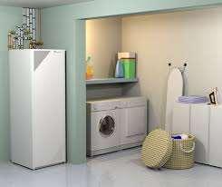
11 rather than a strap-on one, should be used to sense the stored water temperature as it is more accurate. The DHW cylinder should be located within the envelope of the building in a heated space, ideally in airing cupboard or hot press, minimising the heat losses from the cylinder to the surroundings. If the DHW cylinder cannot be located within the envelope of the house it should be brought to the end users attention that the running costs for DHW production will generally be higher. In general Heat Pumps will not carry out space heating at the same time as domestic hot water production. The Heat Pump manufacturer will recommend the domestic hot water cylinder heat exchanger or coil specification. Domestic hot water heat exchangers for Heat Pump systems require a much greater heat exchanger performance as compared to traditional combustion-based heat sources (i.e. boilers). For coil-type heat exchangers, this usually requires a significantly greater heat exchanger area. There are 3 main types of DHW storage cylinders: Integral storage cylinder, where the Heat Pump s heat exchanger is within the same casing with the DHW cylinder; Separate storage cylinder, where the Heat Pump s heat exchanger is outside the casing of the DHW cylinder and Fresh water technology, which is an integral thermal store and the DHW production is done instantaneous, therefore not stored. 5. Electrical requirements All electrical work to be carried out is to be in compliance with current electrical regulations i.e. RECI standards and completed by a RECI certified installer. On completion of the electrical work the home owner should be provided with a RECI Certificate/Commissioning form stating that all work was completed in accordance with the current legislation. Heat Pump manufacturers to provide all relevant data, installation manuals, load requirements, etc. to make sure that the Heat Pump and all heat pump related equipment is installed in accordance with the manufacturer s specification and current electrical regulations. It is recommended the installation of electrical meters for the outdoor and indoor units, if applicable, to separate the heat pump electrical usage from the domestic electrical usage. 6. Commissioning & Maintenance 6.1 Commissioning Heat Pump systems shall be commissioned according to the manufacturer s instructions and the system design parameters and an Energy Label for the combination system heating & DHW should be provided for the end user. The designer/installer of the system should provide the designer/installer sign-off form
12 making sure that all relevant data is made available for the completion of the final BER assessment. Heat Pump Association of Ireland will be issuing a HPA Passport enabling each manufacturer to certify their installers, confirming therefore that they have been trained & certified to install their product in conformity with manufacturer s specification and corresponding Irish legislation. A handover package to home owner has to be made available, so the home owner can have a basic understanding of the system installed. This should include the end user s guide for the heat pump, heating, DHW and controls installed. Also is recommended the commissioning form to be part of this package stating all parties involved in completing the installation i.e. mechanical contractor, electrical contractor, F-Gas refrigeration engineer (if applicable), commissioning engineer, etc. alongside with the service/maintenance recommendations. Label indicating the flow rate required by the Heat Pump shall be fixed on the manufacturer s equipment. The heat pump and its associated pipework shall be flushed and to all air removed from the installed pipework. The installation shall be physically inspected and commissioned by a suitably qualified engineer, trained and registered with the manufacturer to ensure the system is installed and operates as per the manufacturer s specifications. As part of the Heat Pump commissioning the engineer has to make sure that the Heat Pump is working in accordance with the provided performance parameters, designed flow & return temperatures are being achieved for both heating and DHW production. It is considered good practice, the use of a pre-commissioning form provided to the installer and confirmation that all recommended pre-commissioning work has been completed prior to the commissioning engineer attending site. For Air-to-water heat pumps the commissioning engineer has to ensure that the minimum air circulation is being met by checking the location & installation details of the outdoor unit and if changes are to be made, recommendations are to be given to the installer/end user for these to be completed. If the Air-to-water heat pump used is Monobloc type to ensure that an anti-freeze fluid mixture been used that will protect the Heat Pump hydraulic components in freezing conditions in the event of a power failure. 6.2 Maintenance Heat Pumps can operate for 20 years or more, but they do require regular scheduled maintenance. The installer should leave written details of any maintenance checks you should undertake to ensure everything is working properly. Consultation should be made with your supplier for exact maintenance requirements before you commit to installing a Heat Pump. Please see below some of the typical maintenance requirements for indoor units and outdoor units, where applicable: Indoor units: Cleaning the unit Checking heating & DHW on/off temperatures Electrical connections safe & sound Water filter, water pressure and expansion vessel pressure 3 way valve changing from CH to DHW

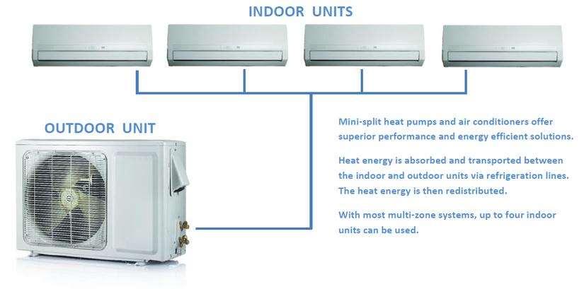
13 Switch box Booster heater cutting on/off - if applicable Outdoor units: Cleaning the unit, especially the coil as dirt, cobwebs, etc. can have an effect on the efficiency of the heat pump; the fins are to be cleaned with soap & water, no other chemical substances Fins to be straightened, if necessary Electrical connections safe & sound 2. HEAT PUMP TYPES 2.1 AIR SOURCE HEAT PUMPS Air-to-water, Air-to-air and Exhaustair Air source heat pumps work by using electrical energy to extract energy from the outside air and transfer it inside as heat, which makes it an efficient way of heating. There are two main types: I. AIR-TO-WATER where the extracted energy from the outside air is being transferred through a heat exchanger to water; these systems can provide full Heating & DHW production II. AIR-TO-AIR Heat Pumps where the extracted energy from the outside air is being transferred through a heat exchanger to air; these systems can provide full Heating. III. EXHAUST AIR Heat Pumps where extracts heat from the exhaust air of a building and transfers the heat to the supply air, hot water and/or hydronic heating system The main components are as follows: Evaporator: A heat exchanger that absorbs heat from the surroundings, (the outdoor unit).
14 Compressor: Reduces the refrigerant gas volume by compressing it, causing the gas temperature and pressure to rise, and pumps the refrigerant around the pipework/system. The compressor may operate as a fixed- or variable speed system. Condenser: A heat exchanger that releases heat to the surroundings, (the indoor unit). Expansion valve: Allows the refrigerant condensate (liquid) to expand, lowering the pressure and temperature. Coil/pipework: Continuous, closed-circuit tubing through which refrigerant flows and heat transfer occurs. The pipes generally have fins to increase the surface area for the heat exchange process. Refrigerant: The compound that circulates through the heat pump system in liquid and gas state, alternately absorbing and releasing heat Reversing or 4 way valve: Changes the direction of flow of the refrigerant to reverse the heat pump function from heating to cooling or vice versa. The reversing valve also allows the pump to switch into defrost mode Fan(s): Draws air across the evaporator coil (for heat extraction) and moves air away from the condenser coil (for heat distribution/removal). There are five main processes in the cycle: 1. In the evaporator (outdoor unit), low-pressure, low-temperature liquid refrigerant absorbs heat from its surroundings and evaporates, converting to a gas state and absorbing energy as it does so (latent heat of evaporation). 2. It passes through the compressor where the low temperature gas is reduced in volume, resulting in a rise in both temperature and pressure. 3. As a heated and high-pressure gas, it passes through the condenser (indoor unit) where the gas condenses (latent heat of condensation) with a release of heat to: the water flowing on the other side of the heat exchanger and using a circulating pump we transfer this energy into the heating & DHW system Air to water system. or to the air surrounding the coil, as a fan moves the warmed air away from the coil it s distributing the heat it throughout the indoor space Air to air system. 4. Still under pressure, the cooled refrigerant, now in liquid state, passes through the metering device, where rapid expansion results in a reduction in pressure. 5. In the low-pressure, low-temperature state, the refrigerant flows back into the evaporator, and the cycle is repeated. The efficiency of an Air Source Heat Pump system is varies along with the temperature differential between indoor and outdoor air and the require flow temperature. A Heat Pump s rated efficiency/cop is for an outdoor temperature of 7 C and flow temperature of 35 C, so when designing a system it is important to understand how it will perform at lower temperatures. When the Heat Pump is in heating mode, as the difference between outdoor temperature and desired indoor
15 temperature increases, the efficiency of a Heat Pump system decreases. Different Heat Pumps will perform very differently at sub-zero temperatures some may keep performing down to -25 C while others will struggle at temperatures below freezing. Another temperature-related factor that can impact on efficiency is the extra energy that may be required for defrosting at low temperatures. At just a few degrees Celsius, any water vapour in the air will start to condense and freeze onto the evaporator (outdoor heat exchanger) coil. This will disrupt the heat flow, and the coils must be de-iced for heating to be able to continue. Certain Heat Pumps don t require a buffer vessel as part of the heating system but they do require a minimum volume of water to be contained within the pipework, to allow the defrost cycle to happen i.e ltr. For optimal Heat Pump efficiency, a system must be correctly sized to minimise energy losses that occur during the defrost cycle. The defrost cycle is necessary to remove ice build-up on the evaporator coil. Ice build-up occurs at around at 0-4 C (especially in high humidity), when any water vapour in the air will start to condense and freeze onto the evaporator (outdoor heat exchanger) coil. This will disrupt the heat flow, and the coils must be de-iced for heating to be able to continue. To remove ice build-up on the coils, most Heat Pumps have a defrost cycle where the system switches into cooling mode (taking some heat from inside), which could effectively cool the room. Some systems have a closed loop cycle to use waste heat from the motor/compressor to defrost the coils. While this is occurring, no heat is supplied to indoors. The defrost frequency and performance are critical to Heat Pump efficiency. Undersized Heat Pumps will need to defrost frequently in low ambient temperatures, reducing the system s ability to reach and maintain set point. If the defrost cycle operates too frequently or if it does not operate often enough, it will not provide sufficient heating, and Heat Pump operation will be compromised. The defrost cycle control is either: a time-temperature defrost starting and stopping at pre-set times (30-, 60- or 90-minute intervals); or on-demand defrost, which is generally more efficient because it operates only when it detects frost build-up on the outdoor coil by monitoring air and coil temperature, outdoor airflow, pressure differential across the coil and refrigerant pressure. Most ASHP have an on-demand defrost control. Systems that include a dry-coil defrost cycle briefly run the outdoor fan at maximum speed before the system starts to heat again, to remove any water that may still be on the coil fins and would immediately refreeze. This operation can be seen by water vapour blowing from the outdoor unit before the heating cycle resumes. Correct Heat Pump sizing is critical to efficiency and performance. The unit should be selected for the heating load that is required. If the Heat Pump is too small or too large, the system will use more energy than necessary, increasing running costs and losing efficiency, and heating/cooling requirements may not be met. A correctly-sized Heat Pump system, when compared to a poorly-sized system, will have:

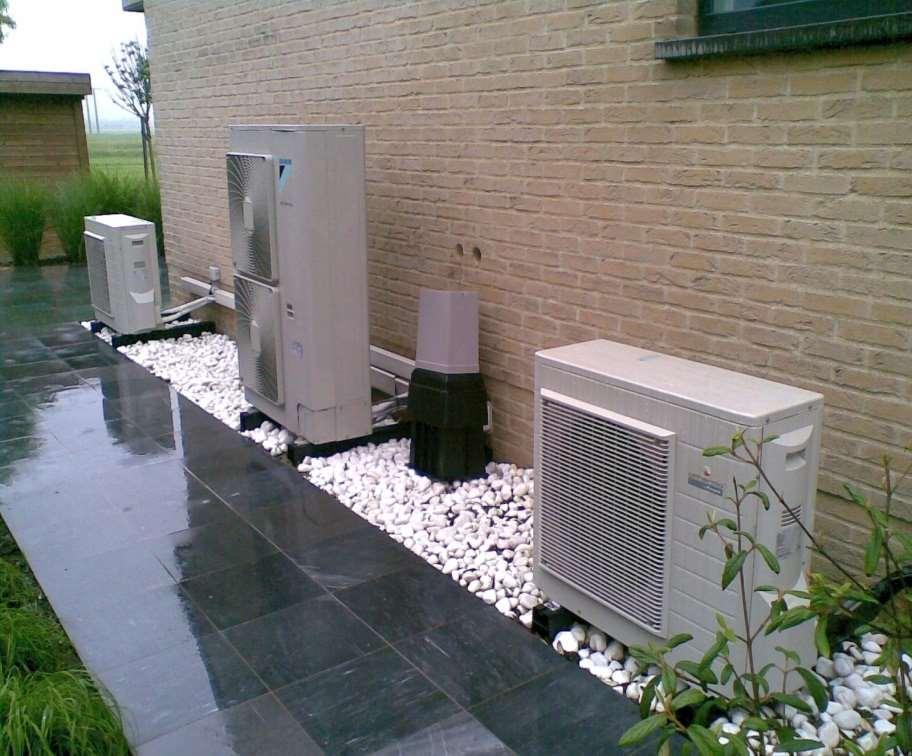
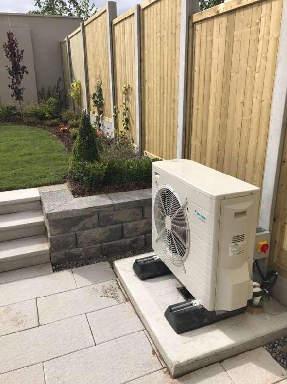
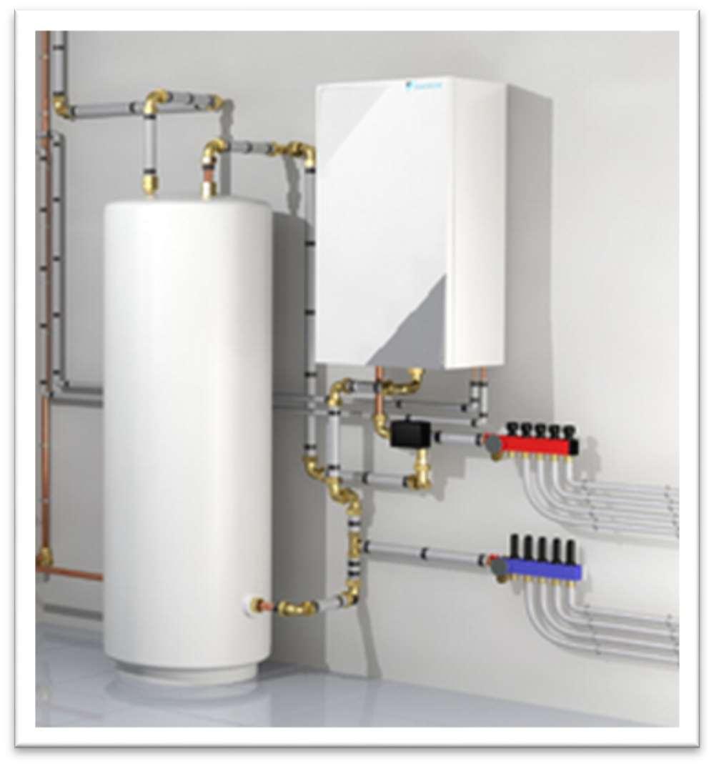
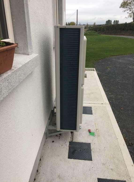
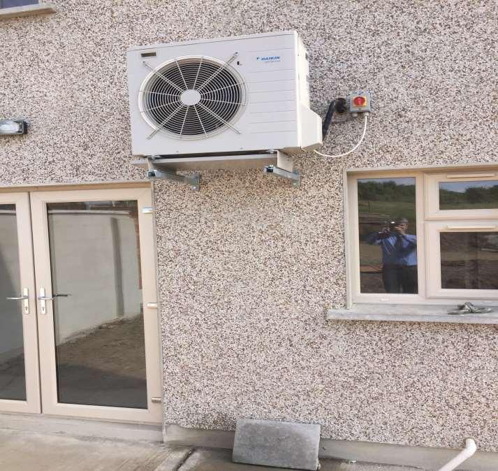
16 shorter total compression run times and start on/offs lower frequency operation speeds reduced defrost mode running all the above translated in overall lower heat pump running costs. Installing an undersized Heat Pump unit will significantly increase running costs, to the extent that the extra annual running cost will be more than the cost of installing a unit that is the next size up. Where a large-capacity Heat Pump is required or the space being heated is large, installing two smaller units may give better heat distribution within the space and better control than the large single unit. There are two main types of Air-to-water heat pumps: MONOBLOC where the heat exchanger to transfer the energy from compressor to water is built by the compressor in the outdoor unit. This type of Heat Pump require water based Flow & Return connections SPLIT type where the heat exchanger to transfer the energy from compressor to water is built by the in the indoor unit. This type of Heat Pump requires F- Gas Refrigerant pipe work connections. In this case we could have a WALL HUNG INDOOR unit and an INTEGRAL INDOOR UNIT. Typically the MONOBLOC & SPLIT with Wall Hung unit connect to a Separate DHW Cylinder and the SPLIT with Integral unit has the DHW cylinder built-in the indoor unit. Both type of Heat Pumps Monobloc & Split are widely used each of these having the own benefits, making either/or the other the preferred unit mostly driven by installers. Please see below recommendations when locating the outdoor, indoor and cylinder, also some installations examples: There are a few important things to be considered when deciding on the location of the outdoor unit and indoor unit/cylinder: 1. OUTDOOR UNIT: most important is that proper circulation of air all around the unit being provided; lack of this will cause lower efficiencies and too often defrost cycles resulting in high running costs - this to be done on every installation in accordance with manufacturer s specifications.


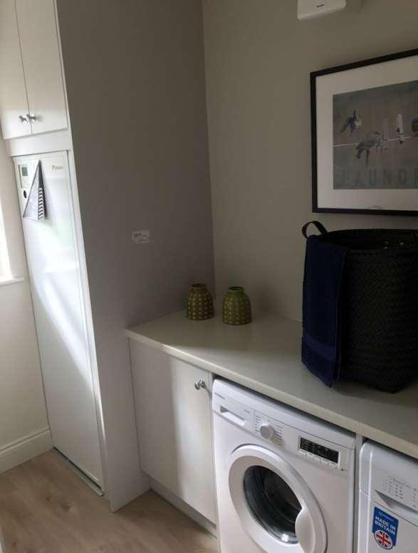
17 2. The OUTDOOR UNIT should ideally be located in close proximity of the dwelling and by doing this we are ensuring that we are minimizing the pipe run between the outdoor and indoor/cylinder, therefore reducing the pipe heat losses. Is to be taken in account that especially during winter time condensation is going to be generated from the evaporating coil, so provisions are to be made that the condensate is being collected and drained away. The installer is to ensure that under no circumstances the condensate will be draining on the foot path as this can freeze during winter, creating a hazard for the home owner. 3. The OUTDOOR UNIT can be mounted at ground level feet ensuring that a minimum gap is maintained between the ground level and the bottom of the unit, so no debris can be accumulated underneath the unit. If the unit is installed at height, it to be confirmed by the manufacturer what is the maximum permissible height and what are the implications regarding the future service and maintenance of the unit. 4. The OUTDOOR UNIT can create a certain level of noise to be confirmed by each manufacturer and in certain conditions, depending on the site limitations is it to be agreed the suitability of the installation in close proximity of bedrooms. Most heat pump manufacturers have a quiet level function that can be activated, limiting the noise produced within certain time schedules. 5. The INDOOR UNIT and CYLINDER or INTEGRATED INDOOR UNIT that contains the cylinder, should be located as centrally to the dwelling as possible, allowing a good balancing in the heating and DHW distribution pipework. This should be installed in accordance with the current Heating & Plumbing Regulations ensuring servicing and maintenance space is provided around the unit, in accordance with manufacturer s specifications. Please see below some examples of OUTDOOR and INDOOR/CYLINDER installations:


18 Air-to-Air Systems: Air-to-Water Systems:
19
20
21 Exhaust Air Heat Pumps - EAHP Overview Used in air-tight, low energy homes and apartments, where ventilation is a must and the major heat loss of the dwelling is due to (the necessary) air changes, EAHP technology was developed in Denmark and Sweden in the early 70 s during the oil crisis. Air is drawn through ducts to the heat pump usually from the bathrooms, utility and kitchen areas. The cold waste air is discharged to outside through another duct, and condensation to a drain. Not only that, the additional heat generated internally from lighting, people and domestic appliances is also utilized through heat recovery. These heat pumps are normally used in new low energy homes and rarely suitable for retro-fits. Heat recovered from the exhaust air may also be augmented by additional outside air drawn into the machine. Heat is transferred to the hot water system and the heating system via radiators, floor heating or sometimes to an air heating battery in a supply air heating system. Types There are three main types: - 1. EAHP units that provide space and water heating with inlet air ducts only outside air is drawn into the building through special air inlets fitted with filters and volume dampers located in the outside walls of living areas and bedrooms. As you can only obtain a limited amount of heat from the building s waste air, additional energy may be taken into the machine from a supplemental air supply. EAHP with Inlet only ducting type 1

22 Specialised air inlets with filters 1 2. EAHP units that provide space and water heating with both supply and exhaust inlet air ducts EAHP with supply and exhaust ducting - type 2 3. Units that heat hot water only from ventilation often from the room they are located in, or adjacent bathrooms. These usually feature an additional built-in heat source suchas an electric back-up immersion but may also have heating coils for interconnectuion to the heating system, solar thermal or even both.

 EAHP must not be installed in buildings with uncontrolled ventilation infiltration, open fireplaces, poor insulation or a heat demand that exceeds the output of the chosen unit from")
23 EAHP Hot Water Only - Type 3 Points to Note The heating systems for EAHP types 1 & 2 are usually radiators or floor heating and are similar in nature to those used with air to water or groundsource heat pumps in that they are usually low temperature systems with the UFH running in the 28 to 40 C range and radiators to max 55 C. Those systems are also usually variable in temperature with the load determined by weather compensation. Important Design & Installation Points 1. The (types 1 & 2) EAHP must not be installed in buildings with uncontrolled ventilation infiltration, open fireplaces, poor insulation or a heat demand that exceeds the output of the chosen unit from the heat pump process alone. Shortfalls in energy needed may in those cases be provided by supplemental electric heating for instance leading to customer complaints about high running costs. 2. Ventilation ducting systems need to be properly designed to ensure sufficient air flow to the heat pump. This is a critical item without sufficient air flow the EAHP will not function properly. 3. The extract air, from which the EAHP extracts energy as its heat source, must be well insulated if not running within the heated fabric of the building (passing through attics etc.) 4. Setting fan speeds and balancing of air flow is critical for correct operation, conservation of energy and to minimise noise. 5. Use of attenuators or acoustic flex ducting at the ventilation entry / exit points on the heat pump may need to be considered.
24 6. Proper ducting systems must be used and to minimise required fan power and ensure correct airflow with reduced noise. Rigid metal, plastic or a bespoke system with manifolds / foam EPE ducting should be considered. 7. Where flexible ducting is used, often for instance from the EAHP to the ducting spigots from the ceiling overhead, bear in mind access to the jubilee clips for future replacement of those ducts i.e. the ends of the flexible ducting should not vanish into the ceiling or plastered walls! 8. The discharge or waste air from an EAHP can be very cold (from 1 and often as low as -15 C) so it is critically important that that run of ducting is to be insulated with diffusion tight insulation or to be made from EPE foam. ANY Gaps in insulation will lead to condensation on ceilings or water running down the discharge duct and into the machine causing damage. 9. A correctly plumbed drain is required from an EAHP for disposal of condensate and potential discharge from the safety valves tundish. 10. EAHPs are usually located within the house or apartment, in a hot press, utility room or even kitchen. They should NOT be located in a garage or outhouse! 11. The manufacturers installation guidelines should always be closely adhered to and installers should be trained by the relevant manufacturer or agent for product specific installation procedures. 12. The end user should be instructed on correct operating use and routine maintenance items such as air filter changing etc.

25 Typical Exhaust Air Heat Pump for Heating & Hot water
26

27 2.1 GEOTHERMAL Heat Pumps Ground source closed and opened loop Overview With the aid of a ground source heat pump, solar energy stored in the ground can be collected and used to heat your home. Often referred to as geothermal heating, the heat collected is mostly from the sun in fact and not the earth s core. Warmth builds up underground from the first days of spring when the surface temperature of the earth starts to increase, to high summer, when the rays of the midday sun penetrate down into the ground. Warm rainwater also permeates the upper layers of the ground. By the time the autumn leaves are falling, there s enough energy stored in the ground to heat up your house throughout the coldest winter. A heat pump captures and upgrades this naturally occurring warmth, so even if the summer seems wet and cool, it can still provide enough energy to maintain a comfortable indoor temperature throughout the coldest winter. Ground source heat is pure, stored, solar energy that is retrieved from deep in the ground with a bore-hole, the bottom of a lake or a few metres below the lawn. The most suitable is determined by the house's energy requirement, the existing heating system and the plot. The system provides a convenient supply of heat and hot water, and can also provide cooling during hot days. The tubing called a collector which is buried in the garden or placed in a borehole contains a mixture of water and antifreeze. (there are also DX or Direct Evaporating heat pumps detailed in a separate section).
28 Types of Ground Source Heat Pumps (GSHP) There are three main types of GSHP: Brine to Water the most commonly used type takes heat energy from closed loops buried in the soil, placed in a lake or through a borehole probe. Water to Water Open-Loop System This type of system uses well or surface body water as the heat exchange fluid that circulates directly through the geothermal heat pump system. Once it has circulated through the system, the water returns to the ground through the well, a recharge well, or surface discharge. This option is practical only with an adequate supply of relatively clean water, and if all local codes and regulations regarding groundwater discharge is met. DX (direct exchange) or Direct Evaporation These heat pumps use copper or aluminium pipes filled with the refrigerant gas and normally coated with a PE plastic layer to directly absorb heat energy from the earth in horizontal arrays (Ground source heat pumps (GSHP) work by using electrical energy to extract energy from the ground or ground water and transfer it inside as heat, which makes it an efficient way of heating. There are two main types/three main types I. GSHP CLOSED LOOP where the extracted energy from the ground is being transferred through a closed loop either horizontal or vertical pipe arrangement using a brine/glycol mixture to harvest the energy from the ground II. GSHP CLOSED LOOP Direct Evaporating or DX where the extracted energy from the ground is being transferred through a closed loop either horizontal or vertical pipe arrangement using a refrigerant to harvest the energy from the ground III. GSHP OPENED LOOP where the extracted energy from the ground is being transferred through an opened loop either horizontal or vertical pipe arrangement using the energy from the ground water) THE ABOVE 2 CLSIFICATIONS TO BE AGREED BY HPA MEMBERS! The three main components are, as follows: 1. The collector (or loop) - this extracts energy from the ground. There are several different types and layouts of collectors, and these are described later in this chapter 2. The heat pump - converts the energy from the ground to usable energy in your home for heating or cooling and DHW 3. The distribution system maintains your home at a constant temperature by providing heat or cooling through radiators or underfloor heating.
29 There are four main types of CLOSED LOOP brine/glycol mixture collectors: horizontal, vertical, slinky and pond loops see figure below: General Points to note Unlike gas and oil boilers, heat pumps are generally designed deliver heat at lower temperatures over much longer periods. During the winter they may need to be on constantly to heat your home efficiently note this does not mean the compressor, the engine of the heat pump is always on, but the control systems strategy usually will be able to call on it as necessary to maintain the balance of heat required for the building versus the temperature outside. You may also notice that radiators won't feel as hot to the touch as they might do when you are using a gas or oil boiler which is firing heat into the building in timed bursts. You will be more comfortable allowing the heat pump to calculate and maintain the warmth (and perhaps cooling) of the building and production of hot water rather than the occupants trying to do this with switches or timers. Note that whilst pipework design and principles may seem to be broadly similar to the installation of an oil or gas boiler, there may be some differences. For instance, a buffer tank may be required, or else a strategy for the disposal of heat as the heat pump s work-load is satisfied and it waits to switch off for a short period. Heat pumps with fixed speed compressors as a rule will need a buffer tank sized at 20L per kw output, inverter or variable speed machines will be able to cope with much smaller buffer tanks. Usually, the heat pump manufacturer will provide design guidance and particular recommendations for their systems layouts and these as a rule should be closely studied and adhered to. Water travelling through the heating system will be at a lower temperature than oil/gas systems so less energy can be passed through smaller pipes; for this reason, it is critical that careful attention is paid to the system design and pipe dimensions. It has been said the three most important things in heat pumps are circulation, circulation, circulation! Note also that there is a relationship between the size and output of a heat pump to the size of hot water tank selected. The hot water tank will generally either be a tankin-tank type with some buffer volume or at least have a very large heating coil or heat exchanger. Most standard or existing cylinders in retrofit situation will not be suitable for a heat pump. It is important again, that the manufacturers advice should be closely adhered to. The choice of a GSHP means that there is no outdoor machinery such as with an Air to Water heat pump. In cold weather the ground temperature will give higher efficiencies over air to water and there is energy lost to defrosting. Another advantage of the GSHP is that especially when used with a borehole, they can provide free cooling usually used in conjunction with floor heating or fan coils. Unwanted solar gain is transferred to the rock where it may be reclaimed later.
30 Location of plant Most modern ground source heat pumps for domestic dwellings are quiet enough and built to an appliance styled finish that it is usually best practice to locate the heat pump in the utility room or somewhere convenient within the house or building to be heated. Many are even available with the hot water tank integrated into the same fridge-like casing saving further on installation time and adding to efficiency. Locating heating equipment (and hot water cylinder) in a remote shed or garage will incur a loss of efficiency and higher installation and running costs of course! Horizontal Collectors When collecting heat from a horizontal field array of pipes the area selected will need to be approximately 2 ½ to 3 times the floor area of the building being heated and are normally placed one metre below the lawn and at least 1 to 1.5M spacing. If there is not enough room for a horizontal array, then use of a borehole or energy-well should be chosen instead. The fluid circulated in the pipes is often referred to as brine but is in fact a mixture of either ethylene glycol (or ethyl alcohol) and water. Care should be taken to ensure that this must be perfectly clean during the filling, mixing and flushing procedures. Pipes should have open ends taped or blanked off during laying and prior to connection at the distribution manifolds. All ground source heat pumps whether connected to horizontal or borehole collectors should be fitted with either a brass Y-strainer or Filter-ball-valve to ensure no dirt can enter the heat pumps heat exchanger. In Ireland the soil 1 metre below the surface is about +10 C or even warmer all year round; the incoming collector fluid will usually not fall below +5 C inbound in winter. A correctly functioning heat pump should have a temperature difference or delta T of 3 to 5 C. For example, the measured brine temperature in could be 5 in and 2 out whereby inside the heat pump s heat exchanger the temperature will be some 10 C lower than the brine out figure, -8 C. For this reason, it is required that the brine mix is protected from freezing with a mixed ratio of approximately 1/3 antifreeze to 2/3 water and a reading of -17 measured by the commissioning engineer. Placing the collector field deeper than around one metre in Ireland does not give any advantage, in fact the soil will take longer to recover heat that would trickle inwards from sun and rain. It is often advantageous in new builds to place the collector field underneath a percolation area dug for the waste water discharge to save space and excavation time. Consideration must be given to the soil type and calculations of hose lengths need to be determined by the system provider or suitably qualified installer. Wet ground will be richer in heat versus sandy or fast draining stony soil. When the latter types are


31 encountered it will usually be necessary to use additional plastic loops to compensate. Testing Procedures Prior to filling the collector system with the antifreeze mix it is essential that the pipes are flushed of air and filled with water and pressure tested to 3 Bar and the whole array inspected visually. Use of compressed-air for testing is not acceptable as any very small leaks in joints would not show up as water cannot be compressed, the pressure gauge on the test pump will register an immediate drop in case of any leak. It is good practice not to have any joints in pipes left under the soil and when there are multiple loops (there usually are) it is strongly advised to use a purpose built manifold chamber for ease of future servicing and inspections. If jointing or repair is required it is best practice to use plastic fuse-welding with appropriate fittings. Once back filled with soil, if a leak occurs - for instance damage from a digger, it will be virtually impossible to locate and a new loop will need to be dug in and installed. The collector field s operating pressure is very low; normally in the range of between.5 to 1.5 bar and leaks are an extremely rare occurrence once care is taken during the fitting process. Manifold chamber from above Manifold chamber with lid prior to back-filling


32 Plastic polyethylene pipes, most commonly 40mm in diameter are laid in trenches, or excavated ground for covering later, or even below the percolation area from a septic tank or waste water treatment plant. Care must be taken that the collector piping is laid joint free in continuous rolls and obviously free from contact with sharp rocks or stones before back-filling. waterproof closed cell insulation. Care must be taken where the collector piping passes underneath paths, walls and foundations at the entry point to the building as there is potentially risk of ice damage in very cold weather. The pipes must be insulated at those points in Three-loop collector field for a large house no pipe joints in the field, only inside the manifold chamber


33 A ground source heat pump fitted indoors with an integral Hot Water cylinder Closed loop boreholes used for heating and cooling are most commonly drilled 150mm in diameter. A steel casing is fitted by the drillers to stop the loose overburden and soil from falling into the well. Into the well the driller inserts a U-bend or probe most commonly made from one jointless extrusion of twin 40mm pipes certified to SDR11 standard and normally with a 3.5mm wall. There are also four-pipe systems of two interlocked smaller U- Bends, but as there is so much heat in the borehole, this is not twice as good as some people think, but only about 5% more effective. Unlike water wells, these energy wells are not lined with plastic and it essential that Mini Drilling rig making a borehole in a suburban Dublin house- with a tiny garden, the owner elected to use a borehole as the more aesthetic solution over an air to water heat pump.
34 the probe is inserted before moving the drilling rig, otherwise the well can collapse and probe insertion becomes impossible. Before inserting the probe, it must also be filled with water and pressure tested for leaks. It would incidentally be impossible to fit without filling as the probe would simply float in the water down the well. Borehole depth required will normally be provided by the heat pump suppliers or services engineers calculations, and for bigger properties, multiple holes may be required. There needs to be a minimum distance of 12 to 15M between the energy wells so ne well is not robbing heat from the other. Interconnection of multiple borehole probes is treated in exactly the same way as multiple loops of horizontal arrays a proprietary manifold chamber is strongly recommended over a homemade pit and the fluid or brine is also antifreeze/water filled with protection to at least -17 C. Typically 150M deep energy well will yield 10kW for heating. Shortly after drilling, the water table will settle at its normal level the active depth is from the top of the water downwards. In some countries thick non-setting liquid clay called grout is pumped into the borehole, but water is a better conductor of heat and grouting a hole in Ireland should only be necessary if the hole was not to fill with water or the upper level of the borehole remained empty in the case of a very low water table. To prevent ingress of surface water and possible contamination of water aquifers, the borehole should be fitted with a neoprene cap which fits over the steel casings and is secured with stainless steel Jubilee clips. Location of the energy well should be noted and the well covered with a manhole for future access. If the well head is above the level of entry to the building or manifold chamber, air vents must be installed to allow for venting prior to commissioning.


35 Borehole probe on a turntable to allow unwinding and insertion to the well whilst filled with water. Neoprene borehole sealing cap

36 Anatomy of an Energy Well Lake and river collectors Sometimes it can be convenient to use a lake, river or even the sea as the source of heat for a ground source heat pump. This is often chosen as the sinking of collector loops in the lake is much more cost effective than using boreholes and you are lucky enough to beside such a rich source of energy. Some important points to consider for this is that special calculations will be needed to dimension the collector usually provided by the heat pump distributor or manufacturer. Again, the multiple loops are filled with antifreeze, but the use of non-toxic fluids such as propylene glycol or ethanol is preferred in case of water course contamination. Also, manifold chambers are recommended for connection of the multiple loops used. If the lake is not on private land permissions may have to be sought for its use. Small ponds sometimes can be used, but only if there is enough through put of water from a steam or river to replenish the heat harvested from it.

37 Collector on the shore before sinking with weights to the lake bed for a large Irish period country house. The 5-acre lake supplies the sole source of heat for the 26,000sq. ft. house plus a swimming pool.
, are a type of ground source heat")
38 Manifold chamber for a large lake collector with valves and flow regulators. CLOSED LOOP Direct Evaporating Heat Pumps Overview & Installation detail please see below: Direct Evaporating heat pumps, sometimes known as Direct exchange (DX), are a type of ground source heat pump. They are similar in construction to a brine to water unit but rather than having an evaporator heat exchanger inside the heat pump unit they utilise a network of copper or aluminium pipes, normally coated in PE, laid in a horizontal configuration in the ground in order to absorb energy from the earth. The refrigerant gas on the evaporating/low side of the system is circulated directly through these pipes and absorbs energy directly from the ground. They are slightly more efficient than a brine to water system since there is no intermediary circuit and therefore no losses in transferring energy from the ground to refrigerant gas. As the refrigerant is circulated by the compressor there is no cost associated with this unlike a brine circuit which requires a circulating pump. DX collectors are not suitable for installation in water logged soils as they have the potential to freeze the surrounding soil. Care should be taken when installing in very dry soils to compensate for the lower levels of energy available by installing additional loops.

39 Installation method Direct evaporating loops are generally supplied in a standard length and diameter by the heat pump manufacturer. The collector pipes are laid in a single trench whose width is determined by the number of pipes required to satisfy the cooling load of the heat pump and also by the length of the pipes being installed. The ends of the pipes originate and terminate at a common position where they are brazed together in a manifold. The flow and return leg off each loop should be a minimum of 500mm from each other and from the adjacent loop. The collector should be designed so that no more than 20w per linear metre of pipe is being extracted. The collector pipes should also be laid in a bed of fine sand (approx mm above and below the pipework). The main flow and return pipe from the manifold position to the heat pump must be laid in a trench connecting both positions. These pipes should be further protected by a sewer pipe or heavy gauge hydro-dare as they are often routed under driveways etc. and so are more susceptible to damage. The pipes are also copper or aluminium and the total length of the distance between heat pump and manifold should not exceed 30m to allow stable operation of the refrigeration circuit.

40 Correct procedure for collector installation 1. The correct number of loops required to satisfy the cooling load of the heat pump should be determined and an area designed to accommodate the loops should be excavated to a depth of at least 0.8m. 2. The narrow end of the collector should be kept closest to the house and a position for the manifold should be marked at the centre point of this end. 3. A 50-75mm bed of sand should be laid on the base of the excavation. 4. The first loop should be rolled out, starting at the manifold position and following the outer edge of one side of the collector. At the halfway point of the collector loop the pipe should be returned to the manifold position, maintaining a minimum distance of 500mm from the other pipe. 5. Continue to roll out additional pipes until all loops are laid taking care to maintain the minimum distances between loops. 6. The main flow and return should be laid between the house and manifold. This trench should remain at least 0.8m deep until it enters building housing the heat pump. At this point the distributor and manifold should be set in position with all flows connected to distributor and all returns connected to return manifold. The main flow and return to heat pump should be connected also. 7. It is imperative that no dirt or water enter the pipes during connection as this will affect the performance of the refrigeration system. 8. The pipe to the distributor should rise vertically with at least 200mm of straight pipe before entering the distributor to allow even distribution of the refrigerant through all collector pipes. It is also desirable that each distributor tail be at least 500mm long for the same reason. 9. Return Pipes should enter the top of the manifold and then turn down therefore creating a trap to aid in oil return. 10. At this point the collector is ready for brazing with copper rods. It is essential that the entire system be purged with nitrogen to ensure that all air is
41 expelled thereby preventing oxidisation of the internal surface of the pipe. In order to facilitate this a Schrader valve should be brazed to the outlet line to the collector at the point it leaves the heat pump. The return pipe should be covered leaving only a small hole for air/nitrogen to escape. Nitrogen should be purged through the Schrader using a set of gauges connected to a nitrogen bottle at a rate just sufficient to create a positive pressure of 2psi in the pipes. 11. All joints in the manifold can then be brazed using oxy-acetylene and copper brazing rods. When completed the return line at the heat pump should be crimped and brazed. The nitrogen pressure should then be increased to 1.5 times the system standing pressure and pressure tested for at least one hour. All joints should be tested for integrity using a leak detection solution. 12. If the heat pump is in position at the time of collector installation the collector can be brazed to it prior to pressure testing. It is important to purge the system while brazing these connections also. In order to do this, connect the gauge lines to the Schrader valves inside the heat pump, open the expansion valve (if an electronic valve is fitted) and purge with nitrogen as before. 13. The collector area can then be backfilled, firstly filling in the 50-75mm of sand cover then adding the soil that was excavated previously. 14. Once it has been confirmed that the system is leak free you can begin to vacuum the system using a vacuum pump. This reduces the pressure in the pipework below atmospheric pressure allowing any moisture contained within the pipes to boil and be extracted from the system along with the air inside the system. 15. The system is then ready to be charged with refrigerant of the type and quantity required by the manufacturer. 16. A manhole should be placed around the manifold area taking care not to place any weight on the pipework. A manhole can consist of a block built structure or a formed concrete or plastic ring. Further installation practices to follow: Refrigerant carries the oil which lubricates the compressor with it as it travels. As this oil travels quite a distance in dx system, it is important that sufficient care be taken to allow for oil return within the system. Failure to do so can result in compressor damage. To cater for oil return the following should be considered at design stage - Pipework between the heat pump and collector should be as short as possible with a maximum distance of 30m allowable - The collector area should be level or have a slight gradient back towards the manifold and heat pump
42 - If a collector is more than 2m below the level of the heat pump it is important that oil traps be fitted at the bottom of the section where the pipe begins to rise. - A collector should not be situated any more than 4m below the heat pump. All joints should be cleaned with an emery cloth prior to brazing to remove the oxidisation coating on the pipes and ensure a good quality braze. Points to note: A DX heat pump is charged with refrigerant on site. This is unlike a brine to water or water to water system which normally come precharged. A good working knowledge of refrigeration is essential when installing a DX system as specific conditions on site can affect the charge required. You must be F-gas registered to work on the refrigerant charging of a DX heat pump When backfilling a collector area it is important that no machine should enter the collector area until the soil has been filled to original ground level or that at least 0.7m of cover be placed on top of pipework. Care should be taken not to drop any large rocks onto pipework during backfilling Some DX units are available with R290 refrigerant (propane). Appropriate care must be taken with this refrigerant as it is flammable. When releasing nitrogen from a system following a pressure test it is important to never vent in an enclosed space. Nitrogen will displace the air and can lead to asphyxiation, as Nitrogen occurs naturally in the atmosphere excessive levels are not detectable by humans. Measures should be taken to vent the gas to outside and that sufficient ventilation of the area be provided. In no circumstances is it allowable to discharge refrigerant to atmosphere while commissioning, decommissioning or servicing a heat pump

43 OPENED LOOP Water Source Heat Pumps Overview & Installation detail please see below: All ground source / geothermal heat pumps are connected to the ground via a heat exchanger, usually in the form of a plastic pipe collector array. Usually horizontal and taking up a sizeable area, vertical collectors take heat from a 150 mm hole drilled into rock, the higher density rock giving better heat transfer than the shallow collectors in earth. An alternative is to use ( normally pumped ) ground water as a collector medium, there are multiple risks involved but designed correctly, installed and maintained this offers a low capital investment for high efficiency. Commercially passive cooling from this source offers huge savings on running costs and capital investment on equipment. In this section no reference is made to the delivery side, as this is covered elsewhere, but with any heat pump the design setup should run the delivery sideas cool as possible. Always follow best practice and manufactures specific guidleines. Examples of open loop sources. 1. Shallow wells from underground water sources 2. Reservoirs lakes, streams and rivers i.e. surface water 3. Heat recovery from plant and process, e.g. extra-large water tanks on dairy farms for pre cooling of milk. Why go open loop? Efficiency is the main reason, as the source temperature rises, so too does the efficiency. Where a well-designed ground collector averages 5 C plus over the heating season, an aquifer may provide 12 C all season long, without any fall off in efficiency as predominately the return water is injected at a different location. Where


44 water wells have been drilled for a domestic supply a secondary use is now the heat source for almost zero extra costs. Geology In limited locations in Ireland there are elevated ground water conditions, this magnifies the efficiency, this is rare but the local geology is well known throughout Ireland as its continually mapped and reported by the drilling contractors of Ireland in their drill logs. From this geology the water quality can be accessed in advance as this may prove to be impractical from an equipment maintenance view point. Equipment: If the water quality is excellent then most off the shelf ground source heat pumps can be used with some protection in the form of particle filters. After that external sacrificial heat exchangers are sometimes used. At this stage the efficiency has now been reduced as a 5 C Delta T is an expected loss across the source heat exchanger, the benefits then need to be accessed with higher maintenance in mind. Dedicated open loop Heat Pumps have a different source heat exchanger specifically designed for ground water, this would typically be a co-axial heat exchanger should. These heat exchangers can handle whatever can go through the pump screen including solids up to 8 mm, the metal is usually Titanium or Cupro-nickel which has significant corrosion resistance over the standard brazed plate heat exchangers which are the most widely used in the heat pump industry. Water quality is the biggest issue and has to be considered immediately that a viable water source is determined. Dedicated open loop heat pump manufacturers will have a specified list of parameters on water quality covering, % solids, chemical resistance, Ph and mineral deposits to name a few. As water temperature increases, the output of the unit will rise, after a trial pumping of the water cross reference the water temperature to the heatpump performance tables, this will determine actual Kilowatt output. This can vary by up to 30 %
45 increase in Kilowatt output. With the same input as for a closed loop collector the energy savings are significant. Installation Guidelines: Needs to broke into 3 categories in line with the 3 options on source below. 1. Shallow wells from underground water sources 2. Reservoirs lakes, streams and rivers i.e. surface water 3. Heat recovery Shallow wells: Shallow is important, in that the depth from where the water is pumped from, directly relates to the pumping power required to get the desired water flow. A guideline of Watts per 10 Kw delivered will ensure low pumping costs. Normally to achieve this, a variable speed submersible is required for optimum performance, where multiple heat pumps are required, variable speed is essential. Installation Procedure 1. Evaluate building load. Select appropriate heat pump and determine flow requirements. 2. Check with local drill in reference to geology and expected depths of water table. If all indications are positive, plans can be made to proceed. 3. Prior to drilling investigate disposal of the return water, is it back to the aquifer ( second well required ) or are there other uses for the chilled water, Farm supply for cattle for e.g. explore options, to add another level of efficiency / secondary benefits. 4. The local driller is the best advisor / designer in much of the design of the extract and disposal well, plus providing a good estimate of water quality. 5. Be 100% sure of the water quantity!!!! At 100% demand for 48 Hr continuous loading is best practice for ensuring reliability of supply. Based on flow rates and well depth choose the lowest wattage pump applicable for the project. 6. Do a 48 Hour test as soon as is practically possible.

46 7. If there is any doubts in the water quality, get a chemical analysis test, cross reference this to the manufactures guidelines, see example below. 8. From the pump test, select the heat pump based on thermal performance charts and water quality. 9. Depending on equipment selection, fit all necessary pump protection and filtration to suit. Follow best installation guidelines for well water installations, safety valves, pressure switches and expansion tanks. 10. Avoid sacrificial heat exchangers if possible ( only really applicable to large scale commercial building loads )and use dedicated open loop heat pumps 11. Dispose of the water as best suits the site, but ideally this should be into a second well back into the aquifer, this re-injection well should be as far away from the production well as is practical. Use the water for other uses if possible, last resort would be to discharge to the storm drains. 12. Ensure that the flow and return pipework are not thermally affecting each other, insulate or separate underground by 1m meter or more. 13. All underground pipework should be buried deeply enough or in some way protected from frost / freezing. 14. Never discharge to public sewers 15. If cooling is used (commercial applications) limit water discharge temperature to 26 Deg C. This is critical to oxygen carrying capability of river water, effecting fish negatively (possibly fatally) and promoting algae growth. This is known as thermal pollution and is legislated for in by the Inland Fisheries. 16. Water is plentiful in Ireland but waste of energy and water itself is not correct. From that point ensure that the water is pumped in conjunction with the compressor running. Where the heating may be active, the compressor may be off as it may have reached its set-point. 17. For heat pump protection its good practice to have a flow-switch to ensure the heat exchanger never freezes, this can result in a failure.


47 Installation Procedure: Lake, Reservoir, Stream river collectors. 1. Evaluate building load. Select appropriate heat pump and determine flow requirements. 2. For the most part, the discharge water is returned to the source it came from, so no real planning or thought required here, nor is clean water being wasted. 3. It s highly likely that the water from any of the sources will require some degree of filtration, often it s the extraction pump that needs protection, as the reality with dedicated open loop heat pumps with co-axial heat exchangers, the pump screen will be the weak link. 4. A vortex pump impellor is less efficient from a pumping perspective but it will tolerate a much higher particle dimension, as well as pulverising any organic matter. 5. Water temperatures from these sources normally range from 5 C to 10 C, any source that has lower winter temperatures than +5 C or is prone to icing should not be used, this is not a viable open loop source at this stage, and a closed loop collector should be considered. 6. Installing directly into a stream or a river is often in-practical due to risk of the pump being washed away. The pump should be installed in a protected concrete perforated chamber adjacent

48 to the water source rather in the flow. Multiple solutions abound and what suits the site has to be engineered often on site. 7. Always use a low wattage pump, as the height of lift is often very low, so a variable speed drive may not be required. Wattage per 10 Kw should be less than 200Watt. 8. If conditions allow it can be possible to use gravity to supply the water, this can be an engineering feat, which is worth accomplishing as pumping power is Zero. For this installation to be viable, obviously the weir has to be higher upstream than the heat pump location. To offset heat exchanger back pressure a height of 5m is normally required. Where fouling is an issue, a filter screen should be arranged to be selfcleaning, these are readily available for water supply projects, these would also be flash flood resistant, and tolerant to animal traffic. 9. Water flow, should be controlled to match the heat pumps requirements, a common error is that the water is free and is allowed to flow full bore. Optimum flow should be regulated to optimise the refrigeration cycle, as well as preventing un-necessary wear and tear on the pipework and heat exchanger. 10. If cooling is used (commercial applications) limit water discharge temperature to 26 C. This is critical to oxygen carrying capability of river water, effecting fish negatively (possibly fatally) and promoting algae growth. This is known as thermal pollution and is legislated for in by the Inland Fisheries. Installation Procedure: Plant or Process Heat Recovery Collectors. 1. Evaluate building load. Select appropriate heat pump and determine flow requirements. 2. For the most part, the discharge water is circulated back to the source it came from as the primary benefit may be the process cooling rather than the heat benefit / needs. 3. Equipment selection is critical in terms of (a) thermal output but more importantly (b) operating limits of the heat pump. Most domestic units are designed to tolerate to 20 C on the source. More specialised equipment will have source temps as high as 40 C. 4. It s unlikely that the water from any of the sources will need filtration, as the process water will be clean and of known quality.


49 5. Pumping power should be negligible, but as always careful pump selection will return better performance. 6. Source Temp Vs Performance: Water flow, should be controlled to match the heat pumps requirements, especially as the temperature rises, follow the manufacturers guidelines, cross referencing outputs versus source temperature. For e.g. a nominal 8 w heat pump can produce 15 Kw at elevated source temperatures of 30 C 7. Identifying suitable heat sources: this is only limited by the engineer s imagination, a thorough site investigation, will explore possibilities. Some examples: Chilled water for vegetable washing. Process cooling water for plastic factory. Distillery, which will have cooling in one half of the plant and steam boilers in the other half. Milk cooling especially where the farm house and dairy are nearby. Mushroom houses, chilled water plant.
Saving energy comes naturally to us.
 Domestic Heat Pumps Saving energy comes naturally to us. Low carbon solutions for heating and hot water The sustainable heating solution for today and tomorrow Home heating with lashings of hot water Whether
FREQUENTLY ASKED QUESTIONS
 HEAT PUMP INVERTER R-410A All-in-one, all year round heating, cooling and domestic hot water supply solution FREQUENTLY ASKED QUESTIONS WANT TO KNOW MORE? AVERAGE ANNUAL CO 2 EMISSIONS Daikin Altherma
Kills bills. How Vaillant technologies reduce home heating bills
 Kills bills How Vaillant technologies reduce home heating bills Energy efficiency is a choice For most people, home heating and hot water systems have always been out of sight and out of mind. But now,
Mechanical Ventilation with Heat Recovery: Designing and implementing a robust and effective ventilation system
 Viewpoint August 2012 Mechanical Ventilation with Heat Recovery: Designing and implementing a robust and effective ventilation system Dr Sarah Price and Helen Brown Summary Mechanical Ventilation and Heat
PRODUCT DATA SHEETS HEAT PUMPS
 PRODUCT DATA SHEETS HEAT PUMPS HIGH-TEMPERATURE BRINE-TO-WATER HEAT PUMP: UNIERSAL DESIGN - MAX. FLOW TEMPERATURE 70 C HIGHER FLOW TEMPERATURES FOR HEATING AND DOMESTIC HOT WATER PREPARATION LOW-TEMPERATURE
recooler HP EQKR HEAT PUMP
 AIR COMFORT AIR TREATMENT 9566 GB 2016.03.17 recooler HP EQKR HEAT PUMP» TECHNICAL CATALOGUE 2 ReCooler HP EQKR Technical Catalogue Content ReCOOLER HP EQKR HEAT PUMP 3 product presentation. 3 applications.
Examples of Heat Pumps in DEAP
 Examples of Heat Pumps in DEAP Q1 2016 1 Contents: 1 Introduction... 3 2 Example 1: Air to water heat pump not compliant with Ecodesign/ Energy Labelling Directives. Listed on HARP.... 4 2.1 Heat pump
Maincor Underfloor Heating UNDERFLOOR HEATING SYSTEMS. Introduction. Overview. Tel: Web: Why use Underfloor Heating?
 UNDERFLOOR HEATING SYSTEMS Introduction Underfloor heating (UFH) is not a new concept; it was brought to Britain about 2,000 years ago by the Romans. Their heating technique was to allow hot gasses from
Zeroth Energy System. Presenter. Date
 Zeroth Energy System Presenter Date Overview Review of overheating in UK homes Review of heat network performance Introduction to the Zeroth concept Key benefits What is a heat pump? Heat Pump - Noun
GEOTHERMAL DESIGN GUIDE
 GEOTHERMAL DESIGN GUIDE BENEFITS OF THE BULLDOG SYSTEM CGC Version CGC Group of Companies Incorporated 2018 CONTENTS INTRODUCTION... 2 CHALLENGES FACING CONVENTIONAL GSHP SYSTEMS... 3 FACTORS WHICH IMPACTS
The products covered by the Regulation can be classified as follows:
 Table of Contents 1. Purpose of the guidelines and disclaimer... 3 1.1. The Regulation... 3 2. Scope... 3 3. Product environmental impacts... 4 4. State of play of legislation... 4 4.1. History of the
Frequently Asked Questions
 Air Source Heat Pumps Frequently Asked Questions Heating that doesn t cost the earth What are the benefits of Air Source Heat Pumps over Ground Source Heat Pumps? There are a number of benefits when using
AIR COOLED HEAT PUMP FOR OUTDOOR INSTALLATION FROM 4,2 TO 35,1 kw
 COMFORT HEAT PUMPS AIR COOLED HEAT PUMP FOR OUTDOOR INSTALLATION FROM 4,2 TO 35,1 kw climaveneta.com COMFORT HEAT PUMPS PERFECT COMFORT AND MAXIMUM EFFICIENCY Air to water heat pump for outdoor installation,
Natural geothermal energy
 Natural geothermal energy ROTEX HPU ground the ground source heat pump that heats with free geothermal energy. Compact, environmentally responsible and uniquely efficient. L A ++ A Scale space heating
Daikin VRV Systems Plugin VE2012 User Guide
 www.iesve.com Integrated Environmental Solutions Ltd Developers of the IES May 2012 Contents 1 - Introduction... 3 The... 3 2 - System Types... 4 2 Pipe Heat Pump Systems... 4 3 Pipe
Code of Practice - Ventilation- Mechanical Extract Ventilation (MEV) + Mechanical Ventilation with Heat Recovery (MHVR)
 + Mechanical Ventilation with Heat Recovery (MHVR)") Code of Practice - Ventilation- Mechanical Extract Ventilation (MEV) + Mechanical Ventilation with Heat Recovery (MHVR) Contractors Requirements & Competency This section outlines the general Standards
Code of Practice - Ventilation- Mechanical Extract Ventilation (MEV) + Mechanical Ventilation with Heat Recovery (MHVR) Contractors Requirements & Competency This section outlines the general Standards
ENCLOSURE COOLING. Glossary
 ENCLOSURE COOLING Glossary Contents INTRODUCTION... 3 TYPES OF COOLING EQUIPMENT... 4 COOLING EQUIPMENT COMPONENTS... 5 ESSENTIAL COOLING S... 8 COOLING EQUIPMENT ACCESSORIES... 13 EQUIPMENT THAT NEEDS
Adelaide Homes Design Guide 4 - Winter warming
 Adelaide Homes Design Guide 4 - Winter warming Adelaide's temperate climate means home warming is required during winter. There are many efficient heating systems. The most economical method, however,
your comfort. our world. Altherma Flex Type Renewable heat pump system for every environment
 your comfort. our world. Altherma Flex Type Renewable heat pump system for every environment Outdoor One or more indoor or outdoor units Indoor 1 Domestic hot water 2 Heating 3 Cooling Daikin Altherma
Larch house and Lime house review of systems design and implementation
 Larch house and Lime house review of systems design and implementation This report reviews the design of building services at Larch and Lime houses, Ebbw Vale, and the onsite systems assessment carried
Systems engineering Slide 1
 Slide 1 Overview / Calculation energy flow control / emission distribution building energy use (conditioning boundary) storage generation balance boundary primary energy delivered energy (building boundary)
SPACE CONDITIONING IN COMMERCIAL BUILDINGS Overview
 SPACE CONDITIONING IN COMMERCIAL BUILDINGS Overview As in residential buildings the purpose of mechanical conditioning and ventilation is to maintain air quality and thermal comfort in buildings, with
Institute of Aeronautical Engineering (Autonomous) Dundigal, Hyderabad B.Tech (III II SEM) MECHANICAL ENGINEERING
 Dundigal, Hyderabad B.Tech (III II SEM) MECHANICAL ENGINEERING") Institute of Aeronautical Engineering (Autonomous) Dundigal, Hyderabad- 500 043 B.Tech (III II SEM) MECHANICAL ENGINEERING REFRIGERATION AND AIR CONDITIONING Prepared by, Dr. CH V K N S N Moorthy, Professor
Institute of Aeronautical Engineering (Autonomous) Dundigal, Hyderabad- 500 043 B.Tech (III II SEM) MECHANICAL ENGINEERING REFRIGERATION AND AIR CONDITIONING Prepared by, Dr. CH V K N S N Moorthy, Professor
> > > Heat pump systems. Water Chillers. Dehumidifiers
 > > > Heat pump systems Water Chillers Dehumidifiers Company Profile What is a heat pump? A heat pump is a device that moves heat from one location (called the source ) to another location (called the
Savings and performance worth celebrating! The DHP-AQ new air source heat pump from Danfoss
 Technical article Savings and performance worth celebrating! The DHP-AQ new air source heat pump from Danfoss Air source heat pumps are growing in popularity, thanks to the use of the latest innovations
Starting current with soft starter Fuse protection
 Data sheet LIH 26TE High temperature air-to-water heat pump Max. flow temperature: 75 C Casing colour: White (similar to RAL 9003) Brown-red design screen (RAL 3011) Heat pump for heating purposes for
Daikin VRV Sizing & Simulation Plug-in User Guide
 Daikin VRV Sizing & Simulation Plug-in User Guide IES Virtual Environment Copyright 2015 Integrated Environmental Solutions Limited. All rights reserved. No part of the manual is to be copied or reproduced
Why Vaillant? Home Heating Guide. Because they can reduce our heating bills and our carbon footprint
 Home Heating Guide Why Vaillant? Because they can reduce our heating bills and our carbon footprint Because we re here to help If you have any questions, please call 01634 292300. We can also give you
SECTION 8 AIR SOURCE HEAT PUMPS UNIT 43 AIR SOURCE HEAT PUMPS
 SECTION 8 AIR SOURCE HEAT PUMPS UNIT 43 AIR SOURCE HEAT PUMPS UNIT OBJECTIVES After studying this unit, the reader should be able to Describe the operation of reverse-cycle refrigeration (heat pumps) Explain
b.) Technical Information:
 Technical Information:") Section VI- Strategies a.) Summary: It is important for new construction designers to consider the heating, ventilation, and air conditioning needs within a building. There are many different systems,
Section VI- Strategies a.) Summary: It is important for new construction designers to consider the heating, ventilation, and air conditioning needs within a building. There are many different systems,
Starting current with soft starter Fuse protection. Connection heating Seal of approval MCS (valid until)
") Data sheet LA 16MS Air-to-water heat pump with deflector hoods Max. flow temperature: 58 C Casing colour: White aluminium (similar to RAL 9006) Air-to-water heat pump for outdoor installation with external
Data sheet LA 16MS Air-to-water heat pump with deflector hoods Max. flow temperature: 58 C Casing colour: White aluminium (similar to RAL 9006) Air-to-water heat pump for outdoor installation with external
Technical description. Atec.
 www.thermia.com Thermia Värmepumpar is not liable or bound by warranty if these instructions are not adhered to during installation or service. The English language is used for the original instructions.
EXHAUST AIR HEAT PUMPS EVALUATED FOR NORDIC CIRCUMSTANCES
 Poster P.6.13-1 - EXHAUST AIR HEAT PUMPS EVALUATED FOR NORDIC CIRCUMSTANCES Markus Lindahl, MSc, SP Technical Research Institute of Technology, Energy Technology, Box 857, 501 15 Borås, Sweden; Caroline,
THE HEAT PUMP CHOICE OF PROFESSIONALS
 THE HEAT PUMP CHOICE OF PROFESSIONALS T H E E N E R G Y E F F I C I E N T H E AT I N G S Y S T E M TIME FOR ENERGY EFFICIENT AND INNOVATIVE SOLUTIONS Expectations of consumers are changing. With the high
Residential Heating Boilers
 Residential Heating Boilers BAXI BAXI Luna Duo-Tec GA+ QUALITY HYDRONIC HEATING EQUIPMENT The best in European design & manufacturing giving you warmth, efficiency and total peace of mind. Residential
FACT SHEET 9 Large Air-Conditioning (air-to-air)
") UNEP Ozone Secretariat UNEP Ozone Secretariat Background Material on HFC Management Fact Sheets on HFCs and Low GWP Alternatives October 205 FACT SHEET 9 Large Air-Conditioning (air-to-air). Description
UNEP Ozone Secretariat UNEP Ozone Secretariat Background Material on HFC Management Fact Sheets on HFCs and Low GWP Alternatives October 205 FACT SHEET 9 Large Air-Conditioning (air-to-air). Description
TOTAL SYSTEM EFFICIENCY: AN INTRODUCTION TO CONDENSING BOILERS. David Grassl PE Mechanical Engineer Principal
 TOTAL SYSTEM EFFICIENCY: AN INTRODUCTION TO CONDENSING BOILERS David Grassl PE Mechanical Engineer Principal Boilers are closed pressure vessels that are used to heat fluids -- either water or steam. They
SmartRad Planning Manual
 SmartRad Planning Manual Issue 1 15 April 2010 Dimplex SmartRad Fan Convector Models SRX80, SRX120, SRX140 & SRX180 Applies to models with White Glass, Black Glass and Metal facias Contents 1 Introduction
Geothermal Heating and Cooling Using Ground Source Heat Pumps. Prepared by: Steven Forrester, P.E. Principal
 Geothermal Heating and Cooling Using Ground Source Heat Pumps Prepared by: Steven Forrester, P.E. Principal A Little History on Geothermal and Heat Pumps Lord Kelvin came up with the idea for heat pumps
Products catalogue THERMODYNAMIC SOLUTIONS FOR EFFICIENCY CHALLENGES
 Products catalogue THERMODYNAMIC SOLUTIONS FOR EFFICIENCY CHALLENGES 1 2 3 Heat Merchants have partnered with Energy Panel to offer the most advance technology in Thermodynamic Solar Systems for both residential
Air to water Heat Pump System
 Air to water Heat Pump System 2 The heating and cooling systems of the future! A step in the right direction of reducing pollution and CO₂ emissions The increase of CO₂ and other green house gases is a
BASE LEVEL AUDIT REQUIREMENTS REFRIGERATION SYSTEMS 1. SITE DATA COLLECTION. Business Name. Site physical address (Street, Suburb, City)
") BASE LEVEL AUDIT REQUIREMENTS REFRIGERATION SYSTEMS 1. SITE DATA COLLECTION Business Name Site physical address (Street, Suburb, City) Nature of site / business operation Electricity Supplier Power factor
BASE LEVEL AUDIT REQUIREMENTS REFRIGERATION SYSTEMS 1. SITE DATA COLLECTION Business Name Site physical address (Street, Suburb, City) Nature of site / business operation Electricity Supplier Power factor
UPONOR Ltd. Specification for UPONOR Q&E PEX Shrinkfit Plumbing Systems
 UPONOR Ltd Specification for UPONOR Q&E PEX Shrinkfit Plumbing Systems Reference Page(s) UPONOR Q&E PEX 2 Operating Conditions 2 Pipe Properties 2 Fittings Range 3 Radiator Heating Systems 3 H&C Water
FACT SHEET 9 Large Air-Conditioning (air-to-air)
") FACT SHEET 9 Large Air-Conditioning (air-to-air) UNEP Ozone Secretariat UNEP Ozone Secretariat Background Workshop Material for on HFC HFC Workshop, management: 205 technical issues Bangkok, 20 and 2 April
FACT SHEET 9 Large Air-Conditioning (air-to-air) UNEP Ozone Secretariat UNEP Ozone Secretariat Background Workshop Material for on HFC HFC Workshop, management: 205 technical issues Bangkok, 20 and 2 April
SEISCO APPLICATIONS & DIAGRAMS
 ALICATIONS & DIAGRS A. Seisco Selection Criteria B. Residential Floor lan Diagrams 1. Standard One Story Home Options 2. Standard Two Story Home Options 3. One Story Booster for Quicker Response C. Application
The Corbioli House is a single-family house situated
 All-in-one high-performing system for ZEB houses Maria Ferrara Grant researcher TEBE Research Group Energy Department Politecnico di Torino at Turin, Italy maria.ferrara@polito.it Frederic Kuznik Full
PART I ENERGY EFFICIENCY ACQUIS / DELEGATED REGULATION (EU) 811/2013
 811/2013") Delegated Regulation (EU) 811/2013 of 18 February 2013 supplementing Directive 2010/30/EU with regard to the energy labelling of space heaters, combination heaters, packages of space heater, temperature
Delegated Regulation (EU) 811/2013 of 18 February 2013 supplementing Directive 2010/30/EU with regard to the energy labelling of space heaters, combination heaters, packages of space heater, temperature
Do you want a versatile solution
 Do you want a versatile solution to make significant savings? ESTIA TOSHIBA AIR CONDITIONING RESIDENTIAL HEATING AIR-TO-WATER HEAT PUMP ESTIA hatever you need ESTIA TO MAKE SIGNIFICANT SAVINGS Toshiba
Simply renewable A ++ A +++ ROTEX air-to-water heat pump
 Simply renewable The HPSU monobloc air-to-water heat pump for external installation offers comfortable heat in winter and gentle cooling in summer. System efficiency with Solar*: XL A ++ A +++ * ROTEX
A B C D E F G H I J K L M N O P Q R S T U V W X Y Z
 A B C D E F G H I J K L M N O P Q R S T U V W X Y Z A B C D E F G H I J K L M N O P Q R S T U V W X Y Z Ambient temperature This is the air temperature within a 21 ºC room at any given time. It depends
NEOSYS. AIR TO WATER LIQUID CHILLER kw. AIR TO WATER HEAT PUMP kw. lennoxemea.com
 NEOSYS AIR TO WATER LIQUID CHILLER 200-1000 kw AIR TO WATER HEAT PUMP 200-500 kw lennoxemea.com NEOSYS, winning ENERGY PERFORMANCE The NEOSYS delivers energy efficiency at full and partial load by the
Guidance for Stationary Refrigeration & Air-Conditioning
 Information Sheet RAC 2 - Usage Guidance for Stationary Refrigeration & Air-Conditioning This Information Sheet provides background information about the use of stationary refrigeration, airconditioning
Heat pumps in the UK. a monitoring report GENERAL INFORMATION REPORT 72 BEST PRACTICE PROGRAMME
 GENERAL INFORMATION REPORT 72 Heat pumps in the UK a monitoring report GENERAL INFORMATION REPORT 72 BEST PRACTICE PROGRAMME 1 INTRODUCTION PROJECT SUMMARY This Report summarises the performance monitoring
ErP. ErP READY. The Eco-Design Directive ErP for refrigerator systems and heat pumps. READY
 ErP READY The Eco-Design Directive ErP for refrigerator systems and heat pumps. The EU-Regulation 2281/2016/EU defines the new requirements for refrigerator systems and heat pumps and focuses on the new
Appendix A. Glossary of Common Terms
 Glossary of Common Terms Glossary of Common Terms Absorption chiller A refrigeration machine using heat as the power input to generate chilled water. Adjustable speed drive A means of changing the speed
EXHAUST AIR HEAT PUMPS Mini heat pumps
 EXHAUST AIR HEAT PUMPS Mini heat pumps Last month, we looked at heat pumps which extract their heat from the ambient air outside the house Air Source Heat Pumps. Another source of heat may possibly be
Products catalogue THERMODYNAMIC SOLUTIONS FOR EFFICIENCY CHALLENGES
 Products catalogue THERMODYNAMIC SOLUTIONS FOR EFFICIENCY CHALLENGES 1 1 2 3 Once again, the Energy Panel team has put all their excitement and enthusiasm to create this new publication. We want to make
COMMERCIAL HVAC SYSTEMS Water Source Heat Pump Systems
 COMMERCIAL HVAC SYSTEMS Water Source Heat Pump Systems Technical Development Program Technical Development Programs (TDP) are modules of technical training on HVAC theory, system design, equipment selection
Efficient heating that won t cost the earth
 Product Range Guide Efficient heating that won t cost the earth CTC is an international manufacturer of innovative renewable heating solutions. For over 90 years our ranges of high performance products
EVALUATION OF ALTERNATIVERS TO R404 THE MOST COMMON REFRIGERANT IN SWEDISH GROCERY STORES
 EVALUATION OF ALTERNATIVERS TO R404 THE MOST COMMON REFRIGERANT IN SWEDISH GROCERY STORES Ola, Gustafsson M.Sc. a *, Lennart Rolfsman M.Sc. a, Sara Jensen B.Sc. a, Markus Lindahl M.Sc. a, a SP Technical
COLD STORAGE WAREHOUSE, USING DIRECT EXPANSION AMMONIA REFRIGERANT Ray Clarke ISECO Consulting Services Pty Ltd
 COLD STORAGE WAREHOUSE, USING DIRECT EXPANSION AMMONIA REFRIGERANT Ray Clarke ISECO Consulting Services Pty Ltd Abstract This paper presents the design approach adopted for the expansion of a large existing
HFCs or the Old Refrigerants - what is the best Choice?
 HFCs or the Old Refrigerants - what is the best Choice? Hermann Halozan Institute of Thermal Engineering, Graz University of Technology Inffeldgasse 25 / B, A-8010 Graz, Austria, Phone: +43 316 873-7303
HVAC Water chiller selection and optimisation of operation
 HVAC Water chiller selection and optimisation of operation Introduction Water-chiller is a broad term describing an overall package that includes an electrical control panel, refrigeration plant, water
SOLAR HEATING SYSTEMS
 introducing SOLAR HEATING SYSTEMS TM the low carbon water heating system June 2008 Irl 1 In this environmentally challenging world, it s time to rethink our heating.....while we still have time. There
TOTAL SYSTEM EFFICIENCY: SYSTEM APPLICATIONS & DESIGNS. David Grassl PE Mechanical Engineer Principal
 TOTAL SYSTEM EFFICIENCY: SYSTEM APPLICATIONS & DESIGNS David Grassl PE Mechanical Engineer Principal Similar to traditional boiler systems, condensing boiler systems have many designs they can operate
Split inverter air-to-water heat pump CERTIFIED BY CERTITA. option 30/35-40/45
 Plug & Heat heat pump Quick and easy to install For new homes or boiler backup operation 50 HFC R410A CERTIFIED BY CERTITA Heating capacity: 5.5 to 22 kw option CERTIFIED BY CERTITA 30/35-40/45 USE The
Planning guide. (2010/09) en
 en") Planning guide (2010/09) en 1 Planning guide for Greenline HE E 21, 28 and HE D 36, 43 Page Contents 3 Documentation and VPW2100 4 Technical data of heatpump 5 Dimensioning of DHW systems 6 Symbol explanations
Planning guide (2010/09) en 1 Planning guide for Greenline HE E 21, 28 and HE D 36, 43 Page Contents 3 Documentation and VPW2100 4 Technical data of heatpump 5 Dimensioning of DHW systems 6 Symbol explanations
Frequently Asked Questions
 Frequently Asked Questions Why does the temperature in my office vary so much from its setting? There are a number of reasons that this can occur. Most temperzone controllers have fairly close differentials,
High efficiency air to water Heat pumps LZT series
 High efficiency air to water Heat pumps LZT series 01/2009 THE COMPANY HIDROS was born in 1993 as a trading company involved in the market of dehumidification and humidification of the air. Quite soon
Due to its low temperature glide about 1.5 approx. (75% less than R-407C and R-427A), it is suitable for a wide range of applications.
, it is suitable for a wide range of applications.") TECHNICAL DATA SHEET R434A () Features and uses of R-434A () is a non-flammable HFC mixture. ODP = 0, compatible with traditional mineral lubricants, alkyl benzene and also with synthetic POE, so there
TECHNICAL DATA SHEET R434A () Features and uses of R-434A () is a non-flammable HFC mixture. ODP = 0, compatible with traditional mineral lubricants, alkyl benzene and also with synthetic POE, so there
Sweden s leading air source heat pump
 - Since 1939 ExoAir / ExoAir Polaris GreenEnergy Sweden s leading air source heat pump BEST IN TEST The Swedish Energy Council recently scored the Euronom air source heat pump as the leading product of
maximise the sun s energy with warmflow solar Warmflow Solar
 maximise the sun s energy with warmflow solar Warmflow Solar Warmflow Solar warmflow solar - the perfect choice Warmflow has been established as a privately owned company since 1970. During this time we
MODEL LA 6 MI LA 9 MI LA 12 MI LA 16 MI. Heat output (kw)/cop at A-15/W35 5.9/ / / /2.33
/cop at A-15/W35 5.9/ / / /2.33") Inverter-driven air source heat pump systems Dimplex Air-Eau is an exciting new range of inverter-driven air source heat pumps designed to match output to varying heating demand. With achievable CoPs of
Inverter-driven air source heat pump systems Dimplex Air-Eau is an exciting new range of inverter-driven air source heat pumps designed to match output to varying heating demand. With achievable CoPs of
ASHRAE JOURNAL ON REHEAT
 Page: 1 of 7 ASHRAE JOURNAL ON REHEAT Dan Int-Hout Chief Engineer Page: 2 of 7 Overhead Heating: A lost art. March 2007 ASHRAE Journal Article Dan Int-Hout Chief Engineer, Krueger VAV terminals provide
Heat Emitter Supplement To the Domestic Heating Design Guide
 Heat Emitter Supplement To the Domestic Heating Design Guide Tables of Heat Emitter outputs The heat emitters contained in the tables are considered typical of those found in existing buildings, and are
Daikin s Policy. and Comprehensive Actions on the Environmental Impact of
 Daikin s Policy and Comprehensive Actions on the Environmental Impact of Refrigerants Daikin provides homes, businesses and industries worldwide with cooling, heating and refrigeration solutions. We also
Performance of Heat Recovery Ventilation System with Ground Source Brine Heat Exchanger Pre- Heating System in the Context of nzeb
 Performance of Heat Recovery Ventilation System with Ground Source Brine Heat Exchanger Pre- Heating System in the Context of nzeb Kalle Kuusk 1, Jaanus Hallik 2, Targo Kalamees 3, Tõnu Mauring 4, 1,3
BRINE CIRCULATED ICE THERMAL STORAGE SYSTEM DESIGN - CASE ILLUSTRATION - Partial Ice Storage for Air Conditioning Application
 1 BRINE CIRCULATED ICE THERMAL STORAGE SYSTEM DESIGN - CASE ILLUSTRATION - Partial Ice Storage for Air Conditioning Application By: T. S. Wan Date: Oct. 7, 1995 Copy Right 1995 by T. S. Wan All rights
So far, we have covered the basic concepts of heat transfer and properties.
 ET3034TUx - 6.2.2 - Solar thermal energy 2 - Solar thermal heating So far, we have covered the basic concepts of heat transfer and properties. Now we are going to discuss the applications of these concepts
AIR COOLED CHILLER FOR OUTDOOR INSTALLATION FROM 4,3 TO 35,1 kw
 PROCESS CHILLERS AIR COOLED CHILLER FOR OUTDOOR INSTALLATION FROM 4,3 TO 35,1 kw climaveneta.com PROCESS CHILLERS MAXIMUM EFFICIENCY IN EVERY TYPE OF PROCESS APPLICATION Air cooled liquid chiller for outdoor
SOLUTIONS DE TRAITEMENT HEATING SOLUTIONS. Comfort Module 5-20 kw. Choose the easy heating solution!
 SOLUTIONS DE TRAITEMENT HEATING SOLUTIONS DE L AIR Comfort Module 5-2 kw Choose the easy heating solution! Comfort Module: heating with Carrier system innovation Proper control of heat pumps is key to
SUNWARM AIR SOLAR PRE-HEAT VENTILATION SYSTEM
 SOLAR PRE-HEAT VENTILATION SYSTEM SUNWARM USES SOLAR ENERGY TO REDUCE THE HEATING DEMAND OF THE HOME AS WELL AS PROVIDING A COMPLETE VENTILATION SOLUTION. 76 BENEFITS Sunwarm Air provides both a ventilation
INTRODUCTION HVAC BASICS AND HVAC SYSTEM EFFICIENCY IMPROVEMENT SECTION O 4/19/2012
 HVAC BASICS AND HVAC SYSTEM EFFICIENCY IMPROVEMENT SECTION O INTRODUCTION HVAC systems or Heating, Ventilating and Air-Conditioning systems control the environment for people and equipment in our facilities.
SPACE CONDITIONING IN RESIDENTIAL BUILDINGS
 SPACE CONDITIONING IN RESIDENTIAL BUILDINGS Space conditioning: Current situation Current energy usage. In Australia, space conditioning (i.e. active heating and cooling) is the single largest category
Aluminium range of condensing boilers. Works every time. Designed to meet carbon reduction targets. Lifetime service and support
 Aluminium range of condensing boilers Outputs from 30kW to 600kW Designed to meet carbon reduction targets Lifetime service and support Works every time. www.pottertoncommercial.co.uk Aluminium range of
Outdoor Reset Control Theory FULL versus PARTIAL reset
 Outdoor Reset Control Theory FULL versus PARTIAL reset Conventional boilers must be protected against sustained operation at low temperatures. If not, they will be damaged by sustained flue gas condensation.
Official Journal of the European Union L 239/1. (Non-legislative acts) REGULATIONS
 REGULATIONS") 6.9.2013 Official Journal of the European Union L 239/1 II (Non-legislative acts) REGULATIONS COMMISSION DELEGATED REGULATION (EU) No 811/2013 of 18 February 2013 supplementing Directive 2010/30/EU of
6.9.2013 Official Journal of the European Union L 239/1 II (Non-legislative acts) REGULATIONS COMMISSION DELEGATED REGULATION (EU) No 811/2013 of 18 February 2013 supplementing Directive 2010/30/EU of
PRODUCT RANGE HEAT PUMPS 2012
 PRODUCT RANGE HEAT PUMPS 2012 TABLE OF CONTENTS Product range...4 Heat pump system benefits...6 Is the heat pump considered as a "RENEWABLE SOURCE"?...8 ENERGETIC advantage of the heat pump...10 ECONOMIC
Exclusive Green E Condensing Wall-Hung Boilers
 Exclusive Green E Condensing Wall-Hung Boilers BERETTA HIGH-EFFICIENCY Residential Heating compliant XL Exclusive Green E Energy efficiency at its best EXCLUSIVE GREEN E is Beretta top of the range condensing
K18 PLANT MANUAL. Heating and DHW
 K18 PLANT MANUAL Heating and DHW 0 - INTRODUCTION This document provides the guidelines on how the Gas Absorption Heat Pump GAHP K18 operates, how to use it and how a designer or a qualified installer
WARM WATER UNDERFLOOR HEATING SYSTEMS. Guidance Notes
 WARM WATER UNDERFLOOR HEATING SYSTEMS Guidance Notes 02 WARM WATER UNDERFLOOR HEATING SYSTEMS Introduction Underfloor heating systems consist of a series of pipes which are integrated into the floor structure
The electrical wattage needed by the circulator is:
 The electrical wattage needed by the circulator is: w e = 0.4344 f P n w/w A current-generation wet-rotor circulator has a maximum wire-towater efficiency in the range of 25 percent. If we put the data
Heat Pump Technology. Air Source, Water Source and Ground Source. Optimised heat pumps for residential and commercial applications
 Heat Pump Technology Air Source, Water Source and Ground Source Optimised heat pumps for residential and commercial applications ICS Cool Energy Limited has nearly 25 years experience in supplying and
AIR CONDITIONING. Carrier Corporation 2002 Cat. No
 AIR CONDITIONING Carrier Corporation 2002 Cat. No. 020-016 1. This refresher course covers topics contained in the AIR CONDITIONING specialty section of the North American Technician Excellence (NATE)
heat interface units A BOILER WITHOUT A FLAME
 A BOILER WITHOUT A FLAME heat interface units Communal Heat Networks A central boiler house will generate heat which is distributed through a network of pipe to each home or apartment in the building.
Cork Institute of Technology Higher Certificate in Engineering in Building Services Engineering Award
 Cork Institute of Technology Higher Certificate in Engineering in Building Services Engineering Award Instructions Answer FIVE questions, All questions carry equal marks. (NFQ Level 6) Autumn 2006 Building
HONORABLE MENTION: COMMERCIAL BUILDINGS, EXISTING
 ASHRAE s BEST This article was published in ASHRAE Journal, November 2010. Copyright 2010 American Society of Heating, Refrigerating and -Conditioning Engineers, Inc. Reprinted here by permission from
High temperature air-to-water heat pumps
 Designed to replace conventional boilers and produce domestic hot water 4 High temperature hot water (+65 C) 4 Winter operation (-20 C) 4 High energy efficiency (CP) 4 Compact and quiet 4 Scroll compressors
2011 Manitoba Energy Code for Buildings (MECB) PART 5, Heating, Ventilating and Air-conditioning Systems
 PART 5, Heating, Ventilating and Air-conditioning Systems") 2011 Manitoba Energy Code for Buildings (MECB) PART 5, Heating, Ventilating and Air-conditioning Systems Dieter Bartel, Manitoba Hydro September 17 th, 2014 Outline Scope and compliance Prescriptive path
2011 Manitoba Energy Code for Buildings (MECB) PART 5, Heating, Ventilating and Air-conditioning Systems Dieter Bartel, Manitoba Hydro September 17 th, 2014 Outline Scope and compliance Prescriptive path
CHAPTER 4. HVAC DELIVERY SYSTEMS
 CHAPTER 4. HVAC DELIVERY SYSTEMS 4.1 Introduction 4.2 Centralized System versus Individual System 4.3 Heat Transfer Fluids 4.4 CAV versus VAV Systems 4.5 Common Systems for Heating and Cooling 4.6 Economizer