INSTRUCTIONS P01-A Danfoss Commercial Compressors March 2006
|
|
|
- Osborne Spencer
- 5 years ago
- Views:
Transcription

1 INSTRUCTIONS
 1/2\" 1/2\" 5/8\" 3/4\" 7/8\" 1\"1/8 1\"1/8-10/+45 C Max riser (B) 5/8\" 3/4\" 7/8\" 1\"1/8")

2 0.5% slope 4 m/s or more max. 4 m A B U-trap max. 4 m 8 to 12 m/s 0.5% slope 4m/s or more Evaporator Fig. 1 Fig. 3 Fig 5 Fig. 2 IN OUT 4 Cyl. Fig. 4 1 & 2 Cyl. Suction riser dimension Suction pipe selection VTZ038 VTZ054 VTZ086 VTZ121 VTZ171 VTZ215 VTZ242 R404A Mini riser (A) 1/2" 1/2" 5/8" 3/4" 7/8" 1"1/8 1"1/8-10/+45 C Max riser (B) 5/8" 3/4" 7/8" 1"1/8 1"3/8 1"3/8 1"3/8 Suct. Header (C) 3/4" 7/8" 1"1/8 1"3/8 1"5/8 1"5/8 1"5/8 A B C max. 4 m Fig 5 Application Envelopes For the application envelopes of the different variable speed compressors and applicable refrigerant refer to the Danfoss Commercial Compressors dedicated application guidelines. Short frequency converter recommendations Installation Make always sure that there is no possibility of exhaust hot air by-pass from the drive. This will lead to overheating thermal trip of the inverter. The wiring of a variable speed system is to be done in a very professional way. The main precautions on assembly has to be done in relation with the present drawings. Generally speaking shielded cables have to be used all over the frequency converter and variable speed compressor, except network line to frequency converter. d d d Fig 6 175ZA d


3 Connection to mains and earthing: 3 Phase Power Input 91 (L1) 92 (L2) 93 (L3) 95 PE Fig 7 Mains and earthing connections Motor connections Fig 8 Motor cable must be screened/armoured. Use the accessory decoupling plate. Make sure the earth wire is connected to the earth terminal on this plate and install the screened part of the motor cable as shown on the above drawings. Earth wire and screen cable part must be earth connected on both end of the cable: frequency converter and compressor. Control cables Control cables must be screened/armoured. Use the clamp from the accessory bag to connect the screen to the decoupling plate for control cables. Fig 9
4 Example of control cables connection Note: CD compressor Drive frequency converters are delivered with a factory preset open loop control for compressor speed magement. Frequency converter Compressor Drive Analog Analog input RS 485 Digital Start Incorporate security devices on 27 input +10 V 0 ± 10 V or 4-20 ma Open Loop input 0-10V between Bus to external fault relay Fig 10 Modifications to move from open loop control to process loop: To switch from open loop to process loop cable signal connections have to be done has shown below. The only parameters modifications are: Load / motor Parameter 1.00 Configuration mode: Process Reference / Ramps Parameter 3.01 bar Parameter bar Parameter bar Parameter 3.10 suction pressure adjustement required as a percentage of the sensor pressure range (28% for 3.4 bar -10 C R404A) Parameter 3.15 Reference ressource 1 no function Control: Analog signal 4-20 ma for -1 / 12 bar is connectected on input 54 Control Input 54: switch it on I position (switch located back to the local control panel) Frequency converter CD302 Compressor Drive TM Analogue Analogue input RS 485 Digital Start Incorporate security devices on 27 input +10 V 0 ± 10 V 0 ± 10 V Bus to external fault relay Process Control via an AKS32 Fig Frequency converter CD302 Compressor Drive TM Analog Analog input RS Digital Start Incorporate security devices on 27 input +10 V 0 ± 10 V or 4-20 ma Bus to external fault relay Process Control via an AKS33 Fig 12
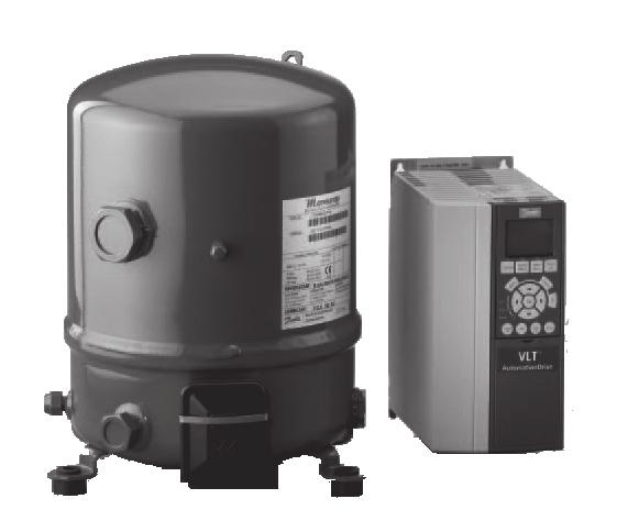
5 Contents 1 - Introduction 2 - Transportation, storage 3 - Safety measures prior to assembly 4 - Assembly 5 - Leak detection 6 - Vacuum dehydration procedure 7 - Electrical connections 8 - Filling the system 9 - Verification before commissioning 10 - Start up 11 - Troublesooting 12 - Maintenance 13 - Replacement 14 - User advisory 1 - Introduction These Instructions pertain to Maneurop Variable Speed hermetic compressors used for A/C and refrigeration purposes. They are intended to provide necessary information regarding safety features and proper handling of this product. Note that this is a general document for the entire range of Variable Speed hermetic compressors; certain details therefore may not be applicable to the particular model you have purchased. Please keep your manual and all relevant information handy for future reference. Equipment description: This compressor is delivered with all assembly equipment (rubber grommets + screws + washers), an electrical box (cover + spring), connecting sleeves and gaskets, and Instructions. Approved list of refrigerants: - The VTZ series can be used with R404A, R507A, R407C and R134a. Compressors are filled with lubricant before leaving the factory: - The VTZ series with Polyolester oil (ref. 160PZ), This lubricant must not be mixed with one another. Maneurop Variable Speed compressors must only be used for their designed purpose(s) and within their scope of application (Please refer to the Application Guidelines). Maneurop compressors are delivered under nitrogen gas pressure (between 1 and 2 bar) and hence cannot be connected as is; please refer to the Assembly section for further details. Compressors are not certified for mobile and explosion-proof applications. Any use of flammable refrigerant (e.g. hydrocarbons) or air is also strictly forbidden. Under all circumstances, the EN378 (or other local regulation) requirement must be fulfilled. When pressure tests are required on the system, they are to be performed by qualified personnel, in paying close attention to potential pressure-related hazards and heeding the pressure limits displayed on the compressor nameplate or in the application guidelines. Modifications or alterations to the compressor (such as brazing on the shell) not expressly approved by the party responsible for ensuring compliance could invalidate the user s authorization to operate the equipment. 2 - Transportation, storage The compressor must be handled in the vertical position (maximum offset from the vertical: 15 ).Should the compressor be handled in an upside-down position, its performance may no longer be insured. Beware that all compressor handling must be carried out with extreme caution to avoid any shocks. Dedicated packing handles are to be used for all required manipulation of the compressor; otherwise appropriate and safe lifting equipment is to be used during handling and unpacking. Any damage noticed on either the packaging or the product itself upon reception should be indicated on a Customer Claim addressed to the shipping company. The same recommendation applies to all instances when transport instructions have not been fully respected. Please review the safety instructions printed on the cardboard packaging before storage. Verify that the compressor is never stored in an ambient temperature of below -35 C (-31 F) or above 50 C (122 F). Ensure that the compressor and its packaging are not exposed to rain and/or a corrosive, flammable atmosphere. 3 - Safety measures prior to assembly All installation and servicing is to be performed by qualified personnel in compliance with all pertinent practices and safety procedures. The compressor must be located in a ventilated area to ensure that the ambient temperature never exceeds 50 C (122 F) during the off-cycle. Make certain that the compressor can be mounted onto a horizontal plane with a maximum slope of 3. The compressor can only be supplied by a frequency converter. Make sure that the drive is the dedicated one for the compressor (power size and voltage: input & ). Compressor/ frequency converter/refrigerant models selection are listed on parameter 1.13 of the frequency converter. Ensure that refrigerant-charging equipment, vacuum pumps, etc. for HFC refrigerant systems have been specifically reserved for these refrigerants and never used with other CFC, HCFC refrigerants. Use only clean and dehydrated refrigeration-grade copper tubes as well as silver alloy brazing material. Verify that all system components are appropriate (use of refrigerant, etc.), clean and dehydrated before being connected to the completed assembly. Perform a check on the suction lines: Horizontal sections are to be sloped downwards towards the compressor. Suction gas velocity must be high enough to provide for an adequate oil return. This velocity must be within 8 to 12 m/s in vertical risers. In horizontal pipes, this velocity can decrease to 4 m/s. The use of U-trap and double-suction risers may be required on vertical sections, but not in excess of 4 m unless a second U-trap system has been fitted (refer to Figs. 2, 3 and 5). Suction line piping must be insulated in order to minimize the effects of superheating. Perform a check on the discharge lines: Piping to the condenser must be designed so as to prevent liquid return to the compressor and adequat refrigerant gas velocity. The use of non-return valves may prove necessary, depending on the position of the compressor with respect to the condenser. A suitably-sized U-trap may also be necessary if the condenser has been placed above the compressor (refer to Fig. 1). The piping connected to the compressor must be configured on the basis of a flexible 3-axis design to dampen vibrations and designed in such a way as to prevent free liquid refrigerant migration and drainage back to the compressor sump and discharge cylinder heads (refer to fig. 1). Make sure the installation is equipped with highpressure safety components (e.g. pressure switch, pressure relief valve) to prevent against the bursting of pressure-containing components. Note that all local and regional regulations and safety standards, such as EN 378, must be taken into account when designing, connecting and running the system 4 - Assembly The compressor s time of exposure to the atmosphere during installation shall be held to a minimum (less than 1/2 hour). The compressor connection must be fast in order to avoid moisture contamination of the lubricant. The grommets must be installed under the compressor feet, as shown in Fig. 4. Rubber grommets are to undergo compression until contact is made between the flat washer and the steel mounting sleeve. Before opening the compressor connection fittings, it is mandatory to connect a service hose to the Schrader fitting on the compressor shell in order to gradually release the nitrogen holding charge. Ensure that no material enters into the system while cutting the tubing. Moreover, never drill holes in the pipe work after installation. Should additional components need to be connected onto the compressor sight glass or oil equalization ports, it is recommended that such an operation be carried out prior to final assembly, to allow for compressor inclination and movement. Avoid flare-type connections and exercise great care while brazing (use only state-of-the-art practices); apply a nitrogen gas flow to prevent oxidation inside the tubing. All brazing material is to contain a minimum of 5% silver. If flux additive is used, don t put the copper tube into the receiver of flux, but put flux around the tube (i.e. with a pencil). this will prevent pure flux getting inside the tube. When brazing, protect the terminal box and painted surfaces of the compressor from torch heat damage. Remove the Teflon gaskets when brazing Rotolock connectors with the solder sleeve and be aware that original suction and discharge gaskets must be replaced. When installing Rotolock fittings, always use two wrenches when tightening any fittings to insure that the torque is effectively cancelled on the adjacent tubing and fittings. Do not exceed the maximum tightening torque for Rotolock connections to the compressor : 1" rotolock 80 Nm 1"1/4 rotolock 90 Nm 1"3/4 rotolock 110 Nm. Be sure to connect the required safety and control devices onto compressor shut-off valves or fittings. In case of oil return through the Schrader fitting on the compressor shell, make sure the internal valve is removed. 5 Leak detection Never use oxygen or dry air in order to avoid the risk of fire or explosion. Perform a leak detection test on the complete system by means of: a dry nitrogen pressure test, a mixture of nitrogen and the refrigerant to be used in the system, a helium leak test and/or a
6 deep vacuum test. The test should be long enough in duration to ensure the absence of any slow leaks in the system. Use tools specifically designed for detecting leaks. The low side test pressure must not exceed 1.1 x Ps pressure indicated on the compressor nameplate. For high side test pressure recommendations, please refer to the Application Guidelines. Whenever the compressor is equipped with suction and discharge shut-off valves, these valves are to remain in the closed position while performing the leak test (compressor leak test already performed in the factory). Should a leak be discovered, proceed with repair steps and repeat the leak detection. When a deep vacuum leak detection test is selected, observe the following: 1) The level to reach is 500 µm Hg. 2) Wait 30 min. 3) If pressure increases rapidly, the system is not airtight. Locate and repair leaks. Restart the vacuum procedure, followed by steps 1, 2, etc. 4) If pressure increases slowly, the system contains moisture inside. Break the vacuum with nitrogen gas and restart the vacuum procedure, followed by steps 1, 2, etc. 5) Connect the compressor to the system by opening the valves. 6) Repeat the vacuum procedure, followed by steps 1, 2, etc. 7) Break the vacuum with nitrogen gas. 8) Repeat the vacuum procedure, steps 1, 2; a vacuum of 500 µm Hg (0.67 mbar) should be reached and maintained for 4 hours. This pressure is to be measured in the refrigeration system, and not at the vacuum pump gauge. Do not use a megohmeter or apply power to the compressor while it is under vacuum, as this may cause motor winding damage (motor burn-out). Do not use colored leak detection fluids. 6 - Vacuum procedure Whenever possible (if shut-off valves are present), the compressor must be isolated from the system. It is essential to connect the vacuum pump to both the LP & HP sides, in order to avoid deadending system parts. Recommended procedure: 1) Once leak detection has been completed, 2) Pull down the system under a vacuum of 500 µm Hg (0.67 mbar). 3) When the vacuum level of 500 µm Hg has been reached, the system must be isolated from the pump. 4) A vacuum of 500 µm Hg (0.67 mbar) has to be reached and maintained for 4 hours. This pressure is to be measured in the refrigeration system, and not at the vacuum pump gauge. If pressure increases, restart the leak-detection procedure (refer to the Leak detection section of this manual if necessary). Vacuum pump: A two-stage vacuum pump with gas ballast (1.5- mbar standing vacuum) shall be used; its capacity is to be consistent with system volume. Never use the compressor as a vacuum pump. It is recommended to use large-diameter connection lines and to connect these lines to the shut-off valves, rather than to the Schrader connection. This recommendation allows avoiding excessive pressure losses. Moisture level: At the time of commissioning, system moisture content may be as high as 100 ppm. During operation, the liquid line filter dryer must reduce this level to < 20 ppm. Additional notes: To improve moisture removal, the temperature of the system should not be lower than 10 C. If the evaporator coil is equipped with electrical defrost heaters, these heaters should be energized. A proper vacuum procedure is even more important with HFC and polyolester lubricant than it has traditionally been with HCFC (R22) or CFC and mineral oil. For further details, please refer to TI Do not use a megohmeter or apply power to the compressor while it is under vacuum, as this may cause motor winding damage (motor burn-out). 7 - Electrical connections Make sure the main power supply to the system has been switched off and isolated, in accordance with applicable regulations, before performing any electrical connection. Please refer to Fig 7, 8 and 9 for typical wiring connections and examine the specific wiring diagram located in the frequency converter package. For further details, refer to the application guidelines. Follow very closely the installation instruction for frequency converter: - See principal for mounting (fig 6): base frame of the frequency converter needs to very well fixed to the support to ensure a very good continuity between the earth potential of every electrical panel and boxes of the system. - See principal for wiring (fig 7, 8 and 9): bases are that all control wires have to be of a screeened design, the cable for electrical motor supply has to be of a shielded design too. Correct earthing of the shield cover has to be done using the method shown on fig 8 and 9, every time this one has to be earthed on each end of the cables. Distinct cable tray must be used for control and motor supply. The frequency converter ensures direct motor protection and the factory set parameters are designed such as it is protecting the motor over all current malfunctions. So an external over-load is not necessary. Set the frequency converter parameters in accordance with Danfoss recommendations for the couple of CD 302 frequency converter and VTZ variable speed compressor. Maneurop compressors are able to operate in both directions (rotation). Depending on motor size, the power supply connection utilizes either a spade connector (1/4 - AMP-AWE) or a T-block connector (screw type UNF x 9.5). For screw-type connections, be aware that the maximum tightening torque is 3 Nm. A 5-mm earth terminal screw is provided in the compressor junction box for the grounding connection. All electrical components must be selected as per local standards and compressor requirements. 8 - Filling the system Before charging the refrigerant, verify that the oil level is between ¼ and ¾ on the compressor oil sight glass (when mounted) and/or ensure that the oil charge of the original compressor is sufficient as regards system dimension and piping design: - An additional quantity of oil might be necessary for line lengths (back and forth) in excess of 20 m. - An additional quantity of oil might be necessary to compensate the quantity trapped in the oil separator and oil reservoir when used. - In the event additional oil is required, use only an approved lubricant (refer to the Introduction section of this manual). - Use the compressor oil sight glass or the sight glass from the oil level controller when used to check the proper oil level when commissioning after stabilization of the complete refrigeration system. For all information necessary on adding oil to the compressor, refer to TI Make sure the refrigerant used to fill the system is compatible with compressor design. Refer to the Introduction section of this manual for an approved list of refrigerants Compressor switched off: The liquid refrigerant is charged into the condenser and/or liquid receiver in the liquid phase (compulsory for refrigerant blends). The charge must be as close to the nominal system charge as possible in order to avoid both low pressure operations and excessive superheating at start-up. Throughout this operation, both compressor service valves must remain closed. Remember that vapor-charging is only appropriate for pure refrigerants. To the extent possible, maintain the refrigerant charge below 2.5 kg per cylinder. Above this limit, install a system, such as a pump-down cycle or suction line accumulator, to prevent against liquid flood-back into the compressor. Be sure that the refrigerant charge is suitable for both winter and summer operations 9 - Verification before commissioning Ensure that all service valves are in the open position before start-up. A closed discharge or suction service valve may cause serious damage to the compressor and/or compromise safety device operation, thereby resulting in potential injury to personnel. Check that all safety devices are operational and properly set (safety pressure switch set point, mechanical relief valve if necessary, etc.). Make sure that these devices comply with both generally- and locally-applicable regulations and standards (e.g. EN 378). When using high-pressure switches or relief valves, the setting must not exceed maximum service pressure of any system component. Refer to the Application Guidelines for relevant compressor pressure safety limits. A low-pressure switch is recommended to prevent operation under vacuum. Use a minimum setting of 1.1 bar (absolute). Verify that all electrical connections are properly fastened and in compliance with local safety regulations. When a crankcase heater is required (refer to the Application Guidelines), ensure that it has been energized for a minimum of 12 hours before initial start-up and/or during prolonged shutdown periods Start up Never start the compressor in the absence of a refrigerant charge. Do not bypass the LP or any other safety switches during start-up. Check current draw and voltage levels on the
7 main. The values for the compressor electrical motor can be directly displayed on the frequency converter control panel. Monitor the oil sight glass for 60 min. after system equilibrium to ensure proper oil return to the compressor. This oil check has to be done over the speed range to garanty: - a good oil return at low speed when gas velocity is at it s minimum, - a good oil management at high speed where oil carry over is at it s maximum. Suction superheat setting: Optimal compressor suction superheat would be around 10K, with the maximum allowable superheat being 30K. In all cases, the application limits of the compressor must be respected; moreover, high superheat values lead to high discharge temperatures and decrease compressor capacity. The maximum discharge temperature is 130 C: operating at a higher temperature may result in refrigerant decomposition. Under steady-state operating conditions, check refrigerant piping or capillary tubes for abnormal vibrations (refrigeration line movement in excess of 1.5 mm necessitates corrective actions, pipe brackets, etc.). After 2 to 4 hours of operations under established conditions, check the oil level and add oil if necessary (refer to TI 2-025). If oil return continues to perform poorly, further investigation of the piping design is required. Ensure that refrigerant flow through the liquid line sight glass (when mounted) is adequate and that operating temperatures correspond with system specifications. When needed, refrigerant may be added in the liquid phase, carefully throttling the refrigerant on the low-pressure side and as far as possible from the compressor. The compressor must be operating during this process at a medium speed if possible (this can be manually hand forced at 50 Hz for exemple). Do not overcharge the system. 11 Troubleshooting Compressor failure to start: Verify that the compressor is hooked up to the frequency converter; check the power lead connections. If these verifications reveal no abnormality, control the motor windings with an ohmmeter. Check the frequency converter control panel: If any alarm is displayed check the wiring and specially the polarity of the control cables, when an alarm is shown refer to the converter application manual and specially revue the electrical motor parameters set in. Compressor failure to build up pressure: Check to make sure that all bypass valves in the system have not been opened. Also check that all solenoid valves are in their proper position. Abnormal running noise: Ensure the absence of any liquid flood-back to the compressor by means of measuring the return gas superheat and compressor sump temperature. The sump should be at least 10K above the saturated suction temperature under steady-state operating conditions. The high-pressure switch trips out: Check condenser operations (condenser cleanliness, fan operations, water flow and water pressure valve, water filter, etc.). If above check out OK, the problem may be due to either refrigerant overcharging or the presence of a noncondensable (e.g. air, moisture) in the circuit. The low-pressure switch trips out: Check evaporator operations (coil cleanliness, fan operations, water flow, water filter, etc.), liquid refrigerant flow and pressure drops (solenoid valve, filter dryer, expansion valve, etc.), refrigerant charge. Low refrigerant charge: The correct refrigerant charge is given by the liquid sight glass indication, the condenser delta T in relation to the refrigerant pressure tables (pressure-temperature), the superheat and the sub-cooling, etc. (if additional charge is deemed necessary, refer to the Filling the system section). Compressor short cycling: The number of cycles shall never exceed 12 starts per hour Maintenance Maneurop compressors do not necessitate any special maintenance procedure. However, it must be recalled that proper operations and maintenance of the system serve to prevent against system-related compressor problems. The following preventive maintenance checks, to be performed at regular intervals, are highly recommended: - Control operating conditions (evaporating temperature, condensing temperature, compressor discharge temperature, temperature difference on heat exchangers, superheat, sub-cooling). These conditions must always remain within compressor operation limits. - Verify that safety devices are operational and properly set. - Check the compressor oil level and quality; this step may include an acid test, humidity check, spectrometer analysis, etc. whenever the oil becomes discolored. - Ensure that the circuit is leak tight. - Verify the proper operation of heat exchangers and, if necessary, clean them. - Check the current draw on the compressor motor as well as proper voltage balance between phases. - Check that all electrical connections are still adequately fastened. - Make sure the compressor is clean and in good working order; verify the absence of rust on the compressor shell, piping and electrical connections. - Make sure the refrigerant charge is suitable for both winter and summer operations. Insure that periodic in-service inspections required by local regulations are performed. For the frequency converter check the internal temperature on the display and control the proper air flow for cooling. Fault are logged on the converter memory and can be displayed, this can help to revue some parameter of the frequency converter or of the system itself. 13 Replacement Precaution must be taken when disconnecting, cutting or drilling holes in the tubing to ensure that no refrigerant under pressure is present in the system. The refrigerant shall not be discharged directly into the atmosphere; rather, it must be removed using approved reclamation techniques and equipment and then safely stored, in accordance with applicable legislation. The presence of refrigerant vapor can displace air and lead to suffocation. Proper ventilation is mandatory at all times when servicing the equipment. A refrigeration system component change must be carried out in compliance with local regulations. Make sure that the main power supply has been switched off. Before replacement, it is necessary to determine the cause of failure and implement remedial action. If such analysis and repair are not performed, repetitive failure may occur. Note that an oil acidity test always proves helpful in diagnosis when undertaking compressor replacement. Don t forget to use the fault memory of the frequency converter and to recover the fault descriptions before initializing the system and even shutting off the power Check that the new Maneurop compressor and the on-site compressor to be replaced display the same electrical and refrigeration performance characteristics. Use the rubber grommets and gaskets supplied with the new compressor. Whenever piping needs to be modified, please refer to the Safety measures prior to assembly section. For further details on replacement steps, refer to the previous sections of this manual. Danfoss recommends not to throw away a used compressor but to dispose of the compressor and its oil at a specialised recycling company site. Note: In the event of motor failure, flush and clean the entire circuit before replacing the compressor in order to remove acids and contaminants. Systematically install a new filter dryer on the liquid line. Prior to this step (if necessary), run the system for at least 2 hours with anti-acid cartridges (in such instances, the installation of a suction filter might also be required). After an operating period of approximately 2 weeks, check the level of oil acidity. If the oil acid test proves positive, drain and replace the oil, replace the anti-acid liquid line filter dryer cartridges and the suction filter previously installed. Repeat oil and filter dryer replacements until the system is clean and acid-free. When there is no longer any sign of acidity, replace the anti-acid cartridges by the standard model and remove the suction strainer cartridge as required User advisory Insist that all service operations only be performed by qualified personnel. The compressor and tubing surface temperatures may exceed 100 C (212 F) and cause severe bodily burns. Special precaution must be taken when working around the compressor and refrigerant tubing. Moreover, a compressor in operation can generate very cold surface temperatures (as low as -45 C / - 49 F), thereby exposing personnel to the risk of freezing burns. Pressure inside the compressor can reach dangerously high levels (e.g. abnormal operation, fire, ) leading to personnel injury if suddenly released; therefore, never drill, weld or cut the compressor shell and adjacent tubing (release of liquid refrigerant can cause flash freezing on exposed skin). Be aware that the product warranty may be deemed null and void in the following cases: external modifications to the compressor (absence of nameplate, drilling, welding, broken feet, shock marks), compressor opened by the customer or returned unsealed (i.e. open discharge or suction ports), presence of rust or water inside the compressor, addition of leak-detection fluid in the lubricant,
8 use of a refrigerant or lubricant not approved by Danfoss Commercial Compressors, any deviation from recommended instructions pertaining to installation, application or maintenance, use in mobile applications (boats, trains, trucks, etc.) or under explosive atmospheric conditions (the compressor connecting box is not explosion-proof). The date of production of the compressor is indicated on the nameplate. Ensure that the model and serial number information are always transmitted with any claim filed regarding this product. Danfoss Commercial Compressors Danfoss can accept no responsibility for possible errors in catalogues, brochures and other printed material. Danfoss reserves the right to alter its products without notice. This also applies to products already on order provided that such alterations can be made without subsequential changes being necessary in specifications already agreed. All trademarks in this material are property of the respective companies. Speerall, Danfoss and the Danfoss logotype are trademarks of Danfoss A/S. All rights reserved P01-A
Installation and maintenance condensing unit manual
 Installation and maintenance condensing unit manual OP-HJZM / HNUM / HRUM / LJZM / LNZM / LRZM http://cc.danfoss.com Installation & Maintenance Label R404A A: Model and bar code B: Unit code and bar code
Instructions OP-LPHM & OP-MPHM OP-LPHM & OP-MPHM & OP-MPUM & OP-MPGM034
 OP-PH018-026 & OP-PH007-010-012-015-018 OP-PH048-068 & OP-PH026-034 & OP-P034-046 & OP-PG034 1 FRCC.EI.019.A2. Danfoss Commercial Compressors 06/12 OP-PH096-136 & OP-P068-080-107 OP-PH215-271 & OP-P125-162
KITS COMMON TO HEATING AND COOLING EQUIPMENT 504,652M 03/04. Supersedes 503,249M
 2004 Lennox Industries Inc. Dallas, Texas KITS COMMON TO HEATING AND COOLING EQUIPMENT 504,652M 03/04 Supersedes 503,249M Litho U.S.A. COMPRESSOR REPLACEMENT KIT INSTALLATION INSTRUCTIONS FOR COMPRESSOR
General Characteristics SM185S3QC. Dimensions. Terminal box. Electrical Characteristics. Recommended Installation torques
 Datasheet, technical data Performer scroll compressor, SM185-3 General Characteristics Model number (on compressor nameplate) Code number for Singlepack* Code number for Industrial pack** Drawing number
CS/CD/CP AIR COOLED CONDENSING UNITS (P/N E207120C R2)
") CS*/CD*/CP* Series Air Cooled Condensing Units Operating and Installation Manual CS/CD/CP AIR COOLED CONDENSING UNITS (P/N E207120C R2) TABLE OF CONTENTS I. Receipt of Equipment 2 II. Piping...4 III. System
CS*/CD*/CP* Series Air Cooled Condensing Units Operating and Installation Manual CS/CD/CP AIR COOLED CONDENSING UNITS (P/N E207120C R2) TABLE OF CONTENTS I. Receipt of Equipment 2 II. Piping...4 III. System
Contour TM Screw Compressors
 Contour TM Screw Compressors Semi-Hermetic Compact Operating Instruction SCH1 High Temp Compressors Form No. 99-77 1. Introduction This series of semi-hermetic compact screw compressors is designed for
Condensing Unit Installation and Operating Instructions
 Bulletin WCU_O&I 01 June 2003 Condensing Unit Installation and Operating Instructions WCU Air Cooled Condensing Unit Table of Contents Section 1. Section 2. Section 3. Section 4. Section 5. Section 6.
This chapter is devided into two sections:
 This chapter is devided into two sections: Page Installation requirements........................................................................ 127 The installation process..........................................................................
NON-CYCLING REFRIGERATED AIR/GAS DRYERS QPNC 75 to QPNC 250 OPERATOR S MANUAL
 NON-CYCLING REFRIGERATED AIR/GAS DRYERS QPNC 75 to QPNC 250 OPERATOR S MANUAL DATE OF PURCHASE: MODEL: SERIAL NO.: Record above information from nameplate. Retain this information for future reference.
DLCLRA. INSTALLATION INSTRUCTIONS Outdoor Unit Single Zone Ductless System Sizes 36 to 58 TABLE OF CONTENTS
 DLCLRA INSTALLATION INSTRUCTIONS Outdoor Unit Single Zone Ductless System Sizes 36 to 58 Fig. 1 - Size 36 TABLE OF CONTENTS PAGE SAFETY CONSIDERATIONS... 2 PARTS LIST... 3 SYSTEM REQUIREMENTS... 4 WIRING...
Inverter scroll compressors VZH hybrid manifold
 Application guidelines Inverter scroll compressors VZH hybrid manifold R410A http://cc.danfoss.com Contents...4 Scope...4 Benefits...4...5 Oil management concept...5 System configuration...5 Dimensions...8
Danfoss scroll compressors SH - In parallel installation
 Application guidelines Danfoss scroll compressors SH - In parallel installation 50 Hz - 60 Hz - R410A http://cc.danfoss.com Contents General overview... 5 Benefits... 5 Scope... 5 Design challenge...
Maneurop reciprocating compressors NTZ
 Maneurop reciprocating compressors NTZ R404A - R507-60 Hz http://danfoss.us.com/ Content Maneurop reciprocating compressors...5 Features...5 Specifications...6 Technical specifications and nominal ratings...6
Danfoss Inverter scroll compressor, VRJ
 Application Guidelines Danfoss Inverter scroll compressor, VRJ For Residential Applications - R410A http://danfoss.us.com/ Contents Introduction...6 Scroll compressor components... 6 Compressor size...
Inverter scroll compressors VZH hybrid manifold
 Application guidelines Inverter scroll compressors VZH hybrid manifold R410A http://cc.danfoss.com Contents...4 Scope...4 Benefits...4...5 Oil management concept...5 System configuration...5 Dimensions...8
Danfoss scroll compressors SH- In parallel installation
 MAKING MODERN LIVING POSSIBLE Application guidelines Danfoss scroll compressors SH- In parallel installation 50 Hz - 60 Hz - R410A www.danfoss.com CONTENTS General overview...4 Benefits... 4 Scope...
14. The center port of the manifold is used for evacuation, charging and refrigerant recovery.
 HET- 190 ESL Support page 1 CORE Basic Refrigeration Circuit 1. Liquid refrigerant boils in the evaporator. Heat is absorbed. The heat energy absorbed converts refrigerant liquid into vapor. 2. Refrigerant
Installation Instructions
 38MHR Outdoor Unit Single Zone Ductless System Sizes 09 to 24 Installation Instructions NOTE: Read the entire instruction manual before starting the installation. NOTE: Images are for illustration purposes
Maneurop reciprocating compressors
 MAKING MODERN LIVING POSSIBLE Maneurop reciprocating compressors NTZ R404A - R507A SELECTION & APPLICATION GUIDELINES CONTENTS MANEUROP RECIPROCATING COMPRESSORS... 4 Features... 4 Compressor reference...
Retrofit and High Glide Refrigerants
 Technical paper Retrofit and High Glide Refrigerants Danfoss statement By Norbert Blatz, Global Application Excellence Manager, John Broughton, Global Application Expert, Commercial Refrigeration, Rasmus
Service Step by Step Trouble-Shooting Check-List
 WARNING: Only Data Aire trained technician or experience technicians should be working on Data Aire Equipment. Protect yourself at all times and work safe. Date: Dates at the job site: From: to Job#: Serial#:
PARALLEL RACK SYSTEM INSTALLATION & OPERATIONS MANUAL With Master Rack Compressor Sequencer
 PARALLEL RACK SYSTEM INSTALLATION & OPERATIONS MANUAL With Master Rack Compressor Sequencer 5/16 Rev. A 57-02509 2 Contents INTRODUCTION... 4 WARNING LABELS AND SAFETY INSTRUCTIONS... 5 PS SERIES PARALLEL
A: RS-45 is a non ozone depleting Drop-in replacement for R22 in most applications. A: RS-45 is a blend of R143a, R125, R134a and isobutane.
 1/1/12 RS-45 (R434A): Q & A 1 Q: What is RS-44? 1.Q: What is RS-45 A: RS-45 is a non ozone depleting Drop-in replacement for R22 in most applications. 2 Q: Yes, but what does RS-45 contain? A: RS-45 is
LIQUID REFRIGERANT CONTROL IN REFRIGERATION AND AIR CONDITIONING SYSTEMS
 22-1182 Application Engineering Bulletin AE-1182-R24 Revised April 1, 1993 LIQUID REFRIGERANT CONTROL IN REFRIGERATION AND AIR CONDITIONING SYSTEMS One of the major causes of compressor failure is damage
Condensing Unit Installation and Operating Instructions
 Bulletin ACU_O&I 02 August 2016 Condensing Unit Installation and Operating Instructions ACU Air Cooled Condensers Table of Contents Section 1. General Information... 2 Section 2. Refrigeration Piping...
Performer Heat Pump scroll compressors 50 Hz - R407C Selection & application guidelines
 MAKING MODERN LIVING POSSIBLE Performer Heat Pump scroll compressors 50 Hz - R407C Selection & application guidelines CONTENTS SCROLL COMPRESSION PRINCIPLE... 3 Scroll compressor components... 3 The
TABLE OF CONTENTS. NOTE: Read the entire instruction manual before starting the installation. TROUBLESHOOTING... 13
 R 410A Duct Free Split System Air Conditioner and Heat Pump Product Family: DFS4(A/H) System, DFC4(A/H)3 Outdoor, DFF4(A/H)H Indoor NOTE: Read the entire instruction manual before starting the installation.
Maneurop reciprocating compressors
 MAKING MODERN LIVING POSSIBLE Maneurop reciprocating compressors MT/MTZ 50-60 Hz R22 - R407C - R134a - R404A / R507A SELECTION & APPLICATION GUIDELINES CONTENTS MANEUROP RECIPROCATING COMPRESSORS... p
INSTALLATION, COMMISSIONING AND OPERATING MANUAL
 INSTALLATION, COMMISSIONING AND OPERATING MANUAL 1 YTBV-D-CE42_0109 CONTENT Available models and capacities Supplier information Warranty Safety Emergency stops/ shutdowns About this manual Models Physical
Operation and Maintenance Manual
 Warranty Information Ritchie Engineering guarantees YELLOW JACKET products to be free of defective material and workmanship which could affect the life of the product when used for the purpose for which
RecoverX Oil-Filled Hermetic Refrigerant Recovery System. Operation and Maintenance Manual
 RecoverX Oil-Filled Hermetic Refrigerant Recovery System Operation and Maintenance Manual Table of Contents Page General Safety Instructions 2-3 System Overview 3 Operating Guide 4 Restart Procedure 4
Installation Instructions
 40MBFQ Floor Console Ductless System Sizes 09 to 12 Installation Instructions TABLE OF CONTENTS PAGE SAFETY CONSIDERATIONS... 2 PARTS LIST... 3 SYSTEM REQUIREMENTS... 4 DIMENSIONS... 5 CLEARANCES... 5
APPLICATION GUIDELINES FOR COPELAND COMPLIANT SCROLL COMPRESSORS (ZR*1 Models)
") 4-1280 Application Engineering Bulletin AE-1280R4 Revised April, 1995 APPLICATION GUIDELINES FOR COPELAND COMPLIANT SCROLL COMPRESSORS (ZR*1 Models) Introduction The Compliant Scroll Compressor has been
4-1280 Application Engineering Bulletin AE-1280R4 Revised April, 1995 APPLICATION GUIDELINES FOR COPELAND COMPLIANT SCROLL COMPRESSORS (ZR*1 Models) Introduction The Compliant Scroll Compressor has been
Installation Instructions
 40MAQ High Wall Ductless Split System Sizes 09 to 36 Installation Instructions NOTE: Read the entire instruction manual before starting the installation TABLE OF CONTENTS PAGE SAFETY CONSIDERATIONS 2 PARTS
Refrigerant Recovery Unit, Model RRU134
 Installation, Operation & Maintenance Manual IOMM RRU134 Group: Refrigerant Effective: December 2000 Supersedes: New Refrigerant Recovery Unit, Model RRU134 1999 McQuay International Table of Contents
INSTALLATION, OPERATING & MAINTENANCE INSTRUCTIONS FOR 350 SERIES CIRCULATION HEATERS
 INDEECO Circulation Heaters are designed to provide years of trouble free operation if properly installed and maintained. Please read and follow these instructions for installing and maintaining the heater.
38GHP AIR-COOLED MULTI SPLIT CONDENSING UNITS
 Concepcion Carrier Air conditioning Company Philippines INSTALLATION MANUAL, START-UP & SERVICE INSTRUCTIONS 38GHP AIR-COOLED MULTI SPLIT CONDENSING UNITS CONTENTS: Physical Data and Dimensions........
Maneurop reciprocating compressors. MT/MTZ Hz - R22 - R407C - R134a - R404A / R507A MAKING MODERN LIVING POSSIBLE
 MAKING MODERN LIVING POSSIBLE Maneurop reciprocating compressors MT/MTZ 50-60 Hz - R22 - R407C - R134a - R404A / R507A REFRIGERATION & AIR CONDITIONING DIVISION Selection & Application guidelines Contents
Installation Instructions
 24AHA4 Performance Series Air Conditioner with Puron Refrigerant 1-1/2 to 5 Nominal Tons Installation Instructions Fig. 1-24AHA4 A07532 SAFETY CONSIDERATIONS Improper installation, adjustment, alteration,
DLCSRA. INSTALLATION INSTRUCTIONS Outdoor Unit Ductless Split System Sizes 09 to 36 TABLE OF CONTENTS
 DLCSRA INSTALLATION INSTRUCTIONS Outdoor Unit Ductless Split System Sizes 09 to 36 NOTES: Read the entire instruction manual before starting the installation. Images are for illustration purposes only.
Maneurop reciprocating compressors NTZ
 Application guidelines Maneurop reciprocating compressors NTZ R404A - R507 - R452A http://cc.danfoss.com Content Maneurop reciprocating compressors... 5 Features...5 Specifications... 6 Technical specifications
Installation Instructions
 38MPRA Outdoor Unit Single Zone Ductless System Sizes 09 to 12 Installation Instructions NOTES: Read the entire instruction manual before starting the installation. Images are for illustration purposes
REFRIGERANT CHANGEOVER
 Date of last update: Dec-17 Ref: CC7.26.5/0117-1217/E Application Engineering Europe REFRIGERANT CHANGEOVER FROM HFC R134a TO HFC/HFO R450A & R513A WARNING Use only Emerson approved refrigerants and lubricants
INSTALLATION AND MAINTENANCE INSTRUCTIONS 4SCU16LT Series Split System Air Conditioner WARNING
 INSTALLATION AND MAINTENANCE INSTRUCTIONS 4SCU16LT Series Split System Air Conditioner WARNING The equipment covered in this manual is to be installed by trained and experienced service and installation
Installation Instructions
 40MBFQ Floor Console Ductless System Sizes 09 to 58 Installation Instructions TABLE OF CONTENTS PAGE SAFETY CONSIDERATIONS... 2 PARTS LIST... 3 SYSTEM REQUIREMENTS... 4 WIRING... 4 DIMENSIONS... 5 CLEARANCES...
Danfoss scroll for refrigeration LLZ013 to low temperature
 MAKING MODERN LIVING POSSIBLE Application guidelines Danfoss scroll for refrigeration LLZ013 to 033 - low temperature 50-60 Hz - R404A - R507 http://cc.danfoss.com Contents Features...4 Scroll compression
12 In Row. Installation Manual. MISSION CRITICAL Air Conditioning Systems. ClimateWorx International Inc.
 MISSION CRITICAL Air Conditioning Systems 12 In Row Installation Manual ClimateWorx International Inc. 14 Chelsea Lane, Brampton, Ontario, Canada L6T 3Y4 2 Table of Contents Table of Contents... 3 Site
INSTALLATION INSTRUCTIONS TXV Horizontal Slab Coils WLSH
 TXV Horizontal Slab Coils WLSH These instructions must be read and understood completely before attempting installation. It is important that the Blower and Duct System be properly sized to allow the system
RESEARCH AND TECHNOLOGY BUILDING RENOVATION 05/18/09 SECTION REFRIGERANT PIPING AND SPECIALITIES
 SECTION 23 23 00 REFRIGERANT PIPING AND SPECIALITIES PART 1 - GENERAL 1.1 SUMMARY A. Section Includes: 1. Refrigerant piping. 2. Unions, flanges, and couplings. 3. Pipe hangers and supports. 4. Refrigerant
Operating instructions for semi-hermetic motorcompressors
 Operating instructions Page 1 Operating instructions Type: HG 4/310-8/4 S HG 4/385-8/4 S HG 4/465-8/4 S HG 4/555-8/4 Page 2 Page 3 Contents Page 1. Safety instructions...4 2. Main and functional parts...4
Danfoss scroll compressors CXH140 - single and manifold installation
 Application guidelines Danfoss scroll compressors CXH140 - single and manifold installation 50Hz - R410A http://cc.danfoss.com Content CXH single compressors... 4 CXH manifold installation... 41 FRCC.PC.030.A3.02
DANFOSS OPTYMA PLUS INVERTER UNITS
 Optyma Plus Inverter Condensing Units Danfoss Optyma Plus Inverter Units are designed with the unique benefits of stepless inverter scroll technology resulting in a 20-30% higher energy efficiency in a
a. CFCs. b. HCFCs. c. Pressurized nitrogen. d. Compressed dry air. 17. The state of the refrigerant leaving the condenser of a refrigeration system
 Core 1. Ozone in the stratosphere above the earth consists of: a. Molecules containing 3 oxygen atoms. b. Molecules of 2 oxygen atoms. c. Radioactive particles. d. Pollutants that have risen from ground
Danfoss scroll compressors In parallel installation SM/SY/SZ
 Application guidelines Danfoss scroll compressors In parallel installation SM/SY/SZ http://cc.danfoss.com Content Compressor model designation... 4 Nomenclature...4 General overview... 5 Benefits...5
NO. 15FD-742 ISSUED: AUG. 10, 2007 REVISED: SEP. 30, 2013 HOSHIZAKI SELF-CONTAINED CRESCENT CUBER KM-30A KM-35A KM-50A KM-75A MODEL SERVICE MANUAL
 NO. 15FD-742 ISSUED: AUG. 10, 2007 REVISED: SEP. 30, 2013 HOSHIZAKI SELF-CONTAINED CRESCENT CUBER MODEL KM-30A KM-35A KM-50A KM-75A SERVICE MANUAL CONTENTS PAGE I. SPECIFICATIONS--------------------------------------------------------------------------------------1
Some of these procedures need to be performed to conform to requirements of the Clean Air Act.
 Leak Detection, Recovery, Evacuation and Charging Four basic service procedures used to repair and maintain a mechanical refrigeration system are leak detection, evacuation, recovery, and refrigerant charging.
Maneurop reciprocating compressors MT / MTZ
 MAKING MODERN LIVING POSSIBLE Application guidelines Maneurop reciprocating compressors MT / MTZ 50-60 Hz - R22 - R417A - R407A/C/F - R134a - R404A / R507 www.danfoss.us Contents Maneurop reciprocating
Refrigerants and lubricants
 Refrigerants and lubricants GENERAL INFORMATION When choosing a refrigerant, different aspects must be taken into consideration: Legislation (now and in the future) Safety Application envelope in relation
OPERATION & MAINTENANCE MANUAL TX600
 OPERATION & MAINTENANCE MANUAL TX600 RTI TECHNOLOGIES, INC. 4075 East Market Street York, PA 17402 Manual P/N 035-80118-00 (Rev B) ! TABLE OF CONTENTS! TX600 Before Using Page 2 Safety Precautions Page
APPLICATION DATA SHEET
 APPLICATION DATA SHEET General Piping Recommendations and Refrigerant Line Length for Split-System Air Conditioners and Heat Pumps GENERAL GUIDELINES This Split-System (Air Conditioning Condensing/Heat
Horizontal/Side Discharge Condensing Units
 INSTALLATION, OPERATION & MAINTENANCE MANUAL Horizontal/Side Discharge Condensing Units Models CMA12SD-0 CMA18SD-1 CMA24SD-1 CMA30SD-1 CMA36SD-1 CMA48SD-1 517.787.2100 www.marsdelivers.com Horizontal/Side
INSTALLATION AND MAINTENANCE INSTRUCTIONS 4SHP16LT Series Split System Heat Pump
 INSTALLATION AND MAINTENANCE INSTRUCTIONS 4SHP16LT Series Split System Heat Pump WARNING The equipment covered in this manual is to be installed by trained and experienced service and installation technicians.
DiscovR R134a Refrigerant Identifier
 Model 16009 DiscovR R134a Refrigerant Identifier Operating Manual Table of Contents Safety Precautions... 1 Description... 4 Operating Instructions.... 5 Fault Codes.... 7 Troubleshooting... 7 Replacement
WMHP Series R410a Heat Pump INSTALLATION INSTRUCTIONS
 WMHP Series R410a Heat Pump INSTALLATION INSTRUCTIONS **WARNING TO INSTALLER, SERVICE PERSONNEL AND OWNER** Altering the product or replacing parts with non authorized factory parts voids all warranty
A AD Oil burners fuel unit. deltapumps.com. DE A-AD_en_0709.pdf Page 1/1
 A AD Oil burners fuel unit deltapumps.com DE116-0709 A-AD_en_0709.pdf - 16.11.09 Page 1/1 Oil burners fuel unit Type A, AD 1- Applications The DELTA aluminium fuel unit type A is an efficient and modern
TECHNICAL MANUAL CX(E) SPLIT SYSTEMS. Tel: Fax:
 SPLIT SYSTEMS. Tel: Fax:") TECHNICAL MANUAL CX(E) SPLIT SYSTEMS CONTENTS INDEX PART NUMBERS, OPTIONS, UNIT COMBINATIONS, DIMENSIONS & WEIGHTS 3 PERFORMANCE DATA & AIR FLOW 4 SOUND POWER AND SOUND PRESSURE LEVELS 5 ELECTRICAL DATA
TECHNICAL MANUAL CX(E) SPLIT SYSTEMS CONTENTS INDEX PART NUMBERS, OPTIONS, UNIT COMBINATIONS, DIMENSIONS & WEIGHTS 3 PERFORMANCE DATA & AIR FLOW 4 SOUND POWER AND SOUND PRESSURE LEVELS 5 ELECTRICAL DATA
Caresaver Universal Refrigerant Recovery Unit
 Operation Manual Caresaver Universal Refrigerant Recovery Unit 2 CONTENTS CHAPTER 1 INTRODUCTION AND OVERVIEW Specifications 3 Health and Safety 4-5 Component Location and Identification 6-9 CHAPTER 2
Refrigerant changeover guidelines
 Refrigerant changeover guidelines HCFC R-22 to HFC R-407A/F, R-448A or R-449A for medium and low temperature applications HCFC R-22 to HFC R-407C for high, medium and low temperature applications HCFC
Installation Instructions
 PREFERREDT SERIES AIR CONDITIONER WITH PURONR REFRIGERANT 1-1/2 TO 5 NOMINAL TONS Installation Instructions Fig. 1 --- 538A NOTE: Read the entire instruction manual before starting the installation. TABLE
Refrigeration Training System
 3401-20 Refrigeration Training System LabVolt Series Datasheet Festo Didactic en 120 V - 60 Hz 04/2018 Table of Contents General Description 2 Topic Coverage 2 Features & Benefits 2 List of Manuals 3 Table
Inverter scroll compressors VZH
 Application guidelines Inverter scroll compressors VZH028-035-044 R410A http://cc.danfoss.com VZH028-035-044 - single compressors VZH scroll specificities...6 Inverter compressors...7 Compressor size...7
EBAC MODEL WM150 INDUSTRIAL DEHUMIDIFIER OWNER S MANUAL
 EBAC MODEL WM150 INDUSTRIAL DEHUMIDIFIER OWNER S MANUAL WM150 OWNERS MANUAL Page 1 of 9 INTRODUCTION Designed for a wide range of applications, the WM150 is a rugged, industrial unit, which utilizes an
SERVICE PROCEDURE FOR RETROFITTED A/C SYSTEMS
 Classification: Reference: Date: HA94-005 NTB94-091 September 26, 1994 SERVICE PROCEDURE FOR RETROFITTED A/C SYSTEMS APPLIED VEHICLE(S): All models except Quest equipped with a retrofitted A/C system SERVICE
HYDROCIAT LW R407C. Water cooled chillers USE RANGE
 Screw compressors CIAT dry direct expansion shell and tubes evaporator HPS equipment (High Power System) cooling or heating Heat recovery ENVIRONMENTALLY HFC R407C PROTECTION DE FRIENDLY L'ENVIRONNEMENT
Revolutionary ETS Colibri valves Engineered to give you maximum flexibility and dependability
 Revolutionary ETS Colibri valves Engineered to give you maximum flexibility and dependability ETS Colibri brings to the market one of a kind, uniquely designed electric expansion valve. Innovative Design
INSTALLATION INSTRUCTIONS TXV Horizontal Duct Coils EHD
 TXV Horizontal Duct s EHD These instructions must be read and understood completely before attempting installation. It is important that the Blower and Duct System be properly sized to allow the system
Application guidelines. Optyma Plus INVERTER. Stepless capacity modulation from 30 to 100 Hz in a simple plug and play package.
 Application guidelines Optyma Plus INVERTER Stepless capacity modulation from 30 to 100 Hz in a simple plug and play package http://cc.danfoss.com Content Important information/safety...4 1.1 Symbols
INSTALLATION INSTRUCTIONS TXV Horizontal Duct Coils EHD
 TXV Horizontal Duct s EHD These instructions must be read and understood completely before attempting installation. It is important that the Blower and Duct System be properly sized to allow the system
Liebert Prop Fan Condensing Unit
 Liebert Prop Fan Condensing Unit 50 Hz and 60 Hz Installer/User Guide Technical Support Site If you encounter any installation or operational issues with your product, check the pertinent section of this
September 2016 AE Application Guidelines for Copeland CS**KIE Compressors in Ice Machines AE4-1421
 AE4-1421 September 2016 Application Guidelines for Copeland CS**KIE Compressors in Ice Machines TABLE OF CONTENTS Section Page Section Page Safety Safety Instructions... 2 Safety Icon Explanation... 2
10/4/2013. The Changing State of Refrigerants
 10/4/2013 The Changing State of Refrigerants Refrigerant Chemistry CFC = Chlorofluorocarbon Rapid phase-out Stopped U.S. production in 1996 R-11, R-12, R-113, R-114, R-500, R-502 HCFC = Hydrochlorofluorocarbon
MYSTICOOL Max Valve System with Xstream and A.R.M.E.D. Technology Service & Installation Instructions Page 1
 Page 1 WHY should I install the MYSTICOOL Max Valve System? XDX is more efficient, saving on power consumption. Use of XDX system decreases defrost cycles. XDX maintains more consistent product temperatures,
INTRODUCTION. Special Applications of Package Air Conditioners. Instant Cooling Requirement in Wedding Ceremonies
 Pakistan s Largest Manufacturers of Air-Conditioners PACKAGE TYPE UNIT FOR MOBILE APPLICATIONS Provides Turnkey Projects Conceptual Planning to Commissioning of HVACR Projects THE LARGEST MANUFACTURER
INSTALLATION AND MAINTENANCE INSTRUCTIONS 4SHP13LE Series Split System Heat Pump
 INSTALLATION AND MAINTENANCE INSTRUCTIONS 4SHP13LE Series Split System Heat Pump WARNING The equipment covered in this manual is to be installed by trained and experienced service and installation technicians.
Maneurop reciprocating compressors MT/MTZ
 MAKING MODERN LIVING POSSIBLE Application guidelines Maneurop reciprocating compressors MT/MTZ 50-60 Hz - R22 - R417A - R407A/C/F - R134a - R404A / R507 http://cc.danfoss.com Content Maneurop reciprocating
Calhoon MEBA Engineering School. Study Guide for Proficiency Testing Refrigeration
 Calhoon MEBA Engineering School Study Guide for Proficiency Testing Refrigeration 1. To prevent an injury when working with refrigerants, what safety precautions are necessary? 2. When halogens are in
Installation Instructions
 Installation Instructions Part No. 30RA-900---057 and 30RA-900---060 30RAP010-150 Remote Cooler Mounting Accessory SAFETY CONSIDERATIONS Installation of this accessory can be hazardous due to system pressures,
Inverter scroll compressors VSH
 Application guidelines Inverter scroll compressors VSH088-117-170 50-60 Hz - R410A http://cc.danfoss.com Content VSH scroll specificities... 6 Inverter compressors... 7 Compressor size... 7 Frequency
Refrigeration Systems and Accessories
 As with the Chapter Review Tests and the Final Exam, the tests your understanding of the materials underlying the learning objectives. After you ve reviewed your answers to the Chapter Review Tests, try
THERMAPHASE INSTALLATION AND OPERATING INSTRUCTIONS
 Page 1 of 10 THERMAPHASE INSTALLATION AND OPERATING INSTRUCTIONS Purpose of Manual The purpose of this manual is to provide operating, servicing and repair instructions for the Summit standard models ThermaPhase
Installation Instructions
 40MAQ / 38MAQ 619PB / 538PR High---Wall Ductless Split System Sizes 09 to 30 Installation Instructions TABLE OF CONTENTS PAGE PARTS LIST... 2 SAFETY CONSIDERATIONS... 3 SYSTEM REQUIREMENTS... 4 DIMENSIONS...
Optyma Slimpack OP-LPHE/MPUE/MPME
 Optyma Slimpack O-LHE/UE/E English / English p. anfoss CS (CC) 0.08 FRCC.I.0..0 ISTRUCTIOS OTY SLI CK O-LHE/UE/E L C E F G E I II O-UE0LW0E Code no.: X709 pplication Refrigerant.W.. H () R0, R07, R ()
OK, OKA, OKAF; ELD; ELDM; ELH; OKC; SC; SCA; SCAF; OK-LN; OKA-LN; OKAF-LN.
 INSTALLATION, OPERATION & SERVICE MANUAL FOR COOLER TYPES OK, OKA, OKAF; ELD; ELDM; ELH; OKC; SC; SCA; SCAF; OK-LN; OKA-LN; OKAF-LN. 1. Introduction This manual is a guide for the installation, maintenance
STARBOX - CONDENSER UNITS
 EN STARBOX - CONDENSER UNITS INSTALLATION, OPERATION AND MAINTENANCE INSTRUCTIONS Table of Contents 1. General Information 1 2. Handling and Storage.. 1 3. Installation. 1 4. Electrical Connections.. 4
AIC Brazed Plate Heat Exchanger Operating and Instruction Manual
 AIC Brazed Plate Heat Exchanger Operating and Instruction Manual Advanced Industrial Components Page 1 of 8 Customer Service Call: 1-888-738-1350 1.0 Installation 1.1 Mounting/support unit: a) On a shelf
AE Application Guidelines for Refrigeration Copeland Discus Compressors with R-410A
 AE4-1392 July 2014 Application Guidelines for Refrigeration Copeland Discus Compressors with R-410A Section TABLE OF CONTENTS Page Safety Safety Instructions...2 Safety Icon Explanation...2 Instructions
DOLPHIN RADIATOR & COOLING SYSTEMS P.O.Box: 1424,Ph#: , Fax#: ,
 DOLPHIN RADIATOR & COOLING SYSTEMS P.O.Box: 1424,Ph#: +971-6-5432526, Fax#: +971-6-5432415, Email: dolcool@emirates.net.ae, web site: www.dolphinheattransfer.com NOMENCLATURE: INTRODUCTION DOLCOOL branded
Series 6, Vertical Floor-Mount Units
 MISSION CRITICAL Air Conditioning Systems Series 6, Vertical Floor-Mount Units Installation Manual ClimateWorx International Inc. 14 Chelsea Lane, Brampton, Ontario, Canada L6T 3Y4 2 Table of Contents
CK C O M P R E S S O R
 CJ62 6232 32CK CK C O M P R E S S O R TECHNICAL SPECIFICATION ; HUANGSHI DONPER ELECTRICAL APPLIANCE CO., LTD. 2011.8 INDEX page 1 Compressor Type..2 2 Performance Data.2 3 Running Condition 2 4 Compressor
Maneurop reciprocating compressors MT / MTZ
 Maneurop reciprocating compressors MT / MTZ 50-60 Hz - R22 - R417A - R407A/C/F - R134a - R404A / R507 http://danfoss.us.com/ Contents Maneurop reciprocating compressors... 5 Compressor model designation...