INSTALLATION GUIDE MODEL: ACDC12(B)
|
|
|
- Dylan Ferguson
- 5 years ago
- Views:
Transcription


1 INSTALLATION GUIDE MODEL: ACDC12(B) Version 1.0
2 ACDC12B Solar Air Conditioner Heat Pump Installation Manual Before installing or using your solar air conditioner, please print and read this manual carefully and keep it for future reference. Notice To Owner/Installer This unit is designed for easy installation by an experienced person. It is legal for a homeowner to install it, however we highly recommend using a licensed HVAC technician for installation. Legal Information About Self-Installing R410A Air Conditioners A homeowner with a vacuum pump, proper training, and equipment can install this unit. Unless you are experienced with installing air conditioners we recommend you hire a professional installer. The person who installs the system must do all work in compliance with local building and electrical codes. Are there any restrictions on the purchase of R410A refrigerants? R410a is not an ozone-depleting substance. At this time the purchase of R410a refrigerant is not restricted in the US. There is no technician certification requirement for those that purchase HFC refrigerants, such as R-410a or R- 134a. If you are not licensed, some local HVAC supply companies may refuse to sell you R410a based on a misunderstanding of the law, or because they wish to discourage homeowners from working on their own systems. Are there any restrictions on the use of R410A refrigerants? Yes, it is illegal to knowingly vent or release these refrigerants. The venting prohibition applies to R410a, and all other HFC refrigerants, just as it does for ozone-depleting refrigerants like R-22. Is EPA technician certification required to service R410A systems? No, at this time EPA technician certification is not required in order to service R-410a systems. Source: Please read this installation manual completely before installing the product. If the power cord is damaged, replacement must be performed by authorized personnel only. Installation work must be performed in accordance with the NEC and local codes. You should contact a licensed service technician for installation, repair, or maintenance. Improper installation could damage the system and/or void the warranty and could result in injury, death, or property damage. Version 1.0 1
3 INSTALLERS, Please read the following warnings to prevent voiding warranties: WARNING: Make sure the PV panels are wired in PARALLEL, NOT SERIES. Verify voltage is within range prior to connecting to the ODU DC breaker. WARNING: Voltage from breaker box to ODU disconnect should be 220V (measured between L1 and L2.) See page 13, figure 24. WARNING: E1 error codes, lack of signal - IDU is not receiving signal from the ODU. (L1 and L2 lines may be swapped, reference Service manual pg. 32) WARNING: Do not use the SIGNAL WIRE As the POWER LINE (L1, L2) or Ground. (reference Installation Manual Figure 24, pg. 13) WARNING: Connect: (AC AC) and the (DC DC), at the ODU. 2
4 Table of Contents SAFETY PRECAUTIONS Warning...4 Caution...4 INSTALLATION INSTRUCTIONS Selecting installation location...5 Indoor unit installation...5 Outdoor unit installation...5 REFRIGERANT PIPE CONNECTION Refrigerant pipe connection ELECTRICAL WORK Electrical work Installation of the solar photovoltaic system AIR PURGING Air purging with vacuum pump Safety and leakage check RUNNING TEST Running test Please Read and Print This Manual Inside you will find many helpful hints on how to install and test the air conditioner properly. CAUTION Contact an authorized service technician for repair or maintenance of this unit. Contact an authorized installer for installation of this unit. The air conditioner is not intended for use by young children or infirmed persons without supervision. Young children should be supervised to ensure that they do not play with the air conditioner. If the power cord is to be replaced, replacement work shall be performed by authorized personnel only. Installation work must be performed in accordance with the national wiring Standards by authorized personnel only. 3


5 SAFETY PRECAUTIONS Read the follow SAFETY PRECAUTIONS carefully before installation. Installation must be performed in accordance with the requirement of NEC and CEC by authorized personnel only. Incorrect installation due to ignoring of the instruction will cause harm or damage. 4
6 Installation Instructions Select an installation location which is rigid and strong enough to support or hold the unit, and select a location for easy maintenance. Read completely, follow instructions step by step. Indoor Unit Fig. 1 Do not expose the indoor unit to heat or steam. Select a place where there are no obstacles in front of or around the unit. Make sure that condensation drainage tube can be conveniently routed away. Do not install near a doorway. Ensure the spaces indicated by arrows from the wall, ceiling or other obstacles. A place where noise prevention is taken into consideration. Min. 3 ft. from TV or electronic instrument. There should not be any direct sunlight on the indoor unit, sunlight may fade the color of the unit. Outdoor unit Fig. 2 If an awning is built over the outdoor unit it must be done in a way that does not block air flow to the unit. Keep the spaces indicated by arrows from wall or other obstacles. Do not place animals and plants in the path of the air inlet or outlet. Take the air conditioner weight into account and select a place where noise, vibration, and hot air discharged will not be an issue. Do not install in a location exposed to flammable gas. Do not install high frequency machines such as a welding machine near the air conditioner. 5
7 Rooftop installation: If the outdoor unit is installed on a roof structure, be sure to level the unit. Ensure the roof structure and anchoring method is adequate for the unit location. Consult local codes regarding rooftop mounting. Recommended Tools For Installation: Level gauge Hex Wrench 5mm Screwdriver Leak Detector Electric Drill Vacuum pump Hole Saw Bit Gauge manifold Flaring Tool User s manual Torque Wrench Thermometer Adjustable Wrench Multi-meter Tape Measure Pipe Cutter R410A Service Port Adaptor Use a stud finder to locate wall studs. Directions B and C should be free of obstacles. 6

8 INSTALLATION INSTRUCTIONS Indoor unit installation 1. Fit the Installation Plate 1. Fit the installation plate horizontally on a structurally sound part of the wall with spaces around the installation plate. 2. If the wall is made of brick, concrete or the like use anchor bolts. 3. Fit the installation plate on the wall with (8) type A screws included. Note: F it the Installation Plate and drill holes in the wall according to the wall structure and corresponding mounting points on the installation plate. The installation plate is different from the ACDC12 A model. Dimensions are in mm/in unless stated otherwise. 4. Determine the hole positions according to the diagram detailed in fig, 5. Drill (1) hole (65mm/2.6 in.) slanting slightly to the outdoor side. Fig Always use conduit when drilling through metal grid, metal plate or the like. 7
9 INSTALLATION INSTRUCTIONS Connective Pipe and Drainage Installation 6. Run the drain hose sloping downward. Do not install the drain hose as illustrated in Fig.7. When connecting extension drain hose, insulate the connecting part of extension drain hose with a shield pipe, do not let the drain hose slack. 7. For the right-hand piping, remove the pipe cover from the side panel. (Optional) Install the piping as shown. NOTE: For 9K/12K model, there is only one side drainage structure design. If choosing right side drainage connection, another proper drain hose is needed as there is only one drain hose offered by factory. The connection of the drain hose is supposed to be done by qualified installer in case of water leakage. 8. Bundle the tubing, connecting cable, and drain hose with tape securely, evenly as shown in Figure on the right. 9. The condensed water from the rear of the outdoor unit is gathered in a ponding box and is piped out of the room. Do not put anything else in the box. 10. Pass the piping through the hole in the wall. 11. Put the upper claw at the back of the indoor unit on the upper hook of the installation plate, move the indoor unit side to side to see that it is securely hooked (see Fig. 9 & 10). 12. Piping can be made easy by lifting the indoor unit and placing a spacer between the indoor unit and the wall. 13. Push the lower part of the indoor unit up on the wall, then move the indoor unit from side to side, up and down to check if it is hooked securely. 14. Bundle the tubing, connecting cable and drain hose securely and evenly with tape as shown in Fig. 12. Never intercross or intertwist the power wire with any other wiring. CAUTION Connect the indoor unit first, then the outdoor unit. Do not allow the piping to let out from the back of the indoor unit. Be careful not to let the drain hose slack. Be sure that the drain hose is located at the lowest side of the bundle. Locating at the upper side can cause drain pan to overflow inside the unit. 8

10 Outdoor Unit installation Outdoor installation precaution Install the outdoor unit on a rigid base to prevent increasing noise level and vibration. Determine the air outlet direction where the discharged air is not blocked. In the case that the installation place is exposed to strong wind such as a seaside, make sure the fan operating properly by putting the unit lengthwise along the wall or using a dust or shield plates. In windy areas, install the unit to prevent the admission of wind. If you need a wall mount installation, the installation bracket should be installed according to the installation bracket diagram. The installation wall should be solid brick, concrete or the same intensity construction, or actions to reinforce, damping supporting should be taken. The connection between bracket and wall, bracket and the air conditioner should be firm, stable and reliable. Be sure there is no obstacle which can block radiating air. INSTALLATION INSTRUCTIONS Accessories Note: Except the above parts provided, the other parts needed during installation must be purchased separately. A condensate drain hose extension can be purchased separately from Home Depot, 7/8 OD, 5/8 ID clear plastic tubing. 9

11 REFRIGERANT PIPE CONNECTION Installation of Outdoor Unit Anchor the outdoor unit with a bolt and nut # 10 or # 8 tightly and horizontally on a concrete pad or rigid mount. 4. Cut the cable 1.5m longer than the pipe length. B: Burr removal 1. Completely remove all burrs from the cut cross section of pipe/tube. 2. Put the end of the copper tube/pipe in a downward direction as you remove burrs in order to avoid dropping burrs into the tubing. Drain joint installation If a drain elbow is used, the unit should be placed on a stand which is taller than 3cm. Fit the seal into the drain elbow, then insert the drain joint into the base pan hole of outdoor unit, rotate 90 to securely assemble them. Connect the drain joint with an extension drain hose (Locally purchased), to prevent water draining off the outdoor unit during the heating mode. Refrigerant pipe connection 1. Flaring work The main cause for refrigerant leakage is caused by a defect in the flaring work. Perform correct flaring work using the following procedure: A: Cut the pipes and the cable. 1. Use the piping kit accessory or pipes purchased locally. 2. Measure the distance between the indoor and the outdoor unit. 3. Cut the pipes a little longer than the measured distance. C: Putting nut on Remove flare nuts attached to indoor and outdoor unit, then put them on pipe/tube having completed burr removal.(not possible to put them on after flaring work) D: Flaring work Firmly hold copper pipe in a die in the dimension shown in the table below. 10


12 Tightening Connection Align the center of the pipes. Sufficiently tighten the flare nut with fingers, and then tighten it with a spanner and torque wrench as shown in Fig.20 & 21. Excessive torque can break nut depending on installation conditions. 11
13 Electrical work Electric safety regulations for the initial Installation 1. If there is serious safety problem about the power supply, the technicians should refuse to install the air conditioner and explain to the client until the problem is solved. 2. Power voltage should be in the range of 90%~110%of rated voltage. 3. The surge protector and main power switch with a 1.5 times capacity of Max. Current of the unit should be installed in power circuit. Ensure the air conditioner is grounded well. 4. The appliance shall be installed in accordance with national wiring regulations. Do not operate your air conditioner in a wet room such as a bathroom or laundry room. 5. An all-pole disconnection device which has at least 3mm clearances in all poles, and have a leakage current that may exceed 10mA, the residual current device(rcd) having a rated residual operating current not exceeding 30mA, and disconnection must be incorporated in the fixed wiring in accordance with the wiring rules. 6. For the unit adopts auxiliary electric heater, keep at least 1 meter away from the nearest combustible materials. 7. According to the attached Electrical Connection Diagram located on the panel of the indoor & outdoor unit to connect the wire. 8. All wiring must comply with local and national electrical codes and be installed by qualified and skilled electricians. 9. An individual branch circuit and single receptacle used only for this air conditioner must be available. See the following table for suggested wire sizes and fuse specifications: Suggest Minimum Wire Size (AWG: American Wire Gage): NOTE: The wire size of power supply cord and interconnected wire and the current of the fuse or switch are determined by the maximum current indicated on the nameplate which located on the side panel of the unit. Please refer to the nameplate before selecting the wire size, fuse or switch. 12
14 Connecting the cable to the indoor unit NOTE: Before performing any electrical work, turn off the main power to the system. 1. The inside and outside connecting cable can be connected without removing the front grille. 2. The indoor power cord type is H05VV-F or H05V2V2-F, the outdoor power cord and interconnected cord type is H07RN-F. 3. Lift the indoor unit panel up, remove the electrical box cover by removing the screw. 4. Ensure the color of wires of outdoor unit and the terminal Numbers are the same to the indoors respectively. 5. Wrap those cables not connected with terminals with insulating tape, so that they will not touch any electrical components. Secure the cable onto the control board with the cord clamp. Connect the cable to the outdoor unit 1. Remove the cover control from the unit by removing the 3 screws. See Fig Dismount caps on the conduit panel. 3. Temporarily mount the conduit tubes (not included) on the conduit panel. 4. Properly connect both the power supply and low voltage lines to the corresponding terminals on the terminal block. 5. Ground the unit in accordance with local codes. 6. Be sure to size each wire allowing several inches longer than the required length for wiring. 7. Use lock nuts to secure the conduit tubes. 13
15 ELECTRICAL WORK Installation of the solar photovoltaic system This guide contains information regarding the installation and safe handling of solar photovoltaic module. All instructions should be read and understood before attempting to install. If there is any question, please contact our support department for further explanation. The installer should conform to all the safety precautions listed in this guide when installing the module. Local codes should also be followed in such installations. This manual describes several typical systems of solar photovoltaic, but does not involve the specific structures and installation procedures of the installation. Please consult the supplier for the information of the following assemblies: a) The specifications of the solar photovoltaic system b) Cable material c) Connecting components d) Bracket and support e) Supporting parts Before installing a solar photovoltaic system, the installer should become familiar with the mechanical and electrical requirement for such a system. Keep this guide in a safe place for future reference (care and maintenance) and in case of sale or disposal of the module at the end of its useful life. General Installing solar photovoltaic systems may require specialized skills and knowledge. Installation should be performed only by qualified persons. All modules come with a permanently attached junction box and #12 AWG terminated in Multi-Contact (MC4) PV-KBT4 (female) or PV-KST4 (male) connectors. The installer should assume the risk of all injury that might occur during installation, including without limitation, the risk of electric shock. The solar photovoltaic electrical energy production system must comply with the following table for suggested current and voltage specifications. When using 30v panels, the max utilization will be 20a x 30v or 600w. Panel configuration of 30v panels is best up to 3 x 250w panels. When using 36v panels, the max utilization is 20a x 36v or 720w and panel configuration is best at 280w-300w x 3 panels. Unit Maximum Power Draw Maximum Operating Voltage (Vmp) 20 AMPS 39 VDC Minimum Operating Voltage (Vmp) 29 VDC One individual module may generate DC voltages greater than 30 volts when exposed to direct sunlight. Contact with a DC voltage of 30V or more is potentially hazardous. Electrical joints such as the wire terminal will cause sparks, burning or deadly electric shock. Please do not touch such terminals directly under any circumstances. 14


16 When disconnecting wires from a photovoltaic module that is exposed to sunlight, an electric arc may result. Such arcs may cause burns, combustion and may otherwise create problems. Therefore, be extremely careful! Photovoltaic solar modules convert light energy to direct-current electrical energy. They are designed for outdoor use. Modules may be ground mounted, mounted on rooftops, vehicles, or boats. Proper design of support structures is the responsibility of the system designer and installer. Proper use of mounting holes is suggested in a following paragraph. Do not attempt to disassemble the module, and do not remove any attached nameplates or components. Do not apply paint or adhesive to module top surface. Do not use mirrors or other magnifiers to artificially concentrate sunlight on the module. When installing the system, abide with all local, regional and national statutory regulations. Obtain a building permit where necessary. Abide with any local and national regulations when mounting on vehicles or boats. Safety precaution for installing a solar photovoltaic system When installing the solar modules or repairing the air conditioner, ensure the circuit breaker on the solar panel of the outdoor unit is in the "OFF" state (push the switch to "OFF" position). During normal operation, the circuit breaker should be in the ON state. 15


17 Solar modules produce electrical energy when light strikes on their front surface. The DC voltage may exceed 30V. If modules are connected in series, the total voltage is equal to the sum of the individual module voltages. If modules are connected in parallel, the total current is equal to the sum of individual module currents. Fig.29 Do NOT Connect in Series. Parallel Only. Keep children well away from the system while transporting and installing mechanical and electrical components. Fig.30 Completely cover the module with an opaque material during installation to keep electricity from being generated. Do not touch the components or the end of live wires. However, if appropriate protections have been taken during the operation according to the local safety regulations, the above requirement is unnecessary. Fig.31 Do not wear metallic rings, watchbands, ear, nose, lip rings or other metallic devices while installing or troubleshooting photovoltaic systems. Use only insulated tools that are approved for working on electrical installations. Fig.32 Fig.33 16


18 When performing installation in dry conditions, please ensure the tools used are dry. Fig 34 Abide with the safety regulations for all other components used in the system, including wiring and cables, connectors, charge controllers, inverters, storage batteries and rechargeable batteries, etc. Use only equipment, connectors, wiring and support frames suitable for use in a solar electric systems. Always use the same type of module within a particular photovoltaic system. The module frame must be properly grounded. The grounding wire must be properly fastened to the module frame to assure good electrical contact. Use the recommended type, or an equivalent, connector for this wire. Fig. 35 Under n ormal outdoor conditions the module will produce current and voltages that are different than those listed in the date sheet. Data sheet values are values expected at standard test conditions. Accordingly, during system design, values of short-circuit current (Isc) and open- circuit voltage (Voc) marked on UL series modules should be multiplied by a factor of 1.25 when determining component voltage ratings, conductor ampacity, fuse size and size of controls connected to the module or system output. The hole in the back of the module frame is used to drain the water, ensure it isn t blocked. Mechanical installation 1. Selecting the installation site Select a suitable place for installation of the module. The module should not be shaded at any time of the day. The module should be facing due south in northern latitudes and due north in southern latitudes for best power production. For detailed information on the best elevation tilt angle for the installation, please consult with the solar photovoltaic system supplier. Do not use module near the place where the flammable gas may be generated or collected. 17


19 2. Selecting the proper racking system Always observe the instructions and safety precautions included with the support frame to be used with the module. Never attempt to drill holes in the glass surface of the module, it will void the warranty. Do not drill additional mounting holes in the frame of the module, it will void the warranty. Modules must be securely attached to the mounting structure using four mounting points for normal installation. If additional wind or snow loads are considered for the installation, additional mounting points are also used. The support frame must be made of durable, corrosion-resistant and UV-resistant material. The heat expansion and cold contraction of the support frame should have no affection to its usage and performance. 3. Ground mount Select the height of the mounting system to prevent the lowest edge of the module from being covered by snow for a long time in winter in areas that experience heavy snowfalls. In addition, assure the lowest portion of the module is placed high enough so that it is not shaded by plants or trees or damaged by sand and stone driven by wind. 18
.")


20 4. Roof mount When installing a module on a roof or building, ensure that it is securely fastened and cannot fall as a result of wind or snow loads. Provide adequate ventilation under a module for cooling (3inch minimum air space between module and mounting surface). When installing module on a roof, ensure that the roof construction is suitable. In addition, any roof penetration required to mount the module must properly sealed to prevent leaks. In some cases, a special support frame may be necessary. The roof installation of solar modules may affect the fireproofing of the house construction, so it is necessary to use an earth ground fault circuit breaker. Any improper installation may cause accidental injuries. When installing the module on a roof or building, do so in calm winds. Installing a module during strong winds may cause accidents. 5. Pole mount When installing a module on a pole, choose a pole and module mounting structure that will withstand anticipated winds for the area. The pole must have a solid foundation. 19

21 20

22 Electrical installation General installation Do not use modules of different configurations in the same system. The solar photovoltaic array consists of modules connected in parallel, no more than 3 modules can be used in parallel. Modules in parallel can increase the output current of the solar photovoltaic system, especially for applications requiring high currents, low voltages. If modules are connected in parallel, the total voltage is equal to the sum of individual voltages. If modules used in the solar photovoltaic system are not the specified brand of the manufacturer, it must comply with the electrical requirement. The cross section area of cable and the capacity of connector must be selected to suit the maximum system short circuit current, otherwise the cable and the connector will be overheated under high current levels. Modules connected in parallel can use branch connectors as shown in Fig.49. These are available from HotSpot as a kit, and may be ordered in any length. Please contact HotSpot Energy to order. The maximum current of the solar photovoltaic system and the maximum current and voltage capacity of the joints and connective cables should be considered during installation. Connection method A: 3 panels, portrait mounted, with branch connectors wired in parallel. See Fig


23 Shown below, branch connectors are used (BR2). If you want to connect the photovoltaic modules by using the cables purchased by yourself, the following requirements must be complied: Cable installation should comply with all local regional and national regulations. In some countries, an individual circuit breaker used between the solar panel and air conditioner must be installed. Select a circuit breaker in accordance with local regulations with the rated current of 30A. The electrician must identify the positive pole and negative pole. Reverse connection may cause permanent damage to the air conditioner. Use qualified photovoltaic cables only. The cable can resist UV rays and climate of rapid change. The rated voltage of the cable is more than 600V. The cross section area of the cable depends on the maximum short circuit current and the length of wire. Be very careful when installing the cable at extremely low temperature. Recommended to use the cable of cross section area of 4mm or greater, and the wire should be as short as possible to reduce the energy consumption. When the modules are connected in parallel, cables must be securely fastened on the support frame which is used for mounting the modules to avoid wire slack. 22
24 23

25 If you want to use the connector purchased by yourself the following requirements must be complied: Use only connectors specially designed for solar electric systems. Use the recommended or specified tools when installing the connectors. Do not unplug the connectors when the power is on. The connector suitable for the solar photovoltaic system can obtain from the manufacturer. Electrical connection: Completely cover the module with an opaque material during mechanical installation and electrical installation. Protect the cables from being damaged. Ground mounting must abide with all local regulations. Storage batteries cannot be connected with the solar photovoltaic system. Grounding: The module frame must be properly grounded. The grounding wire must be properly fastened to the module frame to assure good electrical contact. If the support frame is made of metal, the surface of the frame must be electroplated and have excellent conductivity. The grounding wire must be properly fastened to the support frame. There are two pre-drilled mounting holes in the frame, used to install the grounding cable. Each module should connect with the grounding cable. We recommend the closed lug when grounding. First insert the ground cable into the jack of the closed lug and weld, then insert the stainless steel bolt (M3) into the tab of the lug, the grounding hole on the frame and finally a nut to secure the entire assembly. The spring washer is required in order to prevent screw loosening and cause improper grounding. The grounding resistance must be less than 10 ohms. All modules come with a permanently attached junction box and provide with fitted cables. The junction box does not need the customer to install, please contact the manufacturer if there is any problem with the module. Disclaimer of liability Because the use of this manual and the conditions or methods of installation, operation, use and maintenance of photovoltaic (PV) product are beyond our control, we do not take any responsibility and expressly disclaims liability for loss, damage, or expense arising out of or in any way connected with such installation, operation, use or maintenance. No responsibility is assumed by us for any infringement of patents or other rights of third parties, which may result by using the PV product. No license is granted by modification or otherwise under any patent or patent rights. The information in this manual is based on company s knowledge and experienceand is believed to be reliable; but such information including product specification (without limitations) and suggestions do not constitute a warranty, expressed or implied. We reserve the right to change the manual, the PV product, the specifications or product data sheets without prior notice. 24
26 GROUNDING PRINCIPALS Equipment grounding provides protection from shock caused by a ground fault and is required for all PV systems by the NEC. A ground fault occurs when a current-carrying conductor comes into contact with the frame or chassis of an appliance or an electrical box. A person who touches the frame or chassis of the faulty appliance will complete the circuit an receive a shock. The frame or chassis is deliberately wired to a grounding electrode by an equipment grounding electrode conductor. The wire dose not normally carry current except in the event of a ground fault. The grounding conductor must be continuous, connecting every non- current carrying metal part of the installation to ground. It must bond or connect to every metal electrical box, equipment chassis, and photovoltaic panel mounting. The grounding wire is never fused, switched, or interrupted in any way. When metal conduit or armored cable is used, a separate equipment ground is not usually necessary since the conduit itself acts as the continuous conductor in lieu of the grounding wire. Grounding wires are still needed to connect appliance frames to the conduit. Ground-fault Protection Roof-mounted DC PV arrays located on dwellings must be provided with DC ground-fault protection (NEC 2005, Article 690.5) Ground-fault protection isolates the grounded conductor (in DC, this is the negative wire) from ground, under ground-fault conditions. Size of Equipment Grounding Conductor The size of the equipment grounding wire can be as large as the current carrying conductors, both positive and negative wires, but not smaller than specified in NEC 2005, table
27 2 Panel Grounding Liquid Tight conduit may be used between the Standard AC Disconnect and the 30 AMP internal breaker in the Outdoor Unit. Max 6 ft. 26
28 3 Panel Grounding Liquid Tight conduit may be used between the Standard AC Disconnect and the 30 AMP internal breaker in the Outdoor Unit. Max 6 ft. 27

29 MNPV3 With 3 15 amp Circuit breakers Combiner boxes can be used where a disconnect is required by local code. Complete instructions can be found at: 28

30 AIR PURGING Air purging Air and moisture in the refrigerant system have undesirable effects as indicated below: Pressure in the system rises. Operating current rises. Cooling or heating efficiency drops. Moisture in the refrigerant circuit may freeze and block capillary tubing. Water may lead to corrosion of parts in the refrigeration system. Therefore, the indoor unit and tubing between the indoor and outdoor unit must be leak tested and evacuated to remove any non-condensables and moisture from the system. Air purging with vacuum pump NOTE: Connective pipe length will affect the capacity and energy efficiency of the unit. The nominal efficiency is tested basing on the pipe length of 7.5m (25ft). The indoor unit and tubing between the indoor and outdoor unit must be leak tested and evacuated to remove any non-condensables and moisture from the system. Check that each tube (both liquid and gas side tubes) between the indoor and outdoor units have been properly connected and all wiring for the test run has been completed. Pipe length and refrigerant amount: 29
31 When moving the unit to a new location, perform evacuation using a vacuum pump. Make sure the refrigerant added into the air conditioner is in liquid form in any case. Use caution when handling the packed valve Open the valve stem until it hits against the stopper. Do not try to open it further. Securely tighten the valve stem cap with a spanner or the like. Valve stem cap tightening torque (See tightening torque table in previous page). When Using the Vacuum Pump (For method of using a manifold valve, refer to its operation manual.) 1. Completely tighten the flare nuts, A, B, C, D, connect the manifold valve charge hose to a charge port of the low-pressure valve on the gas pipe side. 2. Connect the charge hose connection to the vacuum pump. and a compound meter indicates 0 instead of minus) 5. After the evacuation is complete, fully close the handle Lo of the manifold valve and stop the operation of the vacuum pump. Make evacuation for 15 minutes or more and check that the compound meter indicates -76cmHg (-1x10 5 Pa). 6. Turn the stem of the packed valve B about 45 o counterclockwise for 6~7 seconds after the gas is coming out, then tighten the flare nut again. Make sure the pressure display in the pressure indicator is a little higher than the atmosphere pressure. 7. Remove the charge hose from the Low pressure charge hose. 8. Fully open the packed valve stems B and A. 9. Securely tighten the cap of the packed valve. 3. Fully open the handle Lo of the manifold valve. 4. Operate the vacuum pump to evacuate. After starting evacuation, slightly loose the flare nut of the Lo valve on the gas pipe side and check that the air is entering (Operation noise of the vacuum pump changes 30
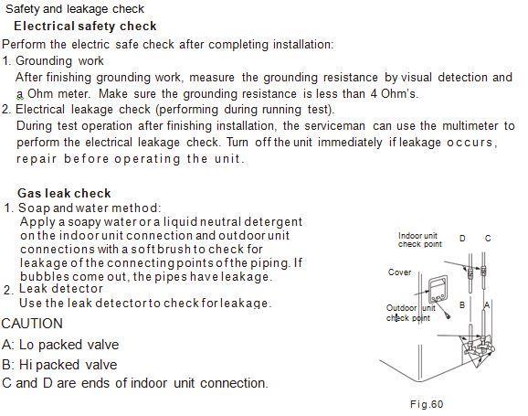
32 31

33 RUNNING TEST Perform test operation after completing gas leak check at the flare nut connections and electrical safety check. Check that all tubing and wiring have been properly connected. Check that the gas and liquid side service valves are fully open. 1. Connect the power, press the ON/OFF button on the remote controller to turn the unit on. 2. Use the MODE button to select COOL, HEAT, AUTO and FAN to check if all the functions work well. 3. When the ambient temperature is too low (lower than 17 C/62 F), the unit cannot be controlled by the remote controller to run in cooling mode, manual operation must be used. 4. Manual operation is used only when the remote controller is disabled or maintenance is necessary. Press the manual control button on the right side of the panel frame to select the AUTO or COOL mode. The unit will operate under Forced AUTO or COOL mode. Run test for 30 minutes minimum. 32


34
Installation Manual ENE ACDC12. Solar Mini-Split Heat Pump System
 Installation Manual ENE ACDC12 Solar Mini-Split Heat Pump System Please read this installation manual completely before installing the product. If the power cord is damaged, replacement must be performed
INSTALLATION MANUAL COMFORT...BUILT TO LAST. 9,000, 12,000 and 18,000 BTU SINGLE-ZONE DUCTLESS MINI-SPLIT SYSTEM Heat Pump
 COMFORT...BUILT TO LAST 9,000, 12,000 and 18,000 BTU SINGLE-ZONE DUCTLESS MINI-SPLIT SYSTEM Heat Pump INSTALLATION MANUAL INDOOR UNIT: 1PAMSH09-SZW-14.5 1PAMSH09-SZW-15 1PAMSH12-SZW-15 1PAMSH18-SZW-15
INVERTER SPLIT - TYPE
 INVERTER SPLIT - TYPE ISSUE No 2 DATE 04/09/08 P/No 2020323A2868 CONTENTS SAFETY PRECAUTIONS Warning 2 Operating temperature 2 BEFORE INSTALLATION Tools needed for installation 3 Items required for installing
ROOM AIR CONDITIONER INSTALLATION MANUAL
 ROOM AIR CONDITIONER INSTALLATION MANUAL (Inverter Split Type) Please read this installation manual completely before installing the product When the power cord is damaged, replacement work shall be performed
SPLIT-TYPE ROOM AIR CONDITIONER
 Before using your air conditioner, please read this manual carefully and keep it for future reference SPLIT-TYPE ROOM AIR CONDITIONER Please read this installation manual completely before installing the
Choosing the installation site. Installation. 07 Choosing the installation site
 Installation Installation warnings: 1. Carefully read the installation manual before beginning. 2. Follow each step as shown. 3. Observe all local, state, and national electrical codes and by qualified,
R410A SPLIT SERIES DC INVERTER
 R410A SPLIT SERIES DC INVERTER Models ECO906SD ECO908SD ECO1206SD ECO1208SD ECO1806SD Read This Manual Inside you will find many helpful hints on how to use and maintain your air conditioner properly Just
INVERTER SPLIT -TYPE ROOM AIR CONDITIONER
 Before using your air conditioner, please read this manual carefully and keep it for future reference. INVERTER SPLIT -TYPE ROOM AIR CONDITIONER Please read this installation manual completely before installing
SPLIT -TYPE ROOM AIR CONDITIONER
 Before using your air conditioner, please read this manual carefully and keep it for future reference. SPLIT -TYPE ROOM AIR CONDITIONER iqool9 iqool2 iqool8 iqool24 Please read this installation manual
INVERTER SPLIT - TYPE ROOM AIR CONDITIONER
 Before using your air conditioner, please read this manual carefully and keep it for future reference. INVERTER SPLIT - TYPE ROOM AIR CONDITIONER Please read this installation manual completely before
INVENTER SPLIT -TYPE ROOM AIR CONDITIONER
 Before using your air conditioner, please read this manual carefully and keep it for future reference INVENTER SPLIT -TYPE ROOM AIR CONDITIONER Please read this installation manual completely before installing
DUCTLESS MINI-SPLIT INSTALLATION MANUAL FOR MODELS: 1PAMSHQCW PAMSHQCW12-15 COMFORT...BUILT TO LAST 12,000 BTU / 15 SEER QUICK CONNECT
 COMFORT...BUILT TO LAST 12,000 BTU / 15 SEER QUICK CONNECT DUCTLESS MINI-SPLIT With 11,500 BTU Heat Pump INSTALLATION MANUAL FOR MODELS: 1PAMSHQCW12-15 Indoor Wall Unit 1PAMSHQCW12-15 Outdoor Condenser
Installation. All about the. of your. Split Type Room Air Conditioner. Refer to Page 2 for table of contents.
 All about the Installation of your Split Type Room Air Conditioner Refer to Page 2 for table of contents. www.frigidaire.com USA 1-866-942-1567 www.frigidaire.ca Canada 1-866-942-1567 2020323B2335 (June
SPLIT -TYPE ROOM AIR CONDITIONER
 Before using your air conditioner, please read this manual carefully and keep it for future reference. PLIT -TYPE ROOM AIR CONDITIONER The design and specifications are subject to change without prior
SINGLE - ZONE Ductless Split System Heat Pumps Installation, Operation & Maintenance Manual
 Presents SINGLE - ZONE Ductless Split System Heat Pumps Installation, Operation & Maintenance Manual 9k,12k 18k 24k, 30k, 36k ECR International, Inc. 2201 Dwyer Avenue, Utica NY 13501 Phone: 800.325.5479
INSTALLATION MANUAL. Split-type Air Conditioner (Cooling and Heating) Outdoor Unit UQB09JJWC UQB12JJWC. Indoor Unit AQB09JJWC AQB12JJWC
 Outdoor Unit UQB09JJWC UQB12JJWC. Indoor Unit AQB09JJWC AQB12JJWC") AQB09JJ6WC_IM_E_2585 2006.4.17 4:26 PM Page 17 INSTALLATION MANUAL Indoor Unit AQB09JJWC AQB12JJWC Outdoor Unit UQB09JJWC UQB12JJWC ENGLISH FRANÇAIS ESPAÑOL Split-type Air Conditioner (Cooling and Heating)
AQB09JJ6WC_IM_E_2585 2006.4.17 4:26 PM Page 17 INSTALLATION MANUAL Indoor Unit AQB09JJWC AQB12JJWC Outdoor Unit UQB09JJWC UQB12JJWC ENGLISH FRANÇAIS ESPAÑOL Split-type Air Conditioner (Cooling and Heating)
INSTALLATION MANUAL. Split-type Air Conditioner (Cooling and Heating) Indoor Unit AQB18J6WC AQB24J2WC. Outdoor Unit UQB18J6WC UQB24J2WC
 Indoor Unit AQB18J6WC AQB24J2WC. Outdoor Unit UQB18J6WC UQB24J2WC") AQB8J6WC_IM_E_25864 2006.4.4 3:29 PM Page 7 INSTALLATION MANUAL Indoor Unit AQB8J6WC AQB24J2WC Outdoor Unit UQB8J6WC UQB24J2WC ENGLISH FRANÇAIS ESPAÑOL Split-type Air Conditioner (Cooling and Heating)
AQB8J6WC_IM_E_25864 2006.4.4 3:29 PM Page 7 INSTALLATION MANUAL Indoor Unit AQB8J6WC AQB24J2WC Outdoor Unit UQB8J6WC UQB24J2WC ENGLISH FRANÇAIS ESPAÑOL Split-type Air Conditioner (Cooling and Heating)
SPLIT -TYPE ROOM AIR CONDITIONER
 efore using your air conditioner, please read this manual carefully and keep it for future reference. SPLIT -TYPE ROOM IR CONDITIONER The design and specifications are subject to change without prior notice
- INVERTER SPLIT TYPE ROOM AIR CONDITIONER
 Before using your air conditioner, please read this manual carefully and keep it for future reference. - INVERTER SPLIT TYPE ROOM AIR CONDITIONER SERIES Please read this installation manual completely
Inverter Air Conditioner Installation Manual GIN 090/GIN 091 GIN 120/GIN 121 GIN 180/GIN 181 GIN 240/GIN 241
 Inverter Air Conditioner Installation Manual GIN 090/GIN 091 GIN 120/GIN 121 GIN 180/GIN 181 GIN 240/GIN 241 Please read this user manual first! Dear Customer, Thank you for preferring a Beko product.
TABLE OF CONTENTS. NOTE: Read the entire instruction manual before starting the installation. TROUBLESHOOTING... 13
 R 410A Duct Free Split System Air Conditioner and Heat Pump Product Family: DFS4(A/H) System, DFC4(A/H)3 Outdoor, DFF4(A/H)H Indoor NOTE: Read the entire instruction manual before starting the installation.
Installation Manual. KS Series KS09 KS12 KS18 KS24 KS28. J3387_Kaden_Installer_Manual_ indd 1
 Wall Mounted AIR CONDITIONER Installation Manual KS Series KS09 KS12 KS18 KS24 KS28 J3387_Kaden_Installer_Manual_050917.indd 1 5/09/2017 9:07 AM J3387_Kaden_Installer_Manual_050917.indd 2 5/09/2017 9:07
AOYG18LFC OUTDOOR UNIT INSTALLATION MANUAL INSTALLATION MANUAL. For authorized service personnel only. PART NO
 AOYG8LFC OUTDOOR UNIT INSTALLATION MANUAL INSTALLATION MANUAL For authorized service personnel only. English PART NO. 93778639 93778639_IM.indb /20/20 6:07:25 PM AIR CONDITIONER OUTDOOR UNIT INSTALLATION
SPLIT -TYPE ROOM AIR CONDITIONER
 efore using your air conditioner, please read this manual carefully and keep it for future reference. SPLIT -TYPE ROOM IR CONDITIONER The design and specifications are subject to change without prior notice
Installation Manual SPLIT-TYPE ROOM AIR CONDITIONER
 SPLIT-TYPE ROOM AIR CONDITIONER Installation Manual IMPORTANT NOTE: Read this manual carefully before installing or operating your new air conditioning unit. Make sure to save this manual for future reference.
DUCTLESS MINI-SPLIT INSTALLATION MANUAL COMFORT...BUILT TO LAST
 COMFORT...BUILT TO LAST SINGLE ZONE DUCTLESS MINI-SPLIT INSTALLATION MANUAL 2PAMS SERIES Before using your air conditioner please read this manual carefully and keep it for future reference, along with
FLOOR-STANDING TYPE AIR CONDITIONER INSTALLATION MANUAL
 FLOOR-STANDING TYPE AIR CONDITIONER INSTALLATION MANUAL CONTENTS SAFETY PRECAUTIONS Warning... Caution... INSTALLATION INSTRUCTIONS Accessories...;...3 Selecting installation place...4 PIPE CONNECTION
Installation Manual. WAS / WYS Series. For 9,000-36,000 BTU/hr Systems. Inverter+ and Inverter++ Models
 DUCTLESS MINI SPLIT SYSTEM AIR CONDITIONER / HEAT PUMP WAS / WYS Series WAS: Cooling Only Version WYS: Cooling and Heating Version Inverter+ and Inverter++ Models For 9,000-36,000 BTU/hr Systems Installation
Installation and Operation Manual. SVH Series. Inverter Single Zone Ductless Mini-Split SVH09SA-0 SVH09SA-1 SVH12SA-0 SVH12SA-1 SVH18SA-1 SVH24SA-1
 Installation and Operation Manual SVH Series Inverter Single Zone Ductless Mini-Split SVH09SA-0 SVH09SA-1 SVH12SA-0 SVH12SA-1 SVH18SA-1 SVH24SA-1 www.marsdelivers.com Table of Contents Installation Manual
Installation and Operation Manual. CMA12SB-0 Series. Horizontal/Side Discharge Condensing Units
 Installation and Operation Manual CMA12SB-0 Series Horizontal/Side Discharge Condensing Units 517.787.2100 www.marsdelivers.com www.heatcontroller.com Heat Controller CONTENTS PAGE 1. PRES... 1 2. INSTALLATION
Installation Manual. Aurora Series All Model Numbers SPLIT-TYPE ROOM AIR CONDITIONER CS
 SPLIT-TYPE ROOM AIR CONDITIONER Installation Manual Aurora Series All Model Numbers IMPORTANT NOTE: Read this manual carefully before installing or operating your new air conditioning unit. Make sure to
DLCLRA. INSTALLATION INSTRUCTIONS Outdoor Unit Single Zone Ductless System Sizes 36 to 58 TABLE OF CONTENTS
 DLCLRA INSTALLATION INSTRUCTIONS Outdoor Unit Single Zone Ductless System Sizes 36 to 58 Fig. 1 - Size 36 TABLE OF CONTENTS PAGE SAFETY CONSIDERATIONS... 2 PARTS LIST... 3 SYSTEM REQUIREMENTS... 4 WIRING...
Please read this manual carefully before installation and keep it for future reference. CONTENTS. Installation Manual. DIY Series
 Please read this manual carefully before installation and keep it for future reference. CONTENTS Installation Manual DIY Series The design and specifications are subject to change without prior notice.
QUICK CONNECT INSTALLATION MANUAL DUCTLESS MINI-SPLIT SYSTEM FOR MODELS: 2PAMSHQC12 2PAMSHQC18 2PAMSHQC24 2PAMSHQC36
 QUICK CONNECT DUCTLESS MINI-SPLIT SYSTEM INSTALLATION MANUAL FOR MODELS: 2PAMSHQC12 2PAMSHQC18 2PAMSHQC24 2PAMSHQC36 Before using your air conditioner, please read this manual carefully and keep it for
HEAT PUMP INSTALLATION MANUAL
 DUCTLESS INVERTER HEAT PUMP INSTALLATION MANUAL Models: TERRA09HP230V1A TERRA12HP230V1A TERRA18HP230V1B TERRA24HP230V1B Thank you for choosing a Gree Terra Ductless Heat Pump for your customer. Please
Installation Manual. Forest Series All Model Numbers SPLIT-TYPE ROOM AIR CONDITIONER
 SPLIT-TYPE ROOM AIR CONDITIONER Installation Manual Forest Series All Model Numbers IMPORTANT NOTE: Read this manual carefully before installing or operating your new air conditioning unit. Make sure to
INSTALLATION MANUAL SPLIT TYPE ROOM AIR CONDITIONER (PART NO )
") SPLIT TYPE ROOM AIR CONDITIONER INSTALLATION MANUAL (PART NO. 9312791019-01) This air conditioner uses new refrigerant HFC (R410A). The basic installation work procedures are the same as conventional refrigerant
SPLIT TYPE ROOM AIR CONDITIONER INSTALLATION MANUAL (PART NO. 9312791019-01) This air conditioner uses new refrigerant HFC (R410A). The basic installation work procedures are the same as conventional refrigerant
Installation Manual. KSIF Series All Model Numbers SPLIT-TYPE ROOM AIR CONDITIONER
 SPLIT-TYPE ROOM AIR CONDITIONER Installation Manual KSIF Series All Model Numbers IMPORTANT NOTE: Read this manual carefully before installing or operating your new air conditioning unit. Make sure to
Installation Manual Forest Series All Model Numbers
 SPLIT-TYPE ROOM AIR CONDITIONER Installation Manual Forest Series All Model Numbers CS78421-548-754 IMPORTANT NOTE: Read this manual carefully before installing or operating your new air conditioning unit.
Installation Manual. SYSPLIT WALL FLEXI Series SPLIT-TYPE ROOM AIR CONDITIONER
 SPLIT-TYPE ROOM AIR CONDITIONER Installation Manual SYSPLIT WALL FLEXI Series IMPORTANT NOTE: Read this manual carefully before installing or operating your new air conditioning unit. Make sure to save
FLCH4R Garage and Utility Electric Heater
 FLCH4R Garage and Utility Electric Heater Installation, Operation & Maintenance Instructions Model No. Volts Amps Watts BTU/HR Phase High Low High Low High Low Min Fuse Size* FLCH4R 208 17.3 8.66 3600
DVC/DVH Series. Inverter Single Zone Ductless Mini-Split A-DVC/DVH 09SF A-DVC/DVH 12SF A-DVC/DVH 18SF A-DVC/DVH 24SF
 Installation Manual DVC/DVH Series Inverter Single Zone Ductless Mini-Split A-DVC/DVH 09SF A-DVC/DVH 12SF A-DVC/DVH 18SF A-DVC/DVH 24SF B-DVC/DVH 09SF B-DVC/DVH 12SF B-DVC/DVH 18SF B-DVC/DVH 24SF www.marsdelivers.com
R32. Installation Manual Split Type Wall Mounted Air Conditioner. This appliance shall be installed in accordance with: REFRIGERANT
 SWING LRSWING Installation Manual Split Type Wall Mounted Air Conditioner COOL RUN C SPEED TURBO ON/OFF FAN COOL HEAT SWING SWING Rinnai Systems Models System Indoor Outdoor HSNRQ25B HINRQ25B HONRQ25B
Installation Instructions
 40MBFQ Floor Console Ductless System Sizes 09 to 58 Installation Instructions TABLE OF CONTENTS PAGE SAFETY CONSIDERATIONS... 2 PARTS LIST... 3 SYSTEM REQUIREMENTS... 4 WIRING... 4 DIMENSIONS... 5 CLEARANCES...
Installation Manual. Aurora Series All Model Numbers SPLIT-TYPE ROOM AIR CONDITIONER
 SPLIT-TYPE ROOM AIR CONDITIONER Installation Manual Aurora Series All Model Numbers 2925CP65 292CP565 2925CP66 292CP566 2925CP67 292CP567 2925CP68 292CP568 CS78421-548-754 IMPORTANT NOTE: Read this manual
Air Conditioner Service Manual KSWT SERIES INSTALLATION INSTRUCTION. Wall-mounted Split Type
 KSWT SERIES INSTALLATION INSTRUCTION Wall-mounted Split Type INSTALLATION 1. Characteristics of refrigerant 1.1 Temperature-pressure relationships in saturated condition Pressure (kg/cm2 G) 35 30 25 20
[FLARE CONNECTION TYPE] ATTENTION
![[FLARE CONNECTION TYPE] ATTENTION](/thumbs/88/117511702.jpg "[FLARE CONNECTION TYPE] ATTENTION") SPLIT-TYPE AIR CONDITIONERS Model MXZ-2A20NA [FLARE CONNECTION TYPE] HFC utilized R410A INSTALLATION MANUAL ATTENTION This manual mentions how to install only the outdoor unit, MXZ-2A20NA. As for the way
SPLIT-TYPE AIR CONDITIONERS Model MXZ-2A20NA [FLARE CONNECTION TYPE] HFC utilized R410A INSTALLATION MANUAL ATTENTION This manual mentions how to install only the outdoor unit, MXZ-2A20NA. As for the way
Installation Instructions
 40MAQ High Wall Ductless Split System Sizes 09 to 36 Installation Instructions NOTE: Read the entire instruction manual before starting the installation TABLE OF CONTENTS PAGE SAFETY CONSIDERATIONS 2 PARTS
1. BEFORE INSTALLATION
 ENGLISH SPLIT-TYPE AIR CONDITIONERS INSTALLATION MANUAL MSZ-D30/36NA MSY-D30/36NA JG79A061H01 Phillips screwdriver Level Scale Utility knife or scissors 3 in. (75 mm) hole saw Torque wrench Wrench (or
Installation Instructions
 38MHR Outdoor Unit Single Zone Ductless System Sizes 09 to 24 Installation Instructions NOTE: Read the entire instruction manual before starting the installation. NOTE: Images are for illustration purposes
FLOOR-STANDING SPLIT TYPE ROOM AIR CONDITIONER
 Before using your air conditioner, please read this manual carefully and keep it for future reference. FLOOR-STANDING SPLIT TYPE ROOM AIR CONDITIONER Please read this installation manual completely before
Installation Instructions
 40MBFQ Floor Console Ductless System Sizes 09 to 12 Installation Instructions TABLE OF CONTENTS PAGE SAFETY CONSIDERATIONS... 2 PARTS LIST... 3 SYSTEM REQUIREMENTS... 4 DIMENSIONS... 5 CLEARANCES... 5
DLCSRA. INSTALLATION INSTRUCTIONS Outdoor Unit Ductless Split System Sizes 09 to 36 TABLE OF CONTENTS
 DLCSRA INSTALLATION INSTRUCTIONS Outdoor Unit Ductless Split System Sizes 09 to 36 NOTES: Read the entire instruction manual before starting the installation. Images are for illustration purposes only.
AIR CONDITIONER CONSOLE
 Installation manual ENGLISH AIR CONDITIONER CONSOLE English Indoor unit console type IT IS MANDATORY TO CUT OFF POWER SUPPLY BEFORE STARTING TO WORK IN THE ELECTRIC CASING BOXES. GENERAL RECOMMENDATIONS
1. BEFORE INSTALLATION
 ENGLISH SPLIT-TYPE AIR CONDITIONERS INSTALLATION MANUAL MSZ-D30/36NA MSY-D30/36NA JG79A061H09 Phillips screwdriver Level Scale Utility knife or scissors 3 in. (75 mm) hole saw Torque wrench Wrench (or
DAIKIN AIR CONDITIONER
 3P226011-1A M07B242A DAIKIN AIR CONDITIONER Two-dimensional bar code is a code for manufacturing. Safety Precautions (1) Read these Safety Precautions carefully to ensure correct installation. This manual
MULTI TYPE ROOM AIR CONDITIONERS INSTALLATION INSTRUCTIONS
 MULTI TYPE ROOM IR CONDITIONERS INSTLLTION INSTRUCTIONS Please read this instruction sheet completely before installing the product. When the power cord is damaged, replacement work shall be performed
Installation Manual. All Model Numbers SERIES SPLIT-TYPE ROOM AIR CONDITIONER
 SERIES SPLIT-TYPE ROOM AIR CONDITIONER Manual All Model Numbers IMPORTANT NOTE: Read this manual carefully before installing or operating your new air conditioning unit. Make sure to save this manual for
Installation Manual. Oasis Series All Model Numbers SPLIT-TYPE ROOM AIR CONDITIONER CS
 SPLIT-TYPE ROOM AIR CONDITIONER Installation Manual Oasis Series All Model Numbers CS78421-548-754 IMPORTANT NOTE: Read this manual carefully before installing or operating your new air conditioning unit.
Installation Instructions
 8GXM / 0GXM Multi---Split High---Wall Duct Free Split System 8GXM --- Size 18k, k, and 0k 0GXM --- Size 9k, 1k, and 18k Installation Instructions NOTE: Read the entire instruction manual before starting
Ductless Split Air Conditioner
 Ductless Split Air Conditioner Installation Manual Indoor HSU09VHG(DB)-W HSU12VHG(DB)-W HSU18VHH(DB)-W HSU24VHG(DB)-W Outdoor HSU09VHG(DB)-G HSU12VHG(DB)-G HSU18VHH(DB)-G HSU24VHG(DB)-G Table of Contents
Inverter Air Conditioner Installation Manual
 Inverter Air Conditioner Installation Manual KSV25CRG, KSV35CRG, KSV70CRG, KSV25HRG, KSD25HRG, KSV35HRG, KSD35HRG, KSV50HRG, KSD50HRG, KSV70HRG, KSD70HRG, KSV80HRG, KSD80HRG Congratulations Contents Congratulations
R32 INSTALLATION MANUAL ENGLISH AIR CONDITIONER (SPLIT TYPE) Indoor unit RAS-10PKVPG-E RAS-13PKVPG-E RAS-16PKVPG-E
 Indoor unit RAS-10PKVPG-E RAS-13PKVPG-E RAS-16PKVPG-E") R32 INSTALLATION MANUAL AIR CONDITIONER (SPLIT TYPE) ENGLISH Indoor unit RAS-10PKVPG-E RAS-13PKVPG-E RAS-16PKVPG-E Outdoor unit RAS-10PAVPG-E RAS-13PAVPG-E RAS-16PAVPG-E 1121451198 EN CONTENTS PRES FOR
R32 INSTALLATION MANUAL AIR CONDITIONER (SPLIT TYPE) ENGLISH Indoor unit RAS-10PKVPG-E RAS-13PKVPG-E RAS-16PKVPG-E Outdoor unit RAS-10PAVPG-E RAS-13PAVPG-E RAS-16PAVPG-E 1121451198 EN CONTENTS PRES FOR
1. BEFORE INSTALLATION
 ENGLISH SPLIT-TYPE AIR CONDITIONERS INSTALLATION MANUAL JG79A191H07 MSZ-GE06/09/12/15/18NA MSY-GE09/12/15/18NA When installing multi units, refer to the installation manual of the multi unit for outdoor
MN908 No. 282C Replaces 282B LB7013
 No. 282C Replaces 282B LB7013 Instruction Manual For Baldor Dust Control Units Models DC7, DC7 3, DC8, DC8 3, DC10, DC10 3, DC12, DC12 3 and DC14 3. For use on Grinders mounted to GA16 and GA20 pedestals
Installation Instructions
 40MHH High Wall Ductless System Sizes 09 to 24 Installation Instructions NOTE: Read the entire instruction manual before starting the installation. NOTE: Images are for illustration purposes only. Actual
GARAGE HEATER WITH REMOTE INSTRUCTION MANUAL MODEL: HA24-100E HA24-150E. Figure 1
 GARAGE HEATER WITH REMOTE INSTRUCTION MANUAL MODEL: HA24-100E HA24-150E Figure 1 PET OWNERS WARNING: Health warning for some small pets, including birds, as they are extremely sensitive to the fumes produced
CENTRAL AIR CONDITIONER SPLIT SYSTEM
 CENTRAL AIR CONDITIONER SPLIT SYSTEM WITH ELECTRONIC CONTROL SERIES: DS INSTALLATION INSTRUCTIONS INDEX GENERAL... 2 UNIT LOCATION CRITERIA... 2 DIMENSIONAL DRAWINGS... 3 INDOOR UNIT INSTALLATION... 5
Installation Instructions
 38MGQ Multi-Zone Ductless System Sizes 18, 27, 36 and 48 Installation Instructions NOTE: Read the entire instruction manual before starting the installation. TABLE OF CONTENTS PAGE SAFETY CONSIDERATIONS...
Installation Instructions
 40MAQ High Wall Ductless System Sizes 09 to 36 Installation Instructions NOTES: Read the entire instruction manual before starting the installation. Images are for illustration purposes only. Actual models
Horizontal/Side Discharge Condensing Units
 INSTALLATION, OPERATION & MAINTENANCE MANUAL Horizontal/Side Discharge Condensing Units Models CMA12SD-0 CMA18SD-1 CMA24SD-1 CMA30SD-1 CMA36SD-1 CMA48SD-1 517.787.2100 www.marsdelivers.com Horizontal/Side
BR342 Ducted Installation Instructions Australian Version Electronic Wall Control
 Australian Version Electronic Wall Control 1 Introduction The BR342 reverse cycle rooftop air-conditioner is designed for installation onto Recreational Vehicles (RV s) at the time of manufacture or as
Installation Instructions
 38MPRA Outdoor Unit Single Zone Ductless System Sizes 09 to 12 Installation Instructions NOTES: Read the entire instruction manual before starting the installation. Images are for illustration purposes
Installation Instructions. For the 18 Built-In Dishwasher and Front Color Panels
 Installation Instructions For the 18 Built-In Dishwasher and Front Color Panels Printed in USA 154232102 Before You Begin DO NOT INSTALL DISHWASHER UNTIL YOU HAVE READ ALL INSTRUCTIONS. FOR YOUR SAFETY,
Installation Instructions
 40MAQ / 38MAQ 619PB / 538PR High---Wall Ductless Split System Sizes 09 to 30 Installation Instructions TABLE OF CONTENTS PAGE PARTS LIST... 2 SAFETY CONSIDERATIONS... 3 SYSTEM REQUIREMENTS... 4 DIMENSIONS...
HI Industrial Utility Heater HI Soleus Air International
 HI1-50-03 Industrial Utility Heater HI1-50-03 2010 Soleus Air International Thank you for choosing a Soleus Air Utility Heater. This owner s manual will provide you with valuable information necessary
Installation Instructions
 Installation Instructions For Fully Integrated NoFrost Combined Refrigerator-Freezers HCB 1560/1561 7084 429-00 Important Please read and follow these instructions These instructions contain Danger, Warning
VMH09/12/18/24 SU Series
 Installation and Operation Manual VMH09/12/18/24 SU Series Inverter Single Zone Ductless Mini-Split 517.787.2100 www.marsdelivers.com www.heatcontroller.com TABLE OF CONTENTS Safety Precautions Warnings
Notices for installation
 Notices for installation Important Notices Before installing, please contact with local authorized maintenance center, if unit is not installed by the authorized maintenance center, the malfunction may
Installation Manual PMV Kit RBM-PMV0363E RBM-PMV0903E
 EB99802801-1 Installation Manual RBM-PMV0363E RBM-PMV0903E Installation Manual English OUTDOOR UNIT SIDE UPPER INDOOR UNIT SIDE Thank you very much for purchasing TOSHIBA Air conditioner. Please read this
DLCMRA. INSTALLATION INSTRUCTIONS Multi zone Outdoor Unit Ductless System Sizes 18, 27, 36 and 48 TABLE OF CONTENTS PAGE SAFETY CONSIDERATIONS...
 DLCMRA INSTALLATION INSTRUCTIONS Multi zone Outdoor Unit Ductless System Sizes 18, 27, 36 and 48 TABLE OF CONTENTS PAGE SAFETY CONSIDERATIONS... 2 GENERAL... 2 PARTS LIST... 3 SYSTEM REQUIREMENTS... 4
1. BEFORE INSTALLATION
 ENGLISH SPLIT-TYPE AIR CONDITIONERS INSTALLATION MANUAL MSZ-FH09/12/15NA JG79A805H01 When installing multi units, refer to the installation manual of the multi unit for outdoor unit installation. Phillips
Sundance Spas SPA EQUIPMENT SYSTEM. Installation Instructions. P/N Rev. A
 Sundance Spas SPA EQUIPMENT SYSTEM Installation Instructions P/N 6530-456 Rev. A Contents Important Notices 1 Important Safety Instructions 2 Where to Place the Equipment System 3 Connecting Pipes Between
INVERTER ONE-TWO/ONE-THREE/ONE-FOUR/ONE-FIVE SPLIT-TYPE AIR CONDITIONER
 INVERTER ONE-TWO/ONE-THREE/ONE-FOUR/ONE-FIVE SPLIT-TYPE AIR CONDITIONER Installation Manual IMPORTANT NOTE: Read this manual carefully before installing or operating your new air conditioning unit. Make
Split Air Conditioner
 Change for Life Split Air Conditioner Installation Manual Residential Air Conditioners MODEL: GWC09AB-D3DNA2D GWC12AB-D3DNA2D GWC18AC-D3DNA2D GWC24AC-D3DNA2D GWH09AB-D3DNA2D GWH12AB-D3DNA2D GWH18AC-D3DNA2D
Installation Instructions
 38MGR Multi-zone Outdoor Unit Ductless System Sizes 18, 24, 30, 36 and 48 Installation Instructions TABLE OF CONTENTS PAGE SAFETY CONSIDERATIONS... 2 GENERAL... 2 PARTS LIST... 3 SYSTEM REQUIREMENTS...
R32 AIR CONDITIONER HIGH WALL MOUNTED INSTALLATION MANUAL. English DC INVERTER IMPORTANT NOTE: Indoor unit high wall mounted HRD
 INSTALLATION MANUAL ENGLISH AIR CONDITIONER HIGH WALL MOUNTED DC INVERTER R32 English Indoor unit high wall mounted HRD IMPORTANT NOTE: Read this manual carefully before installing or operating your new
OWNER S AND INSTALLATION MANUAL RAV-480FS2B/RAV-480AS2B RAV-600FS8B/RAV-600AS8B
 OWNER S AND INSTALLATION MANUAL RAV-480FS2B/RAV-480AS2B RAV-600FS8B/RAV-600AS8B P/N: 52FS2B54070-R CONTENTS PRECAUTIONS Important Safety Information Hints For Economical Operation Standard Safety Instructions
Mini-Split Air Conditioner
 Cassette Type Installation Manual New Released A-Cassette-600 Mini-Split Air Conditioner DC Inverter Cassette Type Unit All Model Numbers Table of Contents Installation Manual 2 3 Accessories... 04 Safety
Installation Instructions
 Installation Instructions For Fully Integrated NoFrost Combined Refrigerator-Freezers HC 2060/2061 7082 485-00 Important PLEASE READ AND FOLLOW THESE INSTRUCTIONS These instructions contain Warning and
INSTALLATION INSTRUCTIONS
 INSTALLATION INSTRUCTIONS - Wall-mount indoor unit - OPERATING LIMITS Cooling Maximum conditions Heating Maximum conditions Outdoor temperature : 122 F (50 C) D.B. Outdoor temperature : 75 F (24 C) D.B.
Installation Instructions
 Installation Instructions For Fully Integrated NoFrost Combined Refrigerator-Freezers HC 2062 HCB 2062 HC/HCB 20 7082 373-00 Important PLEASE READ AND FOLLOW THESE INSTRUCTIONS These instructions contain
Ductless S plit Air Conditioner
 Ductless S plit Air Conditioner Installation M anual Indoor AW09ES2VH* AW12ES2VH* AW18ES2VH* AW24ES2VH* AW09TE1VH* AW12TE1VH* AW18TE2VH* AW24TE2VH* Outdoor 1U09ES2VHA 1U12ES2VHA 1U18ES2VHA 1U24ES2VHA 1U09TE1VHA
Air Conditioner. user installation & manual manual. imagine the possibilities
 ARFSSSBWK Series ARFSSSCUR AJ JNADCH Series Air Conditioner user installation & manual manual This manual is made with 100% recycled paper. imagine the possibilities Thank you for purchasing this Samsung
DISHWASHER. Models DW2432 and DW2432SS. Installation Manual. Write Serial Number (on inner door of unit) here:
 here:") DISHWASHER Models DW2432 and DW2432SS Installation Manual Write Serial Number (on inner door of unit) here: Felix Storch, Inc. Summit Appliance Division 770 Garrison Avenue Bronx, New York 10474 www.summitappliance.com
DISHWASHER Models DW2432 and DW2432SS Installation Manual Write Serial Number (on inner door of unit) here: Felix Storch, Inc. Summit Appliance Division 770 Garrison Avenue Bronx, New York 10474 www.summitappliance.com
INSTALLATION MANUAL. R410A Split Series. Models RXS15LVJU RXS18LVJU. Installation manual R410A Split series. Manuel dinstallation Série split R410A
 INSTALLATION MANUAL R410A Split Series Installation manual R410A Split series English Manuel dinstallation Série split R410A Français Manual de instalación Serie Split R410A Español Models RXS15LVJU RXS18LVJU
Installation Instructions
 Installation Instructions For Fully Integrated NoFrost Combined Refrigerator-Freezers HCB 1560/1561 HC 1550 7084 327-00 Important Please Read and Follow these Instructions These instructions contain Danger,
Installation Instructions
 Installation Instructions For Fully Integrated NoFrost Combined Refrigerator-Freezers HC 2062 HCB 2062 HC/HCB 2062 7084 445-00 Important Please read and follow these instructions These instructions contain
INSTALLATION MANUAL. R410A Split Series. Model RXS24LVJU. Installation manual R410A Split series. Manual de instalación Serie Split R410A.
 INSTALLATION MANUAL R410A Split Series Installation manual R410A Split series English Français Manual de instalación Serie Split R410A Español Model RXS24LVJU Safety Precautions Read these Safety Precautions
UltraV Series Outdoor Units
 INSTALLATION MANUAL UltraV Series Outdoor Units Models A-VMH18DU-1 A-VMH28TU-1 A-VMH36QU-1 517.787.2100 www.marsdelivers.com Table of Contents Installation Manual 1 2 3 4 5 Accessories... 4 Safety Precautions...