Installation & Operation Manual For ENERGENICS In-Line Space Saver Lint Filters
|
|
|
- Byron Fleming
- 5 years ago
- Views:
Transcription
 643-1711 Fax: (239) 643-6081 Customer Service: (800) 944-1711 Descriptions Installation & Operation Manual For ENERGENICS In-Line Space")
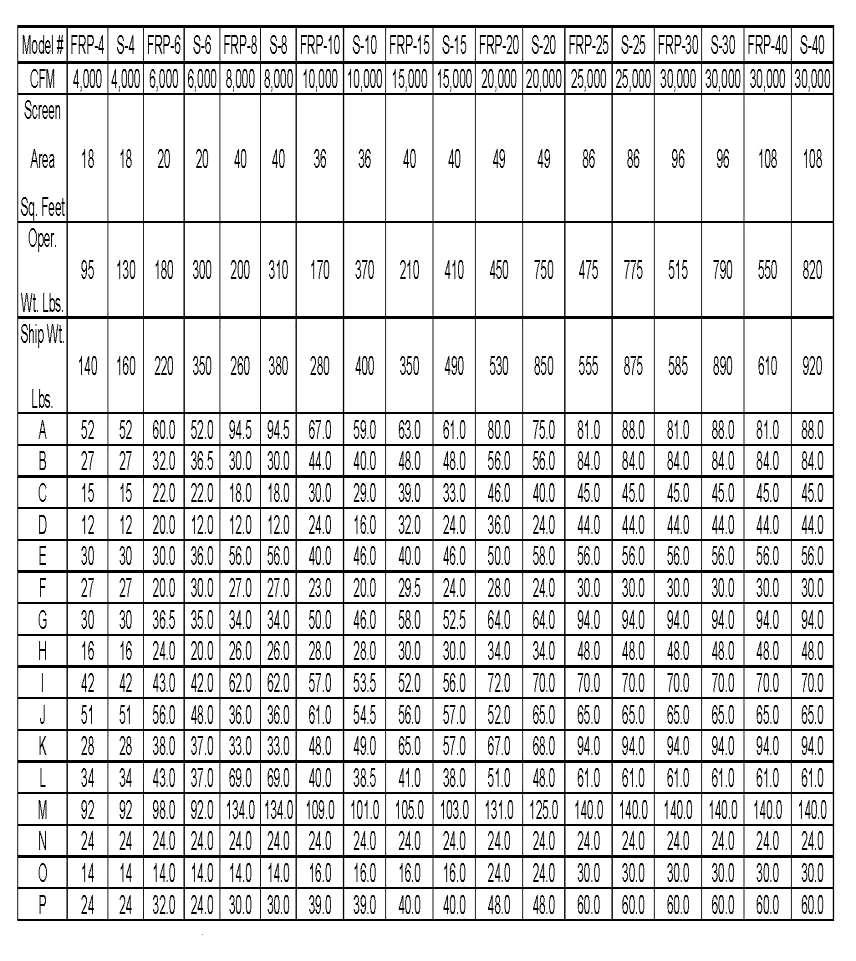
1 Don Street Naples, Florida Telephone: (239) Fax: (239) Customer Service: (800) Descriptions Installation & Operation Manual For ENERGENICS In-Line Space Saver Lint Filters Page Table of Contents 1 Description of Lint Filter Operation 2 Lint Filter Control Sequence of Operation 3 Receiving and Installation 4 Important Installation Considerations 5 Warnings/Cautions 6 Dimensional Drawing 7 Dimensional Table 8 Typical Installation Without Optional AFO (Booster Fan) 9 Typical Installation With Optional AFO (Booster Fan) 10 Utilities Installation 11 Sheet Metal Installation 12 Compressed Air Requirements 13 Fire Suppression Water System (optional) 14 Proper Application with Booster Fans & Variable Frequency Drives Control Installation Instructions: Omron Obsolete UL Control Schematic & Wiring Diagram 16 IDEC Obsolete UL Control Schematic & Wiring Diagram 17 IDEC UL PLC CONTROL IDEC UL PLC Control Schematic & Wiring Diagram 18 Change Blowdown & Excess Pressure Set-Point 19 Change Timed Blowdown Intervals 20 Disable Blowdown when all Dryers turn off 21 Tubing Connections (Shown with Optional Airflow Optimizer if Ordered) 22 Connection Requirement Connection Requirement (Side View) Maintenance Requirements 25 1
2 DESCRIPTION OF LINT FILTER OPERATION Your new Energenics Lint Filter operated with a UL approved control represents the most advanced features available in the laundry industry to date. The following list the functions and mode of operation: Blowdown (cleaning) The Lint Filter will monitor the system backpressure and automatically initiate the blowdown cycle. As the screen loads with lint, the back pressure will increase and will result in an automatic blowdown (cleaning) when the backpressure reaches a set reference (default is.5 w.c.). The lint filter will also blowdown at the end of every dryer cycle to insure complete screen cleaning when dryers are turned off. 70% of the lint will be removed from the screen even though the dryer(s) may be operating. During the blowdown with dryers off, 100% of the lint will be removed from the screen. A manual blowdown can also be done by depressing the button on the bottom of the Lint Filter control. Note that automatic blowdown cannot occur within 20 seconds of a prior blowdown. This is done to allow the compressed air supply to partially recover. Optional Excess Pressure Alarm If for any reason the Lint Filter has not blown down properly (i.e.: compressor turned off) the system will sense a higher backpressure than normal. In this event the siren and the strobe light both activate. The Filter control will attempt to blowdown every 20 seconds until the excess backpressure condition has terminated. If this condition persists, a manual inspection of the lint screen and observation of proper blowdown must be done. Optional Fire Control System A normally open sensor located inside of the filter at the top of the inlet will close at 275 degrees F. The control will open the water solenoid, illuminate the strobe as well as energize the siren. The alarm will be active until 30 seconds after the temperature has dropped below 275 degrees F. After 30 seconds the alarm will automatically reset. Inside the control box is a Fire Control test button. Depress the button and the Fire Control will be activated for the duration the button is pressed. The function of the test button is to check the circuit. It does not test the sensor itself. Using a propane torch to the sensor will test the complete system. 2
3 LINT FILTER CONTROL SEQUENCE OF OPERATION 1. Dryers Operating When backpressure reaches the field adjustable setpoint (default.7 W.C.) the air blowdown solenoid is activated for 10 seconds. There is a field adjustable delay (default 10 seconds) before the blowdown will occur. The air solenoid will continue to activate for 10 seconds at 3 minute intervals until backpressure is below the field adjustable setpoint. The 3 minute interval will allow the compressor to refill. 2. Dryers Excess Pressure Alarm When Operating When backpressure reaches the field adjustable setpoint (default 1.5 W.C.) the warning indicator horn and light will be activated continuously until the backpressure drops below the field adjustable setpoint. 3. After Dryers Turn Off When backpressure drops to 0 W.C. the air blowdown solenoid is activated for 10 seconds. There is a field adjustable delay (default 10 seconds) before the blowdown will occur This should occur only 1 time when all the dryers are off. This should reset only when 1 or more dryers turn on and not until the backpressure reaches.7 W.C. (Field Adjustable). 4. Manual Blowdown Operation When the button on the bottom of the filter control is depressed, the air blowdown solenoid is activated for 10 seconds. The control will require 3 minutes before another manual blowdown can be completed. 5. Fire Control If the temperature exceeds 260 degrees Fahrenheit the water solenoid will open and the warning indicator horn and light will be activated continuously until the temperature goes below 260 degrees Fahrenheit for 30 seconds. At which point the fire control will completely reset. 6. Manual Fire Control Test Inside the filter control is a black button. When the button is depressed the water solenoid will open and the warning indicator horn and light will be activated as long as the button is pressed. 7. Timed Interval Blowdown At a timed interval (default 2 hours) the air blowdown solenoid is activated for 10 seconds. 8. Optional Vacuum Output When the Air Solenoid is activated a 24 VDC output on Blowdown 2 activates. If the lint filter is equipped with the Energenics lint evacuation vacuum system this operates the vacuum system and opens the gate valve on the filter for 20 seconds. The timer starts at the same time the air solenoid is activated. OUTPUTS FROM FILTER CONTROL Q1-Water Solenoid Valve Q2-Air Solenoid Valve Q3-Optional Vacuum Output 3
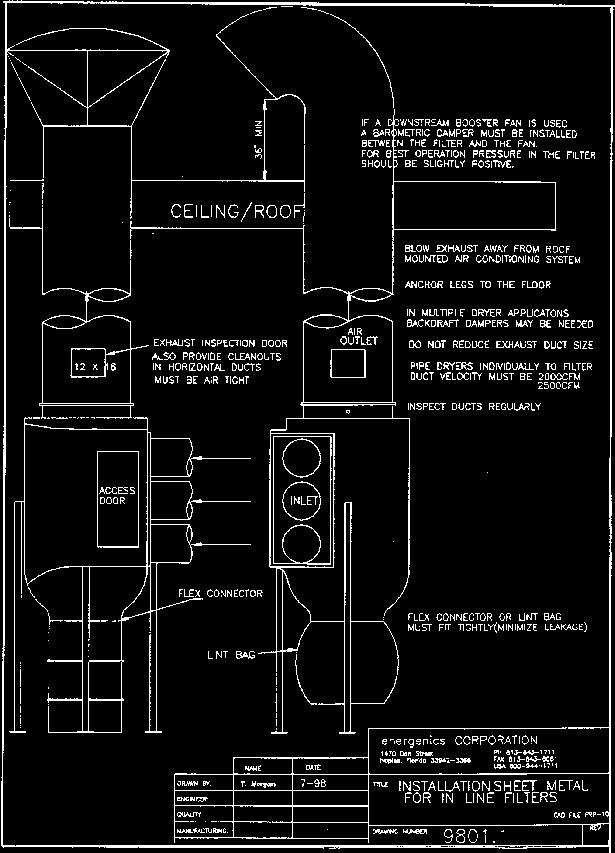
4 RECEIVING AND INSTALLATION Before you sign the Bill of Lading: 1. Receiving- Inspect units inside and out for signs of damage Verify all components are delivered per the Bill of Materials. Report damage to the carrier IMMEDIATELY. Note ALL damage on the Bill of Lading. This is your responsibility and you must file all claims. The filter is fully assembled and ready for installation. The control, valves, and lint bag are in the cardboard box. 2. Installation- Follow instructions herein: Determine the location with reference to minimum duct work from the dryer and ease of access for inspection. If using a lint drop pipe allow enough room for lint to travel down 4 before the first bend. Max bend angle is 30 degrees. If using lint bag or container make sure adequate clearance is allowed. Conduit or Sealtight between filter junction boxes should be ¾ inch. Dependant on options ordered, not all outputs will have connected components. If the Fire Control Option is NOT ordered the installer must supply a junction box to connect the wires from the solenoid valve to the Control Box. When mounting the filter overhead, mount the control below the filter where it can be easily accessed. If this Lint Filter has a downstream fan, do not use the supplied lint bag. You must use a flexible connector and rigid drum (drum sourced locally). If we supplied the fan then we will have the flexible connector in the box. 4
5 IMPORTANT INSTALLATION CONSIDERATIONS All Energenics Lint Collectors can be mounted indoors or outdoors. If it is mounted outdoors we recommend our Side Discharge or a field installed swept radius elbow (Gooseneck). Do not use a conical cap on the filter exhaust discharge. All solenoid valves should be located inside the building. Also, mount the supplied air pressure gauge at the blowdown pipe on top of the filter. All solenoids should be mounted as close to the filter as possible, but ALWAYS inside the building. This will allow most of the air and water (if equipped with optional Fire Control) piping to remain pressure charged for most efficient operation. All wiring should be a minimum of 18 gauge for proper operation. The Filter Control box should be located in a position to be easily seen and in close proximity to personnel. In other words if the Filter Control is located outdoors, 20 feet in the air or in another room away from the laundry personnel, this would be the wrong location. Lint Filter controls should never be mounted outdoors. Since the Filter uses compressed air it is important that the air receiver (if equipped) be located as close to the filter as possible. The longer the pipe runs the more restrictive. You will need to increase the pipe diameter if the run is very long (e.g.: 60 feet). If the installation is a multi-dryer/multi-duct installation it may be necessary to use backdraft dampers to prevent lint backflow into the ducts of turned off dryers. Most dryers have them available as standard equipment or can be ordered to add on. After everything is mounted and utilities turned on press the manual blowdown button located on the bottom of the Filter Control. The rotor on the inside the lint filter should spin. Make sure that the air pressure at the filter starts out at 100 and ends at about 60 at the end of the blowdown cycle. If it is too low the rotor won t turn. If the Filter is equipped with Fire Suppression, the test button is on the inside of the Filter Control. It is on the inside to keep people from pushing the button as they walk by. When the button is pushed the strobe and siren will go on along with the water solenoid valve. The system operates until the button is no longer depressed. 5
6 WARNINGS AND CAUTION You have purchased the finest lint filter available for your facility. Please follow these instructions to ensure a safe long life for your filter and facility. FAILURE TO FOLLOW THESE INSTRUCTIONS CAN RESULT IN AN UNSAFE OPERATING CONDITION, INCLUDING THE POSSIBILITY OF FIRE. DO NOT OPERATE ANY DRYER CONNNECTED TO THIS FILTER WITHOUT BEING CERTAIN THE FILTER STARTUP HAS BEEN COMPLETED AND THE FILTER IS IN OPERATING CONDITION. Insure it is installed in compliance with local codes. Step 1. Install the compressed air (Fire suppression plumbing if ordered), and piping system(s) including solenoid valves. If the filter is in position, make all final connections. Step 2. Mount the 007 control in a visible location on a solid vibration free surface and connect all components. Step 3. Provide dedicated V single phase electrical service to the PLC and test all systems Step 4. Install sheet metal and ducting. START UP AND OPERATION INSTRUCTIONS Inspect the filter installation. Is it complete? Review the entire installation requirements prior to startup. 1. Verify the 007 control wiring. 2. Test the blow down cycle (push manual button on control). Watch the pressure gauge. It should start around 100psi and should not drop below 60psi during the 10 second cycle. The rotor should turn 6-12 times during blow down. The rotor propulsion is adjustable by increasing the number of horizontal holes on the top horizontal portion of the rotor end. 3. Review maintenance requirements and establish a regular PM schedule. CAUTION - DO NOT OPERATE FILTER WITH BOOSTER FAN WITHOUT BAROMETRIC DAMPER OR VARIABLE SPEED DRIVE!!!!!!!! (CONSULT PAGE 15) 6
7 7
8 8
9 9
10 10
11 11
12 12
13 13
14 14
15 Service Bulletin #2 August 23, 2016 PROPER APPLICATION OF LINT FILTER ON DRYERS WITH BOOSTER FANS Introduction: Sets of 35lb. /150lb. Dryers are normally installed with only the lint drawer underneath the dryer, which does not collect all of the lint. The lint which bypasses the drawer collects in the ductwork and becomes a fire hazard. This hazard can be eliminated by adding an Energenics Lint Filter as shown below, with a booster fan equipped with a Variable Frequency Drive to overcome the resistance of the long ductwork to relieve any vacuum inside the lint Filter. Application: Provide a booster fan if the ductwork is excessive. Balance the airflow through the systems with all dryers running (i.e. slight positive pressure on the outlet of the lint filter). This will allow the rated airflow through each dryer and each dryer will run well (one can measure the actual airflow with a pitot tube, if necessary). This will allow the dryers to work as designed and the lint to fall off the lint screen, as designed. Energenics supplies the Booster Fan controlled with a Variable Frequency Drive monitoring back pressure equipped with a pressure transducer to allow the Variable Frequency Drive to operate in PID mode. The back pressure should be between W.C. Default value is.12" W.C. Energenics can supply this package as a system branded Airflow Optimizer. Locate Lint Filter as near as possible to the dryers to collect all the lint before it accumulates in the duct system, to keep the duct system free of lint. The recommended location of the fan is close to the filter on the discharge side. 15
16 16
17 OLDER STYLE USING DWYER BLACK PRESSURE SWITCHES 17
18 NEWER STYLE USING 1 SETRA ANALOG PRESSURE TRANSDUCER 18
19 INSTRUCTIONS TO CHANGE BLOWDOWN & EXCESS PRESSURE SET-POINT ON LINT FILTER CONTROL WITH SETRA PRESSURE TRANSDUCER 1. Start at the HOME SCREEN. The Home Screen is indicated with SYSTEM IS OK and a display at the bottom with a bar at the bottom indicating W.C. 2. Press the Down arrow once to display the Running Screen. 3. Press and hold the ESC button. While holding down the ESC button press the OK button, then release both buttons to display Device Monitor (#2 of 4 selections listed). 4. Press Down arrow to Device Manager 5. Press OK button. 6. To change Blowdown set-point press Left Arrow to D000 (#1 of 4 selections listed). 7. Press and hold the OK button until arrow is displayed next to D000. Release OK button. 8. Press OK button to highlight the value field, then release. 9. Pressing the Left or Right buttons will highlight each digit. 10. When desired digit is blinking press the Up or Down button to increase or decrease the value. 11. When desired value is displayed, press the OK button. 12. To change Excess Pressure set-point press Down Arrow button until display arrow is adjacent to D001 (#2 of 4 selections listed). 13. Press OK button to highlight the value field, then release. 14. Pressing the Left or Right buttons will highlight each digit. 15. When desired digit is blinking press the Up or Down button to increase or decrease the value. 16. When desired value is displayed, press the OK button. 17. Press ESC button 3 times to display Running Screen. 18. Press Up arrow to display Home Screen. 19. Turn power off and power up to reset the control. The HOME SCREEN will be displayed and the control is now ready for normal automatic operation. SET-POINT VALUE TABLE
20 INSTRUCTIONS TO CHANGE TIMED BLOWDOWN INTERVALS ON LINT FILTER CONTROL WITH SETRA PRESSURE TRANSDUCER 1. Start at the HOME SCREEN. The Home Screen is indicated with SYSTEM IS OK and a display at the bottom with a bar at the bottom indicating W.C. 2. Press the Down arrow once to display the Running Screen. 3. Press and hold the ESC button. While holding down the ESC button press the OK button, then release both buttons to display Device Monitor (#2 of 4 selections listed). 4. Press Down arrow to Device Manager 5. Press and release OK button. 6. Press Left Arrow to D002 (#3 of 4 selections listed). 7. Press and hold the OK button until arrow appears next to D000. Release OK button. 8. Press Down arrow to place arrow cursor next to D002. The value on right is in seconds of time. 9. Press OK button and release to highlight the value field. 10. Pressing the Left or Right buttons will highlight each digit. 11. When desired digit is blinking press the Up or Down button to increase or decrease the value. 12. When desired value is displayed, press the OK button. 13. Press ESC button 3 times to display Running Screen. 14. Press Up arrow to display Home Screen. 15. Turn power off and power up to reset the control. The HOME SCREEN will be displayed and the control is now ready for normal automatic operation. 20
21 INSTRUCTIONS TO DISABLE TIMED BLOWDOWN WHEN ALL DRYERS TURN OFF FOR LINT FILTER CONTROL WITH SETRA PRESSURE TRANSDUCER 1. Start at the HOME SCREEN. The Home Screen is indicated with SYSTEM IS OK and a display at the bottom with a bar at the bottom indicating W.C. 2. Press the Down arrow once to display the Running Screen. 3. Press and hold the ESC button. While holding down the ESC button press the OK button, then release both buttons to display Device Monitor (#2 of 4 selections listed). 4. Press Down arrow to Device Manager 5. Press and release OK button. 6. Press Left Arrow to M020 (#3 of 4 selections listed). 7. Press and hold the OK button until arrow appears next to M000. Release OK button. 8. Press Down arrow to place arrow cursor next to M Press OK button and release to highlight the value field. 10. Pressing the Left or Right buttons will highlight each digit. 11. Press Right arrow button to highlight the digit Press OK button to have the digit 5 highlighted with a black box. This black box indicator disables the Dryer Off blowdown. Pressing the OK button again to remove the black box highlight enables the Dryer Off blowdown. 13. Press ESC button 3 times to display Running Screen. 14. Press Up arrow to display Home Screen. 15. Turn power off and power up to reset the control. The HOME SCREEN will be displayed and the control is now ready for normal automatic operation. 21
22 22
23 23
24 24
25 MANTENANCE REQUIREMENTS The frequency of your maintenance requirements depends upon the number of hours of operation and upon variances in your product output. For a single-shift operation, without special problems, the frequency recommended below should suffice. You should set your own schedule based on your experience. 1. WEEKLY Visually inspect the filter inside and outside, its controls and their operation. At time of such inspection, note and correct any discrepancies from normal operation. 2. MONTHLY Check the static pressure. Disconnect the pressure hose (labeled intake), and then use a magnehelic gauge, manometer, or U-tube to measure and record the resistance. This will show the pattern of operation of your system. If pressure exceeds 1 inch W.C., insure the rotor is correctly turning and cleaning the screen. Watch the air pressure gauge on the filter. Record the drop in pressure during the blow down cycle. A normal pressure is from 100psi at the start to 60psi after ten seconds. The minimum pressure is 60psi. Any less will not reliably clean the screen. If the pressure were to fall from 100psi to 40psi, the air supply is inadequate or obstructed. 3. QUARTERLY On filters using fire protection control, carefully test the fire sensor accessed through the inspection door. Heat the fire sensor with a heat lamp or other NON-FLAMABLE source. The sensor will close contacts initiating the audible tone, illuminate the light & open the water solenoid valve. It is important to heat the sensor as the push button in the control does not test the sensor, only the other components to the fire suppression system. FILTER SCREEN MAINTENANCE Chemicals present in the laundry uniforms, shop towels or other linen may eventually clog the filter screen. When this occurs, try the following: 1. Spray with an engine degreaser like GUNK. Allow soaking per the instructions for cleaning an auto engine. Spray clean with water. After degreasing and rinsing, wash polyester screens in wash cycle. 2. Operate one dryer without a load to blow hot air through the filter to dry it. 3. Restart the dryer. Operation should be perfectly normal. It should not be necessary to replace the screen unless it is punctured. 25
Installation & Operation Manual for Energenics Air-Flow Optimizer
 1470 Don Street Naples, Florida 34104 Telephone: (239) 643-1711 Fax: (239) 643-6081 Customer Service: (800) 944-1711 Installation & Operation Manual for Energenics Air-Flow Optimizer Table of Contents
Technical Installation, Start-up, Operation & Maintenance Manual For ENERGENICS KARTWASH PREMIER WITH TOUCHPAD DISPLAY
 1470 Don Street Naples, Florida 34104 Telephone: (239) 643-1711 Fax: (239) 643-6081 Customer Service: (800) 944-1711 Technical Installation, Start-up, Operation & Maintenance Manual For ENERGENICS KARTWASH
MARTIN Insertable Dust Collector
 MARTIN Insertable Dust Collector Go to MARTIN Insertable Dust Collector web page Operator s Manual M3416 Important MARTIN ENGINEERING HEREBY DISCLAIMS ANY LIABILITY FOR: DAMAGE DUE TO CONTAMINATION OF
SECTION SEQUENCE OF OPERATIONS FOR HVAC CONTROLS
 PART 1 - GENERAL SECTION 23 09 93 SEQUENCE OF OPERATIONS FOR HVAC CONTROLS 1.1 SUMMARY A. This Section includes control sequences for HVAC systems, subsystems, and other equipment. B. See Division 23 Section
347002K/177002K/34900
 Service Manual Models: 347002K/177002K 34900/347012K Manifold Block Style Recovery/Recycling/Recharging Unit For R-12 or R-134a Only TABLE OF CONTENTS: Theory of Operation and Safety Precautions... 2 Depressurizing
Operation Manual SCT14B and SCT18B. Inspection. 3 General Description. 3 General Requirements. 3 Standard Features.
 Spot Cooling Systems, Inc. 120 Century Drive Suite 00 Carrollton, TX 7006 00-6-776 Operation Manual SCT1B and SCT1B Warning! Improper installation, adjustment, alteration, service, or maintenance can cause
Proper maintenance of tunnel finisher will prolong its life and enable the equipment to produce the best possible quality.
 Maintenance Guide Proper maintenance of tunnel finisher will prolong its life and enable the equipment to produce the best possible quality. Daily Maintenance CAUTION: Lock out main panel disconnect according
User s Manual. TIGER S EYE E-Series Mark V Jockey. TIGERFLOW Systems, Inc Mint Way Dallas, Texas
 User s Manual TIGER S EYE E-Series Mark V Jockey TIGERFLOW Systems, Inc. 4034 Mint Way Dallas, Texas 75237 214-337-8780 www.tigerflow.com TABLE OF CONTENTS Introduction... 4 Sequence of Operation... 5
OWNER S MANUAL DLFCAB / DLFCHB / DLFDAB / DLFDHB High Wall Ductless System Sizes 09 36
 OWNER S MANUAL DLFCAB / DLFCHB / DLFDAB / DLFDHB High Wall Ductless System Sizes 09 36 TABLE OF CONTENTS PAGE SAFETY PRECAUTIONS... 2 GENERAL... 2 INDOOR UNIT PART NAMES... 3 REMOTE CONTROL PART NAMES...
ENVIRONMENTAL CONTROL UNIT (ECU) PART NUMBER OPERATIONS AND MAINTENANCE MANUAL
 PART NUMBER OPERATIONS AND MAINTENANCE MANUAL") ENVIRONMENTAL CONTROL UNIT (ECU) PART NUMBER 2001829 OPERATIONS AND MAINTENANCE MANUAL Prepared by: 860 Douglas Way PO Box 530 Natural Bridge Station, VA 24579 1.0 SCOPE: This Operations and Maintenance
ENVIRONMENTAL CONTROL UNIT (ECU) PART NUMBER 2001829 OPERATIONS AND MAINTENANCE MANUAL Prepared by: 860 Douglas Way PO Box 530 Natural Bridge Station, VA 24579 1.0 SCOPE: This Operations and Maintenance
Model 1750A/ 1770A Dehumidifier Installation Instructions
 Model 1750A/ 1770A Dehumidifier Installation Instructions Safety Instructions WARNING 1. Improper installation may cause property damage or injury. Installation, service, and maintenance must be performed
Installation, Operation and Maintenance Manual
 Document 483502 Installation, Operation and Maintenance Manual Please read and save these instructions for future reference. Read carefully before attempting to assemble, install, operate or maintain the
OWNER S MANUAL. Vintage Classic HEAT COOL models. Proudly Made in the USA
 OWNER S MANUAL Vintage Classic HEAT COOL models Proudly Made in the USA support@aquacomfort.com www.aquacomfort.com/service-and-support 888-475-7443 Manufacturing High Quality, High Efficiency Heat Pump
CHILLER. Operator s & Installation Manual
 CHILLER MODELS: CH1001-A Operator s & Installation Manual Release Date: August 9, 2002 Publication Number: 620914301 Revision Date: May 6, 2010 Revision: E Visit the IMI Cornelius web site at www.cornelius.com
TABLE OF CONTENTS HOW AIRBORNE CONTAMINATION IS REMOVED 3 DIMENSIONS 4 SPECIFICATIONS 6 PLANNING THE INSTALLATION 7 ASSEMBLY & INSTALLATION 10
 TABLE OF CONTENTS PAGE HOW AIRBORNE CONTAMINATION IS REMOVED 3 DIMENSIONS 4 SPECIFICATIONS 6 PLANNING THE INSTALLATION 7 ASSEMBLY & INSTALLATION 10 CHECKOUT 16 MAINTENANCE 18 TROUBLE SHOOTING 21 PARTS
V-SERIES Air Conditioner. VA08 Model INSTRUCTION MANUAL nvent Rev. F P/N
 V-SERIES Air Conditioner VA08 Model INSTRUCTION MANUAL Rev. F P/N 90164959 TABLE OF CONTENTS Warranty and Return Policy...2 RECEIVING THE AIR CONDITIONER...3 HANDLING AND TESTING THE AIR CONDITIONER...3
TECHNICAL INFORMATION T 15xx Dryers
 TECHNICAL INFORMATION T 15xx Dryers 2010 Miele USA Table of Contents 1.0 2.0 3.0 T 15xx Dryers Construction and Design... 5 1.1 Appliance Overview Vented Models... 5 1.2 Appliance Overview Condenser Models...
AGF Manufacturing Inc. Model Owner s Manual INST-5400A_V /15
 AGF Manufacturing Inc. Model 5400 INST-5400A_V003 1/15 Owner s Manual 1 AGF Manufacturing Inc. TABLE OF CONTENTS Installation Instructions... 4-7 Unpacking...4 Sprinkler System Preparation...4 Mounting...4
INSTALLATION AND OPERATION MANUAL STEAM COIL BASE CONVECTION STEAMER MODEL SCX-16
 INSTALLATION AND OPERATION MANUAL STEAM COIL BASE CONVECTION STEAMER MODEL SCX-16 CROWN FOOD SERVICE EQUIPMENT LTD. 70 OAKDALE ROAD, DOWNSVIEW, (TORONTO), ONTARIO, CANADA, M3N 1V9 TELEPHONE: (416) 746-2358,
PROAIR Air Conditioner. CR23 Model INSTRUCTION MANUAL nvent Rev. D P/N
 PROAIR Air Conditioner CR23 Model INSTRUCTION MANUAL Rev. D P/N 89112522 TABLE OF CONTENTS Warranty and Return Policy...2 RECEIVING THE AIR CONDITIONER...3 HANDLING AND TESTING THE AIR CONDITIONER...3
1025, BOUL. MARCEL-LAURIN INSTRUCTION MANUAL FOR WATER COOLED ENVIROCHILL CHILLER. Prepared par Claude Gadoury, P. Eng MTL TECHNOLOGIES INC.
 WYETH-AYERST CANADA INC. 1025, BOUL. MARCEL-LAURIN S T - L A U R E N T, Q U É B E C INSTRUCTION MANUAL FOR WATER COOLED ENVIROCHILL CHILLER MODEL P448800LT--55WC--22C66S Prepared par Claude Gadoury, P.
V-VTP Maintenance Manual
 V-VTP Maintenance Manual PO Box 501 Denver, NC 28037 ph: 704-483-9316 / fx: 704-483-4538 sales@leonardautomatics.com - http://leonardautomatics.com Maintenance Guide Proper maintenance of the tunnel finisher
IMPORTANT WARNINGS IMPORTANT SAFETY INSTRUCTIONS
 IMPORTANT WARNINGS IMPORTANT SAFETY INSTRUCTIONS Suncourt recommends professional installation of the Airiva (or by an accomplished DIY person) Please read and save these entire instructions before starting
T-SERIES Air Conditioner. T20 Model INSTRUCTION MANUAL nvent Rev. C P/N
 T-SERIES Air Conditioner T20 Model INSTRUCTION MANUAL Rev. C P/N 89114993 TABLE OF CONTENTS Warranty and Return Policy... 2 IMPORTANT NOTICE... 2 RECEIVING THE AIR CONDITIONER... 3 HANDLING AND TESTING
Basic Vehicle Fire Protection Manual
 Basic Vehicle Fire Protection Manual Basic Vehicle Fire Protection Manual TABLE OF CONTENTS Introduction... 3 System Operation...... 5 Component Overview.... 7 Operator Controls Control Panel.........
BLAST-IT-ALL BUMPER BLASTER
 LARRY HESS AND ASSOCIATES, INC 185 PIPER LANE / SALISBURY, NC 28147 PHONE: 1-800-535-2612 / FAX: 1-704-638-9311 WWW.BLAST-IT-ALL.COM BLAST-IT-ALL BUMPER BLASTER SUCTION BLAST CABINET NOTE: It is the responsibility
OPERATIONS AND MAINTENANCE MANUAL FOR THE 8-TON TURF CART ENVIRONMENTAL CONTROL UNIT (ECU) PART NUMBER
 PART NUMBER") OPERATIONS AND MAINTENANCE MANUAL FOR THE 8-TON TURF CART ENVIRONMENTAL CONTROL UNIT (ECU) PART NUMBER 2001927 Prepared by: 860 Douglas Way PO Box 530 Natural Bridge Station, VA 24579 1 1.0 SCOPE: This
OPERATIONS AND MAINTENANCE MANUAL FOR THE 8-TON TURF CART ENVIRONMENTAL CONTROL UNIT (ECU) PART NUMBER 2001927 Prepared by: 860 Douglas Way PO Box 530 Natural Bridge Station, VA 24579 1 1.0 SCOPE: This
PROAIR Air Conditioner. CR29 Model INSTRUCTION MANUAL nvent Rev. I P/N
 PROAIR Air Conditioner CR29 Model INSTRUCTION MANUAL Rev. I P/N 89104461 TABLE OF CONTENTS Warranty and Return Policy...2 RECEIVING THE AIR CONDITIONER...3 HANDLING AND TESTING THE AIR CONDITIONER...3
Tri-Stack Smart System
 Tri-Stack Smart System TM Notes & Warnings - The protection provided by this equipment may be impaired if it is not used in the manner specified herein. - Ensure all wiring meets applicable national and
1 ESMA, Inc. P. O. BOX 734 * SOUTH HOLLAND, IL * (800) * FAX (708)
 * FAX (708)") 1 2 Instructions for Ultrasonic Washer E789 (U.L. Approved) 1. INTRODUCTION The E789 Automatic Ultrasonic Washer automatically performs a cleaning cycle, the major steps of which are: Ultrasonic cleaning
1 2 Instructions for Ultrasonic Washer E789 (U.L. Approved) 1. INTRODUCTION The E789 Automatic Ultrasonic Washer automatically performs a cleaning cycle, the major steps of which are: Ultrasonic cleaning
Dryer Controller M720
 User Manual Dryer Controller M720 Hardware version 2.00 Software version 2.00 Manual M720 Dryer controller Page 1 of 60 Document history Preliminary version: - Created in April, 2009 Hardware Version 2.00,
TECHNICAL INFORMATION T1500 Series Clothes Dryers
 TECHNICAL INFORMATION T1500 Series Clothes Dryers 2003 Miele - Table of Contents 1.0 CONSTRUCTION & DESIGN 1.1 Appliance Overview - Vented 1 1.2 Appliance Overview Condenser Models 2 1.3 Controls Overview
OWNER S MANUAL. Models: AC110, AC125, AC150 made from 2003 through Proudly Made in the USA
 OWNER S MANUAL Models: AC110, AC125, AC150 made from 2003 through 2010 Proudly Made in the USA support@aquacomfort.com www.aquacomfort.com/service-and-support/ (888) 475-7443 Manufacturing High Quality,
Direct Vent System Required
 CB-200A Cottage Base Installation Instructions IMPORTANT: Read all instructions carefully before beginning the installation. This base must be installed by a qualified installing agency and in accordance
SECTION SEQUENCE OF OPERATIONS FOR HVAC CONTROLS
 SECTION 23 09 93 SEQUENCE OF OPERATIONS FOR HVAC CONTROLS PART 1 - GENERAL 1.1 SUMMARY A. This Section includes control sequences for HVAC systems, subsystems, and equipment. B. See Division 23 Section
RAV-SP181BT-UL RAV-SP241BT-UL RAV-SP301BT-UL RAV-SP361BT-UL RAV-SP421BT-UL
 AIR CONDITIONER (SPLIT TYPE) Owner s Manual Indoor Unit Model name: For commercial use Pour usage commercial Concealed Duct Type RAV-SP8BT-UL RAV-SP2BT-UL RAV-SP30BT-UL RAV-SP36BT-UL RAV-SP2BT-UL Owner
WMHP Series R410a Heat Pump INSTALLATION INSTRUCTIONS
 WMHP Series R410a Heat Pump INSTALLATION INSTRUCTIONS **WARNING TO INSTALLER, SERVICE PERSONNEL AND OWNER** Altering the product or replacing parts with non authorized factory parts voids all warranty
SPECTRACOOL Air Conditioner. N21 Model INSTRUCTION MANUAL nvent Rev. G P/N
 SPECTRACOOL Air Conditioner N21 Model INSTRUCTION MANUAL Rev. G P/N 89115088 TABLE OF CONTENTS WARRANTY AND RETURN POLICY...2 RECEIVING THE AIR CONDITIONER...3 HANDLING AND TESTING THE AIR CONDITIONER...3
WS1 Softener Installation & Start-Up Guide
 WS1 Softener Installation & Start-Up Guide Thank you for purchasing a Van Isle Conditioner. With proper installation and a little routine maintenance your system will be providing treated water for many
Water Softener & Single Tank Triple Treat System Installation Overview. Using 1850 Metered Valves
 Water Softener & Single Tank Triple Treat System Installation Overview Using 1850 Metered Valves System Installation CAUTION: Do not use systems on untreated well water that is microbiologically unsafe.
ModSync Sequencing System Installation & Operation Manual. For use with Fulton Steam Boilers.
 ModSync Sequencing System Installation & Operation Manual For use with Fulton Steam Boilers. Revision 3.0 8/21/2008 - 2 - Table of Contents Introduction Page 4 Features Page 4 Sequence of Operation Page
T-Series Air Conditioner T15 Model
 INSTRUCTION MANUAL T-Series Air Conditioner T15 Model Protecting Electronics. Exceeding Expectations. McLean Cooling Technology 11611 Business Park Blvd N Champlin, MN 55316 USA Tel 763-323-8200 Fax 763-576-3200
Model 8191 & 8192 Ventilator with Dehumidification Installation and Operating Instructions
 Model 8191 & 8192 Ventilator with Dehumidification Installation and Operating Instructions ON/OFF button used to turn the ventilator on and off Up/Down buttons used to change humidity or vent time setting
Model 8191 & 8192 Ventilator with Dehumidification Installation and Operating Instructions
 Model 8191 & 8192 Ventilator with Dehumidification Installation and Operating Instructions ON/OFF button used to turn the ventilator on and off Up/Down buttons used to change humidity or vent time setting
Ceiling Concealed Fan-Coil Unit
 Installation & Maintenance Manual IM 745 Group: Fan-coil Part Number: 106333001 Date: November 2009 Ceiling Concealed Fan-Coil Unit Models: THC02, THC03, THC04, THC06, THC08, THC10, THC12 Table of Contents
OPERATING INSTRUCTIONS AND SAFETY PRECAUTIONS WASHER-EXTRACTOR WARNING
 WASHER-EXTRACTOR THIS MACHINE SHALL BE OPERATED BY QUALIFIED PERSONNEL ONLY. SERIOUS PERSONNEL AND EQUIPMENT HAZARDS EXIST DURING THE OPERATION OF THE MACHINE. DO NOT BYPASS OR DISCONNECT ANY SAFETY FEATURE
User Manual. Dryer Controller M720
 User Manual Dryer Controller M720 Hardware version 1.00 Software version 1.00 Preliminary version Manual M720 Dryer controller Page 1 of 42 Document history Preliminary version: - Created in April, 2009
Condensing Unit Installation and Operating Instructions
 Bulletin WCU_O&I 01 June 2003 Condensing Unit Installation and Operating Instructions WCU Air Cooled Condensing Unit Table of Contents Section 1. Section 2. Section 3. Section 4. Section 5. Section 6.
UNDER CABINET RANGE HOOD
 UNDER CABINET RANGE HOOD MANUAL IMPORTANT SAFETY INSTRUCTIONS READ AND SAVE THESE INSTRUCTIONS FOR DOMESTIC COOKING ONLY 1. Read all instructions before using the appliance 2. Install or locate this appliance
USER MANUAL SILENT16 PORTABLE AIR CONDITIONER
 USER MANUAL SILENT16 PORTABLE AIR CONDITIONER Thank you for choosing electriq Please read this user manual before using this innovative Air Conditioner and keep it safe for future reference. Visit our
RPI Industries, Inc.
 RPI Industries, Inc. AIR SCREEN and SELF-SERVE OPERATION AND SERVICE MANUAL WARRANTY INFORMATION For Models Stratus SCRFC48R-SSI SCRFC60R-SSI SCRFC72R-SSI SCRFC48R-SSII SCRFC72R-SSII SCRFC48R-SSIII SCRFC72R-SSIII
CROWN. Boiler Co. Santa-Fe Series. Hydronic Air Handlers INSTALLATION, OPERATION & MAINTENANCE INSTRUCTIONS
 CROWN Boiler Co Santa-Fe Series Hydronic Air Handlers INSTALLATION, OPERATION & MAINTENANCE INSTRUCTIONS These instructions must be affixed on or adjacent to the air handler Models: SAC049A20 SAC059A25
T-SERIES Air Conditioner. T29 Model INSTRUCTION MANUAL nvent Rev. I P/N
 T-SERIES Air Conditioner T29 Model INSTRUCTION MANUAL Rev. I P/N 89104464 TABLE OF CONTENTS Warranty and Return Policy...2 IMPORTANT NOTICE...2 RECEIVING THE AIR CONDITIONER...3 HANDLING AND TESTING THE
UNDERCOUNTER LABORATORY REFRIGERATORS and FREEZERS Installation, Operation and Maintenance Instructions
 UNDERCOUNTER LABORATORY REFRIGERATORS and FREEZERS Installation, Operation and Maintenance Instructions INSPECTION When the equipment is received, all items should be carefully checked against the bill
40KMC KMQ
 40KMC------301 40KMQ------301 OWNER S MANUAL Split system Global cassette indoor unit IR Remote Control Room Controller Zone Manager The unit can be used with infrared Remote Control, with the Carrier
HP727S. Single speed swimming pool heat pump controller Operation manual TABLE OF CONTENTS
 HP727S Single speed swimming pool heat pump controller Operation manual TABLE OF CONTENTS 1. General Description 2. Specifications 3. Installation Instructions 4. Electrical Wiring 5. Instrument Wiring
T-SERIES Air Conditioner. T50 Model INSTRUCTION MANUAL nvent Rev. F P/N
 T-SERIES Air Conditioner T50 Model INSTRUCTION MANUAL Rev. F P/N 10-1008-203 TABLE OF CONTENTS Warranty and Return Policy...2 RECEIVING THE AIR CONDITIONER...3 HANDLING AND TESTING THE AIR CONDITIONER...3
DBF 4XL Dryer Booster Fans
 Installation and Operation Manual Item #: 401315 Rev Date: 050814 DBF 4XL Dryer Booster Fans DBF4XL Kit Includes: Dryer Booster Fan, 1 pc Fan Mounting Bracket and Hardware, 1 pc Wall Label (Mount on wasll
Utopian Split A/C. Thank you for purchasing this quality Split A/C system!
 Utopian Split A/C Thank you for purchasing this quality Split A/C system! Please read through this manual completely, and keep it in case you need to reference the information in the future. Any operation
T-SERIES Air Conditioner. T43 Model INSTRUCTION MANUAL nvent Rev. I P/N
 T-SERIES Air Conditioner T43 Model INSTRUCTION MANUAL Rev. I P/N 10-1008-145 TABLE OF CONTENTS Warranty and Return Policy...2 IMPORTANT NOTICE...2 RECEIVING THE AIR CONDITIONER...3 HANDLING AND TESTING
Circulating Oil Temperature Control System
 Installation & Operation Manual Circulating Oil Temperature Control System i PQ451 161-123417-037 February 2019 Table of Contents Contents Page Number Section 1 Getting Started... 1 Section 2 Installation...
ACT Cartridge Dust Collector
 IOM-101-1 ACT Cartridge Dust Collector Installation and Operation Manual ACT Dust Collectors CAUTION! Accidents happen, be careful and always follow all local and federal regulations! Fires and explosions
Control Panel For Water Wash Hoods AM2
 Control Panel For Water Wash Hoods AM2 For further information Call: (919) 554-1025 Or Fax: (919)554-1525 Aqua-Matic 117 Franklin Park Ave. Youngsville, NC 27506 TABLE OF CONTENTS AQUA-MATIC LIMITED WARRANTY
SILENT 12 PORTABLE AIR CONDITIONER USER MANUAL
 SILENT 12 PORTABLE AIR CONDITIONER USER MANUAL Thank you for choosing ElectriQ Please read this user manual before using this innovative Air Conditioner and keep it safe for future reference. Visit our
Maytag Services Training Bulletin
 Maytag Services Training Bulletin Product: New Electronic Control Date: August 1, 2005 IntelliDial Electronic Laundry Controls A new line of electronic controls, IntelliDial, hits the Sales Floor in August.
UNDER CABINET RANGE HOOD. This manual is made with 100 % recycled paper.
 UNDER CABINET RANGE HOOD This manual is made with 100 % recycled paper. IMPORTANT SAFETY INSTRUCTIONS READ AND SAVE THESE INSTRUCTIONS FOR DOMESTIC COOKING ONLY 1. Read all instructions before using the
HEATLESS DESICCANT AIR DRYER INSTRUCTION & MAINTENANCE MANUAL
 HEATLESS DESICCANT AIR DRYER INSTRUCTION & MAINTENANCE MANUAL H-Series & 203 THRU 223 SERIES ARROW PNEUMATICS, INC. REGENERATIVE DRYER DIVISION 2111 WEST 21ST STREET BROADVIEW, IL 60155 708-343-9595 708-343-1907
P4200PM / P5000PM Remote Air Dryer User s Guide
 P4200PM / P5000PM Remote Air Dryer User s Guide 1. Welcome & Congratulations Congratulations on your purchase of a new PUREGAS P4200PM / P5000PM Air Dryer! We here at PUREGAS are very proud of our products
MANUAL COVER. To expedite parts ordering or technical questions, please include your Model and Serial Number listed below in all correspondence.
 MANUAL COVER We at Larry Hess & Associates, Inc. would like to take this opportunity to thank you for your patronage. The machine you have purchased has been manufactured and assembled in the USA with
PROAIR Air Conditioner. CR43 Model INSTRUCTION MANUAL nvent Rev. H P/N
 PROAIR Air Conditioner CR43 Model INSTRUCTION MANUAL Rev. H P/N 10-1008-130 TABLE OF CONTENTS Warranty and Return Policy...2 RECEIVING THE AIR CONDITIONER...3 HANDLING AND TESTING THE AIR CONDITIONER...3
Installation Instructions T 9822 Gas Dryer. en - US, CA. To prevent accidents
 Installation Instructions T 9822 Gas Dryer To prevent accidents en - US, CA and appliance damage read these instructions before installation or use. M.-Nr. 07 431 110 2 WARNING For your safety the information
DC200 Digital Dispenser Operating Manual
 DC200 Digital Dispenser Operating Manual 2015 Fisnar Phone: (973) 646-5044 E-mail: info@fisnar.com Table of Contents Product Safety Statements 4 Specifications 6 Accessories 6 External Controls 7 Machine
Condensing Unit Installation and Operating Instructions
 Bulletin ACU_O&I 02 August 2016 Condensing Unit Installation and Operating Instructions ACU Air Cooled Condensers Table of Contents Section 1. General Information... 2 Section 2. Refrigeration Piping...
HTD. High Temperature Non-Cycling Refrigerated Compressed Air Dryers. Operation & Maintenance Manual. MODELS HTD 21 thru HTD 100
 HTD High Temperature Non-Cycling Refrigerated Compressed Air Dryers Operation & Maintenance Manual MODELS HTD 21 thru HTD 100 - TABLE OF CONTENTS - 1.0 GENERAL 2 1.1 How to use this manual 1.2 Symbols
SERVICE MANUAL FOR 6795B,C,D SERIES PACKAGED AIR CONDITIONERS
 SERVICE MANUAL FOR 6795B,C,D SERIES PACKAGED AIR CONDITIONERS TABLE OF CONTENTS 1. Warnings.................................................................. 2 2. Unit Dimensions And Specifications............................................
CAREFULLY READ THESE INSTRUCTIONS BEFORE USING SAFETY PRECAUTIONS USE OF EXTENSION CORDS
 Owner s Manual CR2500ACH CR5000ACH Portable Heating and Air Conditioning Unit Version 02 Table of Contents 1. SAFETY INSTRUCTIONS... 1-1 CAREFULLY READ THESE INSTRUCTIONS BEFORE USING... 1-1 SAFETY PRECAUTIONS...
D350PL INTELLIGENT PHOTOELECTRONIC DUCT SMOKE DETECTOR WITH EXTENDED AIR SPEED RANGE INSTALLATION AND MAINTENANCE INSTRUCTIONS
 D350PL INTELLIGENT PHOTOELECTRONIC DUCT SMOKE WITH EXTENDED AIR SPEED RANGE INSTALLATION AND MAINTENANCE INSTRUCTIONS I56-1975-004R Before installing detectors, please thoroughly read the NEMA Guide for
P6500W Air Dryer User s Guide
 P6500W Air Dryer User s Guide 1. Welcome & Congratulations Congratulations on your purchase of a new PUREGAS P6500W Air Dryer! We here at PUREGAS are very proud of our products and we are committed to
T-Series Air Conditioner T20 Model
 INSTRUCTION MANUAL T-Series Air Conditioner T20 Model Protecting Electronics. Exceeding Expectations. McLean Cooling Technology 11611 Business Park Blvd N Champlin, MN 55316 USA Tel 763-323-8200 Fax 763-576-3200
Air Specialties Express, 448 S. Main St., P. O. Box , Verona, WI Phone: (877) Fax: (608)
 Fax: (608)") FORM ASX-40020 INSTALLATION, OPERATING AND MAINTENANCE INSTRUCTIONS SL-2000 Series Smoke Detectors, Model EXSAA and EXSAB (Ionization), EXSAG and EXSAH (Photoelectric) Air Specialties Express, 448 S. Main
FORM ASX-40020 INSTALLATION, OPERATING AND MAINTENANCE INSTRUCTIONS SL-2000 Series Smoke Detectors, Model EXSAA and EXSAB (Ionization), EXSAG and EXSAH (Photoelectric) Air Specialties Express, 448 S. Main
Clean Water Made Easy. Fleck 7000 Tannin Filter Installation & Startup Guide. Questions?
 Clean Water Made Easy www.cleanwaterstore.com Fleck 7000 Tannin Filter Installation & Startup Guide For Tannin Filters with Vortech Distributor Screen Thank you for purchasing a Clean Water System! With
Duct and Rough Service Carbon Monoxide Sensor
 Product Identification and Overview Duct and Rough Service Carbon Monoxide Sensor BAPI s Carbon Monoxide Sensor offers enhanced electrochemical sensing with outstanding accuracy at low concentrations.
Series DCT1000DC Dust Collector Timer Controller Specifications Installation and Operating Instructions
 Series DCT1000DC Dust Collector Timer Controller Specifications Installation and Operating Instructions Bulletin E-97DC Thank you for purchasing the Dwyer DCT1000DC Dust Collector Timer Controller. You
P550W Series Air Dryers
 P550W Series Air Dryers User s Guide Models covered: P550W P550WH P550WLP P552W P552WH P552WLP 1. Welcome & Congratulations Congratulations on your purchase of a new PUREGAS P550W Series Air Dryer! We
User s Information Manual
 62DA,DB,DC,DD07-38 Vertical or Horizontal Dedicated 100% Outdoor Air Unit with Optional Gas Heat User s Information Manual NOTE TO INSTALLER This manual should be left with the equipment owner. : If the
OWNER S MANUAL. Vintage Signature Series models: AC750, AC1050, AC1100, AC1250, AC1500, AC1750. Proudly Made in the USA.
 OWNER S MANUAL Vintage Signature Series models: AC750, AC1050, AC1100, AC1250, AC1500, AC1750 Proudly Made in the USA support@aquacomfort.com 888-475-7443 Manufacturing High Quality, High Efficiency Heat
HOSHIZAKI AMERICA, INC. SERVICE BULLETIN
 HOSHIZAKI AMERICA, INC. SERVICE BULLETIN Subject: E SERIES CONTROL BOARD Page 1 of 4 Beginning in February, the KM Universal Alpine replacement control board part number 2U0139-01, will sub to a new Control
Installation Owner Diagnostics
 Installation Owner Diagnostics Split System Cooling Condensers Model CTA 7 1/2 to 15 Tons Models A and later Design Sequence CTA 090A***A 60 HZ 120A***A 60 HZ 120B***A 60 HZ 180B***A 60 HZ SS-SVN11A-EN
Owner s Manual PRINTED IN CANADA 05/2009
 Owner s Manual PRINTED IN CANADA 05/2009 Table of contents Introduction 2 General Safety Instructions 4 Installation Instructions Location 6 Water piping 7 Electrical 7 Bonding 8 Bonding and plumbing
York 25-Ton VAV Rooftop Unit
 HVAC PRO for Windows User s Manual 637.5 OEM Section Technical Bulletin Issue Date 0996 York 25-Ton VAV Rooftop Unit Introduction Page 3 Overview *3 Configuration 5 Sequence of Operation 7 Modes of Operation
SPECIFICATION MICROMIST FIRE SUPPRESSION SYSTEM WITH CHEETAH Xi 50 CONTROL PANEL
 SECTION 1 - GENERAL CONDITIONS I. SCOPE: This specification outlines the requirements for a Fike Micromist Water Mist Fire Suppression System with a Cheetah Xi 50 addressable detection and control system.
Refer to Bulletin E-1101 for detailed information on the FLAME-MONITOR System.
 The Fireye EP260, EP270 (early spark termination), or EP265 (pilot stabilization) programmer modules are used with the FLAME-MONITOR Burner Management Control System (P/N E110). Several operational characteristics
Air Specialties Express, 448 S. Main St., P. O. Box , Verona, WI Phone: (877) Fax: (608)
 Fax: (608)") FORM ASX-40021 INSTALLATION, OPERATING AND MAINTENANCE INSTRUCTIONS SM-501 Series Smoke Detectors, Model EXSAC and EXSAD (Ionization), EXSAJ and EXSAK (Photoelectric) Air Specialties Express, 448 S. Main
FORM ASX-40021 INSTALLATION, OPERATING AND MAINTENANCE INSTRUCTIONS SM-501 Series Smoke Detectors, Model EXSAC and EXSAD (Ionization), EXSAJ and EXSAK (Photoelectric) Air Specialties Express, 448 S. Main
OWNER S MANUAL. High-Wall Fan Coil Unit CONTENTS
 OWNER S MANUAL High-Wall Fan Coil Unit Page GENERAL 2,3 OPERATING MODES 2 REMOTE CONTROL 2 OPERATION 3-9 REMOTE CONTROL OPERATION 3 INDOOR UNIT DISPLAY 5 EMERGENCY OPERATION 5 PRESSING THE ON/OFF BUTTON
LXG-300 Series. Models with LXG-300 Series Instruments
 I.O.M. #147 updated : 08/16/2018 INSTRUCTION MANUAL INSTALLATION OPERATION MAINTENANCE LXG-300 Series Models with LXG-300 Series Instruments Model: Serial Number : 525 East Stop 18 Road Greenwood, IN 46142
Maintenance Matters. Maintaining Your Heat Recovery Ventilation System
 NUMBER 16 Maintenance Matters BUILDING MAINTENANCE BULLETIN Maintaining Your Heat Recovery Ventilation System New homes are built to be airtight to reduce heat loss and potential moisture damage to the
Installation Instructions
 Installation Instructions 30" ELECTRIC Downdraft Cooktop Modules selected at time of purchase IMPORTANT: Read and save these instructions. Part No. 208040 A 438589 Quick Reference Table of Contents: Pages
Safety & Installation Instructions
 Premium Programmable Thermostat Safety & Installation Instructions Model 8570 READ AND SAVE THESE INSTRUCTIONS TABLE OF CONTENTS PAGE SPECIFICATIONS............................. 1 WIRE REQUIREMENTS.........................
NEWGATE TECHNOLOGIES, INC.
 www W.newgatetechnologies.com NEWGATE TECHNOLOGIES, INC. Installation & Operations Manual SYNERGY Series High Inlet Temperature Refrigerated Air Dryers Models SYNERGY 025 ~ SYNERGY 125 Includes Safety