Installation and Service Manual
|
|
|
- Curtis Campbell
- 5 years ago
- Views:
Transcription
1 Heat Pump Water Heater Installation and Service Manual Model HP200M2 HP250M2 HP250CM2 Please read this manual carefully prior to your use of this water heater. The appearance of the water heater given in this manual is for reference only.
2 Contents 1. Product safety statement Functionings & principles Technical parameters Description of parts and components Installation introduction Operating and settings Faults and protection Faults and protection The method of dismantling products Repairs common tools
3 1. Product safety statement 1. This appliance can be used by children aged from 8 years and above and persons with reduced physical, sensory or mental capabilities or lack of experience and knowledge if they have been given supervision or instruction concerning use of the appliance in a safe way and understand the hazards involved. Children shall not play with the appliance. Cleaning and user maintenance shall not be made by children without supervision. 2. Children shall be closely supervised to make sure they stay away from this product. 3. The method of installing safety valve please refer to Page The water may drip from the discharge pipe of the pressure relief device and this pipe must be left open to the atmosphere. 5. The water heater is to be drained according to the instructions specified on page 27. Safety instructions (to be followed at any time) Refrigerant: R134a; When handling product, you should - No smoking - Prevent the accumulation of electrostatic charges - Work in a well ventilated place. - Avoid contact with the skin and eyes - Do not inhale the vapours - Evacuate the hazardous area - Stop the leakage 3
4 2. Functionings & principles A low-pressure liquid refrigerant is vaporized in the heat pump's evaporator and passed into the compressor. As the pressure of the refrigerant increases, so does its temperature. The heated refrigerant runs through a condenser coil within the storage tank, transferring heat to the water stored there. As the refrigerant delivers its heat to the water, it cools and condenses, and then passes through an expansion valve where the pressure is reduced and the cycle starts over. 4
5 3. Technical parameters Model HP200M2 HP250M2 HP250CM2 Tank Tank volume 200L 250L 245L Rated voltage/ frequency 230V/50Hz 230V/50Hz 230V/50Hz Tank rated pressure 0.85MPa 0.85MPa 0.85MPa Corrosion protection Magnesium rod Magnesium rod Magnesium rod Water proof grade IPX4 IPX4 IPX4 Performances Type of extraction Ambient / Exterior Ambient / Exterior Ambient / Exterior COP@7 / EN COP@15 / EN Tapping cycle L L L Electric heater power 2150W 2150W 2150W Average input - heat pump only 665W 665W 665W Maximum input- heat pump only 850W 850W 850W Maximum total power input of the appliance 3000W 3000W 3000W Standby power input/ Pes 33W 33W 33W Max volume of usable hot water at 40 setting at L 300L 275L Heating up time (7 ) 6.5h 8.5h 8.2h Heating up time (15 ) 5.0h 6.8h 6.7h Default temperature setting Temperature setting range- with heater Pressure drop in air circuit 25Pa 25Pa 25Pa Max working pressure of refrigerant 0.8/2.8MPa 0.8/2.8MPa 0.8/2.8MPa Refrigerant type / weight R134a/0.9kg R134a/0.9kg R134a/0.9kg Noise pressure level (2m) 40dB 40dB 40dB Ambient temperature for use of product -5~35-5~35-5~35 Operating temperature of heat pump -5~35-5~35-5~35 Dimension and connections Water inlet and outlet connection G3/4"F G3/4"F G3/4"F Safety valve connection G3/4"F G3/4"F G3/4"F Drain & Water intlet connection G3/4"F G3/4"F G3/4"F Product Dimensions 600*629*1692mm 600*629*1987 mm 600*629*1987 mm Packing dimension without pallet 736*695*1810 mm 736*695*2120 mm 736*695*2120 mm Packing dimension with pallet 736*695*1940 mm 736*695*2250 mm 736*695*2250 mm Net/Gross weight 104/118kg 117/131kg 136/150kg * The COP and noise level data was tested in Haier lab 5
6 4. Description of parts and components Heat pump structurehp200m2/hp250m2 Outlet of condensation water Hot water outlet Safety valve Inlet for cold water/drain outlet Air outlet Air inlet 6
7 Heat pump structurehp250cm2 Outlet of condensation water Hot water outlet Safety valve Circulating entrance Circulating exit Sensor pocket Inlet for cold water/drain outlet Air outlet Air inlet HP250CM2 7
 (From heat pump) 14 Boiler signal wire (HP250CM2 only) (2*0.")

8 Exploded view S/N Description 1 Electric heater 2 Electric cover 3 Front cover - down Display panel 5 Front cover - up 6 Control box 7 Top cover 8 Air grille 9 Air channel - up 10 Fan Four-way valve 12 Compressor Air channel - down Tank case 15 Handle Solar or boiler sensor (HP250CM2 only) (From heat pump) 14 Boiler signal wire (HP250CM2 only) (2*0.75mm2,White wire) 15 Off-peak power signal wire (2*0.75mm2,Black wire) Heat pump system components 1. Compressor The compressor is to effect a low-temperature low-pressure evaporator refrigerant vapor sucked and compressed into high temperature and pressure of the superheated vapor, and then discharged to the condenser heat exchanger. Power cable (3*1.5mm2) Wiring box Inspiratory pipe Exhaust pipe 8
9 2. Evaporator Evaporator effects: it makes the liquid refrigerant absorbs heat and is evaporated into steam. 3. Condenser A condenser: high-temperature high-pressure refrigerant vapor is condensed into liquid, during condensation, the refrigerant vapor discharge heat, the heat is absorbed by the heating medium. 4. Thermal expansion valve: The refrigerant passes through the thermal expansionn valve, the pressure from the condensing pressure is reduced to the evaporation pressure, part of the refrigerant will evaporate into gas in the throttling process. 5. Filter It s interior has a filter and desiccant, the desiccant absorbs moisture from the refrigerant, the filter can filter out impurities in the refrigerant. 9
10 6. High Voltage Switchgear High-voltage switch is to prevent excessive pressure in the system, thus affecting the life of the system components, high-pressure of the high-voltage switch is 2.8MPa. 7. Service valve Service valve is mainly used for filling refrigerant, after removing the nuts, it contains a valve needle, sales stafff can vacuum infusion refrigerant from here. nuts Service valve 8. Fan It forced air through the duct, and then flows through a heat exchanger to improve heat transfer efficiency of the heat exchanger. 10

11 9. Refrigerant Heat pump refrigerant is R134a, ODP value is 0, no damage to the ozone layer. R134a refrigerant cans appearance is as follows: 5. Installation introduction a. Installationn precaution - Do not install the water heater in the position where exposed to gas, vapours or dust. - Install the appliance on a flat, solid surface. The surface can support the machine weight and the condensate water can be drained freely. - Noise due to operating and air flow do not bother neighbors. - Make sure theree is sufficient space left for installation and maintenance. - There is no strong electromagnetic interference around that may affect control functions. - There is no sulfur gas or mineral oil existing at the installation place, which may cause corrosion of the machine and the fittings. - The water pipe for the water heater used at temperatures below 0 C shall not freeze. - It shall not be set in rooms where a heating system is used so that heating supply to the room will not be affected. - It shall not be set inside a totally-enclosed space. - The air taken in must in no event be dusty. - Install the appliance in a dry, frost-free room. - Temperature of the ambient air or of the air taken in by the heat pump for optimum running: 11

12 from 10 to 35 C. Keep an adequate distance between the working heat-pump and the resting places. b. Installation dimensions (mm) HP200M2/HP250M2 HP250CM2 12
13 >500mm >200mm Air outlet Air inlet Display Pipe 160mm Pipe connection 13
. c. Advised positions Garage or laundry room (without ducts): -Unheated room.")
14 - Remove vent grid first. - Install diameter 160mm duct. - Pressure drops from duct must be lower than or equal to the static pressure of the fan. - If the pressure drops out of range, the performance of the appliance will be impaired. Maximum length of the air connection 5m (Diameter of air connection 160 mm). c. Advised positions Garage or laundry room (without ducts): -Unheated room. -Enables recovery of the free energy released by your vehicle s engine when switched off after use or by household appliances in operation. Laundry room (with one duct): -Unheated room. -Enables recovery of the free energy released by your vehicle s engine when switched off after use or by household appliances in operation. -Referring installer menu, adjust the fan speed. 14
15 Habitable room or outside air (with two ducts): -Can obtain free heat from the garage. -If the outside air temperature is low, connection to the outside air may lead to overconsumption of electricity. -Referring installer menu, adjust the fan speed d. Installation caution When making the connections, you should respect the standards and local directives. - Before making the connection, rinse the drinking water inlet pipes and water tank exchanger (HP250CM2),in order not to introduce metal or other particles into the tank. - Select copper pipes for pipeline connection. - The inlet water pressure is between 0.1~0.6MPa. If lower than 0.1 MPa, a booster pump shall be added at the water inlet; if higher than 0.6 MPa, a pressure relief valve shall be added at the water inlet. - The inlet water temperature is suggested between C. - Outdoor water pipeline and valves should be proper insulated. - In accordance with safety rules, a 8.5bar safety valve must be installed on the tank. For France, we recommend hydraulic safety units fitted with a membrane with the NF marking. Integrate the safety valve in the cold water circuit. Install the safety valve close to the tank in a place which is easy to access. The safety unit and its connection to the tank must be of at least the same diameter as the cold water supply pipe in the tank's domestic circuit. No isolating devices should be located between the safety valve or unit and the tank. - The outlet pipe in the valve or safety assembly must not be blocked. - The diameter of the safety unit and its connection to the calorifer must be at least equal to the diameter of the domestic cold water inlet on the calorifer. 15
16 - If the mains pressure exceeds 80% of safety valve, a pressure reducer must be installed upstream of the appliance.. Do not connect the domestic hot water connection directly to copper pipes in order to prevent galvanic couples in iron/copper (risk of corrosion). It is compulsory to fit the domestic hot water connection with a dielectricconnection (not supplied). - Pressure relief valve, thermostatic valve, stop valve, check valve, T&P valve and French combination valve are not included in the accessories, please select proper fittings in local market; - Valves with NF/CE certification are recommended 16
17 e. Connection to solar collectors (Version HP250CM2) Installation of sensor(heat pump): 1/2"nipple(not supplied) sensor sensor pocket (not supplied) 3/4" to 1/2" reducing bush T-piece (not supplied) (not supplied) Installation of sensor(solar controller): sensor pocket(6mm) sensor pocket plug clamp screw heat pump sensor(not supplied) Thermostatic valve 230V 50Hz Check valve 230V 50Hz Hot water outlet safety valve solar sensor (heat pump) Pressure relief valve Stop valve Check valve condensate water solar sensor (solar controller) Cold water inlet WARING:Plumber -Be Aware Using solar energy,please make sure that the heat pump water tank temperature does not exceed
18 f. Connection to gas boiler (Version HP250CM2) Installation of sensor(heat pump): 1/2"nipple(not supplied) sensor sensor pocket (not supplied) 3/4" to 1/2" reducing bush T-piece (not supplied) (not supplied) Installation of sensor(boiler controller): sensor pocket(6mm) sensor pocket plug clamp screw heat pump sensor(not supplied) Thermostatic valve Boiler Check valve 230V 50Hz Hot water outlet safety valve boiler sensor (heat pump) Pressure relief valve Stop valve Check valve condensate water boiler sensor (boiler controller) Cold water inlet WARING:Plumber -Be Aware Using boiler auxiliary heating, please make sure that the heat pump water tank temperature does not exceed
19 Installation of Solar or boiler sensor (From Solar controller or Boiler controller): Installation of Solar or boiler sensor(from heat pump): sensor pocket plug clamp screw sensor pocket(6mm) sensor pocket (not supplied) 1/2"nipple (not supplied) Circulating entrance solar or boiler sensorfrom solar or boiler controller (not supplied) T-piece (not supplied) Solar or boiler sensor (From heat pump) 3/4" to 1/2" reducing bush (not supplied) g. Electrical connections precautions WARNING - Only qualified professionals may carry out electrical connections, always with the power off. - The earthing shall comply with local standards. - Water heaters shall be equipped with a dedicated power line and residual current circuit breakers. The action current shall not exceed 30 ma; - The ground line and the zero line of the power supply shall be separated entirely. Connecting the zero line to the ground line is not allowed. - Parameter of the power line: 3 1.5mm² or more. 19
20 - If a power cable is damaged, it shall be replaced by qualified professionals to avoid risks. - In the case of places and walls where water may be splashed to, installation height of a power socket shall not be less than 1.8 m, and it shall be ensured that water would not be splashed on these places. The socket shall be installed out of children s reach. - The phase line, zero line and ground line inside a power socket used in your home shall be wired correctly without any wrong positioning or false connection, and internal short circuit shall be avoided. Wrong wiring may cause fire accidents. h. Off-peak power signal wire connection(hp200m2/hp250m2) Off-peak power signal wire (2*0.75mm 2,Black wire) 1 Auto 0 123kwh A Power cable (3*1.5mm 2 ) Connection with boiler back up(only for HP250CM2) Boiler sensor Boiler Boiler signal wire (2*0.75mm 2 White wire) 1 Auto 0 123kwh 1 0 Off-peak power signal wire (2*0.75mm 2,Black wire) 16A Power cable (3*1.5mm 2 ) 20
21 - Connect the boiler back-up connector (boiler back-up).refer to the boiler instruction manual. - Referring installer menu, adjust the parameters and. NOTE: 1, Off-peak power switching signal cable: to receive the low price electric signal, if you measure the tension Between the brown and the blue line voltage of 5 volts. (Machine OFF) 2, Boiler signal cable: to give authorization signal to boiler, if you measure the tension Between the brown and the blue line voltage of 0 volts. (Machine OFF) i. Wiring diagram Blue CN20 K1 Blue Reserved CN17 CN11 Evaporator sensor 2 CN18 CN9 Black Black CN15 Lower electrical heater K3 CN6 White CT1 Current transformer CN19 CN16 CN5 K9 White ECO1 Blue ECO2 Blue CN4 CN13 CN1 CN12 CN14 CN3 CN7 Black Blue Blue Brown Black Transformer Brown Fan capacitor Terminal block Boiler switching signal (for HP250CM2) High pressure switch Electrical heater Display panel Ambient temperature sensor Exhaust temperature sensor Compressor Solar or boiler sensor (for HP250CM2) White R Off-peak power switching signal Evaporator sensor 1 White Tank temperature sensor Four-way valve Connector M Fan M C S Blue Black Heating strip Compressor capacitor White Black Leakage protection coil Brown Brown Blue Blue Power cord 21
22 6. Operation and functions Display Functions: Electrical leakage protection The control system of this machine features an electricity leakage protection function. 10-minutes protection When starting the machine immediately after electricity input, the fan and the compressor will start at the same time. When starting the machine immediately after shutdown, the system goes into the protection mode and starts after 10 minutes, which is considered to be normal. Automatic defrosting function The defrosting mode is automatically activated if the ambient temperature is too low and after the compressor already runs continuously for a certain period. Overload protection The working load of the compressor will be heavy if temperature is high in summer. In order to meet hot water requirements of users and to lengthen service life of the compressor, this product automatically adjusts the fan speed to ensure reliable operation of the compressor. Anti-freezing function The heat-pump starts heating to avoid freezing of the water tank if the temperature in the water tank is too low. The default temperature setting is 55 C. 22

23 Description of the pictograms Symbol Description Power ON/OFF switch Working mode selection Confirm button ECO (off-peak) mode - In this mode,priority using heat pump. - In two ways using heat pump,should set in the installer settings 1- timer refer to LP parameter; 2-switch signals by power companies. Holiday mode Timer adjust Boost mode. Heat pump and electric heater are activated at the same time. Auto mode - Prior using heat pump; - If heat pump works more than the default 8 hours, start the electric heater - The default working time can be adjust in the installer settings. - According to the vacation dates in advance to prepare hot water; - For example, you leave home for vacation on January 1st and return home on January 5th. The date shall be set as (5-1) =4 days, and corresponding temperature shall also be set. The heat-pump will start heating on 00:00 o clock of January 5th automatically. - Anti-legionella - Anti-legionella function will be activated every 7 days to heat the tank to 65 C automatically. Hot water volume display 23
24 Installer settings - To open the installer settings, press switch off the system, then press and at the same time for 10 seconds. - When menu is open, press or to change the value of the settings. - Press to confirm the settings. - Press to close the menu. Parameters Description Factory setting Adjustment range Off-peak signal type, When you use off-peak time clock control, first determine the type of signals,only allow professional installers to operate. - NO corresponds to Normally Open Signal. - NC corresponds to Normally Close Signal. NO NO, NC Off-peak logic type, - In two ways using heat pump,should set in the installer settings -01 manually set off-peak time; -02 switch signals by power companies , 02 Avoid Legionella, - This parameter is used to activate the legionella protection mode. - Once every 7 days, all domestic hot water is heated to 65. ON ON, OF Auxiliary Heating,, - 1 corresponds to electrical back-up. - 2 corresponds to electrical and boiler back-up. - 3 corresponds to electrical and solar back-up. 1 1,2,3 Boiler output signal type, - NO corresponds to boiler Normally Open Signal. - NC corresponds to boiler Normally Close Signal. NO NO, NC,, Fan speed - 1 corresponds to water heaters without ducts. - 2 corresponds to semi-ducting, with a single duct installed. - 3 corresponds to ducts on both the inlet and the outlet. 1 1,2,3 - Heat pump working time - If heat pump work more than Set Time, start electric heating. 8h 5-10h 24
25 7. Checking and maintenance - Installation and maintenance of the appliance must be done by a qualified professional. - Before working on the appliance, Shut down the machine and cut off the power supply. - Do not touch with wet hands. - Maintenance operations are important to guarantee optimum performance and extend the life of the equipment. Checking the Safety valve - Operate the safety valve at least one time per month to check if it is running correctly. Otherwise check for blocking and replace the safety valve if necessary. Checking the hydraulic circuit - Check the watertightness of the water connections. Cleaning the fan - Check the cleanliness of the fan one time per year. Checking the evaporator - Clean the evaporator at regular intervals using a soft-haired brush. - If they are bent. Carefully realign the evaporator using a suitable comb. - Because the evaporator fins is very sharp. Risk of injury on your finger. - Do not damage the fins. Avoid affecting the performance. Checking the condensates discharge pipe - Check the pipe cleanliness - An obstruction by dust may cause poor condensates flow or even a risk accumulation of water in the heat pump plastic base. Checking the Magnesium rod - The magnesium anode should be replaced in time, avoid tank corrosion. - Checking magnesium anode once every 2 years.in poor water areas need to shorten the time. Drain the water tank to empty Cut off power supply and shut down water inlet valve, then drain the water tank to empty via the sewage outlet. Please stay away from the sewage outlet if there is hot water inside the water tank to avoid injury. 25
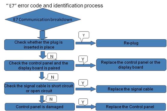
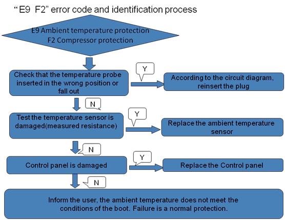
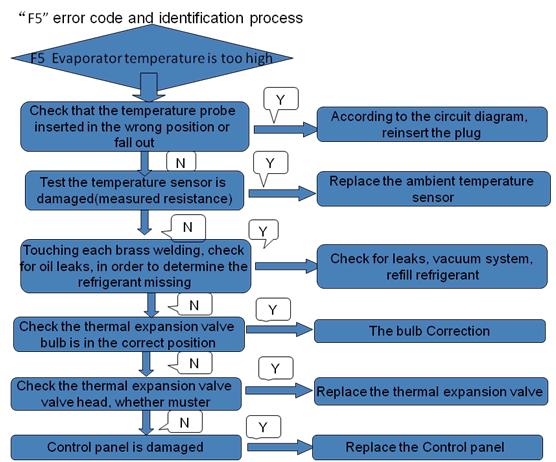
26 8. Faults and protection Fault type Compressor protection Compressor over-current protection Electricity leakage alarming Operating temperature protection Air exhaust temperature protection Evaporation high temperature protection Evaporation low temperature protection Over-current protection The system will automatically cut off power supply if any line fault occurs Over temperature alarming The actual water temperature 85 Fault of the inner temperature sensor Fault of the ambient temperature sensor Fault of the evaporation 1 temperature sensor Fault of the air exhaust temperature sensor Fault of the evaporation 2 temperature sensor If short circuit or circuit break occurs to the sensor If short circuit or circuit break occurs to the sensor If short circuit or circuit break occurs to the sensor If short circuit or circuit break occurs to the sensor If short circuit or circuit break occurs to the sensor Communication of main control panel Communication fault and display panel is abnormal Pressure switch protection Action of the pressure switch at the exhaust outlet Ambient temperature protection Fault of the Solar or boiler temperature sensor Fault of the Off-peak power switching signal Action Ambient or outdoor temperature <-7 or>37 If short circuit or circuit break occurs to the sensor for HP250CM2 If not received the Off-peak signal when selecting switch signals by power companies Digital indication F2 F3 F5 F7 F6 E1 E2 E3 E4 E5 E6 ED E7 E8 E9 EE EF Whether to start electric heater Automatically start electric heater Three times or more, you need to manually start BOOST Can't start electric heater Need to manually start BOOST Can't start electric heater Automatically start electric heater Need to manually start BOOST 26


27 Fault code identification method Operating conditionswhen leakage current 15mA, the system cut off the power supply, display "E1". Leakage current 7.5mA, not action. Operating conditionsthe actual water temperature 85 ; 27

28 28

29 29

30 30
31 Temperature sensor resistance measurement method Temperature sensor resistancee measurement method (method of measuring the resistance value of the compressor of the same, but is switched to the smalll resistance of the interface unit). Multimeter set to Ohms, according to the picture of the method of measuring the resistance of the temperature sensor. According to the resistance table, the lower the temperature the smaller the resistance. Check the thermal expansion valve head is swelling Using calipers to measure is greater than 7.12mm, (example picture for 8.08mm) 31


32 Check the compressor line is through the current transformer Check the signal cable is short-circuited Press the yellow button to switch to the picture, when a short circuit, there is a beep, 32


33 the resistance is zero. Check the tank heater for leaks Press the yellow button to switch to the picture shown, turn the heating power measurements, if leakage resistance is zero, if not leak, show resistance. Check that the power cord L, N lines are in the same order into the leakage protection coil 9. The method of dismantling products Make sure the power cord is disconnected. 1 Remove the Display 33
34 Use a screwdriver to remove the two screws 2 Remove the Cover Use a screwdriverr to remove the screws 3 Remove the Air channel and fan 2. remove the fan 1. remove the Air channel -up 3. remove the Air channel down 4 Remove the Magnesium rod Off the power and close the inlet valve, open any outlett valve, exhaust pressure, when no water flows out of timeturn off alll the valves. Remove the magnesium rod cover 34
35 After removee the magnesium rod, according to the consumptionn of magnesium rod, determine whether you need to replace. magnesium rod cover magnesium rod 5 Remove the temperaturee sensor Removee the fixing screws, remove the water tank flange cover Removee the temperature sensors and thermostat temperature sensor. water tank flange cover Temperature tubeup Temperature tubedown First insert the temperature sensor, and then insert the thermostatt temperature sensor. Temperature sensor must be inserted into the bottom of the tube. 6 Open the control box Use a screwdriver to remove the 4 screws 35
36 Controller panel Ambient temperature sensoryellow Exhaust temperature sensorwhite Evaporator sensor 1red Evaporator sensor 2grey Tank temperature sensorred Solar or boiler sensor Leakage protection coil Municipal low switching signal power Display panel 36
37 7 Remove Electric heater Remove Front cover - down After the Cover is removed, use a screwdriver to remove the bottom two screwss of the Front cover down. Remove Electrical cover Use a screwdriver to remove the 2 screws Remove the internal wiring and electric heater Use a screwdriver to removee the 6 screws. After the tank has been emptied, with a socket wrench to remove the electric heater. 37

38 10. Repairs common tools Tools Name Quantity Illustration Spanner 2pc Hexagon Spanner 1pc Flathead screwdriver 1pc Phillips screwdriver 1pc Needle-nose pliers 1pc Measuring tape 1pc Pressure gauge 1pc Vacuum pump 1pc Electronic scale 1pc Bending device 1pc 38
39 Appendix 1Temperature and resistance table of the Sensor Temperature Tand resistancertableambient temperature T R(KΩ) T R(KΩ) T R(KΩ) T R(KΩ) Temperature Tand resistancertable Exhaust temperatureevaporator temperature T R(KΩ) T R(KΩ) T R(KΩ) T R(KΩ)
40 Temperature Tand resistancertablewater temperature T R(KΩ) T R(KΩ) T R(KΩ) T R(KΩ)
USER MANUAL SILENT16 PORTABLE AIR CONDITIONER
 USER MANUAL SILENT16 PORTABLE AIR CONDITIONER Thank you for choosing electriq Please read this user manual before using this innovative Air Conditioner and keep it safe for future reference. Visit our
DUCTED AIR CONDITIONER. Owner s Manual. KD Series KD24. Kaden Owner s Manual 1
 DUCTED AIR CONDITIONER Owner s Manual KD Series KD24 Kaden Owner s Manual 1 Table of Contents 1. Safety Precautions 4 2. Indoor Unit Parts and Major Functions 6 3. Care and Maintenance 8 4. Troubleshooting
CLIM9000CE PORTABLE AIR CONDITIONER USER MANUAL
 CLIM9000CE PORTABLE AIR CONDITIONER USER MANUAL Please read this user manual before using this innovative Air Conditioner and keep it safe for future reference. SAFETY INSTRUCTIONS Important! Carefully
SILENT 12 PORTABLE AIR CONDITIONER USER MANUAL
 SILENT 12 PORTABLE AIR CONDITIONER USER MANUAL Thank you for choosing ElectriQ Please read this user manual before using this innovative Air Conditioner and keep it safe for future reference. Visit our
USER MANUAL SILENT12 PORTABLE AIR CONDITIONER
 USER MANUAL SILENT12 PORTABLE AIR CONDITIONER Thank you for choosing electriq Please read this user manual before using this innovative Air Conditioner and keep it safe for future reference. Visit our
COMPACT PORTABLE AIR CONDITIONER USER MANUAL
 COMPACT PORTABLE AIR CONDITIONER USER MANUAL Thank you for choosing ElectriQ Please read this user manual before using this innovative Air Conditioner and keep it safe for future reference. Visit our page
Portable Air Conditioner USER MANUAL
 AC12 AC12HP Portable Air Conditioner USER MANUAL Thank you for choosing this innovative Amcor air conditioner. We suggest that you keep this manual in a safe place for future reference. It describes the
INSTALLATION MANUAL. Split-type Air Conditioner (Cooling and Heating) Outdoor Unit UQB09JJWC UQB12JJWC. Indoor Unit AQB09JJWC AQB12JJWC
 Outdoor Unit UQB09JJWC UQB12JJWC. Indoor Unit AQB09JJWC AQB12JJWC") AQB09JJ6WC_IM_E_2585 2006.4.17 4:26 PM Page 17 INSTALLATION MANUAL Indoor Unit AQB09JJWC AQB12JJWC Outdoor Unit UQB09JJWC UQB12JJWC ENGLISH FRANÇAIS ESPAÑOL Split-type Air Conditioner (Cooling and Heating)
AQB09JJ6WC_IM_E_2585 2006.4.17 4:26 PM Page 17 INSTALLATION MANUAL Indoor Unit AQB09JJWC AQB12JJWC Outdoor Unit UQB09JJWC UQB12JJWC ENGLISH FRANÇAIS ESPAÑOL Split-type Air Conditioner (Cooling and Heating)
INSTALLATION MANUAL. Split-type Air Conditioner (Cooling and Heating) Indoor Unit AQB18J6WC AQB24J2WC. Outdoor Unit UQB18J6WC UQB24J2WC
 Indoor Unit AQB18J6WC AQB24J2WC. Outdoor Unit UQB18J6WC UQB24J2WC") AQB8J6WC_IM_E_25864 2006.4.4 3:29 PM Page 7 INSTALLATION MANUAL Indoor Unit AQB8J6WC AQB24J2WC Outdoor Unit UQB8J6WC UQB24J2WC ENGLISH FRANÇAIS ESPAÑOL Split-type Air Conditioner (Cooling and Heating)
AQB8J6WC_IM_E_25864 2006.4.4 3:29 PM Page 7 INSTALLATION MANUAL Indoor Unit AQB8J6WC AQB24J2WC Outdoor Unit UQB8J6WC UQB24J2WC ENGLISH FRANÇAIS ESPAÑOL Split-type Air Conditioner (Cooling and Heating)
THROUGH-WALL AIR-TO-AIR HEAT PUMP AND AIR CONDITIONER. Instruction Manual. Model AMB-12H
 THROUGH-WALL AIR-TO-AIR HEAT PUMP AND AIR CONDITIONER Instruction Manual Model AMB-12H PLEASE READ THIS INSTRUCTION MANUAL CAREFULLY BEFORE USING THIS UNIT. Table of Contents 1. SAFETY WARNINGS 2 2. CONSTRUCTION...
INSTALLATION AND USER MANUAL
 INSTALLATION AND USER MANUAL Thank you for choosing our product and trusting our company. This manual is to provide you with necessary information for optimal use and maintenance, please read carefully
INSTALLATION AND USER MANUAL
 INSTALLATION AND USER MANUAL t Thank you for choosing Aqua inverter heat pump. This manual provides you necessary information for optimal use and maintenance, please read it carefully and keep it for subsequent
Owner s Manual. Middle Static Pressure Duct Type MEU-18MPH2 MEU-24MPH2 MEU-36MPL2 MEU-48MPL2 MIDDLE STATIC PRESSURE DUCT TYPE AIR CONDITIONER
 MIDDLE STATIC PRESSURE DUCT TYPE AIR CONDITIONER Owner s Manual Middle Static Pressure Duct Type MEU-18MPH2 MEU-24MPH2 MEU-36MPL2 MEU-48MPL2 IMPORTANT NOTE: Read this manual carefully before installing
Air to Water Heat Pump -Mono Control Unit. user manual. imagine the possibilities
 Control Unit RC120MHXGA RC140MHXGA RC160MHXGA RC090MHXEA RC120MHXEA RC140MHXEA RC160MHXEA Air to Water Heat Pump -Mono Control Unit user manual imagine the possibilities Thank you for purchasing this Samsung
15,000 BTU Portable Air Conditioner
 Instruction Manual 15,000 BTU Portable Air Conditioner Model: HYAC15 READ AND SAVE THESE INSTRUCTIONS Please read and follow the instructions in this user manual even if you feel you are familiar with
INSTALLATION AND USER MANUAL
 INSTALLATION AND USER MANUAL Thank you for choosing inverter heat pump. This manual provides you necessary information for optimal use and maintenance, please read it carefully and keep it for subsequent
PORTABLE AIR CONDITIONER
 PORTABLE AIR CONDITIONER Model: PEL00460 1 CONTENTS Page No. Details 2 Important Safety Information 3 Product Overview 3 Positioning & Installation 4 Installation Errors 4 Control Panel 5 Screen IMPORTANT
51AKS I S O OWNER S MANUAL
 LLOYD'S REGISTER QUALITY ASSURANCE 51AKS I S O 9 00 1 OWNER S MANUAL This manual applies to the following models Stand-alone Split 51AKS 085--- 51AKS 010--- 51AKS 185--- 51AKS 013--- 51AKS 113--- 51AKS
Instruction Manual Refrigerator-freezer
 Instruction Manual Refrigerator-freezer MODEL:EFD635SX Please read carefully before using our products. Please keep this operation instruction properly for future reference. INFORMATION ON ENVIRONMENT
Aqua 1 plus Air-water heat pumps for domestic hot water production
 Aqua 1 plus Air-water heat pumps for domestic hot water production THE FLEXIBLE EFFICIENCY is a range of heap pumps for domestic hot water production, fit for small residential applications. It is the
INSTALLATION INSTRUCTIONS POINT OF USE WATER HEATERS EPU - US10 EPU - US15
 INSTALLATION INSTRUCTIONS POINT OF USE WATER HEATERS EPU - US10 EPU - US15 01 CONTENTS Special information 2 General information 3 Safety 5 Appliance description, cleaning, care & maintenance 7 Appliance
Swimming Pool Heat Pump
 Swimming Pool Heat Pump Operation and Installation Manual MODEL FH-020 CONTENTS INTRODUCTION Index............ 2 The unit...... 2 SAFETY INSTRUCTIONS... 4 Electrical Installation Warning.. 4 Location Warning
Installation Manual. Instrucciones de instalación y manual de usuario 1
 Installation Manual Instrucciones de instalación y manual de usuario 1 Installation instructions and user manual V8 2 INDEX 1 GENERAL SAFETY WARNINGS... 4 2 OPERATING PRINCIPLE... 5 3 TECHNICAL FEATURES...
Installation, Service and User Manual DTW 300 SP
 Installation, Service and User Manual DTW 300 SP VMGFK202 If these instructions are not followed during installation and service, Danfoss A/S liability according to the applicable warranty is not binding.
OPERATING INSTRUCTIONS
 EN DEHUMIDIFIER LILIUM 11 LILIUM 13 OPERATING INSTRUCTIONS Read the instructions carefully before operating or servicing the dehumidifier. Observe all the safety instructions; failure to observe the instructions
User Manual. Vanvex Optima 180 Domestic Hot Water. Version
 GB User Manual Vanvex Optima 180 Domestic Hot Water Version 3.07-0310 Table of contents Page 1. Users Guide 1.1 Use... 3 1.2 Altering of the operation data... 3 1.3 Operating menu... 4 1.4 Factory default
InverterFlex Series Multi-Zone Ducted Indoor Unit B-VFH09DA-1 B-VFH12DA-1 B-VFH18DA-1 B-VFH24DA-1
 INSTALLATION, OPERATION & MAINTENANCE MANUAL InverterFlex Series Multi-Zone Ducted Indoor Unit B-VFH09DA-1 B-VFH12DA-1 B-VFH18DA-1 B-VFH24DA-1 Heat Controller 1900 Wellworth Ave. Jackson, MI 49203 (517)787-2100
1.6kW Window / Wall Air Conditioner
 1.6kW Window / Wall Air Conditioner INSTRUCTION MANUAL Model EUR-5000WAC AFTER SALES SUPPORT (AU) 1300 886 649 (NZ) 0800 836 761 E209 Contents Page Important Safety Instructions 3 Product Overview 6 Getting
OPERATING INSTRUCTIONS
 EN DEHUMIDIFIER OPERATING INSTRUCTIONS Read the instructions carefully before operating or servicing the dehumidifier. Observe all the safety instructions; failure to observe the instructions may lead
INSTALLATION INSTRUCTIONS & HOME OWNERS MANUAL AUTOBOOSTER IMPORTANT SAFETY INFORMATION
 INSTALLATION INSTRUCTIONS & HOME OWNERS MANUAL AUTOBOOSTER IMPORTANT SAFETY INFORMATION When installing or using any high voltage electrical appliance, basic safety precautions should always be followed.
PRODUCT DATA COMPACT P - SERIES BY NILAN. Sanitary hot water production. Heating. Ventilation < 300 m 3 /h. Passive heat recovery.
 PRODUCT DATA COMPACT P - SERIES BY NILAN Domestic Passive heat recovery Active heat recovery Ventilation < 300 m 3 /h Comfort heating Comfort cooling Sanitary hot water production Heating THE VENTILATION
SELF-PRIMING JET PUMPS
 SS Anti-Rust SS Shaft Copper & Cold-rolled SELF-PRIMING JET PUMPS CONTENTS 1. Applications.... Model Description.... Technical Data... 4. Implementation Standards... 5. Safety Precautions... 6. Product
Manual is for the following models: G-26 GCG-26 GCG-26-C31N* G-26-C31N* GCG-26-C231N* GCG-26-CA31N* *G,I,M,7,J plug. Instruction Manual.
 G-Series Cooler G-26c/GCG-26c UPRIGHT COOLER Manual is for the following models: G-26 GCG-26 GCG-26-C31N* G-26-C31N* GCG-26-C231N* GCG-26-CA31N* *G,I,M,7,J plug Instruction Manual Manual is for the following
GCG-10. Instruction Manual. G-Series Cooler. Manual is for the following models: GCG-10-N33EB G-10-N33EB UPRIGHT COOLER
 G-Series Cooler GCG-10 UPRIGHT COOLER Manual is for the following models: GCG-10-N33EB G-10-N33EB Instruction Manual Manual is for the following models: GCG-10-N33EB G-10-N33EB Instruction Manual GCG-10
User instructions DHP-AT
 User instructions DHP-AT VUGFC202 If these instructions are not followed during installation and service, Danfoss A/S liability according to the applicable warranty is not binding. Danfoss A/S retains
Inverter Air Source Heat Pump Monobloc system
 Inverter Air Source Heat Pump Monobloc system Product Data & Installation Manual AXAI-06M & AXAI-09M AXAI-12M & AXAI-15M TABLE OF CONTENT INSTRUCTIONS 1 This manual 1 Items inside product box. 2 Tools
PORTABLE AIR-CONDITIONER MODEL: EPAC-A4010D(WH) Owner s Manual Please read this manual carefully before operating your set.
 Owner s Manual Please read this manual carefully before operating your set.") PORTABLE AIR-CONDITIONER MODEL: EPAC-A4010D(WH) Owner s Manual Please read this manual carefully before operating your set. Retain it for future reference. Record model number and serial number of the
PORTABLE AIR-CONDITIONER MODEL: EPAC-A4010D(WH) Owner s Manual Please read this manual carefully before operating your set. Retain it for future reference. Record model number and serial number of the
Owner s Manual AIR TO WATER HEAT PUMP. Hydro Unit HWS-804XWHM3-E HWS-804XWHT6-E HWS-804XWHT9-E HWS-1404XWHM3-E HWS-1404XWHT6-E HWS-1404XWHT9-E
 AIR TO WATER HEAT PUMP Hydro Unit Model name: HWS-804XWHM3-E HWS-804XWHT6-E HWS-804XWHT9-E HWS-1404XWHM3-E HWS-1404XWHT6-E HWS-1404XWHT9-E English Thank you very much for purchasing TOSHIBA Air to Water
Owner s Manual Super-Slim Four-Way Cassette
 CASSETTE- TYPE AIR CONDITIONER Owner s Manual Super-Slim Four-Way Cassette IMPORTANT NOTE: Read this manual carefully before installing or operating your new air conditioning unit. Make sure to save this
Service Manual & Installation Manual
 GE Consumer & Industrial Appliances Service Manual & Installation Manual Split System Air Conditioner Model numbers: GE AIR F24 GE AIR F34 GE AIR F41 1 2 3 Introduction and Features Model Remarks GE AIR
Bar Fridge USER MANUAL MB46W
 Bar Fridge USER MANUAL MB46W CONTENTS Safety information... 2-3 Identifying parts of the fridge... 4 Transporting... 5 Installation... 5 Reversing the door... 6 Operating instructions... 7 Cleaning &
user manual Dishwasher ESL 46510
 user manual Dishwasher ESL 46510 2 electrolux CONTENTS Electrolux. Thinking of you. Share more of our thinking at www.electrolux.com Safety information 2 Product description 5 Control panel 5 Use of the
G-7s. Instruction Manual. G-Series Cooler COUNTERTOP COOLER. Part No.11IPA
 G-Series Cooler COUNTERTOP COOLER Part No.11IPA-061000 Instruction Manual FOR YOUR FUTURE REFERENCE This easy-to-use manual will guide you in getting the best use of your cooler. Remember to record the
TOSHIBA AIR CONDITIONING
 Introduction The following specification describes the Toshiba Estia Air to Water Heat Pump system(s) to be installed at the site below: (ADD SITE NAME) The system(s) shall consist of the following components.
PORTABLE AIR CONDITIONER (LOCAL)
") EN PORTABLE AIR CONDITIONER (LOCAL) OPERATING INSTRUCTIONS Read the instructions carefully before operating the appliance or carrying out maintenance work. Observe all the safety instructions; failure
EN PORTABLE AIR CONDITIONER (LOCAL) OPERATING INSTRUCTIONS Read the instructions carefully before operating the appliance or carrying out maintenance work. Observe all the safety instructions; failure
GCG-9. Instruction Manual. G-Series Cooler. Manual is for the following models: GCG-9-N13EB G-9-N13EB GCG-9-B13EB UPRIGHT COOLER
 G-Series Cooler UPRIGHT COOLER Manual is for the following models: -N13EB G-9-N13EB -B13EB Instruction Manual FOR YOUR FUTURE REFERENCE This easy-to-use manual will guide you in getting the best use of
PORTABLE AIR CONDITIONER (LOCAL)
") EN PORTABLE AIR CONDITIONER (LOCAL) OPERATING INSTRUCTIONS Read the instructions carefully before operating the appliance or carrying out maintenance work. Observe all the safety instructions; failure
EN PORTABLE AIR CONDITIONER (LOCAL) OPERATING INSTRUCTIONS Read the instructions carefully before operating the appliance or carrying out maintenance work. Observe all the safety instructions; failure
Owner s Manual INVERTER ONE-TWO/ONE-THREE /ONE-FOUR/ONE-FIVE SPLIT-TYPE AIR CONDITIONER
 INVERTER ONE-TWO/ONE-THREE /ONE-FOUR/ONE-FIVE SPLIT-TYPE AIR CONDITIONER Owner s Manual IMPORTANT NOTE: Read this manual carefully before installing or operating your new air conditioning unit. Make sure
PORTABLE AIR CONDITIONER
 PORTABLE AIR CONDITIONER Model: PEL00461 1 CONTENTS Page No. Details 3 Important Safety Information 4 Introduction 4 Positioning 4 Installation 5 Control Panel 6 Remote Control 6 Operation Modes 7 Water
Refrigerator KE T
 Refrigerator KE 680-1-3T Service Manual: H8-74-07 Responsible: U. Laarmann KÜPPERSBUSCH HAUSGERÄTE AG E-mail: uwe.laarmann@kueppersbusch.de Tel.: (0209) 401-732 Customer Service Fax: (0209) 401-743 Postfach
Hot Water Circulator Pump LRP
 Hot Water Circulator Pump LRP Contents. Introduction.... Safety Instruction... 3.Product Structure... 4 4. Technical Parameters... 7 5. Precautions... 8 9. Troubleshooting Disconnect power supply before
Double Door - Dual Zone Wine Cooler
 THE PERFECT BALANCE OF FUNCTION, STYLE AND RELIABILITY LAUNDRY - DISHWASHING - COOKING - COOLING Installation and Operating Manual Double Door - Dual Zone Wine Cooler WS38SDDX Stainless Steel Please read
INVERTER ONE-TWO/ONE-THREE/ONE-FOUR/ONE-FIVE SPLIT-TYPE AIR CONDITIONER
 INVERTER ONE-TWO/ONE-THREE/ONE-FOUR/ONE-FIVE SPLIT-TYPE AIR CONDITIONER Owner s Manual Model: 3554190/3554191/3554192/3554193 3554194/3554195/3554196/3554197 IMPORTANT NOTE: Read this manual carefully
Owner s Manual INVERTER ONE-TWO/ONE-THREE /ONE-FOUR/ONE-FIVE SPLIT-TYPE AIR CONDITIONER
 INVERTER ONE-TWO/ONE-THREE /ONE-FOUR/ONE-FIVE SPLIT-TYPE AIR CONDITIONER Owner s Manual IMPORTANT NOTE: Read this manual carefully before installing or operating your new air conditioning unit. Make sure
DUCT COOLERS KWK KFK OPERATION MANUAL. KWK_KFK_v2(4)_EN.indd :35:29
_EN.indd :35:29") DUCT COOLERS KWK KFK EN OPERATION MANUAL KWK_KFK_v2(4)_EN.indd 1 13.06.2016 13:35:29 CONTENTS 3 Introduction 3 General 3 Safety rules 3 Transportation and storage regulations 3 Manufacturer s warranty
DUCT COOLERS KWK KFK EN OPERATION MANUAL KWK_KFK_v2(4)_EN.indd 1 13.06.2016 13:35:29 CONTENTS 3 Introduction 3 General 3 Safety rules 3 Transportation and storage regulations 3 Manufacturer s warranty
CONTENTS 1 SAFETY INSTRUCTIONS.. 2 FEATURES AND OPERATION... 3 PARTS LIST AND INSTALLATION. 4 CONTROL PANEL AND SETTINGS...
 AC100-R CONTENTS 1 SAFETY INSTRUCTIONS.. 2 2 FEATURES AND OPERATION.... 3 3 PARTS LIST AND INSTALLATION. 4 4 CONTROL PANEL AND SETTINGS... 5 6 MAINTENANCE 6 7 TROUBLE SHOOTING.. 7 8 APPENDIX. 8 1 SAFETY
PHRT HEAT PUMP WITH HYDRAULIC EQUIPMENT AIR / WATER 9 to 18 KW
 TECHNICAL INSTRUCTIONS PHRT HEAT PUMP WITH HYDRAULIC EQUIPMENT AIR / WATER to KW PHRT PHRT PHRT PHRT For terminal units and boiler overhaul applications Heating Cooling PHRT.00 kw -. kw PHRT.0 kw /.0 kw
Portable Air-conditioner
 Use and Care Manual Portable Air-conditioner Thank you very much for selecting this new model of Portable Air Conditioner, please read this Use and Care Manual carefully before installing and using this
KSD-35 DR11 KUE-35 DVN11
 FLOOR-STANDING TYPE AIR CONDITIONER Owner s Manual Floor-Standing Type KSD-35 DR11 KUE-35 DVN11 IMPORTANT NOTE: Read this manual carefully before installing or operating your new air conditioning unit.
DOMESTIC HOT WATER HEAT PUMP 08: Manual METROAIR AQUA 201 METROAIR AQUA 301 S
 DOMESTIC HOT WATER HEAT PUMP 08:956-1806 Manual METROAIR AQUA 201 METROAIR AQUA 301 S 1 2 TABLE OF CONTENTS Introduction... 4 1. About the product.... 4 2. Transport, Handling and Delivery....13 3. Positioning...15
CZT CZT. High efficiency air to water heat pumps with E.V.I. compressors E.V.I. HP OTHER VERSIONS ACCESSORIES
 High efficiency air to water heat pumps with E.V.I. compressors infolinia: +48 691 262 691-15 C +63 C +43 C E.V.I. HP The series of high efficiency heat pumps has been specifically designed for use with
Technical Manual Binair Monobloc Heat Pump
 Technical Manual Binair Monobloc Heat Pump MODEL BINAIR12 Introduction Disassembly of the machine must be carried out by any professional or any special agency assigned by us. All operation and maintenance
OWNER S MANUAL KPD-105 DTN11 KPD-140 DVN11 KPD-140 DTN11 KPD-160 DTN11 KPD-52 DVR11
 OWNER S MANUAL A6 Duct KPD-35 DVN11 KPD-52 DVN11 KPD-71 DVN11 KPD-90 DVN11 KPD-105 DVN11 KPD-105 DTN11 KPD-140 DVN11 KPD-140 DTN11 KPD-160 DTN11 KPD-52 DVR11 KPD-71 DVR11 KPD-105 DVR11 KPD-105 DTR11 KPD-140
Dehumidifier User Manual. (For the series of DP40~DP70)
") Dehumidifier User Manual (For the series of DP40~DP70) Content I. Please read immediately... 1 II. Application... 2 III. Features... 2 IV. Technical Parameters... 3 V. Overall Dimension... 4 VI. Installation
Dehumidifier User Manual (For the series of DP40~DP70) Content I. Please read immediately... 1 II. Application... 2 III. Features... 2 IV. Technical Parameters... 3 V. Overall Dimension... 4 VI. Installation
PORTABLE AIR CONDITIONER (LOCAL)
") EN PORTABLE AIR CONDITIONER (LOCAL) OPERATING INSTRUCTIONS Read the instructions carefully before operating the appliance or carrying out maintenance work. Observe all the safety instructions; failure
EN PORTABLE AIR CONDITIONER (LOCAL) OPERATING INSTRUCTIONS Read the instructions carefully before operating the appliance or carrying out maintenance work. Observe all the safety instructions; failure
Warning: 230V / 1ph / 50Hz V / 3ph / 50Hz. Remarks: Make sure that you have enough power. (See page 15 Cable table)
") 1 2 Warning: - Do not place your hand or any other objects into the air outlet and fan. It could damage the heat pump and cause injuries; - In case of any abnormality with the heat pump, cut off the power
1 2 Warning: - Do not place your hand or any other objects into the air outlet and fan. It could damage the heat pump and cause injuries; - In case of any abnormality with the heat pump, cut off the power
HP WH SERIES HEAT PUMP WATER HEATER. 200l 300l HP200M1, HP250M1 / HP200M3, HP250M3, HP250M3C / HP200S1, HP300S1
 HP WH SERIES HEAT PUMP WATER HEATER 200l 300l HP200M1, HP250M1 / HP200M3, HP250M3, HP250M3C / HP200S1, HP300S1 MAIN ADVANTAGES Plug & play, easy to install Trendsetting Low upfront costs will deliver energy
INSTALLATION AND USER MANUAL
 Swimming Pool Heat Pump Swimming Pool Heat Pump INSTALLATION AND USER MANUAL Thank you for choosing our product and trusting our company. This manual is to provide you with necessary information for optimal
GCG-26c. Instruction Manual. G-Series Cooler
 G-Series Cooler UPRIGHT COOLER Manual is for the following models: GCG-26-C14N7 GCG-26-C14NG GCG-26-C14NI GCG-26-C14NM GCG-26-C14NJ GCG-26 G-26-C14N7 G-26-C14NG G-26-C14NI G-26-C14NM G-26-C14NJ G-26 Instruction
INSTALLATION MANUAL. Domestic hot water tank for air to water heat pump system EKHWE150A3V3 EKHWET150A3V3 EKHWE200A3V3 EKHWE300A3V3
 INSTALLATION MANUAL Domestic hot water tank for air to water heat pump system EKHWE50AV EKHWET50AV EKHWE00AV EKHWE00AV EKHWE00AZ EKHWE00AZ 4 5 6 7 x x x 4x x x x EKHWE50~00 EKHWET50 50 50 0 0 00 50 700
GeyserWise MAX. Instruction manual. All in one hot water management
 GeyserWise MAX All in one hot water management Before operating and installation, carefully read all instructions. Do not discard this manual. DISPLAY The display is the feedback mechanism to the user
Koolbreeze. Portable Air-conditioner User s Manual. For Model : CLIMATEASY 14 P14HCP. Downloaded from manuals search engine
 Koolbreeze Portable Air-conditioner User s Manual For Model : CLIMATEASY 14 P14HCP Table of Contents 1. Installation.. 2 2. General Safety Reqirements.. 4 3. Product safety.... 5 4. Safety Awareness....
SPECIFICATION GUIDE FLEXAIR. Possibility to add auxiliary heaters: Gas, Electrical Heater, Hot Water Coil Possibility to add Heat Recovery Module
 SPECIFICATION GUIDE FLEXAIR Air-cooled packaged Rooftop unit Cooling only or Heat Pump Nominal cooling capacity: 85 to 234 kw Nominal heating capacity: 83 to 226 kw Possibility to add auxiliary heaters:
CHEST FREEZER HS225523
 CHEST FREEZER HS225523 WARNING! In order to ensure a normal operation of your refrigerating appliance, which uses a completely environmentally friendly refrigerant the R600a (flammable only under certain
Room Air Conditioner Service and Parts Manual
 Cool Dry Temp Mode Room Air Conditioner Service and Parts Manual F Fan Speed hr Timer 0n 0ff Money Saver Fan Only Auto Swing Power CP06 CP08 93011401_01 CONTENTS 1. PREFACE 1.1 SAFETY PRECAUTIONS...2 1.2
ARTICA. 8000Btu. Room Air Conditioners Portable Range
 UK ARTICA 8000Btu Room Air Conditioners Portable Range INDEX Congratulations! You have purchased the very latest in room air conditioning technology. Your new EcoAir high efficiency room appliance will
Heat Pump Water Heater. Table of Contents
 Table of Contents INTRODUCTION... 3 SAFETY... 3 Electrical... 3 R410a Refrigerant... 3 Scalding... 3 Flammable Vapors... 3 COMPONENT PARTS OF THE HEAT PUMP WATER HEATER... 4 TOOLS... 10 OPERATIONAL MODES...
Installer manual AG-AA10. Air/air heat pump IHB GB AG-AA10-30 AG-AA10-40/50
 -30 Installer manual Air/air heat pump -40/50 IHB GB 1516-1 331554 Table of Contents 1 Important information 2 5 Installation 7 Safety information 2 Model combinations 7 Read before starting the installation
PHRIE / PHIE InvERTER monoblock air To water HEaT PumP medium TEmPERaTuRE
 TEcHnIcal InsTRucTIons PHRIE / PHIE InvERTER monoblock air To water HEaT PumP medium TEmPERaTuRE PHRIE 095 PHRIE 1 PHIE 095 PHIE 1 PHRIE 155 PHRIE 157 PHRIE 175 PHRIE 177 PHRIE 195 PHRIE 197 PHRIE 7 PHRIE
ENVIRONMENTAL CONTROL UNIT (ECU) PART NUMBER OPERATIONS AND MAINTENANCE MANUAL
 PART NUMBER OPERATIONS AND MAINTENANCE MANUAL") ENVIRONMENTAL CONTROL UNIT (ECU) PART NUMBER 2001829 OPERATIONS AND MAINTENANCE MANUAL Prepared by: 860 Douglas Way PO Box 530 Natural Bridge Station, VA 24579 1.0 SCOPE: This Operations and Maintenance
ENVIRONMENTAL CONTROL UNIT (ECU) PART NUMBER 2001829 OPERATIONS AND MAINTENANCE MANUAL Prepared by: 860 Douglas Way PO Box 530 Natural Bridge Station, VA 24579 1.0 SCOPE: This Operations and Maintenance
Inverter Swimming Pool Heat Pump
 P Inverter Swimming Pool Heat Pump Content I. Application... 2 II. Features... 2 III. Technical Parameter... 3 IV. Dimension... 4 V. Installation instruction... 5 VI. Operation instruction... 9 VII. Testing...
PDA20DX Air Purifying Dehumdifier Manual
 PDA20DX Air Purifying Dehumdifier Manual Index Important Safe Guards Ambient Environment For Operating Components Diagrams---Parts Names Operating Introduction---How to operate - Functions of Control Panel
10L Dehumidifier. Model Number: LDH V AC 50/60Hz 290W
 10L Dehumidifier Model Number: LDH1001 220-240V AC 50/60Hz 290W For Customer Services & Spare Parts please call 0345 209 7461 Opening times: Monday - Friday 8am 8pm & Saturday 9am 1pm Or visit us at www.productcare.co.uk
USER S MANUAL HSC-14/18/24/24A
 AIRREX AIR CONDITIONER USER S MANUAL HSC-14/18/24/24A Thank you for purchasing an AIRREX AIR CONDITIONER. BEFORE operation please read this user s manual carefully. Keep this manual readily available.
LZT High efficiency air to water heat pumps with E.V.I. compressors
 High efficiency air to water heat pumps with E.V.I. compressors -20 C +43 C +65 C E.V.I. C.O.P. 4,1 The series of high efficiency heat pumps has been specifically designed for use with radiant floor heating
20L Dehumidifier. Model Number: LDH V AC 50/60Hz 440W
 20L Dehumidifier Model Number: LDH2002 220-240V AC 50/60Hz 440W For Customer Services & Spare Parts please call 0345 209 7461 Opening times: Monday - Friday 8am 8pm & Saturday 9am 1pm Or visit us at www.productcare.co.uk
METAL CERAMIC FAN HEATER
 EN METAL CERAMIC FAN HEATER OPERATING INSTRUCTIONS Read the instructions carefully before installing and operating the appliance or performing maintenance operations. Observe all the safety instructions;
EXPLORER HEAT PUMP WATER HEATER. A+ in READY Smart heat pump
 HEAT PUMP WATER HEATER EXPLORER 7% energy savings * Wide temperature range of use (- to + C) ACI hybrid anti-corrosion protection Smart energy consumption control Remote piloting with Cozytouch technology
Part 5. Troubleshooting. 1. Normal Air Conditioner Phenomenon Air Conditioner Protection in Common
 Part 5 1. Normal Air Conditioner Phenomenon... 1611 2. Air Conditioner Protection in Common... 1611 3. Malfunction Code and... 162 160 1. Normal Air Conditioner Phenomenon 1.1 When outdoor unit appears
Air-to-Water Heatpump
 Order No. PHAAM1006120C2 Air-to-Water Heatpump Indoor Unit Outdoor Unit WH-SDC07C3E5 WH-UD07CE5-A WH-SDC09C3E5 WH-UD09CE5-A WH-SDC12C6E5 WH-UD12CE5-A WH-SDC14C6E5 WH-UD14CE5-A WH-SDC16C6E5 WH-UD16CE5-A
LOCAL AIR CONDITIONER
 EN LOCAL AIR CONDITIONER OPERATING INSTRUCTIONS Read the instructions carefully before operating the appliance or carrying out maintenance work. Observe all the safety instructions; failure to observe
- 1 - Updated on 18 March, 2010
 - 1 - Updated on 18 March, 2010 TABLE OF CONTENTS 1. SPECIFICATION & PARTS IDENTIFICATION...3 2. OPERATION & FUNCTION OF PARTS...4, 5 A. Cooling Operation B. Heating Operation C. Function of Parts 3. LOCATION
Reverse Cycle Split System Air Conditioner
 PROTECT YOUR WARRANTY This unit must be installed by a registered, licensed installer as required by Government regulations. Reverse Cycle Split System Air Conditioner USER MANUAL Model Number AK-12000-RC
WINDOW TYPE ROOM AIR CONDITIONER OPERATION AND INSTALLATION MANUAL
 MODEL RA-0LDF RA-3LDF WINDOW TYPE ROOM AIR CONDITIONER OPERATION AND INSTALLATION MANUAL AIR DEFLECTORS VERTICAL DEFLECTORS Vertical de ectors at both sides of outlets can be set to either auto-swing or
G-10f/GCG-10f UPRIGHT COOLER
 G-Series Cooler G-10f/GCG-10f UPRIGHT COOLER Manual is for the following models: G-10F, G-10-F33EB GCG-10F, GCG-10-F33EB GCG-10F2, GCG-10-F233EB G-10-F33EB-HC, GCG-10-F33EB-HC GCG-10-F233EB-HC Instruction
Split Air Conditioner. Model: WMI09MH16S WMI12MH16S WMI18MH16S
 Split Air Conditioner Model: WMI09MH16S WMI12MH16S WMI18MH16S Thank you for choosing our product. For proper operation, please read and keep this manual carefully. Content Operation Notices Precautions...1
HPWH 300 HPWH 300HE. Installation and Operating Instructions. Hot Water Heat Pump for Outdoor Installation. English FD 9501
 HPWH 300 HPWH 300HE Installation and Operating Instructions Hot Water Heat Pump for Outdoor Installation FD 9501 Table of contents 1 Please read immediately... EN-2 1.1 Important notes... EN-2 1.2 Intended
PLEASEREADANDSAVETHESEINSTRUCTIONS. NewAir AC-14000E, AC-14000H Portable Air Conditioner Owner's Manual
 PLEASEREADANDSAVETHESEINSTRUCTIONS NewAir AC-14000E, AC-14000H Portable Air Conditioner Owner's Manual GENERAL SAFETY INSTRUCTIONS: ALWAYS OPERATE THE UNIT IN AN UPRIGHT POSITION AND PLACE IT ON A FLAT,
Portable Room Air Conditioner and Heat Pump
 Installation, Operation & Maintenance Manual Portable Room Air Conditioner and Heat Pump PS-121B PSH-141A Thank you for purchasing our Portable Air Conditioner. French version of this manual is available
Refrigerated Compressed Air Dryer
 Manual Instruction for Refrigerated Compressed Air Dryer Warning: Place the dryer machine horizontal. Never upside down Dino-power Industry & Trade Co., Ltd www.aircompressorschina.com Dino-power 1 PREPARED