Air Preparation System
|
|
|
- Rosalind Bennett
- 5 years ago
- Views:
Transcription
1
2
3 Theory of Operation/Product Description (continued) THEORY OF OPERATION/PRODUCT DESCRIPTION CHAPTER 1 RK2 Systems ozones are designed for safe, effective use in a variety of water treatment applications. The 1000mg and 2500mg ozone generators have been tested and certified by the Water Quality Association according to NSF/ANSI 50. Each complete, integrated system may include the components required for reliable, efficient ozone production and can be divided into four general segments: Air preparation system Ozone generator Ozone injection/contacting Ozone destruct Booster Pump Ozone Injector Water Flow Off Gas Vent Ball Valve Ozone Destruct System Optional Air Preparation Ozone Generator Ozone Destruct Unit Option 1 Water Trap Vacuum Break Contact Vessel Option 2 Air Preparation System Shown: RK2 Systems 1000mg or 2500mg with oxygen (Option 1) and 1000mg/AD or 2500mg/AD with internal air dryer (Option 2) Ozone Systems RK2 Systems corona discharge ozone generators require a source of clean, dry, oil-free, oxygen-enriched or dry air for effective ozone production. To meet that need, RK2 Systems can provide any one of three types of air preparation systems. The first type combines pressure swing adsorption (PSA) oxygen technology with oil-less compressor to increase the concentration of oxygen and reduce the moisture content in the feed gas (the air supplied to the ozone generator). This substantially improves the output capability of the ozone generator and prevents premature failure of key internal components. These air preparation systems deliver 90%+/-3% oxygen purity at -100 F dew point and at very low pneumatic pressures, minimizing noise and reducing compressor wear. The PSA system is rated with a continuous duty cycle in conditions up to 90% relative humidity non-condensing. The second type is low pressure swing adsorption (LPSA) dry air technology which operates in the same way as the PSA oxygen system but only delivers 20% oxygen purity at -60 to -90 F dew point. The LPSA system is rated with a continuous duty cycle in conditions up to 90% relative humidity non-condensing. The third type is a heat regenerative dry air system. The heat regenerative system operates via a vacuum which draws in ambient air and dries it to a -10 to -20 F dew point at 20% oxygen purity. The 1000mg/AD and 2500mg/AD ( AD represents Air Dryer) incorporate a heat regenerative air dryer system, rated with a duty cycle of no more than 10 hours of operation in a 24 hour period in conditions up to 75% relative humidity non-condensing. Due to the operation of the internal air dryer, continuous power must be applied to the 1000mg/AD and 2500mg/AD for proper 2

4 Theory of Operation/Product Description (continued) operation. As the ambient air travels through the dryer chambers the sieve material inside traps the moisture from the air and allows the oxygen to pass to the ozone reaction chamber. The heat, generated by the heating rods inside the dryer chamber, then evaporates the moisture that has been trapped in the sieve and expels off the top of the sieve bed. The two dryer chambers and attached 3-way solenoid valve operate on a timed cycle. Dryer chamber 1 heats first evaporating moisture for 1-1/2 hours, while the solenoid is energized allowing the vacuum from the venturi to draw air flow through dryer chamber 2. During this time the AIR PREP LED will flash and DRYER 1 LED will be illuminated continuously. After the 1-1/2 hours there is a 1/2 hour cool down period, power to dryer chamber 1 will be discontinued, correspondingly DRYER 1 LED will not be illuminated. Note: The AIR PREP LED will remain flashing throughout the cycle. After the cool down period dryer chamber 2 will heat and the solenoid valve will de-energize, allowing vacuum from the venturi to draw air flow through dryer chamber 1. During this time the AIR PREP LED will flash and DRYER 2 LED will be illuminated continuously. After 1-1/2 hours there is a 1/2 hour cool down period when power to dryer chamber 2 will be discontinued; correspondingly, DRYER 2 LED will not be illuminated. After this 1/2 hour cool down, the air dryer cycle will repeat. If Plant Air feed gas is to be used in place of a RK2 Systems air preparation system, the same air quality standards must be met to achieve the ozone output and longevity of the ozone generator. A pounds per square inch (PSI) regulator must be installed when using plant air feed gas. This regulator must be set to a maximum of 5 PSI. The type of air preparation will effect ozone production in grams per hour and, more importantly, ozone concentration - also known as percent by weight. Since ozone is produced with oxygen, the greater the percent of oxygen that enters the ozone generator, producing more grams per hour and concentration of ozone. Since a PSA oxygen concentrator has an oxygen output that is nearly four and a half times greater than a standard air dryer, it will yield the highest grams per hour with the highest concentrations. Greater ozone concentration equates to higher solubility of the ozone gas in solution, which will yield a greater oxidation potential. Ozone Generator The feed gas produced by the either the PSA or LPSA air preparation system is supplied to the RK2 Systems ozone generator at a maximum pressure of 5 pounds per square inch (PSI). Note: If a heat regenerative air dryer is used the feed gas will be at drawn through the ozone generator under vacuum. An external air flow meter and vacuum gauge is recommended to be used to control and monitor the air flow and vacuum through the ozone generator. At this point, the feed gas is drawn through the ozone generator by the vacuum created at the ozone injector rather than by the pressure from the air preparation system compressors. As the feed gas enters the thermally-protected reaction chambers inside the ozone generator, some of the oxygen molecules are split while passing through the high voltage electrical field (the corona ), forming single oxygen atoms (O 1 ). These oxygen atoms then recombine with other oxygen molecules in the air stream, forming ozone. Depending on the application, the RK2 Systems ozone generator may be interlocked with an oxidation reduction potential (ORP) or parts per million (PPM) controller, pressure switch flow switch, timer, or circulation pump. Many safety features are also built in, including main power fuses, thermal protection, cover safety switch, and back flow prevention. Ozone Injection/Contacting The ozone injector serves two purposes. One, it creates the vacuum required to safely draw the ozone gas from the ozone generator and two, it provides a means by which the ozone gas can become dissolved in water. A very dynamic injection process is required to effectively dissolve ozone in water. 3
5 Theory of Operation/Product Description (continued) RK2 Systems injection systems use only Mazzei injectors for maximum mass transfer efficiency. The injector produces a cavitation effect, enabling the ozone gas to join the water stream in the form of extremely tiny bubbles. These bubbles must be as small as possible in order to increase the ratio of bubble surface area to the amount of ozone entering the water. Depending on the application and the water treatment goals, a RK2 Systems contacting system may also be required. Some oxidation reactions take place so quickly that they are limited only by the rate at which the ozone is dissolved in the water. Other reactions, such as disinfection, may require that proper ozone residual be maintained for a specific amount of time. A correctly sized contact vessel is used for this purpose. Ozone Destruct The RK2 Systems off-gas destruct systems consist of two components: the ozone destruct unit (a heated chamber filled with manganese dioxide and copper oxide) and a water trap. Used in conjunction with a RK2 Systems off gas vent, the ozone destruct system is an effective way to vent the contact vessel(s) when it is impractical to send the off gas to atmosphere or reintroduce it to the water. 4

6 SAFETY INFORMATION CHAPTER 2 SAFETY WARNINGS Two aspects of RK2 Systems ozone generators represent potential dangers: ozone gas and high voltage electricity. OZONE GAS - WARNING: HIGH CONCENTRATIONS OF OZONE GAS ARE DANGEROUS TO HUMANS. LOW CONCENTRATIONS CAN CAUSE IRRITATION TO THE EYES, THROAT AND RESPIRATORY SYSTEM. The RK2 Systems corona discharge ozone generators are designed to operate under a vacuum condition. While safety precautions have been taken, entering the equipment area should be avoided if ozone gas is detected. Ozone has a very distinctive odor and is detectable at very low concentrations (0.02 ppm), which is far below OSHA s maximum permissible exposure level of 0.1 ppm. HIGH VOLTAGE - WARNING: RK2 SYSTEMS OZONE GENERATORS OPERATE AT HIGH VOLTAGE. DO NOT TAMPER WITH OR DELIBERATELY BYPASS THE COVER OR SAFETY SWITCHES BUILT INTO THE OZONE GENERATOR UNLESS INSTRUCTED TO DO SO BY THIS MANUAL. IF CONTACT IS MADE WITH OPERATING HIGH VOLTAGE COMPONENTS, ELECTRIC SHOCK WILL OCCUR. RK2 Systems corona discharge ozone generators take line voltage and convert it DC current. A high voltage transformer then boosts the voltage. While each ozone generator has a cover safety switch and other safety interlocks, proper care must be used by a qualified electrician when making any internal adjustments or performing any maintenance procedures. 5
7 IMPORTANT SAFETY INSTRUCTIONS When installing and using this electrical equipment, basic safety precautions should always be followed, including the following: 1. READ AND FOLLOW ALL INSTRUCTIONS. 2. Warning: For indoor use only. This unit is not intended for outdoor use. 3. Install at least 5ft from tub water using nonmetallic plumbing. Install ozone generator no less than 1 ft above the maximum water level to prevent water from contacting electrical equipment. Install in accordance with the installation instructions. 4. Warning: Short term inhalation of high concentration of ozone and long term inhalation of low concentrations of ozone can cause serious harmful physiological effects. Do not inhale gas produced by this device. 5. At least two lugs marked BONDING LUGS are provided on the external surface or on the inside of the supply terminal box or compartment. To reduce the risk of electrical shock, connect the local common bonding grid in the area of the hot tub or spa to these terminals with an insulated or bare copper conductor not smaller than No. 6 AWG. 6. All field-installed metal components such as rails, ladders, drains or other similar hardware within 3m of the spa or hot tub shall be bonded to the equipment grounding bus with copper conductors not smaller than No. 6 AWG. 7. All electrical connections should be made by a licensed, qualified electrician. 8. Before attempting any electrical connections, be sure all power is off at the main circuit breaker. 9. CAUTION: THE EQUIPMENT AND CONTROLS SHALL BE LOCATED NOT LESS THAN 1M HORIZONTALLY FROM THE SPA OR HOT TUB 10. The electrical supply for this product must include a suitably rated switch or circuit breaker to open all ungrounded supply conductors to comply with Section of the National Electrical Code, ANSI/NFPA The disconnecting means must be readily accessible to the operator(s) but installed at least five feet from any open body of water. 11. The System should be sized appropriately for its intended use by a qualified professional familiar with the application. This equipment must be validated by the manufacturer for its intended use; failure to do so may void the warranty. 12. Connect to a grounded, grounding type receptacle only. 13. Do not bury cord. 14. Warning To reduce the risk of electrical shock, replace damaged cord immediately. 15. Before attempting any electrical connections, be sure all power is off at the main circuit breaker. 16. Install check valves and a vacuum break to prevent water from contacting the electrical equipment. 17. SAVE THESE INSTRUCTIONS. 5
8
9 INSTALLATION PROCEDURES PLUMBING CHAPTER 4 The ozone system should be plumbed using either a sidestream or full flow configuration. The sidestream loop method takes a portion of the water from the main flow (see Figure 4-1) and diverts it into a sidestream downstream of the filter (if so equipped). Ozone is introduced into the sidestream water and is allowed contact time with the water before it is returned to the main flow at a point downstream of all other equipment (heaters, solar panels, etc., if so equipped) in the circulation system. A booster pump is usually employed to compensate for the flow restriction caused by the sidestream loop and the injector manifold. If a halogen-type residual sanitizer is utilized, its injection point should be as far downstream as possible from the point at which the sidestream water returns to the main flow. In a full flow configuration, the same system components are usually involved and appear in the same order with respect to the direction of flow. However, all the water in the main flow is allowed contact time with the ozone (see Figure 4-2). A booster pump may be necessary to maintain proper flow requirements. If employed, the booster pump is located upstream of the point at which the ozone injector manifold is installed. NOTES: Adequate use of unions and isolation valves is strongly recommended to facilitate maintenance and repairs Use Schedule 80 PVC for all plumbing connections wherever possible. Plumbing size requirements are dictated by the water flow characteristics of the system. Make sure to use proper plumbing practices and secure all plumbing and system equipment according to local codes. Ozone is a powerful oxidizer and will degrade certain materials. Use ozone-compatible plumbing materials for section(s) of the system that will come in contact with ozone dissolved in water. The following is a list of the materials that are compatible with ozone: PVC Stainless Steel (300 Series) CPVC Viton Kynar EPDM Teflon Concrete Depending on the application, other components (psi gauge, flow meter, etc.) may be installed to assist in monitoring system parameters. Step 1: Arrange the ozone system equipment (booster pump, injector and contact vessel) according to mechanical print or as dictated by equipment layout and serviceability considerations. Do not secure booster pump(s) and contact vessel to housekeeping pads at this point. Dry fit plumbing as appropriate to insure proper fit and location before making permanent connections. Step 2: Install a tee or plumbing saddle into the main water line after the filter (if so equipped) and before the flow diversion mechanism. The purpose of the mechanism is to restrict water flow so water is diverted into the sidestream (see Figure 4-1). If such a mechanism is not present in the system (such as a heater bypass valve, etc.), it will require installation of a valve (butterfly, gate or ball) or a flow controller. Step 3: Plumb a line from the tee or plumbing saddle to the booster pump. For serviceability of the equipment in the side stream loop, be sure to install an isolation valve between the tee or saddle and the booster pump. Step 4: Plumb from the booster pump to the injector manifold. Make sure to note the correct direction of flow, indicated by a blue arrow on the inlet side of the manifold body. The check valve assembly is strapped to the manifold using wire ties. Remove the assembly; using Teflon tape, install it onto the top opening of the injector. Step 5: Plumb from the injector manifold to the inlet side of the contact vessel. To reduce possible backpressure to the injector, minimize the number of elbows between the injector manifold and contact vessel. The contact vessel is a specified size, determined by water flow requirements. RK2 Systems contact columns and the 30, 40, 80, and 120-gallon contact tanks have inlet and outlet fittings on the bottom of the vessel(s) and are designated with arrows showing the direction of flow. Note: The inlet and outlet arrows on the contact tanks are under the base of the tank. The inlet on the 264, 463 and 850-gallon tanks is located at the top with the outlet at the bottom. 7
10 Plumbing (continued) Step 6: Using a tee or plumbing saddle, plumb from the outlet of the contact vessel back into the main water line. For serviceability of the equipment in the side stream loop, be sure to install an isolation valve between the outlet fitting on the contact vessel and before returning to the main water line. Step 7: Secure the booster pump and contact vessel to solid mounting surfaces using appropriate hardware and according to local codes. If installing a RK2 Systems contact column, use a RK2 Systems contact column mounting kit and install according to the instructions below. If installing a contact tank, secure to a solid horizontal surface using mounting flange or feet Step 8: Install the contact vessel venting system into the top of the vessel. If using the RK2 Systems contact column, the vent kit supplied includes fittings, a control valve and Teflon tubing. The contact tank venting system includes an air relief valve, fittings and a length of Teflon tubing. Depending on conditions, the vented gas may be directed to an ozone destruct system, to atmosphere or to the low-pressure side of the water system. Note: Do not direct the tubing to the suction side of any pump in the system. Contact Column Installation (if so equipped) Step 1: Make sure the following hardware items are included in the contact column mounting kit: 'L' bracket 1/2 concrete anchors 6 clamp assembly Unistrut bar Protective end cap Mounting hardware Step 2: Referring to Figure 4-3, mark the two holes for mounting the 'L' bracket to the wall. The bracket should be located so that the 6 clamp assembly will be approximately 12 from the top of the contact column. Drill a 1/2 hole at each of the marks, about 3 1/2 deep. Insert a concrete anchor into each hole with the threaded end facing outward. Slip the 'L' bracket over the threaded ends of the anchors, followed by a washer for each anchor. Secure the bracket to the wall by threading a nut onto each anchor and tightening. Step 3: Cut the unistrut bar to the desired length and attach it to the 'L' bracket using hardware provided. Step 4: Slip the two sides of the 6 clamp into the unistrut bar and then around the contact column. Tighten the retaining bolt, securing the contact column to the unistrut bar. Step 5: Slip the protective end cap over the exposed end of the unistrut bar. 8
11 Sidestream Plumbing Installation Diagram Figure 4-1 Flow Divers Mechanism Plumbing (continued) Filter(s) Isolation Isolation Valve Valve Booster Ozone Injector Pump Bypass Valve Contact Vessel Full Flow Plumbing Installation Diagram Figure 4-1 Service Loop Isolation Valve Isolation Isolation Valve Ozone Injector Valve Booster Pump Bypass Valve Contact Vessel 9
12 Plumbing (continued) Contact Column Installation Diagram Figure Clamp Assembly Bolts, nuts & with bolt & Nut washers (2ea.) Unistrut (cut to length) Unistrut L Bracket Protective End cap Concrete Anchors with nuts & washers (2ea.) Column Column Flange Bolts & Flange Washers(8 ea.) Diffuser Riser Tube Base Flange Gasket Base Flange Nuts & Washers (8ea.) Contact Column Exploded View Figure
. RK2 Systems has an assortment of IEC cords for various voltage requirements and outlet configurations, for use around the world. All possible pre wiring has been completed at the factory.")
13 INSTALLATION PROCEDURES ELECTRICAL CHAPTER 5 The 1000mg Series ozone generators are equipped with universal regulated power supplies that accept an input voltage from VAC at 47-63Hz, single phase (1ø). RK2 Systems has an assortment of IEC cords for various voltage requirements and outlet configurations, for use around the world. All possible pre wiring has been completed at the factory. Logic schematics have been provided in the Appendix, Section D. NOTES: All electrical connections should be made by a licensed, qualified electrician. All local, state and national codes must be observed. Make sure all power is off at the main circuit breaker before making any electrical connections. The 1000mg/AD and 2500mg/AD must be energized by a constant unswitched power source for proper operation of the on-board heat regenerative dry air system. The air flow of the 1000mg/AD and 2500mg/AD must not be drawn through the unit for more than 10 hours in a 24 hour period for proper operation of the on-board air dryer. Step 1: Conforming to all local, state and national electrical codes, ground the ozone generator to a true earth ground. Use solid copper bonding wire (usually #6 AWG) from the copper-bonding lug located on the bottom of the ozone generator to the grounding point. Step 2: Main Power: Plug in the IEC end of the power cord to the 1000mg Series Power Consumption power entry module located at the bottom of the ozone Input Voltage VAC 47-63Hz generator. The other end can be plugged into any main 1000mg amps power source with input voltage from 90 to 250 VAC at mg/AD amps to 63 Hz, single phase. Note: The 1000mg/AD and 2500mg/AD must be energized by a constant unswitched power source. 2500mg 2500mg/AD amps amps Step 3: External Loop (EXT LOOP): The external loop, noted on the front cover LED display as EXT LOOP, is a true dry contact interface. Note: The term dry contact means that this loop does not supply output nor except input voltages. Warning: Supplying voltage to the external loop will cause damage to the ozone generator and void warranty. Under normal operation the external loop will effectively interrupt the ozone output, when the loop has lost continuity, this will also illuminate the EXT LOOP LED and turn off the Ozone Output LED s on the front cover. Note: When the external loop has lost continuity main power to the ozone generator will remain ON giving power to the cooling fan and the internal air dryer of the 1000mg/AD. When continuity is present through the external loop ozone, output will continue. This continuity will effectively turn OFF the EXT LOOP LED and will again illuminate the Ozone Output LED s. The external loop, a removable two-position plug with a white 18AWG wire located at the bottom panel of the ozone generator (see Appendix, Section A), can be interfaced to any control device, i.e. pressure switch, vacuum switch, flow switch, float switch, ORP controller, PPM controller, or timer. To interface a control device to the external loop, cut the white 18AWG wire in half. Connect the control device to each leg of the external loop. Note: External Loop control devices supplied by RK2 Systems may come equipped with a two-position male connector ready to be plugged into the female two-position connector mounted to the chassis of the ozone generator. If the control device used supplies an output voltage a single pole single throw (SPST) normally open relay may be used to create a dry contact interface (see Figure 5-1, External Loop Electrical Interface ). Note: Attached to the white 18 AWG external loop is a warning, THIS CONNECTION IS A DRY CONTACT ONLY, DO NOT APPLY VOLTAGE. 11
14 Step 4: Ozone Output Control: The 1000mg Series ozone generators are equipped with two options for controlling the ozone output. The first is a manual 0-100% ozone output control and the second option is a remote 4-20mA control signal. The manual ozone output control knob and remote 4-20mA control leads (orange and purple), are located at the bottom of the ozone generator (see Appendix, Section A). 1. Manual Ozone Output Control: Turning the control knob counterclockwise will decrease the ozone output to down 0%, while turning the knob clockwise will increase the ozone output up to 100%. The percent of ozone output is indicated by the Ozone Output LEDs on the front of the ozone generator, with each LED representing 10% output (see Figure 7-1). 2. Remote 4-20mA Control: A 4-20mA control signal to the ozone generator may be used to control the ozone generator output. The ozone generator will automatically sense the 4-20mA input signal and override the setting of the manual ozone output control. Based on the 4-20mA signal, ozone output will increase or decrease: 4mA = 0% ozone output, 20mA = 100% ozone output. The percent of ozone output is indicated by the Ozone Output LEDs on the front of the ozone generator, with each LED representing 10% output (see Figure 7-1). Note: If the remote 4-20mA signal fails or is missing, the system will default to the manual ozone output setting. Check and adjust the manual ozone output control knob to avoid over-ozonation. Step 1: Mount the 4-20mA controller to a suitable vertical surface according to the installation manual supplied with the controller. Step 2: Wire the #22 AWG orange positive (+) lead from the ozone generator to the 4-20mA controller according to the manual supplied with the controller. Step 3: Wire the #22 AWG purple negative (-) lead from the ozone generator to the 4-20mA controller according to the manual supplied with the controller. Step 4: Complete the required programming and calibration steps as outlined in the installation manual supplied with the 4-20mA controller. Step 5: Air Preparation System Power mg and 2500mg only: 120VAC systems only: if a PSA oxygen concentrator LPSA dry air system is used, plug power cord into main power. 240VAC systems only: if a PSA oxygen concentrator or LPSA dry air system is used, the power cord must be hard wired to the main power source (Black-L1, White-L2 and Green-Ground). Notes: The prescribed air flow must be set to atmospheric pressure on either the PSA oxygen concentrator or LPSA dry air system prior to use. Follow Step 4 of the Start-up & Calibration section. Warnings: Failure to calibrate may lead to premature failure of the air preparation systems. Vacuum must be interrupted if the air prep system is not ON. Failure to do so will damage the air prep system. Air Preparation System mg/AD only: The air dryer of the 1000mg/AD is powered by the main power of the unit. External Loop Electrical Interface Figure 5-1 L1 N 120 VAC Signal 120V Coil Power from ORP, PPM, pump or timer L1 L2 240 VAC Signal 240V Coil Power from ORP, PPM, pump or timer Interface Relay Interface Relay External Loop External Loop 12
15
16 Pneumatic (continued) Step 6: Using a suitable length of 3/8 braided tubing attach tubing to the brass barb located at the other end of the indicator cartridge then attach the other end of the tubing to the SCFH/vacuum gauge assembly. Secure the tubing to the fittings with the hose clamps provided Heat Regenerative Dry Air mg or 2500mg only: Follow the installation procedures according to the Installation and Operation Manual provided with the Heat Regenerative Dry Air mg/AD and 2500mg/AD only: The 1000mg/AD ozone generator (AD represents Air Dryer) has been pneumatically pre-plumbed at the factory with an internal heat regenerative air dryer to provide simplicity of a plug and play ozone system. The 1000mg/AD and 2500mg/AD are also equipped with an internal moistureindicating cartridge, which is visible through the view window on the right side of the 1000mg/AD and 2500mg/AD. This indicating cartridge is used as a reference to indicate the quality of dry air. If the air dryer is not operating properly the silica will turn from blue and white in color to all white. See Troubleshooting Guide. The 1000mg/AD and 2500mg/AD are also equipped with an External Air Prep Loop, which can be used to interface the SCFH/vacuum gauge assembly by following the installation instructions provided with the gauge assembly. This is the only necessary pneumatic connection. The air flow of the 1000mg/AD and 2500mg/AD must not be drawn through the unit for more than 10 hours in a 24 hour period. The 1000mg/AD and 2500mg/AD must be powered up for 24 hours prior to system start-up (no air flow should be drawn through the system by the ozone injection manifold). This sieve material in the heat regenerative air dryer must be evaporated of any moisture that has accumulated. Notes: If this step is not completed premature failure of the heat regenerative air dryer system will occur. During this time the external loop connector may be removed so that the ozone reaction chamber will not have power to it. Oxygen Concentrator/LPSA Dry Air Detail Figure 6-2 Compressor Inlet Filter SCFH Air Flow Meter Oxygen Outlet Power Switch (if so equipped) Compressor ATF Module (sieve bed) Hour Meter Main Power Cord 14
17
18 Pneumatic (continued) Hook-Up: Contact vessel-to-ozone destruct system (if so equipped) The RK2 Systems ozone off-gas destruct system consists of two components: the ozone destruct unit (a heated chamber filled with manganese dioxide and copper oxide) and a water trap. Used in conjunction with the RK2 Systems off-gas vent, this two-stage ozone destruct system is an efficient way to properly vent the ozone system contact vessel (see Figure 6-4). NOTES: The ozone destruct unit must have constant power to function properly. Make sure it is plugged into an unswitched 120VAC outlet or wired to unswitched 240VAC power. Once up to temperature, the unit will remain warm to the touch. It is normal for small amounts of water to drain from the water trap, so it must be plumbed to waste appropriately. Step 1: Select a suitable vertical surface adjacent to the ozone system contact vessel. Using the Clic mounting clamps provided, mount the water trap to the surface. Step 2: Using the mounting tabs, mount the ozone destruct unit adjacent to the water trap. Step 3: Using Teflon tape, install the small ball valve into the opening (at the tee or inlet) of the water trap. Using Teflon tape, install the thread-by-compression fitting provided into the small ball valve. Step 4: Using the compression fitting, attach one end of a suitable length of the Teflon tubing to the compression fitting on top of the contact vessel (the fitting is threaded directly into the cap of the contact column and is threaded into the off-gas vent on the top of a contact tank). Attach the other end of the tubing to the inlet of the small ball valve (see Step 3 above) in the water trap. Step 5: Using the compression fitting provided, attach another suitable length of Teflon tubing to the fitting on top of the water trap. Attach the other end of the tubing to the inlet compression fitting on the bottom of the ozone destruct unit. Step 6: Attach a suitable length of braided tubing to the fitting on the bottom of the water trap. Terminate the other end to appropriate waste or drain. Step 7: Plug the ozone destruct unit into an unswitched 120VAC outlet or wire to unswitched 240VAC power and allow it to warm up. Warning: The destruct unit will be warm to the touch when in operation. Ozone Destruct System Detail Figure 6-5 Teflon Tubing Water Trap Ozone Destruct Ball Valve Off Gas Vent Contact Tank To Waste 120 or 240 VAC Unswitched Power 16
19 START-UP & CALIBRATION CHAPTER 7 The previous sections of this manual have involved comparatively static procedures: making electrical and pneumatic connections, fitting pipe, etc. This section involves the dynamic process of starting up and balancing the components of the ozone system, including initiating water flow, making air and water flow adjustments, etc. Maximum performance and reliability is achieved when the prescribed air flow is maintained at the ozone generator while the system is operating under a slight vacuum (measured in inches of mercury, or in.hg ). Air from the air preparation system is flowing toward the ozone generator under pressure, and from the ozone generator under vacuum (created by the ozone injector manifold). The change from pressure to vacuum occurs at the SCFH/vacuum gauge assembly mounted to the 1000mg or 2500mg. Note: If an external heat regenerative dry air system, 1000mg/AD, or the 2500mg/AD is used, the air flow will be completely dependant upon the vacuum draw of the ozone injector manifold. If the vacuum level is too high but air flow levels are correct, opening the ball valve on the injector manifold(s) slightly will decrease the vacuum by increasing the amount of water flowing through the bypass of the ozone injector manifold. Similarly, if the vacuum level is too low, closing the ball valve on the injector manifold(s) slightly will increase the vacuum. Air Preparation System, Ozone Generator & Ozone Injector Step 1: Make sure all isolation valves in the ozone water system are open (Figures 4-1 or 4-2 show recommended isolation valve locations). Step 2: Start up hydraulics. Allow the water system to reach hydraulic equilibrium (contact vessel(s) full, off-gas vent(s) operating, etc.) and observe for plumbing leaks. Note: Water flow must be established through the main water pump and the ozone system booster pump (if so equipped). Step 3: Close the ball valve on the injector manifold about half way. Step 4: Make sure electrical power to all ozone system electrical components is on. The main power switch of the air preparation system must be in the ON position (if so equipped; see Figure 6-2). PSA Oxygen Concentrator and LPSA Dry Air: Systems must be set to atmospheric pressure prior to full start up of the system. Disconnect the oxygen delivery line from each oxygen concentrator (if delivery has already been attached). Note: This should have been completed in Step 5 of Installation procedures, Electrical. Step 1: Check to make sure the compressor of the PSA or LPSA air preparation system is operating. Step 2: Using the air flow gauge adjustment valve on the PSA or LPSA air preparation system (see Figure 6-2), adjust the air flow according to the air prep system air flow specifications outlined in Figure 7-2. Note: When the system is under normal operation, the air flow will drop from the initial setting due to the air preparation system being under back pressure. DO NOT READJUST THE AIR FLOW GAGE ADJUSTMENT VALVE. 1000mg/AD and 2500mg/AD: Unit must be powered up for 24 hours prior to system start-up (no air flow should be drawn through the system by the ozone injection manifold until this step has been completed). The sieve material in the heat regenerative air dryer must be evaporated of any moisture that has accumulated. If the external loop has been removed during this step, replace external loop. Note: If this step is not completed premature failure of the heat regenerative air dryer system may occur. 17
20
21 Vacuum Break Check the water level in the vacuum break, making sure it is above the flapper valve (see Figure 6-3). If water is not pressing downward on the flapper valve it will open, causing a loss of vacuum. A loss of vacuum means ozone cannot be drawn through the vacuum break, which in turn can cause an ozone leak (see Troubleshooting Guide). Ozone Destruct System Adjust the small ball valve at the tee of the water trap (see Figure 6-4) so that only a small amount of water is spitting into the trap. This will indicate that the contact vessel is full and only a very small amount of water is allowed to escape. Do not close this valve completely. Doing so may cause back pressure on the contact vessel and injection manifold, which will cause a loss of vacuum (see Troubleshooting Guide). Pneumatic Operating Parameters Figure mg Operating Range Optimum Air prep system air flow Ozone generator air flow Vacuum gauge 3 to 4 scfh 3 to 4 scfh -3 to -8 in.hg 4 scfh 4 scfh -5 in.hg 1000mg/AD Operating Range Optimum Ozone generator air flow Vacuum gauge 3 to 4 scfh -3 to -8 in.hg 4 scfh -5 in.hg 2500mg Operating Range Optimum Air prep system air flow Ozone generator air flow Vacuum gauge 6 to 8 scfh 6 to 8 scfh -3 to-8 in.hg 8 scfh 8 scfh -5 in.hg 2500mg/AD Operating Range Optimum Ozone generator air flow 6 to 8 scfh 8 scfh Vacuum gauge -3 to-8 in.hg -5 in.hg 18

22 MAINTENANCE CHAPTER 8 Maintenance of the ozone system is critical to its longevity and operating efficiency. While all system components are built to provide years of reliable service with minimum maintenance, following the procedures outlined below is strongly recommended. All maintenance procedures have been segmented by interval: daily, monthly, semi-annual and annual. Daily procedures involve quick visual checks for changes in normal operating conditions. Monthly, semi-annual and annual procedures include cleaning and/or replacement of certain critical parts. NOTES: The ozone generator warranty states that it does not extend to any product or part which has been damaged or rendered defective as a result of use of parts not sold by RK2 Systems, or service or unit modification not authorized by RK2 Systems. Please contact your RK2 Systems dealer if you have any questions about any maintenance procedure before you begin that procedure. CAUTION: Observe all common safety practices and review the Safety Warnings and Instructions (Chapter 2) before attempting any maintenance procedure that requires the use of tools and/or shutting down the ozone system. Daily Procedures Air Preparation System Power Switch: Check the power switch on the air preparation system (if so equipped). Note: The air prep system must always have main power when vacuum is being drawn through the ozone system. Indicator Cartridge: Inspect the air preparation system indicator cartridge (if so equipped). A change in the blue crystals to light pink or white in color indicates the presence of moisture in the feed gas coming from the air preparation system. If such a change is observed, refer to the Troubleshooting Guide. Air Flow: Check the air flow gauge on the air preparation system (see Figure 6-2). Make sure the air flow is within the SCFH range shown on the Air prep system air flow line of the Pneumatic Operating Parameters chart (Figure 7-2). Adjust if necessary by following Step 4 of the Start-Up & Calibration section. Ozone Generator Indicator Lights: Check the indicator lights on the ozone generator. See Figure 7-1 for Ozone Generator LED Display function. Air Flow: Check the SCFH/vacuum gauge assembly attached to the ozone generator. Make sure air flow is within the SCFH range shown on the Ozone generator air flow line of the Pneumatic Operating Parameters (see Figure 7-2). Adjust if necessary by following Step 5-6 of the Start-Up & Calibration section. Vacuum: Check the SCFH/vacuum gauge assembly attached to the ozone generator. Make sure pressure is within then range shown on the Pressure line of the Pneumatic Operating Parameters chart (see Figure 7-2). Adjust if necessary by following Step 5-6 of the Start-Up & Calibration section. Vacuum Break Water Level: Check the water level in the vacuum break. Make sure it is up to the fill line. Fill as required by removing the threaded fitting on top of the riser tube until water is up to the fill level in the riser tube (see Figure 6-3). Injection Manifold 20
23 Maintenance (continued) Checkvalve: Inspect the Teflon ozone delivery line that runs between the vacuum break and the checkvalve assembly on the suction port of the ozone injector manifold. If water is observed in the delivery line near the checkvalve assembly, the checkvalve has failed. See Troubleshooting Guide. Ozone Destruct System Water Trap: Check water trap for excessive water. It should be no more than half full. If excessive water is observed, see Troubleshooting Guide. Ozone Destruct Unit: Check to make sure the power indicator light located on the right side of the unit is illuminated. Note: Unit must be plugged into an unswitched outlet. Cover of unit will be warm to the touch. Monthly Procedures Air Preparation System Cooling Fan Operation: Check to make sure the cooling fan mounted on the side panel of the air preparation system is operating. If not, refer to the Troubleshooting Guide. Cover Filter: Check the cover filter element mounted on the side of the air preparation system and clean as required. Operating conditions in the equipment area will dictate the frequency required for this procedure. Remove the filter element and clean with soap and water, drying them completely before re-installing. Ozone Generator Cooling Fan Operation: Check to make sure the cooling fan mounted on the bottom panel of the ozone generator is operating. If not, refer to the Troubleshooting Guide. Cooling Fan Filters: Check the cooling fan filter element mounted on the fan assembly located at the bottom panel of the ozone generator and clean as required. Operating conditions in the equipment area will dictate the frequency required for this procedure. Remove the filter element and clean with soap and water, drying them completely before re-installing (see Figure 8-1). Booster Pump(s) Strainer Baskets: Check and clean the strainer basket in the booster pump (if so equipped) as required. Ozone Generator Cooling Fan Assembly Figure 8-1 System Shutdown Procedures CAUTION: The ozone generator operates at high voltages. Follow these steps carefully before performing any semi-annual or annual maintenance procedures. Step 1: Turn off power to any peripheral system hydraulic components and air prep system. Step 2: Turn the Main Power switch on the ozone generator to the OFF position. The LED display on the front cover should not be illuminated. Step 3: Disconnect the power to the ozone system either at the service disconnect box (if so equipped) or main circuit breaker. Fan Ozone Generator Bottom Panel Finger Guard Fan Filter Element Fan Filter Grill Semi-Annual Procedures 21
24 Maintenance (continued) CAUTION: Follow system shutdown procedures (outlined above) before performing any of the following steps. Air Preparation System Air Inlet Filter, PSA Oxygen Concentrator or LPSA Dry Air - Replace the air compressor inlet filter on the air preparation system module (see Figure 6-2). Note: Manufacturers' recommended replacement interval is 4,000 hours of operation. Operating conditions in the equipment area will dictate the required frequency of this procedure. Annual Procedures CAUTION: Follow system shutdown procedures before performing any of the following steps. Air Preparation System Compressors, PSA Oxygen Concentrator or LPSA Dry Air: Following the procedures outlined in the compressor rebuild kit, rebuild the two compressor heads on each air preparation system module. Note: Manufacturers' recommended interval is 5,000 to 12,000 hours of operation. Compressor performance and/or operating conditions in the equipment area will dictate the required frequency of this procedure. Air Dryer: 1000mg/AD and 2500mg/AD only: Replace sieve material according to the steps outlined below (see Figure 8-2). CAUTION: Allow the air dryer chambers to cool completely before continuing with the following steps. Step 1: Straighten out the ends of the dryer chambers. Step 2: Using a snap ring tool, remove the top snap rings. Step 3: Remove the top screens. Step 4: Using a snap ring tool, remove the bottom snap rings. Step 5: Remove the old sieve material from the dryer chambers and dispose. Note: When removing the sieve material, be sure not to discard the bottom screens. Step 6: Re-install the bottom screens. Note: The heater rod must be put through the bottom screens. Step 7: Fill chamber with new sieve material to 3/4 to 1 below the top of the dryer chamber. Step 8: Using a snap ring tool, place the bottom snap rings just above the top level of the new sieve material. Step 9: Re-install the top screens. Step 10: Using a snap ring tool, place the top snap rings snug against the top screen. Step 11: Bend the ends of the dryer chambers in-ward for added retention of the sieve material. Step 12: The 1000mg/AD and 2500mg/AD must be turned on for 24 hours prior to system start-up to eliminate any moisture trapped in the new sieve material. See Start-Up and Calibration, Step 4. Ozone Generators Cooling Filters: Clean or replace the cooling fan filter elements as required. Inline Particulate Filter: Replace the inline particulate filter. Reaction Chambers: Remove and disassemble the reaction chamber according to the steps outlined below (see Figure 9-3). Check the chamber interior and dielectric tube for oil, dirt or moisture. Reaction Chamber Removal and Disassembly Note: Disassembly and service of the reaction chamber(s) is a technical, delicate and critical procedure. Please consult your RK2 Systems dealer before attempting this procedure. Step 1: Make sure all power to the ozone generator has been disconnected according to the System Shutdown Procedures outlined above. Step 2: Disconnect the high voltage lead from the reaction chamber(s). 22
25 Maintenance (continued) Step 3: Remove reaction chamber from ozone generator. Step 4: Remove retaining screws and washers from the two end caps (3 each). Step 5: Using a gentle back-and-forth twisting motion, remove the non-high voltage end cap (the one without the high voltage attachment screw) from the heat sink/cathode assembly. Note: Orientation of the end cap on the heat sink/cathode assembly. Step 6: Remove the high voltage end cap and dielectric from the heat sink/cathode assembly. Note: Orientation of the end cap on the heat sink/cathode assembly. Remove end cap and contact brush from dielectric glass anode. Step 7: With contact brush attached, remove the brush adapter nut from the high voltage end cap. Step 8: Inspect the dielectric, end caps and cathode for breakage, corrosion or debris, and then follow the assembly and re-installation steps below. Reaction Chamber Assembly and Re-installation: Step 1: Make sure the glass dielectric is clean (free of dust, dirt, grease, oils, etc.). Step 2: Prepare the end caps for re-assembly by replacing the O-rings. Thread the hex brush adapter nut, with contact brush attached, onto the end of the high voltage end cap (cap with the high voltage attachment screw) center screw. Step 3: Using a gentle twisting motion, press the non-high voltage end cap onto the heat sink/cathode assembly until flush with the heat sink cooling fins. Note: Correct orientation of end cap. Step 4: Slide the three end cap retaining screws with washers through the holes in the non-high voltage end cap, aligning them with the heat sink screw bosses. Thread screws into screw bosses until heads are snug against the end cap. Step 5: Slide the dielectric into the heat sink/cathode assembly. Seat the dielectric into the O-rings of the non-high voltage end cap by applying pressure with a gentle twisting motion. There must not be any dirt, debris, oils or fingerprints on the dielectric upon re-installation. Step 6: Slowly insert the high voltage end cap assembly into the dielectric. Note: Do not bend center wire of the brush during this procedure. It is normal for the bristles to bend flat against the dielectric glass. Using a gentle twisting motion, press the high voltage end cap onto the heat sink/cathode assembly until flush with the heat sink cooling fins. Note: Correct orientation of end cap. Step 8: Slide the three end cap retaining screws with washers through the holes in the end cap, aligning them with the heat sink screw bosses. Thread screws into screw bosses until heads are snug against the end cap. Step 9: Re-install complete reaction chamber assembly into the ozone generator by following the Removal and Disassembly instructions in reverse order, from Step 5 to Step 2. Follow steps outlined in Chapter 7, Start- Up and Calibration to re-start the ozone system. Vacuum Break Cleaning: Disconnect ozone delivery lines. Remove the vacuum break from mounting clamps. Disconnect the overflow tube from flapper valve, open flapper and clean the seat with a soft cloth. Remove riser tube threaded fitting and flush riser tube with water. Re-assemble and re-install vacuum break, making sure to add water to correct level (see Figure 6-3). 23
26 Maintenance (continued) Injector Manifold Check Valve: Replace the check valve located at the ozone injection manifold. Note: Because the system is in the shutdown mode, no vacuum is present at the injector. Therefore, it is normal for some water to be flowing from the injector during this procedure. Contact Vessel Cleaning, Contact Column only: Inspect the diffuser slots at the top of the contact column riser tube. If they are clear, no further maintenance is required. If the slots are fouled, disassemble the column and clean as required, following the steps outlined below (see Figure 4-4). Step 1: Make sure the isolation valves before and after the contact column(s) are closed. Step 2: Disconnect the vent line from the top of the contact column(s). Step 3: Remove the bolts in the 6 base flange. Step 4: Remove the column, lifting it over the interior riser tube. Step 5: Remove and clean the diffuser. Step 6: Inspect the flange gasket and replace if necessary. Step 7: Reassemble the contact column and attach vent lines. Ozone Destruct System Off-Gas Vent: Disconnect tubing from top of off-gas vent and remove vent from contact vessel. Disassemble vent and clean inside thoroughly. The float assembly maybe disassembled cleaned, making sure all ports and orifices are clean and free of debris. Clean O-rings or replace as required. Re-assemble and mount vent onto the contact vessel. Ozone Destruct Unit: Under normal operating conditions, this unit may require no annual maintenance. However, if a strong odor of ozone can be detected in the air immediately surrounding the unit, the catalyst may require replacement. Follow the directions included with the ozone destruct rebuild kit. 1000mg/AD and 2500mg/AD Heat Regenerative Air Dryer Figure 8-2 Dryer 1 Connector Dryer Chamber #1 (2- Position, Red) Dry Air Outlet Dryer Chamber #2 Solenoid Valve Bottom Screen Sieve Material Solenoid Valve Connector Dryer 2 Connector (3 Position, White) (2 Position, White) Heater Rod Bottom Snap Ring Top Screen Top Snap Ring 24
27 1 Reaction Chamber - Exploded View Figure 8-3 End Cap Retaining Screws and Washers Bottom End Cap and O-rings Heat Sink and Cathode Ozone Outlet Fitting Glass Dielectric Contact Brush High Voltage End Cap and O-rings Brush Adapter Nut Oxygen Inlet Fitting High Voltage Terminal 25
28 TROUBLE SHOOTING CHAPTER 9 AIR PREPARATION PSA Oxygen Concentrator or LPSA Dry Air PROBLEM/SYMPTOM POSSIBLE CAUSE SOLUTION Unit not operating -No power to system -Power switch in OFF position -Insufficient vacuum through ozone generator (if vacuum switch is equipped with system) -Check main power to unit -Turn switch to ON position -Adjust injector See Start-Up & Calibration Step 5 -See Installation Procedures Electrical -Incorrect wiring Low air flow or no air flow -Flow meter out of adjustment -Adjust flow meter See Start-Up & Calibration Step 4 -Fouled compressor inlet filter -Replace inlet filter Compressor pressure relief valve making noise Indicator cartridge desiccant has changed from blue & white to all pink or white Unit is making excessive noise -Compressor not functioning -Excessive backpressure in system -Pinching tubing -Compressor not functioning -Sieve bed (ATF) not functioning -Moisture has entered air prep system -Shipping damage -Fan blocked -Packaging material not removed -Rebuild of replace as required -Inspect check valves for proper operation & replace as required -Replace tubing -Rebuild or replace as required -Replace as required -Check & tighten fittings -Rebuild/replace all compressor(s) or sieve bed as required -Replace indicating desiccant -Located damage and repair/replace parts -Clear Obstructions -Remove packaging material AIR PREPARATION Heat Regenerative Dry Air (1000mg/AD and 2500mg/AD Only) PROBLEM/SYMPTOM POSSIBLE CAUSE SOLUTION Air Prep LED not flashing -Air dryer board not functioning -Replace air dryer board Dryer 1 or 2 LED not illuminated -Air dryer board not functioning -Dryer 1 LED will not illuminate when Dryer 2 LED is illuminated -Dryer 1 is in cool down mode -Dryer 2 LED will not illuminate when Dryer 1 LED is illuminated -Dryer 2 LED is in cool down mode -Replace air dryer board -See Theory of Operation and Product Description - Air Preparation System -See Ozone Generator LED Display, Figure 7-1 Dryer chamber(s) not heating -Heating element not functioning -Replace Heating element Indicating desiccant cartridge has changed from blue & white to all pink or white. Moisture has entered air prep system. -Unit does not have constant power -Excessive air flow -Excessive duty cycle -Excessive relative humidity -Solenoid valve not operating -Air dryer board not functioning -Unit must have constant power -Adjust flow meter See Start-Up & Calibration Step 5 -Duty cycle must not exceed 10 hours in a 24 hour period -Relative humidity must not exceed 75% -Replace solenoid valve -Replace air dryer board 26
29 Ozone Generator Trouble Shooting (continued) PROBLEM/SYMPTOM POSSIBLE CAUSE SOLUTION LED display is not illuminated -No power to unit -Main power switch is in the OFF position -Blown fuse(s) -Incorrect wiring -LED display board ribbon cable is disconnected from output control board control board) Main Power LED is not illuminated, but all other LED s are illuminated Circuit breaker trips HV Drive LED is not illuminated -LED display board is inoperable -Incorrect wiring -Circuit breaker amperage does not match draw -Unit flooded with water -No power to the high voltage drive board -Check circuit breakers -Turn switch to the ON positioning -Replace fuse(s) -See Installation Procedures Electrical - Connect ribbon cable (be sure all of the pins are properly inserted into the output -Replace LED display board -See Installation Procedures-Electrical -Replace with correct circuit breaker -Assess damage, correct cause and rebuild as required -Check board to be sure it is attached securely to the mother board -Bad high voltage drive board, replace as required -See Installation Procedures Electrical, Step 3 for function -Adjust potentiometer clock wise to desired set point -No solution required, controller will adjust LED s automatically External Loop LED is illuminated -The external loop does not have continuity Ozone Output LED s are not -The manual 0-100% output illuminated potentiometer is set to 0% output -Remote 4-20mA controller is sending a 4mA signal, which will indicated 0% output Hi Temp LED illuminated -Unit is overheating -Check fan for proper operation and clean fan filter -Check operating temperature -See Installation Procedures Getting Started, Equipment Placement Internal Mother Board Power LED not illuminated Receive an electrical shock upon touching the unit Fan not operating Low air flow or no air flow -No power to mother board -Inoperable mother board -Blown mother board fuse -Incorrect wiring -Unit not grounded -Unit flooded with water -Debris caught in fan -Fan inoperable -Air prep system not operating properly -Fouled inline filter -Air leak -See Installation Procedures Electrical -Replacement Mother Board -Replace fuse -See Installation Procedures-Electrical -Ground unit according to local codes -Assess damage, correct cause and rebuild as required -Remove debris -Replace fan -See Start Up & Calibration-Step 4 -Change inline filter -Check all fittings, tighten as required 27
30 Trouble Shooting (continued) Ozone Generator - continued PROBLEM/SYMPTOM POSSIBLE CAUSE SOLUTION Low air flow or no air flow -Air prep system not operating properly -Fouled inline filter -Air leak -See Start Up & Calibration-Step 4 -Change inline filter -Check all fittings, tighten as required Low vacuum -Hydraulics/Pneumatics out of adjustment High vacuum Unit flooded with water Ozone small detected from or near ozone generator -Defective check valve(s) -No water in vacuum break -Defective O-ring seals in reaction chamber(s) -Loose internal fittings -Defective dielectrics -Hydraulics/Pneumatics out of adjustment -Change in hydraulics excessive water flow through ozone injector -Defective check valve(s) -No vacuum break -Vacuum break flapper valve stuck Hydraulics out of adjustment -Insufficient vacuum at venturi -Loose internal fittings -Defective O-ring seals in reaction chamber(s) -Defective dielectrics -See Start-Up & Calibration -Back wash filter (if so equipped), look for obstruction through the ozone loop. -Replace check valves -Fill vacuum break with water See Start-Up & Calibration Vacuum Break -Check & Replace as required -Check all fittings, tighten as required -Check & replace as required -See Start-Up & Calibration -See Start-Up & Calibration -Assess damage, repair as required, replace check valve(s) -Repair unit as required and install Vacuum break -See Maintenance Procedures-Annual, Vacuum Break -See Start-Up & Calibration -Adjust injector See Start-Up & Calibration -Check all fittings, tighten as required -Check & replace as required -Check & replace as required 28
31 Trouble Shooting (continued) OZONE INJECTION/CONTACTING PROBLEM/SYMPTOM POSSIBLE CAUSE SOLUTION Water backflow past injector check -Defective check valve(s) -Replace check valve(s) valve(s) Water bubbling in vacuum break -Insufficient vacuum at venturi -Debris on seat of vacuum break flapper valve Vacuum Break No vacuum at venturi inlet port Ozone smell detected around vacuum break or ozone injector -Ozone injector out of adjustment -Low water flow through ozone injector -Back pressure in hydraulic line -Booster pump not functioning properly -Insufficient vacuum at venturi -Loose fittings -See Start-Up & Calibration -See Maintenance Procedures Annual, -See Start-Up & Calibration -Check for obstructions upstream of ozone injector -Check for obstructions downstream of ozone injector -Check booster pump (contact dealer) -See Start-Up & Calibration -Check all, tighten as required OZONE DESTRUCT PROBLEM/SYMPTOM POSSIBLE CAUSE SOLUTION Excessive water in water trap -Failed off gas vent -Failed spring check valve in water trap Back pressure on drain line Ozone destruct unit not operating Ozone destruct unit trips circuit breaker Ozone destruct indicator lights not on Receive an electrical shock from ozone destruct -No power to unit -Switch not ON -Fuse blown -Incorrect wiring connections -Incorrect wiring -Incorrect circuit breaker -Water break flow into unit -Lamp burned out -Switch not ON -Blown fuse -Incorrect wiring -Incorrect wiring -Unit not grounded -Unit flooded with water -Clean vent or replace as required -Replace water trap -Remove back pressure -Check main power to unit -Turn switch to ON position -Replace fuse -See Installation Procedures-Electrical -See Installation Procedures-Electrical -Replace with correct circuit breaker -Assess damage and rebuild as needed -Replace lamp -Turn switch to ON position -Replace fuse -See Installation Procedures-Electrical -See Installation Procedures-Electrical -Ground unit according to local codes -Assess damage, correct cause and rebuild as required 29
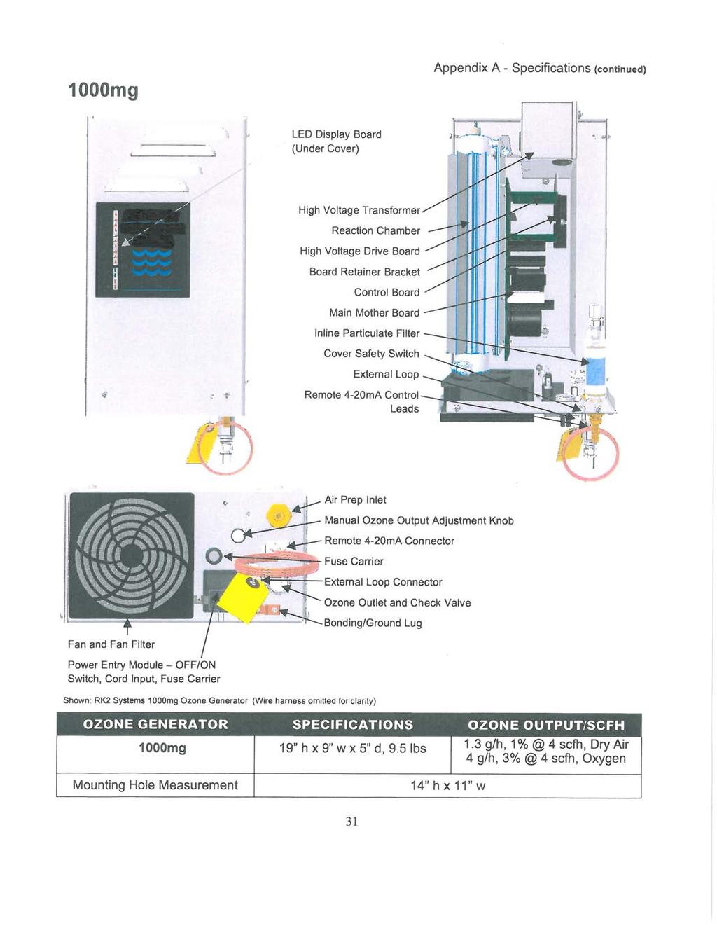
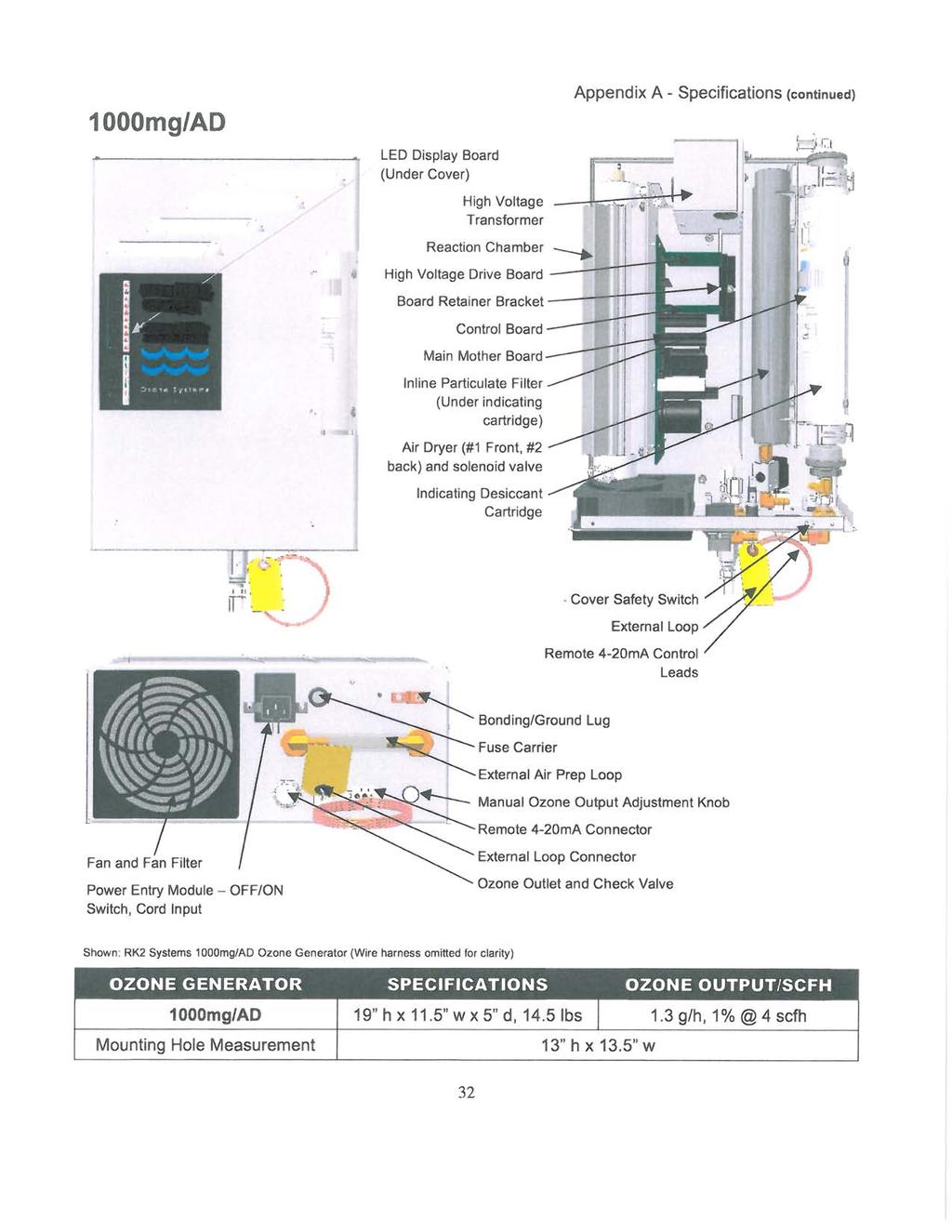
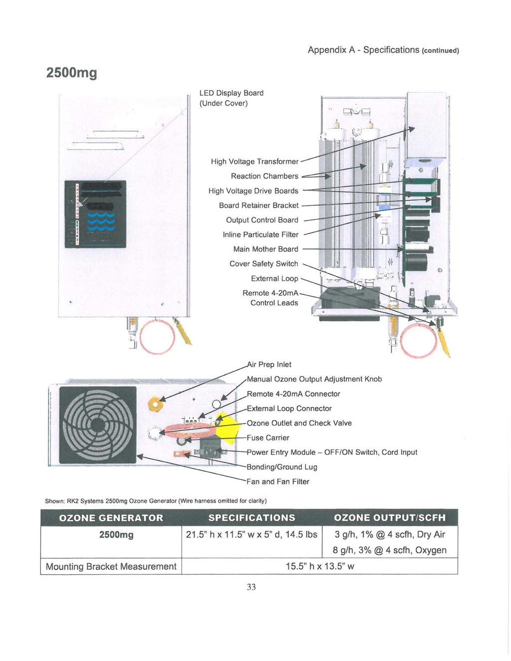
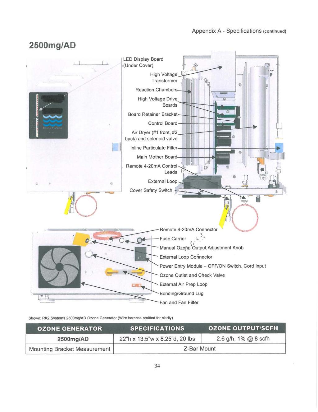
32 APPENDIX A - Specifications Air Prep System Shown: RK2 Systems 8 SCFH Oxygen Air Prep System with Cover Shown: RK2 Systems 8 SCFH Oxygen Air Prep System with out Cover AIR PREP SYSTEM SPECIFICATIONS OXYGEN OUTPUT/SCFH SCFH 15.5 h x 17 w x 16 d, 45 lbs 90% 8 scfh (Workhorse 8c) (with cover) PDA20 (LPSA20) 15.5 h x 17 w x 16 d, 45 lbs (with cover) scfh
33
34
35
36
Air Preparation System
 Theory of Operation/Product Description (continued) THEORY OF OPERATION/PRODUCT DESCRIPTION CHAPTER 1 RK2 Systems ozones are designed for safe, effective use in a variety of water treatment applications.
Ozone Systems. Installation & Operation Manual CD15nx CD30nx. Corona Discharge Ozone Generators. ClearWater Tech, LLC. Integrated Ozone Systems
 Ozone Systems Installation & Operation Manual CD15nx CD30nx Corona Discharge Ozone Generators ClearWater Tech, LLC. Integrated Ozone Systems 850-E Capitolio Way, San Luis Obispo, Ca 93401 805-549-9724
Click Here to View Available HD03-III at ssllc.com>> Ozone Systems. Installation & Operation Manual. High Dissolved Ozone Generation System
 Click Here to View Available HD03-III at ssllc.com>> Ozone Systems Installation & Operation Manual HDO 3 Series High Dissolved Ozone Generation System Nonfood Compounds Program Listed ClearWater Tech,
Electrical Field. Molecular weight: 48. Color: Solubility: Ozone leaves no telltale taste or odor.
 O 3 Introduction... This Installation and Operation Manual is written to assist in the installation, operation and maintenance of ozone delivery systems manufactured by RK2 Systems Inc. The equipment has
Ozone Generator Systems
 PZ2-1 & PZ2-2 - Commercial and Residential Pools & Spas Ozone Generator Systems INSTALLATION GUIDE and OPERATION MANUAL T. O3 NATURAL TECHNOLOGY Reduces Chemical Usage, Improves Sanitation Produces Crystal
PZ2 Series Manual. PROZONE INTERNATIONAL, Inc. Ozone Water Purification Systems. INSTALLATION GUIDE and OPERATION MANUAL. Prozone PZ2 Series
 PZ2 Series Manual PROZONE INTERNATIONAL, Inc. Ozone Water Purification Systems INSTALLATION GUIDE and OPERATION MANUAL Prozone PZ2 Series Ozone Generator Systems SAFETY READ AND FOLLOW ALL INSTRUCTIONS.
Ozone Systems. Installation & Operation Manual POE10 POE12. Corona Discharge Ozone Generators. ClearWater Tech, LLC. Integrated Ozone Systems
 Ozone Systems Installation & Operation Manual POE10 POE12 Corona Discharge Ozone Generators ClearWater Tech, LLC. Integrated Ozone Systems 850-E Capitolio Way, San Luis Obispo, Ca 93401 805-549-9724 Fax:
Ozone Generator Systems
 PZ2-4V - Commercial and Residential Pools & Spas Ozone Generator Systems INSTALLATION GUIDE and OPERATION MANUAL T. O3 NATURAL TECHNOLOGY Reduces Chemical Usage, Improves Sanitation Produces Crystal Clear
PZ1, PZ3 & PZ6 Installation Guide
 PZ1, PZ3 & PZ6 Installation Guide PROZONE INTERNATIONAL, INC. Ozone Water Purification Systems INSTALLATION GUIDE Prozone PZ1, PZ3 and PZ6 Series Ozone Generator Systems SAFETY READ AND FOLLOW ALL INSTRUCTIONS.
EcoMaster - Residential Pools up to 40,000 Gallons
 - Residential Pools up to 40,000 Gallons INSTALLATION/ OPERATION GUIDE Reduces Chemical Usage, Improves Sanitation Produces Crystal Clear Water Copyright 2013 Prozone Water Products: 3004 11 th Ave. -
IMPORTANT SAFETY INSTRUCTIONS EC-AG1-25 EC-AG1, EC-AG2 SAVE THESE INSTRUCTIONS.
 IMPORTANT SAFETY INSTRUCTIONS 2 1. Read and Follow All Instructions 2. Read this manual completely before attempting installation. 3. All permanent electrical connections should be made by a qualified
Next Generation Corona Discharge Installation & Operation Manual
 Next Generation Corona Discharge Installation & Operation Manual 4-2319-01 Rev.A IMPORTANT SAFETY INSTRUCTIONS READ & FOLLOW ALL INSTRUCTIONS Read this manual completely before attempting installation.
Vacuum-ultraviolet Ozone Systems. Installation & Operation Manual. Model OZ-SPA
 OzoneAX 3 T Vacuum-ultraviolet Ozone Systems Installation & Operation anual odel OZ-SPA A. Important Safety Instructions IPORTANT SAFETY INSTRUCTIONS When using this electrical equipment, basic safety
EcoMaster - Residential Pools up to 40,000 Gallons
 - Residential Pools up to 40,000 Gallons INSTALLATION/ OPERATION GUIDE Reduces Chemical Usage, Improves Sanitation Produces Crystal Clear Water PROZONE Copyright 2018 Prozone Water Products: 3004 11 th
T E C H, L L C. Ozone Systems. Ozone System. CD-20/O2 Corona Discharge Ozone Generator. Installation & Owner s Manual
 T E C H, L L C. Ozone Systems Ozone System CD-20/O2 Corona Discharge Ozone Generator Installation & Owner s Manual P.O. BOX 15330, San Luis Obispo, CA 93406 Copyright 1994 - ClearWater Tech, Inc. Reproduction
Ozone + UV Sanitation
 Ozone + UV Sanitation Installation Manual 4-2177-01 Rev.C IMPORTANT SAFETY INSTRUCTIONS When installing and operating the DEL Spa Solar Eclipse, basic precautions should always be followed: READ AND FOLLOW
READ AND FOLLOW ALL INSTRUCTIONS SAVE THESE INSTRUCTIONS
 READ AND FOLLOW ALL INSTRUCTIONS SAVE THESE INSTRUCTIONS 1 IMPORTANT SAFETY INSTRUCTIONS Read the instructions The appliance is not to be used by persons (including children) with reduced physical, sensory
Installation Instructions. For the 18 Built-In Dishwasher and Front Color Panels
 Installation Instructions For the 18 Built-In Dishwasher and Front Color Panels Printed in USA 154232102 Before You Begin DO NOT INSTALL DISHWASHER UNTIL YOU HAVE READ ALL INSTRUCTIONS. FOR YOUR SAFETY,
DRY AIR SYSTEMS, INC Metro Boulevard Maryland Heights, Missouri (314) fax (314)
 fax (314)") DRY AIR SYSTEMS, INC. 2655 Metro Boulevard Maryland Heights, Missouri 63043 (314) 344-1114 fax (314) 344-0677 HD SERIES DRIERS TABLE OF CONTENTS WHY AN AIR DRYER 3 WHAT IS A DESICCANT AIR DRYER 3 Desiccant
DRY AIR SYSTEMS, INC. 2655 Metro Boulevard Maryland Heights, Missouri 63043 (314) 344-1114 fax (314) 344-0677 HD SERIES DRIERS TABLE OF CONTENTS WHY AN AIR DRYER 3 WHAT IS A DESICCANT AIR DRYER 3 Desiccant
LABORATORY ULTRA ZERO AIR GENERATOR. ZAC-ULT Series USER MANUAL
 LABORATORY ULTRA ZERO AIR GENERATOR ZAC-ULT Series USER MANUAL 166 Keystone Drive Montgomeryville, PA 18936 Telephone: 215-641-2700 Fax: 215-641-2714 Email: mtgmmville@matheson-trigas.com INT-0261-XX rev
Clear Comfort Residential Pool & Spa Sanitization System Installation, Operations & Maintenance Manual
 Clear Comfort Residential Pool & Spa Sanitization System Installation, Operations & Maintenance Manual IMPORTANT SAFETY INSTRUCTIONS For Further Assistance Contact Us: 303.872.4477 support@clearcomfort.com
Safety. Rinse Kit for Multi-Pro 1200 and 1250 Turf Sprayers Model No Safety and Instructional Decals. Installation Instructions
 Rinse Kit for Multi-Pro 1200 and 1250 Turf Sprayers Model No. 106-4842 Form No. 3353-529 Rev B Installation Instructions Note: Determine the left and right sides of the machine from the normal operating
TG-10 Wall Mount Installation and Operation Manual. High Output Ozone Generator
 TG-10 Wall Mount Installation and Operation Manual High Output Ozone Generator Ozone Solutions 451 Black Forest Road Hull, IA 51239 Phone: (712) 439-6889 Fax: (712) 439-6733 2 Table of Contents Safety
Important Safety Instructions
 8 THE BUBBLE MIST STOPS COMING BACK INTO THE POOL: Note: Our suction side installation method requires a portion of the pump s power. Anything affecting the pump s performance affects our air draw. Under
Ozone Systems CD15/AD & M15AD. Installation & Maintenance Manual. Corona Discharge Ozone Generator. ClearWater Tech, LLC. ...
 Ozone Systems... Installation & Maintenance Manual CD15/AD & M15AD Corona Discharge Ozone Generator ClearWater Tech, LLC. Integrated Ozone Systems 850-E Capitolio Way, San Luis Obispo, Ca 93401 805-549-9724
FOR THE RECORD. You should record the model and serial numbers, which can be found on the back of the unit, for future reference.
 FOR THE RECORD You should record the model and serial numbers, which can be found on the back of the unit, for future reference. Warranty: 18 mo. on unit and 1 year on check valve assembly Model: The Ozone
1-866-PENNERS
 Cascade Premier and Elite Premier Bathing Systems with Aqua-Aire Installation / Assembly Instructions Premier Elite Premier PENNER PATIENT CARE, INC Box 523 / 102 Grant St. Aurora, NE 68818 360745P Revision
Installation & Operation Manual. AromaFlo. mr.steam. Feel Good Inc.
 Installation & Operation Manual AromaFlo Feel Good Inc. WARNING Risk of electric shock - This pump is supplied with a grounding conductor and grounding-type attachment plug. To reduce the risk of electric
VMUS-4 Ozone Generator
 VMUS-4 Ozone Generator Installation and Operation Manual pg. 1 Cautions, Warnings and Hazards Refer to the manual of the ozone generating system first, to assure proper location of all ozone equipment.
DISHWASHER. Models DW2432 and DW2432SS. Installation Manual. Write Serial Number (on inner door of unit) here:
 here:") DISHWASHER Models DW2432 and DW2432SS Installation Manual Write Serial Number (on inner door of unit) here: Felix Storch, Inc. Summit Appliance Division 770 Garrison Avenue Bronx, New York 10474 www.summitappliance.com
DISHWASHER Models DW2432 and DW2432SS Installation Manual Write Serial Number (on inner door of unit) here: Felix Storch, Inc. Summit Appliance Division 770 Garrison Avenue Bronx, New York 10474 www.summitappliance.com
HEATLESS DESICCANT AIR DRYER INSTRUCTION & MAINTENANCE MANUAL
 HEATLESS DESICCANT AIR DRYER INSTRUCTION & MAINTENANCE MANUAL H-Series & 203 THRU 223 SERIES ARROW PNEUMATICS, INC. REGENERATIVE DRYER DIVISION 2111 WEST 21ST STREET BROADVIEW, IL 60155 708-343-9595 708-343-1907
Installation Instructions for. OmniFount
 Installation Instructions for OmniFount Congratulations, you have just purchased the finest watering fountain on the market. This unit is built to give you excellent service when properly installed and
BUILT-IN DISHWASHER INSTALLATION INSTRUCTIONS
 BUILT-IN DISHWASHER INSTALLATION INSTRUCTIONS PLEASE READ COMPLETE INSTRUCTIONS BEFORE YOU BEGIN LEAVE INSTALLATION INSTRUCTIONS AND USER'S GUIDE WITH OWNER ALL ELECTRIC WIRING AND PLUMBING MUST BE DONE
INSTALLATION INSTRUCTIONS
 ,t_2007 Lennox Industries Inc. Dallas, Texas, USA INSTALLATION INSTRUCTIONS CH33 Series Units EVAPORATOR 505,264M (65484504) 10/07 Supersedes 09/06 COILS n _putech blications ical Litho U.S.A. RETAIN THESE
WATER PURIFYING SYSTEM
 ECO FRIENDLY PARAMOUNT CERTIFIED WATER PURIFYING SYSTEM INSTALLATION MANUAL 004-027-8818-00 REV 060116 US and Foreign patents and patents pending see www.1paramount.com/about/patents/ 295 East Corporate
P4200PM / P5000PM Remote Air Dryer User s Guide
 P4200PM / P5000PM Remote Air Dryer User s Guide 1. Welcome & Congratulations Congratulations on your purchase of a new PUREGAS P4200PM / P5000PM Air Dryer! We here at PUREGAS are very proud of our products
Cascade Premier and Elite Premier Bathing Systems with Aqua-Aire Installation / Assembly Instructions
 Cascade Premier and Elite Premier Bathing Systems with Aqua-Aire Installation / Assembly Instructions Premier Elite Premier PENNER PATIENT CARE, INC Box 523 / 102 Grant St. Aurora, NE 68818 360745P Revision
READ AND FOLLOW ALL INSTRUCTIONS SAVE THESE INSTRUCTIONS
 READ AND FOLLOW ALL INSTRUCTIONS SAVE THESE INSTRUCTIONS International Patent #9,938,166 Patented Micro-Ozone cell ozone technology: Patent #8367007 1 IMPORTANT SAFETY INSTRUCTIONS Read the maintenance
Installation GUIDE VDWU524SS VDWU524WSSS FDWU524WS FDWU524 VDWU324SS FDWU324
 Installation GUIDE VDWU524SS VDWU524WSSS FDWU524WS FDWU524 VDWU324SS FDWU324 To prevent accidents, which could cause serious injury or death, as well as machine damage read these instructions before installation
OZONE SYSTEM FOR IN-GROUND POOLS New and Existing
 INSTALLATION & OPERATIONS MANUAL FOR Z0-910/912 OZONE SYSTEM FOR IN-GROUND POOLS New and Existing MANUFACTURED BY 3428 Bullock Lane San Luis Obispo, CA 93401 800-676-1335 4-0454-041900/03 IMPORTANT SAFETY
Ozomax Ltd Ozone generators
 Ozomax Ltd Page - 1 Ozomax Ltd Ozone generators OZONATORS VTTL series OZO 1VTTL to OZO 50 VTTL General specifications / installation and maintenance instructions Ozomax would like to congratulate you on
WILKERSON MODELS DE3, DE4 AND DE5 COMPACT HEATLESS AIR DRYERS
 INSTRUCTION MANUAL FOR WILKERSON MODELS DE3, DE4 AND DE5 COMPACT HEATLESS AIR DRYERS DE3 - DE5 OPERATIONS GENERAL This instruction manual covers the installation, operation, maintenance and troubleshooting
Professional Series. Chemical Feed System Model # US Patent No. 6,752,930 B2
 Professional Series Chemical Feed System Model # 22152-02 US Patent No. 6,752,930 B2 Product Manual SureWater Technologies, Inc. The Solution X-2 Model # 22152-02 Table of Contents 1. Installation Instruction
TRI-PLATE B INSTALLATION, OPERATION, AND MAINTENANCE INSTRUCTIONS PART NO EFFECTIVE MARCH 1, 1983 REPRINT APRIL 16, 1999
 TRI-PLATE B INSTALLATION, OPERATION, AND MAINTENANCE INSTRUCTIONS PART NO. 8801469 EFFECTIVE MARCH 1, 1983 REPRINT APRIL 16, 1999 THE MILK COOLING SYSTEMS SPECIALISTS TM FRE-HEATER Part No. 8801469 Table
Installation Instructions
 Installation Instructions For Fully Integrated NoFrost Combined Refrigerator-Freezers HC 2060/2061 7082 485-00 Important PLEASE READ AND FOLLOW THESE INSTRUCTIONS These instructions contain Warning and
Installation Instructions
 Installation Instructions For Fully Integrated NoFrost Combined Refrigerator-Freezers HC 2062 HCB 2062 HC/HCB 20 7082 373-00 Important PLEASE READ AND FOLLOW THESE INSTRUCTIONS These instructions contain
CELDEK Evaporative Cooler Module Installation, Operation, and Maintenance Manual. CELDEK Evaporative Cooler
 CELDEK Evaporative Cooler Module Installation, Operation, and Maintenance Manual CELDEK Evaporative Cooler RECEIVING AND INSPECTION Upon receiving unit, check for any interior and exterior damage, and
COMPRESSED AIR DRYER. SAFETY... Page 2 MAINTENANCE... Page 5. INSTALLATION... Page 3 PARTS AND KITS... Page 6
 OWNERS MANUAL BOSS COMPRESSED AIR DRYER Distributed by Air & Vacuum Process, Inc. Phone: 281-866-9700 Fax: 281-866-9717 Email: sales@airvacuumprocess.com SAFETY... Page 2 MAINTENANCE... Page 5 INSTALLATION...
Instruction Manual - Anti-Siphon Ejector Chlorine & Sulfur Dioxide 500 PPD (10 kg/h) Maximum Capacity
 Maximum Capacity") - Anti-Siphon Ejector Chlorine & Sulfur Dioxide 500 PPD (10 kg/h) Maximum Capacity 100 PPD (2 kg/h) Chlorine or Sulfur Dioxide 250 & 500 PPD (5 & 10 kg/h) Chlorine or Sulfur Dioxide Anti-Siphon Ejector
- Anti-Siphon Ejector Chlorine & Sulfur Dioxide 500 PPD (10 kg/h) Maximum Capacity 100 PPD (2 kg/h) Chlorine or Sulfur Dioxide 250 & 500 PPD (5 & 10 kg/h) Chlorine or Sulfur Dioxide Anti-Siphon Ejector
INSTALLATION INSTRUCTIONS
 INSTALLATION INSTRUCTIONS VARIABLE SPEED BOOSTER PUMP IMPORTANT SAFETY INSTRUCTIONS READ AND FOLLOW ALL INSTRUCTIONS SAVE THESE INSTRUCTIONS IMPORTANT SAFETY INFORMATION WARNING: RISK OF ELECTRICAL SHOCK
Sundance Spas SPA EQUIPMENT SYSTEM. Installation Instructions. P/N Rev. A
 Sundance Spas SPA EQUIPMENT SYSTEM Installation Instructions P/N 6530-456 Rev. A Contents Important Notices 1 Important Safety Instructions 2 Where to Place the Equipment System 3 Connecting Pipes Between
HTU-500 Ozone Generator
 HTU-500 Ozone Generator Installation and Operation Manual pg. 1 Cautions, Warnings and Hazards Refer to the manual of the ozone generating system first, to assure proper location of all ozone equipment.
CONTENTS CONSIDERATIONS. General Plumbing Component Connection ILLUSTRATION. Control System CONFIGURATION. Voltage Verification CONNECTION
 AIR SERIES SYSTEM INSTALLATION MANUAL CONTENTS CONSIDERATIONS General Plumbing Component Connection 2 2 2 ILLUSTRATION Control System 3 CONFIGURATION Voltage Verification 4 CONNECTION Component Connection
P6500W Air Dryer User s Guide
 P6500W Air Dryer User s Guide 1. Welcome & Congratulations Congratulations on your purchase of a new PUREGAS P6500W Air Dryer! We here at PUREGAS are very proud of our products and we are committed to
Title: YALE OFFICE OF FACILITIES PROCEDURE MANUAL Chapter: 01 - Yale Design Standard Division: HVAC Standards
 Date Description of Change Pages / Sections Modified ID 6/15/16 Entire document - mgl44 PART 1 - INTRODUCTION 1.1 PURPOSE A. This section is intended to define the general installation and minimum product
Installation Instructions
 Installation Instructions For NoFrost Combined Refrigerator-Freezers with IceMaker CS/CBS 20 7084 337-00 Important Please Read and Follow these Instructions These instructions contain Danger, Warning and
SuperKlean Washdown Products
 February 2012 DURAMIX 8000 INSTALLATION AND MAINTENANCE INSTRUCTIONS **DO NOT THROW AWAY AFTER INSTALLATION** **SAVE AND DISPLAY PROMINENTLY WHERE THIS EQUIPMENT IS USED** WARNING HIGH PRESSURE AND HOT
EXTREME HP-1 Reverse Osmosis System
 EXTREME HP-1 Reverse Osmosis System Leader Evaporator Co., Inc. 49 Jonergin Drive Swanton, VT 05488 Tel: 802-868-5444 www.leaderevaporator.com TABLE OF CONTENTS INTRODUCTION... 4 THEORY OF OPERATION...
INSTALLATION INSTRUCTIONS
 2008 Lennox Industries Inc. Dallas, Texas, USA INSTALLATION INSTRUCTIONS CH33 Series Units EVAPORATOR COILS 505,264M (65484504) 05/08 Supersedes 10/07 Litho U.S.A. RETAIN THESE INSTRUCTIONS FOR FUTURE
Copyright. Prozone Water Products,Inc. phone: fax:
 Ozone Generator Systems for Pools and Spas Copyright. Prozone Water Products,Inc. Pioneers of Ozone Prozone pioneered the original Very Ultra Violet ozone generator cartridge in 1977 for the swimming pool
Installation Instructions
 Installation Instructions For Fully Integrated NoFrost Combined Refrigerator-Freezers HC 2060/2061 HCB 2060/2061 7084 349-00 Important Please Read and Follow these Instructions These instructions contain
LC Series - Light Commercial Pump Station Installation and Operation Manual
 LC Series - Light Commercial Pump Station Installation and Operation Manual Please keep this manual with the pump station Content Rain Bird LC Series Overview... Safety Instruction... Operation... 3 Pump
Installation Instructions
 Installation Instructions For Fully Integrated NoFrost Combined Refrigerator-Freezers HC 2062 HCB 2062 HC/HCB 2062 7084 341-00 Important Please Read and Follow these Instructions These instructions contain
Dual Column Dehydrating Breather Manual
 Dual Column Dehydrating Breather Manual DCB-MANUAL 1.6 Read and understand this manual prior to operating or servicing the products. SPX Transformer Solutions, Inc., Service & Components Division U.S.
VSA Series Air Dryer. User s Guide
 VSA Series Air Dryer User s Guide Models covered: VSA1 VSA2 VSA3 VSA4 1. Welcome & Congratulations Congratulations on your purchase of a new PUREGAS VSA SERIES AIR DRYER! We here at PUREGAS are very proud
TG-Series. Installation & Operations Manual. Model: TG-75, TG-150, TG-300, TG-450, TG-600. Water Cooled Ozone Generator
 TG-Series Water Cooled Ozone Generator Model: TG-75, TG-150, TG-300, TG-450, TG-600 Installation & Operations Manual 451 Black Forest Road, Hull, Iowa, 51239 712.439.6880 info@ozonesolutions.com www.ozonesolutions.com
WM-450-PT WM-900-PT Commercial Wall Mounted Reverse Osmosis
 WM-450-PT WM-900-PT Commercial Wall Mounted Reverse Osmosis Installation And Service Manual Watts Pure Water 1725 W. Williams Dr. C-20., Phoenix, Arizona 85027 Phone: 888-774-7405 Fax: 602-588-0356 www.wattspurewater.com
Installation Manual PS-225 & PS-275
 Installation Manual PS-225 & PS-275 Table of Contents Pre-Uncrating Checklist... 1 Verifying System Requirements... 2 Verifying System Direction... 2 Verifying the Electrical Requirements... 2 Removal
Owner s Manual. Keep with machine for reference PKC24 INSTALLATION & OPERATION REV Perlick Corporation 8300 W Good Hope Rd Milwaukee, WI 53223
 Owner s Manual Keep with machine for reference PKC24 INSTALLATION & OPERATION REV.11.09 Perlick Corporation 8300 W Good Hope Rd Milwaukee, WI 53223 800-558- 5592 FAX 414-353- 7069 perlick.com TABLE OF
INSTALLATION INSTRUCTIONS
 INSTALLATION INSTRUCTIONS Series Units RETAIN THESE INSTRUCTIONS FOR FUTURE REFERENCE WARNING Improper installation, adjustment, alteration, service or maintenance can cause personal injury, loss of life,
TIDALWAVE I/G POOL PUMP INSTRUCTION MANUAL
 TIDALWAVE I/G POOL PUMP INSTRUCTION MANUAL READ THIS MANUAL CAREFULLY BEFORE USING YOUR PUMP 88 PUMP PARTS BREAKDOWN REF # Order # Mfr # Description 1 NEP4 AC 348 Lid Knobs NEP AC 380 Strainer Lid 3 NEP6
Instructions for Model E782 Betman Cleaning System (Cleaner/Rinser/Rinser/Dryer)
") 1 2 Esma Inc. PO Box 734 450 W. Taft Drive South Holland, IL 60473 708-331-1855 800-276-2466 FAX 708-331-8919 Introduction Instructions for Model E782 Betman Cleaning System (Cleaner/Rinser/Rinser/Dryer)
1 2 Esma Inc. PO Box 734 450 W. Taft Drive South Holland, IL 60473 708-331-1855 800-276-2466 FAX 708-331-8919 Introduction Instructions for Model E782 Betman Cleaning System (Cleaner/Rinser/Rinser/Dryer)
HYDROGEN SULFIDE REMOVAL SYSTEMS
 OX120U5, OX120U10 OX120B5, OX120B10 OX120U10R & OX120U5R INSTALLATION, OPERATION & SERVICE INSTRUCTIONS HYDROGEN SULFIDE REMOVAL SYSTEMS NO MEDIA NO CHEMICALS NO WASTE PRESSURE BOOSTING SYSTEM MODELS:
Standard and CELDEK Evaporative Cooler Modules Installation, Operation, and Maintenance Manual
 Standard and CELDEK Evaporative Cooler Modules Installation, Operation, and Maintenance Manual Standard Evaporative Cooler CELDEK Evaporative Cooler RECEIVING AND INSPECTION Upon receiving unit, check
Installation Instructions
 Installation Instructions For Fully Integrated NoFrost Combined Refrigerator-Freezers HCB 1560/1561 HC 1550 7084 327-00 Important Please Read and Follow these Instructions These instructions contain Danger,
Installation Instructions for. CattleMaster Series Fountains
 Installation Instructions for CattleMaster Series Fountains Congratulations, you have just purchased the finest watering fountain on the market. This unit is built to give you excellent service when properly
Dishwasher Installation Manual
 Dishwasher Installation Manual DW 51600 SS DW 51600 FBI DWT 51600 SS DWT 51600 FBI DWT 81800 FBI DWT 81800 SS DWT 81800 SSIH DWT 81800 SSWS DWT 52600 WIH DWT 52600 SSIH DWT 52600 BIH DWT 52800 WIH DWT
ACT Cartridge Dust Collector
 IOM-101-1 ACT Cartridge Dust Collector Installation and Operation Manual ACT Dust Collectors CAUTION! Accidents happen, be careful and always follow all local and federal regulations! Fires and explosions
Installation Instructions
 Installation Instructions For NoFrost Combined Refrigerator-Freezers with IceMaker CS 2060, CS 2061 7084 339-00 Important Please Read and Follow these Instructions These instructions contain Danger, Warning
Electric Mini Tank Water Heaters ME10 ME25 ME40 ME60
 Electric Mini Tank Water Heaters ME10 ME25 ME40 ME60 Installation and Operating Instruction Manual V01.2018 Table of Contents Important Safety Instructions 3 General Information 3/6 Technical Data 4-5
INSTALLATION INSTRUCTIONS FOR 8330*5511 MOUNTING KIT
 RV Products Division INSTALLATION INSTRUCTIONS FOR 8330*5511 MOUNTING KIT 8330-752 CONTROL BOX KIT (12 VDC COOL ONLY) 9330A755 CONTROL BOX KIT (12 VDC HEAT/COOL) 8530-750 CONTROL BOX KIT (24 VAC COOL ONLY)
SECTION COMPRESSED AIR SYSTEM. A. Pipe and pipe fittings, including valves, unions and couplings.
 SECTION 15481 COMPRESSED AIR SYSTEM PART 1 - GENERAL 1.1 SECTION INCLUDES A. Pipe and pipe fittings, including valves, unions and couplings. B. Air compressor. C. After cooler. D. Refrigerated air dryer.
MODEL CMA-180UC PARTS MANUAL Rev 1.16
 MODEL CMA-180UC PARTS MANUAL Rev 1.16 CMA DISHMACHINES 12700 KNOTT STREET GARDEN GROVE, CALIFORNIA 92841 800-854-6417 FAX 714-895-2141 wwwcmadishmachines.com TABLE OF CONTENTS MODEL CMA-180UC 1. PARTS
PRE-ASSEMBLED RADIANT CONTROL PANEL INSTALLATION MANUAL
 FloorHeat PRE-ASSEMBLED RADIANT CONTROL PANEL INSTALLATION MANUAL Thank you for purchasing this radiant control panel assembly. Following are some important notes that will make the installation successful.
Installing the Cisco ONS FAP-4 Fuse Alarm Panel
 Installing the Cisco ONS 15454-FAP-4 Fuse Alarm Panel Product Number: 15454-FAP-4= This document explains how to install, test, operate, and maintain the Cisco ONS 15454-FAP-4 fuse alarm panel. This document
OPERATING MANUAL MODEL AIR 1500TM AIR DRYER
 OPERATING MANUAL MODEL AIR 500TM AIR DRYER Puregas, LLC 226-A Commerce St. Tel: 800-52-535 Broomfield, Colorado Fax: 303-657-2205 P/N P0255 REV A, 02/9/4 TABLE OF CONTENTS.0 GENERAL... 3 2.0 SPECIFICATIONS...
Installation Instructions
 Installation Instructions For Fully Integrated NoFrost Combined Refrigerator-Freezers HCB 1560/1561 7084 429-00 Important Please read and follow these instructions These instructions contain Danger, Warning
SYSTEMS for CATALYTIC FILTERS
 OP40U5F, OP40B5F, OP80U10F, OP80B10F, OP120U15F & OP120B15F INSTALLATION, OPERATION & SERVICE INSTRUCTIONS Hydrogen Sulfide Removal SYSTEMS for CATALYTIC FILTERS NO DIAPHRAGMS OR AIR CELLS COMPLETELY CORROSION
HG-1500 Ozone Generator
 HG-1500 Ozone Generator Manual Ozone Solutions Thanks You For Purchasing Our Products Ozone Solutions, Inc. HG-1500 Ozone Generator With proper care and maintenance, this device should give you years of
J120 STEAM BOOSTER INSTALLATION, OPERATION, AND SERVICE MANUAL J120 STEAM BOOSTER. J120 Steam Booster Manual D
 INSTALLATION, OPERATION, AND SERVICE MANUAL J120 STEAM BOOSTER J120 STEAM BOOSTER J120 Steam Booster Manual REVISION HISTORY Revision Letter Revision Date Made by Applicable ECNs Details A 10-27-04 CBW
WAIWELA SERIES-TWO WATER HEATERS
 WAIWELA SERIES-TWO WATER HEATERS ELECTRIC INSTANTANEOUS WATER HEATER INSTALLATION GUIDE AND OWNERS MANUAL MODELS COVERED WET-12 T, TC, T2-240/208 V SPECIAL, V READ THE GENERAL SAFETY SECTION BEGINNING
UHIR Series. Horizontal or Vertical Mounting Industrial / Commercial Electric Unit Heater. Owner s Manual
 UHIR Series Horizontal or Vertical Mounting Industrial / Commercial Electric Unit Heater Owner s Manual This manual covers installation, maintenance and repair parts. Read carefully before attempting to
Installation Instructions
 Installation Instructions For Fully Integrated NoFrost Combined Refrigerator-Freezers HC 2062 HCB 2062 HC/HCB 2062 7084 445-00 Important Please read and follow these instructions These instructions contain
ECONO FLO 2.7HP VARIABLE SPEED PUMP OWNER S MANUAL
 ECONO FLO 2.7HP VARIABLE SPEED PUMP OWNER S MANUAL IMPORTANT SAFETY INSTRUCTIONS READ AND FOLLOW ALL INSTRUCTIONS SAVE THESE INSTRUCTIONS WARNING: Before installing this product, read and follow all warning
Standard and CELDEK Evaporative Cooler Modules Installation, Operation, and Maintenance Manual
 Standard and CELDEK Evaporative Cooler Modules Installation, Operation, and Maintenance Manual Standard Evaporative Cooler CELDEK Evaporative Cooler RECEIVING AND INSPECTION Upon receiving unit, check
SMF PUMP OWNER S MANUAL
 SMF PUMP OWNER S MANUAL IMPORTANT SAFETY INSTRUCTIONS READ AND FOLLOW ALL INSTRUCTIONS SAVE THESE INSTRUCTIONS WARNING: Before installing this product, read and follow all warning notices and instructions
MDH Series Air Dryer. User s Guide
 MDH Series Air Dryer User s Guide Models covered: MDH1 MDH2 MDH3 MDH4 MDH5 MDH6 1. Welcome & Congratulations Congratulations on your purchase of a new PUREGAS MDH SERIES AIR DRYER! We here at PUREGAS
Installation and Operation Manual. ACF-18 Automatic Chlorinating Feeder
 Installation and Operation Manual ACF-18 Automatic Chlorinating Feeder Operating Specifications Inlet Flow: 1.0-1.5 gpm Outlet Flow: = Inlet Flow Inlet Pressure: 10-45 psi Maximum Output: 26 lbs. of Available
EXHAUST PURGE DESICCANT AIR DRYER INSTRUCTION & MAINTENANCE MANUAL MODEL RE-231 THROUGH RE-252
 EXHAUST PURGE DESICCANT AIR DRYER INSTRUCTION & MAINTENANCE MANUAL MODEL RE-231 THROUGH RE-252 ARROW PNEUMATICS, INC. REGENERATIVE DRYER DIVISION 500 NORTH OAKWOOD RD LAKE ZURICH, IL,60047 PHONE # (847)
INSTANT HOT WATER DISPENSER
 INSTANT HOT WATER DISPENSER Tank Installation Materials required (not provided) 2 mounting bracket screws (and 2 plastic anchors if attaching to drywall) Shut-Off valve and T fitting Components When you