Multi Air Conditioner Indoor Unit SVC MANUAL(General)
|
|
|
- Hugo Fields
- 5 years ago
- Views:
Transcription
1 Internal Use Only Multi Air Conditioner Indoor Unit SVC MANUAL(General) CAUTION Before Servicing the unit, read the safety precautions in General SVC manual. Only for authorized service personnel.
2 Air Conditioner Service Manual TABLE OF CONTENTS Part 1 General Information...3 Safety Precaution...4 External Appearance...7 Nomenclature...8 Part 2 Functions & Controls List of Functions & Controls Air Flow Air Purifying Installation Functions Reliability Convenience Functions & Controls Special Function & KIT...28 Part 3 Trouble shooting guide
3 Part 1 General Information 1. Safety Precautions External Appearance Nomenclature
4 Part 1 General Information 1. Safety Precautions To prevent injury to the user or other people and property damage, the following instructions must be followed. Incorrect operation due to ignoring instruction will cause harm or damage. The seriousness is classified by the following indications. This symbol indicates the possibility of death or serious injury. This symbol indicates the possibility of injury or damage to properties only. Meanings of symbols used in this manual are as shown below. Be sure not to do. Be sure to follow the instruction. Dangerous Voltage 1.1 Cautions in Repair Be sure to disconnect the power cable plug from the plug socket before disassembling the equipment for a repair.internal components and circuit boards are at main potential when the equipment is connected to the power cables. This voltage is extremely dangerous and may cause death or severe injury if come in contact with it. Do not touch the discharging refrigerant gas during the repair work. The discharging refrigerant gas.the refrigerant gas can cause frostbite. Release the refrigerant gas completely at a well-ventilated place first. Otherwise, when the pipe is disconnected, refrigerant gas or refrigerating machine oil discharges and it Can cause injury. When the refrigerant gas leaks during work, execute ventilation. If the refrigerant gas touches to a fire, poisonous gas generates. A case of leakage of the refrigerant and the closed room full with gas is dangerous because a shortage of oxygen occurs. Be sure to execute ventilation. When removing the front panel or cabinet, execute short-circuit and discharge between high voltage capacitor terminals. If discharge is not executed, an electric shock is caused by high voltage resulted in a death or injury. Do not turn the air-conditioner ON or OFF by plugging or unplugging the power plug. There is risk of fire or electrical shock
5 Part 1 General Information Do not use a defective or underrated circuit breaker. Use the correctly rated breaker and fuse. Otherwise there is a risk of fire or electric shock. Install the panel and the cover of control box securely. Otherwise there is risk of fire or electric shock due to dust, water etc. Indoor/outdoor wiring connections must be secured tightly and the cable should be routed properly so that there is no force pulling the cable from the connection terminals. Improper or loose connections can cause heat generation or fire. Do not touch, operate, or repaire the product with wet hands. Hoding the plug by hand when taking out. Otherwise there is risk of electric shock or fire. Do not turn on the breaker under condition that front panel and cabinet are removed. Be sure to earth the air conditioner with an earthing conductor connected to the earthing terminal. Conduct repair works after checking that the refrigerating cycle section has cooled down sufficiently. Otherwise, working on the unit, the hot refrigerating cycle section can cause burns. Do not tilt the unit when removing panels. Otherwise, the water inside the unit can spill and wet floor. Do not use the welder in a well-ventilated place. Using the welder in an enclosed room can cause oxygen deficiency. Be sure to turn off power switch before connect or disconnect connector, or parts damage may be occurred
6 Part 1 General Information 1.2 Inspections after Repair Check to see if the power cable plug is not dirty or loose. If the plug is dust or loose it can cause an electrical shock or fire. Do not use a joined power cable or extension cable, or share the same power outlet with other electrical appliances. otherwise, it can cause an electrical shock, excessive heat generation or fire. Do not insert hands or other objects through the air inlet or outlet while the product is operating. There are sharp and moving parts that could cause personal injury. Do not block the inlet or outlet of air flow. It may cause product failure Check to see if the parts are mounted correctly and wires are connected. Improper installation and connections can cause an electric shock or an injury. Check the installation platform or frame has corroded. Corroded installation platform or frame can cause the unit to fall, resulting in injury. Be sure to check the earth wire is correctly connected. After the work has finished, be sure to do an insulation tset to check the resistance is 2[Mohm] or more between the charge section and the non-charge metal section (Earth position). If the resistance value is low, a disaster such as a leak or electric shock is caused at user s side. Check the drainage of the indoor unit after the repair. If drainage is faulty the water to enter the room and wet floor


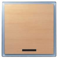


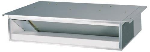


7 Part 1 General Information 2. External Appearance Wall mounted ART COOL ART COOL Mirror 1-way Ceiling cassette 4-way Ceiling concealed duct High static pressure Low static pressure Low static pressure (Slim) Built in Ceiling & floor - 7 -
8 Part 1 General Information 3. Model Number Nomenclature AMN H 07 6 L Q A 0 Serial Number Function A : Basic, L : Nano Plasma + Auto Clean(Wall Mounted) C: Plasma(Ceiling Cassette), G: Low Static Motor ART COOL(DELUXE) Type Front Panel Color B : Blue, D : Wood, M : Meta, R : Mirror, W : White Chassis Name Indoor Unit Type L : Wall Mounted, A : ART COOL D : ART COOL DELUXE, T : Ceiling Cassette B : Ceiling Concealed Duct V : Ceiling & Floor(Convertible) D : D Look (Wall Mounted) Electrical Rating 6 : 1Ø, V, 50Hz G : 220~240V, 50/60Hz Nominal Cooling Capacity in Btu/h Ex) 7,000 Btu/h '07', 18,000 Btu/h '18' Model Type H : Heat Pump C : Cooling Only Type of Airconditioner AMN: Multi system Indoor Unit, R410a Ref. LMN: Multi system Indoor Unit, R22 Ref
9 Part 1 General Information Panel (Cassette, Built in Duct) Category CHASSIS PANEL NAME Remark CST PANEL BUILT IN DUCT TF TC,TC1 TE(family look) TE1(family look) TD(family look) TH(family look) PT-CFA COOLING PT-CFC COOLING + PLASMA PT-HFA HEATING PT-HFC HEATING + PLASMA PT-CCA COOLING PT-CCC COOLING + PLASMA PT-HCA HEATING PT-HCC HEATING + PLASMA PT-HEA HEATING PT-HEC HEATING + PLASMA PT-CEA COOLING PT-CEC COOLING + PLASMA PT-HEA1 HEATING PT-HEC1 HEATING + PLASMA PT-HAD HEATING PT-HDC HEATING + PLASMA PT-CDA COOLING PT-CDC COOLING + PLASMA PT-HDA1 HEATING PT-HDC1 HEATING + PLASMA BP PB-HPA 9K/12K BQ PB-HQA 18K/24K P T - H E A Number Contents 1, 2 Panel for Cassette 3-4 Cooling/Heatpump 5 Chassis Name 6 Function 5. Chassis Name Chassis Abbrevation TC C TB B TD D TE E TF F TH H TJ J BP P BQ Q 6. Function Function Basic A B Plasma Filter C D Elevation Grille E Elevation Grille + Plasma Filter F TE/TB/TD Before 2003 : Basic 0 TE/TD Before 2003 : Plasma Filter 1-9 -
10 Part 2 Functions & Controls 1. List of Functions & Controls Air flow Auto swing (left & right) Auto swing (up & down) Chaos swing (up/down) Air flow step Chaos wind (auto wind) Jet Cool Mode Operation Swirl wind Swing Air purifying PLASMA Air Purifying System Installation Functions E.S.P. (External Static Pressure) Setting High Ceiling operation Reliability Hot start Self-diagnosis Function Soft dry operation Convenience Functions & Controls Auto cleaning operation Auto Operation (Fuzzy Operation) Auto restart Opeartion Child Lock Function Forced operation Group Control Sleep Timer Operation Timer(On/Off) Weekly Program Two Thermistor Control Special Function & KIT Zone Controller Low Ambient control Space Control Auto Elevation Grille Defrost Control(Heating)
11 Part 2 Functions & Controls 1. List of Functions & Controls Category Function Description Remark Airflow Air purifying Installation Reliability Convenience Auto swing (left & right) Auto swing (up & down) Chaos swing (up & down) Airflow steps (fan/cool/heat) Chaos wind (auto wind) Jet cool (Power wind) Swirl wind Swing Deodorizing filter Plasma air purifier Pre-filter (washable/anti-fungus) Drain pump E.S.P. control Electric heater (operation) High ceiling operation Hot start Self diagnosis Soft dry operation Auto changeover Auto clean Auto operation (artificial intelligence) Auto restart operation Child lock Forced operation Group control Sleep mode Timer (on/off) Timer (weekly) Two thermistor control Horizontal Airflow Direction control Vertical Airflow Direction control Vertical Airflow Direction control Indoor Fan speed Control Indoor Fan speed Control by chaos pattern Powerful cooling mode Distribute & stir the Air inside. Air filtration using Deodorizing filter Air filtration using plasma filter Air filtration using pre-filter Drain water pump Changeable External Static Pressure Electric heater Function to Control the Air Volume by Ceiling Height To prevent cold wind blow on heating mode start Error code displays Dehumidification Cooling mode is automatically changed to heating mode and vice verse After cooling operation, this function makes the evaporator dry Air volume & set temp. are automatically selected for comfort on Cooling/Heating mode When power returns after a power failure, unit restarts in the previous operating mode Protect the unit operation without approval Operation without remote controller Where several products are linked, one specific control device can control a specific number of products. Air volume & set temp. are automatically changed for comfortable sleep Operation by Timer setting Operation by weekly reservation Option to control temperature by referring thermistor in the Indoor unit or the LCD wired remote. Standard wired remote controller Standard wired remote controller Deluxe wired remote controller Deluxe wired remote controller Simple wired remote controller Simple wired remote controller Individual control Wired remote Controller Wired remote controller (for hotel use) (for hotel use) Wireless remote controller Wireless remote controller (simple) (simple) Wireless LCD remote control Wireless LCD remote control General central controller General central controller CAC network (Non LGAP) function Dry contact Dry contact
12 Part 2 Functions & Controls Category Function Description Remark Network Solution (LGAP) Network Solution (LGAP) CAC network PDI PDI (power distribution indicator) function (Power Distribution Indicator) PI 485 Network control using PI 485 (Internet) Zone control control the operation of the Air conditioning unit where each zone Special function For operation at low temp. & kit Vanes angle can be controlled by pair. Grille is automatically down to clean Condenser frost prevention Detect high pressure for safety Detect low pressure for safety Functions for Misconnection prevention for three phase outdoor For overload prevention Low ambient operation Space Control Auto Elevation Defrost / Deicing High pressure switch Low pressure switch Phase protection Restart delay (3-minutes) Self diagnosis Soft start Test function Error code displays Soft start for compressor Test operation Notes: The Exploded View part has the particular Function table for each model
13 Part 2 Functions & Controls 2. Air flow 2.1 Auto swing (left & right) By the horizontal airflow direction control key input, the left/right louver automatically operates with the auto swing or it is fixed to the desired direction. Left 110 ~ 120 Right 2.2 Auto swing (up & down) By the auto swing key input, the upper/lower vane automatically operates with the auto swing or it is fixed to the desired direction. Close 110 ~ 120 Open 2.3 Chaos swing (up/down) By the Chaos swing key input, the upper/lower vane automatically operates with the chaos swing or it is fixed to the desired direction. CLOSED Mode9 Mode8 Mode7 Mode6 Mode5 Mode4 Mode3 Mode2 7~8 110~120 OPEN NOTE: Some Models are different by swing width and swing pattern
14 Part 2 Functions & Controls 2.4 Air flow step Indoor fan motor control have 6 steps. Air volume is controlled "SH", "H", "Med", Low" by remote controller. "LL" step is selected automatically in Hot start operation. Step LL L M H SH Auto Discription Very low, In heating mode Low Med High Super high Chaos wind 2.5 Chaos wind (auto wind) When "Auto" step selected and then operated, the high, medium, or low speed of the airflow mode is operated for 2~15 sec. randomly by the Chaos Simulation 2.6 Jet Cool Mode Operation While in heating mode or Fuzzy operation, the Jet Cool key cannot be input. When it is input while in the other mode operation (cooling, dehumidification, ventilation), the Jet Cool mode is operated. In the Jet Cool mode, the indoor fan is operated at super-high speed for 30 min. at cooling mode operation. In the Jet Cool mode operation, the room temperature is controlled to the setting temperature, 18 C. When the sleep timer mode is input while in the Jet Cool mode operation, the Jet Cool mode has the priority. When the Jet Cool key is input, the upper/lower vanes are reset to those of the initial cooling mode and then operated in order that the air outflow could reach further. 2.7 Swirl wind Swing It is the function for comfort cooling/heating operation. The diagonal two louvers are opened the more larger than the other louvers. After one minute, it is opposite. Vane 2 Vane 1 Vane 3 Comparison of Air Flow Types 4-Open (conventional) Swirl Swing (New) Vane

15 Part 2 Functions & Controls 3. Air purifying 3.1 PLASMA Air Purifying System The PLASMA Air Purifying System not only removes microscopic contaminants and dust, but also removes house mites, pollen, and pet fur to help prevent allergic diseases like asthma. This filter that can be used over and over again by simply washing with water. Dust particles Ionizer Dust electrode discharge Photo-Catalyst Coated Mesh +4.8KV discharge + Polluted Air Purified fresh Air + Odour Odour molecule Generating plasma
16 Part 2 Functions & Controls 4. Installation Functions 4.1 E.S.P. (External Static Pressure) Setting Open the rear cover of the wired remote-controller to set the mode Select one of three selectable modes as follows. Without Zone System 1. Position V-H, F-H This position sets the maximum E.S.P. as a default set. 2. Position V-L This position sets the minimum E.S.P. as a default set. With Zone System 1. Position V-H Maximum E.S.P. setting & Fan speed is varied according to the state of dampers by micom. 2. Position F-H Maximum E.S.P. setting & Fan speed doesn't vary according to the opening & closing of dampers. 3. Position V-L Minimum E.S.P setting & Fan speed is varied according to the state of dampers by micom. * Maximum : 8mmAq Minimum : 0mmAq Move the slide switch to set position. TH R13H R12H OP5R16H OP4 CO1H V-H F-H V-L R14H OP3 OP2 OP1 R19H SW TH R11H REMO MAIN 2TH OP7 R18H R17H OP6 LO STAND HI R03S C070 R04S R01S R15H Slide switch for ceiling height SW HIGH R02S Close the rear cover and check if it works normally
17 Part 2 Functions & Controls How to Set E.S.P? Procedure of RPM change: Ex) External Static pressure is 4mmAq for Model 36K. To protect the unit, compressor is designed to be off during E.S.P. setting. 1 Push the"on/off"button. The unit will start. AUTO SWING OPERATION SET TEMP FAN SPEED SUB FUNCTION Room Temp HI AUTO Heater Preheat MED JET Defrost Humidify LO Filter Out door Time ZONE Operation unit Program set Set no. Time Push the "Timer" and "Wind" button simultaneously for more then 3 seconds. Timer AUTO SWING Operation unit OPERATION SET TEMP Room Temp Time Program set FAN SPEED HI MED LO ZONE SUB FUNCTION AUTO Heater Preheat JET Defrost Humidify Filter Out door Set no. Time Push the "Up" of "Down" button for E.S.P adjustment. And, adjust the number which you want.(in this example, the number is "225". Refer to the table 1 on the next page.) AUTO SWING Operation unit OPERATION SET TEMP Room Temp Time Program set FAN SPEED SUB FUNCTION HI AUTO Heater Preheat MED JET Defrost Humidify LO Filter Out door ZONE 2 Set no. Time Note: The range of selection is from 1~254. Since, the display is two Digit only. If the range selection is above 100 then the third digit will appear in the screen as shown. 4 Shift the fan speed mode by pressing the fan speed button. And then, Adjust numbers of next steps by repeating the stage 3. (In this example, the numbers are "237" and "243" respectly) 5 Push the "Timer" and "Wind" button simultaneously for more than 3 seconds. Then, Wind Data is memorized by the EEPROM of the main PCB. Timer AUTO SWING OPERATION SET TEMP FAN SPEED SUB FUNCTION Room Temp HI AUTO Heater Preheat MED JET Defrost Humidify LO Filter Out door Time ZONE Operation unit Program set Set no. Time


18 Part 2 Functions & Controls 4.2 High Ceiling operation Function to Control the Air Volume by Ceiling Height Control of the air intensity has been made possible by employing a height-control algorithm for the interior fan. According to the height of the installation, it provides variability of indoor fan motor rpm. If the height of installation is low then you can adjust low rpm of indoor fan motor. On the other hand if the height of the installation is high you can adjust high rpm of indoor fan motor. Selection of speed can be done by slide switch at the back of the LCD wired remote. Installation on the normal-height ceiling installation on the higher ceiling Elevation Choice Conditions of Release Low Standard Hi - When the elevation is low: lower than 2.4m in height. - Operate the device at one level lower than the standard level. - When the elevation is standard: about 2.7m in height. - Operate the device at the standard air flow level. - When the elevation is high: higher than 3.0m in height. - Operate the device at one level higher than the standard level
19 Part 2 Functions & Controls 5. Reliability 5.1 Hot start When heating is started, the indoor fan is stopped or very slow to prevent the cold air carry out When the temp. of heat exchanger reach 30 C(model by model), indoor fan is started. 5.2 Self-diagnosis Function The air conditioner installed can self-diagnosed its error status and then transmits the result to the central control. Therefore, a rapid countermeasure against failure of the air conditioner allows easy management and increases the usage life of air conditioner. Refer to trouble shooting guide. 5.3 Soft dry operation When the dehumidification operation input by the remote control is received, the intake air temperature is detected and the setting temp is automatically set according to the intake air temperature. Intake air Temp. Setting Temp. 26 C intake air temp. 25 C 24 C intake air temp.< 26 C intake air temp. -1 C 22 C intake air temp. < 24 C intake air temp C 18 C intake air temp. < 22 C intake air temp. intake air temp. < 18 C 18 C While compressor off, the indoor fan repeats low airflow speed and stop. While the intake air temp is between compressor on temp. and compressor off temp., 10-min dehumidification operation and 4-min compressor off repeat. Compressor ON Temp. Setting Temp+0.5 C Compressor OFF Temp. Setting Temp-0.5 C In 10-min dehumidification operation, the indoor fan operates with the low airflow speed
20 Part 2 Functions & Controls 6. Convenience Functions & Controls 6.1 Auto cleaning operation Function used to perform Self Cleaning to prevent the Unit from Fungus and bad odor. Used after the Cooling Operation before turning the unit off, clean the Evaporator and keep it dry for the next operation. The function is easy to operate as it is accessed through the Remote controller. Unit Operation ON OFF (Heat Pump) Indoor Fan ON OFF Setting step L Low OFF ON Comp. OFF Setting step 13~14 minutes 1 minute 2~3 minutes Unit Operation ON OFF (Cooling Only) Indoor Fan ON OFF Setting step L Low OFF ON Comp. OFF Setting step
21 6.2 Auto Operation (Fuzzy Operation) Part 2 Functions & Controls When any of operation mode is not selected like the moment of the power on or when 3 hrs has passed since the operation off, the operation mode is selected. When determining the operation mode, the compressor, the outdoor fan, and the 4 way valve are off and only the indoor fan is operated for 15 seconds. Then an operation mode is selected according to the intake air temp at that moment as follows. 24 C Inatake Air Temp Fuzzy Operation for Cooling 21 C Inatake Air Temp < 24 C Fuzzy Operation for Dehumidification Inatake Air Temp < 21 C Fuzzy Operation for Heating If any of the operation modes among cooling / dehumidification / heating mode operations is carried out for 10 sec or longer before Fuzzy operation, the mode before Fuzzy operation is operated Fuzzy Operation for Cooling According to the setting temperature selected by Fuzzy rule, when the intake air temp is 0.5 C or more below the setting temp, the compressor is turned off. When 0.5 C or more above the setting temp, the compressor is turned on. Compressor ON Temp Setting Temp C Compressor OFF Temp Setting Temp C At the beginning of Fuzzy mode operation, the setting temperature is automatically selected according to the intake air temp at that time. 26 C Intake Air Temp 25 C 24 C Intake Air Temp<26 C Intake Air Temp + 1 C 22 C Intake Air Temp<24 C Intake Air Temp C 18 C Intake Air Temp<22 C Intake Air Temp Intake Air Temp<18 C 18 C When the Fuzzy key (Temperature Control key) is input after the initial setting temperature is selected, the Fuzzy key value and the intake air temperature at that time are compared to select the setting temperature automatically according to the Fuzzy rule. While in Fuzzy operation, the airflow speed of the indoor fan is automatically selected according to the temperature Fuzzy Operation for Dehumidification According to the setting temperature selected by Fuzzy rule, when the intake air temp is 0.5 C or more below the setting temp, the compressor is turned off. When 0.5 C or more above the setting temp, the compressor is turned on. Compressor ON Temp Setting Temp C Compressor OFF Temp Setting Temp+0.5 C At the beginning of Fuzzy mode operation, the setting temperature is automatically selected according to the intake air temp at that time. 26 C Intake Air Temp 25 C 24 C Intake Air Temp<26 C Intake Air Temp+1 C 22 C Intake Air Temp<24 C Intake Air Temp+0.5 C 18 C Intake Air Temp<22 C Intake Air Temp Intake Air Temp<18 C 18 C When the Fuzzy key (Temperature Control key) is input after the initial setting temperature is selected, the Fuzzy key value and the intake air temperature at that time are compared to select the setting temperature automatically according to the Fuzzy rule. While in Fuzzy operation, the airflow speed of the indoor fan repeats the low airflow speed or pause as in dehumidification operation
22 Part 2 Functions & Controls Fuzzy Operation for Heating According to the setting temperature selected by Fuzzy rule, when the intake air temp is 3 C or more above the setting temp, the compressor is turned off. When below the setting temp, the compressor is turned on. Compressor ON Temp Setting Temp Compressor OFF Temp Setting Temp + 3 C At the beginning of Fuzzy mode operation, the setting temperature is automatically selected according to the intake air temp at that time. 20 C Intake Air Temp Intake Air Temp C Intake Air Temp<20 C 20 C When the Fuzzy key (Temperature Control key) is input after the initial setting temperature is selected, the Fuzzy key value and the intake air temperature at that time are compared to select the setting temperature automatically according to the Fuzzy rule. While in Fuzzy operation, the airflow speed of the indoor fan is set to the high or the medium according to the intake air temperature and the setting temperature. Notes: The Temp. of Comp. Turn ON and OFF is different in heating mode and fuzzy operation for heating. Please, refer page Auto restart Operation Whenever there is electricity failure to the unit, and after resumption of the power, unit will start in the same mode prior to the power failure. Memorized condition are on / off condition, operating mode (cooling/ heating), set temperature and fan speed. The unit will memorize the above conditions and start with same memorized condition
23 6.4 Child Lock Function Part 2 Functions & Controls This function prevents children or others from tampering with the control buttons on the unit. It is then controlled by the remote controller. All the buttons on indoor display panel will blocked. The unit will be controlled only by remote controller. The function is used to restrict children to not to use the air conditioner carelessly.(cl is an abbreviated form of Child Lock.) AUTO SWING OPERATION SET TEMP FAN SPEED SUB FUNCTION Room Temp HI MED AUTO Heater Preheat Defrost Humidify LO JET Filter Out door Time ZONE Timer On Off Operation unit Program set Set no. Time Timer Program Hour Cancel Week Min 2ndF Holiday Set/Clr RESET PLASMA Function setup 1 If you press the preset and minute setup button for 3 seconds at the same time, the operation condition switches to the child lock function and will be indicated as "CL" on the indication monitor. At that time, remote control doesn't switch to the selected mode and "CL" appears on the indication monitor for 3 seconds if you press another button. However, it normally performs the actions of the room temperature indication function and wireless remote control. Timer Program Hour Cancel Week Min Holiday Function cancel 1 Press the preset and minute setup button over 3 seconds at the same time. In that case, the child lock function cancels and will be indicated as the previous condition. Set/Clr 6.5 Forced operation To operate the appliance by force in case when the remote control is lost, the forced operation selection switch is on the main unit of the appliance, and operate the appliance in the standard conditions. The operating condition is set according to the outdoor temp. and intake air temperature as follows. Indoor temp. Operating Mode Setting temp. Setting speed of indoor fan over 24 C Cooling 22 C 21~24 C Healthy Dehumidification 22 C High speed below 21 C Heating 22 C The unit select the last operation mode in 3 hours. Operating procedures when the remote control can't be used is as follows : - The operation will be started if the ON/OFF button is pressed. - If you want to stop operation, re-press the button
24 Part 2 Functions & Controls 6.6 Group Control Operation Summary Where several products are linked, one specific control device can control a specific number of products Specific Operation Connecting line is linked to each of the indoor equipments for communication. A specific control device is connected to each of them and this control device can control the same function. Group control function is enabled by cutting an optional jump wire in the wired remote control. At this time, the main system will not respond in order to prevent data collision. While executing group control command, use the random data(0-3minutes) in the main body of indoor equipment for limiting starting current. Control device can control up to 16 indoor equipments
25 AUTO SWING OPERATION SET TEMP FAN SPEED SUB FUNCTION Room Temp HI AUTO Heater Preheat MED JET Defrost Humidify LO Filter Out door Time ZONE Timer Operation unit Program set On Off Set no. Time Part 2 Functions & Controls Group Control( Wiring) You can use a group control operation after connecting the brown and yellow wire of each air-conditioner. Remove the resistor "OP 7" in remote controller. It operates maximum 16 Units by only one Wired Remote Controller, and each Unit starts sequentially to prevent overcurrent. Wiring design Main PCB RED(12V) YL(SIGNAL) BR(GND) Indoor Unit 1 Terminal(Local Supply) Block Connector RED(12V) YL(SIGNAL) BR(GND) Main PCB #1 YL(SIGNAL) BR(GND) Indoor Unit 2 Terminal(Local Supply) Block Connector YL(SIGNAL) BR(GND) Main PCB #2... YL(SIGNAL) BR(GND) Indoor Unit 16 Terminal(Local Supply) Block Connector YL(SIGNAL) BR(GND) Main PCB #16... Connecting Cable(Local Supply) Wired Remote Controller Slide Switch OP7 Remote Controller PCB Features Use Only One Wired Remote Controller with several air conditioners(max. 16 Units) Random starting to prevent overcurrent. Be careful not to exchange the color of wires. The maximum length of connecting wire should be below 200m(25Ω) on connecting each units. Use a wire more than 0.5mm2-25 -
 hr> is input by the remote control while in appliance operation, the operation of the appliance stops.")
26 Part 2 Functions & Controls 6.7 Sleep Timer Operation When the sleep time is reached after <1,2,3,4,5,6,7,0(cancel) hr> is input by the remote control while in appliance operation, the operation of the appliance stops. While the appliance is on pause, the sleep timer mode cannot be input. While in cooling mode operation, 30 min later since the start of the sleep timer, the setting temperature increases by 1 C. After another 30 min elapse, it increases by 1 C again. When the sleep timer mode is input while in cooling cycle mode, the airflow speed of the indoor fan is set to the low. When the sleep timer mode is input while in heating cycle mode, the airflow speed of the indoor fan is set to the medium. 6.8 Timer(On/Off) On-Timer Operation When the set time is reached after the time is input by the remote control, the appliance starts to operate. The timer LED is on when the on-timer is input. It is off when the time set by the timer is reached. If the appliance is operating at the time set by the timer, the operation continues. While in Fuzzy operation, the airflow speed of the indoor fan is automatically selected according to the temperature Off-Timer Operation When the set time is reached after the time is input by the remote control, the appliance stops operating. The timer LED is on when the off-timer is input. It is off when the time set by the timer is reached. If the appliance is on pause at the time set by the timer, the pause continues. 6.9 Weekly Program If necessary, an operator can make an On/Off reservation of the product for a period of one week. - On/Off schedule of operation for a period of ONE week. No need to turn the unit On/OFF manually during working days. On/Off time is scheduled in micom of the wired remote control. Operation Time Table (Example) Setting Temp. Mon Tue Wed Thu Fri Sat Sun 25 C 25 C 25 C 25 C 25 C On 09:00 08:00 09:00 08:00 09:00 OFF Off 12:00 17:00 12:00 12:00 12:
27 6.10 Two Thermistor Control Part 2 Functions & Controls There may be a significant difference between temperature taken at the installed product indoor temperature. Two thermistor control provides option to control temperature by referring any of the two temperatures. With help of the slide switch at the back of the wired remote controller, selection of the thermistor for controlling the unit can be One thermistor is in the Indoor unit & the one is in the LCD wired remote. Two Thermistor System Open the rear cover of the wired remote-controller to set the mode Select one of three selectable modes as follows. Position 1: The room temperature is controlled by the thermistor of the main body. Position 2: The room themperature is controlled by the thermistor of the wired remote-controller, control the temperature according to the position of wired remote-controller. Position 3: The room temperature is controlled by lower temperature between the temperature of main body and of remote-controller sensor Move the slide switch to set position. Room Temp. sensor Slide switch for 2 Thermistor TH R13H R12H OP5R16H OP4 CO1H Position 2 Position 1 Position 3 REMO MAIN 2TH R14H OP3 OP2 OP1 R19H SW TH R11H REMO MAIN 2TH OP7 R18H R17H OP6 LO STAND HI R03S C070 R04S R01S R15H SW HIGH R02S Close the rear cover and check if it works normally. Select the position after counselling with a customer. In case of cooling mode, room temperature is controlled by the main body sensor. To control the room temperature by a wired remote controller, install controller(room temp. sensor) to sense the temperature more accurately. Maunfactured in the position
 has a separate thermostat and damper motor, your Air")

28 Part 2 Functions & Controls 7. Special Function & KIT 7.1 Zone Controller This feature can be used to control the operation of the Air Conditioning Unit where each zone (maximum of 4 zones) has a separate thermostat and damper motor, your Air Conditioning Room1 Thermostat Room2 Thermostat Damper Motor Damper Motor Damper Motor Damper Motor Zone control sub PCB Room3 Thermostat Room4 Thermostat ABZCA 7.2 Low Ambient control This Function is for cooling operating in outdoor low temperature. If outdoor temperature drops below certain temperature, liquid back is prevented by reducing outdoor fan speed. It can prevent frosting of evaporator and keep cooling operation Outdoor pipe T2 C T1 C Outdoor Fan Speed Setting Speed Off Setting Speed Off Setting Speed


 Ascend Descend Stop ➂ Instruction manual ➃ Remote Controller for lift grill How to Use Remote Controller As for operation of Remote Controller, use it by directing the transmitter part of")
29 Part 2 Functions & Controls 7.3 Space control Vanes angle can be controlled by pair, considering its installation environment. For example direct drafts can be annoying, leading to discomfort and reduced productivity vane control helps to eliminate this problem. Easily controlled by wired remote control. Air Flow can be controlled easily regarding any space environment. 7.4 Auto Elevation Grille Auto Elevation Grille is automatically down to height of max. 3.1 m. So it enables to install the Indoor unit at high ceiling space. And Auto Elevation Grille makes you cleaning the filter easily. ELEVATION GRILL (REMOTE CONTROLLER_Accessory) Signal transmitter Main Components of Lift Grill ➀ Lift grill front panel assembly ➁ Bolts for installation (4 EA, P/No. 3A00255K) Ascend Descend Stop ➂ Instruction manual ➃ Remote Controller for lift grill How to Use Remote Controller As for operation of Remote Controller, use it by directing the transmitter part of Remote Controller to the receiver part of front panel directly under front panel. Do not drop it down or into water. Or else there is worry about trouble failure. Do not press hard the Remote Controller button with nail (ballpoint pen or other sharp substance). Or else there is worry about trouble failure. In case when obstacle such as curtain hides the signal reception part of receiver in between the space interval, Remote Controller operation is infeasible
30 Part 2 Functions & Controls How to Operate the Lift Grill Always stop the air conditioner operation for safety before operating lift grill. Take heed _ there is worry about dust fall etc. when suction grill descends. In case when the set automatic stop distance goes wrong, check the set value of operation panel and confirm if there is neither obstacle nor mankind. When you are not to remove obstacle, stop the operation before touching the obstacle. 1. Stop the Air Conditioner Operation Automatic Stop Distance of Grill 2. Descend the Suction Grill - Depress the down button( ). Then suction grill descends and stops automatically at a certain distance. - You may stop it at wanted distance point by depressing the stop button ( ) when descending. 3. Raise the Suction Grill - Depress the up button( ). Then suction grill goes up and enters into the front panel. Automatic stop distance 4. Stop the Suction Grill during Rising - Depress the stop button( ). Make use of this when you want to stop it at your wished position. Ceiling height Low Medium (Height: 3~4 m) High Automatic stop distance 1.5±0.5m 2.5±0.5 m 3.5±0.5m If you want to change automatic distance setting, consult with your sale agency. 7.5 Defrost Control (Heating) Defrost operation is controlled by timer and sensing temperature of outdoor pipe. The first defrost starts only when the outdoor pipe temperature falls below -6 C after starting of heating operation and more than 4 minutes operation of compressor. Defrost ends after 12 minutes passed from starting of defrost operation when the outdoor rises over 15 C even before 12 minutes. The second defrost starts only when the outdoor pipe temperature falls below 6 C after from ending of the first defrost and more than 4 minutes operation of compressor
31 3. Trouble Shooting Self-diagnosis function
32 Self-diagnosis function Self-diagnosis function Self-diagnosis Function 1. Error Indicator (Indoor) The function is to self-diagnosis air conditioner and express the troubles if there is any trouble. Error mark is displayed on display window of indoor units and wired-remote controller, and LED of outdoor unit control board. If more than two troubles occur simultaneously, lower number of error code is first displayed. After error occurs, if error is released, error LED is also released simultaneously. 1 digit 10 digit Ex) Error 21 (DC Peak) 2 Times 2 Times 2 Times 10 digit LED 1 Sec. 1 Sec. 1 Sec. 1 Time 1 Time 1 Time 1 digit LED 2 Sec. 2 Sec. 2. Indoor Error Error code Description INV TPS LED 1 (Red) LED 2 (Green) Indoor Status 00 No Error ON 01 Indoor Room themistor error 1time OFF 02 Indoor in-piping sensor error 2times OFF 03 Remote controller error 3times OFF 04 Drain Pump error 4times OFF 05 Communcation error between in and out 5times OFF 06 Indoor Out-Piping sensor error 6times OFF 07 Differnt mode operation 7times OFF 09 EEPROM Check sum (indoor) 9times OFF 10 BLDC motor fan lock (indoor) 10times OFF
33 Self-diagnosis function 3. Check code Trouble shooting CH01, CH02, CH06 Display code Title Cause of error Check point & Normal condition 01 Indoor air sensor Connector connection error Faulty PCB Faulty sensor (Open / Short) Normal resistor : 10KΩ/ at 25 C (Unplugged) Normal voltage : 2.5Vdc / at 25 C(Plugged) Refer to sensor resistance table. 02 Indoor inlet pipe sensor Connector connection error Faulty PCB Faulty sensor (Open / Short) Normal resistor : 5KΩ/ at 25 C(Unplugged) Normal voltage : 2.5Vdc / at 25 C(Plugged) Refer to sensor resistance table. 06 Indoor outlet pipe sensor Connector connection error Faulty PCB Faulty sensor (Open / Short) Normal resistor : 5KΩ/ at 25 C(Unplugged) Normal voltage : 2.5Vdc / at 25 C(Plugged) Refer to sensor resistance table. Check Flow Chart Unplug the sensor on Indoor unit PCB Estimate the Voltage of each sensor. Check the Connector connection Is the voltage of the sensor 2.5Vdc at 25 C No Correct connection Is it normal? No Correct connection Yes Repair or Change the PCB. Yes Unplugged Plugged Estimate the resistance of each sensor. Is the resistance of the sensor 10Ω / 5kΩ at 25 C? No Correct connection 10kΩ 2.5Vdc Yes Ω V Plug the sensor on Indoor unit PCB Check the resistance Check the voltage
 Connector connection error Faulty PCB / Remote")
34 Self-diagnosis function 4. Check code Trouble shooting CH03 Display code Title Cause of error Check point & Normal condition 03 Communication Error (Wired remote controller) Connector connection error Faulty PCB / Remote controller Connection wire break Connection of wire Main PCB Volt. DC12V Noise interference Check Flow Chart Check the wire connection(open / Short / Miswirring) CN-REMO Is it normal? Yes No Correct connection Or change connection wire Is the soldering state of connector is normal? Yes Check the volt. of main PCB power source. (DC 12V,DC 5V) No Re-soldering component Or change the PCB Wired R/C S 12V GND (YL) (RD) (BR) Indoor Unit 12V S GND (RD) (YL) (BR) Is it normal? Yes Check the installation of wired remote controller. (Noise interference) No Correct connection Or change the PCB 12Vdc V 12Vdc V Is it normal? No Adjust the state of installation Check the Volt. Check the Volt
 Water over flow The connection of wire (Drain pump/ Float switch) Drain pump power input. (220V) Drain tube installation. Indoor unit installation.")
35 Self-diagnosis function 5. Check code Trouble shooting CH04 Display code 04 Title Cause of error Check point & Normal condition Drain pump / Float switch Float switch open. (Normal : short) Water over flow The connection of wire (Drain pump/ Float switch) Drain pump power input. (220V) Drain tube installation. Indoor unit installation. (Inclination) Check Flow Chart Check the level of water (Float moves top position) Is it normal? No Check Drain Pump CN-Float CN-Float Yes Is the float switch clean? No Clean float switch Drain pump check Yes Check the wire connection (Open, Soldered poorly) Is it normal? Yes Is the resistance of f loat switch normal (short)? No Correct connection Or re-soldering PCB No Change the float switch Check the wire connection (Open, Soldered poorly) Is it normal? Yes Is the resistance of Drain Pump? Normal ( about 400Ω )? Yes No Correct connection Or re-soldering PCB No Change the Drain Pump Is the drain pump clean? No Clean drain pump Yes Check drain tube installation
36 Self-diagnosis function Error No. Error Type Error Point Main Reasons 1. Transmission cable is not connected 05 Indoor & Outdoor unit transmission error No signal transmission between indoor & outdoor units. 2. Short circuit of transmission cable 3. Indoor unit transmission circuit fault 4. Outdoor unit transmission circuit fault 5. Not enough distance between power and transmission cable? Error No. Error Type Error Point Main Reasons 06 Indoor unit outlet pipe temperature sensor error Indoor unit outlet pipe temperature sensor open or short Refer to CH02 Error No. Error Type Error Point Main Reasons 07 All Indoor units are not running in same mode The Indoor units started later are operated in different mode from earlier one. 1. Indoor units are in different mode 2. PCB fault
37 Self-diagnosis function 6. Check code Trouble shooting CH09, CH10 Display code Title Cause of error Check point & Normal condition 09 EEPROM Check sum (Indoor) Check sum error Check the poor soldering. Change PCB 10 BLDC motor fan lock (Indoor) Fan motor break down Fan motor & PCB poor contact Obstruction to the fan Check the indoor fan motor. Check the connection status between PCB and fan motor. Check Flow Chart Check the indoor fan motor. (Fan is locked by obstruction) Is it normal? Yes No Remove obstruction Check the connection status between PCB and fan motor Is it normal? Yes No Correct connection Or re-soldering PCB Check the DC Motor signal Is it normal? No Change Indoor Motor
38 P/NO : MFL APRIL. 2008
Single "A" Air Conditioner SVC MANUAL(General)
") Internal Use Only http://biz.lgservice.com Single "A" Air Conditioner SVC MANUAL(General) MODEL : Single "A"-Inverter Type CAUTION Before Servicing the unit, read the safety precautions in General SVC
Internal Use Only http://biz.lgservice.com Single "A" Air Conditioner SVC MANUAL(General) MODEL : Single "A"-Inverter Type CAUTION Before Servicing the unit, read the safety precautions in General SVC
Single Zone Air Conditioner SVC MANUAL(General)
") Single Zone Air Conditioner SVC MANUAL(General) CAUTION Before Servicing the unit, read the safety precautions in General SVC manual. Only for authorized service personnel. 960-914-06 Air Conditioner Service
Single Zone Air Conditioner SVC MANUAL(General) CAUTION Before Servicing the unit, read the safety precautions in General SVC manual. Only for authorized service personnel. 960-914-06 Air Conditioner Service
Weekly Wired Remote Controller
 LG LG Weekly Wired Remote Controller Owner's & Installation Manual Models: PVRCUSZ0 IMPORTANT Please read this installation manual completely before installing the product. Installation work must be performed
Weekly Wired Remote Controller
 LG LG Weekly Wired Remote Controller Owner's & Installation Manual Models: PCRCUSZ0 PDRCUSZ0 IMPORTANT Please read this installation manual completely before installing the product. Installation work must
AIR CONDITIONER OWNER S MANUAL ENGLISH FRANÇAIS ESPAÑOL
 OWNER S MANUAL AIR CONDITIONER Please read this manual carefully before operating your set and retain it for future reference. TYPE : FLOOR STANDING ENGLISH FRANÇAIS ITALIANO ESPAÑOL ESPAÑOL DEUTSCH P/NO
New Wide Wired Remote Controller
 LG LG New Wide Wired Remote Controller Owner's & Installation Manual Models: PQRCVSL0 PQRCVSL0QW IMPORTANT Please read this owner's & installation manual completely before installing the product. Installation
LG Concealed Duct Air Conditioner OWNER'S MANUAL
 Visit us at http://www.lgservice.com LG Concealed Duct Air Conditioner OWNER'S MANUAL LG Dear Owner Thank you for installing LG Air Conditioner. Your best choice guarantees you a great performance and
LG Cassette Multi Type Air Conditioner
 LG Cassette Multi Type Air Conditioner OWNER'S MANUAL IMPORTANT LG Please read through this manual. It contains valuable information about your air conditioner. This manual may help save time and money
SIMPLE WIRED REMOTE CONTROLLER
 OWNER S & INSTALLATION MANUAL SIMPLE WIRED REMOTE CONTROLLER Please read this manual carefully before operating your set and retain it for future reference. ENGLISH ITALIANO ESPAÑOL FRANCAIS DEUTSCH PORTUGUESE
Indoor Unit (2 Series)
") Indoor Unit (2 Series) Type: Ceiling Concealed Duct- High Static LG ENGLISH FRANÇAIS ESPAÑOL IMPORTANT Please read this owner's manual carefully and thoroughly before installing and operating your room
Indoor Unit (2 Series) Type: Ceiling Concealed Duct- High Static LG ENGLISH FRANÇAIS ESPAÑOL IMPORTANT Please read this owner's manual carefully and thoroughly before installing and operating your room
HEAT CONTROLLER, INC.
 HEAT CONTROLLER, INC. Wall Mounted Mini-Split System Single-Zone Air Conditioning/Heat Pump Service Manual(General) VMC09SB-1/VMH09SB-1 VMC12SB-1/VMH12SB-1 VMC18SB-1/VMH18SB-1 VMC24SB-1/VMH24SB-1 VMC30SB-1/VMH30SB-1
Indoor Unit (2 Series)
") System Indoor Unit (2 Series) OWNER'S MANUAL Type: Wall mounted LG ENGLISH FRANÇAIS ESPAÑOL IMPORTANT Please read this owner's manual carefully and thoroughly before installing and operating your room
System Indoor Unit (2 Series) OWNER'S MANUAL Type: Wall mounted LG ENGLISH FRANÇAIS ESPAÑOL IMPORTANT Please read this owner's manual carefully and thoroughly before installing and operating your room
OWNER S MANUAL. R 410A Ductless Split System Air Conditioner and Heat Pump
 R 410A Ductless Split System Air Conditioner and Heat Pump Models DLC4(A/H) Outdoor Unit, DLF4(A/H) Indoor Unit Sizes 9K, 12K, 18K, 24K, 30K and 36K Please read the operating instructions and safety precautions
R410A. WALL MOUNTEDtype INVERTER SPLIT TYPE ROOM AIR CONDITIONER. Models Indoor unit Outdoor unit AO*G09LTCN AO*G12LTCN AO*G14LTCN
 SERVICE INSTRUCTION SPLIT TYPE ROOM AIR CONDITIONER WALL MOUNTEDtype INVERTER Models Indoor unit Outdoor unit AS*G09LTCB AS*GLTCB AS*G4LTCB AO*G09LTCN AO*GLTCN AO*G4LTCN R40A CONTENTS. DESCRIPTION OF EACH
SPLIT TYPE ROOM AIR CONDITIONER. WALL MOUNTEDtype INVERTER. Models Indoor unit Outdoor unit AOU 9RLFW1 AOU12RLFW1 ASU 9RLF1 ASU12RLF1 R410A
 SERVICE INSTRUCTION SPLIT TYPE ROOM AIR CONDITIONER WALL MOUNTEDtype INVERTER Models Indoor unit Outdoor unit ASU 9RLF ASURLF AOU 9RLFW AOURLFW R40A CONTENTS. DESCRIPTION OF EACH CONTROL OPERATION. COOLING
Part 3 Troubleshooting
 Part Troubleshooting What is in this part? This part contains the following chapters: Chapter See page Troubleshooting 2 Error Codes: Hydro-box 7 Error Codes: Outdoor Units Error Codes: System Malfunctions
SERVICE INSTRUCTION R410A. WALL MOUNTEDtype INVERTER SPLIT TYPE ROOM AIR CONDITIONER. Models Indoor unit Outdoor unit AOU9RLS2H AOU12RLS2H AOU15RLS2H
 SERVICE INSTRUCTION SPLIT TYPE ROOM AIR CONDITIONER WALL MOUNTEDtype INVERTER Models Indoor unit Outdoor unit ASU9RLS ASURLS ASU5RLS AOU9RLSH AOURLSH AOU5RLSH R40A CONTENTS. DESCRIPTION OF EACH CONTROL
R410A. WALL MOUNTEDtype INVERTER SPLIT TYPE ROOM AIR CONDITIONER. Models Indoor unit Outdoor unit AOYG07LEC AOYG09LEC AOYG12LEC AOYG14LEC
 SERVICE INSTRUCTION SPLIT TYPE ROOM AIR CONDITIONER WALL MOUNTEDtype INVERTER Models Indoor unit Outdoor unit ASYG07LECA ASYG09LECA ASYG12LECA ASYG14LECA AOYG07LEC AOYG09LEC AOYG12LEC AOYG14LEC R410A CONTENTS
SERVICE MANUAL MODELS: LB-H1860HL/CL LB-H2460HL/CL LB-G3680HL/CL
 Ceiling Duct Type Air Conditioner SERVICE MANUAL MODELS: LB-H1860HL/CL LB-H2460HL/CL LB-G3680HL/CL Contents Functions...3 Product Specifications (Cooling & Heating)...5 Dimensions...7 Refrigeration Cycle
Multi V Air Conditioner SVC MANUAL(Exploded View)
") Internal Use nly http://biz.lgservice.com Multi V Air Conditioner SVC MANUAL(Exploded View) MDEL : ARNU05GL1G4 ARNU15GL2G4 ARNU07GL1G4 ARNU18GL2G4 ARNU09GL1G4 ARNU21GL3G4 ARNU12GL2G4 ARNU24GL3G4 CAUTIN
Internal Use nly http://biz.lgservice.com Multi V Air Conditioner SVC MANUAL(Exploded View) MDEL : ARNU05GL1G4 ARNU15GL2G4 ARNU07GL1G4 ARNU18GL2G4 ARNU09GL1G4 ARNU21GL3G4 ARNU12GL2G4 ARNU24GL3G4 CAUTIN
OWNER S MANUAL. High-Wall Fan Coil Unit CONTENTS
 OWNER S MANUAL High-Wall Fan Coil Unit Page GENERAL 2,3 OPERATING MODES 2 REMOTE CONTROL 2 OPERATION 3-9 REMOTE CONTROL OPERATION 3 INDOOR UNIT DISPLAY 5 EMERGENCY OPERATION 5 PRESSING THE ON/OFF BUTTON
Owner's Manual TABLE OF CONTENTS
 40MAQ High Wall Ductless System Sizes 09 to 36 Owner's Manual TABLE OF CONTENTS PAGE A NOTE ABOUT SAFETY... 2 GENERAL... 2 PART NAMES... 3 FUNCTION BUTTONS... 4 DISPLAY PANELS... 5 REMOTE CONTROL... 6
Multi V Air Conditioner SVC MANUAL(Exploded View)
") Internal Use nly http://biz.lgservice.com Multi V Air Conditioner SVC MANUAL(Exploded View) MDEL : ARNU09GTL*4 ARNU12GTL*4 ARNU18GTL*4 ARNU24GTL*4 CAUTIN Before Servicing the unit, read the safety precautions
Internal Use nly http://biz.lgservice.com Multi V Air Conditioner SVC MANUAL(Exploded View) MDEL : ARNU09GTL*4 ARNU12GTL*4 ARNU18GTL*4 ARNU24GTL*4 CAUTIN Before Servicing the unit, read the safety precautions
OWNER'S MANUAL R-410A Duct Free Split System Air Conditioner and Heat Pump
 R-10A Duct Free Split System Air Conditioner and Heat Pump Product Family: DFF(A/H)H, DFC(A/H) Please read the operating instructions and safety precautions carefully and thoroughly before installing and
Multi Type Room Air Conditioner
 Multi Type Room Air Conditioner SERVICE MANUAL INDOOR UNIT: AMNN076L/M/NQA0 AMNN096L/M/NQA0 AMNN6L/M/NRA0 AMNN86L/M/NTA0 AMNN46L/M/NTA0 AMNN096APA0 AMNN6APA0 AMNN6TEA0 AMNN86TEA0 AMNN86VBA0 OUTDOOR UNIT:
DC INVERTER MULTI-SYSTEM AIR CONDITIONER
 TECHNICAL & SERVICE MANUAL OUTDOOR UNIT : CU-3KE19NBU CU-4KE24NBU CU-4KE31NBU DC INVERTER MULTI-SYSTEM AIR CONDITIONER Capacity at 0V 19,100 BTU/h,200 BTU/h 30,600 BTU/h Outdoor Model No. CU-3KE19NBU CU-4KE24NBU
SERVICE MANUAL. Inverter Wall Mounted Single Split. MODELS Cooling Only. Heatpump SM-5WM-Y-NA-B1
 SERVICE MANUAL Inverter Wall Mounted Single Split MODELS Cooling Only FTKB09AXVJU FTKB12AXVJU FTKB18AXVJU FTKB24AXVJU FTKN09AXVJU FTKN12AXVJU FTKN18AXVJU FTKN24AXVJU Heatpump FTXB09AXVJU FTXB12AXVJU FTXB18AXVJU
TABLE OF CONTENTS FOR YOUR RECORDS READ THIS MANUAL PRECAUTION. Room Air Conditioner Owner s Manual
 Room Air Conditioner Owner s Manual TABLE OF CONTENTS Safety Precautions... Prior to Operation...6 Operating Instructions...7 Remote Controller...7 Remote Control Operation.8 Additional features...7 Maintenance
SiBE04-808_C. Service Manual. Inverter Pair Wall Mounted Type G-Series. [Applied Models] Inverter Pair : Cooling Only Inverter Pair : Heat Pump
![SiBE04-808_C. Service Manual. Inverter Pair Wall Mounted Type G-Series. [Applied Models] Inverter Pair : Cooling Only Inverter Pair : Heat Pump](/thumbs/88/114609417.jpg "SiBE04-808_C. Service Manual. Inverter Pair Wall Mounted Type G-Series. [Applied Models] Inverter Pair : Cooling Only Inverter Pair : Heat Pump") Service Manual Inverter Pair Wall Mounted Type G-Series [Applied Models] Inverter Pair : Cooling Only Inverter Pair : Heat Pump Inverter Pair Wall Mounted Type G-Series Cooling Only Indoor Unit FTXS20G2V1B
Service Manual Inverter Pair Wall Mounted Type G-Series [Applied Models] Inverter Pair : Cooling Only Inverter Pair : Heat Pump Inverter Pair Wall Mounted Type G-Series Cooling Only Indoor Unit FTXS20G2V1B
SERVICE INSTRUCTION R410A. WALL MOUNTEDtype INVERTER SPLIT TYPE ROOM AIR CONDITIONER. Models Indoor unit Outdoor unit AO*G24LFL AO*G24LFCC AO*G30LFT
 SERVICE INSTRUCTION SPLIT TYPE ROOM AIR CONDITIONER WALL MOUNTEDtype INVERTER Models Indoor unit Outdoor unit AS*G4LFCA AS*G4LFCC AS*G0LFCA AO*G4LFL AO*G4LFCC AO*G0LFT R40A CONTENTS. DESCRIPTION OF EACH
Air Conditioner CONTENTS
 ORDER NO. MAC0509068C2 Air Conditioner CS-F24DD1E5 CU-B24DBE5 CS-F28DD1E5 CU-B28DBE5 CS-F28DD1E5 CU-B28DBE8 CS-F34DD1E5 CU-B34DBE5 CS-F34DD1E5 CU-B34DBE8 CS-F43DD1E5 CU-B43DBE8 CS-F50DD1E5 CU-B50DBE8 CONTENTS
LG Room Air Conditioner OWNER'S MANUAL
 Visit us at http://www.lgservice.com LG Room Air Conditioner OWNER'S MANUAL LG ENGLISH FRANÇAIS ESPAÑOL Dear Owner Thank you for installing LG air conditioner. Your best choice guarantees you a great performance
Multi V Air Conditioner SVC MANUAL(Exploded View)
") Internal Use nly http://biz.lgservice.com Multi V Air Conditioner SVC MANUAL(Exploded View) MDEL : ARNU05GSB*4 ARNU07GSB*4 ARNU09GSB*4 ARNU12GSB*4 ARNU15GSB*4 ARNU18GSC*4 ARNU24GSC*4 CAUTIN Before Servicing
Internal Use nly http://biz.lgservice.com Multi V Air Conditioner SVC MANUAL(Exploded View) MDEL : ARNU05GSB*4 ARNU07GSB*4 ARNU09GSB*4 ARNU12GSB*4 ARNU15GSB*4 ARNU18GSC*4 ARNU24GSC*4 CAUTIN Before Servicing
New Wide Wired Remote Controller
 LG LG New Wide Wired Remote Controller Owner's & Installation Manual Models: PQRCVSL0 PQRCVSL0QW IMPORTANT Please read this owner's & installation manual completely before installing the product. Installation
Multi V Air Conditioner SVC MANUAL(Exploded View)
") Internal Use nly http://biz.lgservice.com Multi V Air Conditioner SVC MANUAL(Exploded View) MDEL : ARNU07GTU*4 ARNU09GTU*4 ARNU12GTU*4 ARNU18GTT*4 ARNU24GTT*4 CAUTIN Before Servicing the unit, read the
Internal Use nly http://biz.lgservice.com Multi V Air Conditioner SVC MANUAL(Exploded View) MDEL : ARNU07GTU*4 ARNU09GTU*4 ARNU12GTU*4 ARNU18GTT*4 ARNU24GTT*4 CAUTIN Before Servicing the unit, read the
LG Convertible-Type Air Conditioner
 LG Convertible-Type Air Conditioner OWNER'S MANUAL IMPORTANT LG Please read through this manual. It contains valuable information about your air conditioner. This manual may help save time and money by
OWNER S MANUAL DLFCAB / DLFCHB / DLFDAB / DLFDHB High Wall Ductless System Sizes 09 36
 OWNER S MANUAL DLFCAB / DLFCHB / DLFDAB / DLFDHB High Wall Ductless System Sizes 09 36 TABLE OF CONTENTS PAGE SAFETY PRECAUTIONS... 2 GENERAL... 2 INDOOR UNIT PART NAMES... 3 REMOTE CONTROL PART NAMES...
(60Hz/R410A) 6CIM0-02B (Replace: 6CIM0-02A)
 6CIM0-02B (Replace: 6CIM0-02A)") (60Hz/R410A) 6CIM0-02B (Replace: 6CIM0-02A) (60Hz/R410A) 6CIM0-02B (Replace: 6CIM0-02A) CONTENTS Part 1 General information Part 2 Product data Part 3 Design and installation Part 4 Special parts 2 Introduction
(60Hz/R410A) 6CIM0-02B (Replace: 6CIM0-02A) (60Hz/R410A) 6CIM0-02B (Replace: 6CIM0-02A) CONTENTS Part 1 General information Part 2 Product data Part 3 Design and installation Part 4 Special parts 2 Introduction
Multi Zone Air Conditioner SVC MANUAL (Exploded View)
") Multi Zone Air Conditioner SVC MANUAL (Exploded View) CAUTIN Before Servicing the unit, read the safety precautions in General SVC manual. nly for authorized service personnel. MDEL: MD12Y3JM 960-920-06
Multi Zone Air Conditioner SVC MANUAL (Exploded View) CAUTIN Before Servicing the unit, read the safety precautions in General SVC manual. nly for authorized service personnel. MDEL: MD12Y3JM 960-920-06
Multi Zone Air Conditioner SVC MANUAL (Exploded View)
") Multi Zone Air Conditioner SVC MANUAL (Exploded View) CAUTIN Before Servicing the unit, read the safety precautions in General SVC manual. nly for authorized service personnel. MDEL: MD18Y3JM 960-920-07
Multi Zone Air Conditioner SVC MANUAL (Exploded View) CAUTIN Before Servicing the unit, read the safety precautions in General SVC manual. nly for authorized service personnel. MDEL: MD18Y3JM 960-920-07
HEAT CONTROLLER, INC.
 HEAT CONTROLLER, INC. Wall Mounted Mini - Split System DMC24DB-1, DMH24DB-1 DMC36TB-1, DMH36TB-1 Dual-Zone, Tri-Zone Air Conditioning / Heat Pump Important Information Please read carefully and thoroughly
Inverter Split-type Room Air Conditioner
 OWNER S MANUAL Inverter Split-type Room Air Conditioner Please read the operating instructions and safety precautions carefully and thoroughly before installing and operating your room air conditioner.
Service Manual. Inverter Pair Floor / Ceiling Suspended Dual Type BA-Series. SiBE05-722_C
 Service Manual Inverter Pair Floor / Ceiling Suspended Dual Type BA-Series [Applied Models] Inverter Pair : Cooling Only Inverter Pair : Heat Pump Inverter Pair Floor / Ceiling Suspended Dual Type BA-Series
Service Manual. Room Air Conditioner Split Wall-Mounted Type. Applies to: HSG-09HRN1 HSG-12HRN1 HSG-18HRN1 HSG-24HRN1
 Service Manual Room Air Conditioner Split Wall-Mounted Type Applies to: HSG-09CRN1 HSG-12CRN1 HSG-18CRN1 HSG-24CRN1 HSG-09HRN1 HSG-12HRN1 HSG-18HRN1 HSG-24HRN1 NOTE: Please read this first before servicing
VMI-1102-A SERVICE MANUAL AIRCONDITIONER DC INVERTER MULTI TYPE MSV1I-09HRDN1-M TAS-09MVHN TAS-12MVHN INDOOR VERTU DC INVERTER MULTI SERIES
 VMI-1102-A SERVICE MANUAL AIRCONDITIONER DC INVERTER MULTI TYPE MSV1I-09HRDN1-M TAS-09MVHN TAS-12MVHN INDOOR VERTU DC INVERTER MULTI SERIES CONTENTS 1. Precaution... 1 1.1 Safety Precaution...1 1.2 Warning...1
USER S MANUAL HSC-14/18/24/24A
 AIRREX AIR CONDITIONER USER S MANUAL HSC-14/18/24/24A Thank you for purchasing an AIRREX AIR CONDITIONER. BEFORE operation please read this user s manual carefully. Keep this manual readily available.
OWNER S MANUAL VMH 09/12/18/24
 OWNER S MANUAL VMH 09/12/18/24 Version C Inverter Single Zone Ductless Mini-Split Heat Pump Heat Controller, Inc. 1900 Wellworth Ave. Jackson, MI 49203 (517)787-2100 www.heatcontroller.com VMH Inverter
SERVICE INSTRUCTION R410A. WALL MOUNTEDtype SPLIT TYPE ROOM AIR CONDITIONER INVERTER. Models Indoor unit Outdoor unit AO* R09LECN AO* R12LECN
 SERVICE INSTRUCTION SPLIT TYPE ROOM AIR CONDITIONER WALL MOUNTEDtype INVERTER Models Indoor unit Outdoor unit AS* A09LEC AS* A12LEC AO* R09LECN AO* R12LECN R410A CONTENTS 1. DESCRIPTION OF EACH CONTROL
SERVICE INSTRUCTION R410A. SPLIT TYPE ROOM AIR CONDITIONER Cassette type Duct type Ceiling type INVERTER AO* G45LETL AO* G54LETL
 SPLIT TYPE ROOM AIR CONDITIONER Cassette type Duct type Ceiling type INVERTER SERVICE INSTRUCTION Models Indoor unit AU* G45LRLA AR* G45LMLA AR* G45LHTA AB* G45LRTA Outdoor unit AO* G45LETL AO* G54LETL
AIR CONDITIONER OWNER S MANUAL. Please read this manual carefully before operating your set and retain it for future reference.
 FRANÇAIS OWNER S MANUAL AIR CONDITIONER Please read this manual carefully before operating your set and retain it for future reference. TYPE : CEILING CONCEALED DUCT www.lg.com P/NO : MFL68120702 2 TIPS
Room Air Conditioner OWNER S MANUAL. Models : LG-BKE 7500 D - LG-BKE 7600 D LG-BKE 7650 D - LG-BKE 7700 D LG-BKE 7800 D
 Room Air Conditioner OWNER S MANUAL Models : LG-BKE 7500 D - LG-BKE 7600 D LG-BKE 7650 D - LG-BKE 7700 D LG-BKE 7800 D Prior to installation, this air-conditioning unit must be submitted for approval by
SERVICE MANUAL ROOM AIR CONDITIONER TAN/TAG-A28FWIS TAN/TAG-A32FWIS CONTENTS
 SERVICE MANUAL ROOM AIR CONDITIONER TAN/TAG-A28FWIS TAN/TAG-A32FWIS CONTENTS SPECIFICATION... 1 FUNCTIONS... 5 SERVICE FUNCTION EXPLANATION... 7 OPERATION DETAILS... 8 TROUBLESHOOTING GUIDE... 13 PERFORMANCE
Room Air Conditioner OWNER'S MANUAL
 Room Air Conditioner OWNER'S MANUAL IMPORTANT Please read this owner's manual carefully and thoroughly before installing and operating your room air conditioner. Please retain this owner's manual for future
Owner's Manual TABLE OF CONTENTS
 40MB*D Ducted Style Ductless System Sizes 09 to 48 Owner's Manual TABLE OF CONTENTS PAGE A NOTE ABOUT SAFETY... 2 GENERAL... 2 PARTS LIST... 3 DISPLAY PANELS... 4 FUNCTION BUTTONS... 5 REMOTE CONTROL...
High Wall Split Air Conditioners 53QHCT KHCT
 Miraco MISR REFRIGERATION & AIR CONDITIONING MFG. CO. R22 220-240V ~ 50Hz 1Ph High Wall Split Air Conditioners 53QHCT 12-18-24 53KHCT 12-18-24 Heat Pump Cool Only OWNER S MANUAL Carrier is committed to
Owner s Manual TABLE OF CONTENTS
 40MBDQ Ducted Style Ductless System Sizes 18 to 48 Owner s Manual TABLE OF CONTENTS PAGE A NOTE ABOUT SAFETY... 2 GENERAL... 2 PARTS LIST... 3 DISPLAY PANELS... 4 FUNCTION BUTTONS... 5 REMOTE CONTROL...
NOTE: All the illustrations in this manual are for explanation purposes only. Your air conditioner may be slightly different.
 RADS-51J RADS-61J Owner s Manual Room Air Conditioner with R-410A Heat Controller, Inc. 15 16 Contact an authorized service technician for repair or maintenance of this unit. Contact an authorized installer
SiBE041525F. Service Manual. Inverter Pair Wall Mounted Type FTX/ATX-K Series. [Applicable Models] Inverter Pair: Heat Pump
![SiBE041525F. Service Manual. Inverter Pair Wall Mounted Type FTX/ATX-K Series. [Applicable Models] Inverter Pair: Heat Pump](/thumbs/92/110790777.jpg "SiBE041525F. Service Manual. Inverter Pair Wall Mounted Type FTX/ATX-K Series. [Applicable Models] Inverter Pair: Heat Pump") Service Manual Inverter Pair Wall Mounted Type FTX/ATX-K Series [Applicable Models] Inverter Pair: Heat Pump Inverter Pair Wall Mounted Type FTX/ATX-K Series Heat Pump Indoor Unit FTX20K(2)V1B FTX50K(M/2)V1B
Service Manual Inverter Pair Wall Mounted Type FTX/ATX-K Series [Applicable Models] Inverter Pair: Heat Pump Inverter Pair Wall Mounted Type FTX/ATX-K Series Heat Pump Indoor Unit FTX20K(2)V1B FTX50K(M/2)V1B
AIR CONDITIONER OWNER S MANUAL. Please read this manual carefully before operating your set and retain it for future reference.
 OWNER S MANUAL AIR CONDITIONER Please read this manual carefully before operating your set and retain it for future reference. TYPE : WALL MOUNTED P/NO : MFL42262831 www.lg.com ITALIANO ESPAÑOL FRANCAIS
AIR CONDITIONER OWNER S MANUAL. Please read this manual carefully before operating your set and retain it for future reference.
 ENGLISH FRANÇAIS ESPAÑOL OWNER S MANUAL AIR CONDITIONER Please read this manual carefully before operating your set and retain it for future reference. TYPE : Ceiling Cassette - 2Way http://www.lghvac.com
PDA20DX Air Purifying Dehumdifier Manual
 PDA20DX Air Purifying Dehumdifier Manual Index Important Safe Guards Ambient Environment For Operating Components Diagrams---Parts Names Operating Introduction---How to operate - Functions of Control Panel
Small VRF system. for light commercial and home use SERVICE MANUAL
 Small VRF system for light commercial and home use SERVICE MANUAL CONTENTS 1. TEST RUN 1-1 EXECUTION PROCEDURE AND EXECUTION PRECAUTIONS... 01-01 1-2 TEST RUN METHOD... 01-03 1-2-1 Check Items Before
Room Air Conditioners
 User Manual Room Air Conditioners R410A Split Type Nouveau Series DC INVERTER ECO930SDN ECO1230SDN Please read this installation manual completely before installing the product. When the power cord is
SERVICE MANUAL MSZ-GL06NA - U1 MSZ-GL09NA - U1 MSZ-GL12NA - U1 MSZ-GL15NA - U1 MSZ-GL18NA - U1 MSZ-GL24NA - U1
 Revision B: 3. SPECIFICATION has been corrected. Please void OBH732 REVISED EDITION-A. INDOOR UNIT SERVICE MANUAL. OBH732 REVISED EDITION-B Models MSZ-GL06NA - U1 MSZ-GL09NA - U1 MSZ-GL12NA - U1 MSZ-GL15NA
SiBE041010EA. Service Manual. Inverter Pair Wall Mounted Type J-Series. [Applied Models] Inverter Pair : Heat Pump
![SiBE041010EA. Service Manual. Inverter Pair Wall Mounted Type J-Series. [Applied Models] Inverter Pair : Heat Pump](/thumbs/88/115408421.jpg "SiBE041010EA. Service Manual. Inverter Pair Wall Mounted Type J-Series. [Applied Models] Inverter Pair : Heat Pump") Service Manual Inverter Pair Wall Mounted Type J-Series [Applied Models] Inverter Pair : Heat Pump Inverter Pair Wall Mounted Type J-Series Heat Pump Indoor Unit FTX20JV1B FTX25JV1B FTX35JV1B FTX20J2V1B
Service Manual Inverter Pair Wall Mounted Type J-Series [Applied Models] Inverter Pair : Heat Pump Inverter Pair Wall Mounted Type J-Series Heat Pump Indoor Unit FTX20JV1B FTX25JV1B FTX35JV1B FTX20J2V1B
Ductless Split Air Conditioner
 Ductless Split Air Conditioner Service Manual Indoor HSU09VHG(DB)-W HSUVHG(DB)-W HSU8VHH(DB)-W HSUVHG(DB)-W Outdoor HSU09VHG(DB)-G HSUVHG(DB)-G HSU8VHH(DB)-G HSUVHG(DB)-G Design may vary by model number.
8 Louver position display. 9 SWING display. 10 Set up temperature display. 11 Remote controller sensor display
 Wired remote controller (RBC-AMTE) Operation manual Parts Name of Remote Controller Display section In the display example, all indicators are displayed for the explanation. In reality only, the selected
AIR CONDITIONER OWNER S MANUAL. Please read this manual carefully before operating your set and retain it for future reference.
 OWNER S MANUAL AIR CONDITIONER Please read this manual carefully before operating your set and retain it for future reference. TYPE : CEILING CONCEALED DUCT MODEL : B42AWYN7G5A / B42AWYU4G5A B55AWYN7G5A
AIR CONDITIONER OWNER S MANUAL. Please read this manual carefully before operating your set and retain it for future reference.
 ENGLISH FRANÇAIS ESPAÑOL OWNER S MANUAL AIR CONDITIONER Please read this manual carefully before operating your set and retain it for future reference. TYPE: Vertical Air Handling Unit P/NO : MFL65003202
3. INDOOR UNIT OPERATION
 3. INDOOR UNIT OPERATION INDOOR UNIT OPERATION 3- FAN CONTROL 3-- Fan Speed Setting Fan speed setting Press the FAN CONTROL button to set the fan speed. AUTO HIGH MED LOW 3-- "AUTO" Position. COOL OPERATION
LG Ventilation Kit INSTALLATION MANUAL. Model: PTVK410 / PTVK420. website
 website http://www.lgservice.com e-mail http://www.lgeservice.com/techsup.html LG LG Ventilation Kit INSTALLATION MANUAL Model: PTVK410 / PTVK420 IMPORTANT Please read this installation manual completely
SERVICE Manual FREE JOINT MULTI AIR CONDITIONER
 FREE JOINT MULTI AIR CONDITIONER INDOOR UNIT MH020FPEA MH023FPEA MH026FPEA MH035FPEA MH052FPEA MH8VP2-09 MH9VP2-07 MH9VP2-2 MH026FKEA MH035FKEA MH052FDEA OUTDOOR UNIT MH8VP2X MH9VP2X MH052FXEA2 MH068FXEA4
Functions. Indoor Unit. Operation ON/OFF by Remote controller. Sensing the Room Temperature Room temperature sensor. (THERMISTOR)
") Functions Indoor Unit Operation ON/OFF by Remote controller Sensing the Room Temperature Room temperature sensor. (THERMISTOR) Room temperature control Maintains the room temperature in accordance with
Functions Indoor Unit Operation ON/OFF by Remote controller Sensing the Room Temperature Room temperature sensor. (THERMISTOR) Room temperature control Maintains the room temperature in accordance with
SPLIT TYPE AIR CONDITIONER INDOOR UNIT MODEL RAK-15QPB RAK-18RPB RAK-25RPB RAK-35RPB RAK-50RPB
 SPLIT TYPE AIR CONDITIONER INDOOR UNIT MODEL RAK-5QPB RAK-8RPB RAK-25RPB RAK-35RPB RAK-50RPB RAK-5QPB RAK-8RPB RAK-25RPB RAR-6N2 RAK-35RPB RAK-50RPB RAR-6N Instruction manual Page ~0 To obtain the best
AIR CONDITIONER OWNER S MANUAL. Please read this manual carefully before operating your set and retain it for future reference.
 OWNER S MANUAL AIR CONDITIONER Please read this manual carefully before operating your set and retain it for future reference. TYPE : WALL MOUNTED Indoor Unit R18AWN-NC10 R22AWN-NC10 R24AWN-NC10 R28AWN-NC10
OPERATION MANUAL. Wireless Remote Controller Kit
 OPERATION MANUAL Wireless Remote Controller Kit MODELS: BRC7F632F English Thank you for purchasing this Daikin air conditioner. Carefully read this operation manual before using the air conditioner. It
GMSG OWNER S MANUAL SPLIT-SYSTEM ROOM AIR CONDITIONER CONTENTS
 GMSG OWNER S MANUAL SPLIT-SYSTEM ROOM AIR CONDITIONER CONTENTS SAFETY PRECAUTIONS 3 PARTS NAMES 5 OPERATING TEMPERATURE 6 MANUAL OPERATION 7 ADJUSTING AIRFLOW DIRECTION 8 HOW THE AIR CONDITIONER WORKS
LG Room Air Conditioner
 website http://www.lgservice.com LG Room Air Conditioner OWNER'S MANUAL LG Prior to installation, this airconditioning unit must be submitted for approval by the utility service which provides electricity
R410A. AIR CONDITIONER DUCT TYPE / ART Series OPERATING MANUAL. REFRIGERANT This Air Conditioner contains and operates with refrigerant R410A.
 AIR CONDITIONER DUCT TYPE / ART Series OPERATING MANUAL KEEP THIS OPERATION MANUAL FOR FUTURE REFERENCE R410A REFRIGERANT This Air Conditioner contains and operates with refrigerant R410A. THIS PRODUCT
TECHNICAL & SERVICE MANUAL. Ceiling Concealed
 STAND BY DEFROST CHECK CLOCK ON OFF NOT AVAILABLE FILTER CHECK MODE TEST RUN FUNCTION SPLIT-TYPE, HEAT PUMP AIR CONDITIONERS TECHNICAL & SERVICE MANUAL Series SEZ Ceiling Concealed R40A.OC0 REVISED EDITION-A
AIR CONDITIONER OWNER S MANUAL. Please read this manual carefully before operating your set and retain it for future reference.
 OWNER S MANUAL AIR CONDITIONER Please read this manual carefully before operating your set and retain it for future reference. TYPE : WALL MOUNTED P/NO : MFL57942717 www.lg.com 2 TIPS FOR SAVING ENERGY
Room Air Conditioner SERVICE MANUAL
 WEBSITE E-MAIL http://biz.lgservice.com http://www.lgeservice.com/techsup.html Room Air Conditioner SERVICE MANUAL CAUTION -BEFORE SERVICING THE UNIT, READ THE SAFETY PRECAUTIONS IN THIS MANUAL. -ONLY
Owner s Manual TABLE OF CONTENTS
 40MHH High Wall Ductless System Sizes 09 to 24 Owner s Manual TABLE OF CONTENTS PAGE A NOTE ABOUT SAFETY... 2 GENERAL... 2 PART NAMES... 3 INDOOR UNIT DISPLAY INDICATOR... 4 REMOTE CONTROL... 4 FUNCTION
Multi-Zone Technical Overview
 Multi-Zone Technical Overview Table of Contents Introduction... 2-11 Nomenclature... 2 Specifications...3-5 Safety Overview...6-7 Functions & Controls... 8-11 Outdoor Unit Technical Overview... 13-33 Components...
TECHNICAL DATA & SERVICE MANUAL MTF94C5TAA
 TECHNICAL DATA & SERVICE MANUAL MTF94C5TAA 0.8180.472.0 07/2005 Page 1. SPECIFICATIONS 3 1-1 Unit Specifications 3 1-2 Major Component Specifications 4 2. DIMENSIONAL DATA 6 2-1 Unit Dimensions 6 3. ELECTRICAL
Room Air Conditioner SVC MANUAL(Exploded View)
") Internal Use Only http://biz.lgservice.com Room Air Conditioner SVC MANUAL(Exploded View) MODEL : AS-W183CSA5 AS-W243CSA5 CAUTION Before Servicing the unit, read the safety precautions in General SVC manual.
Internal Use Only http://biz.lgservice.com Room Air Conditioner SVC MANUAL(Exploded View) MODEL : AS-W183CSA5 AS-W243CSA5 CAUTION Before Servicing the unit, read the safety precautions in General SVC manual.
BTU Units WORKING PROGRAM MANUAL
 9000-24000BTU Units WORKING PROGRAM MANUAL SUMMARIZE FUNCTIONS & OPERATION MODES TIMER, SLEEP MODE, FAN SPEED PROTECTION FUNCTIONS EMERGENCY SWITCH TEST GUIDE MEMORY FUNCTIONS SUMMARIZE The Operation Modes
Hydro Kit (For Medium Temperature) SVC MANUAL(Exploded View)
 SVC MANUAL(Exploded View)") Internal Use nly http://biz.lgservice.com Hydro Kit (For Medium Temperature) SVC MANUAL(Exploded View) MDEL : ARNH10GK2A2 / ARNH04GK2A2 CAUTIN Before Servicing the unit, read the safety precautions in
Internal Use nly http://biz.lgservice.com Hydro Kit (For Medium Temperature) SVC MANUAL(Exploded View) MDEL : ARNH10GK2A2 / ARNH04GK2A2 CAUTIN Before Servicing the unit, read the safety precautions in
Ductless Split Air Conditioner
 Ductless Split Air Conditioner Service Manual Indoor AW09ESVHA AWESVHA AW8ESVHA AWESVHA Outdoor U09ESVHA UESVHA U8ESVHA UESVHA Design may vary by model number. Please read this manual before using the
SPLIT SYSTEM AIR CONDITIONER
 TECHNICAL DATA & SERVICE MANUAL INDOOR UNIT: MRAF99R5IAA MRAF129R5IAA MPAF99R5IAA MPAF129R5IAA SPLIT SYSTEM AIR CONDITIONER Model No. Product Code No. MRAF99R5IAA 38.7104.065 MRAF129R5IAA 38.7104.062 MPAF99R5IAA
OPERATING MANUAL. AIR CONDITIONER Duct Type. Indoor Unit ARTG36LH ARTG45LH ARTG54LH ARTG60LH PART NO KEEP THIS MANUAL FOR FUTURE REFERENCE
 OPERATING MANUAL AIR CONDITIONER Duct Type Indoor Unit ARTG36LH ARTG45LH ARTG54LH ARTG60LH KEEP THIS MANUAL FOR FUTURE REFERENCE PART NO. 9374379583 CONTENTS SAFETY PRECAUTIONS... 2 FEATURES AND FUNCTIONS...
R410A SPLIT SERIES FIXED SPEED
 R410A SPLIT SERIES FIXED SPEED Models ECO901SN ECO1201SN ECO1801SN ECO2401SN Read This Manual Inside you will find many helpful hints on how to use and maintain your air conditioner properly. Just a little
WINDOW TYPE ROOM AIR CONDITIONER OPERATION AND INSTALLATION MANUAL
 MODEL RA-0LDF RA-3LDF WINDOW TYPE ROOM AIR CONDITIONER OPERATION AND INSTALLATION MANUAL AIR DEFLECTORS VERTICAL DEFLECTORS Vertical de ectors at both sides of outlets can be set to either auto-swing or
53 KNL / 53 QNL OWNER S MANUAL
 53 KNL / 53 QNL /OFF OWNER S MANUAL Split system air conditioner Contents Page Precautions... Unit description... 4 Remote controller description... 6 Remote controller preparation... 8 Unit operation...
INDOOR UNIT/OUTDOOR UNIT
 SPLIT TYPE AIR CONDITIONER INDOOR UNIT/OUTDOOR UNIT ENGLISH MODEL RAS-50YHA/RAC-50YHA OUTDOOR UNIT INDOOR UNIT RAC-50YHA RAS-50YHA Instruction manual Page 1~26 To obtain the best performance and ensure
Operating Instructions Air Conditioner
 F566276 Operating Instructions Air Conditioner CS-C45FFH CU-C45FFH ENGLISH Before operating the unit, read these operating instructions thoroughly and keep them for future reference. CONTENTS Safety Precautions...
TECHNICAL & SERVICE MANUAL WINDOW TYPE AIR CONDITIONER SA 183A FILE NO. SA 183A REFERENCE NO. SM Destination Australia SA-183A
 TECHNICAL & SERVICE MANUAL SA 183A FILE NO. WINDOW TYPE AIR CONDITIONER Model No. Product Code No. SA-183A 1 851 006 96 Destination Australia SA 183A REFERENCE NO. SM700514 IMPORTANT! Please Read Before
DESIGN & TECHNICAL MANUAL
 AIR CONDITIONER Wall mounted type DESIGN & TECHNICAL MANUAL INDOOR ASYG07KGTA ASYG09KGTA ASYG12KGTA ASYG14KGTA OUTDOOR AOYG07KGCA AOYG09KGCA AOYG12KGCA AOYG14KGCA DR_AS049EF_02 2017.10.11 Notices: Product
CITY MULTI Control System and Mitsubishi Air Conditioners Wireless Remote Controller PAR-SL100A-E
 CITY MULTI Control System and Mitsubishi Air Conditioners Wireless Remote Controller PAR-SL100A-E OPERATION MANUAL FOR USER For safe and correct use, please read this operation manual thoroughly before