REMKO CMF / CMT CMF 120, CMF 160, CMT 120, CMT 160
|
|
|
- Rosalyn Peters
- 5 years ago
- Views:
Transcription


1 REMKO CMF / CMT CMF 120, CMF 160, CMT 120, CMT 160 Inverter heat pumps Planning Guide and Installation Manual Instructions for the Technician Edition GB W11
2

3 Made by REMKO Contents Safety notes 4 Environmental protection and recycling 5 Warranty 5 Care and maintenance 5 Temporary shut-down 5 Intended use 6 Heat pumps in general and layout 6-10 Versions Installation instructions Hydraulic connection 20 Corrosion protection 21 Electrical connection Connection of refrigerant lines 26 Placing the refrigeration system in service 27 Control panel 28 Notes on commissioning 29 Heat pump manager Multi-Talent Plus (heat flow meter) 30 Troubleshooting and customer service Unit dimensions Connection diagram: terminal configuration / circuit diagrams Heat-output characteristics and COP Pump characteristics and sound-pressure levels 53 Sound-power levels Annual performance numbers (n. VDI 4650) Technical data 58 Exploded view and parts lists Declaration of conformity 65 General terms Read these operating instructions carefully before commissioning / using this device! These instructions are an integral part of the system and must always be kept near or on the device. This operating manual is a translation of the German original. Subject to modifications; No liability accepted for errors or misprints! 3
4 REMKO CMF / CMT Safety notes Carefully read the operating instruction before placing the equipment in service. It provides useful tips and information as well as hazard warnings to prevent injury or material damage!. Failure to follow the directions in this manual can result in endangerment to persons, the environment and the equipment itself and will void any claims for liability. Keep this manual and the refrigerant data sheet near the unit. The unit should be set up and installed only by qualified personnel. The set-up, connection, and operation of the unit and its components must be in accordance with the operating conditions stipulated in this manual and comply with all applicable local regulations. Mobile units must be set up securely on suitable surfaces and in an upright position. Stationary units must be permanently installed for operation. Modification of equipment and components supplied by REMKO is not permitted and can cause malfunctions. Equipment and components may not be operated in areas where there is an increased risk of damage. Observe the minimum clearances. The electrical supply is to be adapted to the requirements of the equipment. The operational safety of equipment and components is only assured if they are fully assembled and used as intended. Safety devices may not be modified or bypassed. Do not operate equipment or components with obvious defects or signs of damage. All housing parts and openings in the device, e.g. air inlets and outlets, must be free of foreign objects, fluids, or gases. The equipment and components must be kept an adequate distance from flammable, explosive, combustible, abrasive and dirty areas or atmospheres. Touching some parts of the equipment can result in burns or other injury. Installation, repair and maintenance work may be carried out only by authorised specialists. Visual inspections and cleaning can be performed by the operator as long as power is disconnected from the equipment. To preclude any danger from the equipment, take appropriate hazard-prevention measures when performing installation, repair or maintenance work or cleaning the equipment. The equipment or components are not to be exposed to any mechanical stresses, extreme levels of humidity or direct sunlight. If refrigerant has leaked from the inside module, the room must be properly ventilated before re-starting the equipment. Otherwise there is danger of suffocation. Burned-out fuses may be replaced only by those of identical construction. The units must be inspected by a service technician at least once annually In case of defects that endanger the operational safety of the unit, it must be taken out of service. Units may be mounted only at the points provided for this purpose at the factory. The devices may be attached only to load-bearing structures or walls. Regulations such as the regional building codes and the Water Ecology Act must be followed. 4
5 Disposal of packaging All products are packed for transport in environmentally friendly materials. Make a valuable contribution to reducing waste and sustaining raw materials. Only dispose of packaging at approved collection points. Only recyclable materials are used in the manufacture of the devices and components. Help protect the environment by ensuring that the devices or components (for example batteries) are not disposed in household waste, but only in accordance with local regulations and in an environmentally safe manner, e.g. using certified firms and recycling specialists or at collection points. Warranty Environmental protection and recycling Disposal of equipment and components Prerequisites for possible warranty claims are that the customer or his accepting representative has completely filled out the "warranty registration card" supplied with the unit and returned it to REMKO GmbH & Co. KG REMKO GmbH & Co. KG and placing the unit in service. The warranty conditions are listed in the "General Business and Delivery Conditions". Furthermore, only the parties to a contract can strike special agreements beyond these conditions. For this reason please contact your direct contractual partner first. Care and maintenance Regular care and maintenance serves to ensure trouble-free operation and long service-life of the heat-pump system. Care The indoor and outdoor modules must be kept free of soiling, vegetation and other deposits. The device is to be cleaned with a damp cloth. In doing so, it is to be ensured that no caustic, abrasive or solvent-based cleaning products are used. Use of powerful water jets is to be avoided. The fins on the outdoor module are to be cleaned at least once a year. Maintenance To perform the statutory seal test, it is necessary to arrange an annual maintenance contract with an appropriate specialist firm. NOTE As the refrigerant capacity exceeds 3kg, an annual seal inspection must be made of the refrigerant circuit by a firm specializing in this field. A heating system should always be serviced annually. Therefore, we recommend arranging for a service contract that includes the seal inspection. Temporary shut-down The system may not be switched off at the mains power supply even if the heating system is not used for heating purposes over an extended period (e.g. holidays)! The system is to be switched to "Stand-by" mode during temporary shut-down periods. Heating phases can be programmed for the duration of the period of absence. The previous operating mode has to be switched back on when the shut-down phase is over. Instructions for changing the mode appear in the corresponding chapter of the heat-pump manager's manual. NOTE In "Standby", the heat pump is in standby mode. Of the entire system, only the frost-protection function s activated.! CAUTION Prior to performing any work, ensure the equipment is isolated from the voltage supply and secured to prevent accidental switch-on! Note that several power feeds (circuits) are brought together in the interior module. 5

6 REMKO CMF / CMT Intended use The heat pump in general Depending on the model, the equipment and the additional fittings with which it is equipped is only intended to be used as an air-conditioner for the purpose of cooling or heating the air in an enclosed room. Different or additional use shall not be classed as intended use. The manufacturer/supplier assumes no liability for damages arising from an unintended use of the equipment. The user bears the sole risk in such cases. Using the equipment as intended also includes working in accordance with the operating manual and installation instructions and complying with the maintenance requirements. Economical and environmentallyconscious heating The burning of fossil-based energy sources in order to generate power creates severe consequences for the environment. A high percentage of fossil fuels is also problematic due to the limited resources of oil and gas and the price increases resulting from this. For this reason, many people today are thinking both economically and environmentallyconsciously in terms of heating. The application of heat pump technology enables both of these concepts to be combined. It makes use of the energy which is permanently available in the air, water and soil and converts it into usable heating energy by means of inputting electrical energy. Yet in order to generate heat equivalent to 4kWh, only 1kWh of electricity is required. The rest is made available free-of-charge by the environment. Heat source There are essentially three heat sources that heat pumps can derive energy from. air, soil and groundwater. Air heat pumps have the advantage that air as a source heat is available everywhere in unlimited quantities that can be used free of charge. A disadvantage is that the outside air is at its coldest when the heat requirement is greatest. Brine heat pumps extract energy from the soil. This is undertaken in serpentine pipe networks which are laid approx. 1m deep or placed by means of drilling. The disadvantage is the large space requirements for the serpentine pipe networks or the high cost of drilling. A long-term cooling of the soil is also a possibility. Water heat pumps require two wells in order to obtain heat from the groundwater, one supply well and one dry well. The development of this source is not possible everywhere, it is expensive and requires planning permission. Arguments for REMKO 75% free solar energy from the air * 75%* of the heat comes from the air, free of charge electrical 25% * drive energy Heating * The relationship can vary depending on outdoor temperature and operating conditions. Low heating costs in comparison to oil and gas Heat pumps represent a contribution to environmental protection Lower CO 2 emissions in comparison to oil and gas heating All models are able to cool as well as heat Low noise-level of the outdoor unit Flexible installation due to split system design Negligible maintenance costs 6

7 A heat pump is a device which makes use of a working medium to absorb ambient heat under low temperatures and transports this heat to a place where it can be of use for heating purposes. Heat pumps work according to the same principles as a refrigerator. The difference is that heat, the byproduct of the refrigerator, is the goal of the heat pump. The main components of the cooling circuit consist of an evaporator, a compressor, a condenser and an expansion valve. In a finned evaporator, the refrigerant evaporates both because of lower pressure and because of lower heat-source temperatures through absorption of energy from the environment. In the compressor, the refrigerant is brought to a higher pressure and temperature by the application of electrical energy. Next, the hot refrigerant gas reaches the condenser, a plate heat-exchanger. Here the hot gas condenses, transferring heat to Functional diagram heating inverter heat pump Evaporation Condensing Outdoor area the heating system. The liquefied refrigerant then expands and cools in a flow regulator, the expansion valve. Then the refrigerant flows into the evaporator once more and the cycle is complete. For control, a heat-pump manager is included which ensures the independent operation of all safety devices. The water-circulation system of the Series CMF consists of a charging pump, plate heat-exchangers, dirt traps, a manometer, fill- and drain valves, an automatic air-bleeder and flow monitor. The CMT series has, in addition, a 3-way switching valve and a buffer storage. Wall- and floor consoles, condensate pans, condensate-pan heating, a 3-way switching valve, a bypass valve and other sensors are available as accessories. Indoor area Liquefying Heat pump modes Heat pumps can work in various operating modes. Monovalent The heat pump the only source of heat for a building all year round. This mode is particularly suitable for heating plants with low supplywater temperatures and is primarily used in combination with brine/ water and water/water heat pumps. Single energy source The heat pump has an E-heater to handle peak loads. The heat pump covers the majority of the required heating power. Occasionally, when it is extremely cold outside, an electrical boosterheating system switches on as required in order to support the heat pump. Bivalent parallel The heat pump provides the entire heating energy down to a predetermined outdoor temperature. If the temperature drops below this value, a second heat source switches on to support the heat pump. There is a distinction to be made here between alternative operation with oil- or gas heat and regenerative operations with solar energy or wood-fired heating. This mode is possible for all heating systems. Decompression Heating pump outdoor unit Heat pump indoor unit 7
8 REMKO CMF / CMT Layout A precise calculation of the building's heating load according to EN is required for the design and dimensioning of a heating system. However, approximate requirements can be determined based on the year of construction and the type of building. The adjacent table shows the approximate specific heating loads for a number of building types. The required heating system output can be calculated by multiplying the area to be heated with the given values. For a precise calculation, various factors must be considered. The transmission-heat requirement, the infiltration heat-loss and an allowance for water heating comprise the total heating output which the heating system must provide. The total area of the floor surfaces, exterior wall windows, doors and roofing is required in order to determine the transmission heat requirement. In addition, information about the materials used in the building is required, as these lead to extremely varied thermal transmission coefficients (the so called K value). Also required are the room temperature and the standard outdoor temperature, that is, the lowest outdoortemperature on average that will occur during the year. The equation for calculating the transmission-heat requirement is Q=A U (tr-ta) and must be calculated separately for all roomenclosure surfaces. The infiltration heat requirement takes into consideration how often the heated room air is exchanged for cold external air. The room volume (V), the air exchange frequency (n) and the specific heat Building type Specific heating output in W/m 2 Passive energy house 10 Low-energy house built in according to energy conservation order regarding heat insulation 1995 Modern building constructed around Partially-renovated old building constructed pre-1977 Non-renovated old building constructed pre-1977 capacity (c) of the air is also required in addition to the room temperature and average low temperature. The equation is: Q=V x n x c (tr-ta) An approximate allowance for heating water - per person according to VDI 2067: 0.2 kw A residential home comprised of 150 m² living-space and a heat requirement of 100 W/m² has been selected for the example design. A total of five persons live in the house. The heat load amount to 15 kw. Adding a drinking water allowance of 0.2 kw results in a required heat output of 16 kw. Depending on the power company, an additional charge must then be made in order to factor in the service time-out period. The rating and determination of the heat pump's balance-point temperature derives Heat output [KW] Minimum performance 2. heat source 10 Heat load according to DIN EN Heat output at a supply temperature of 35 C graphically from the heat pump's temperature-specification heat-output diagram. (In the example, 35 C for a floor heating-system). Next, the heat load for the standard outdoor temperature (the lowest temperature of the year locally) and the heat threshold are marked on the graph. The outdoor-temperature-dependent heating requirement, simplified here as a straight-line relationship between heat-load and the start of the heating season, is recorded in the graph of heat-load curves. The intersection of the two straight lines with the max. heat-load curve is plotted on the X axis, where the balance-point temperature is read. (in the example, ca.-4 C) The least load of the 2nd heat source is the difference between heat load and the heat pump's maximum heat output on these days. (In the example, the capacity necessary to cover peak loads is ca. 6 kw.) Standard outdoor temperature Bivalent temperature Heat load Outdoor temperature [ C] n-max Rated frequency 76/77 Hz Heat load plus warm- n-min water requirements and service time-out period Heating threshold for old construction according to VDI


9 Characteristics of REMKO inverter heat pumps Outdoor air as a heat source An air/water heat pump absorbs energy from the outdoor air as its heat source and transmits this to the heating system. They have the following advantages over brine/water and water/water heat pump systems: Can be used everywhere Air is available everywhere in unlimited quantities. For example, no wells are required. No excavation required No large areas are required for soil collectors. Economical Expensive drilling is not required. The heat pump's condenser is equipped with a requirementdependent speed control system. The power control on conventional heat pumps provides only two states, either ON (full output) or OFF (no output). The heat pump turns on below a specified temperature and turns off when this temperature is reached. This kind of heat regulation is very inefficient. Heat regulation in the REMKO inverter heat pump is modulated to the actual need. The electronics system has an integrated frequency-converter which serves to modify the condenser speed and the speed of the blower as required. The condenser works at a higher speed when under full load than under partial load. The lower speeds ensure a longer operational lifetime for the components, improved coefficient of performance and lower noise. Lower speeds also result in lower energy consumption (electricity) and longer service life. I.e.: inverter heat-pumps will run practically throughout the heating season. In all, the highest efficiency possible. Excellent value for money and simple installation Particularly suitable for lowenergy houses with low inlet temperatures Ideal for bivalent operation, in order to save energy Temperature Modern inverter technology Split AC unit The REMKO inverter heat pump is a so called split AC unit. This means that it consists of an outdoor unit and an indoor unit, both of which are connected via refrigerantcarrying copper pipes. Thus there are no water-carrying pipes laid from the indoors to outdoors which need to be made frost proof. The outdoor unit contains only the condenser, the evaporator and the expansion valve. This means that the outdoor unit is considerably smaller. The indoor module contains the system's condenser and the connections for the heating network. 1/3 NOTE Conventional Inverter Minimal temperature fluctuations mean energy savings When it is switched on, the inverter only requires one-third of the time of conventional systems Thanks to innovative inverter technology, this heat pump will almost always operate by adapting its heat output to the actual requirements of the heating season, and will in fact turn itself off when heat is no longer needed. The same applies in the opposite direction with cooling. Time 9
10 REMKO CMF / CMT Defrost by circulation reversal Cooling mode At temperatures below about +5 C, humidity freezes in the evaporator (outdoor module) and an ice layer can form which reduces heat transfer from the air to the refrigerant and to the air stream. This layer of ice must be removed. A four-way valve serves to reverse the refrigerant circuit, so that the hot gas from the compressor flows through the original evaporator and the ice that has formed there can melt. The defrost process is not initiated after a predetermined time; rather it is carried out as required in order to save energy. Because of circuit reversal, cooling is also possible. In cooling mode, the components of the refrigeration circuit are used to produce cold water with which heat can be extracted from a building. This can be accomplished with dynamic cooling or passive cooling. Under dynamic cooling the refrigerating capacity is actively transferred to the indoor air. This is undertaken by means of water-based fan convectors. In doing so, it is desirable that the inlet temperatures are under the dewpoint, in order to transfer a higher refrigerating capacity and to dehumidify the indoor air. Passive cooling refers to the absorption of heat via cooled floors, walls or ceiling surfaces. In doing so, water-carrying pipes make the structural sections into thermically effective heat exchangers. In order to achieve this, the refrigerant temperature has to lie above the dew point, in order to avoid the formation of condensation. Dewpoint monitoring is required for this purpose. We recommend dynamic cooling with fan convectors, in order to achieve increased thermal performance and in order to dehumidify the air on muggy summer days. The advantage here is that dewpoint monitoring is not required. The comfort zone in the illustration below shows which values for temperature and humidity are considered comfortable for people. This range should ideally be met when heating or air-conditioning buildings. Relative humidity in % uncomfortably humid comfortable uncomfortably dry still comfortable Room air temperature in o C 10

11 Versions CMF Series We offer two different indoor-unit designs. The wall-mounted CMF Series is equipped with a circulation pump and a safety module on the water side. Furthermore, an electrical booster heater can be incorporated as an option. The CMF Series was constructed for the addition of several heat sources (bivalent installations or systems with solar-heating equipment). External buffer storage is always required, its size depending on the type and the power of the second heat source. On the one hand, the buffer storage prevents short run-times for the heat pump and on the other hand, that sufficient defrosting energy is available. CMF Series Safety assembly Pipe assembly for the installation of the optional electric supplemental heating Fold-down electrical control box Terminal block X3 for the temperature sensor Relays with indicator lights Terminal block X2 for external components, such as heating-circuit pumps, etc. Unoccupied space for circuit breakers for the optional electric booster heater Terminal block X1 for the power supply to the indoor module Mode switch Identification plate and quick-reference guide are found inside the hinged panel 11

 Fold-down electrical control box Terminal block X3 for the temperature sensor Relays with indicator lights Terminal")
12 REMKO CMF / CMT CMT Series In addition, the indoor module of the CMT series is fitted with a hotwater buffer storage. An electric booster heater with a max. output of 9 kw is standard. The hot-water buffer-storage has a capacity of 150 litres and is integrated as a hydraulic switch. As a result, the CMT Series is the ideal equipment when the heat pump is intended as the sole heat source (single energy-source operation). CMT-Series Safety assembly Standard, built-in electric booster heater (6kW / 9kW) Fold-down electrical control box Terminal block X3 for the temperature sensor Relays with indicator lights Terminal block X2 for external components, such as heating-circuit pumps, etc. Circuit breaker for the standard, built-in electric booster heater Terminal block X1 for the power supply to the indoor module and to the electric booster heater Mode switch Not illustrated: identification plate and quick-reference guide are found inside the removable centre panel 12
13 Installation instructions The indoor and outdoor modules have to be connected with refrigerant lines of dimensions 3 / 8 " (ca. 16 mm) and 5 / 8 " (ca. 10 mm). A four-wire control cable has to be laid between the two modules. Both the indoor and outdoor modules require a separate power supply. System Layout CMF 120 / CMT 120 Indoor area Supply pipe for hotwater tank (DN 25) Common Return pipe (DN 25) Inlet for Heating (DN 25) Indoor unit CMT 120 Indoor unit CMF 120 Mains cable Indoor unit (3x1.5mm 2 ) Mains cable Electric booster heater (5x2.5 mm 2 ) Mains cable Indoor unit (3x1.5mm 2 ) Mains cable Electric booster heater (optional) (5x2.5 mm 2 ) condensate drain Hot-water supply and return pipes (DN 25) Control cable (4x1 mm 2 ) Refrigerant lines 3 / 8 " and 5 / 8 " Control cable (4x1 mm 2 ) Refrigerant lines 3 / 8 " and 5 / 8 " Outdoor unit CMT 120 Outdoor unit CMF 120 * Mains supply 230V/1~50Hz 25A (3x4 mm 2 ) * Mains supply 230V/1~50Hz 25A (3x4 mm 2 ) Fan condensate drain (must be designed to be frost proof!) Fan condensate drain (must be designed to be frost proof!) Outdoor area 13
14 REMKO CMF / CMT System Layout CMF 160 / CMT 160 Indoor area Supply pipe for hotwater tank (DN 25) Common Return pipe (DN 25) Inlet for Heating (DN 25) Indoor unit CMT 160 Mains cable Indoor unit (3x1.5mm 2 ) Mains cable Electric booster heater (5x2.5 mm 2 ) Mains cable Indoor unit (3x1.5mm 2 ) Mains cable Electric booster heater (optional) (5x2.5 mm 2 ) condensate drain Indoor unit CMF 160 Hot-water supply and return pipes (DN 25) Control cable (4x1 mm 2 ) Control cable (4x1 mm 2 ) Refrigerant lines 3 / 8 " and 5 / 8 " Refrigerant lines 3 / 8 " and 5 / 8 " Outdoor unit CMT 160 * Mains supply 400V/3~50Hz 16A (5x2.5 mm 2 ) Outdoor unit CMF 160 * Mains supply 400V/3~50Hz 16A (5x2.5 mm 2 ) Fan condensate drain (must be designed to be frost proof!) Fan condensate drain (must be designed to be frost proof!) Outdoor area 14

15 General Information These instructions are to be observed when installing the entire system. The device should be delivered as near as possible to the site of installation in its original packaging in order to avoid transport damage. The device is to be checked for visible signs of transport damage. Possible defects must be reported immediately to contract partners and the forwarding agent. Suitable sites for installation are to be selected with regard to machinery noise and the set-up process. The shut-off valves for the refrigerant lines may only be opened immediately before commissioning of the system. The exterior components are pre-filled with refrigerant up to a distance of 30 meters from the interior component. If the basic length of the refrigerant line exceeds 30 metres, add refrigerant. Establish all electrical connections in accordance with the relevant DIN and VDE standards. The electrical power cables must be fastened to the electrical terminals in the proper manner. Otherwise there is a risk of fire. See that neither refrigerant or pipes that carry water pass through living- or sleeping areas. Wall breakthroughs A wall opening of at least 70 mm diameter and 10 mm slope from the inside to the outside must be created. To prevent damage, the interior of the wall opening should be padded or, for example, lined with PVC pipe (see figure). After installation has been completed, use a suitable sealing compound to close off the wall breakthrough under observation of fire protection regulations (responsibility of customer). Liquid line Supply Control cable Hot gas line! CAUTION Open refrigerant pipes must be protected against the introduction of moisture by means of suitable caps or adhesive strips Refrigerant pipes may not be kinked or compressed. Refrigerant pipes may only be cut to length with a suitable pipe cutter (use no hacksaws or the like).! CAUTION The installation of refrigerant equipment may be undertaken only by trained specialist personnel.! CAUTION All electrical installation work is to be performed by speciality companies. 15


16 REMKO CMF / CMT Installation or setting up the indoor module Indoor module CMF Series The wall bracket is to be attached to the wall with the fasteners supplied and the indoor module hooked onto it. The wall must possess sufficient load-bearing capacity for the weight of the indoor module. Ensure that the wall bracket is installed level. The indoor module can be aligned precisely by means of the adjustment screws on the back of the housing. The indoor module is to be mounted in such a way that all of the sides have sufficient space for purposes of installation and maintenance. It is equally important that there is sufficient space above the device for installing the safety assembly. Indoor module CMT Series The indoor module must be installed on a firm, level surface. The surface must possess sufficient load-bearing capacity for the weight of the indoor module. The height-adjustable feet can be used to level the indoor module precisely. The indoor module is to be mounted in such a way that all of the sides have sufficient space for purposes of installation and maintenance. It is equally important that there is sufficient space above the device for installing the pipes and the safety assembly. Floor mounting CMT 120 / 160 NOTE Only fasteners suitable for the given application may be used. Wall mounting CMF 120 /


17 Outdoor-module installation location The device may be attached only to a load-bearing structure or wall. Ensure that the outdoor module is installed only vertically. The installation site should be well ventilated. To minimise noise, install floor consoles with vibration dampers and a considerable distance from acoustically-reflective walls to minimise noise. The minimum clearances specified on the next page should be maintained when carrying out the installation. These minimum distances serve to ensure unrestricted air intake and exhaust. Additionally, there must be adequate space available for installation, maintenance and repair. If the outdoor module is erected in an area of strong winds, then the device must be protected against them. The snow line is to be observed during installation (see figures). The outdoor module must always be installed on vibration dampers. Vibration dampers prevent the transmission of vibrations through the floor or walls. A heated, condensate catchpan ensures that condensation from the pan can drain off. Ensure that the condensate is prevented from freezing so that it can drain off (gravel, drainage). The Water Ecology Act is to be observed. If there is insufficient space under the device for the refrigerant lines, then the precut recesses can be removed from the lower enclosure-panel and the pipes guided through these openings. During installation, add about 20 cm to the expected snow depth to guarantee unimpeded intake and exhaust of outdoor air year round. The installation site of the outdoor module should be agreed together with the operator primarily so that operating noise is minimised and not in terms of short routes. Thanks to the splitdesign technology there are a great deal of different installation options with almost identical efficiency available. Wind Snow + 20 cm NOTE The site for the outdoor module must be selected so that machinery noise that occurs disturbs neither the residents nor the facility operator. Observe the TAnoise specifications as well as the table containing the drawings relating to sound pressure levels on page 53! Assessment level in accordance with TA noise Point of emissions days nights Industrial areas db(a) Commercial areas db(a) Core areas, village areas and mixed zones db(a) General residential areas and small housing estates db(a) Exclusively residential areas db(a) Spa areas, hospitals and mental institutions db(a) Isolated noise peaks of short duration may not exceed 30 db(a) during the day and 20 db(a) at night. 17

18 REMKO CMF / CMT Minimum distances in mm for CMF/CMT 120 and in brackets for the CMF/CMT160 depending on the enclosure Next to a wall, air outlet open to the front, flow restriction behind Next to a covered wall, air outlet open to the front, flow restrictions behind and above. In a niche: flow restriction behind and on both sides Next to a wall, air outlet toward the wall, flow restriction to the front Between two walls, air outlet toward the wall, open sides flow restriction front and rear In a covered niche, air outlet open to the front, flow restriction behind, on both sides and above. 18

19 Condensate- and meltwater drainage Special attention must be directed to the topic of condensate- and melt-water drainage. In every case, steps must be taken to keep, for example paths, entrances and the like free of water and frost. With help from our condensate drain-pan, any incidental condensation under the outdoor module is first collected there and is then directed to seep away either through a pipe buried on site or into the sewage system. Please find additional information on this topic in our manual "Condensate Drain Pan". Leg Condensation catch pan Floor bracket Foundation Condensate drainage-heating Drain pipe Soil Gravel layer for seepage Leg Condensation catch pan Floor bracket Foundation Condensate drainage-heating Drainage channel Soil 19


20 REMKO CMF / CMT Hydraulic connection We recommend installing a buffer storage unit as a hydraulic switch for hydraulically isolation of the heating circuit. Make a pipe-network calculation before installing the heat pump. After installing the heat pump, it is necessary to perform a hydraulic balancing of the heating circuit. Protect floor heating systems against excessively high inlet temperatures. Do not reduce pipe diameters for the supply and return connections to the heat pump before connecting a buffer storage-unit. Plan for air bleed valves and drain-off taps at appropriate places. Flush the the system's entire pipe network before connecting the heat pump. One or, where necessary, several expansion tanks must be designed for the entire hydraulic system. The system pressure of the entire pipe network is to be matched to the hydraulic system and must be checked when the heat pump is turned off. Also update the staticpressure form supplied with the heat pump. 20 NOTE A separate interpretation of nominal flow rate must be made for every system (see attachment: Technical Data). As delivered, the safety assembly consists of a manometer, air bleeder and safety valve. It is to be mounted to the pipe connection provided on the indoor module. Manometer The heat pump requires a constant, minimum standingwater volume of 100 litres to guarantee power for defrosting and to assure a minimum running time. Buffer storage unit The stop cocks supplied are to be positioned directly at the connections for the heat pump for the heater circuit inlet and return lines. The shut-off valves each contain a thermometer.! CAUTION Automatic bleeder Safety valve Indoor unit Turning the thermometer heads serves to close or open the stop valves! The dial be brought into the desired position. Install the dirt traps delivered with the unit outside the heat pump in the return line. Ensure that the dirt trap remains accessible for inspection. Be sure to position one gate valve upstream and another downstream of the dirt traps. This ensures that the dirt traps can be checked at any time without loosing water. The dirt traps must be checked during every service of the system. Additionally, a hand-operated bleeder is installed on the heat pump for additional bleeding. All visible metallic surfaces must be additionally insulated. Cooling mode via the heating circuit requires a completely vapour diffusion tight insulation along the entire length of the pipework. All outgoing heating circuits, including the connections for water heating, are to be secured against circulating water by means of check valves. Before being placed in service, the system must be thoroughly flushed. Conduct a seal test and perform a thorough bleeding of both the indoor module and the entire system - repeatedly, if necessary. NOTE Actual schemas for hydraulic integration can be found on the internet at
21 Corrosion protection Oxygen always plays a role if metal materials in a heating system corrode. ph values and the salt content also play a major role. The challenge: A licenced plumber who would like to be able to guarantee his customers a hot water heating system not at risk of corrosion from oxygen - without the use of chemicals - must pay attention to the following: Correct system design by the heating contractor/planner. Subject to the installed materials: filling the heating system with demineralised softwater or fully deionised water, checking the ph value after 8 to 12 weeks. See the following table for the requirements in accordance with VDI 2035 Part 1 with regard to total hardness. Overall output in kw Total hardness [ dh] subject to the specific system volume <20 l/kw >20 l/kw and <50 l/kw >50 l/kw to 50 kw <16.8 dh <11.2 dh <0.11 dh The following table provides the allowed oxygen content in connection with the salt content. Reference values for the hot water in accordance with VDI 2035 Part 2 Electrical conductivity at 25 C low-salt saline μs/cm < Oxygen content mg/l < 0,1 < 0,02 ph value at 25 C 8,2-10,0*) *) For aluminium and aluminium alloys the ph value range is limited: the ph value at 25 C is (max. 9.0 for aluminium alloys) Water treatment with chemicals is not necessary Adding chemicals to treat water should only be done as an exception. VDI 2035 Part 2 requires explicitly under Point that all water treatment be explained and documented in the system log book. This has reasons: The improper use of chemicals often leads to the failure of elastomer materials, to blockages and deposits because of sludge formation, to defective floating seals in pumps and finally to the formation of biofilm which can cause microbial influenced corrosion or significantly impair heat transfer. Incidentally: For low-salt water and the correct ph value, even oxygen concentrations up to 0.5 mg/l can be tolerated for short periods. 21
 All indoor- and outdoor modules of the CMF / CMT 120 Series require a single-phase power supply at 230 V.")
22 REMKO CMF / CMT Electrical connection It is necessary to lay a power-supply cable both to the outdoor module and, separately, to the indoor module. Power to the indoor module may not be disconnected by the power company. (Frost protection) All indoor- and outdoor modules of the CMF / CMT 120 Series require a single-phase power supply at 230 V. / 50 Hz. The outdoor module of the CMF / CMT 160 Series can be supplied with three-phase voltage at 400 V / 50Hz. The electrical connection between outdoor- and indoor modules is made using fourwire control cable. Where applicable, a separate power supply shall be provided to the indoor module for electric booster heating. The heat-pump manager needs to know whether a powercompany release- or off-period is in effect. An electricallyisolated switch must be installed for this purpose. (An open switch signifies power available, an open switch, off-time.) A connection schematic along with corresponding circuit diagrams can be found in the appendix of this manual. Special rates for heat pumps may be offered by the powercompany company (PSC). Electrical Junction Box Circuit board HP-manager (Merlin I/O circuit board) Control board (Interface PAC-IF010B-E) Display operating unit! CAUTION Check all plugged and clamped terminals to verify that they are seated correctly and make permanent contact. Tighten as required.! CAUTION Always note the currently applicable VDE guidelines and the notes in TAB The size and type of the fuse are to be taken from the technical data.! CAUTION All electrical installation work must be done by an electrician Ask your local power company about the details of any rates that might be available.! CAUTION! CAUTION Sensor terminal block Relays Terminals for external components Electric-heating circuit breaker Power supply Indoor unit All cable sizes are to be selected according to VDE Special attention should be given to cable lengths, cable type and the kind of installation. The information in the connection diagram and in the system overview are to be seen as an acceptable installation possibility only in a standard case! Make sure to connect the outdoor module's neutral connector properly, otherwise the varistors on the line-filter circuit board will be destroyed. 22
. 2.")
 and the control box be lowered for inserting the electric cables. (Fig. 4). 1 Remove the lower housing-cover 4.")
. Note that the cable openings in the CMT series are located above rather than below.")
23 Electrical connection - indoor module The following instructions describe the electrical connection of the CMF and CMT Series indoor module. Shown here is the connection for the CMF Series. Differences for connecting the CMT Series are presented as they arise. 1. Fold down or remove the lower housing-cover (Fig. 1). 2. Loosen the two screws that secure the front of the housing and move it upward (Fig. 2). 3. Loosen the two screws that secure the control-box cover, and lower it. Now, the cover can be removed (Fig. 3) and the control box be lowered for inserting the electric cables. (Fig. 4). 1 Remove the lower housing-cover 4. Thread the power cable - as well as the control cable between the indoor- and outdoor modules and the cables for external devices and sensors - though the cable openings into the indoor module (Fig. 5). Note that the cable openings in the CMT series are located above rather than below. 3 Loosen the screws 4 Lower the control box NOTE The number of lines and the sensors is dependent on the configuration of the heating system and the components. NOTE Attach cables in accordance with the connection schematic and/or the circuit diagram in the control box.! CAUTION Ensure correct polarity when connecting the electrical leads, especially the control cable.! CAUTION Make sure to use enough cable when installing the indoor module so that the control box can be fully lowered for future maintenance.! CAUTION At the site, avoid adding cable inlets. 2 Loosen the screws 5 Insert the cables Cable passage 23
.")
. Observe the required conductor crosssections!")

24 REMKO CMF / CMT Electrical connection - outdoor module The side wall of the the unit is to be removed by means of loosening the screws in order to connect the mains supply (see "Installation of the Outdoor Module"). Connection terminals - outdoor module CMF / CMT 120 Mains connection 230V/1~/50Hz Control cable Screw Outdoor-module Anschluss Außenmodul connection L1 N S1 S2 S3 Screws Electrical protection for the system is implemented in accordance with the information in the technical data (see appendix). Observe the required conductor crosssections! All cables must be connected with the correct polarity and strain relief. L1 N PE PE S1 S2 S3 Netzzuleitung Mains cable 230V/1~/50Hz Connection terminals - outdoor module CMF / CMT 160 Mains connection 400V/3~/50Hz Control cable Indoor-module connection Anschluss Innenmodul Follow the connection schematic and the circuit diagram. Connect the four-wire control cable to terminals S1, S2, S3 and the earth terminal. L1 L2 Outdoor-module Anschluss Außenmodul connection L3 N S1 S2 S3 When connecting the control cable, make sure that polarity is correct. If the outdoor module is installed on a roof, it and the supporting structure must be earthed separately. (Connection to a lightning rod or a concretefooting earth electrode)! CAUTION L1 L2 L3 Netzzuleitung Mains cable 230V/1~/50Hz 400V/3~N/50Hz N PE PE S1 S2 S3 Indoor-module Anschluss Innenmodul connection Make sure to connect the outdoor module's neutral connector properly, otherwise the varistors on the line-filter circuit board will be destroyed. 24
, the collector sensor, the return sensor (F17) and the sensor for the liquid line (refrigeration circuit) are already installed and connected.")
, as well as a contact sensor.")
25 Temperature sensors The number of sensors required can vary with the type of system. In the indoor module (F11), the collector sensor, the return sensor (F17) and the sensor for the liquid line (refrigeration circuit) are already installed and connected. Observe the pertinent notes for the sensor position found in the hydraulic schematic. The standard model includes an external sensor, a submersible sensor (intended for use as a custom hot-water sensor), as well as a contact sensor. When connecting solar panels, the PT-1000 sensor must be used to measuring the collector temperature! (F14) All other sensors must be NTC-sensors with a reference resistance of 5 kilo Ohms. All sensors are to be connected to the indoor-module switching-cabinet according to the terminal-assignment diagram. Contact sensor Contact sensors can be mounted on the pipes, to measure the heating-circuit temperatures, for example. The contact sensor is fastened to a pipe with the trapezoidal brackets and retaining strap provided. Clean the mounting point on the pipe. Subsequently a thermal compound (A) is applied and the sensor is fixed in position. NOTE If the sensor cables are too short, they can be extended up to a maximum of 100m with wire having a cross-section of 1.5 mm². External sensor The connection of an outdoor sensor is always required for the heat pump manager. Mount the outdoor sensor pointing skyward, in a northeasterly direction, about 2.5 metres above the ground. It may not be subjected to direct sunlight and is to be protected against excessive wind. Installation above windows or air ducts is to be avoided. In order to carry out the installation, remove the cover and secure the sensor with the screws provided. A cable with wire cross-sections of 0.5 mm² is recommended for connecting the sensor. 25

.")

.")
26 REMKO CMF / CMT Connection of refrigerant lines The outdoor- and the indoor modules are connected with two copper pipes of refrigerator quality having the dimensions and (REMKO special accessory). Observe the permitted bending radius for the refrigerant pipes during installation in order to prevent kinks. Never bend a pipe twice in the same place in order to prevent embrittlement or crack formation. Assure suitable fastening and insulation when laying the refrigerant pipes. The copper pipes are to be flared to make the connections to the modules. In doing so, check that the flare has the correct shape and suitable union nuts. (Figs. 6-8). 6 Deburring the refrigerant line Deburrer Refrigerant line 7 Flanging the refrigerant line Flanging tool 8 Correct flange shape Copper piping Outside diameter Connection to the unit Flare dimensions ø A 3/8 or 9.52 mm mm 5/8 or mm mm Remove the cover panel from the outdoor module. It may be necessary to remove the precut bushings. Take off the factory-fitted protective caps. You can use the union nuts for additional mounting. Make sure to slide the union nuts onto the pipe before it is flared. Make connections to the device by hand initially, in order to ensure a good fit. Later, tighten the joints with two open-end wrenches Use one wrench to resist the rotation of the other (Fig. 9). 9 Tighten fittings Tighten 1st Spanner Counter 2nd Spanner Tightening torque : Nm : Nm The installed refrigerant pipes, including the flare connections, must be provided with suitable insulation. Special measures need not be taken for the return of the compressor oil. NOTE Outdoor modules may be delivered with nuts suitable for joining flanges. NOTE Use only tools which are approved for use in an HVAC environment. (z. B.: bending pliers, pipe/tubing cutters, deburrers and flaring tools). Do not cut refrigerant pipes with a saw.! CAUTION All work must be carried out in a way that prevents dirt, particles, water etc. from entering, refrigerant lines! 26
27 Placing the refrigeration system in service Monitoring for leaks Connect the manometer to at least one Schrader valve on the shut-off valves of the outdoor module. The leak test must to be undertaken with dried nitrogen at a test pressure of 40 bar for a period of 30 minutes. Pipeline joints and connectors must be checked with a suitable leak detector and any leaks rectified. Pumping down to vacuum Excess pressure must be removed from the refrigerant pipes. The vacuum pump should show a final partial pressure of no more than 10 mbar in order to remove all foreign gasses and moisture from the pipelines. The time required to generate the vacuum depends on the length of the refrigerant pipes. A test time of at least 60 Minutes is recommended. When the foreign gasses have been completely removed from the system, the valves on the manometer station are closed. Add refrigerant The outdoor module is prefilled with refrigerant sufficient for a length of ordinary pipe up to 30 metres. If the length of any pipe exceeds 30 metres, a supplementary refrigerant charge of 600g per 10 metres of pipe (single length) is required.! CAUTION Only refrigerant in a liquid state may be used to fill the cooling circuit. Connecting the cold circuit After the previously described work and tests, the shut-off valve must be completely opened counter-clockwise with the appropriate hex key. Doing so connects the outdoor module cryogenically with the outdoor module. Only at this point is the heat-pump system cryogenically functional. Next, screw on the cover caps and check the seals of the entire shut-off valve for tightness. Now come the performance tests and supplementary isolation of all connections to prevent condensation shorts.! CAUTION A vacuum of at least 20 mbar must be produced!! CAUTION The connection of refrigerant pipes and the handling of refrigerant may be carried out only by authorised specialists (competence category I). 27

28 REMKO CMF / CMT Control panel Green indicator light Outdoor module is activated Red indicator light Outdoor-module failure Heat pump manager (control-and-display unit) Mode switch Position I: Normal operation This switch turns on the system. The heat pump and a possible 2nd heat source (6 kw E-heater or boiler), load- and weather-dependent, are turned on and off - as well as regulated - automatically. Position 0: OFF Position II: Emergency-heat operation This switch directly turns on all circulation pumps and the 2. heat source (9 kw E-heater or boiler), bypassing the heat-pump manager. Use this position only if a serious malfunction of the heat pump occurs (e.g.: a fault in the outdoor module or in the heat-pump manager). This function might also be helpful if heat is ever required and the outdoor module has not yet been installed or or placed in service.! CAUTION Make sure that no weather-driven control occurs during emergency-heat operation. Therefore, limit the inlet temperature at the controller for the electric booster heater or at the external controller for the boiler to a maximum temperature matched to the boiler. (e.g.: 55 C for floor heating-systems)! NOTE When the heat pump is switched off (position 0 on the function switch), the heating system is switched off. There is no frost protection function. 28

29 Notes for commissioning The Multitalent heat pump manager serves to operate and control the entire plant. The heat pump manager itself is operated by the control unit. The control console is connected to the basic device and is located behind the flap on the indoor module. C! CAUTION After a power failure etc.,the previously programmed configuration can be accepted immediately by pressing the F-button next to End. This also happens automatically after a delay of 10 minutes. System 1 is pre-installed at the factory. After a reset of the heat-pump manager, the parameters for System 1 are loaded. An intensive visual inspection is to be carried out before the actual commissioning. Switch on the electrical supply. the parameters that go with it (see the hydraulic schematic in the heat-pump manager handbook). The system has to be matched to the customer's personal values (e.g. inlet temperature). The brief instructions supplied give an overview of how to set the most important values. After configuration, the system is to be run-in and the measured values are to be recorded in the commissioning report. A B The following screen appears on the Multitalent display. Installation End NOTE The commissioning and programming of the heatpump manager may be carried out only by an installer authorized by REMKO. The heat pump manager is controlled by means of the following buttons. OK NOTE The rotary knob (A) can be used to toggle between the displayed menu points or to change the set values. Check which system schematic is used (see the hydraulic schematic in the heat-pump manager handbook). Please review the heatpump manager manual for important details about successful commissioning. Home Pressing the Home button (B) always returns you to the standard display. Each of the four function keys (C) stand for one of the four rows on the display. Pressing an F button serves to select a menu item or set value. If the System 1 schematic is applicable, you need only press the F-button next to End. Should a different system schematic be selected, press the F-button next to OK to begin installation. The configuration in the installation level for the selected hydraulics has to be completely programmed with NOTE During commissioning, only a typical heat-manager pre-set is made. Individual settings must be optimized for construction materials and the practices of various users. Especially during the first heating period. 29
30 REMKO CMF / CMT Heat pump manager Multi-Talent Plus (heat flow meters) The Multitalent heat pump manager PLUS is equipped with the following displays relevant for the heat flow meters: Display level The displays relevant to the heat flow meters are called up with the following steps on the heat pump manager. Level 0 Fr 23 Apr 10 16:05 T-external 19.0 C T-collector 36.2 C Heating Specialist level The heat pump menu is found in the specialist level. The parameters for the heat flow meters are configured here. Level 0 Fr 23 Apr 10 16:05 T-external 19.0 C T-collector 36.2 C Heating Including in display of favourites As many as 10 display values can be copied to level 0. The system operator can quickly access these "favourites" for control purposes without involving himself with the heat pump manager. The possible heat flow meter displays included in the favourite menu are shown in the following section. Home Home Level 1 Level 1 Level 0 Main menu 01 Terminal Controller End Main menu 01 Terminal Controller End Fr 23 Apr 10 16:05 T-external 19.0 C T-collector 36.2 C Heating Level 2 Level 2 Controller 01 End Display User Time programme Controller 04 Time-Date Service Specialist End Level 0 Fr 23 Apr 10 16:05 Level 3 Display 01 End Plant Hot water Heating circuit 1 Level 4 Plant 07 End Flow volume 28 l/min Current output 8070 W Output day 30.2 kwh Level 3 Specialist 02 End Heating appliance Cascade Heat pump Level 4 (continued) Heat pump 05 End E1 function 02 E2 function 03 E15 function 09 Current output 8070 W T-collector 36.2 C Heating Level 0 Fr 23 Apr 10 16:05 Output day 30.2 kwh T-collector 36.2 C Heating Level 4 (continued) Plant 07 End Output day 30.2 kwh Output total 99 kwh Error 00 Level 4 Heat pump 12 End Impulse rate 1 Impulse unit l/imp Min FlowVol 12.0 l/min Level 0 Fr 23 Apr 10 16:05 Output total 99 kwh T-collector 36.2 C Heating 30
31 Troubleshooting and customer service The unit has been manufactured using state-of-the-art production methods and tested several times to ensure its correct function. However, in the event that malfunctions should occur, the device should be checked against the following list. Please inform your dealer if the unit is still not working correctly after all of the functional checks have been performed. Fault Possible causes Remedial measures Power outage, under-voltage Check the voltage and, if necessary, wait for it to come back on Defective mains fuse Master switch off Exchange mains fuse, master switch on The heat pump does not start or switches itself off Heat circuit pump fails to switch off Heat circuit pumps fail to switch on Damaged mains cable Power company off-period Operational temperature limits too low or too high Set-point temperature exceeded Incorrect mode Clamp fault Control cable S1-S2-S3-PE Incorrect pump switching Incorrect mode set Control PCB fuse in indoor module switching cabinet faulty Incorrect heating program set Temperature overlapping, e.g. external temperature greater than room temperature Repair by specialist firm Wait until the power-company off-period is over and the heat pump starts up as required Observe temperature ranges The set-point temperature has to be higher than the heat-source temperature, check mode Disconnect the outdoor module, then establish the correct clamp order using the connection plan Re-establish voltage to the outdoor module. Also make sure that the protective earth is connected correctly. Arrange to have pump switching checked in "heating circuit" expert level Check mode Exchange the fuse on the left side of the control PCB Check heating program We recommend the operating mode "heat" in the cold heating season Observe temperature ranges Troubleshooting A corresponding error code appears on the heat pump manager display in the event of a fault in the heating system. The meanings of the displayed error codes can be taken from the table on the next page. The system should be restarted after a brief shut-down after the fault has been rectified (turn the mode switch off then on again). Subsequently the heat-pump manager will re-start, automatically reconfigure and continue to operate with the set values. 31
32 REMKO CMF / CMT Display Heatpump fault (E 54) E 69 E 70 E 71 E 72 E 75 E 76 E 78 E 80 E 81 E 83 E 84 E 90 E 91 E 135 Fault description/note Heat pump fault The flow monitor has tripped. A flow problem has occurred. Possible causes are air in the system, a clogged dirt trap or a defect of the charging pump in the indoor module. If the red indicator lamp illuminates, there is a problem in the outdoor module which can only be remedied through customer service. Failure or short in supply sensor HK2 (mixing circuit). Sensor F5 Failure or short inlet pipe WP Multi-purpose sensor 1 Sensor F11 Failure or short in lower buffer sensor Sensor F12 Failure or short in upper buffer sensor No assignment by REMKO Failure or short, external sensor Sensor F9 Failure or short, domestic water sensor Sensor F6 Failure or short, collector sensor Sensor F8 Failure or short, room sensor heating circuit 1. No assignment by REMKO EEPROM error. The valid value has been replaced by the default value. Check parameter values! Failure or short, room sensor heating circuit 2. No assignment by REMKO Fault humidity, sensor No assignment by REMKO Address 0 and 1 on bus. Bus codes 0 and 1 may not be used simultaneously. Bus code assigned. The set bus code is already being used by another device. Failure or short, lower WW buffer sensor, multifunction sensor 2. No assignment by REMKO E 136 E 137 E 140 Failure or short, heating appliance sensor 2, collector sensor 2, multifunction sensor 3. Sensor F13 Failure or short in collector sensor 1, multifunction sensor 4. Sensor F14 Failure or short in return line (cooling-mode control sensor) Sensor F17 E E 207 Communication heating appliance 1 to WE 7 E E 253 Communication BM 0 to BM 15 E 240 E 241 E 242 E 243 customer service (info 51) Heat-pump fault (info 55) Energy supply company switching 32 Communication Manager Communication (individual) heating appliances Communication mixer Communication Solar Notice that annual maintenance is needed Heat pump fault Flow monitor responded or an outdoor-module defect, but only if the red indicator light also illuminates. If the red indicator light does not illuminate: check the circulation pump or the flow. There's a possibility of air in the pump or heating circuit Information that the power company has begun an off-period. The heat pump and electric heating are turned off. A boiler is turned on as needed.
. If the LEDs flash, then there is a fault.")
33 Flashing code on outdoor module In the event that the red control lamp lights up on the indoor module, then the fault is on the outdoor module. Two LEDs are visible after removing the enclosure panel which light up in green and red during normal operation (see adjacent figure). If the LEDs flash, then there is a fault. Causes and measures for their remedy can be taken from the following table. LEDs on outdoor module LEDs green LED red LED Meaning Remedial measures flashes 1 times flashes 2 times flashes 1 times flashes 2 times Phase error: The supply cable to the outdoor module or the connection between the indoor and outdoor modules is not correct. One of the connectors has been removed from the PCB or has intermittent contact flashes 3 times Fault on PCB Exchange PCB flashes 1 times flashes 2 times flashes 1 times flashes 2 times Wiring error between indoor and outdoor modules Data transfer error between indoor and outdoor modules Hot gas temperature in refrigerant circuit too high or hot gas heating too low High pressure valve has tripped Low pressure cut-off switch has tripped Check the electrical connection (swapped phases) Check connection cable Check all connectors on the PCB, check high and low pressure sensors Check connection cable for correct polarity and proper contact Check if the connection cable has been improperly extended or incorrectly connected Check refrigerant; check hot gas temperature sensor; check expansion valve Open any closed ball valves, check for excess refrigerant Open any closed ball valves, check for excess refrigerant No voltage on condenser Check power supply to the condenser flashes 3 times flashes 3 times Overheating protection tripped, excessive liquid temperature in refrigerant circuit Clean dirty heat exchanger on outdoor module; rectify possible pneumatic short circuit on the outdoor device. flashes 4 times Circuit breaker on condenser (overload) has tripped, or no operating voltage at the condenser Open any closed spherical valves; check supply voltage; exchange faulty control panel flashes 5 times Fault in hot gas temperature sensor or fin temperature sensor (cable breakage or short circuit) Check PCB connector for firm connection, check functionality of the sensor flashes 6 times Temperature fault on inverter cooling block Rectify obstruction to flow in outdoor module flashes 7 times Fault in power supply Check and repair power supply flashes 4 times flashes 1 times flashes 4 times Fault on liquid line sensor (cable breakage or short circuit) Temperature of liquid line too high / too low Check PCB connector for firm connection, check functionality of the sensor Check refrigerant line or refrigerant level 33


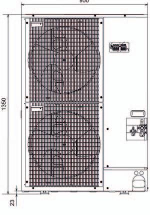
34 REMKO CMF / CMT Unit dimensions Dimensions outdoor module CMF / CMT 120 Dimensions outdoor module CMF / CMT
35 Unit dimensions Dimensions indoor module CMF Series Pipe-socket arrangement Pipe-outlet spacing Refrigerant pipe, 3/8" Refrigerant pipe, 5/8" Hot-water return, 1 AG Hot-water inlet, 1 AG Sockets for safety assembly Condensate-drain socket AD=22 Opening for installing the E-heater controller Fill- and drain valve
36 REMKO CMF / CMT External dimensions, CMT Series indoor module Dimensions indoor module CMT VL-WW RL VL-Hz Refrigerant pipe VL-Hz RL VL-WW Overall dimensions: max Sockets for safety condensate drain Tilt height: 1,900 mm 36
37 Connection diagram, terminal configuration Observe the technical requirements of the local power company ***) Only in a set-up with hot water meters Connection layout CMF/CMT 120/160 **) Only in a set-up without hot water meters On-site sub-distribution Relay switch *) There is an option for the boiler enabling to occur without voltage or with 230 V (phase-bridged from X2.19) with which a normally-closed switch or a normally-open switch can be employed. enable 2. heat source *) (4-way) switching valve 2. heat source 3-way mixer HK2 Flow monitor **) or jumper ***) Circulation pump HK 1 Circulation pump HK 2 Mixer circuit Switching valve Hot-water usage Switching valve, cooling Circulation pump, cooling Circulation pump, solar or circulation or Solid-fuel combustion vessel Charging pump, indoor module F 17 Return, heat pump F 15 Flow rate transmitter F 14 Solar collector Outdoor-module supply CMF/CMT 120: e.g.:nym 3x4mm 2 CMF/CMT 160: e.g.:nym 5x2.5mm 2 Outdoor-module supply e.g.:nym 3x1.5mm 2 E-heater supply e.g.:nym 5x2.5mm 2 Power enable/disable (230 V~) e.g.:nym 3x1.5mm 2 F 13 Solid-fuel combustion vessel br blu F 12 Reference sensor, lower buffer storage F 11 Inlet, heat pump F 9 Outdoor temperature F 8 T-collector (com. inlet) F 6 Warm-water storage F 5 Inlet HK2 (mixing circuit Analogue remote control with room sensor M blk blu br blu blk Normally-closed switch Normally-open switch white L1 N S1 S2 S3 X1.1 X1.2 X1.3 X1.4 X1.5 X1.6 X1.7 X1.8 X1.9 CMF/CMT 120 X2.1 X2.2 X2.3 X2.4 X2.5 X2.6 X2.7 X2.8-N X2.9 X2.10 X2.11-N X2.12 X2.13 X2.14 X2.15 X2.16 X2.17 X2.18 X2.19-L1.1 X2.20-L1.1 X2.21-L1.1 X2.22 X2.23-N X2.24 X2.25 X2.26-N X2.27 X2.28 X2.29-N X2.30 X2.31 X2.32-N X2.33 X2.34 X2.35-N X2.36 X2.37 X2.38-N X2.39 X2.40 X2.41-N X2.42 X3 X3.1 X3.2 X3.3 X3.4 X3.5 X3.6 X3.7 X3.8 X3.9 X3.10 X3.11 X3.12 X3.13 X3.14 X3.15 X3.16 X3.17 X3.18 X3.19 Terminal block X1 Terminal block X2 Terminal block X3 L1 L2 L3 N S1 S2 S3 CMF/CMT 160 Inputs/outputs (Merlin I/O circuit board) A4/A5 E1 A1 A2 A3 A10 A10 A12 A9 F17 (F15) F14 F13 F12 F11 F9 F8 F6 F5 F3 F2 (F1) Outdoor unit Indoor unit 37
38 REMKO CMF / CMT Circuit diagrams Power supply 1~230 V/50Hz Mode switch Hand-OFF-automatic Power plant- Disable/ enable Platine WP-Manager (Merlin I/O circuit board) 6,3 A slow-acting Green indicator light Demand Outdoor unit Circuit diagram WP01 38
39 Circuit diagram (continued) Load pump Indoor unit Special accessories electro heating Platine WP-Manager (Merlin I/O circuit board) Switching valve 2. heat source OPEN CLOSED Circuit diagram WP02 39
40 REMKO CMF / CMT Circuit diagram (continued) Circuit board WP manager (Merlin I/O circuit board) Flow monitor *) or Jumper **) Special accessories electro heating *) only in a set-up without hot water meters **) only in a set-up with hot water meters Circuit diagram WP03 40
41 Circuit diagram (continued) Platine WP-Manager (Merlin I/O circuit board) switching valve Cooling Pump Cooling MF4 outlet for solar pump or circulation pump or solid fuel boiler pump Red indicator light Outdoor-module failure Circuit diagram WP04 41
42 REMKO CMF / CMT Circuit diagram (continued) Power supply for electric booster-heating 400V/3~/50Hz 6 kw switch 3 kw switch Electrical booster heat 3 x 2 kw Circuit diagram WP05 42
43 Circuit diagram (continued) Enable 2 Heat source (potential-free normally open or normally closed switch) Control panel in the indoor module Interface PAC-IF010 B-E Enable compressor Enable Cooling Circuit diagram WP06 43
44 REMKO CMF / CMT Circuit diagram (continued) Pump HK 1 Platine WP-Manager (Merlin I/O circuit board) Pump HK (mixer circuit) 3-way 2 switching valve OPEN Warm- CLOSED water 3-way mixer HK 2 Circuit diagram WP07 44
45 Circuit diagram (continued) Platine WP-Manager (Merlin I/O circuit board) Control panel in the indoor module (Interface PAC-IF010 B-E) Fixed resistor 6.2 kohm Sensor terminal block Undercooling temperature Liquid sensor Circuit diagram WP08 45
46 REMKO CMF / CMT Terminal block/legend X1.2 Power supply, indoor module - N X1.3 Power supply, indoor module - PE X1.4 X1.5 X1.6 X1.7 X1.8 X1.9 PE X2.2 Control cable, outdoor- and indoor module - S2 X2.3 Control cable, outdoor- and indoor module - S3 X2.4 Enable 2. Heat generator (common contact, optionally potential free or 230 V feed over the bridge at X2.19) X2.5 Enable 2. Heat source (open) X2.6 Enable 2. Heat source (closed) X.2.7 Switching valve 2. Heat generator - OPEN X2.8 Switching valve 2. Heat generator - N X2.9 Switching valve 2. Heat generator - OFF X2.10 Mixer, heating circuit 2 - OPEN X211 Mixer, heating circuit 2 - N X2.12 Mixer, heating circuit 2 - CLOSED X2.13 Power plant enable/disable X2.14 Power plant enable/disable X2.15 Contactor K6-A1/L, 6 kw elec. booster heater X2.16 Flow monitor X2.17 Flow monitor X2.18 Contactor K6 and K8-A2/N1.2, elec. booster heater X2.19 Live phase - L' X2.20 Live phase - L' X2.21 Live phase - L' X2.22 Circulation pump, heating circuit 1 - L X2.23 Circulation pump, heating circuit 1 - N X2.24 Circulation pump, heating circuit 1 - PE X2.25 Circulation pump, heating circuit 2 - L X2.26 Circulation pump, heating circuit 2 - N X2.27 Circulation pump, heating circuit 2 - PE X2.28 Switching valve, warm water L" - black X2.29 Switching valve, warm water N - grey X2.30 PE Power supply, E-heater - L1 (optional for CMF Series). Power supply, E-heater - N (optional for CMF Series). Power supply, E-heater - PE (optional for CMF Series). Power supply, E-heater - L2 (optional for CMF Series). Power supply, E-heater - L3 (optional for CMF Series). Terminal Connection layout (low-voltage sensor) X3. Earth Terminal Connection layout (outputs) X2.1 Control cable, outdoor- and indoor module - S1 Terminal Connection layout (supply) X1.1 Power supply, indoor module - L Terminal Connection layout (outputs) continuation X2.31 Switching valve, cooling L" - black X2.32 Switching valve, cooling N - grey X2.33 PE X2.34 Circulation pump, cooling - L X2.35 Circulation pump, cooling - N X2.36 Circulation pump - PE X2.37 Circulation- or solar pump - L X2.38 Circulation- or solar pump - N X2.39 Circulation- or solar pump - PE X2.40 Charge pump, indoor module - L X2.41 Charge pump, indoor module - N X2.42 Charge pump, indoor module - PE X3.1 CAN-Bus + X3.2 CAN-Bus - X3.3 CAN-Bus L X3.4 CAN-Bus H X3.5 ebus - (nominal output in % above 0-10 V -signal) X3.6 ebus + (nominal output in % above 0-10 V -signal) X3.7 F17 Return sensor (cooling-control sensor) X3.8 F15 sensor (option: flow-volume regulator) X3.9 F14 Solar-collector or Solid-fuel-boiler sensor (pt 1000) X3.10 (not connected) X3.11 F12 Lower buffer storage (reference sensor, solar or solid-fuel boiler) X3.12 F11 Inlet sensor, heat pump or heating-circuit 1 X3.13 F9 External sensor X3.14 F8 Collector sensor, common inlet (heating-control sensor) X3.15 F6 Warm-water-storage sensor X3.16 F5 Inlet sensor, heating-circuit 2 (mixing circuit) X3.17 F3 (not connected) X3.18 F2 (not connected) X3.19 F1 (not connected) X3.20 Liquid-temperature sensor, cooling circuit X3.21 Undercooling temperature, cooling circuit NOTE The connection terminals X1.4 through x1.9, as well as X2.15 and X2.18 are available only when the electric booster heater is installed or when it is standard equipment (CMT) 46
47 Characteristic curves Heat output CMF / CMT Heat output at an inlet temperature of 35 C 14 n-max 12 Rated frequency 96/99 Hz Heating output [kw] n-min Outdoor temperature [ C] Performance number CMF / CMT COP at an inlet temperature of 35 C 5 4 COP [-] Outdoor temperature [ C] Diagramm COP W35_8 kw 47
48 REMKO CMF / CMT Characteristic curves Heat output CMF / CMT Heat output at an inlet temperature of 45 C 12 n-max Heating output [kw] Rated frequency 96/99 Hz n-min Outdoor temperature [ C] Diagramm Heizleistung W45_8 kw Performance number CMF / CMT COP at an inlet temperature of 45 C 5 4 COP [-] Outdoor temperature [ C] 48
49 Characteristic curves Heat output CMF / CMT Heat output at an inlet temperature of 55 C 12 n-max 10 Rated frequency 96/99 Hz Heating output [kw] n-min Outdoor temperature [ C] Diagramm Heizleistung W55_8 kw Performance number CMF / CMT COP at an inlet temperature of 55 C 3 COP [-] Outdoor temperature [ C] 49
50 REMKO CMF / CMT Characteristic curves Heat output CMF / CMT Heat output at an inlet temperature of 35 C 25 n-max Heating output [kw] Rated frequency 76/77 Hz n-min Outdoor temperature [ C] Diagramm Heizleistung W35_14kW Performance number CMF / CMT COP at an inlet temperature of 35 C 6 5 COP [-] Outdoor temperature [ C] 50
51 Characteristic curves Heat output CMF / CMT 160 Heat output at an inlet temperature of 45 C 25 n-max 20 Rated frequency 76/77 Hz Heating output [kw] n-min Outdoor temperature [ C] Diagramm Heizleistung W45_14kW Performance number CMF / CMT COP at an inlet temperature of 45 C 4 3 COP [-] Outdoor temperature [ C] 51
52 REMKO CMF / CMT Characteristic curves Heat output CMF / CMT 160 Heat output at an inlet temperature of 55 C n-max 14 Heating output [kw] Rated frequency 76/77 Hz n-min Outdoor temperature [ C] Diagramm Heizleistung W55_14kW Performance number CMF / CMT COP at an inlet temperature of 55 C 3 COP [-] Outdoor temperature [ C] 52

 In free field In front of a wall 53,1 db(a) 39,1 db(a) 33,1 db(a) 29,6 db(a) 56,1 db(a) 42,1 db(a) 36,1 db(a) 32,6 db(a) CMF/CMT 160")
53 Pump-characteristic curves, indoor module charging pump Pump characteristic curves for models CMF / CMT 120 Pump characteristic curves for models CMF / CMT 160 Level Output in W Current in A I 25 0,12 II 35 0,16 III 45 0,20 Level Output in W Current in A I 50 0,22 II 55 0,27 III 60 0,30 Sound pressure level Distance-dependent sound pressure level for the outdoor unit in relation to installation type, in accordance with the drawing 1m 1m 5m 10m 1m 5m 10m Distance-dependent sound pressure level Heat pump outdoor unit Sound power level according to ISO Installation type, in accordance with the drawing 1m 5m 10m 15m CMF/CMT ,1 db(a) In free field In front of a wall 53,1 db(a) 39,1 db(a) 33,1 db(a) 29,6 db(a) 56,1 db(a) 42,1 db(a) 36,1 db(a) 32,6 db(a) CMF/CMT ,1 db(a) In free field In front of a wall 56,1 db(a) 42,1 db(a) 36,1 db(a) 32,6 db(a) 59,1 db(a) 45,1 db(a) 39,1 db(a) 35,6 db(a) 53
54 REMKO CMF / CMT Overall sound pressure levels for outdoor module CMF/CMT 120 Total sound-power level L P Excluded range db A L Output A-bew Cursor: (A)Power=64.1 db Hz Middle frequency (Hz) 25 31, LI [dba] (35,1) (38,0) (38,7) 39,8 40,2 39,6 49,9 37,2 35,6 LWo [dba] (43,1) (45,9) (46,6) 47,7 48,1 47,5 57,8 45,1 43,5 FPI [db] -(17,2) -(10,1) -(5,6) -14,2-11,4-1,6 4,8 3,6 6,4 Middle frequency (Hz) LI [dba] 44,5 41,2 42,5 42,9 43,1 44,3 44,4 45,5 43,2 LWo [dba] 52,4 49,1 50,4 50,8 51,0 52,2 52,3 53,5 51,1 FPI [db] 5,9 4,7 4,5 5,4 4,8 4,0 3,7 4,1 4,4 Middle frequency (Hz) LI [dba] 45,0 43,2 37,5 36,7 34,4 31,2 28,2 (24,1) (22,8) LWo [dba] 52,9 51,1 45,4 44,7 42,3 39,1 36,1 (32,0) (30,7) FPI [db] 4,6 4,4 3,7 3,7 4,4 4,2 4,0 (3,8) (3,3) Determination of sound power conforms to accuracy class 2, the standard deviation of the o. a. A-valued sound-power levels amounts to 1.5 db. LWo: Sound power level radiated by the outdoor unit FPI: Correction value with regard to the environment LI: Sound intensity 54
 25 31,50 40 50 63 80 100 125 160 LI [dba] (31,8) -(35,6) (34,6) 40,5 41,5 42,2 40,0 37,6 39,4 LWo [dba] (41,0) -(44,8) (43,8) 49,7 50,7 51,4 49,2 46,8 48,6 FPI [db] -(7,9)")
![-(1,4) -(5,5) -9,2-3,9 0,6 3,3 6,0 6,7 Middle frequency (Hz) 200 250 315 400 500 630 800 1000 1250 LI [dba] 41,8 50,8 42,6 46,6 47,1 47,9 47,7 46,5 46,1 LWo [dba] 51,0 60,0 51,8 55,8 56,3 57,1 56,9](/docs-images/87/96376478/images/55-1.jpg "55,7 55,3 FPI [db] 8,7 7,7 9,3 7,6 7,6 6,5 6,3 7,2 7,5 Middle frequency (Hz) 1600 2000 2500 3150 4000 5000 6300 8000 10000 LI [dba] 45,9 45,4 40,9 37,1 32,4 33,3 25,1 (24,9) (19,9) LWo [dba] 55,1")
55 Overall sound pressure levels for outdoor module CMF/CMT 160 Total sound-power level L P Excluded range Ambient noise Output A-bew Cursor: (A)Power=67.1 db Middle frequency (Hz) 25 31, LI [dba] (31,8) -(35,6) (34,6) 40,5 41,5 42,2 40,0 37,6 39,4 LWo [dba] (41,0) -(44,8) (43,8) 49,7 50,7 51,4 49,2 46,8 48,6 FPI [db] -(7,9) -(1,4) -(5,5) -9,2-3,9 0,6 3,3 6,0 6,7 Middle frequency (Hz) LI [dba] 41,8 50,8 42,6 46,6 47,1 47,9 47,7 46,5 46,1 LWo [dba] 51,0 60,0 51,8 55,8 56,3 57,1 56,9 55,7 55,3 FPI [db] 8,7 7,7 9,3 7,6 7,6 6,5 6,3 7,2 7,5 Middle frequency (Hz) LI [dba] 45,9 45,4 40,9 37,1 32,4 33,3 25,1 (24,9) (19,9) LWo [dba] 55,1 54,6 50,1 46,3 41,6 42,5 34,3 (34,1) (29,1) FPI [db] 7,3 7,1 6,6 8,4 10,3 7,3 11,9 (7,2) (6,4) Determination of sound power conforms to accuracy class 2, the standard deviation of the o. a. A-valued sound-power levels amounts to 1.5 db. LWo: Sound power level radiated by the outdoor unit FPI: Correction value with regard to the environment LI: Sound intensity 55
56 REMKO CMF / CMT Annual performance number for CMF/CMT 120 / CMF/CMT 160 Mode: single energy source, parallel with a switch-over point of -5 C Climatic region: -10 C Existing buildings with hot-water heating (share 18%) Annual performance number with inlet/outlet temperature differential: 7K and inlet temperature... perature differential: 10K and inlet temperature... Annual performance number with inlet/outlet tem- COP Type A-7/W35 A2/W35 A10/W35 30 C 35 C 40 C 45 C 50 C 55 C CMF/CMT 120 2,5 3,9 4,4 4,15 4,03 3,82 3,87 3,74 3,60 CMF/CMT 160 2,6 3,9 4,7 4,22 4,09 3,97 3,93 3,80 3,66 New construction with hot-water heating (share 18%) Annual performance number with inlet/outlet temperature differential: 7K and inlet temperature... perature differential: 10K and inlet temperature... Annual performance number with inlet/outlet tem- COP Type A-7/W35 A2/W35 A10/W35 30 C 35 C 40 C 45 C 50 C 55 C CMF/CMT 120 2,5 3,9 4,4 4,07 3,95 3,91 3,78 3,64 3,50 CMF/CMT 160 2,6 3,9 4,7 4,11 3,99 3,86 3,89 3,68 3,54 Climatic region: -12 C Existing buildings with hot-water heating (share 18%) Annual performance number with inlet/outlet temperature differential: 7K and inlet temperature... perature differential: 10K and inlet temperature... Annual performance number with inlet/outlet tem- COP Type A-7/W35 A2/W35 A10/W35 30 C 35 C 40 C 45 C 50 C 55 C CMF/CMT 120 2,5 3,9 4,4 4,07 3,95 3,82 3,79 3,68 3,53 CMF/CMT 160 2,6 3,9 4,7 4,12 4,00 3,88 3,84 3,71 3,58 New construction with hot-water heating (share 18%) Annual performance number with inlet/outlet temperature differential: 7K and inlet temperature... perature differential: 10K and inlet temperature... Annual performance number with inlet/outlet tem- COP Type A-7/W35 A2/W35 A10/W35 30 C 35 C 40 C 45 C 50 C 55 C CMF/CMT 120 2,5 3,9 4,4 3,98 3,86 3,73 3,69 3,56 3,43 CMF/CMT 160 2,6 3,9 4,7 4,06 3,89 3,81 3,73 3,60 3,46 Climatic region: -14 C Existing buildings with hot-water heating (share 18%) Annual performance number with inlet/outlet temperature differential: 7K and inlet temperature... perature differential: 10K and inlet temperature... Annual performance number with inlet/outlet tem- COP Type A-7/W35 A2/W35 A10/W35 30 C 35 C 40 C 45 C 50 C 55 C CMF/CMT 120 2,5 3,9 4,4 4,00 3,89 3,77 3,74 3,61 3,49 CMF/CMT 160 2,6 3,9 4,7 4,10 3,98 3,87 3,79 3,67 3,54 New construction with hot-water heating (share 18%) Annual performance number with inlet/outlet temperature differential: 7K and inlet temperature... perature differential: 10K and inlet temperature... Annual performance number with inlet/outlet tem- COP Type A-7/W35 A2/W35 A10/W35 30 C 35 C 40 C 45 C 50 C 55 C CMF/CMT 120 2,5 3,9 4,4 3,92 3,80 3,68 3,64 3,52 3,39 CMF/CMT 160 2,6 3,9 4,7 4,00 3,88 3,75 3,68 3,55 3,42 Climatic region: -16 C Existing buildings with hot-water heating (share 18%) Annual performance number with inlet/outlet temperature differential: 7K and inlet temperature... perature differential: 10K and inlet temperature... Annual performance number with inlet/outlet tem- COP Type A-7/W35 A2/W35 A10/W35 30 C 35 C 40 C 45 C 50 C 55 C CMF/CMT 120 2,5 3,9 4,4 3,89 3,78 3,67 3,64 3,52 3,39 CMF/CMT 160 2,6 3,9 4,7 3,95 3,84 3,72 3,69 3,57 3,45 New construction with hot-water heating (share 18%) Annual performance number with inlet/outlet temperature differential: 7K and inlet temperature... perature differential: 10K and inlet temperature... Annual performance number with inlet/outlet tem- COP Type A-7/W35 A2/W35 A10/W35 30 C 35 C 40 C 45 C 50 C 55 C CMF/CMT 120 2,5 3,9 4,4 3,79 3,67 3,56 3,52 3,41 3,28 CMF/CMT 160 2,6 3,9 4,7 3,83 3,72 3,60 3,56 3,45 3,32 Note: A differential of 7K has a standard floor-heating layout, a differential of 10K is typical for a radiator system Additional key data: a heating-threshold temperature of 15 C for old construction and 12 C in new construction, a differential at the condenser (test-bench measurements: 5K) 56
57 Annual performance number for CMF/CMT 120 / CMF/CMT 160 Mode: bivalent-parallel with a switch-over point of -3 C Climatic region: -10 C Existing buildings with hot-water heating (share 18%) Annual performance number with inlet/outlet temperature differential: 7K and inlet temperature... perature differential: 10K and inlet temperature... Annual performance number with inlet/outlet tem- COP Type A-7/W35 A2/W35 A10/W35 30 C 35 C 40 C 45 C 50 C 55 C CMF/CMT 120 2,5 3,9 4,4 4,44 4,30 4,16 4,11 3,96 3,80 CMF/CMT 160 2,6 3,9 4,7 4,52 4,37 4,23 4,18 4,03 3,87 New construction with hot-water heating (share 18%) Annual performance number with inlet/outlet temperature differential: 7K and inlet temperature... perature differential: 10K and inlet temperature... Annual performance number with inlet/outlet tem- COP Type A-7/W35 A2/W35 A10/W35 30 C 35 C 40 C 45 C 50 C 55 C CMF/CMT 120 2,5 3,9 4,4 4,34 4,20 4,05 4,00 3,85 3,69 CMF/CMT 160 2,6 3,9 4,7 4,40 4,25 4,10 4,05 3,90 3,74 Climatic region: -12 C Existing buildings with hot-water heating (share 18%) Annual performance number with inlet/outlet temperature differential: 7K and inlet temperature... perature differential: 10K and inlet temperature... Annual performance number with inlet/outlet tem- COP Type A-7/W35 A2/W35 A10/W35 30 C 35 C 40 C 45 C 50 C 55 C CMF/CMT 120 2,5 3,9 4,4 4,34 4,20 4,06 4,01 3,87 3,72 CMF/CMT 160 2,6 3,9 4,7 4,41 4,27 4,13 4,08 3,94 3,79 New construction with hot-water heating (share 18%) Annual performance number with inlet/outlet temperature differential: 7K and inlet temperature... perature differential: 10K and inlet temperature... Annual performance number with inlet/outlet tem- COP Type A-7/W35 A2/W35 A10/W35 30 C 35 C 40 C 45 C 50 C 55 C CMF/CMT 120 2,5 3,9 4,4 4,24 4,10 3,95 3,91 3,76 3,61 CMF/CMT 160 2,6 3,9 4,7 4,29 4,15 4,00 3,95 3,81 3,65 Climatic region: -14 C Existing buildings with hot-water heating (share 18%) Annual performance number with inlet/outlet temperature differential: 7K and inlet temperature... perature differential: 10K and inlet temperature... Annual performance number with inlet/outlet tem- COP Type A-7/W35 A2/W35 A10/W35 30 C 35 C 40 C 45 C 50 C 55 C CMF/CMT 120 2,5 3,9 4,4 4,27 4,13 4,00 3,96 3,72 3,68 CMF/CMT 160 2,6 3,9 4,7 4,34 4,20 4,07 4,03 3,88 3,74 New construction with hot-water heating (share 18%) Annual performance number with inlet/outlet temperature differential: 7K and inlet temperature... perature differential: 10K and inlet temperature... Annual performance number with inlet/outlet tem- COP Type A-7/W35 A2/W35 A10/W35 30 C 35 C 40 C 45 C 50 C 55 C CMF/CMT 120 2,5 3,9 4,4 4,17 4,03 3,89 3,85 3,71 3,56 CMF/CMT 160 2,6 3,9 4,7 4,22 4,08 3,94 3,90 3,75 3,61 Climatic region: -16 C Existing buildings with hot-water heating (share 18%) Annual performance number with inlet/outlet temperature differential: 7K and inlet temperature... perature differential: 10K and inlet temperature... Annual performance number with inlet/outlet tem- COP Type A-7/W35 A2/W35 A10/W35 30 C 35 C 40 C 45 C 50 C 55 C CMF/CMT 120 2,5 3,9 4,4 4,14 4,01 3,88 3,84 3,71 3,57 CMF/CMT 160 2,6 3,9 4,7 4,22 4,08 3,95 3,92 3,78 3,64 New construction with hot-water heating (share 18%) Annual performance number with inlet/outlet temperature differential: 7K and inlet temperature... perature differential: 10K and inlet temperature... Annual performance number with inlet/outlet tem- COP Type A-7/W35 A2/W35 A10/W35 30 C 35 C 40 C 45 C 50 C 55 C CMF/CMT 120 2,5 3,9 4,4 4,02 3,89 3,76 3,72 3,58 3,44 CMF/CMT 160 2,6 3,9 4,7 4,08 3,95 3,82 3,77 3,64 3,49 Note: A differential of 7K has a standard floor-heating layout, a differential of 10K is typical for a radiator system Additional key data: a heating-threshold temperature of 15 C for old construction and 12 C in new construction, a differential at the condenser (test-bench measurements: 5K) 57
58 REMKO CMF / CMT Technical data Series CMF 120 CMT 120 CMF 160 CMT 160 Function Inverter technology System Heat pump manager Heating or Cooling REMKO SuperTec Split-Air/Water Multitalent Storage tank for hydraulic decoupling of volumetric flows on site 150 l on site 150 l Electric booster heating / rated output kw optional Series / 6 optional Series / 6 Water heating optional with separate storage technology Heating output min / max kw 3,5-11,0 5,0-16,0 Heating output / compressor frequency / COP 1) for A10/W35 kw / Hz / - 10,5 / 99 /4,4 15,3 / 76 / 4,7 Heating output / compressor frequency / COP 1) for A7/W35 kw / Hz / - 10,0 / 96 /4,3 13,0 / 77 / 4,4 Heating output / compressor frequency / COP 1) for A2/W35 kw / Hz / - 7,2 / 96 /3,4 9,6 / 76 / 3,2 Heating output / compressor frequency / COP 1) for A2/W35 kw / Hz / - 5,1 / 61 / 3,9 8,0 / 51 / 3,9 Heating output / compressor frequency / COP 1) for A7/W35 kw / Hz / - 4,8 / 99 /2,5 8,2 / 77 / 2,6 Heating output / compressor frequency / COP 1) for A15/W35 kw / Hz / - 3,8 / 99 / 1,9 5,43 / 77 / 1,7 Heating output / compressor frequency / COP 1) for A7/W45 kw / Hz / - 9,4 / 99 / 3,4 13,3 / 76 / 3,4 Heating output / compressor frequency / COP 1) for A2/W45 kw / Hz / - 7,0/ 96 / 2,8 9,3 / 76 / 2,5 Heating output / compressor frequency / COP 1) for A7/W45 kw / Hz / - 5,2 / 99 / 2,2 7,4 / 77 / 1,9 Heating output / compressor frequency / COP 1) for A15/W45 kw / Hz / - 4,3 / 116 / 1,5 4,6 / 77 / 1,2 Heating output / compressor frequency / COP 1) for A20/W55 kw / Hz / - 10,4 / 94 / 3,0 12,9 / 61 / 3,4 Heating output / compressor frequency / COP 1) for A7/W55 kw / Hz / - 7,9 / 89 / 2,5 9,4 / 61 / 2,5 Heating output / compressor frequency / COP 1) for A7/W55 kw / Hz / - 3,1 / 95 / 1,1 6,1 / 77 / 1,3 Cooling output / compressor frequency / EER 2) for A35/W7 kw / Hz / - 5,4 / 70 / 2,9 12,1 / 74 / 3,1 Cooling output / compressor frequency / EER 2) for A27/W7 kw / Hz / - 5,9 / 70 / 3,5 12,0 / 69 / 3,7 Service limits, heating C -18 to +34 Service limits, cooling C +15 to +46 Supply-temperature, heating water C up to +60 Refrigerant / pre-charge quantity -- / kg R 410A 2) / 3.5 R 410A 2) / 5.0 Refrigerant / pre-charge quantity for up to 30 m length of ordinary pipe g/m 60 Max. permissible single refrigerant pipe length m Power supply V / Hz 230/1~ / /3~N / 50 Starting current A 12,5 8 Rated current consumption (for A7/W35) A 13 5,3 Rated power consumption (for A7/W35) kw 2,32 2,95 Fuse protection (outdoor unit), characteristic C A 25 3 x 16 Rated water flow (according to EN 14511, at t 5 K) m³/h 1,7 2,2 Pressure-loss at the condenser at rated flow kpa 5,4 8,1 Airflow volume outdoor module m³/h Max. operating pressure, water bar 3,0 Hydraulic connection, supply / return Inches 1 AG 1 AG 1 AG 1 AG Sound-pressure level, LpA 1m (outdoor unit) db(a) 53/39 3) 56/42 3) Sound-power level in accordance with DIN EN 12102: and ISO db(a) 64,1 67,1 Dimensions, indoor unit (height/width/depth) mm 800/550 / /550/ /550/ /550/670 Dimensions, outdoor unit (height/width/depth) mm 945/950/ / 1050 / 330 Protection class outdoor unit IP 24 IP 24 Weight indoor module kg Weight outdoor module kg ) COP=coefficient of performance or performance number according to EN ) Contains greenhouse gas according to Kyoto protocol 3) Clear-field distance: 5m 58
59 Exploded view outdoor module CMF 120, CMT We reserve the right to modify the dimensions and constructional design as part of the ongoing technical-development process. Spare parts list No. Designation CMF 120 CMT 120 EDP -number EDP -number 1 Compressor Laminated heat-exchanger Four-way switching valve Shut-off valves Fan Cover panel Side panel, left Front panel Grille Side panel, right rear Side panel, right front Cover, rear Cover, front Recessed grip Grid Spare parts (not illustrated) Sensor available only by request with the device no. Control board available only by request with the device no. Mains filter board available only by request with the device no. Power electronics available only by request with the device no. When ordering spare parts, please state the computerised part no., device number and device type (see name plate)! 59

60 REMKO CMF / CMT Exploded view outdoor module CMF 160, CMT We reserve the right to modify the dimensions and constructional design as part of the ongoing technical-development process. Spare parts list 60 No. Designation CMF 160 CMT 160 EDP -number EDP -number 1 Compressor Laminated heat-exchanger Four-way switching valve Shut-off valves Fan Cover panel Side panel, left Front panel Grille, front Side panel, right Side panel, right front Cover, rear Cover, front Recessed grip Spare parts (not illustrated) Grille, rear Sensor available only by request with the device no. Control board available only by request with the device no. Mains filter board available only by request with the device no. Power electronics available only by request with the device no. When ordering spare parts, please state the computerised part no., device number and device type (see name plate)!

61 Device display for indoor module CMF 120, CMF We reserve the right to modify the dimensions and constructional design as part of the ongoing technical-development process. 61
62 REMKO CMF / CMT Spare parts list No. Designation CMF 120 CMF Housing Front panel Door with hinge Housing for controls Controls, complete Control module Control module (in the form of a hot water meter) Heat exchanger (condenser) with insulation Pipe assembly, complete with insulation Circulation pump Flow monitor Flow meter (in the form of a hot water meter) Fill/drain valve Bleeder 1 / Brass plug, 2" Relay board, WP-Manager (Merlin I/O-Platine) Relay board, WP-Manager (in the form of a hot water meter) Control board (Interface PAC-IF010B-E) Mount Sensor terminal block Red indicator light Green indicator light Mode switch Relays (finder) Retrofitting kit electric heating Spare parts (not illustrated) Liquid sensor, cooling circuit Socket for service module Blind plug Electric booster-heating, 2", max. 9 kw Parts and fittings, set No. Designation CMF 120 CMF Fittings set, complete Dirt trap Ball valve, 1" red Ball valve, 1" blue Contact sensor Immersion sensor Safety assembly External sensor When ordering spare parts, please state the computerised part no., device number and device type (see identification plate)! 62

63 Device display for indoor module CMT 120, CMT We reserve the right to modify the dimensions and constructional design as part of the ongoing technical-development process. 63
64 REMKO CMF / CMT Spare parts list No. Designation CMT 120 CMT Housing 2 Front panel, upper Front panel, centre Front panel, lower Base-feet, set Buffer storage with insulation 7 Fill/drain valve Housing for controls Controls, complete Control module Control module (in the form of a hot water meter) Circulation pump Heat exchanger with insulation Pipe assembly, complete with insulation Immersion sensor way switching valve, hydraulic, lower part Flow monitor Flow meter (in the form of a hot water meter) Electric booster-heating, 2", max. 9 kw Bleeder 1 / Relay board, WP-Manager (Merlin I/O-Platine) Relay board, WP-Manager (in the form of a hot water meter) Control board (Interface PAC-IF010B-E) Mount Sensor terminal block Red indicator light Green indicator light Mode switch Relays (finder) Retrofitting kit electric heating Spare parts (not illustrated) Actuator for 3-way switching valve Valve-core for 3-way switching valve Liquid sensor, cooling circuit Socket for service module Blind plug Parts and fittings, set 64 Designation CMT 120 IT CMT 160 IT 14 Immersion sensor Fittings set, complete (see below) Dirt trap Ball valve, 1" red Ball valve, 1" blue Contact sensor Safety assembly External sensor When ordering spare parts, please state the computerised part no., device number and device type (see identification plate)!
65 EC Declaration of Conformity We do hereby declare that the devices named below, produced and sold by us, satisfy the relevant basic requirements of the EC guidelines, the EC safety standards and other product-specific EC standards. Important Information: In the event that the equipment delivered to the work site is not used, installed or maintained as intended, or is modified without authorization, this declaration loses its legal validity. Name of Manufacturer: Equipment (machinery) - Implementation: REMKO GmbH & Co. KG Air conditioning and heating technology Im Seelenkamp 12 D Lage Inverter heat pump with refrigerant R410A Series / Designation: CMF 120, CMF 160, CMT 120, CMT 160 Series / Class Number: and Applicable regulations : 2006/42/EC Machine directive (EC-Directive) 2006/95/EC Low-voltage directive 2004/108/EC Electro-magnetic fields 97/23/EC Pressure Equipment Directive Applicable Standards: EN 378-1: 2008 Cooling-devices and heat-pump safety- (Harmonized EN) and environment-related requirements EN 378-2: 2008 EN 378-3: 2008 EN 378-4: 2008 EN 50366: 2003 Electrical devices for household use and similar purposes - electromagnetic fields EN : Electromagnetic compatibility - requirements for household appliances, electric tools and similar electrical devices (earlier: VDE 0875) EN : 1997 / Safety of electrical devices for house- A1: 2001 (Category IV) hold use and similar purposes (earlier: VDE 0700) EN : 2002 / A11: 2004 / A1: 2004 EN : 2003 / A11: 2004 / A12: 2005 / A1: 2006 EN : 2006 EN : 1995 / A1: 2001 / A2: 2005 Electromagnetic compatibility (EMV, earlier: VDE 0838) REMKO GmbH & Co. KG Lage, 25. February Signature Product Manager 65
66 REMKO CMF / CMT General terms Defrost At outdoor temperatures below 5 C it is possible that ice may form on the evaporators of air/water heat pumps. The removal of this ice is referred to as defrosting and is undertaken by supplying heat, either regularly or as requirements dictate. Air/water heat pumps with circuit reversal are distinguished by their requirements-based, quick and energy-efficient defrosting system. Bivalent mode The heat pump provides the entire heating energy down to a predetermined outdoor temperature (e.g. 0 C). If the temperature drops below this value, the heat pump switches off and the secondary heating appliance takes over the heating, e.g. a heating boiler. Seal inspection System operators are obliged to ensure the prevention of refrigerant leakage in accordance with the directive on substances that deplete the ozone layer (EC 2037/2000) and the Regulation on Certain Fluorinated Greenhouse Gases (EC 842/2006). In addition, a minimum of one annual service and inspection must be carried out, as well as a sealing test for refrigerating plants with a refrigerant filling weight over 3 kg. Energy supply company switching Certain energy supply companies offer special tariffs for the operation of heat pumps. Expansion valve Heat pump component for lowering the condensing pressure on the vapour tension. In addition, the expansion valve regulates the quantity of injected refrigerant in relation to the evaporator load. Support The German Reconstruction Loan Corporation supports ecologically-sound construction and modernisation of domestic buildings for private individuals. This includes heat pumps which can be supported in the form of loans. The German Federal Office of Economics and Export Control (BAFA) subsidises the installation of effective heat pumps (please refer to: und Limit temperature / bivalence point Outdoor temperature where the secondary heating appliance cuts in under bivalent operation. Heating output Flow of heat emitted from the liquefier to the environment. The heating output is the sum of the electrical power consumed by the condenser and the heat flux obtained from the environment. Inverter power regulator which serves to match the speed of the compressor motor and the speed of the evaporator fans to the heating requirement. Seasonal performance factor The seasonal performance factor relates to the ratio of heat content delivered by the heat pump system to the supplied electrical energy in one year. It may not be compared to the performance number. The seasonal performance factor expresses the reciprocal of the annual power input factor Annual power input factor The annual power input factor indicates the power input (e.g. electrical energy) required in order to achieve a certain benefit (e.g. heating energy). The annual power input factor includes the energy required for auxiliary drives. Calculation of the annual power input factor is undertaken according to VDI Directive Refrigerating capacity Heat flux extracted from the environment by the evaporator (air, water or soil). Refrigerant The working medium used in a refrigerant plant, e.g. heat pump, is referred to as the refrigerant. The refrigerant is a liquid which is used for thermal transfer in a refrigeration plant and which is able to absorb heat by changing its state at low temperatures and low pressures. A further change of state at higher temperatures and higher pressure serves to dissipate this heat. Compressor (condenser) Unit designed for the mechanical conveyance and compression of gasses. Compression serves to significantly increase the pressure and temperature of the medium. 66
67 Coefficient of performance The current ratio of thermal output produced by the heat pump to the consumed electrical power is referred to as the coefficient of performance, as measured under standardised boundary conditions according to EN 255 / EN A coefficient of performance of 4 means that a usable thermal output amounting to 4-times the electrical power consumption is available. Single energy-source mode The heat pump covers a large proportion of the required thermal output. On a few days per year an electrical heating coil supplements the heat pump under extremely low outdoor temperatures. Dimensioning of the heat pump for air/water heat pumps is generally based on a limit temperature (also known as balance point) of approx. -5 C. Monovalent mode In this mode, the heat pump is the sole heating appliance in the building all year round. Monovalent mode is primarily used in combination with brine/water and water/water heat pumps. Storage tank The installation of a hotwater storage tank is generally recommended in order to extend the running time of the heat pump under low heat requirements. A storage tank is required for air/ water heat pumps in order to bridge off-periods. Noise Noise is transmitted in media such as air or water. Essentially there are two types of noise, airborne sound and solid-borne sound. Airborne sound is transmitted entirely via the air. Solid-borne sound is transmitted in solid materials or liquids and is only partially radiated as airborne sound. The audible range of sound lies between 20 and 20,000 Hz. Sound pressure level The sound pressure level is a comparable characteristic quantity for the radiated acoustic output of a machine, for example, a heat pump. The noise emission level at certain distances and acoustic environments can be measured. The standard is based on a sound pressure level given as a nominal noise level. Split AC unit Design where one part of the device is positioned outdoors and the other inside the building. Both units are connected to each other by a refrigerant pipe. Evaporator Heat exchanger on a refrigerant plant which uses the evaporation of a working medium in order to extract heat from its environment at low temperatures (e.g. the outdoor air). Condenser Heat exchanger on a refrigerant plant which liquefies a working medium in order to transmit heat to its environment (e.g. the heating system). Regulations and guidelines The erection, installation and commissioning of heat pumps has to be undertaken by qualified specialist engineers. In doing so, various standards and directives are to be observed. Heat requirement assessment A precise dimensioning of the system must be carried out for heat pump systems in order to maximise efficiency. Calculation of the heat requirement is undertaken according to national standards. However, approximate requirements can be determined based on the W/m² tables multiplied by living space to be heated. The result of this is the overall heat requirement, which includes the transmission heat requirement and the infiltration heat loss. Heat pump system A heat pump system consists of a heat pump and a heat source system. For brine and water/water heat pumps, the heat source system must be made available separately. Heat source Medium from which the heat pump derives heat, in other words, soil, air and water. Heat carrier Liquid or gas medium (e.g. water, brine or air), in which heat is transported. 67


68 REMKO INTERNATIONAL and also right in your neighbourhood! Make use of our experience and advice Consulting Thanks to intensive training, our consultants are always completely up-to-date in terms of technical knowledge. This has given us the reputation of being more than just an excellent, reliable supplier: REMKO, a partner helping you find solutions to your problems. REMKO GmbH & Co. KG Air conditioning and heating technology Im Seelenkamp 12 D Lage Postfach 1827 D Lage Telephone Telefax info@remko.de Website Distribution REMKO offers not just a well established sales network both nationally and internationally, but also has exceptionally highlyqualified sales specialists. REMKO field staff are more than just sales representatives: above all, they must act as advisers to our customers in air conditioning and heating technology. SFlbCustomer Service Our equipment operates precisely and reliably. However, in the event of a fault, REMKO customer service is quickly at the scene. Our comprehensive network of experienced dealers always guarantees quick and reliable service. We reserve the right to make technical changes, and provide no guarantee as to the accuracy of this data!
Installation and operating instructions. DK energy storage and DK energy buffer
 Installation and operating instructions DK energy storage and DK energy buffer Edition: 08-2015 1 Preliminary note With this DK energy storage / DK energy buffer you purchased a DK quality product. The
Installer manual AG-AA10. Air/air heat pump IHB GB AG-AA10-30 AG-AA10-40/50
 -30 Installer manual Air/air heat pump -40/50 IHB GB 1516-1 331554 Table of Contents 1 Important information 2 5 Installation 7 Safety information 2 Model combinations 7 Read before starting the installation
DLCLRA. INSTALLATION INSTRUCTIONS Outdoor Unit Single Zone Ductless System Sizes 36 to 58 TABLE OF CONTENTS
 DLCLRA INSTALLATION INSTRUCTIONS Outdoor Unit Single Zone Ductless System Sizes 36 to 58 Fig. 1 - Size 36 TABLE OF CONTENTS PAGE SAFETY CONSIDERATIONS... 2 PARTS LIST... 3 SYSTEM REQUIREMENTS... 4 WIRING...
Installation Instructions
 38MHR Outdoor Unit Single Zone Ductless System Sizes 09 to 24 Installation Instructions NOTE: Read the entire instruction manual before starting the installation. NOTE: Images are for illustration purposes
Servicing manual. Wall-mounted condensing gas boiler 600 Series - 11S / 19S / 24S / 24C /2002 GB(EN) For trade use
 For trade use") GB122 7210 1300-12/2002 GB(EN) For trade use Servicing manual Wall-mounted condensing gas boiler 600 Series - 11S / 19S / 24S / 24C Please read thoroughly before attempting to diagnose fault List of contents
GB122 7210 1300-12/2002 GB(EN) For trade use Servicing manual Wall-mounted condensing gas boiler 600 Series - 11S / 19S / 24S / 24C Please read thoroughly before attempting to diagnose fault List of contents
Servicing manual. 600 Series - 11S / 19S / 24S / 24C. Wall-mounted condensing gas boiler. For trade use
 GB122 Servicing manual Wall-mounted condensing gas boiler 600 Series - 11S / 19S / 24S / 24C For trade use Please read thoroughly before attemting to diagnose fault 7217 4900 (03/2010) GB/IE List of contents
Installation Instructions
 Installation Instructions KFN 9855 ide en - CA Installation, repair and maintenance work should be performed by a Miele authorized service technician in accordance with national and local safety regulations
Unvented Electric Water Heater 10/15 litre Undersink
 Unvented Electric Water Heater 10/15 litre Undersink Fitting Instructions and User Guide 1 CONTENTS SECTION PAGE 1.0 INTRODUCTION 2 2.0 TECHNICAL SPECIFICATION 3 3.0 INSTALLATION 4 4.0 COMMISSIONING 9
INSTALLATION MANUAL. Split-type Air Conditioner (Cooling and Heating) Indoor Unit AQB18J6WC AQB24J2WC. Outdoor Unit UQB18J6WC UQB24J2WC
 Indoor Unit AQB18J6WC AQB24J2WC. Outdoor Unit UQB18J6WC UQB24J2WC") AQB8J6WC_IM_E_25864 2006.4.4 3:29 PM Page 7 INSTALLATION MANUAL Indoor Unit AQB8J6WC AQB24J2WC Outdoor Unit UQB8J6WC UQB24J2WC ENGLISH FRANÇAIS ESPAÑOL Split-type Air Conditioner (Cooling and Heating)
AQB8J6WC_IM_E_25864 2006.4.4 3:29 PM Page 7 INSTALLATION MANUAL Indoor Unit AQB8J6WC AQB24J2WC Outdoor Unit UQB8J6WC UQB24J2WC ENGLISH FRANÇAIS ESPAÑOL Split-type Air Conditioner (Cooling and Heating)
TABLE OF CONTENTS. NOTE: Read the entire instruction manual before starting the installation. TROUBLESHOOTING... 13
 R 410A Duct Free Split System Air Conditioner and Heat Pump Product Family: DFS4(A/H) System, DFC4(A/H)3 Outdoor, DFF4(A/H)H Indoor NOTE: Read the entire instruction manual before starting the installation.
USER S MANUAL. Heat Recovery Ventilator. Vents Brig HRV 200 Vents Brig HRV 300
 USER S MANUAL Heat Recovery Ventilator Vents Brig HRV 200 Vents Brig HRV 300 2 Brig HRV 200 (300) CONTENT Introduction... 3 Application... 3 Delivery set... 3 Unit designation key... 4 Basic unit dimensions...
INSTALLATION MANUAL. Split-type Air Conditioner (Cooling and Heating) Outdoor Unit UQB09JJWC UQB12JJWC. Indoor Unit AQB09JJWC AQB12JJWC
 Outdoor Unit UQB09JJWC UQB12JJWC. Indoor Unit AQB09JJWC AQB12JJWC") AQB09JJ6WC_IM_E_2585 2006.4.17 4:26 PM Page 17 INSTALLATION MANUAL Indoor Unit AQB09JJWC AQB12JJWC Outdoor Unit UQB09JJWC UQB12JJWC ENGLISH FRANÇAIS ESPAÑOL Split-type Air Conditioner (Cooling and Heating)
AQB09JJ6WC_IM_E_2585 2006.4.17 4:26 PM Page 17 INSTALLATION MANUAL Indoor Unit AQB09JJWC AQB12JJWC Outdoor Unit UQB09JJWC UQB12JJWC ENGLISH FRANÇAIS ESPAÑOL Split-type Air Conditioner (Cooling and Heating)
Operating instructions
 ebm-papst Mulfingen GmbH & Co. KG Bachmühle D-74673 Mulfingen Phone +49 (0) 793-0 Fax +49 (0) 793-0 info@de.ebmpapst.com www.ebmpapst.com CONTENTS. SAFETY REGULATIONS AND NOTES. Levels of hazard warnings.
Installation Instructions
 40MBFQ Floor Console Ductless System Sizes 09 to 12 Installation Instructions TABLE OF CONTENTS PAGE SAFETY CONSIDERATIONS... 2 PARTS LIST... 3 SYSTEM REQUIREMENTS... 4 DIMENSIONS... 5 CLEARANCES... 5
NIBE SPLIT ACVM 270 Air/water heat pump
 NIBE SPLIT ACVM 270 Air/water heat pump NIBE SPLIT ACVM 270 system with complete indoor module NIBE SPLIT ACVM 270 is a complete modern heat pump system that offers effective technical energy saving and
Planning guide. Atec.
 www.thermia.com Thermia Värmepumpar is not liable or bound by warranty if these instructions are not adhered to during installation or service. The English language is used for the original instructions.
HEAT RECOVERY AIR HANDLING UNIT
 HEAT RECOVERY AIR HANDLING UNIT OPERATION MANUAL KOMFORT_L v2(2)_en.indd 1 07.08.2015 15:0:44 CONTENTS Introduction General Safety regulations Transportation and storage regulations Manufacturer's warranty
R32. Installation Manual Split Type Wall Mounted Air Conditioner. This appliance shall be installed in accordance with: REFRIGERANT
 SWING LRSWING Installation Manual Split Type Wall Mounted Air Conditioner COOL RUN C SPEED TURBO ON/OFF FAN COOL HEAT SWING SWING Rinnai Systems Models System Indoor Outdoor HSNRQ25B HINRQ25B HONRQ25B
AirUnit. Installation instructions. mfh systems modern floor heating. Decentralised domestic ventilation
 mfh systems modern floor heating AirUnit Decentralised domestic ventilation Installation instructions List of contents, Installation instructions Page 1. General information... 03 2. Function / planning
BR342 Ducted Installation Instructions Australian Version Electronic Wall Control
 Australian Version Electronic Wall Control 1 Introduction The BR342 reverse cycle rooftop air-conditioner is designed for installation onto Recreational Vehicles (RV s) at the time of manufacture or as
Bar Fridge USER MANUAL MB46W
 Bar Fridge USER MANUAL MB46W CONTENTS Safety information... 2-3 Identifying parts of the fridge... 4 Transporting... 5 Installation... 5 Reversing the door... 6 Operating instructions... 7 Cleaning &
Installation Instructions
 40MBFQ Floor Console Ductless System Sizes 09 to 58 Installation Instructions TABLE OF CONTENTS PAGE SAFETY CONSIDERATIONS... 2 PARTS LIST... 3 SYSTEM REQUIREMENTS... 4 WIRING... 4 DIMENSIONS... 5 CLEARANCES...
12,000 BTU Evaporative Portable Air Conditioner
 12,000 BTU Evaporative Portable Air Conditioner Owner s Manual Model # KY-32E Please read owner s manual carefully before operating the unit. TABLE OF CONTENTS PAGE Table of Contents. 2 Introduction....3
Decentralised ventilation units
 Notes on installation Decentralised ventilation units FSL / SCHOOLAIR GB/en TROX GmbH Heinrich-Trox-Platz 47504 Neukirchen-Vluyn Germany Phone: +49 (0) 2845 2020 Fax: +49 (0) 2845 202265 E-mail: trox@trox.de
HOT AIR GENERATOR WITH GAS BURNER NA11.45 A GGS. Installation Operation Commissioning Maintenance
 Installation Operation Commissioning Maintenance HOT AIR GENERATOR WITH GAS BURNER GGS NA11.45 A 06-2011 04-2011 CONTENTS 1. DESCRIPTION OF THE UNIT 2. INSTALLATION & CONNECTION 3. COMMISSIONING 4. CARE
INSTALLATION INSTRUCTIONS
 INSTALLATION INSTRUCTIONS FOR AQUECOIL HYDRONIC HEATING UNITS GENERAL INFORMATION The AQUECOIL Hydronic Heating Unit is offered in many different capacities and physical configurations in order to match
OK, OKA, OKAF; ELD; ELDM; ELH; OKC; SC; SCA; SCAF; OK-LN; OKA-LN; OKAF-LN.
 INSTALLATION, OPERATION & SERVICE MANUAL FOR COOLER TYPES OK, OKA, OKAF; ELD; ELDM; ELH; OKC; SC; SCA; SCAF; OK-LN; OKA-LN; OKAF-LN. 1. Introduction This manual is a guide for the installation, maintenance
General safety precautions English
 English A min (m 2 ) 550 530 540 510 520 490 500 470 480 450 460 430 440 410 420 390 400 370 380 350 360 330 340 310 320 290 300 270 280 250 260 230 240 210 220 190 200 170 180 150 160 130 140 110 120
SOUND-INSULATED FAN. Iso-K OPERATION MANUAL. Iso-K_v.1(2)-EN.indd :20:59
-EN.indd :20:59") SOUND-INSULATED FAN OPERATION MANUAL _v.1(2)-en.indd 1 10.08.2015 15:20:59 CONTENT Introduction 3 General 3 Safety rules 3 Transport and storage requirements 3 Manufacturer's warranty 3 Fan design 4 Delivery
SOUND-INSULATED FAN OPERATION MANUAL _v.1(2)-en.indd 1 10.08.2015 15:20:59 CONTENT Introduction 3 General 3 Safety rules 3 Transport and storage requirements 3 Manufacturer's warranty 3 Fan design 4 Delivery
VIESMANN. Installation instructions VITOCELL 300-B. for contractors. Vitocell 300-B Type EVBA-A. Dual mode DHW cylinder, 300 and 500 l
 Installation instructions for contractors VIESMANN Vitocell 300-B Type EVBA-A Dual mode DHW cylinder, 300 and 500 l VITOCELL 300-B 1/2017 Dispose after installation. Safety instructions Please follow these
General safety precautions English
 English A min (m 2 ) 550 530 540 510 520 490 500 470 480 450 460 430 440 410 420 390 400 370 380 350 360 330 340 310 320 290 300 270 280 250 260 230 240 210 220 190 200 170 180 150 160 130 140 110 120
DLCSRA. INSTALLATION INSTRUCTIONS Outdoor Unit Ductless Split System Sizes 09 to 36 TABLE OF CONTENTS
 DLCSRA INSTALLATION INSTRUCTIONS Outdoor Unit Ductless Split System Sizes 09 to 36 NOTES: Read the entire instruction manual before starting the installation. Images are for illustration purposes only.
51AKS I S O OWNER S MANUAL
 LLOYD'S REGISTER QUALITY ASSURANCE 51AKS I S O 9 00 1 OWNER S MANUAL This manual applies to the following models Stand-alone Split 51AKS 085--- 51AKS 010--- 51AKS 185--- 51AKS 013--- 51AKS 113--- 51AKS
C-IV 60 CEILING FAN READ AND SAVE THESE INSTRUCTIONS. FAN RATING AC 120V. 60Hz
 C-IV 60 CEILING FAN READ AND SAVE THESE INSTRUCTIONS FAN RATING AC 120V. 60Hz Please do not use any electric or battery powered tools in the assembly and installation of this or any Matthews Fan Company
FSW300 Series Flow Switch
 . FSW300 Series Flow Switch - 2 - Series FSW300 Series FSW300 Table of contents page 0 About this operating manual... 4 1 Device description... 5 1.1 Intended use... 5 1.1.1 Reed contact - Switching of
PHRIE / PHIE InvERTER monoblock air To water HEaT PumP medium TEmPERaTuRE
 TEcHnIcal InsTRucTIons PHRIE / PHIE InvERTER monoblock air To water HEaT PumP medium TEmPERaTuRE PHRIE 095 PHRIE 1 PHIE 095 PHIE 1 PHRIE 155 PHRIE 157 PHRIE 175 PHRIE 177 PHRIE 195 PHRIE 197 PHRIE 7 PHRIE
INSTALLATION AND USER S MANUAL COOKER HOOD RS-600/A-S
 INSTALLATION AND USER S MANUAL COOKER HOOD RS-600/A-S RS-600 (CHS60SS)-GB-05.indd 1 6/8/2010 9:30:59 AM TABLE OF CONTENTS 1. Introduction 2 2. Safety precaution 2 3. Intended use 3 4. Parts supplied 3
HT V2 HT Split
 Scroll compressor Refrigerant R07C Aqu@Scop HT V Aqu@Scop HT Split High Temperature Air-to-Water Heat Pumps Models -, -7 and 8-9.0 to 7.9kW Aqu@Scop HT V / Aqu@Scop HT Split Installation examples - Single
Installation Instructions
 40MAQ High Wall Ductless Split System Sizes 09 to 36 Installation Instructions NOTE: Read the entire instruction manual before starting the installation TABLE OF CONTENTS PAGE SAFETY CONSIDERATIONS 2 PARTS
INVERTER SPLIT - TYPE
 INVERTER SPLIT - TYPE ISSUE No 2 DATE 04/09/08 P/No 2020323A2868 CONTENTS SAFETY PRECAUTIONS Warning 2 Operating temperature 2 BEFORE INSTALLATION Tools needed for installation 3 Items required for installing
CENTRAL AIR CONDITIONER SPLIT SYSTEM
 CENTRAL AIR CONDITIONER SPLIT SYSTEM WITH ELECTRONIC CONTROL SERIES: DS INSTALLATION INSTRUCTIONS INDEX GENERAL... 2 UNIT LOCATION CRITERIA... 2 DIMENSIONAL DRAWINGS... 3 INDOOR UNIT INSTALLATION... 5
REMKO Comfort-WP The versatile heat pump
 REMKO Comfort-WP The versatile heat pump Issue 2012 Independent from oil and gas Cosy heat in the winter A pleasant climate in the summer CMF Series 1-2014 Quality with systems REMKO THE CUSTOMER-ORIENTED
OPERATING AND INSTALLATION MANUAL
 OPERATING AND INSTALLATION MANUAL TANKLESS ELECTRIC WATER HEATER WITH ELECTRO-MECHANICAL FLOW SWITCH» MINI 2» MINI 2.5» MINI 3» MINI 3.5» MINI 4» MINI 6 The Mini series is tested and certified by WQA against
PRODUCT DATA SHEETS HEAT PUMPS
 PRODUCT DATA SHEETS HEAT PUMPS HIGH-TEMPERATURE BRINE-TO-WATER HEAT PUMP: UNIERSAL DESIGN - MAX. FLOW TEMPERATURE 70 C HIGHER FLOW TEMPERATURES FOR HEATING AND DOMESTIC HOT WATER PREPARATION LOW-TEMPERATURE
Illustration shows item no Z Original operating manual. Operating manual. BlueMobil eco. Item no: Z-3278
 Illustration shows item no Z-3278 Operating manual BlueMobil eco Item no: Z-3278 Original operating manual Important Copyright It is essential that you read this manual thoroughly before the initial operation
CHGV AIR COOLED WATER CHILLER WITH HYDRAULIC EQUIPMENT AIR / WATER 47 to 78 kw
 TECHNICAL INSTRUCTIONS CHGV AIR COOLED WATER CHILLER WITH HYDRAULIC EQUIPMENT AIR / WATER 47 to 78 kw CHGV CHGV 64 CHGV 72 CHGV 80 PHRV heat pump model also available May 2006 10 12 167 - GB - 00 MARKING
Instruction Manual. Alarm Unit For Low Gas Level # Read manual before use! Observe all safety information! Keep manual for future use!
 Mess-, Regel- und Überwachungsgeräte für Haustechnik, Industrie und Umweltschutz Lindenstraße 20 74363 Güglingen Telefon +49 7135-102-0 Service +49 7135-102-211 Telefax +49 7135-102-147 info@afriso.de
INLINE СENTRIFUGAL FAN BOX BOX-R OPERATION MANUAL
 INLINE СENTRIFUGAL FAN BOX BOX-R OPERATION MANUAL CONTENT 3 Introduction 3 General 3 Safety rules 3 Storage and transportation rules 3 Manufacturer s warranty 4 Fan design 4 Delivery set 5 Technical data
Instructions manual DEHUMID HP50
 Instructions manual DEHUMID HP50 Table of contents 1. Unpacking 3 2. Intended use 3 3. Disposal 3 4. Safety instructions 3 5. Functional principle 4 6. Automatic defrosting system 4 7. Set up and transportation
Installation Instructions
 8GXM / 0GXM Multi---Split High---Wall Duct Free Split System 8GXM --- Size 18k, k, and 0k 0GXM --- Size 9k, 1k, and 18k Installation Instructions NOTE: Read the entire instruction manual before starting
EN Z Subject to change due to technical improvements! Operating instructions
 SOLARTHERMIE - SOLAR THERMAL - SOLAR TÉRMICO - SOLAIRE THERMIQUE Operating instructions Temperature differential controller 3 inputs, 1 output These operating instructions are part of the product. Read
OPERATING AND INSTALLATION MANUAL
 OPERATING AND INSTALLATION MANUAL TANKLESS ELECTRIC WATER HEATER WITH ELECTRO-MECHANICAL FLOW SWITCH» MINI 2» MINI 2.5» MINI 3» MINI 3.5» MINI 4» MINI 6 The Mini series is tested and certified by WQA against
Installation Instructions
 38MPRA Outdoor Unit Single Zone Ductless System Sizes 09 to 12 Installation Instructions NOTES: Read the entire instruction manual before starting the installation. Images are for illustration purposes
DAGNY LK. Ceiling Mounted Rotational Fan READ AND SAVE THESE INSTRUCTIONS. FAN RATING AC 110V~60Hz
 DAGNY LK Ceiling Mounted Rotational Fan READ AND SAVE THESE INSTRUCTIONS FAN RATING AC 110V~60Hz Please do not use any electric or battery powered tools in the assembly and installation of this or any
Installation Operation Maintenance. Ductable water unit FWD FWD-SVX01D-E4
 Installation Operation Maintenance Ductable water unit FWD 08-12 - 20-30 - 45 General Information Foreword These installation, operation and maintenance instructions are given as a guide to good practice
Illustration shows item no Z Original operating manual. Operating manual. BlueMobil 60. Item no: Z-3285
 Operating manual BlueMobil 60 Item no: Z-3285 Original operating manual Illustration shows item no Z-3285 Important Copyright It is essential that you read this manual thoroughly before the initial operation
LS Condensate Removal Pump INSTRUCTION MANUAL REVISION A
 LS Condensate Removal Pump INSTRUCTION MANUAL 6-71-075-115 REVISION A CAUTION: Combustible liquids may not be pumped! The condensate pump may not be run dry, as this can destroy the bearings in a very
51AKB / 51 AKC OWNER S MANUAL
 51AKB / 51 AKC OWNER S MANUAL This manual applies to the following models 51AKB 009 51AKB 012 51AKC 009 51AKC 012 Read this instruction manual thoroughly before using the air conditioner. Control panel
Remeha. Fuel oil/gas boilers P 520. Installation and Service Manual A
 Remeha Fuel oil/gas boilers EN Installation and Service Manual 300016859-001-A 63115 Declaration of conformity The appliance complies with the standard model described in declaration of compliance. It
Installation Manual. For Australian refrigerator models: N304M.3 (93 liter 3-way operation with LP gas, 240 volts AC, or 12 volts DC )
") Installation Manual For Australian refrigerator models: N304M.3 (93 liter 3-way operation with LP gas, 240 volts AC, or 12 volts DC ) N404M.3 (128 liter 3-way operation with LP gas, 240 volts AC, or 12
Installation Manual For Australian refrigerator models: N304M.3 (93 liter 3-way operation with LP gas, 240 volts AC, or 12 volts DC ) N404M.3 (128 liter 3-way operation with LP gas, 240 volts AC, or 12
INSTALLATION AND OPERATING INSTRUCTIONS General operating instructions for sample gas conditioner Model: MAK 6
 List of contents 1.0 Uses 2.0 Technical data 2.1 Operating data 2.2 Construction and installation 2.3 Climatic load 2.4 Power supply 3.0 Function and design 3.1 General comments 3.2 Design 3.3 Performance
BESF Box Ventilator USA CAN. Product Information. Mechanical Installation. ... Chapter 3. Electrical Installation. ... Chapter 4
 Installation & Operating Manual BESF Box Ventilator USA CAN Product Information... Chapter 1 + 2 Mechanical Installation... Chapter 3 Electrical Installation... Chapter 4 Start Up and Configuration...
Installation Instructions. For the 18 Built-In Dishwasher and Front Color Panels
 Installation Instructions For the 18 Built-In Dishwasher and Front Color Panels Printed in USA 154232102 Before You Begin DO NOT INSTALL DISHWASHER UNTIL YOU HAVE READ ALL INSTRUCTIONS. FOR YOUR SAFETY,
Installation Instructions
 GE Consumer & Industrial Appliances Installation Instructions Junction Box Cover Within this user bag, you will find a junction box cover and a #10 hex head screw used to attach the junction box cover
Installation instructions and operating manual. Sauna control system FCU1000 / FCU1200
 Series FCU1x00 Installation instructions and operating manual Sauna control system FCU1000 / FCU1200 only sauna FCU1000 additional humidity FCU1200 Doc-ID: B_M_FCU1xxx-A5_EN Version: V 1.06 certificated
WHHR Midi & Midi Lite
 WHHR Midi & Midi Lite Residential Whole House Heat Recovery Units with Low Energy EC Motors Optional - Integral LCD Installation, Operating and Maintenance Instructions Image of model with LCD screen Page
Instructions for installation
 Instructions for installation Read this notice carefully before installing, maintaining or repairing this appliance! The symbol indicates important information that you must take into account to avoid
Savings and performance worth celebrating! The DHP-AQ new air source heat pump from Danfoss
 Technical article Savings and performance worth celebrating! The DHP-AQ new air source heat pump from Danfoss Air source heat pumps are growing in popularity, thanks to the use of the latest innovations
FLCH4R Garage and Utility Electric Heater
 FLCH4R Garage and Utility Electric Heater Installation, Operation & Maintenance Instructions Model No. Volts Amps Watts BTU/HR Phase High Low High Low High Low Min Fuse Size* FLCH4R 208 17.3 8.66 3600
WKS 4000 SERIES (USA only) --INSTALLATION INSTRUCTIONS--
 --INSTALLATION INSTRUCTIONS--") 8610 Production Avenue San Diego, California 92121 (858) 566-7465 Fax (858) 566-1943 WKS 4000 SERIES (USA only) --INSTALLATION INSTRUCTIONS-- Thank you for choosing a BREEZAIRE cooling unit. We believe
8610 Production Avenue San Diego, California 92121 (858) 566-7465 Fax (858) 566-1943 WKS 4000 SERIES (USA only) --INSTALLATION INSTRUCTIONS-- Thank you for choosing a BREEZAIRE cooling unit. We believe
1. Take the hoses and elbow out of the holders, depending on model. max. 100 cm. min. * cm
 Safety instructions The washing machine is heavy - take care when lifting. Caution: frozen hoses may rip/burst. Do not install the washing machine in areas exposed to frost or outdoors. The washing machine
General safety precautions English
 English 1 1 1.1 About the documentation The original documentation is written in English. All other languages are translations. The precautions described in this document cover very important topics, follow
Dryer. User manual DV22K6800** DV22K A-00_EN (US)_ indd :15:41
_ indd :15:41") Dryer User manual DV22K6800** DV22K6800-03650A-00_EN (US)_151211.indd 1 2015-12-11 7:15:41 Before installation Read through the following instructions before installing the dryer, and keep this manual
Dryer User manual DV22K6800** DV22K6800-03650A-00_EN (US)_151211.indd 1 2015-12-11 7:15:41 Before installation Read through the following instructions before installing the dryer, and keep this manual
e Bath Fan with Light User s Guide
 e Bath Fan with Light User s Guide abfl125rok Item Stock Number(s): BFL125ROK IMPORTANT INSTRUCTIONS - OPERATING MANUAL READ AND SAVE THESE INSTRUCTIONS READ CAREFULLY BEFORE ATTEMPTING TO ASSEMBLE, INSTALL,
Instructions for installation and use English. More documents on: H B /09
 TM Instructions for installation and use English EN More documents on: www.zodiac-poolcare.com H0538700.B - 2015/09 Read this manual carefully before installing, maintaining or repairing this appliance!
Operating Instructions. Accessory Units Melitta Cafina XT Series. Melitta Professional Coffee Solutions
 Operating Instructions Accessory Units Melitta Cafina XT Series Melitta Professional Coffee Solutions Contents General... 4. Manufacturer information... 4.2 About these instructions... 4.3 Explanation
5) Do not start or stop the unit by inserting or pulling out the power plug.
 Do not start or stop the unit by inserting or pulling out the power plug.") 3058080 V170306 PURCHASE INFORMATION Thank you for choosing a Soleus Air Portable Air Conditioner. This Owner s Manual will provide you with valuable information necessary for the proper care and maintenance
3058080 V170306 PURCHASE INFORMATION Thank you for choosing a Soleus Air Portable Air Conditioner. This Owner s Manual will provide you with valuable information necessary for the proper care and maintenance
INSTALLATION INSTRUCTIONS
 C7BA & C7BH Series Split System Indoor Cased Coils INSTALLATION INSTRUCTIONS IMPORTANT It is your responsibility to know this product better than your customer. This includes being able to install the
FLOW-THROUGH FURNACE HUMIDIFIER
 FLOW-THROUGH FURNACE HUMIDIFIER Installation Warranty Maintenance Troubleshooting Guide 2 Installation READ COMPLETE INSTALLATION INSTRUCTIONS AND TEMPLATE BEFORE STARTING Attention Installer: Installation
PRODUCT DATA COMPACT P - SERIES BY NILAN. Sanitary hot water production. Heating. Ventilation < 300 m 3 /h. Passive heat recovery.
 PRODUCT DATA COMPACT P - SERIES BY NILAN Domestic Passive heat recovery Active heat recovery Ventilation < 300 m 3 /h Comfort heating Comfort cooling Sanitary hot water production Heating THE VENTILATION
AUTOMATIC GRANULAR ICE FLAKER
 AUTOMATIC GRANULAR ICE FLAKER INSTRUCTIONS AND WARNINGS 24480 rev. 01 It is strictly forbidden to reproduce this instruction manual or any part thereof. Dear Customer, Congratulations on choosing a
Technical information Installation instructions. Modul-plus (F21-52) High performance calorifiers
 High performance calorifiers") Technical information Installation instructions Modul-plus (F21-52) High performance calorifiers These instructions apply to the following types: 5/6-Modul-plus F (21) 5/6-Modul-plus F (31) 5/6-Modul-plus
Technical information Installation instructions Modul-plus (F21-52) High performance calorifiers These instructions apply to the following types: 5/6-Modul-plus F (21) 5/6-Modul-plus F (31) 5/6-Modul-plus
INSTALLATION OF DURAVENT POLYPRO SINGLE WALL POLYPROPYLENE VENTING SYSTEMS
 SUPPLEMENT VENTING INSTRUCTIONS FOR INSTALLATION AND OPERATION INSTRUCTION MANUALS FOR THE FOLLOWING PRODUCT TYPES: HIGH EFFICIENCY CONDENSING COMMERCIAL, COMMERCIAL POWER DIRECT VENT, LIGHT DUTY COMMERCIAL
RECOMMENDED LOCATION STEP BY STEP INSTALLATION. MODEL S 200P, 800BP and 97 POWER HUMIDIFIERS
 FOR USE WITH ALL FORCED AIR SYSTEMS SEQUENCE OF OPERATION The AUTOFLO Model s 200P, 800BP and 97 Humidifiers use the evaporative by-pass principal to add moisture into the return air duct of your central
CHG AIR COOLED WATER CHILLER WITH CONDENSATION BY HELICOIDAL AIR 8 to 17 kw
 TECHNICAL INSTRUCTIONS CHG AIR COOLED WATER CHILLER WITH CONDENSATION BY HELICOIDAL AIR 8 to 17 kw CHG 1 CHG 1 8. kw. kw.7 kw 1. kw April 7 19 - GB - 2 MARKING This product marked conforms to the essential
Built-In Dishwasher. Installation Instructions. BEFORE YOU BEGIN Read these instructions completely and carefully. IMPORTANT The dishwasher MUST be
 Installation Instructions Built-In Dishwasher If you have questions, call 800.GE.CARES (800.432.2737) or visit our website at: www.ge.com BEFORE YOU BEGIN Read these instructions completely and carefully.
DR-180 Through the Wall Exhaust Fan PRODUCT MANUAL & INSTALLATION GUIDE
 DR-180 Through the Exhaust Fan PRODUCT MANUAL & INSTALLATION GUIDE READ AND SAVE THESE INSTRUCTIONS READ CAREFULLY BEFORE ATTEMPTING TO ASSEMBLE, INSTALL, OPERATE OR MAINTAIN THE PRODUCT DESCRIBED. PROTECT
Starting current with soft starter Fuse protection
 Data sheet LIH 26TE High temperature air-to-water heat pump Max. flow temperature: 75 C Casing colour: White (similar to RAL 9003) Brown-red design screen (RAL 3011) Heat pump for heating purposes for
ELECTRIC COOKTOP INSTALLATION INSTRUCTIONS
 INSTALLATION AND SERVICE MUST BE PERFORMED BY A QUALIFIED INSTALLER. IMPORTANT: SAVE FOR LOCAL ELECTRICAL INSPECTOR'S USE. READ AND SAVE THESE INSTRUCTIONS FOR FUTURE REFERENCE. U.S.A. WARNING FOR YOUR
User Manual GV25 GV35 GV702. Company information: Original instructions GV12066 (1)
") User Manual Original instructions GV25 GV35 GV702 Company information: www.vipercleaning.eu info-eu@vipercleaning.com GV12066 (1) 2012-04-10 USER MANUAL ENGLISH TABLE OF CONTENTS Introduction... 4 Manual
User Manual Original instructions GV25 GV35 GV702 Company information: www.vipercleaning.eu info-eu@vipercleaning.com GV12066 (1) 2012-04-10 USER MANUAL ENGLISH TABLE OF CONTENTS Introduction... 4 Manual
Residential Gas Condensing Boiler Greenstar ZBR16/21/28/35/42-3A... ZWB28/35/42-3A...
 70 80 99-00-O Residential Gas Condensing Boiler ZBR//8/35/4-3A... ZWB8/35/4-3A... 70 80 993 (03/03) CA/US Operating Instructions Contents Contents Key to symbols and safety instructions............................
Installation instructions Danfoss heat pump DHP-R
 Installation instructions Danfoss heat pump DHP-R Table of contents DHP-R 1 Important information........................................................... 5 1.1 Refrigerant...5 1.2 Noise and vibrations...5
OWNER S MANUAL. Vintage Signature Series models: AC750, AC1050, AC1100, AC1250, AC1500, AC1750. Proudly Made in the USA.
 OWNER S MANUAL Vintage Signature Series models: AC750, AC1050, AC1100, AC1250, AC1500, AC1750 Proudly Made in the USA support@aquacomfort.com 888-475-7443 Manufacturing High Quality, High Efficiency Heat
User manual. - A brand of EuroCave Group -
 OXYVD7WCOUS OXY2TVD6COUS User manual - A brand of EuroCave Group - Welcome You have just purchased an ARTEVINO product thank you for your custom. We take particular care in manufacturing our products in
Operation Manual SCT14B and SCT18B. Inspection. 3 General Description. 3 General Requirements. 3 Standard Features.
 Spot Cooling Systems, Inc. 120 Century Drive Suite 00 Carrollton, TX 7006 00-6-776 Operation Manual SCT1B and SCT1B Warning! Improper installation, adjustment, alteration, service, or maintenance can cause
Acquaer Ltd. H-4900, Fehérgyarmat, Szatmári út 11. CENTRIFUGAL PUMP Instruction Manual ACm60 / ACm75 / ACm150 / ACm150B2
 CENTRIFUGAL PUMP Instruction Manual ACm60 / ACm75 / ACm150 / ACm150B2 Congratulations on your purchase of a LEO Centrifugal Pump It is important that you read, fully understand and observe the following
DUAL VOLTAGE ICE BOX CONVERSION SYSTEM 120 VOLTS A.C. & 12/24 VOLTS D.C. MODELS: SCQT-4408F-U1-L SCQT-4408F-U1-I OWNER'S GUIDE
 DUAL VOLTAGE ICE BOX CONVERSION SYSTEM 120 VOLTS A.C. & 12/24 VOLTS D.C. MODELS: SCQT-4408F-U1-L SCQT-4408F-U1-I OWNER'S GUIDE SAWAFUJI ELECTRIC CO., LTD. GENERAL: This appliance is designed to convert
CHGV AIR COOLED WATER CHILLER WITH HYDRAULIC EQUIPMENT AIR / WATER 21 to 39 kw
 TECHNICAL INSTRUCTIONS CHGV AIR COOLED WATER CHILLER WITH HYDRAULIC EQUIPMENT AIR / WATER 21 to 39 kw CHGV 22 CHGV 2 CHGV 32 CHGV 40 PHRV heat pump model also available September 2007 10 12 11 - GB - 02
RSIF power venter USA CAN READ AND SAVE THESE INSTRUCTIONS! Installation and operation manual. Product information Chapters 1 + 2
 3002239 RSIF 2014-04-04 Installation and operation manual RSIF power venter READ AND SAVE THESE INSTRUCTIONS! Product information Chapters 1 + 2 Mechanical installation Chapter 3 Electrical installation
RCM-77. Instruction Manual. G-Series Cooler. U.S. Patent No. 8,215,125 RECHARGE COLD MERCHANDISER
 G-Series Cooler RECHARGE COLD MERCHANDISER U.S. Patent No. 8,215,125 Instruction Manual FOR YOUR FUTURE REFERENCE This easy-to-use manual will guide you in getting the best use of your cooler. Remember