SMARTDRIVE PHASE 7 ELECTRONIC WASHING MACHINES
|
|
|
- Francine Black
- 5 years ago
- Views:
Transcription


1 SMARTDRIVE PHASE 7 ELECTRONIC WASHING MACHINES D
2 517790D MARCH 2006 The specifications and servicing procedures outlined in this manual are subject to change without notice. The latest version is indicated by the reprint date and replaces any earlier editions. 2
 95195-A/B GW712-NZ 92200-A GWM12-HK")
3 517790D FISHER & PAYKEL PHASE 7 ELECTRONIC WASHING MACHINE Covering the following product codes New Zealand Australia Rest of World Markets MW512-NZ A/B MW512-AU A/B MWC12-HK A/B GW512-NZ A/B GW512-AU A/B MWC12-PF A/B MW612-NZ A GW612-AU A GWC12-HK A/B GW612-NZ A GW712-AU A GWC12-HK (SA) A/B GW712-NZ A GWM12-HK A GWL12-HK A GWL12-TW A GWL12-PH A GWL12-TH A Fisher & Paykel Appliances Ltd PO Box , Greenmount 78 Springs Rd East Tamaki New Zealand Ph: (09) Fax: (09) Fisher & Paykel Customer Services Pty Ltd PO Box 798, Cleveland, QLD 4163 A.C.N Enterprise Street Cleveland, QLD 4163 Ph: (07) Fax: (07) Fisher & Paykel Appliances Singapore 150 Ubi Avenue 4, Sunlight Building #02-00 Singapore Ph: Service Ph: Fax:
4 517790D CONTENTS 1 SPECIFICATIONS Dimensions Maximum Capacity (Full Load) (AS 2040) Water Consumption Water Fill Temperature (Approximate Factory Settings) Wash Motor Pump Motor Water Valves Thermistor (GW Only) Cabinet Lid Top Deck Inner Bowl Outer Bowl Console Agitator Water Conservation Rating* Fabric Softener Dispenser Electric Supply User Guide Lid Lock Control Panel - GW Control Panel - MW TECHNICAL OVERVIEW Electronics Stand By Mode Out of Balance Detection Bump Detect Water Temperature Sensing Water Valves Water Level Measurement Motor Pump Lid Lock Inner and Outer Bowls Agitator Lint Removal System Fabric Softener Dispensing SIZE SETTING MODE DIAGNOSTIC MODE Last Fault Data Drain Pump Test Water Valve Test Restart Feature Recycle Feature Hot Bowl Flag Data Download User Warnings SmartDrive Diagnostic Table WIRING DIAGRAM VOLTAGE READINGS FROM CONTROLLER RESISTANCE READINGS FROM CONTROLLER BINARY DECODING CHART 8 BITS (0-255)
5 517790D 9 DETAILED FAULT CODES FAULT DESCRIPTIONS SERVICE PROCEDURES Removal of Lid Components in Console Area Removal of Display Module Removal of Water Valves Removal of Thermistor (if fitted) Removal of Motor Control Module Removal of Cord Set Removal of Lid Lock Removal of Top Deck Removal of Neck Ring Removal of Agitator Removal of Inner Bowl Removal of Clutch Mechanism (Spline Drive / Spline Driven) Removal of Pump Hood Removal of Outer Bowl From The Cabinet Removal of Rotor Removal of Stator Removal of Rotor Position Sensor Removal of Pump SPECIALISED SERVICE PROCEDURES Blocked Pump Procedure Shaft & Bearing Replacement Shaft & Bearing Assembly WASH PERFORMANCE INFORMATION Creasing Soiling Linting Detergent Residue Black Marks on Clothes Grey Marks on Clothes Dye Transfer Tangling OPERATING PROBLEMS No Power Flooding / Leaking Noisy Continuous or Slow Spinning Siphoning
6 517790D 1 SPECIFICATIONS 1.1 Dimensions Compact Washer Medium Washer Large Washer Height to lid Open 1320mm 1350 mm 1360mm 1390 mm 1410mm 1440mm Closed 950 mm 980 mm 950 mm 980 mm 950mm 980mm Height to console 1010 mm 1050 mm 1010 mm 1050 mm 1010mm 1050mm Width 560 mm 600 mm 650mm Depth 560 mm 600 mm 650mm Inlet hose length 1200 mm 1200 mm 1200mm Packed weight 50.4 kg 55.3 kg 60.5 Unpacked weight 43.5 kg 47.7kg 52.0 Note: Exact height of the SmartDrive is dependent on how far the feet are inserted into the base of the machine. 1.2 Maximum Capacity (Full Load) (AS 2040) Compact Washer Medium Washer Large Washer Dry Weight 5.5kg 6.5kg 7.5kg 1.3 Water Consumption Compact Washer Medium Washer Large Washer Fill (High) 65 litres 75 litres 90 litres Spray & Deep Rinse 130 litres 150 litres 175 litres Save Water 110 litres 130 litres 150 litres Eco Rinse 73 litres 90 litres 105 litres 1 Deep Rinse 120 litres 140 litres 165 litres 2 Deep Rinse 160 litres 190 litres 215 litres *Note: Approximate water consumption for a high water level load for each rinse option offered. 1.4 Water Fill Temperature (Approximate Factory Settings) MW Washer GW Washer Supply Water Fill Temp Supply Water Fill Temp Hot Supply temperature Hot 60 o C Warm o C* Hot / Warm 50 o C Cold Supply temperature Warm 40 o C Warm / Cold 35 o C Cold Plus 20 o C Cold Supply temperature Recommended hot water inlet temperature 65 o C. (Max) *Dependent on hot and cold supply temperatures and water pressures 1.5 Wash Motor Electronically commutated direct drive 3 Phase brushless DC Motor 36 Poles. Copper Wound Stator: Resistance per Phase 16Ω +/- 20 o C. Refer Section 2.7. Aluminium Wound Stator: Resistance per Phase 25.5Ω +/- 20 o C. Refer Section Pump Motor Part Number Voltage Frequency Resistance P 230V AC 50Hz 33Ω +/- 20 o C P 230V AC 60Hz 28.8Ω +/- 20 o C Note: Thermal cut-out fitted 6
7 517790D 1.7 Water Valves Supply Mode of Operation Voltage Resistance Flow Rate Cold Digitally Operated 24V DC 20 o C 16 litres per minute Hot Digitally Operated 24VDC 20 o C 10 litres per minute Note: Flow rate will vary slightly depending on pressure. Operating pressures: Maximum 1034 kpa (150psi) / Minimum 34 kpa (5psi) Note: Pressures below 34kPa (5psi) can create seating problems with the internal diaphragm of the valve, and may cause water to drip into the inner bowl when the machine is not in use. 1.8 Thermistor (GW Only) NTC-type temperature sensor (Thermistor) Resistance 25 o C 1.9 Cabinet Pre-painted steel 1.10 Lid ABS plastic (co-injected) 1.11 Top Deck Polypropylene 1.12 Inner Bowl Stainless steel: Grade 430T Bowl base and balance ring: Polypropylene Inner Bowl Weights Compact Medium Large Inner bowl speed Fast Spin Medium Spin Slow Spin Stir Speed 7.303kg +/- 225g 9.225kg +/- 175g kg +/- 275g 1,000 RPM 670 RPM 300 RPM 25 RPM 1.13 Outer Bowl Aluminium insert over-moulded with polypropylene 1.14 Console ABS plastic with ABS plastic insert for display module Agitator Polypropylene 7

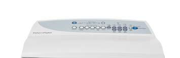
8 517790D 1.16 Water Conservation Rating* AAAA: A very high level of water efficiency *Issued by the Water Services Association of Australia 1.17 Fabric Softener Dispenser Dosage 75cc 1.18 Electric Supply Operating Voltage Maximum Current 1.19 User Guide User Guide /240V AC 50Hz 2.8 amps 1.20 Lid Lock Resistance 63Ω +/- 20 o C (68 o F) Note: Normally low voltage, potentially 230V if harness is grounded on the cabinet! 1.21 Control Panel - GW 1.22 Control Panel - MW 8


9 517790D 2 TECHNICAL OVERVIEW This Service Manual contains information on the Product Specifications, Diagnostic Mode, Detailed Fault Codes and the complete disassembly and assembly instructions for the Phase 7 SmartDrive washing machine. 2.1 Electronics Motor Control Module The Motor Control microprocessor performs a wide variety of tasks. Primarily it controls the electronic switching hardware to control the three phase currents in the Smart Drive DC motor. The micro can accurately control not only the velocity of the motor but also the acceleration. This accurate control is required to perform all the different agitator profiles, or wash actions, that are used for caring for clothes. The Motor Control module performs the functions of spin, fill, wash, drain and spray rinse when commanded to by the Display. The Motor Control module microprocessor has a wide range of control with great accuracy over spin speed, agitate action, fill temperature and water level. Having such control insures the wash cycle selected provides the optimum soil removal combined with appropriate gentleness for the washing and care of the clothes load. The Motor Control Modules for the Phase 7 Washers are air-cooled in the same way as the Phase 5, and 6 machines are, and are coloured brown, the same colour that is used for Phase 6, Series 11 & 12 machines. This Motor Control Module is not inter-changeable with other any other Phase or Series of machines. Identification The physical shape of the Motor Control Module is different to the Phase 6 machines. The Phase 7 module also has a yellow label attached to the top of the housing stating P7CP (Phase 7, Conventional Pump). Motor Control Module Phase 7 Identifier Label Motor Control Module Phase 6 Series 11 & 12 Note: When replacing a Motor Control Module ensure that the pressure tube is clear of any water droplets before operating the machine on a fill cycle. If the bowl is full of water drain the water then blow down the tube. 9

10 517790D Display Module The Display Module provides the link between the washing machine electronics and the user. Input on wash type, water level, spin speed, start/stop and wash cycle time is given by the user via the display push buttons. Feedback on selection is given to the user by Light Emitting Diodes (LEDs). Sound effects accompany button presses. 2.2 Stand By Mode If a Phase 7 machine has not received any instructions for 10 minutes after being switched on at the power point, or after completing the cycle, it will automatically go into a low power Stand By mode in the same way as the Series 9, 11 & 12 SmartDrives. The control panel will be blank as if it was powered off at the wall. Before entering the Diagnostic or Option Adjustment modes, the machine must be taken out of the Stand By mode. To do this, the POWER button will have to be pressed, or the machine turned off and back on at the power point. 2.3 Out of Balance Detection Bump Detect Past electronic machines have used a lever connected to a mechanical switch to detect if the load in the inner bowl is out of balance. On Phase 7 machines this system has been replaced with electronic sensing known as Bump Detect. Bump Detect is software written into the Motor Control Module, which looks at specific feedback from the Rotor Position Sensor. No fault codes are associated with Bump Detect, and there are no hard and fast tests that can be carried out. If a machine continually goes into an out of balance condition then the following needs to be checked in the order given. 1. Even distribution of the clothes load. 2. Ensure that the machine is both level and stable on the floor. 3. Check the weight of the inner bowl. Bowl weights are as follows: Compact: 7.303kg +/- 225g Medium: 9.225kg +/- 175g Large 10.48kg +/- 275g. 4. Check the RPS using a RPS Tester. Note: If the OOB problem persists after checking the above, we would then recommend replacing both the suspension rods and the rotor. It is highly unlikely that the Motor Control Module will be the cause. 10
11 517790D 2.4 Water Temperature Sensing GW Washer The thermistor for sensing water temperature in the GW Washer is located in the back of the outlet elbow on the valve assembly, and is connected directly to the Motor Control Module. For details on the wash temperature adjustment Refer to Section & Specifications NTC-type temperature sensor (Thermistor) Resistance 25 o C Thermistor MW Washer As there is no thermistor (temperature sensor) in the MW Washer the only temperature that can be adjusted is the warm wash temperature. The temperature of the warm wash is entirely dependent on a number of factors: a. Cold water temperature b. Cold water pressure c. Hot water temperature d. Hot water pressure. e. Warm wash setting. As the above will vary from installation to installation it would be impossible to predict what temperature each installation will ultimately achieve. However under the conditions outlined below, a temperature of between o C should be achieved. Cold water temperature: 20 o C Cold water pressure: 320 kpa (46.5 psi) Hot water temperature: 60 o C Hot water pressure: 320 kpa (46.5 psi) Warm wash setting: Default setting (9 min wash LED 3rd Green wash LED from the left). 11

12 517790D Warm Wash Temperature Adjustment (MW Only) The warm wash temperature adjustment will alter the amount of time that the hot valve pulses on and off for. 1. Turn machine on at the wall but do not press POWER. 2. Press START/PAUSE and hold down, then press POWER. Two quick beeps will be heard and the machine will show an unusual pattern of lights. In this mode the lights are used to indicate the different options available. 3. Select the Warm Wash Temperature. 4. Advancing the Wash Progress LED by pressing ADVANCE will increase the wash temperature. If the ADVANCE button is kept pressed, the light will scroll back to the coldest setting available for that wash temperature. 5. Press the POWER to lock in the setting. Note: If the required temperature still can t be obtained, advance the wash progress LED (as described in the procedure above) across to the spin LED and manually adjust the flow of the taps Wash Temperature Adjustment (GW Only) 1. Turn machine on at the wall but do not press POWER. 2. Press START/PAUSE and hold down, then press POWER. Two quick beeps will be heard and the machine will show an unusual pattern of lights. In this mode the lights are used to indicate the different options available. 3. Select the WASH TEMPERATURE to be adjusted. 4. The wash progress lights show the temperature adjustment possible for that temperature. Pressing the ADVANCE will cause the wash progress light that is on to change. Advancing the Wash Progress light will increase the wash temperature. If the ADVANCE button is kept pressed, the light will scroll back to the coldest setting available for that wash temperature 12


13 517790D Controlled Cold (GW Only) If the cold water temperature is very low (below 20 o C), a very effective wash will not be obtained. The controlled cold option solves this problem by adding a small amount of hot water to raise the temperature of the wash. We have called this Controlled Cold. 1. Turn machine on at the wall but do not press POWER. 2. Press START/PAUSE and hold down, then press POWER. Two quick beeps will be heard and the machine will show an unusual pattern of lights. In this mode the lights are used to indicate the different options available. 3. Select COLD wash temperature. 4. The Wash Progress lights show the temperature adjustment possible. When the first progress light is on, the machine will fill with cold water only. Press ADVANCE to select the second light and the SmartDrive will control the temperature to approximately 20 C. Each following light equals approximately a 1 C temperature rise. 2.5 Water Valves The Phase 7 machines use a new dual valve block assembly. Independent coils control the hot and cold water supply, which feeds the water through a common outlet. The GW valve block has a location feature for the thermistor. There is no thermistor location feature on the MW Washer. 2.6 Water Level Measurement SmartDrive is fitted with a pressure sensor, which can control the fill to any water level. The pressure sensor is incorporated within the Motor Control Module and cannot be removed. The pressure tube connects from the Motor Control Module to the air bell at the bottom of the outer bowl, and is part of the harness assembly. Care must be taken when removing or refitting the pressure tube to the pressure sensor as too much force can damage this device. 13
14 517790D Manual Water Level (MW & GW) The agitator has 5 levels marked on its stem that can be used to help the user select the correct water level. Select the correct water level by using the mark nearest to the top of the clothes. The levels marked on the agitator are a guide for the clothes and do not correspond exactly to the water level. SmartDrive may occasionally add water during agitation. This is to maintain the water level due to the release of air trapped in the garments. As the MW Washer only has 3 water levels (low, medium and high), if the garments sit between these levels we would recommend using a lower water level than that of the garments or more garments be added to the load. For example: If the garments sat between the medium and high marks on the agitator, choosing a medium water level would be better than choosing a high water level. Alternatively additional garments could be added so that the garments were brought closer to the high mark. High GW712 (54mm) GW612 (50mm) MW612 (50mm) GW512 (60mm) MW512 (60mm) Medium High GW712 (105mm) GW612 (110mm) GW512 (115mm) Medium GW712 (170mm) GW612 (175mm) MW612 (175mm) GW512 (180mm) MW512 (180mm) Medium Low GW712 (245mm) GW612 (250mm) GW512 (255mm) Low GW712 (300mm) GW612 (305mm) MW612 (50mm) GW512 (310mm) MW512 (310mm) SmartDrive Water Level Settings Tolerance for each water level = +/- 15mm Auto Water Level (GW only) SmartDrive automatically selects the appropriate water level for the load when AUTO Water Level is selected, and will choose one of the pre-existing 5 water levels (low, medium low, medium, medium high and high). During fill SmartDrive pauses occasionally to sense the water level. SmartDrive checks if the water level is correct by using a series of 2 different agitate strokes. A slow stroke to sense the load and an agitate stroke to mix the load. If SmartDrive detects that that water level is too low it will fill with more water and check the level again. When washing an unusual load eg. large bulky garments, pillows, it is recommend that the water level is manually selected. Manually select the water level if there is already water in the bowl. If SmartDrive does not fill to the correct level, the water level that SmartDrive selects can be modified using Option Adjustment Mode. 14

 Phase 7 Stator (36 Poles) Curved pole tips 2.7.2 Aluminium Stator Introduced April 2007 In April 2007 an aluminium wound stator was introduced to the MW & GW compact machines.")
15 517790D 2.7 Motor Copper Stator This stators used on the Phase 7 machines are unique to this Phase only and therefore it is not interchangeable with any previous phase or series of machines. The stator has 36 poles instead of 42 poles, and the pole tips are curved. The resistance of the windings remains the same as for the Phase 5, Series 9, and Phase 6, Series 11 and 12 machines at 16 ohms per winding. The rotor position sensor is also unique to this stator. (Refer to Section ) Phase 7 Stator (36 Poles) Curved pole tips Aluminium Stator Introduced April 2007 In April 2007 an aluminium wound stator was introduced to the MW & GW compact machines. As a result the service code changed from A to B. The aluminium stator must not be fitted to a GW Medium or GW Large, all Intuitive models or the AquaSmart machines. They also shouldn t be fitted GW Compact or MW Compact prior to the change, the reason for this is that the models which are produced with the aluminium stator, have also had changes to the software in the electronics. Visually the aluminium stator is similar to that of the copper stator however the resistances between them are different (Refer to the wiring diagram below). RED BLUE YELLOW Wiring Diagram RED BLUE YELLOW Ω 51Ω Ω STAR POINT STAR POINT Ω Ω 32 Copper Stator 51Ω 32 Aluminium Stator (MW & GW Compact Machines only) 15
. Note: Ensure that the Rotor or bowl is stationary when measurements are made.")
16 517790D Testing the Stator If the stator needs to be tested we would first recommend testing the resistance of the windings from the harness that is connected to the Motor Control Module. (Refer to Section 7). Note: Ensure that the Rotor or bowl is stationary when measurements are made. Testing the stator from the console The resistance of each individual winding is approximately 16 ohms (25.5 ohms aluminium stator), however when testing the stator from the console we are testing across two windings therefore the resistance should be approx 32 ohms (25.5 ohms aluminium stator) +/- 10%. To test all windings you will need to measure across: Red & Blue Red & Yellow Blue & Yellow If the meter shows an incorrect reading we would then recommend testing the stator from underneath the machine as there could be a fault in the wiring harness. To test the stator, both rotor and stator need to be removed. Refer to Sections and Note: Two clamp plates are used to secure the Stator, one on each side. The four bolts are tightened to a torque of 5 Nm. The plastic bolt for securing the Rotor requires a 16mm socket and should be tightened to 8 Nm. Testing the Stator After removing the Stator, it can now be tested. Test points are: Red / Blue Red / Yellow Blue / Yellow The value should be approx 32Ω (25.5 ohms aluminium stator) +/- 10% across any of the two windings Ω Rotor The rotor is also unique to the Phase 7 machines. It has 16 blocks containing 3 individual magnets, as opposed to 14 blocks, containing 4 magnets for Phase 5, and Phase 6 machines. The rotors between Phase 7 and previous Phases of machines can physically be interchanged, however electrically they are incompatible. If a Phase 7 rotor is fitted to a Phase 6 or earlier machine, fault code 240 will occur. Conversely fault code 240 will also occur if a rotor from a Phase 6 or earlier machine is fitted to a Phase 7 machine. Apart from the number of magnets the other (and easiest) way to identify the Phase 7 rotor is by the number of holes. The Phase 7 rotor has larger holes around the outer perimeter and an additional set of large holes on the inner perimeter. 16


17 517790D The photographs below show the difference between a Phase 7, and a Phase 6 Rotor. Phase 7 Phase Rotor Position Sensor (RPS) One of the inputs that the Motor Control Module module needs in order to determine which switches to turn on is the position of the rotor. The rotor position sensor (RPS) supplies this information. The RPS is a printed circuit board that contains three Hall Sensors. These detect the magnetic field of the individual magnets in the rotor. As the motor turns, the position of a group of magnets is detected. There are 5 wires on the RPS, 2 for power supply and 3 signal wires. Data on the position of the rotor is supplied to the microprocessor in the Motor Control Module module via the three signal wires. The printed circuit board sits in a plastic housing encapsulated by resin to protect the board. The only exposed area of the board is the connector for the main harness. 17

18 517790D Testing the Rotor Position Sensor To test the RPS use a RPS tester, part number , which is powered by a 9V battery. To test the RPS of a Phase 7 Washer it will also require an adaptor harness, part number The tester has 3 LEDs, and the pattern of these LEDs will change as the magnetic field of the Rotor passes the hall sensors. Connect the RPS tester to the RPS harness. Turn the bowl and note the pattern of lights. A valid pattern is a pass. A fail will indicate a failure of either the harness or the RPS. If a failed pattern is showing, connect the RPS tester directly on to the RPS and retest. A pass is when 1 or 2 LEDs are illuminated at a time, 0 or 3 LEDs illuminated indicates fail. Any flickering of the fail LED will indicate that the RPS or rotor is faulty. A faulty rotor would give a fail at certain points of rotation. Note: This tester does not test all the functionality of the RPS. It tests the 3 outputs but cannot indicate all faults, for example if a capacitor on the RPS is cracked. The rotor may also be tested with a RPS Tester. A complete rotation will test all the magnets. If the rotor has cracked or chipped magnets it will work fine, and does not need to be replaced. 2.8 Pump The pump is coupled directly to the outer bowl. This eliminates bowl to pump hoses and the accompanying seals, clips etc. The pump housing is an integral part of the outer bowl. When removing the pump up to a litre of water may leak from the pump cavity. When refitting the pump lubricate the seal face with liquid soap or detergent (do not use grease). Blocked Pump Detection This is achieved by monitoring the water level during drain. If the water level has not dropped by approximately 3mm within a predetermined time period (approximately 9-10 minutes), then the product will report a blocked pump fault. 18

19 517790D 2.9 Lid Lock The Phase 7 Washer uses the same lid lock that is used on the Phase 6 series 11 & 12 machines. During the spin and drain out part of the cycle prior to spray rinse, the lid will lock down until the completion of the spin. Once the spin has completed, the lock will release and the lid can be opened. The Lid Locked LED will illuminate on the GW and MW machines. If the lid is left open, the machine will be unable to lock the lid and the cycle will be halted. The machine will play a tune and the lid lock will flash until the lid is closed and START/PAUSE is pressed. If the lid-lock fails in the closed position, the locked lid can be forced upwards and out of the lock. Note: This is the only time in which we would recommend doing this. If the harness is damaged, the complete lid lock assembly will need to be replaced. The chart below shows the stages when the lid is locked. If the power supply is cut during the spin cycle, the machine will keep the lid locked until the rotor has ceased to turn (3 to 10 secs). Only then will it release the lock. The motor is acting like a generator and allows the lock to stay energised under the bowls inertia. Fill Agitate Spray Rinse Deep Rinse Spin Unlocked Unlocked Locked Unlocked Locked In a brown out situation, the machine will restart at the start of whatever section of the cycle it was on and continue the wash. The lid lock would then be reactivated if it happened to be on a spin cycle. 19

20 517790D 2.10 Inner and Outer Bowls The outer bowl is the assembly to which all the motor, pump system, suspension rods, etc are mounted. Within the outer bowl are the inner bowl and the agitator. During spin, the agitator and inner bowl have to be coupled together and turn as a single unit. In agitate, the agitator and inner bowl are free to rotate independently. In SmartDrive the inner bowl is free to move in a vertical direction. The position of the inner bowl is determined by the water level. At the base of the inner bowl is a flotation chamber consisting of a number of individual cells. When SmartDrive is filling with water, the pressure on the air in these cells increases as the water level rises until eventually the inner bowl floats upwards and disengages the driven spline from the drive spline. This action frees the agitator from the inner bowl and allows it to move freely in both directions. When the water is draining from SmartDrive, the pressure on the air trapped in the cells of the flotation chamber decreases allowing the inner bowl to settle back down onto the drive spline and re-engage the driven spline, thus allowing the agitator and inner bowl to turn as one unit. The floating bowl is also used to detect if the user has selected the correct water level for the size of the clothes load in SmartDrive. The point at which the bowl starts to float is determined by the water level and the size of the load. The greater the load, the more water is needed before the inner bowl will float. By detecting the point at which the bowl floats, SmartDrive can determine whether the correct water level for the particular clothes load has been chosen by the operator. If the operator has chosen a level that is too low for the load, SmartDrive will override that choice and fill to the correct level. This is to ensure optimum wash performance and minimal clothes wear. If the user has selected a level that is higher than necessary, SmartDrive will still fill to the users selected level Detection Of Inner Bowl Float Off Point Bowl Check During fill the inner bowl will rotate to ensure that the clothes are evenly saturated with water. When the chosen water level is reached, and before the agitate cycle is started, SmartDrive will carry out inner bowl float checks (bowl check). The inner bowl will stop and commence a number of small agitate type actions. During this action SmartDrive determines if the inner bowl has floated. If it has, SmartDrive will determine the required water level and check if the operator has selected the correct level. If the inner bowl has not floated, SmartDrive will continue filling and check again later. The water level at which the inner bowl floats is not necessarily the same as the final water level. 20
21 517790D Detection of Inner Bowl Re-Engagement Bowl Check After SmartDrive has pumped out the water, the inner bowl will sink down and re-engage onto the drive spline. To ensure the inner bowl has re-engaged correctly, SmartDrive will carry out a bowl re-engage test sequence (bowl check). Bowl check consists of a series of short agitate type actions before the spin cycle starts. A sound may be heard as the inner bowl re-engages Balance Rings The inner bowl has 2 balance rings, one at the top, and one at the bottom. These are sealed compartments half full of water. This water allows the bowl to balance. If one or both of these rings have lost water then the inner bowl must be replaced. The easiest way to determine a loss of water is to weigh the bowls on n accurate set of scales. Inner Bowl Weights Compact Medium Large 7.303kg +/- 225g 9.225kg +/- 175g kg +/- 275g 2.11 Agitator Smart Drive s agitator design differs from conventional designs in that it is made of very flexible plastic that bends and flexes as the clothes are moved around the bowl. The agitator action is similar to that of a fish moving through the water, so the side-wards motion is translated to forward thrust. This is not only more forgiving on the clothes but helps to slowly move the clothes around the bowl in a toroidal motion, ie. a vertical circular motion. The fins at the top of the agitator pull the clothes on the surface of the water inwards and then push them downwards. The bottom fins then push the clothes towards the outside of the bowl again and back up to the surface. The agitator also features guides on the side to help the user choose the correct water level for each load size. The guides relate to the level that the dry clothes come up to, which relates back to the correct water level. The agitator also gives the user information when measuring detergent, to ensure that they dose correctly for the load size Lint Removal System Smart Drive s self cleaning lint removal system works by continuous water circulation, resulting in the separation of lint from the wash water. As the agitator moves, the specially designed vanes on the bottom create turbulence. The agitator acts as a centrifugal pump, circulating the wash water. As a result of the agitator action, lint and wash water are sucked into the agitator stem and down to the base where they are directed into the cavity between the inner and outer bowls. The extruded holes of the inner bowl are shaped to allow the wash water to flow back into the bowl, but prevent the lint from following. The lint then floats to the surface of the water between the inner and outer bowl and remains there until it is flushed out the drain at the end of the wash cycle. 21
22 517790D 2.13 Fabric Softener Dispensing TYPE: It is recommended that softener sheets should be used in the dryer rather than using liquid softener in the washing machine. Liquid softener has been known to produce a waxy build-up inside washing machines, called Scrud. We do however, provide a fabric softener dispenser for those who prefer liquids. It is recommended thinner varieties be used over thicker ones as they dispense more cleanly. WHERE: The liquid fabric softener goes in the dispenser cup on top of the agitator. The fabric softener is automatically dispensed into the final deep rinse. In this way the fabric softener and detergent are separated, as they are not compatible. Pour fabric softener into the dispenser as shown Here's how it works on the Heavy Duty, Regular and Wool Cycles. 1. Fabric softener remains in the dispenser cup during the fill, agitate and drain phase of the wash program. 2. During the first phase of the spray rinse it is centrifuged out of the cup into the body of the dispenser. 3. The fabric softener is held hard up against the sides of the dispenser body by centrifugal force throughout the spray rinse. 4. At the end of spray rinse the softener drains out of the dispenser, down the centre of the agitator where it is dissolved in the incoming deep rinse water. For the Delicate and Permanent Press cycles the fabric softener remains in the dispenser cup throughout the wash and first deep rinse. SmartDrive then spins to release the fabric softener, delivering it down the agitator stem as SmartDrive fills for the final rinse. 22
23 517790D Scrud If fabric softener is used regularly it will eventually cause a build up within the outer bowl. This can result in black flakes present in the wash load that can stain garments. To remove scrud follow the procedure below. Step1: Add a full cup of a good quality dishwashing powder such as Active or a similar product into the machine. Step 2: Set the machine to a Heavy Duty cycle, select a Hot Wash temperature, High Water level and allow the machine to agitate for 10 minutes. Step 3: Leaving the lid closed, turn the machine off and allow to soak overnight. Step 4: The following day, turn the machine on and advance to the spin cycle to drain the water from the machine. After the water has drained, turn the machine off then back on again, and select a Heavy Duty cycle, Hot wash, High Water level, and allow the machine to complete a full cycle to ensure that all of the loose scrud and residual detergent has been flushed away. Note: If there is an extremely heavy build up the above procedure may have to be repeated. 23
24 517790D 3 SIZE SETTING MODE To set the size switch, turn the power on at the power point and off at the console. Press and hold WASH TEMPERATURE SETTING UP then press POWER. SmartDrive will give 4 short beeps and the pattern of LEDs will change. One of the following buttons needs to be pushed to lock the size into memory. Press WASH TEMPERATURE SETTING UP, the COLD LED is on for 5.5kg (560mm wide). Press WATER LEVEL UP, the LOW WATER LED is on for 6.5kg / 7.0kg (600mm wide). Press SPIN SPEED UP, the SPIN HOLD LED is on for 7.5 / 8.0kg (650mm wide). Press POWER to confirm the setting and also exit this mode. If the size setting is wrong, SmartDrive will have the following settings incorrect: - The Auto Water Levels chosen may be incorrect. The High Water Level may be incorrect by as much as 40mm. The wash profiles may be incorrect resulting in poor wash performance or vigorous wash actions causing tangling, splash over or excess linting. Water saver settings. 4 DIAGNOSTIC MODE To enter diagnostic mode follow the steps below. 1. Turn the power on at the power point but off at the machine. 2. Press and hold WASH TEMPERATURE SETTING DOWN and then press POWER until the machine gives 2 short beeps and lights up. 3. Release the buttons after the beeps as the beeps indicate diagnostic mode has been entered. 4.1 Last Fault Data When in diagnostic mode the last fault can be found by pressing the SPIN SPEED UP or DOWN buttons until the HOLD and SLOW lights are illuminated. Binary can then be read from the wash progress lights Drain Pump Test MW Washer When in diagnostic mode press SMART TOUCH CYCLES to activate the drain pump. To deactivate the pump, press SMART TOUCH CYCLES again. GW Washer When in diagnostic mode press REGULAR to activate the drain pump. To deactivate the pump, press REGULAR again. 24
25 517790D 4.3 Water Valve Test The water valves can be activated in diagnostic mode by pushing WASH TEMPERATURE SETTING UP to activate the Hot Valve and WASH TEMPERATURE SETTING DOWN to activate the Cold valve as with previous models. Pressing each button once will activate the valve. To de-activate valve press the same button again. This is also good to use when installing machines as it takes the shock out of the fittings and seals and allows checking for leaks on the inlet hoses, both machine end and tap or super-tub end. Caution: Do not leave the machine unattended when either or both valves are operating. 4.4 Restart Feature If a fault occurs in the machine, the diagnostic system will detect it. However, instead of displaying a fault code immediately, the machine will try to restart. If the fault was only of temporary nature, the machine will restart and finish the cycle. If there is a continuous fault the machine will try to restart a number of times. This process could take up to 8 minutes depending on the type of fault. After this, if the machine still cannot restart, the fault code is displayed and the machine will beep continuously. The number of retries will depend on the fault that it has detected, however the maximum number or retries for any one fault is 32 times. The restart feature is turned on when a machine leaves the factory. For servicing we strongly recommend that this feature be disabled. To turn the restart feature on follow the procedures below: 1. Enter diagnostic mode (Refer to Section 4). 2. Press WATER LEVEL DOWN so that the low water level LED is lit. 3. Press POWER to turn the display off (the 5 leftmost wash progress LEDs will be flashing). 4. Press POWER to turn the machine on. 5. The machine can now be tested on any cycle. To turn the restart feature off, either repeat the steps above or switch off the power to the machine. The restart feature can be permanently programmed in to the machine s memory. When in diagnostic mode press and hold ADVANCE down at the same time as pressing WATER LEVEL DOWN. A long beep will acknowledge the setting has been retained in EEPROM. Press POWER to retain selection as with size switching. To remove from the permanent memory, repeat the above procedure. Note: This feature is designed as a service aid only and should be left on in the customer s home. To return to normal operation, and to reset the restart feature to the factory setting, switch the machine off at the wall or disconnect from the mains supply. 4.5 Recycle Feature The recycle feature, when enabled, will cause the machine to continuously repeat the cycle that has been selected. At the completion of the spin cycle the machine will power off briefly then power back up again and will start the cycle programmed. This feature would be useful to help identify an intermittent problem, and would be best used if the machine had been taken back to a workshop for service. 25
26 517790D To turn the recycle feature on follow the procedures below: 1. Enter diagnostic mode (Refer to Section 4). 2. Press WATER LEVEL UP so that the Medium water level LED is lit. 3. Press POWER to turn the display off (the 3 rightmost wash progress LEDs will be flashing). 4. Press POWER to turn the machine on. The machine can now be tested on any cycle. Note: This feature is designed as a service aid only and should be OFF in the customer s home. To return to normal operation, and to return the recycle feature to the factory setting, switch the machine off at the wall or disconnect from the mains supply. 4.6 Hot Bowl Flag If a SmartDrive machine has been filled with hot water and has not had a cold rinse, it will not spin up to its full speed of 1000 RPM. Its maximum speed will instead be restricted to a maximum of 700 RPM. This is to prevent distortion of any internal plastic componentry that may occur at a high spin speed. The hot bowl flag works the same for the GW as it does for the MW, however as the MW does not have as many LEDs as the GW, the hot bowl flag is not visible unless a GW display is fitted. To check to see if this flag has been enacted, firstly enter diagnostic mode (Refer to Section 4). The LED adjacent to WATER SAVER will be lit. To clear this flag and allow SmartDrive to spin to 1000RPM: GW Washer: Either press the OPTIONS button while in diagnostic mode, or put SmartDrive through a complete final rinse. MW Washer: Put SmartDrive through a complete final rinse or plug in a GW display module and clear through diagnostics as described above. 4.7 Data Download Enter diagnostic mode. Press START/PAUSE. The Lid Lock LED will now be on and flickering. Place the download pen over this LED and follow the instructions supplied with the data download programme. 4.8 User Warnings There are a number of warnings which are generally caused by the user or poor installation. These warnings should be able to be corrected by the user. SmartDrive signals user warnings by flashing LEDs and a rippling set of 5 beeps repeated every 6 seconds. This is the same tone that is heard when SmartDrive is first plugged into the mains power. Most of this information is available to the user in the Use and Care Manual. 26
27 517790D Hot Water Temperature LED Flashing (Insufficient Hot Water) - GW Machine only Possible causes: 1. Check that the hot water is connected and that the tap is turned on. 2. Check that the water temperature is not too low. The water temperature may need to be 60 o C for a hot wash. 3. Check that the hot water inlet hose is not connected to the cold water supply. 4. Check that there are no kinks in the inlet hoses. 5. Check that the filter on the hot inlet hose at the tap end is not blocked. 6. Check that the filter screen in the hot inlet valve is not blocked. 7. Check the resistance of the thermistor. Resistance is 25oC. Replace if well outside of this range. 8. Check the size is set correctly. Note: If the machine is set to controlled cold, hot water may be required to achieve 20 o C Cold Water Temperature LED Flashing (Insufficient Cold Water) - GW Machine only Possible causes: 1. Check that the cold water is connected and that the tap is turned on. 2. Check that the flow rate is not too low. The product requires a minimum flow rate of 3 litres per minute. 3. Check that the cold water inlet hose is not connected to the hot water supply. 4. Check that there are no kinks in the inlet hoses. 5. Check that the filter on the cold inlet hose at the tap end is not blocked. 6. Check that the filter screen in the cold inlet valve is not blocked. 7. Check the resistance of the thermistor. Resistance is 25oC. Replace if well outside of this range. 8. Check the size is set correctly Hot & Cold Water Temperature LED s Flashing (No Water) Possible causes: 1. Check that water is connected and that the taps are turned on. 2. Check that there are no kinks in the inlet hoses. 3. Check that the filters on the inlet hoses at the tap end are not blocked. 4. Check that the filter screens in the inlet valves are not blocked. 5. Check that the flow rate is not too low. The product requires a minimum flow rate of 3 litres per minute. 6. Check that the drain hose is not too low or the drain hose is not pushed into the standpipe too far and the water is siphoning out of the machine. 7. Check the size is set correctly High Water Level LED Flashing (Overloaded Product) Possible causes: 1. Check that the product is not overloaded. 2. Check the user has not selected the wrong water level. 3. Check that the rotating bowl assembly is not jammed to the agitator with any foreign object that may be caught under the agitator skirt. 4. Check that the clutch teeth are not locked together with dirt, detergent or lint. Check that the teeth are not broken. 27
28 517790D First Rinse or Final Spin and Current Spin Speed LED Flashing (Out of Balance) Possible causes: 1. Check that SmartDrive is correctly installed, is level and does not rock on the floor. 2. Check the bias spring is fitted between the top of the neck ring and the front left hand suspension rod. 3. Check the suspension is not catching or bouncy. If so, replace all four suspension rods. 4. Check both balance rings on the inner bowl contain water. The most accurate way is to check the weight of the inner bowl (Refer to Section 1.12). 5. Check that the holes on the inner bowl have been punched through or are not blocked Suds (First Rinse LED is flashing or Final Spin LED is flashing) This warning is generated if the SmartDrive senses too much drag on the inner bowl. 1. Too much detergent generally causes this. If so, dissolve the suds by flushing water through the machine and re-test. 2. Check that the pump is not partially blocked, or that the drain hose is not kinked. 3. Check that a garment or foreign object is not restricting the movement of the inner bowl. 4. Check that the main bearings are not tight Lid Lock LED Flashing This warning is generated if the electronics have detected that the lid has not been closed. 1. Check that the tang on the lid is not bent or broken. 2. If the lid is closed and the tang is ok, replace the lid-lock assembly Demonstration Mode (All LEDs flashing in patterns) This feature is designed for in store demonstration purposes. SmartDrive can draw attention to itself with a selection of flashing LEDs. In this mode SmartDrive cannot be started. To Select demonstration mode press and hold Advance, then press Power. During demonstration mode the LEDs will alternate between all on, LEDs flashing, and all LEDs off. To return SmartDrive to normal operation, the mains supply must be switched off. 4.9 SmartDrive Diagnostic Table To use this table, firstly enter Diagnostic Mode (Refer to Section 4). The different levels of information can be extracted by using the Spin Speed up and down buttons. Diagnostic Spin Speed LEDs Diagnostic Info Displayed Level Fast Med Slow Hold 0 OFF OFF OFF OFF Last User Warning Number 1 OFF OFF OFF ON Last User Warning Cycle Position 2 OFF OFF ON OFF Factory use only Not applicable to the field 3 OFF OFF ON ON Fault Code at last fault (if within the last 8 cycles) 4 OFF ON OFF OFF Factory use only Not applicable to the field 5 OFF ON OFF ON Cycle count at last fault (low byte) 6 OFF ON ON OFF Cycle count at last fault (high byte) 7 OFF ON ON ON Cycle position at last fault 8 ON OFF OFF OFF Water Temp (deg C) 9 ON OFF OFF ON Cycle count (low byte) 10 ON OFF ON OFF Cycle count (high byte) 11 ON OFF ON ON Motor speed (RPM) 12 ON ON OFF OFF Water Level 13 ON ON OFF ON EEPROM version number 14 ON ON ON OFF Factory use only Not applicable to the field 15 ON ON ON ON Factory use only Not applicable to the field 28
29 517790D Diagnostic mode 0, Last User Warning Number: When in this level, use the binary count on the Wash Progress LEDs as used to obtain the last fault data. Use the chart below to identify which was the last user warning. Binary Count User Warning 0 No warning 1 No taps 2 Overload 3 OOB 4 Suds 5 No Hot 6 No Cold 7 Agitate overloaded Diagnostic mode 1: Last User Warning Cycle Position To find out which stage in the cycle the last user warning occurred, use this level. A LED on the wash progress LEDs will identify the stage, ie if the user warning was suds (in diagnostic level 0) and the 1 st Rinse LED was lit in this level, this was the stage in the cycle where the user warning occurred. Diagnostic mode 3: Last fault data This level is sometimes referred to as the detailed fault code. By adding up the LEDs on the wash progress in binary form (Refer to Section 4), this will relate to a fault code (fault codes are contained in the last section of this manual). If there are no LEDs lit, a fault code hasn t occurred in the last 8 cycles. Diagnostic mode 5&6: Cycle count at last fault (Low byte, High byte). These levels will indicate how many cycles ago the last fault occurred. Even though the last fault gets wiped from diagnostic level 3 after 8 cycles, the cycle where the fault occurred is permanently stored in the memory. The low byte refers to binary numbers from 1 through to 128. The high byte Refers to numbers from 256 though to It always pays to check the low and high bytes. Diagnostic mode 7: Cycle position at last fault An LED that is illuminated on the Wash Progress will indicate the cycle where the last fault occurred. Diagnostic mode 8: Water Temperature (deg C) By adding up the LEDs on the wash progress in binary form (Refer to Section 4), this will give the temperature of the thermistor in O C. Note: This feature is not available on the MW model, as there it has no thermistor. Diagnostic mode 9 & 10: Cycle count low byte & high byte These levels work in the same way as for Diagnostic levels 5&6, which allows the Service Technician to establish how many cycles the machine has completed. Note: A completed cycle is counted at the end of the spin cycle. Diagnostic mode 11: Motor Speed (RPM) Add up the LEDs on the wash progress, and multiply this figure by 10. The result will give the spin speed in RPM. Diagnostic mode 12: Water Level Add up the LEDs on the wash progress, and multiply this amount by 2. The result will give a reading of the water level in millimetres. 29
30 5 WIRING DIAGRAM 30
31 6 VOLTAGE READINGS FROM CONTROLLER Water Valves Varies between 13 22V DC Note: Accurate voltages can only be obtained by using a True RMS multimeter. 2. Supply voltage 230 VAC 3. Wash Motor No accurate readings are possible. 4. Pump Motor 230V AC 6. Display Module 7. Lid lock 0 5 V DC Pulses up to 30V when locking, when locked, sits at approx 10V DC 5. RPS Individual phases will be 15 or 0 volts, will change as motor turns 8. Thermistor 5 V DC C B A Should always be 15V DC 31
 32Ω across any two windings 3. Pump Motor 6. Thermistor 10,000Ω @ 25oC 33Ω 4.")
32 7 RESISTANCE READINGS FROM CONTROLLER Water Valves 64 Ω +/- 10% 2. Wash Motor 5. Lid lock 63Ω +/- 20 o C (68 o F) 32Ω across any two windings 3. Pump Motor 6. Thermistor 25oC 33Ω 4. RPS - Unable to be tested with multimeter. 32
33 8 BINARY DECODING CHART 8 BITS (0-255) WASH PROGRESS LEDs short wash rinse spin ΟΟΟ ΟΟ Ο Ο Ο ΟΟ Ο Ο ΟΟΟΟΟ ΟΟΟΟ ΟΟΟ Ο ΟΟΟ ΟΟ ΟΟ ΟΟ Ο ΟΟ Ο ΟΟ Ο ΟΟΟ Ο ΟΟ Ο Ο Ο Ο Ο Ο ΟΟ Ο Ο Ο Ο Ο ΟΟΟΟ ΟΟΟ ΟΟ Ο ΟΟ Ο ΟΟ Ο Ο Ο Ο Ο ΟΟΟ ΟΟ Ο Ο Ο ΟΟ Ο Ο The above table shows the 8 wash progress LEDs with the SPIN LED corresponding to the LED on the far right hand side. 8 bit binary calculations: Least Significant Byte (LSB) is the SPIN LED. If it is on this has a value of 1. The Most Significant Byte (MSB) is the first wash LED, this has a value of 128 if it is on. The intermediate LEDs have values of 64, 32, 16, 8,4 and 2. By adding up the value of all the LEDs that are illuminated the 8 bit binary value may be calculated. Note: If the Spin LED is optically downloading it will be flickering, this does not necessarily count as part of the 8 bit value. To calculate a 16 bit value (eg. cycle count) TOTAL = (high byte x256) + (low byte). 33
34 9 DETAILED FAULT CODES INTRODUCTION PHASE 7 DETAILED FAULT CODES The format for fault description in this booklet follows the Primary, Secondary, Tertiary and Quaternary fault source system. These sources have mostly been arranged in order of most likely source of fault, but in some cases the sequence has been modified to aid the servicing procedure. It should be noted that the fault source Pump System includes the pump and drain hose assembly. These fault codes are specific to the Phase 7 machines. Fault code shows the last recorded fault. Always confirm fault. 9.1 FAULT DESCRIPTIONS 1. ( ) Motor Control Module Fault The Motor Control Module has encountered an error when writing to an EEPROM address. Primary Source: Motor Control Module. Replace Motor Control Module. 3. ( ) Motor Control Module Fault The Motor Control Module has found a memory error. Primary Source: Motor Control Module. Replace Motor Control Module. 9. ( ) Size Switch Error The Display size switch setting does not match that which is stored in memory. Action GW Machines: Reselect the size of the machine by using the SIZE SETTING MODE. To set the size switch, turn the power on at the power point and off at the console. Press and hold Wash Temperature Setting Up then press Power. SmartDrive will give 4 short beeps and the pattern of LEDs will change. One of the following buttons needs to be pushed to lock the size into memory. Press Wash Temperature Setting Up, the Cold LED is on for 5.5kg (560mm wide). Press Water Level Up, the Low Water LED is on for 6.5kg / 7.0kg (600mm wide). 34
35 Press Spin Speed Up, the Spin Hold LED is on for 7.5 / 8.0kg (650mm wide). Press Power to confirm the setting and also exit this mode. Action IW Machines: To access Size Setting Mode, push and hold the Fabric Care button and then press the Power button to enter Size Setting mode. Select the correct size on the display by pushing the Adjust button to highlight the correct size. Size setting is then achieved by pressing the Power button. Powering off will set the size into the memory. Note: Fault code 9 will only be logged into the memory of IW machines. GW and MW machines can display this fault but it will not be recorded. 10. ( ) Temperature Sensor (Thermistor) Error The temperature sensor may be open circuit or the ambient temperature is below minus 10 o C. This fault is only applicable in the GW models. Primary Source: Thermistor Secondary Source Motor Control Module 1. Check the connection of the thermistor to the Motor Control Module. 2. Check resistance of temperature sensor. Resistance should be 10k 25 o C or 12.5k 20 o C. Replace if faulty. 3. Replace Motor Control Module. 12. ( ) Flood Protection Error The Motor Control Module has found the water level to be above the flood level and tried to pump the excess water out. (Under extremely high flow rate conditions the machine may overfill during the top-up routine in agitate.) After pumping for 30 seconds, it has been unable to lower the water level below the flood level. Either the water valves have stuck on and are letting water in at a flow rate that is higher than the pump can handle, or the pump is blocked and can t remove the excess water. Primary Source: Water Valves. If the water valves are on continuously, check that the water valves turn off mechanically (remove power from machine). Secondary Source: Pump system. Check the pump for blockages and drain hose for correct height and kinking Tertiary Source: Motor Control Module. If water valves are being driven on electrically, replace Motor Control Module. 26. ( ) Detergent Valve Fault The Motor Control Module has measured a voltage from the valve diagnostic circuit that indicates the detergent valve (with Purple Clip) is faulty. The most likely cause is that the valve harness has not been connected correctly or the valve is open circuit. See fault code 49 for service procedure. 27. ( ) Fabric Softener Valve Fault The Motor Control Module has measured a voltage from the valve diagnostic circuit that indicates the fabric softener valve (with Yellow Clip) is faulty. The most likely cause is that the valve harness has not been connected correctly or the valve is open circuit. See fault code 49 for service procedure. 36. ( ) Water Leak Fault The Motor Control Module has needed to top up the water level more than 4 times during agitate. This is excessive, as normally only one or two top ups are required to replace the air that has escaped from a full load during agitate. The most likely cause is that the machine is siphoning. The other alternative is that the machine has developed a leak. Primary Source: Pump System. 35
36 Action Secondary Source: Mechanical. Tertiary Source: 1) Check the height of the drain hose outlet. Minimum 850mm, maximum 1200mm. 2) Check that the hose guide is fitted and check that the hose does not protrude more than 20mm beyond the guide. 1) Check the pressure tube connections on the outer bowl and Motor Control Module. 2) Check that the drive shaft seal and the pump housing seal have not developed a leak. Motor Control Module. Replace Motor Control Module. 37. ( ) Pump Blocked Error (No change in the water level) While draining, the water level reading from the pressure sensor has not changed for over 3 minutes. There are three likely reasons for this fault. One is that the drain hose or the pressure switch hose has been squashed or kinked and the pump out rate has been dramatically reduced. The second possibility is that the pump is partially or fully blocked. The third is that the pump is not operating due to Motor Control Module, wiring or pump failure. This fault could also appear if the machine is pumping to an unusually high head of drain hose or into an extended length of drain hose. The fourth possibility is a diverter valve fault or blockage, water level is not altering as the diverter is stuck in the recirculation mode, giving the module the appearance the pump is not lowering the water level. Primary Source: Secondary Source: Wiring. Pump System. 1) Check that the drain hose has not been kinked. 2) Check the length of the drain hose and try to reduce the length if excessively long. A 1-metre extension hose of the same diameter fitted to the existing drain hose is the maximum allowable length. 3) Check for open circuit windings in the pump. (Note: Pumps are fitted with a thermal cut-out, which will reset on cooling.) 4) If the bowl is empty of water, remove the pump from the pump housing and check that it is not blocked. Also check the drain hose is not blocked. 5) If the bowl contains water, then service the pump from the top of the machine by removing the top deck and inner bowl. Bail out the water, remove the pump cap and hood and clear the restriction. 1) Check the pump harness is connected correctly to the pump. 2) Check continuity of the pump harness. Tertiary Source: Motor Control Module. Activate the pump by operating the machine in spin mode. Check the pump is rotating. If it is not operating, and Primary and Secondary checks have been performed, then replace the Motor Control Module. 38. ( ) Pressure Sensor Fault The Motor Control Module has recorded a water level of empty while it is agitating. The water level must have been greater than empty for the machine to enter the agitate mode initially. The most likely cause of this fault is that the pressure sensor hose has been severed or fallen off during agitate. Alternatively, the pressure sensor may be faulty. Primary Source: Mechanical. Check that the pressure tube is intact and has not been cut. Secondary Source: Motor Control Module. Replace the Motor Control Module if the pressure tube shows no sign of being faulty. 36
37 39. ( ) Pressure Tube Fault The probable cause of this fault is that the pressure tube has become blocked or kinked or has fallen off completely. Alternatively, the pressure sensor may be faulty. Primary Source: Mechanical. Check that the pressure tube is intact and not blocked with water or dirt and is not kinked. Secondary Source: Motor Control Module. Replace the Motor Control Module. 40. ( ) Bowl Dis-engage Fault While carrying out a bowl check, the Motor Control Module has found that the bowl is not engaged even though the pressure sensor indicates that the bowl is empty. The Motor Control Module continues to check for 2 minutes, after which time it displays this fault. The first two areas to check are the clutch and the pressure tube. If these two appear correct, then the fault could be in the pressure sensor in the Motor Control Module. Primary Source: Mechanical. 1) Check that there are no clothes or other foreign objects preventing the clutch from re-engaging. Excessive suds can stop the bowl rotating. 2) If the machine is empty of water, carry out a clutch disassembly procedure and check the spline drive. 3) Next check that the pressure tube has not come off and that it is not kinked. Secondary Source: Motor Control Module. Replace Motor Control Module. 41. ( ) Temperature Sensor Fault (Thermistor) The temperature sensor is measuring temperatures above 110 o C. The fault is probably due to a short circuit in the sensor line. This fault is only applicable in the GW models. Primary Source: Thermistor. 1) Check the connection from the thermistor the Motor Control Module 2) Check the resistance of the thermistor. It should read 12.5k ohms at 20 o C. Replace if faulty. 3) Replace the Motor Control Module. 45. ( ) Display Memory Check Fault On power up, the display has checked its memory against a known reference and found differences. Primary Source: Display Module. Replace Display Module. 46. ( ) Display Memory EEPROM Check The Intuitive Display has detected a problem with its internal EEPROM. Primary Source: Display Module. Replace Display Module. 49. ( ) Cold Valve or Cold Valve & Hot Valve Faulty The Motor Control Module has measured a voltage from the valve diagnostic circuit that indicates the cold valve or both the cold and hot valve is faulty. The most likely cause is that the valve harness has not been connected correctly or the valve(s) is open circuit. Primary Source: Wiring. Check the valve harnesses are correctly fastened to the valves and the motor control module or the pins are not bent backwards. Secondary Source: Water Valves. Measure the resistance of the cold and hot valve coils. Tertiary Source: Motor Control module. Replace the Motor Control module. 37
38 50. ( ) Hot Valve Faulty The Motor Control Module has measured a voltage from the valve diagnostic circuit that indicates the hot valve is faulty. The most likely cause is that the valve harness has not been connected correctly or the valve is open circuit. See fault 48 for service procedure. 51. ( ) Diverter Valve Fault The motor controller has registered a drop in water level in the recirculation phase of the wash cycle. Water is being drained instead of recirculated. Primary Source: Diverter valve. Remove the diverter valve and check for blockages as well as checking that the hinge mechanism on the valve hasn t broken. Remove the hinge from the solenoid and check that the flap is free to move. Check that water hasn t been sprayed onto the valve from an external source and caused the solenoid to blow. Secondary Source: Motor Control Module. Turn the power off at the machine but leave the power on at the wall, then measure the voltage across the terminals of the wax actuator. If a reading of 230V is achieved, the motor controller has failed due to a valve fault and both will need to be replaced. 52. ( ) Diverter Top-up Fault More than 6 attempts have been made to top-up the water level in the bowl. This then signifies the valve has not closed and is diverting to drain, or the top-up was not increasing quickly enough, suggesting the valve has a blockage and is also draining. Primary Source: Secondary Source: Wax solenoid Diverter valve. Remove the diverter valve and check for blockages as well as checking that the hinge mechanism on the valve hasn t broken. Remove the hinge from the solenoid and check that the flap is free to move. Check the resistance of the wax solenoid. Also look for corrosion (greenish deposit) on the terminals. Resistance range will be between 0.7kΩ and 2.5kΩ. Resistance will depend on ambient temperature and when the valve was last actuated. Anything outside of these resistances and the valve should be automatically replaced. 56. ( ) Bowl Check No Valid Fault While carrying out a bowl check, the machine has not been able to determine a valid bowl status and so the Display flags this fault. This fault differs from fault 40 in that a valid bowl status could not be determined. Primary Source: Secondary Source: Mechanical. Loading. Remove items until the remaining ones can move freely, or rearrange the load so that the clothes are evenly distributed around the bowl, or select a higher water level. If the load was to one side of the bowl or too heavy, it can be possible for the agitator to bind in one direction when trying to sense bowl float. 1. Check the machine is not syphoning. 2. Check that there are no clothes or other foreign objects preventing the clutch from re-engaging, and that there aren t any defects with the clutch mechanism. 3. Check that the pressure tube has not come off and that it is not kinked. Tertiary Source: Rotor Position Sensor. Replace the Rotor Position Sensor. Quaternary Source: Motor Control Module. Replace the Motor Control Module. 38
39 57. ( ) Brown Out During Display EEPROM Write Fault The Display has requested the Motor Control Module to perform an EEPROM write. Prior to writing, the Motor Control Module has tested the 15 Volt supply and found that it is below the safety level for writing EEPROM and has reported this to the Display. This may be due to transients at the time of writing or due to a faulty Motor Control Module. Primary Source: Motor Control Module. Replace Motor Control Module. 60. ( ) Motor Control Memory Check Fault On power up, the Motor Control Module has checked its memory against a known Reference and found differences. Primary Source: Motor Control Module. Replace Motor Control Module. 68. ( ) Pressure Transducer Error Count Too High The pressure transducer has measured a water level far above what the machine should physically be able to measure. This suggests that the pressure sensor has been disconnected from the Motor Control Module, damaged or not actually placed on the PCB. Primary Source: Motor Control Module. Replace Motor Control Module. 69 ( ) Pressure Transducer Error Zero Too Low The pressure sensor is zeroed in the factory, but to compensate for zero-drift during the life of a product the zero is adjusted at the end of each cycle if required. The product only zeros the pressure sensor once, on first power up when the Pressure Transducer EEPROM locations are out of the expected zero bounds. During the zeroing process if the zero value is below what is expected then fault code 69 is flagged. Primary Source: Motor Control Module. Replace Motor Control Module. 70 ( ) Pressure Transducer Error Zero Too High Similar to fault code 69, however, it protects against a zero, which is too high and could cause flooding. Primary Source: Motor Control Module. Replace Motor Control Module. 72. ( ) Pressure Transducer Error Maximum Positive Drift Over the life of a product it is expected that the pressure transducer characteristics will drift slightly. To compensate for this the zero is re-calibrated at the end of every cycle. If this zero is significantly different to the original factory programmed zero the fault code 72 is flagged. Primary Source: Motor Control Module. Replace Motor Control Module ( ) See Fault Code ( ) Comms Error Time Out These faults are reported when the Display Module detects an error in the communications between the Display Module and the Motor Control Module. Primary Source: Display Module. Replace Display Module. Secondary Source: Motor Control Module. Replace Motor Control Module. Tertiary Source: Rotor Position Sensor Replace Rotor position Sensor. If this corrects the fault refit the original Display Module and/or Motor Control Module. 39
40 106. ( ) Display Module to Motor Control Module Communications Error These faults are reported when the Display Module detects an error in the communications between the Display Module and the Motor Control Module. Primary Source: Display Module. Replace Display Module. Secondary Source: Motor Control Module. Replace Motor Control Module ( ) Comms CRC Error See Fault Code ( ) Motor Control Module Reset Error The Display Module has detected that the Motor Control Module has reset when it should not have. This can be due to a Motor Control Module supply disturbance or microprocessor failure. Primary Source: Motor Control Module. Replace Motor Control Module ( ) AC Pump Triac Over Temperature This fault occurs when the electronics have detected that the temperature of the pump Triac has exceeded what would be expected under normal conditions. The most likely cause of this is that the pump has gone low in resistance. Primary Source: Pump Check the pump resistance (Refer to Section 1.6) Secondary Source: Motor Control Module. Replace Motor Control Module ( ) Motor Bridge Thermistor Open Circuit The motor bridge thermistor has been detected as open circuit. This means that the Motor Control Module can no longer monitor motor bridge temperatures. This suggests that the motor bridge thermistor has been damaged or removed from the PCB. Primary Source: Motor Control Module. Replace Motor Control Module ( ) Motor Bridge Thermistor Short Circuit Similar to Fault Code 110, however instead of detecting an open circuit, the motor bridge thermistor has been detected as being short circuit. Primary Source: Motor Control Module. Replace Motor Control Module ( ) Motor Current Sense Too High This fault occurs if the Motor Control Module detects that the motor current has reached an unrealistically high level for greater than 2 seconds. This suggests that the motor current sense circuit is faulty. Primary source: Motor Control Module. Replace Motor Control Module ( ) AC Pump Thermistor Short Circuit The AC Pump thermistor has been detected as being short circuit. This means that the Motor Control Module can no longer monitor AC pump Triac temperatures correctly. Primary source: Motor Control Module. Replace Motor Control Module. 40
41 130. ( ) Single Rotor Position Sensor Error The Motor Control Module has found an error in the pattern received from the Rotor Position Sensor. Likely causes of this fault are a bad connection on the harness between the Rotor Position Sensor and the Motor Control Module, or a faulty Rotor Position Sensor. Primary Source: Wiring. Check for corrosion on the RAST connector of the Rotor Position Sensor and the Motor Control Module connector. Secondary Source: Rotor Position Sensor. Check the Rotor Position Sensor with an R.P.S. tester. Replace if faulty. Tertiary Source: Motor Control Module. Replace Motor Control Module. Quaternary Source: Rotor Ensure the correct rotor for this phase of machine has been fitted (refer to Section 2.7.3) ( ) Motor Stall The Motor Control Module has been unable to start the motor. Possible causes of this fault are: Faulty motor harness, faulty or jammed motor, seized bearings or seals, faulty Motor Control Module, faulty Rotor Position Sensor or harness. Primary Source: Secondary Source: Motor. Tertiary Source: Wiring. Measure/check the motor harness, connectors and motor for discontinuity. This can be done by taking a resistance measurement between phases of the motor harness at the Motor Control Module end. If an incorrect reading is obtained the reading should be taken directly from the stator. 1) Check free rotation of the agitator and bowl by rotating by hand. Bearings and seals may be seized. 2) Check the Rotor Position Sensor and associated harness for water, mechanical damage or corrosion. Motor Control Module. If the primary and secondary checks pass inspection, then replace the Motor Control Module ( ) Bowl Engaged The bowl has re-engaged itself during agitate. Possible causes for this are a leak in the air bell, the bowl is over-loaded with clothes, the clutch has jammed or is fouled with a foreign object. Primary Source: Mechanical. 1) Check that the rotating bowl assembly is not jammed to the agitator with any foreign object that may be caught under the agitator skirt. 2) Check that the clutch teeth are not locked together with dirt, lint, etc. 3) Make sure the bowl is not overloaded with too many clothes. 4) If none of the above appear to be at fault, then check the air bell at the bottom of the inner bowl for leaks. Secondary Source: Motor Control Module. If the machine is empty of water at fault, it is possible that the pump circuit is faulty and has caused a pump out during wash. This would cause the bowl to re-engage during agitate and the Motor Control Module to display this fault. Replace Motor Control Module. 41
42 220. ( ) EEPROM Model Map Not Programmed Similar to fault code 60. Primary Source: Motor Control Module Replace Motor Control Module 230. ( ) EEPROM Value out of Range Wrong version detected Primary Source: Motor Control Module is the wrong version. Change Motor Control Module ( ) COMMS Timeout 5 Sec IW only problem, either the Display or Motor Control Module has not responded in time. Primary Source: Display Module fault. Replace Display Module. Secondary Source: Motor Control Module fault. Replace Motor Control Module ( ) EEPROM Read Error Problem reading the EEPROM data coming from the Motor Control Module. Primary Source: Motor Control Module fault. Replace Motor Control Module ( ) Lid Lock Open Circuit Check Harness to Lid Lock and connections at the Motor Control Module and lid lock ends. Primary Source: Connector to the harness, either end could be at fault. Replace Harness. Secondary Source: Lid Lock has failed to be activated. Replace Lid Lock housing. Tertiary Source: Motor Control Module has not responded to the Lid Lock being activated. Check the lid has a tang and is fitted correctly to activate the Lid Lock. If this is all in order, the Motor Control Module must be at fault and needs to be replaced ( ) Lid Lock Short Circuit Lid Lock fault, not activated when instructed to by the Motor Control Module. Primary Source: Lid Lock mechanism has jammed or failed. Check resistance across the connections. If out of specification, replace the lid lock, (63Ω +/- 20 o C (68 o F)) ( ) Incompatible EEPROM Version Failure to start and fault immediately displayed. Primary Source: Motor Control Module is the wrong version. Replace Motor Control Module ( ) Temperature Sensor Error The electronics have picked up a continuity problem, same as fault code 10 or 41. Primary Source: The sensor has failed either in the harness or connection to the thermistor. Replace the Thermistor (temperature sensor) Secondary Source: Motor Control Module has failed to read the temperature. Check connections. Replace Motor Control Module if connections look fine and the fault still occurs. 42
43 238. ( ) Lid Lock Fail In-Line Test (1) Final on line tests, final check before going to the field ( ) Lid Lock Fail In-Line Test (2) Final on line tests, final check before going to the field 240. ( ) Hall Out Of Order. RPS Fault Same as previous Hall Error faults See fault code130 for directions ( ) Function Time Out Display crashed. Primary Source: Display Module has failed. Replace Display Module. Secondary Source: Motor Control Module has failed. Replace Motor Control Module ( ) Stepper Test Failure The stepper test injects current into each phase of the motor in turn, making sure that sufficient current flows in all motor phases. If any of the phases cannot conduct enough current, then fault code 243 is reported. The test takes approximately 1.5 seconds, during which the motor will move slightly and make an unusual sound. It is usually performed prior to entering spin, but this varies between washer models. Primary Source: Wiring. Measure/check the motor harness, connectors and motor for discontinuity. This can be done by taking a resistance measurement between phases of the motor harness at the Motor Control Module end. If an incorrect reading is obtained the reading should be taken directly from the stator. Secondary Source: Motor Control Module Replace the Motor Control Module 245. ( ) SmartPump Stall This fault is normally as a result of the pump stalling during its operation. Primary Source: Pump Stator Windings Open Circuit. Measure the resistances of the pump stator. For more information refer to the AquaSmart service manual. Secondary Source: Pump System. Follow procedures as for Fault Code 249. Tertiary Source: Motor Control Module. Replace Motor Control Module ( ) SmartPump Flapper Fault The Motor Control Module has registered a drop in the water level during the recirculation phase of the wash cycle. Water is being drained instead of recirculated. The most likely cause is that the flapper is stuck in the drain position. Primary Source: Flapper valve. Check for free movement of the flapper (replace if broken or damaged). 43
44 248. ( ) SmartPump Top Up Fault More than 6 attempts have been made to top-up the water level in the bowl during recirc. This then signifies that the flapper valve has not closed full and some water is diverting to drain. Primary Source: Poor Flapper Seal. 1) Clean any foreign objects out of the pump, concentrating especially on the flapper and drain/recirc port areas. 2) Remove the flapper to ensure no foreign objects exists below and around the flapper. 3) Check for flapper damage, especially the lip seals. If damaged, replace. Secondary Source: Cap not tight, warped, damaged (worn). Tertiary Source: 1) Check that the hood/cap are tight. If loose and screws are difficult to tighten, foreign objects could be in screw boss. Remove pump fully and inspect/replace if in doubt. 2) Check the cap is not warped or it is not excessively worn in the area where it contacts the flapper. Replace the cap if warped or worn. Damaged Pump Housing Port Check there is no excessive wear to the pump housing port caused by foreign objects. Replace pump if necessary. Quaternary Source: Motor Control Module. Replace Motor Control Module ( ) SmartPump Timeout Fault (No change in the water level) While draining, the water level reading from the pressure sensor has not changed for 3 minutes. This fault will generally be caused by a problem in the pump system, from either a blockage, or restriction in the pump system. This fault will also flag if the machine is By-Passing. Primary Source: Pump System 1) Check that the drain hose has not been kinked. 2) Check the length of the drain hose. A 1-meter extension hose of the same diameter fitted to the existing drain hose is the maximum allowable length. 3) Check that the machine is not pumping to a head that exceeds the pumps limits (2.4metres is the maximum head height). 4) Remove the inner bowl and check that the pump hood hasn t been fitted around the wrong way. 5) Check for lint streaming from the pump hood that may be blocking the pump cap inlet. 6) Remove the pump hood and cap, check for lint, grit and debris. 7) Check for free movement of the impeller and that the impeller hasn t come off the rotor. 8) Check for free movement of the flapper (replace if broken or damaged). 9) Check for lint and foreign object in the ports of the pump housing. Secondary Source: Motor Control Module. Replace Motor Control Module. 44
45 250. ( ) SmartPump Loss Of Sync This fault is normally as a result of the pump not starting. This fault is usually caused by an object that has gotten into the pump, and is either under or on top of the impeller, which is causing the motor to stall when it is trying to start. Primary Source: Pump Stator Windings Open Circuit. Measure the resistances of the pump stator. For more information refer to the AquaSmart service manual. Secondary Source: Pump System. Follow procedures as for Fault Code 249. Tertiary Source: Motor Control Module. Replace Motor Control Module ( ) Bridge Test Failure The Motor Control Module has tested the motor bridge electronics and sensed current when there should not have been any. Primary Source: Motor Control Module. Replace Motor Control Module. 45
 To avoid stripping screws, do not overtighten when re-assembling parts. If using a power screwdriver, have the torque setting on low.")
 On completion of any service carried out to the washing machine, all safety tests as required by law must be carried out. 10.1 Removal of Lid (a) Open the lid fully, then lift off vertically.")
46 10 SERVICE PROCEDURES In order to service and to gain access to components within SmartDrive, certain procedures must be followed. These procedures are set out below. Servicing note (a) To avoid stripping screws, do not overtighten when re-assembling parts. If using a power screwdriver, have the torque setting on low. (b) Take care not to damage wire terminals on removal as some of these have release clips. (c) On completion of any service carried out to the washing machine, all safety tests as required by law must be carried out Removal of Lid (a) Open the lid fully, then lift off vertically. Reassembly Refit in reverse manner, ensuring that the hinge lugs on the lid are vertical. Lift 10.2 Components in Console Area (a) Remove the lid. (Refer to Section 10.1). (b) Remove the two screws at the rear of the console securing the console to the top deck. (c) Tilt the console forward. Reassembly: Refit in reverse manner Removal of Display Module (a) Follow instructions for removal of console. (Refer to Section 10.2). (b) Disconnect the wiring harness from the Motor Control Module. (c) Push the tab clear and slide the module. (d) Lift the display module clear of the console. Reassembly: Refit in reverse manner. Push tab Slide tab 46
 Remove screw securing the outlet nozzle to the top deck. (d) Pull upwards on the spigot to release the nozzle from the seal in the top deck.")
47 10.4 Removal of Water Valves (a) Follow procedures for removal of Display Module. (Refer to Section 10.2). (b) Disconnect wiring harness to each coil by first pulling downwards on the retaining clip. (c) Remove screw securing the outlet nozzle to the top deck. (d) Pull upwards on the spigot to release the nozzle from the seal in the top deck. As soon as the seal is broken most of the residual water will drain from the nozzle. Remove the water valves from the top deck ensuring no water comes in contact with any electrical connections. Reassembly: Refit in reverse manner Removal of Thermistor (if fitted) (a) Follow procedures for removal of Display Module. (Refer to Section 10.2). (b) Disconnect thermistor wiring harness to the Motor Control Module. (c) Slide body of thermistor out from the valve. Reassembly: Refit in reverse manner, ensuring when refitting the thermistor that the thermistor is pushed until it comes to a stop against the back wall of the elbow. Thermistor 10.6 Removal of Motor Control Module (a) Follow procedures for removal of Display Module. (Refer to Section 10.2). (b) Disconnect all wiring harnesses to the Motor Control Module. (c) Remove the pressure tube by squeezing on the legs of the spring clip. Pull gently on the tube to slide it off the spigot. Note: If too much force is used on removal or reinsertion, damage to the pressure transducer may occur. (d) Pull the tab on the top deck harness clamp towards the front to release the Motor Control Module. (e) Lift the Motor Control Module upwards at the front and out. Pull tab Reassembly: Refit in reverse manner. Important: When refitting pressure tube to pressure transducer ensure that the pressure tube is clear of any water droplets before operating the machine on a fill cycle. If the bowl is full of water, drain the water then blow down the tube. 47
 Slide the strain relief to the left and slide out. Slide Reassembly: Refit in reverse manner.")
 Follow procedures for components in console area. (Refer to Section 10.2). (b) Disconnect lid lock wiring harness to the Motor Control Module.")
 Carefully remove the two lid buffers from the front side top of the deck by levering upwards, taking care not to damage the top deck.")
48 10.7 Removal of Cord Set (a) Follow procedures for removal of water valves. (Refer to Section 10.4). (b) Disconnect the mains plug to the Motor Control Module. (c) Slide the strain relief to the left and slide out. Slide Reassembly: Refit in reverse manner. When refitting the thermistor, ensure that the thermistor is pushed until it comes to a stop against the back wall of the elbow Removal of Lid Lock (a) Follow procedures for components in console area. (Refer to Section 10.2). (b) Disconnect lid lock wiring harness to the Motor Control Module. (c) Remove Motor Control Module from the top deck (Refer to Section 10.6) leaving all remaining harnesses connected. (d) Remove wiring cover from top deck. (e) Carefully remove the two lid buffers from the front side top of the deck by levering upwards, taking care not to damage the top deck. (f) Remove the two screws under the buffers securing the top deck to the cabinet. (g) Lift the top deck upwards and remove the screw securing lid lock to the underside of the top deck. (h) Move the front of the lid lock downwards and outwards. (i) Unclip the right hand rear tab of the top deck from the cabinet and raise the corner of the top deck upwards slightly to allow the wiring harness to be removed. Reassembly: Refit in the reverse manner Removal of Top Deck (a) Follow procedures for removal of Motor Control Module. (Refer to Section 10.6). (b) Follow procedures for removal of water valves. (Refer to Section 10.4). (c) Follow procedures for removal of cord set. (Refer to Section 10.7). (d) Carefully remove the two lid buffers from the front side top of the deck by levering upwards, taking care not to damage the top deck. (e) Remove the two screws under the buffers securing the top deck to the cabinet. (f) Lift the top deck upwards and release the two rear tabs. (g) Lift the top deck clear. (h) 48
 Carefully remove the two lid buffers from the front side top of the deck by levering upwards, taking care not to damage the top deck.")
49 Reassembly: Refit in reverse manner. Note: The inlet nozzle can be removed when the top deck is lifted Removal of Neck Ring (a) Follow procedures for removal of lid. (Refer to Section 10.1). (b) Carefully remove the two lid buffers from the front side top of the deck by levering upwards, taking care not to damage the top deck. (c) Remove the two screws under the buffers securing the top deck to the cabinet. (d) Lift the top deck upwards. (e) Release the bias spring from the front left suspension rod. (f) Unclip the neck ring from the outer bowl and remove. Reassembly Refit in reverse manner Removal of Agitator (a) Lift lid. (b) Remove fabric softener dispenser. (c) Release the agitator bolt by turning ant-clockwise. (d) Lift agitator out and clear. Reassembly: Refit in the reverse manner. 49
 Lift inner bowl upwards and clear of machine.")
 (a) Follow procedures for removal of Inner Bowl. (Refer to Section 10.12).")
50 10.12 Removal of Inner Bowl (a) Follow procedures for removal of Neck Ring. (Refer to Section 10.10). (b) Follow procedures for removal of Agitator. (Refer to Section 10.11). (c) Lift inner bowl upwards and clear of machine. Note: If the inner bowl is tight on the shaft pressure may need to be placed on the top of the shaft, while at the same time jiggling the inner bowl upwards. Reassembly: Refit in the reverse manner Removal of Clutch Mechanism (Spline Drive / Spline Driven) (a) Follow procedures for removal of Inner Bowl. (Refer to Section 10.12). (b) Remove the 3 screws securing the spline driven to the inner bowl. Reassembly: Refit in the reverse manner. Ensure that the screws are tightened sufficiently with out over tightening Removal of Pump Hood (a) Follow procedures for removal of Inner Bowl. (Refer to Section 10.12). (b) Remove the bolt securing the pump hood to outer bowl. Reassembly: Refit in the reverse manner. Ensure that the gasket is not pinched between the pump hood and outer bowl. 50
 Thread the drain hose back in to the cabinet. (d) Remove the screw securing the drain hose fixture to the cabinet. (e) Press tab and rotate fixture carefully so remaining tabs clear the cabinet.")

 Lay machine down or against a wall.")
51 10.15 Removal of Outer Bowl From The Cabinet (a) Follow procedures for removal of the Top Deck. (Refer to Section.10.9). (b) Follow procedures for removal of Inner Bowl. (Refer to Section 10.12). (c) Thread the drain hose back in to the cabinet. (d) Remove the screw securing the drain hose fixture to the cabinet. (e) Press tab and rotate fixture carefully so remaining tabs clear the cabinet. Press tab and rotate fixture carefully (f) Remove all four suspension rods, by lifting upwards on the top suspension bracket. Start with the suspension rod that attaches to the drain hose / wiring assembly, then do the opposing side. Note: The pressure tube linkage will need to be unclipped from the suspension rod first. (g) With the suspension rods removed from the cabinet carefully lift the outer bowl assembly out of the cabinet, taking care not to cut the drain hose on any sharp edges of the cabinet. Reassembly: Refit in reverse manner Removal of Rotor (a) Lay machine down or against a wall. If leaning the machine against a wall ensure that the machine is stable, and take necessary precautions not to damage the wall or the machine. (b) Using 16mm or 5/8 socket, loosen Rotor bolt. As the Rotor bolt is loosened, the Rotor will withdraw off the base of the main shaft. Note: Place the Rotor in a plastic bag as the Rotor has very strong magnets and can attract fine metal objects. Reassembly Refit in reverse manner. Tighten the Rotor bolt to a torque of 8Nm. 51
 Lift Stator off the base of the outer bowl and clear of the shaft. (d) Disconnect the wiring to the terminals.")
. (b) Ensure that there is a small amount of grease on the Stator side of the clamp plates. (c) Fit the four bolts and only tighten to a torque of 5nm.")
 Follow procedure for removal of Stator. Refer to Section 10.17. (b) Disconnect the harness plug to the RPS.")
52 10.17 Removal of Stator (a) Follow procedures for removal of Rotor. (Refer to Section 10.16). (b) Unscrew the four bolts securing the Stator to the outer bowl. (c) Lift Stator off the base of the outer bowl and clear of the shaft. (d) Disconnect the wiring to the terminals. Reassembly: (a) Connect the wires to the Stator before locating the Stator on to the outer bowl. Ensure that the correct colour wire is fitted to the correct terminal. The Stator is marked RBY (Red, Yellow, and Blue). (b) Ensure that there is a small amount of grease on the Stator side of the clamp plates. (c) Fit the four bolts and only tighten to a torque of 5nm. Note: The Stator should have a slight radial movement of approximately 0.5 1mm when correctly tightened, and should have a maximum axial (rocking movement) of 0.5mm Removal of Rotor Position Sensor (a) Follow procedure for removal of Stator. Refer to Section (b) Disconnect the harness plug to the RPS. (c) Unclip the RPS by releasing the tabs on either side of the RPS holder. (d) Slide RPS upwards. Reassembly: (a) Slide the legs of the RPS housing into the Stator until the retaining clips engage. (b) Refit RPS harness into strain relieving labyrinth. The adjacent photo shows the main harness connected to the RPS. The plastic retaining clip is part of the main harness and is used to provide support to the connector as PCB is single sided. 52
53 10.19 Removal of Pump (a) Lay machine down or against a wall. If leaning the machine against a wall ensure that the machine is stable, and take necessary precautions not to damage the wall or the machine. (b) Remove the wiring harness to the pump and the earth wire. (c) Release the locking tab by pulling it away from the pump. Keep pressure on the tab and turn the body of the pump in an anticlockwise direction. Continue to turn until the pump disengages. Push Tab Note: Approximately 250mls of water remains in the pump sump after pump out and will spill when the pump is removed. Take care not to spill this water over electrical connections by using a towel or small container to catch the water. Reassembly: (a) Locate the bayonet fixture correctly, then turn the pump in a clockwise direction until you hear the locking tab clicks into place. (b) Connect the earth wire ensuring that the tab is locked into place by applying gentle pressure on the wire. (c) Connect main harness. Ensure that the wiring is routed correctly and will not foul on any moving components. 53

 Follow procedure for removal of pump hood.")
54 11 SPECIALISED SERVICE PROCEDURES 11.1 Blocked Pump Procedure It is possible to clear a blockage/obstruction from the pump without having to drain the water from the machine or disturbing the pump. If however there are concerns over the condition of the water and there may be a risk of infection, ie from hepatitis etc, then bail the water from the machine first. While it is possible in some cases to be able to flick the pump from underneath the machine to remove the obstruction, our recommendation is to carry out the procedure below which leaves the pump undisturbed. This way the object causing the obstruction can be identified, as well as the integrity of the pump remains in tact. Impellor (a) Follow procedure for removal of pump hood. (Refer to Section 10.14). (b) Remove pump cap. (c) Locate object and check for free movement in both directions of the impellor. (d) Refit pump cap and pump hood, ensuring that the seal is not pinched. (e) If water is in the machine, enter diagnostic mode and run the pump (Refer to Section 4.2) to drain the remaining water out of the machine. (f) Check for and remove any other foreign objects that may be present in the bottom of the outer bowl. Impellor Reassembly: Refit in reverse manner. 54
55 11.2 Shaft & Bearing Replacement Procedures described in this section as well as section 11.3 can only be carried out by using the Bearing Removal Tool Kit, part number The contents of the kit are as follows: Bearing Removal Tool Kit Note: The extractor mandrel was designed for the older shaft with the external thread, however will work with the shaft on this machine with the internal thread. (a) Follow procedures for Removal of Outer Bowl From Cabinet. (Refer to Section 10.15). (b) Lay the outer bowl on its side before removal of the shaft. This ensures that the shaft does not fall directly onto the floor. Note: The shaft can only be removed towards the inside of the outer bowl. Remove the shaft. If the shaft is difficult to remove, use a puller and a mandrel. Refit the thick Stator motor clamp plate onto the outer bowl and secure with the four Stator mounting bolts. The Stator clamp plate may be used to hold the legs of the puller in place. 55

 Remove inner bearing using the bearing removal tool. Insert the threaded rod and extractor washer up from the bottom of the outer bowl.")
56 WARNING: Make sure the Stator clamp plate is flat before reusing. If in doubt, replace. (c) Remove the outer bearing using the bearing removal tool. WARNING: Do not remove the bearings with a hammer and drift as serious damage to the bearing housing or outer bowl may result. Use the bearing removal tool as illustrated. (d) Remove the seal with the aid of a screwdriver handle levering from side to side. (e) Remove inner bearing using the bearing removal tool. Insert the threaded rod and extractor washer up from the bottom of the outer bowl. Place the collar and large locating spigot on the threaded rod and extract the bearing. 56
 The bearings must be inserted separately with the inner bearing fitted first and pulled down with the bearing tool onto the")

57 3mm Note: The outer bearing will be proud of the housing by approximately 3mm Shaft & Bearing Assembly (a) The bearings must be inserted separately with the inner bearing fitted first and pulled down with the bearing tool onto the shoulder in the bearing housing. IMPORTANT: There must be no gap between the bearing outer race and the shoulder of the aluminium extrusion. Remove the insertion tool at this point and check that the inner bearing is fully home. (b) Fit the bearing spacer and press in the outer bearing using the bearing tool. Check the spacer has no end float but has slight sideways movement to allow for shaft insertion. 57
Service Manual. SMARTDRIVE Electronic Washer
 Service Manual SMARTDRIVE Electronic Washer 421827 May 2011 The specifications and servicing procedures outlined in this manual are subject to change without notice. The latest version is indicated by
PHASE 7 AQUASMART HI-EFFICIENCY WASHER
 PHASE 7 AQUASMART HI-EFFICIENCY WASHER Service Supplement Supplementary Manual to 517792A 517794B 2 - FEBRUARY 2007 REPRINT - JULY 2008 The specifications and servicing procedures outlined in this manual
IWECO Models IWCO9, IWMlO, IW7l0, IWLlO, IW8l0. IW509 IWCO9 IW609 IWMlO IW7l0 IW709 IWLlO IW8l0. Medium. Compact 65 litres 58 litres
 El IW Quick Reference Guide The Intuitive Washer can display the most recent user warning and fault The Intuitive Washer uses the motor to detect the fabric type The Intuitive Washer uses the same motor,
ELECTRONIC WASHING MACHINE
 ELECTRONIC WASHING MACHINE MODEL GWL10US Service Supplement to be used in conjunction with GWL03US Service Manual Part Number PM912 Fisher & Paykel Appliances Inc 5800 Skylab Road, Huntington Beach, California,
HEAVY DUTY HAND WASH ALLERGY EASY IRON
 EXCELLENCE model REGULAR HEAVY DUTY HAND WASH ALLERGY EASY IRON Wash time 12 min 15 min 6 min 12 min 9 min Wash action REGULAR HEAVY DUTY HAND WASH REGULAR REGULAR Wash temp WARM-COLD WARM WARM-COLD HOT
Smart Drive Electronic Washing Machine. Models AW095 GW509 GW609 GW709 GWC09 GWL09 GWM09 LW095 MW059
 Smart Drive Electronic Washing Machine Models AW095 GW509 GW609 GW709 GWC09 GWL09 GWM09 LW095 MW059 479153 2 September 1998 Reprinted 25 March, 2002 PRODUCTS Brand Fisher & Paykel, Frigidaire, Kelvinator
Installation instructions. and User guide. Clothes washer NZ AU PAC. 4323_NZ_AU_PAC_GW_MW_Washer_UG11.indd 1
 Clothes washer Installation instructions and User guide NZ AU PAC 4323_NZ_AU_PAC_GW_MW_Washer_UG11.indd 1 8/10/09 2:45:21 PM Intelligence working for you 75 years of laundry experience has led to the development
GWL12, GWM12, GWC12, MWC12. Clothes Washer. Installation instructions and User guide EN. New Zealand Australia USA Canada Europe Asia Pacific
 & GWL12, GWM12, GWC12, MWC12 Clothes Washer Installation instructions and User guide EN New Zealand Australia USA Canada Europe Asia Pacific Intelligence Working For You 70 years of laundry experience
Clothes Washer. Installation instructions and User guide NZ, AU & PAC GW712, GW612, GW512, MW612, MW512
 & GW712, GW612, GW512, MW612, MW512 Clothes Washer Installation instructions and User guide NZ, AU & PAC New Zealand Australia USA Canada Europe Asia Pacific Intelligence Working For You 70 years of laundry
Electronic Washing Machine. Models GWL10
 Electronic Washing Machine Models GWL10 517722 2 November 1999 Reprinted 27 March, 2002 PRODUCTS Brand Fisher & Paykel Voltage 110V 60Hz Model Code GWL10 96167 96144 Fisher & Paykel Appliances Inc. 22982
Parts Manual Smart Drive Washer
 Parts Manual Smart Drive Washer Model: GWL15 US FP WH Product Code: 2 PRODUCT - DECEMBER 2008 Brand Fisher & Paykel Voltage 110-120V 60Hz Model GWL15 US FP WH Product Code Fisher & Paykel Appliances Inc
Smart Drive Electronic Washing Machine
 Smart Drive Electronic Washing Machine Model IWL16 US WH Product Code 96203-B 96203-B 2 - FEBRUARY 2006 PRODUCT Brand Voltage Model Fisher & Paykel 110-120V 60Hz IWL16 US WH Product Code 96203-B Fisher
Electronic Washing Machine. Models GWL10
 Electronic Washing Machine Models GWL10 517722 2 MANUAL 517722 NOVEMBER 1999 REPRINT 8 May, 2008 PRODUCTS Brand Voltage Fisher & Paykel 110V 60Hz Model Product Code GWL10 96167, 96144 Fisher & Paykel Appliances
Parts Manual Smart Drive Washer
 Parts Manual Smart Drive Washer Model: WA42T26GW 1 FP US Product Code: 2 PRODUCT - SEPTEMBER 2010 Brand Fisher & Paykel Voltage 110-120V 60Hz Model WA42T26GW 1 FP US Product Code Fisher & Paykel Appliances
! WARNING To avoid risk of electrical shock, personal injury or death; disconnect power to washer before servicing, unless testing requires power.
 24 Front Load Washer Technical Information MAH2400A* Due to possibility of personal injury or property damage, always contact an authorized technician for servicing or repair of this unit. Refer to Service
AQUASMART Electronic Washing Machine
 AQUASMART Electronic Washing Machine Model WL26CW1 FP US Product Code 96215-A 96215-A 2 MARCH 2007 Reprint SEPTEMBER 2007 PRODUCT Brand Voltage Model Fisher & Paykel 110-120V 60Hz WL26CW1 FP US Product
USA MODELS: ALL WASHERS & DRYERS
 IMPORTANT: Please read this bulletin and pass on to others in your organisation. WASHERS & DRYERS General Bulletin Change in Models and Product Codes MARKETS: MODELS: USA ALL WASHERS & DRYERS New washer
Smart Drive Electronic Washing Machine. Models GWL03 GWL08
 Smart Drive Electronic Washing Machine Models GWL03 GWL08 426478 September 1997 Reprinted 21 August, 2000 PRODUCTS Brand Fisher & Paykel Voltage 110-120V 60Hz Model Code GWL03 96986 GWL08 96107 Fisher
WC Series Vended Washers Troubleshooting, and Fault Codes
 WC Series Vended Washers Troubleshooting, and Codes 1 Common Troubleshooting s Symptom Probable Cause Suggested Remedy 2 Machine does not start Machine will not accept and count coins Door does not lock
 CONTENTS 1. Specifications... 2. Features and Technical Explanation... 2-1. Featurs... 2-2. Neuro fuzzy Washing time optimization... 2-3. Water level Contorl... 2-4. Door Contorl... 2-5. The door can cont
GB User manual. Washing machine ZWQ 5130
 GB User manual 2 Washing machine ZWQ 5100 ZWQ 5101 ZWQ 5130 Product description 1 1. The control panel 2. Lid handle 3. Adjustable levelling feet 2 3 The control panel 1 2 3 4 5 6 1. Programme selector
User manual. Washing Machine ZWP 581 ZWQ 5102 ZWQ 5103 ZWQ 5122
 EN User manual Washing Machine ZWP 58 ZWQ 502 ZWQ 503 ZWQ 522 Contents Safety information 2 Product description _ 3 How to run a wash cycle? 4 Daily use _ 5 Washing programmes 6 Care and cleaning 8 Safety
INSTALLATION INSTRUCTIONS USER GUIDE
 INSTALLATION INSTRUCTIONS USER GUIDE FabricSmart washer WA8060P model NZ AU SG ROW CONTENTS Introduction 3 Safety and warnings 4 Installation instructions 5 Before you do your first wash 11 Getting started
FOR SERVICE TECHNICIAN ONLY DO NOT REMOVE OR DESTROY WARNING
 WARNING Electrical Shock Hazard Disconnect power before servicing. Replace all parts and panels before operating. Failure to do so can result in injury or death. IMPORTANT Electric Discharge (ESD) Sensitive
MW402 Integrated Dishwasher
 MW402 Integrated Dishwasher Manual for Installation, Use and Maintenance 1 Customer Care Department The Group Ltd. Harby Road Langar Nottinghamshire NG13 9HY T : 01949 862 012 F : 01949 862 003 E : customer.care@cda.eu
CAUTION All safety information must be followed as provided in this Technical Sheet and in Service Manual RS
 Domestic Washer Technical Information 120 V, 60 Hz Models SAV2555AW* Due to possibility of personal injury or property damage, always contact an authorized technician for servicing or repair of this unit.
INSTALLATION INSTRUCTIONS USER GUIDE
 INSTALLATION INSTRUCTIONS USER GUIDE WashSmart Eco, WashSmart and QuickSmart Washers WA1060E, WA8560E, WA8060E, WA7560E, WA7060E, WA8560G, WA8060G, WA7060G and WA7060M models NZ AU SG ROW CONTENTS Introduction
Fast Track Troubleshooting
 Fast Track Troubleshooting Model: WF210ANW/XAA Please Note: There are Serial # changes on this model, verify you are ordering the correct parts for the Serial # you are servicing by reviewing Bulletins.
WASHING MACHINE READ THIS MANUAL CAREFULLY TO DIAGNOSE TROUBLE CORRECTLY BEFORE OFFERING SERVICE.
 website : http://www.lgeservice.com e-mail : http://lgeservice.com/techsup.html WASHING MACHINE SERVICE MANUAL CAUTION READ THIS MANUAL CAREFULLY TO DIAGSE TROUBLE CORRECTLY BEFORE OFFERING SERVICE. MODEL
INSTALLATION GUIDE NZ AU C
 DISHWASHER DW60 models INSTALLATION GUIDE NZ AU 591217C 12.17 1 SAFETY AND WARNINGS! WARNING! Electrical shock hazard Before installing the dishwasher, remove the house fuse or open the circuit breaker.
washing machine contents
 washing machine contents WARNINGS SPECIFICATIONS INSTALLATION AND ASSEMBLY USING THE APPLIANCE. PRACTICAL TIPS MAINTENANCE AND CLEANING SAFETY AND TROUBLESHOOTING ENVIRONMENTAL WARNINGS 4 5 6 10 20 22
! WARNING To avoid risk of electrical shock, personal injury or death; disconnect power before servicing.
 27 Front Load Washer Technical Information MAH8700A * Due to possibility of personal injury or property damage, always contact an authorized technician for servicing or repair of this unit. Refer to Service
WASHING MACHINE SERVICE MANUAL CAUTION READ THIS MANUAL CAREFULLY TO DIAGNOSE PROBLEMS CORRECTLY BEFORE SERVICING THE UNIT.
 WASHING MACHINE SERVICE MANUAL CAUTION READ THIS MANUAL CAREFULLY TO DIAGSE PROBLEMS CORRECTLY BEFORE SERVICING THE UNIT. MODEL : WM2240C* Jul. 2010 PRINTED IN KOREA P/No. : MFL30599179 CONTENTS 1.SPECIFICATIONS...
American Heavy Duty Laundry Products. Installation and user guide for use in the U.K. American Collection
 American Heavy Duty Laundry Products Installation and user guide for use in the U.K. American Collection Please read this booklet carefully before installation or use W10131548B Thank you for buying a
MODEL T900/950 60LB CAPACITY COMPUTER CONTROL COIN WASHER
 P/N 8514-183-001B MODEL T900/950 60LB CAPACITY COMPUTER CONTROL COIN WASHER DEXTER LAUNDRY, INC. OWNER'S BOOKLET INSTALLATION & OPERATION INSTRUCTIONS Please read this information and retain for reference.
TECHNICAL INFORMATION Touchtronic Clothes Dryers
 TECHNICAL INFORMATION Touchtronic Clothes Dryers Includes: T1302, T1303, T1322, T1329ci T1403 & T1405 2004 Miele This page intentionally left blank. Table of Contents GENERAL INFORMATION A. Warning and
User manual. Washing machine ZWQ 590 SO ZWQ 585 SO ZWQ 580 SO ZWQ 575 SO ZWQ 570 SO
 EN User manual Washing machine ZWQ 590 SO ZWQ 585 SO ZWQ 580 SO ZWQ 575 SO ZWQ 570 SO Product description 1 The control panel 2 Lid handle 3 Filter access cover 4 Adjustable levelling feet Control panel
Fast Track Troubleshooting
 Fast Track Troubleshooting Model: WF330ANW/XAA Please Note: There are two Versions of this model, when ordering parts please verify the version you are servicing. IMPORTANT SAFETY NOTICE For Technicians
Washing Machine Model: WWT854
 Washing Machine Model: WWT854 Conditions of use Parts of the washing machine Saving water and energy The difference between the Deep Rinse and Eco Rinse options Control panel About your washing machine
MW001 Integrated Dishwasher. Manual for Installation, Use and Maintenance
 MW001 Integrated Dishwasher Manual for Installation, Use and Maintenance Important The CDA Group Ltd cannot be held responsible for injuries or losses caused by incorrect use or installation of this product.
SERVICE MANUAL WASHING MACHINE MODEL : WD-10120FD WD-12120(5)FD WD-14120(5)FD FWD-12120(5)FD FWD-14120(5)FD CAUTION
FD WD-14120(5)FD FWD-12120(5)FD FWD-14120(5)FD CAUTION") website : http://www.lgeservice.com e-mail : http://lgeservice.com/techsup.html WASHING MACHINE SERVICE MANUAL CAUTION READ THIS MANUAL CAREFULLY TO DIAGSE TROUBLE CORRECTLY BEFORE OFFERING SERVICE. MODEL
website : http://www.lgeservice.com e-mail : http://lgeservice.com/techsup.html WASHING MACHINE SERVICE MANUAL CAUTION READ THIS MANUAL CAREFULLY TO DIAGSE TROUBLE CORRECTLY BEFORE OFFERING SERVICE. MODEL
User manual. Washing machine ZWQ 6120 ZWQ 6100
 EN User manual Washing machine ZWQ 6120 ZWQ 6100 Product description 1 1. The control panel 2. Lid handle 3. Adjustable levelling feet 2 3 The control panel 1 2 3 4 5 6 1. Programme selector 2. Pushbuttons
MIX Boiler & Font Range Service Manual
 MIX Boiler & Font Range Service Manual 1000870# 1000871# 1000875# 1000880# 1000887# 1000878 1000879 2300268 www.marcobeveragesystems.com Ireland Tel: +353 (1) 295 2674 UK Tel: +44 (0207) 2744577 Service
! WARNING To avoid risk of electrical shock, personal injury or death; disconnect power before servicing, unless testing requires power.
 Top Load Washer Technical Information FAV6800A*, FAV7500A* Due to possibility of personal injury or property damage, always contact an authorized technician for servicing or repair of this unit. Refer
GETTING STARTED? EASY.
 User Manual GETTING STARTED? EASY. ZWF 71440W EN User Manual Washing Machine SAFETY INFORMATION Before the installation and use of the appliance, carefully read the supplied instructions. The manufacturer
Washing Machine Model: WWT6041
 Washing Machine Model: WWT6041 Conditions of use Parts of the washing machine Saving water and energy The difference between the Deep Rinse and Eco Rinse options Control panel About your washing machine
It is essential to read this manual carefully before it is installed and used for the first time. EFL6KWH
 It is essential to read this manual carefully before it is installed and used for the first time. EFL6KWH This washing machine conforms to current safety requirements. Inappropriate use can, however, lead
(Version 5) Valves may be supplied with bracket, illustration 6, if not required through into Yellow bin. Fair Warning
 Valves may be supplied with bracket, illustration 6, if not required through into Yellow bin. Fair Warning") Water Valve Information (Version 5) Valves may be supplied with bracket, illustration 6, if not required through into Yellow bin The following is an extract from my book Australian Washing Machine Repairs
Water Valve Information (Version 5) Valves may be supplied with bracket, illustration 6, if not required through into Yellow bin The following is an extract from my book Australian Washing Machine Repairs
TECHNICAL INFORMATION T1500 Series Clothes Dryers
 TECHNICAL INFORMATION T1500 Series Clothes Dryers 2003 Miele - Table of Contents 1.0 CONSTRUCTION & DESIGN 1.1 Appliance Overview - Vented 1 1.2 Appliance Overview Condenser Models 2 1.3 Controls Overview
SERVICE MANUAL. Ecoboiler Model range: T20 ( ) T30 ( )
 T30 ( )") SERVICE MANUAL Ecoboiler Model range: T20 (1000662) T30 (1000663) Marco Beverage Systems Ltd. 63d Heather Road, Sandyford Industrial Estate, Dublin 18, Republic of Ireland Ireland Tel: (01) 295 2674 Ireland
SERVICE MANUAL Ecoboiler Model range: T20 (1000662) T30 (1000663) Marco Beverage Systems Ltd. 63d Heather Road, Sandyford Industrial Estate, Dublin 18, Republic of Ireland Ireland Tel: (01) 295 2674 Ireland
SERVICE MANUAL WASHING MACHINE FWD-12120(5)FD FWD-14120(5)FD FWD-16120(5)FD DWD-12120(5)FD DWD-14120(5)FD DWD-16120(5)FD
FD FWD-14120(5)FD FWD-16120(5)FD DWD-12120(5)FD DWD-14120(5)FD DWD-16120(5)FD") website : http://www.lgeservice.com e-mail : http://lgeservice.com/techsup.html WASHING MACHINE SERVICE MANUAL CAUTION READ THIS MANUAL CAREFULLY TO DIAGSE TROUBLE CORRECTLY BEFORE OFFERING SERVICE. MODEL
website : http://www.lgeservice.com e-mail : http://lgeservice.com/techsup.html WASHING MACHINE SERVICE MANUAL CAUTION READ THIS MANUAL CAREFULLY TO DIAGSE TROUBLE CORRECTLY BEFORE OFFERING SERVICE. MODEL
American Heavy Duty Laundry Products. Installation and user guide for use in the U.K. Collection
 American Heavy Duty Laundry Products Installation and user guide for use in the U.K. American Collection Please read this booklet carefully before installation or use W10131548A Thank you for buying a
MW401 Integrated Dishwasher
 MW401 Integrated Dishwasher Manual for Installation, Use and Maintenance Customer Care Department The Group Ltd. Harby Road Langar Nottinghamshire NG13 9HY T : 01949 862 012 F : 01949 862 003 E : service@cda.eu
CAUTION: DISCONNECT ELECTRICAL POWER BEFORE SERVICING
 Tech Sheet Laundry Center FFL(E/G)3911/4033 GD000006035-B DIAGNOSTIC SYSTEM FFL(E/G)3911QW and FFL(E/G)4033QW (Washer) This information is intended for Qualified Technicians Only. CAUTION: DISCONNECT ELECTRICAL
! WARNING To avoid risk of electrical shock, personal injury or death; disconnect power to washer before servicing, unless testing requires power.
 27 Front Load Washer - Technical Information MAH6700A* Due to possibility of personal injury or property damage, always contact an authorized technician for servicing or repair of this unit. Refer to Service
Service manual. Type: TD25. Contents
 Service manual Type: TD25 Contents Introduction...3 Type overview...4 Programme...5 Indication of programme sequence...5 Options and settings...6 Variant settings...8 Test programme...9 Troubleshooting...11
DISHDRAWERS. DD602 Micro-switch Failure NZ, AUS, SGP, UK, USA
 IMPORTANT: Please read this bulletin and pass on to others in your organisation. DISHDRAWERS DD602 Micro-switch Failure NZ, AUS, SGP, UK, USA We are seeing a large number of microswitch failures in the
WASHING MACHINE. User s Manual SW68ASP / SW57APP
 WASHING MACHINE User s Manual SW68ASP / SW57APP Please read this manual before using and note how to use in the proper manner. Please be careful of keeping the manual. Otherwise, it should be bought separately.
! WARNING To avoid risk of electrical shock, personal injury or death; disconnect power to washer before servicing, unless testing requires power.
 27 Front Load Washer - Technical Information MAH9700A* Due to possibility of personal injury or property damage, always contact an authorized technician for servicing or repair of this unit. Refer to Service
Frequently Asked Questions: Maytag (PD) washers, dryers & Stack Units
 washers, dryers & Stack Units") Frequently Asked Questions: Maytag (PD) washers, dryers & Stack Units Last Revision: November 2005 How to change the price of a wash cycle (PD)? This brief manual will answer the most commonly asked questions
Frequently Asked Questions: Maytag (PD) washers, dryers & Stack Units Last Revision: November 2005 How to change the price of a wash cycle (PD)? This brief manual will answer the most commonly asked questions
Ecoboiler T20 & T30 SERVICE MANUAL. Marco Beverage Systems Ltd. 63d Heather Road, Sandyford Industrial Estate, Dublin 18, Republic of Ireland
 Ecoboiler T20 & T30 SERVICE MANUAL Marco Beverage Systems Ltd. 63d Heather Road, Sandyford Industrial Estate, Dublin 18, Republic of Ireland Ireland Tel: (01) 295 2674 Ireland Fax: (01) 295 3715 UK Tel:
EQUIPMENT MANUAL FOR ES25 PASS THROUGH DISHWASHER
 EQUIPMENT MANUAL FOR ES25 PASS THROUGH DISHWASHER JUNE 2011 TABLE OF CONTENTS 1. Important: Prior to Installation 3 2. General Description 4 3. Technical Specifications 5 4. Installation 6 5. Initial Start-up
! CAUTION. All safety information must be followed as provided in Service Manual ! WARNING
 Front Load Washer Technical Information MAH6500* Due to possibility of personal injury or property damage, always contact an authorized technician for servicing or repair of this unit. Refer to Service
FRONT LOADING CLOTHES WASHER
 FRONT LOADING CLOTHES WASHER WH1060P model INSTALLATION GUIDE / USER GUIDE NZ AU CONTENTS Introduction 3 Safety and warnings 4 Installation instructions 5 Before your first wash 13 Safety features 14
! CAUTION All safety information must be followed as provided in Service Manual ! WARNING
 Neptune Front Load Washer Technical Information MAH6500* Due to possibility of personal injury or property damage, always contact an authorized technician for servicing or repair of this unit. Refer to
Pre-Installation Instructions. Installation Instruction. Installation Instructions. kah. wall. Warning. User s Manual and warranty
 Pre-Installation Instructions Installation Instruction User s Manual and warranty Installation plate Junction valve Check if the accessories fit your toilet dimension and then install bidet seat. Remote
ensure Ensure Single inlet Dual inlet - only and cold
 X08060026A NOTE The manufacturer reserves the right for any modifications on the product which might be deemed necessary or useful without informing about it in this IFU. Thank you for choosing a Hisense
G6FLWW17 6KG WASHING MACHINE
 G6FLWW17 6KG WASHING MACHINE G6FLWW17_IB_170919_grace.indd 1 Contents Guide to the Appliance 2 Caring for the Environment 3 Safety Information and Warnings 4 Items in the Box 6 Getting Started 7 Basic
Washing Machine OWNER S MANUAL TRWTL-70. Before using your washing machine, please read this manual carefully and keep it for future reference.
 Before using your washing machine, please read this manual carefully and keep it for future reference. Washing Machine OWNER S MANUAL TRWTL-70 Read This Manual Inside you will find many helpful hints on
COMMERCIAL WASHERS MODELS T-300/350/400/450/600/650/750/900/950/1200/1450 VENDED C-SERIES CONTROL
 COMMERCIAL WASHERS MODELS T-300/350/400/450/600/650/750/900/950/1200/1450 VENDED C-SERIES CONTROL OPERATOR S MANUAL INSTALLATION & OPERATION INSTRUCTIONS Please read this information and retain for reference.
ELECTRONIC MODULES IMPORTANT NOTICE
 bulletin and pass on to others in your organisation. ELECTRONIC MODULES IMPORTANT NOTICE NO FAULT FOUND ELECTRONIC MODULES (NZ, AUS, SGP, USA, UK) A large proportion of the electronic modules we receive,
Service Test Mode
 Service Test Mode The washer control has a service test mode that can be utilized by the service technician in order to test critical components and to access error codes. This test mode will help the
1 SAFETY INSTALLATION OPERATION FAULT DIAGNOSTICS COMPONENTS FUNCTIONS TECHNICAL SPECIFICATIONS...
 1 SAFETY... 2 1.1 Safety instructions... 2 1.3 ESD... 3 2 INSTALLATION... 5 2.1 Installation / Connection... 5 2.2 Technical data... 5 3 OPERATION... 6 3.1 Control panel operation... 6 4 COMPONENTS...
Fast Track Troubleshooting
 Fast Track Troubleshooting Publication # rswf241 Revision Date 12/20/2011 Model: WF241ANW IMPORTANT SAFETY NOTICE For Technicians Only This service data sheet is intended for use by persons having electrical,
Instructions for use WASHING MACHINE. Contents XWA 81283
 Instructions for use WASHING MACHINE English,1 XWA 81283 Contents Installation, 2-3 Unpacking and levelling Connecting the electricity and water supplies The first wash cycle Technical data Care and maintenance,
Operating principle. Quinto
 Operating principle Quinto All rights reserved. No part of this document may be copied and/or published by means of printing, photocopying, microfilming or by any other means whatsoever without the prior
SERVICE MANUAL WASHING MACHINE
 Website:http://www.LGEservice.com E-mail:http://www.LGEservice.com/techsup.html WASHING MACHINE SERVICE MANUAL! CAUTION READ THIS MANUAL CAREFULLY TO DIAGSE PROBLEMS CORRECTLY BEFORE SERVICING THE UNIT.
! WARNING To avoid risk of electrical shock, personal injury or death; disconnect power to dryer before servicing, unless testing requires power.
 Electric Dryer Technical Information CDE4205A* Due to possibility of personal injury or property damage, always contact an authorized technician for servicing or repair of this unit. Refer to Service Manual
! WARNING To avoid risk of electrical shock, personal injury or death; disconnect power to dryer before servicing, unless testing requires power.
 Electric Dryer Technical Information CDG4205A* Due to possibility of personal injury or property damage, always contact an authorized technician for servicing or repair of this unit. Refer to Service Manual
Fast Track Troubleshooting
 Fast Track Troubleshooting Model: WA5471***/XAA IMPORTANT SAFETY NOTICE For Technicians Only This service data sheet is intended for use by persons having electrical, electronic, and mechanical experience
WARNING. Electrical Shock Hazard FOR SERVICE TECHNICIAN ONLY DO NOT REMOVE OR DESTROY L WASHER. Pub # /18/10 GE
 L WASHER WARNING Electrical Shock Hazard Disconnect power before servicing. Replace all parts and panels before operating. Failure to do so can result in injury or death. IMPORTANT Electric Discharge (ESD)
CLOTHES DRYER Technical Information
 CLOTHES DRYER Technical Information IMPORTANT SAFETY NOTICE For Technicians only This service data sheet is intended for use by persons having electrical, electronic, and mechanical experience and knowledge
2007 Miele USA. TECHNICAL INFORMATION W1900 Series Clothes Washers
 2007 Miele USA TECHNICAL INFORMATION W1900 Series Clothes Washers W1900 Series Clothes Washers - Table of Contents 1.0 Construction and Design...6 1.1 Appliance Overview...6 1.2 Overview of Controls...7
INSTALLATION INSTRUCTIONS USER GUIDE
 INSTALLATION INSTRUCTIONS USER GUIDE CleanSmart clothes washer WL8060P model NZ AU CONTENTS Introduction 3 Safety and warnings 4 Installation instructions 5 Before you do your first wash 11 Getting started
Operating principle. Bolero XL (2008)
") Operating principle Bolero XL (2008) All rights reserved. No part of this document may be copied and/or published by means of printing, photocopying, microfilming or by any other means whatsoever without
Operating principle Bolero XL (2008) All rights reserved. No part of this document may be copied and/or published by means of printing, photocopying, microfilming or by any other means whatsoever without
Designed in the UK. Rapide Ultimate. User Guide Vax Rapide Ultimate
 Designed in the UK Rapide Ultimate User Guide Vax Rapide Ultimate VCWRU Contents Contents 1 Machine Overview 2 General Safety Information 3 Getting Started 5 How To Use 6 Looking After Your Machine 9 FAQs
! WARNING To avoid risk of electrical shock, personal injury or death; disconnect power to range before servicing, unless testing requires power.
 Technical Information Electric Slide-In Range JES8850BC* JES9900BC* JES9860BC* Due to possibility of personal injury or property damage, always contact an authorized technician for servicing or repair
CLOTHES DRYER Technical Information
 CLOTHES DRYER Technical Information Due to possibility of personal injury or property damage, always contact an authorized technician for servicing or repair of this unit. Refer to Service Manual (DV456*,DV422*,DV400*)
! WARNING To avoid risk of electrical shock, personal injury or death; disconnect power to dryer before servicing, unless testing requires power.
 27 Domestic Dryer Technical Information MDE6700A*, MDG6700A* Due to possibility of personal injury or property damage, always contact an authorized technician for servicing or repair of this unit. Refer
DRYER. Models DEGX1 & DGGX1 DEGX2 & DGGX B
 DRYER Models DEGX1 & DGGX1 DEGX2 & DGGX2 517760B MANUAL 517760B - JULY 2004 REPRINT: JANUARY 2006 The specifications and servicing procedures outlined in this manual are subject to change without notice.
Installation instructions. Instructions d installation. and User guide. et Guide d utilisation. Ecosmart Clothes washer. Laveuse Ecosmart US CA
 Ecosmart Clothes washer Installation instructions and User guide Laveuse Ecosmart Instructions d installation et Guide d utilisation US US WARNING! Electric Shock Hazard Read and follow the IMPORTANT SAFETY
! CAUTION. All safety information must be followed as provided in Service Manual ! WARNING
 Front Load Washer Technical Information MAH5500B*, MAH55FL* Due to possibility of personal injury or property damage, always contact an authorized technician for servicing or repair of this unit. Refer
GETTING STARTED? EASY.
 User Manual GETTING STARTED? EASY. ZWF 81240W ZWF 81440W EN User Manual Washing Machine SAFETY INFORMATION Before the installation and use of the appliance, carefully read the supplied instructions. The
QUICK TEST MODE: SERVICE MODE: Fast Track Troubleshooting. Bulletins: WITH POWER OFF - PRESS: Spin + Soil + POWER. **Test Mode** With the Power Off
 Fast Track Troubleshooting Model: WF56H9100 Bulletins: IMPORTANT SAFETY NOTICE For Technicians Only This service data sheet is intended for use by persons having electrical, electronic, and mechanical
Crosley CFW7700/CDE/G7700 Front Load Washer and Dryer
 Crosley CFW7700/CDE/G7700 Front Load Washer and Dryer Advantages of the Crosley front load washer and dryer Washability Front load washers tumble clothes similar to a dryer. The clothes splash into a pool
VPMmini. Operator's Manual
 VPMmini Operator's Manual Whip Mix Corporation 361 Farmington Ave. P.O. Box 17183 Louisville, KY 40217-0183 USA 502-637-1451 800-626-5651 Fax 502-634-4512 www.whipmix.com Features The Whip Mix VPMmini
Attached is Supplement three for service manual We suggest you file this with your Manual for reference.
 INTRODUCTION Attached is Supplement three for service manual 16008203. We suggest you file this with your 16008203 Manual for reference. Models covered in this manual: MAH21PD MAH21PN MAH21PR MAH21PS CONTENTS
FOR SERVICE TECHNICIAN ONLY DO NOT REMOVE OR DESTROY
 L WASHER WARNING Electrical Shock Hazard Disconnect power before servicing. Replace all parts and panels before operating. Failure to do so can result in injury or death. IMPORTANT Electric Discharge (ESD)
TECHNICAL INFORMATION T 15xx Dryers
 TECHNICAL INFORMATION T 15xx Dryers 2010 Miele USA Table of Contents 1.0 2.0 3.0 T 15xx Dryers Construction and Design... 5 1.1 Appliance Overview Vented Models... 5 1.2 Appliance Overview Condenser Models...
Mix Boiler & Font Range ( #, #, #, , )
") Mix Boiler & Font Range (1000870#, 1000871#, 1000880#, 1000878, 1000879) Service Manual Marco Beverage Systems Ltd. 63d Heather Road, Sandyford Industrial Estate, Dublin 18, Republic of Ireland Ireland
Mix Boiler & Font Range (1000870#, 1000871#, 1000880#, 1000878, 1000879) Service Manual Marco Beverage Systems Ltd. 63d Heather Road, Sandyford Industrial Estate, Dublin 18, Republic of Ireland Ireland