READ AND SAVE THESE INSTRUCTIONS LOW-MAINTENANCE HUMIDIFIER. Installation, Operation, and Maintenance Manual
|
|
|
- Meryl Hamilton
- 5 years ago
- Views:
Transcription


1 READ AND SAVE THESE INSTRUCTIONS LOW-MAINTENANCE HUMIDIFIER Installation, Operation, and Maintenance Manual
2 Warnings and Cautions WARNING Indicates a hazardous situation that could result in death or serious injury if instructions are not followed. CAUTION Indicates a hazardous situation that could result in damage to or destruction of property if instructions are not followed. mc_051508_1145 WARNING Attention installer Read this manual before installing, and leave this manual with product owner. This product must be installed by qualified HVAC and electrical contractors and in compliance with local, state, federal, and governing codes. Improper installation can cause property damage, severe personal injury, or death as a result of electric shock, burns, or fire. DriSteem Technical Support: Read all warnings and instructions Read this manual before performing service or maintenance procedures on any part of the system. Failure to follow all warnings and instructions could produce the hazardous situations described, resulting in property damage, personal injury, or death. Failure to follow the instructions in this manual can cause moisture to accumulate, which can cause bacteria and mold growth or dripping water into building spaces. Dripping water can cause property damage; bacteria and mold growth can cause illness. If the IOM is missing, go to to download a replacement. Shut down the energy source Before performing service or maintenance procedures on any part of the system, verify that all energy sources are off. Failure to shut down the energy source could result in fire, explosion, electrical shock, and other hazardous conditions. These hazardous conditions could cause property damage, personal injury, or death. Contact with energized circuits can cause property damage, severe personal injury or death as a result of electrical shock or fire. Do not remove electrical panel cover/door or access panels until electrical power is disconnected. Follow the shutdown procedure in the system IOM before performing service or maintenance procedures on any part of the system. Hot surfaces and hot water This steam humidification system has extremely hot surfaces. Water in tanks, steam pipes, and dispersion assemblies can be as hot as 212 F (100 C). Discharged steam is not visible. Contact with hot surfaces, discharged hot water, or air into which steam has been discharged can cause severe personal injury. To avoid severe burns, follow the cool-down procedure in this manual before performing service or maintenance procedures on any part of the system. mc_011909_1130 2
3 Warnings and Cautions WARNING Disconnect electrical power Disconnect electrical power before installing supply wiring or performing service or maintenance procedures on any part of the humidification system. Failure to disconnect electrical power could result in fire, electrical shock, and other hazardous conditions. These hazardous conditions could cause property damage, personal injury, or death. Contact with energized circuits can cause property damage, severe personal injury, or death as a result of electrical shock or fire. Do not remove humidifier electrical panel cover, heater terminal cover, or subpanel access panels until electrical power is disconnected. Follow the shutdown procedure in this manual before performing service or maintenance procedures on any part of the system. mc_052410_1510 Electric shock hazard If the humidifier starts up responding to a call for humidity during maintenance, severe bodily injury or death from electric shock could occur. To prevent such start-up, follow the procedure below before performing service or maintenance procedures on this humidifier (after the tank has cooled down and drained): 1. Use Vapor-logic keypad/display to change control mode to Standby. 2. Shut off all electrical power to humidifier using field-installed fused disconnect, and lock all power disconnect switches in OFF position. 3. Close field-installed manual water supply shut-off valve. mc_050808_1540 CAUTION Hot discharge water Discharge water can be as hot as 212 F (100 C) and can damage some drain plumbing materials not rated for hot drain water. To prevent such damage, make sure drain water tempering is selected, and supply water is not heated. Do not shut off supply water to the cylinder before it is drained. Excessive supply water pressure Supply water pressure greater than 80 psi (550 kpa) can cause the humidifier to overflow. 3
4 Table of Contents ATTENTION INSTALLER Read this manual before installing. Leave manual with product owner. DriSteem Technical Support Where to find more information On our Web site: The following related documents can be viewed, printed or ordered from our web site, Warnings and Cautions PRODUCT OVERVIEW SPECIFICATIONS Models, capacities, electrical specifications, and weights Dimensions Steam outlet connections Selecting a location Tap/softened water Supply water and drain piping Schematics Wiring Sensor placement Catalogs: Vapormist humidifier Water treatment Installation, Operation, and Maintenance manuals: Vapormist humidifier Vapor-logic (includes sensor placement recommendations and troubleshooting information) DriSteem Design Guide (includes steam loss tables and general humidification information) In DriCalc: DriCalc is our humidification system sizing and selection software, which can be ordered from our website. DriCalc includes a comprehensive library of installation guide documents, including: Rapid-sorb installation instructions for vertical airflows Recommended dispersion placement within a duct or air handler Recommended sensor placement Or call us at While obtaining documents from our web site or from DriCalc is the quickest way to review our literature, we will also mail to you any literature you need. 4
5 Table of Contents OPERATION Principle of operation Start-up checklist Start-up procedure Maintenance information MAINTENANCE Changing cartridge filters Tools Procedure System monitoring and record keeping System operating log Water quality test strips Water quality test log REPLACEMENT PARTS Subpanel Two-year Limited Warranty Keypad/display and troubleshooting The Vapor-logic Installation and Operation Manual, which was shipped with your humidifier, is a comprehensive operation manual. Refer to it for information about using the keypad/display and Web interface, and for troubleshooting information. Download DriSteem literature Most DriSteem product manuals can be downloaded, printed, and ordered from our web site: mc_052410_1335 Extended warranty
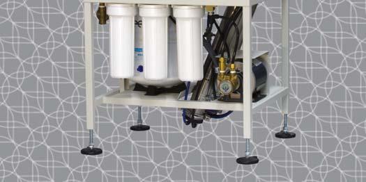
6 PRODUCT OVERVIEW Product overview DriSteem delivers this near-zero maintenance steam humidification system through the integration of two proven products, the 200 Series reverse osmosis system and the Vapormist electric humidifier, on a single skid mount. The low-maintenance humidification system produces high purity water removing over 98% of dissolved solids. This prevents chalky scale buildup from overtaking the humidifier s water tank, thereby extending intervals between humidifier maintenance by 10x or more, virtually eliminating downtime. Important: Troubleshooting information for this humidifier is located in the Vapor-logic Installation and Operation Manual shipped with your humidifier. If you do not have this manual, go to to download or order a copy. Supply water guidelines Supply water quality is an important component of humidifier reliability and maintenance. FIGURE 6-1: LOW-MAINTENANCE HUMIDIFIER Water level control Steam outlet Vapor-logic controller keypad/display Examples: Corrosive water can decrease the service life of the humidifier. Excessive water hardness can increase the humidifier maintenance requirements. To maximize humidifier service life and minimize humidifier maintenance, DriSteem has established guidelines for supply water See Table 6-1. Heating elements Table 6-1: DriSteem's lowmaintenance humidification system supply water guidelines Chlorides See Table 8-2 Tank Shroud OM-7986 Total hardness Tap water ph RO, DI, or softened water Tap water Silica Softened water only 7 to to 8.5 < 15 ppm You may wish to take action to mitigate potential negative effects to your humidifier. Supply water outside of these guidelines may void your DriSteem warranty. Please contact your DriSteem Representative or DriSteem Technical Support if you need advice. 6
. The Vapor-logic Installation and Operation Manual ships with the Lowmaintenance humidifier.")

7 PRODUCT OVERVIEW Product overview CONTROLLER The Vapor-logic controller in the Low-maintenance humidifier provides menus for all humidifier functions, with a Web interface for Ethernet access (see Figure 7-1). The Vapor-logic Installation and Operation Manual ships with the Lowmaintenance humidifier. Refer to it for information on using the keypad/display and Web interface, and for troubleshooting information. FIGURE 7-1: VAPOR-LOGIC KEYPAD/DISPLAY AND WEB INTERFACE KEYPAD/DISPLAY Static IP addresses See the Vapor-logic Controller Installation and Operation Manual shipped with the Low-- maintenance humidifier for more information about configuring IP addresses. FIGURE 7-2: WATER LEVEL CONTROL Supply water connection Room RH Set point Mode Softkeys for direct menu access Tank water level Steam output Tank status Float rod Float ball Navigation buttons for item selection System alarms System messages water levels are controlled by using a float valve and low-water cutoff switch. mc_052710_1644 OM-7396 WEB INTERFACE 7
8 SPECIFICATIONS Models, capacities, electrical specifi cations, and weights Table 8-1: Low-maintenance humidifier capacities, electrical specifications, and weights Maximum Current draw (amps) Weights Model steam capacity Single-phase Three-phase Shipping Operating kw lbs/hr kg/h 120V 208V* 240V* 277V 480V 600V 208V* 240V 277V 480V 600V lbs kg lbs kg * On 208V/240V/single-phase/three-wire and on 208V/three-phase/four-wire supplies, the neutral line provides a separate 120V circuit for the SDU fan unit. ** For wire sizing, the highest leg draw is shown due to current imbalance. Add the following to Vapormist weights if using an SDU option (these weights are for additional control components housed within the Vapormist cabinet): SDU-I: 12 lbs (5.5 kg) (SDU-I operating weight is 58 lbs [26 kg]) SDU-E: 9 lbs (4 kg) (SDU-E operating weight is 51 lbs [23 kg]) Add the following if using the SSR option: For single-phase or three-phase models drawing less than 21.7 amps, add 2 lbs (1 kg) For three-phase models drawing more than 21.7 amps, add 4 lbs (2 kg) All Vapormist models operate at 50/60 Hz. Table 8-2: Pounds of water until ADS based on supply water chloride level Supply water chloride Low-maintenance humidifier ppm Models 2-4 Models 6-8 Models Models ,500 31,700 40,600 49, ,800 15,800 20,300 24,600 20* 4,400 7,900 10,100 12, ,900 5,300 6,800 8, ,200 4,000 5,100 6, ,800 3,200 4,100 4, ,500 2,600 3,400 4, ,300 2,300 2,900 3, ,100 2,000 2,500 3, ,000 1,800 2,300 2, ,600 2,000 2, ,400 1,800 2,200 * default ADS setting To ensure <5ppm chloride enters the evaporating chamber, adjust the Automatic Drain Sequence (ADS) if needed based on supply water chloride levels. See Table 8-2 for setting recommendations. Refer to the Vapor-logic Controller Installation, Operation, and Maintenance manual for adjustment instructions. 8
9 SPECIFICATIONS Dimensions FIGURE 9-1: LOW-MAINTENANCE HUMIDIFIER DIMENSIONS AND PLUMBING CONNECTIONS Water supply line: ½" NPT (DN15) connection size 25 to 80 psi (175 to 550 kpa) required water pressure. Drain line: ¾" NPT (DN20) connection size Top view 11" (276 mm) 24.2" (614 mm) 2" (50 mm) 2.13" (54 mm) Note: Use only softened source water. Although tank maintenance is significantly enhanced with the Lowmaintenance humidifier, if hard water is used, tank maintenance will be necessary. Check humidifier tank annually for sediment buildup and float function. Left side view 16.1" (410 mm) 2.25" (57 mm) Steam outlet 1" (25 mm) Power wiring knockout Control or SDU wiring knockout Front view 18.6" (472 mm) 54.6" (1387 mm) Drain out Water inlet 12.3" (312 mm) 21.1" (536 mm) 14.5" (368 mm) 13.4" (340 mm) 2.9" (74mm) 17.6" (447 mm) 1.5" (38 mm) 24" (610 mm) Bottom view Power wiring knockout 17.13" (435 mm) 20.13" (511 mm) 0.75" (19 mm) 1" (25 mm) Control or SDU wiring knockout Drain out 24.2" (614 mm) 2.75" (70 mm) OM
10 SPECIFICATIONS Steam outlet connections Table 10-2: Steam connection sizes Low-maintenance humidification model Steam outlet 2, 4, 6, 8 1½" hose or NPT connection FIGURE 10-1: STEAM OUTLET CONNECTIONS The steam outlet is designed to connect to a steam hose or NPT connection. 10*, 12*, 14*,16* 1½" or 2" hose or NPT connection 21, 25, 30, 34 2" hose or NPT connection * If using with an SDU-E (Space Dispersion Unit External Absorption), the Low-maintenance steam outlet must be 2" to match the SDU-E steam inlet. OM-7865_aa 10
11 SPECIFICATIONS Selecting a location HUMIDIFIER When selecting a location for the humidifier, consider the following: Proximity to the duct Install the humidifier near the air duct system where the dispersion assembly will be located. The maximum recommended length for steam hose connecting a single humidifier to a dispersion assembly is 10' (3 m). The maximum recommended developed length for tubing connecting a single humidifier to a dispersion assembly is 20' (6 m). For more information about installing dispersion assemblies, see the Dispersion, document. Elevation of the installed dispersion assembly The recommended installation location for the dispersion assembly is at an elevation higher than the humidifier. However, if the dispersion assembly must be installed at an elevation lower than the humidifier, install a drip tee and drain. Before installing a dispersion assembly or interconnecting piping, review all pitch requirements in the Dispersion section of this manual. Required clearances (see Figure 12-1) Electrical connections Electrical power supply connections are at the lower or upper right rear corner of the unit. See Wiring on Pages 18 and 19. Supply water and drain piping connections Water supply piping is at the lower right front corner of the unit. Drain connection is at the lower left rear corner of the unit. See the piping illustrations and instructions starting on Page 13. Exterior wall insulation Install the humidifier on an exterior wall only if the wall is properly insulated. FIGURE 11-1: INSTALLATION OVERVIEW Electrical knockouts Flexible steam hose or tubing connects to dispersion tube(s) or to an SDU RO control cabinet Water inlet Duct Single dispersion tube with condensate return Humidifier controls and electrical area Skimmer port Drain Incoloy-sheathed immersion heaters OM-7867 DISPERSION CONTROL DEVICES See the Dispersion instructions for recommended installation locations for the dispersion assembly and associated control devices. 11
12 INSTALLATION Mounting FIGURE 12-1: LOW-MAINTENANCE HUMIDIFIER CLEARANCE RECOMMENDATIONS WARNING Mounting hazard Mount humidifier per the instructions in this manual and to a structurally stable surface. Improper mounting of the humidifier can cause it to fall or tip, resulting in severe personal injury or death. mc_060110_1540 To dispersion assembly Maintain these clearances for service and maintenance. Top (when SDU is not mounted directly above the Low-maintenance humidifier): 18"(460 mm) Right side electrical controls: 36" (915 mm) Supporting wall Left side: 12" (305 mm) OM-7868 Front 36" (915 mm) 12
13 INSTALLATION Piping: Tap/softened water FIGURE 13-1: LOW-MAINTENANCE HUMIDIFIER (TAP/SOFTENED WATER) FIELD PIPING OVERVIEW 18.7" (475 mm) Water inlet Drain out (plumbed to open drain) Water supply line: ½" NPT (DN15) connection size 25 to 80 psi (175 to 550 kpa) required water pressure. Drain line: ¾" NPT (DN20) connection size OM " (41 mm) Use only softened source water. Although tank maintenance is significantly enhanced with the Lowmaintenance humidifier, if hard water is used, tank maintenance will be necessary. Check humidifier tank annually for sediment buildup and float function. 13
14 INSTALLATION Piping: Supply water and drain piping SUPPLY WATER PIPING Use only copper for supply water piping; do not use rubber or plastic. The standard supply water connection before the fill valve is a 1/4" FIP strainer. Note: The supply water connection size is 3/8" BSP [DN10] in Europe. In cases where water hammer may be a possibility, consider installing a shock arrestor. Water pressure must be 25 to 80 psi (175 to 550 kpa). DRAIN PIPING Drain piping must be code-approved, 3/4" (DN 20) ID material rated for 212 F (100 C) minimum. The drain cup has an integral grounding plate and requires a field-installed 1" (25 mm) air gap to a drain funnel to prevent conduction of electricity in the drain line. The Low-maintenance humidification system features user-selectable drain water tempering. When drain water tempering is selected, the humidification system tempers drain water by opening the fill valve whenever the drain valve is energized, which automatically cools drain water before it enters the drain. Drain water tempering is intended to keep water entering the drain line no hotter than 140 F (60 C). Manually energizing the drain valve when the supply water is shut off can allow 212 F (100 C) water to enter the drain line. Important: Thoroughly flush supply water piping to remove pipe residue and stagnant water before connecting piping to humidifier. Pipe residue and stagnant water in water supply piping can cause foaming, preventing humidifier from reaching required steam capacity. WARNING Hot drain pipes Drain piping surface may be hot. Touching or contact with hot pipe may cause severe personal injury. FIGURE 14-1: DRAIN PIPING DETAIL 1" (25 mm) air gap Open drain Hose clamp* Drain hose* Pitch 1/8"/ft (1%) toward drain 3/4" (DN20) I.D. To drain * Ship with humidifier, and can be ordered from DriSteem. 14
15 INSTALLATION Piping: Supply water and drain piping Observe the following precautions when selecting and installing drain piping to ensure personal safety and material integrity: When using copper or other metallic drain piping, ground the drain piping to the earth ground lug in the humidification system. Chlorinated polyvinyl chloride (CPVC) piping is a non-metallic alternative for drain piping. It is rated up to 212 F (100 C) for intermittent-use, lowpressure applications. The connection size for the steam cylinder drain is 1" (DN25) hose. Do not reduce this connection size. If drainage by gravity is not possible, use a reservoir pump rated for 212 F (100 C) water. A drain hose is provided to function as the flexible connection from the drain cup to the field-installed open drain. See Figure AUTOMATIC DRAIN WATER TEMPERING The Low-maintenance humidification systems are shipped with drain water tempering set to OFF. To activate automatic drain water tempering see the Vapor-logic Installation and Operating Manual. 15
16 INSTALLATION Piping: Schematics FIGURE 16-1: PIPING SCHEMATIC LMH-piping-1 16
17 INSTALLATION Piping: Schematics FIGURE 17-1: PIPING SCHEMATIC LMH-piping-1a 17
18 INSTALLATION Wiring HUMIDIFIER FIELD WIRING All wiring must be in accordance with all governing codes, and with the humidifier wiring diagrams. The diagrams are located inside the removable humidifier controls and electrical area and the RO control cabinet on the right side of the humidifier cabinet. Power supply wiring must be rated for 220 F (105 C). When selecting a location for installing the humidifier, avoid areas close to sources of electromagnetic emissions such as power distribution transformers. The fill valve, drain valve, probes, and temperature sensors use Class 2, 24 VAC power. The use of semiconductor fusing sized per the National Electric Code is recommended with the SSR option. GROUNDING REQUIREMENTS The approved earth ground must be made with solid metal-to-metal connections and must be a good conductor of radio frequency interference (RFI) to earth (multistranded conductors). Ground wire should be the same AWG (mm 2 ) size as the power wiring or sized per NEC requirements (in Europe, IEC requirements). PROPER WIRING TO PREVENT ELECTRICAL NOISE Electrical noise can produce undesirable effects on electronic control circuits, which affects controllability. Electrical noise is generated by electrical equipment such as inductive loads, electric motors, solenoid coils, welding machinery, or fluorescent light circuits. The electrical noise or interference generated from these sources (and the effect on controllers) is difficult to define, but the most common symptoms are erratic control or intermittent operational problems. Important: For maximum EMC (electromagnetic compatibility) effectiveness, wire all humidity, high limit, and airflow controls using multicolored shielded/ screened plenum-rated cable with a drain wire for the shield/screen. Connect the drain wire to the shield/screen ground terminal with wire less than 2" (50 mm) in length. Do not ground shield at the device end. mc_061610_0625-na WARNING Electric shock hazard Only qualified electrical personnel should perform field wiring installation procedures. Improper wiring or contact with energized circuits can cause property damage, severe personal injury, or death as a result of electric shock and/or fire. Do not remove the humidifier electrical panel cover or the heater terminal cover until electrical power is disconnected. Contact with energized circuits can cause property damage, severe personal injury, or death as a result of electrical shock. mc_062310_0629 FIGURE 18-1: FIELD WIRING REQUIREMENTS Fused disconnect (provided by installer) Low-maintenance humidifier Power supply (provided by installer) OM-1007_LMH Notes: Control wiring and power wiring must be run in dedicated or separate earthed metal conduit, cable trays, or trunking. Separate the line voltage wiring from low voltage control circuit wiring when routing electrical wiring inside the humidifier cabinet. Do not use chassis or safety grounds as current-carrying commons. Never use a safety ground as a conductor or neutral to return circuit current. mc_062310_0630-vmht 18
19 INSTALLATION Wiring FIGURE 19-1: SHIELDED/SCREENED CABLE DRAIN WIRE CONNECTION TO LUG Humidifier side view Vapor-logic keypad/display Microprocessor board (See the Vapor-logic manual for control wiring) Shield/screen ground lug OM-7869 Note: For maximum EMC effectiveness, all humidity, temperature, and airflow controls should be wired using multicolored shielded/screened plenum-rated cable with a drain wire for the shield/screen. The drain wire should be connected to the shield/screen ground terminal with its length kept to less than 2" (50 mm). 19
20 INSTALLATION Sensor placement SENSOR LOCATION IS CRITICAL Sensor location has a significant impact on humidifier performance. See the recommendations below and Figure Note: DriSteem recommends that you do not interchange room and duct humidity devices. Room humidity devices are calibrated with zero or little airflow, whereas duct humidity devices require air passing across them. Recommended humidity control (transmitter/humidistat) locations: A. Ideal. Ensures the best uniform mix of dry and moist air with stable temperature control. B. Acceptable, but room environment can affect controllability, such as when sensor is too close to air grilles, registers, or heat radiation from room lighting. C. Acceptable. Provides uniform mixture of dry and moist air. If extended time lag exists between humidity generation and sensing, extend sampling time. D. Acceptable (behind wall or partition) for sampling entire room if sensor is near an air exhaust return outlet. Typical placement for sampling a critical area. E. Not acceptable. These locations might not represent actual overall conditions in the space. F. Not acceptable. Do not place sensors near windows, door passageways, or areas of stagnant airflow. Other factors affecting humidity control Humidity control involves more than the controller s ability to control the system. Other factors that play an important role in overall system control are: Size of humidification system relative to load Overall system dynamics associated with moisture migration time lags Accuracy of humidistats and humidity transmitters and their location Dry bulb temperature accuracy in space or duct Velocities and airflow patterns in ducts and space environments Electrical noise or interference mc_072011_1656 Recommended safety (airflow and high limit) sensor location: G. Best sensing location for high limit humidistat or humidity sensor and airfl ow proving switch. 20
21 INSTALLATION Sensor placement FIGURE 21-1: RECOMMENDED SENSOR LOCATIONS Outside air Damper control Relief air Return air Air handling C unit 8' to 12' (2.4 m to 3.7 m) min. G High limit humidistat or high limit transmitter (set at 90% RH maximum) for VAV applications Airflow switch or differential pressure switch (sail type recommended for VAV applications) A Window E Wall or partition D B E Vapor absorption has taken place Point of vapor absorption Humidifier dispersion assembly Turning vanes DC-1084 mc_060508_0750 F Doorway E F Window Temperature compensation option: Place a temperature compensation sensor on the lower corner of the inside surface of double-pane window glass on north- or northeast-facing window. 21
22 OPERATION Principle of operation FIGURE 22-1: LOW-MAINTENANCE HUMIDIFIER COMPONENTS RO water inlet Tank overflow Steam outlet Heating element CAUTION To prevent concentrate from precipitating and causing irreversible fouling of the RO membrane, do not operate the system with the concentrate to drain control valve completely closed. Drain valve Temperature Sensor OM-7865_LMH 22

23 OPERATION Principle of operation The Low-maintenance humidifier produces water that has been treated using reverse osmosis and does not require skimming. 1. When the system is first activated, the RO system activates and the evaporating chamber fills with RO water to the operating level. 2. On a call for humidity, the heating elements are energized, causing the water to boil. The float valve opens and closes as needed to maintain the operating water level. 3. Steam created in the evaporating chamber flows through vapor hose or piping to the dispersion assembly, where it is discharged into the airstream. FIGURE 23-1: CONTROL VALVES SHUTDOWN 1. Put the system in 'Standby' mode or remove power. Close the isolation valve if it is installed on the feed line. 2. If the unit is to be shut down for more than one week, an automatic system flush will occur every 168 hours (adjustable) to prevent bacterial growth. 3. When the system is restarted after an extended shutdown, follow initial system start-up procedures. 23
24 OPERATION Start-up checklist The following checklist is to be completed one at a time, from top to bottom, in order to ensure proper installation. If an item in the Start-up checklist below does not apply to your system, skip to the next item and continue the process. Read this manual and all other information that was provided with your system. Verify that all field wiring is done according to the instructions in this manual and in the unit wiring diagram. Confirm that proper grounding and an approved earth ground are provided. Confirm that the input signal is consistent with the Vapor-logic controller's expected input signal. Input signals are listed in the Vapor-logic Setup menu. See Installation Step 2: Setup in the Vapor-logic Installation and Operation Manual. Make sure valve on manifold that supplies the pressure tank is closed. Verify precharge on pressurized RO storage tank is between 26 and 28 psi (179 and 194 kpa). Do not precharge over 28 psi (194 kpa). Note: This precharge pressure is to maximize download volume for integrated pressurized RO storage tank cut-in and cut-out switch points at 30 and 50 psi (27 and 345 kpa) respectively. Check to make sure the wiring diagrams and other items shipped in control cabinet(s) have been removed and stored in a safe location. Open concentrate and recirculation control valves slightly (about ½ counterclockwise rotation). Inspect to insure that no flexible plumbing lines have been kinked or damaged during installation. Turn on supply water and confirm that there are no leaks. Turn on power to the unit, and confirm the Main menu is displayed on the keypad/display. The display may take several seconds to appear as the controller powers up. 24
25 OPERATION Start-up checklist Change/confirm mode in the Vapor-logic controller in the Main Menu to Auto and that status is Filling. (Main > Status > Mode > Auto > Home) Note: A non-audible low inlet pressure alarm indicator will need to be manually cleared on the Vapor-logic controller. To clear a fill alarm, press the flashing alarm button, select "Clear". Repeat until all fill alarms are clear. If fill alarms continue, confirm the water inlet valve is open. Contact DriSteem Technical Support at if problem continues. The process can take about 15 minutes to complete. When Filling appears in main menu, confirm that the system inlet pressure is at least 40 psi (276 kpa) on the display and that the humidifier tank is filling with water. Make sure the tank has filled with water. See the Damage from dry startup Caution on Page 26. With sufficient water in the tank, airflow switch closed, high limit switch closed, and the humidifier getting a call for humidity, verify the heater outputs are activated. This is indicated by the mode change from "Auto Filling" to " Auto Heating". Check the amp draw of the heaters. Refer to the humidifier wiring diagram for the proper rating. With sufficient water available, the system in Auto mode, and the storage tank pressure is between 26 and 28 psi (179 and 195 kpa), verify that the pump is activated and the heater outputs are activated. In the Status screen, confirm that the high limit humidistat input is closed or the high limit transmitter is connected. Set permeate flow and recirculate flow meter to desired setting. (See Table 28-1). In the Status screen, confirm that the Duct Airflow Switch is closed. If you experience difficulties, have the keypad/display information available along with the serial number and unit Model, and call DriSteem Technical Support at
26 OPERATION Start-up procedure After the system is installed and connected properly: 1. Verify that the humidifier, controls, piping, electrical connections, steam supply, and dispersion units(s) are installed according to the following: Installation instructions in this manual Vapor-logic Installation and Operation Manual (shipped with unit) Installation section Pre-installation checklist Ladder style wiring diagram (inside humidifier electrical panel cover) External connections wiring diagram (inside control cabinets). Remove from humidification system before start-up. All governing codes 2. Verify that all electrical connections are secure before applying power. 3. Make sure all electrical covers are in place and secure. See Warning at right. 4. Verify that the humidifier is mounted level. See operating weights in Table Verify that the humidifier is level front to back and side to side after it is full of water. 6. Read the Operation section of the Vapor-logic Installation and Operation Manual. Note: During start-up, do not leave the humidifier unattended. 7. Perform all applicable Start-up checklist items. See Page Monitor humidifier operation through multiple fill cycles. The humidifier operating status appears on the keypad/display. The Vapor-logic In stal la tion and Op er a tion Man u al is a comprehensive operation manual. Refer to it for information regarding the following features: Keypad/display setup and menu information Control input signals and functions Drain, flush, and skim features Safety features Alarm screens and fault messages The manual was shipped with your humidifier and is available at our Web site: mc_052410_1340 WARNING Electric shock hazard Only qualified electrical personnel should perform start-up procedure. Contact with energized circuits can cause property damage, severe personal injury or death as a result of electrical shock or fire. Make sure that all electrical covers are in place and secure before turning on electrical power. These include the heater terminal cover, electrical panel cover, and subpanel access panels. CAUTION Damage from dry startup In the event the humidifier tank does not contain water and the heaters are energized, turn main power off. Operation of the heaters without water will cause damage to the humidifier. Before turning main power on, verify that all wiring has been completed per the wiring instructions in this manual and the unit wiring diagrams. mc_052410_
. 4. Run the system as much as possible, on a continuous basis. 5. Confirm chlorine level in permeate water to assure there is no pass through.")
27 OPERATION Start-up procedure OPERATING DO'S AND DONT'S DO 1. Change the cartridge filters regularly. 2. Monitor the system and keep a log daily. 3. Adjust the system to the recommended value. (See Table 28-1). 4. Run the system as much as possible, on a continuous basis. 5. Confirm chlorine level in permeate water to assure there is no pass through. Once detected, change the carbon filter based on timing determined. DON T 1. Permit chlorine in the feed water. 2. Shut down the system. If the system is shut down for more than one month, the system must be treated with a membrane preservation. 3. Close the condensate valve completely. 4. Operate the system with insufficient feed flow. 5. Modify or cut the humidifier tank and frame drain hoses (see Figure 27-1) as this can decrease the performance and/or cause damage to the Low-maintenance humidifier. Important If the system is not in operation within six months of shipment, it is strongly recommended to use an organic cleaning cartridge prior to performing the start-up checklist to ensure proper operation. See page 44 for information and part number. CAUTION Do not operate the system with the control valve closed. Important: By setting the feed pressure as low as possible to meet the application requirement, the service life of the pump and RO elements will be optimized. The system should be run continuously when possible, rather than go through frequent start/stop cycles. CAUTION Damage to pump Do not close the valve. Do not operate the pump below minimum combined flow rate (permeate + concentrate + recirculating). FIGURE 27-1: DRAIN HOSE Drain hoses 27
28 OPERATION Start-up procedure Table 28-1: Low-maintenance humidification RO station specifications Rated capacity, permeate Model Low-maintenance humidifier Models membrane Low-maintenance humidifier Models membranes Gallons/minute Concentrate flow (reject) Gallons/minute Recirc (adjustable as needed) Gallons/minute System pressure, psi F ( C) 10/50 10/50 Pre-filters Sediment cartridge - 5 micron 1 1 Carbon cartridge - 10 micron 2 2 Pressure switch settings Low pressure (for pump protection) 8 psi 8 psi Notes: Adjusting the recirc and concentrate flow rates is a balancing act that affects overall system efficiency. While holding permeate (RO-treated water) flow constant, the following adjustments and corresponding results can be expected: Increasing concentrate flow & decreasing recirculation flow Maintains system pressure Increases drain/waste/concentrate water flow rate Promotes membrane life Decreasing concentrate flow & increasing recirculation flow Maintains system pressure Reduces drain/waste/concentrate water flow rate Decreases expected membrane life The flow rates of your system can be adjusted to better fit your needs but DriSteem recommends targeting the flow rates listed in Table
29 MAINTENANCE Maintenance information Low-maintenance humidifiers produce and use RO water. Because RO water is nearly mineral free, cleaning the evaporating chamber should not be necessary (See Figure 41-1). However, there are some maintenance steps that should be followed to ensure all parts of the unit are in working order. Important: Verify regularly that water processing equipment is operating correctly. The presence of chlorides in water will eventually cause pitting and failure of the humidifier tank and its components. Damage caused by chloride corrosion is not covered by your DriSteem warranty. The Low-maintenance humidifier has an automatic drain sequence (ADS) set based on default supply concentration of 20 ppm. Adjust ADS to actual supply water chloride concentration. COOL DOWN HUMIDIFIER If the tank is hot, cool it down by using the Vapor-logic controller to open the drain valve. The float valve will open allowing cool water to run into the tank until it is cool enough to handle. Then shut off the water supply, and allow the tank to drain completely. WARNING Electric shock hazard Do not remove humidifier electrical panel cover, heater terminal cover, or subpanel access panels until electrical power is disconnected. Improper wiring or contact with energized circuits can cause property damage, severe personal injury, or death as a result of electric shock and/or fire. Only qualified electrical personnel should perform maintenance procedures. mc_060310_
30 MAINTENANCE Maintenance information INSPECTION AND MAINTENANCE 1. Remove the evaporating chamber: If the tank is hot, follow the instructions in Cool down humidifier above before proceeding. Remove the two fasteners on each side of the cover enclosure. Remove the enclosure. See Electric shock hazard Warning. Note: If the humidifier has an SDU mounted directly above it, remove the SDU cover before removing the humidifier cover. Shut off the water supply. Using the Vapor-logic controller, allow the tank to drain completely. Shut off the electrical supply. Disconnect the fill line at the fill fitting. Disconnect the electrical plugs between the tank components and the back of the electrical panel (includes: power plug, low water switch plug, tank temperature sensor plug and thermal trip plug). Important: Disconnect by pulling on plug housing. Do not disconnect by pulling on cord or wires. Disconnect the drain union on the back left corner of the frame. Disconnect the steam supply hose from the top of the tank. Lift the tank foot above the frame flange and slide the tank assembly forward to remove. WARNING Hot surface and hot water hazard Do not touch the tank or drain piping until the unit has had sufficient time to cool, or serious injury can occur. Opening the drain valve when the tank is hot can discharge water with a temperature up to 212 F (100 C) into the plumbing system. This can cause damage to the plumbing system if the humidifier is not properly connected to a water tempering device such as a DriSteem Drane-kooler device. mc_060110_1640 WARNING Electric shock hazard Contact with energized circuits can cause severe personal injury or death as a result of electric shock. To prevent shock, disconnect electrical power before performing service or maintenance procedures on an part of the humidification system. When performing maintenance on the humidifier: Always switch the keypad control mode to Standby. Place all power disconnects in OFF position and lock in OFF position. Close the field-installed manual supply water shut-off valve. mc_031110_
31 MAINTENANCE Maintenance information 2. Loosen the four cover bolts and remove the cover assembly from the tank. 3. Inspect the tank interior for debris or pitting. 4. Inspect the valve inlet for debris. 5. Check the operation of the float valve and the condition of the float seat. 6. Check the low water switch to make sure the float slides freely on the stem. 7. Secure the chamber cover making sure the cover gasket is seated and the chamber is sealed. 8. Reinstall the evaporating chamber. Reconnect the fill line. Reconnect electrical plugs (the plugs are color coded). Reconnect drain union. Reconnect steam hose. 9. Verify electrical connections: Verify that all DIN rail-mounted components are securely fastened to DIN rail. Verify that all power terminal screws and lugs are tight from power block to heaters. Verify that all plugs under the humidifier cover are completely plugged in. 10. Close the drain valve. 11. Turn on the water supply. 12. Turn on the electrical power. OFF-SEASON SHUT-DOWN PROCEDURE Do not shut-off the Low-maintenance humidifier during off-season. To prevent stagnant water or bacterial growth, the Low-maintenance humidifier will flush the system once weekly if there is no call for humidity. 31

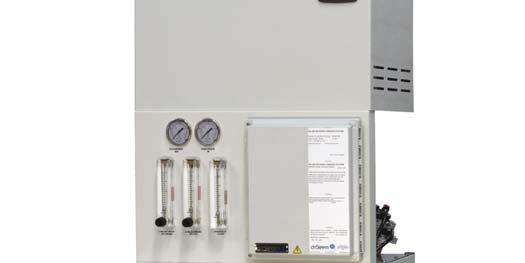
32 MAINTENANCE Maintenance information MAINTENANCE TIPS Maintain proper operating conditions: Do not exceed 90 psi (620 kpa)on the filter inlet pressure reading. Do not over use recirculation valve flow. This can cause premature scaling of the membrane. A proper concentrate flow is required for a long membrane life. See page 28 for maximum recirculation valve flow. To ensure no chlorine reaches the RO membranes, test the water from your dechlorinator periodically for chlorine break through. FIGURE 32-1: SEDIMENT FILTER WHEN TO CHANGE SEDIMENT AND CARBON FILTERS Sediment and carbon filters should be changed regularly to maintain proper pressure and flow and water quality. Change the carbon filter when chlorine from supply water starts to pass through. The carbon filter removes chlorine. Check regularly for chlorine pass through. To check for chlorine, obtain a water sample from the concentrate drain line and test the water. If chlorine is present, change the carbon filter and record the interval to estimate the next carbon filter change. Change the sediment filter when the difference between filter inlet pressure and filter outlet pressure increases by 10 psi over the initial pressure difference. For example, if initial readings are 60 psi in and 58 psi out, the difference is 2 psi. Therefore, when that difference reaches 12 psi, it is time to replace the sediment and carbon cartridges. DriSteem replacement part 2.5" x 10" - (part number: ) FIGURE 32-2: CARBON FILTER CHANGING CARTRIDGE FILTERS 1. Put the system into 'Standby' mode and shut down the Low-maintenance humidifier. 2. Close inlet supply valve. 3. Un-assemble the filter housing (twist the sump counter-clockwise). 4. Remove and inspect the cartridge. Replace as needed. 5. Before replacing housing, insure that O-ring seal is lubed and placed in groove of housing. Inspect seal and replace as needed. 6. Assemble housing (turn the sump clockwise into the cap until tight). DriSteem replacement part 2.5" x 10" - (part number: ) CAUTION Chlorine can damage the membrane. A carbon pre-filter is installed to remove chlorine from fee water. Care must be taken to change this carbon filter as needed to accomplish effective chlorine removal. Excessive chlorine in feed stream may require additional pre-filtration. The feed stream should be tested for chlorine at least once a week. Always follow proper maintenance procedures. 32

33 MAINTENANCE Maintenance continued WHEN TO CLEAN OR REPLACE MEMBRANES In normal operation, the membrane in reverse osmosis elements can become fouled by mineral scale, biological matter, and grime. These deposits build up during operation until it causes loss in water output or loss of salt rejection, or both. Elements should be cleaned or replaced whenever the water output rate drops by 10 percent from its initial flow rate (the flow rate established during the first 24 to 48 hours of operation) or when TDS in the product water (permeate) rises above 50. This is indicated through a message on the Vaporlogic controller (above 75 will alarm). It should be noted that the water output rate will drop if feed water temperature decreases (about 1.5% per F). This is normal and does not indicate membrane fouling. A malfunction in the pretreatment, pressure control or pump can cause a drop in feed water delivery pressure, feed water flow, product water output, or an increase in salt passage. If such adjustments are needed, the element may not require cleaning. FIGURE 33-1: PRE-FILTER Carbon filter: Primarily to remove chlorine; also removes organics and sediments down to 10 microns. 2. Sediment filters: Removes sediments and particles down to 5 micron size. 33


34 MAINTENANCE Maintenance continued REPLACING MEMBRANES TOOLS Rubber mallet Flat blade screwdriver Open end wrench, ⅞ inch Food grade RT-111 silicone Safety glasses FIGURE 34-1: USE WRENCH AND RATCHET TO REMOVE CLAMP PROCEDURE 1. Turn OFF the Low-maintenance humidifier system. 2. Relieve pressure on the membrane by opening the supply valve. 3. Remove all lines from the top of the pressure vessel(s). Make sure the fittings are marked so the fittings go back to the correct locations after replacing. Note: Membranes on the Low-maintenance humidification system are removed and inserted from the top. FIGURE 34-2: REMOVE MEMBRANE TUBE CAP 4. Remove u-pins from the vessel. Slowly and carefully pull the end plugs out from the fitting with a channel lock. See Figure Remove end plugs by pulling carefully. See Figure FIGURE 34-3: REMOVE MEMBRANE 34
35 MAINTENANCE Maintenance continued MEMBRANE CLEANING IN THE LOW-MAINTENANCE HUMIDIFIER Membrane cleaning cartridges: Clean membranes without having to remove them from the Lowmaintenance humidifier Reduce downtime Maintain the system performance at a higher level Prolong membrane life by regular use of cleaning cartridges FIGURE 35-1: 10 INCH SCALE CLEANING CARTRIDGE HOW DOES IT WORK? NOTE: Clean monthly to obtain optimum results. 1. Exchange the system's sediment filter with a cleaning cartridge. 2. Follow the instructions. 3. Restart the system. 4. Repeat the process if required. SCALE CLEANING CARTRIDGE DriSteem replacement part 2.5" x 10" - (part number: ) The scale cleaning cartridge is for removal of mineral scale and build-up. CLEANING PROCEDURE 1. Put the system into 'Standby' mode and shutdown the Low-maintenance humidifier. 2. Disconnect permeate line and divert to drain before any cleaning cartridge is installed. CAUTION Handle all chemicals with care. Wear protective clothing and eye protection. 3. Remove the sediment filter from the pre-filter housing. 4. Replace the sediment filter with the cleaning cartridge and assemble into the filter housing. 5. Turn the system ON and put into 'Auto' mode. After seconds, shut down the system. OPTIONAL: Instead of time, use one of the following criteria: a. Run the system until the ph of the concentrate is almost the same as the cleaning solution (ph=3) b. Permeate rate for the system drops to a very low value. CAUTION The system must be flushed thoroughly between acid and alkaline cleaning. 6. Let the membrane(s) soak in the cleaning solution overnight. 7. Remove the empty cleaning cartridge and replace it with the original filter. 8. Restart the system. Direct the permeate to drain for five minutes. 9. Go back to normal operations. 35
36 MAINTENANCE Maintenance continued ORGANIC CLEANING CARTRIDGE The organic cleaning cartridge is for removal of organics/fouling. FIGURE 36-1: 10 INCH ORGANIC CLEANING CARTRIDGE CLEANING PROCEDURE 1. Put the system into 'Standby' mode and shutdown the Low-maintenance humidifier. 2. Disconnect permeate line and divert permeate to drain during cleaning. 3. Remove the sediment filter from the filter housing. 4. Replace the sediment filter with the cleaning cartridge and assemble into the filter housing. 5. Turn the system ON. After seconds, shut down the Lowmaintenance humidifier. OPTIONAL: Instead of time, use one of the following criteria: a. Run the system until the ph of the concentrate is almost the same as the cleaning solution (ph=10-12) b. Permeate rate for the system drops to a very low value. DriSteem replacement part 2.5" x 10" - (part number: ) 6. Let the membrane(s) soak in the cleaning solution overnight. 7. Remove the empty cleaning cartridge and replace it with the original filter. 8. Restart the system. Direct the permeate to drain for five minutes. 9. Go back to normal operations. CAUTION Handle all chemicals with care. Wear protective clothing and eye protection. CAUTION The system must be flushed thoroughly between acid and alkaline cleanings. 36
READ AND SAVE THESE INSTRUCTIONS VAPORMIST. Electric-to-Steam Humidifier. Installation, Operation, and Maintenance Manual
 READ AND SAVE THESE INSTRUCTIONS VAPORMIST Electric-to-Steam Humidifier Installation, Operation, and Maintenance Manual WARNINGS AND CAUTIONS Warnings and cautions WARNING Indicates a hazardous situation
READ AND SAVE THESE INSTRUCTIONS XT SERIES. Electrode Steam Humidifiers. Installation, Operation, and Maintenance Manual
 READ AND SAVE THESE INSTRUCTIONS XT SERIES Electrode Steam Humidifiers Installation, Operation, and Maintenance Manual Warnings and cautions WARNINGS AND CAUTIONS WARNING Indicates a hazardous situation
READ AND SAVE THESE INSTRUCTIONS XTR. Electrode Steam Humidifier. Installation, Operation, and Maintenance Manual
 READ AND SAVE THESE INSTRUCTIONS XTR Electrode Steam Humidifier Installation, Operation, and Maintenance Manual Warnings and cautions WARNINGS AND CAUTIONS WARNING Indicates a hazardous situation that
CRUV. Electric Humidifier. Installation, Operation, and Maintenance Manual
 CRUV Electric Humidifier Installation, Operation, and Maintenance Manual ATTENTION INSTALLER Read this manual before installing. Leave manual with product owner. DRI-STEEM technical support 800-328-4447
Vapormist Electric Humidifier. Installation, Operation and Maintenance Manual
 Vapormist Electric Humidifier Installation, Operation and Maintenance Manual ATTENTION INSTALLER Read this manual before installing. Leave manual with product owner. DRI-STEEM technical support 800-328-4447
READ AND SAVE THESE INSTRUCTIONS HUMIDI-TECH. Electric Humidifier. Installation, Operation, and Maintenance Manual
 READ AND SAVE THESE INSTRUCTIONS HUMIDI-TECH Electric Humidifier Installation, Operation, and Maintenance Manual WARNINGS AND CAUTIONS Warnings and cautions WARNING Indicates a hazardous situation that
Vaporstream Electric Humidifier. Installation, Operation, and Maintenance Manual
 Vaporstream Electric Humidifier Installation, Operation, and Maintenance Manual Warnings and cautions WARNING Indicates a hazardous situation that could result in death or serious injury if instructions
Vaporstream Electric Humidifier. Installation, Operation and Maintenance Manual
 Vaporstream Electric Humidifier Installation, Operation and Maintenance Manual ATTENTION INSTALLER Read this manual before installing. Leave manual with product owner. DRI-STEEM technical support 800-328-4447
XT SERIES. Electrode Steam Humidifiers. Easy to maintain Adaptable Comprehensive control with Vapor-logic option
 XT SERIES Electrode Steam Humidifiers Easy to maintain Adaptable Comprehensive control with Vapor-logic option Cost-effective steam humidification XT Series electrode steam humidifiers from DriSteem provide
STS Steam-to-Steam Humidifier
 IMPORTANT: Read and save these instructions. STS Steam-to-Steam Humidifier Installation, Operation, and Maintenance Manual Warnings and cautions WARNING Indicates a hazardous situation that could result
READ AND SAVE THESE INSTRUCTIONS STS. Steam-to-Steam Humidifier. Installation, Operation, and Maintenance Manual
 READ AND SAVE THESE INSTRUCTIONS STS Steam-to-Steam Humidifier Installation, Operation, and Maintenance Manual WARNINGS AND CAUTIONS Warnings and cautions WARNING Indicates a hazardous situation that could
VAPORSTREAM. Electric-to-Steam Humidifier. With Vapor-logic controller Web-enabled access Interoperability via Modbus or optional BACnet or LonTalk
 VAPORSTREAM Electric-to-Steam Humidifier With Vapor-logic controller Web-enabled access Interoperability via Modbus or optional BACnet or LonTalk High-performance humidification APPLICATION VERSATILITY
XTR Electrode Steam Humidifier. Installation, Operation, and Maintenance Manual
 XTR Electrode Steam Humidifier Installation, Operation, and Maintenance Manual Safety precautions ATTENTION INSTALLER Read this manual before installing humidifier. Leave manual with product owner. DRI-STEEM
XT Series Electrode Steam Humidifier. Installation, Operation, and Maintenance Manual
 XT Series Electrode Steam Humidifier Installation, Operation, and Maintenance Manual ATTENTION INSTALLER Read this manual before installing humidifier. Leave manual with product owner. DRI-STEEM technical
GTS. Installation, Operation, and Maintenance Manual WARNING. Gas-to-Steam Humidifier
 READ AND SAVE THESE INSTRUCTIONS GTS Gas-to-Steam Humidifier Installation, Operation, and Maintenance Manual WARNING Fire or explosion hazard If the information in this manual is not followed exactly,
XT SERIES. Electrode Steam Humidifiers. Easy to maintain Adaptable Comprehensive control with Vapor-logic option
 XT SERIES Electrode Steam Humidifiers Easy to maintain Adaptable Comprehensive control with Vapor-logic option Cost-effective steam humidification Model XTP XT Series electrode steam humidifiers from DriSteem
Steam Humidifier Models 1150 and 1160
 Humidifier Steam Humidifier Models 1150 and 1160 Installation, Operation, and Maintenance Manual READ AND SAVE THESE INSTRUCTIONS TABLE OF CONTENTS PRODUCT OVERVIEW.............................. 3 Materials
THE SIX STEPS OF HUMIDIFICATION DESIGN
 THE SIX STEPS OF HUMIDIFICATION DESIGN To help you better understand the humidification process, this issue of Engineering Humidification will walk you through the basic steps of humidification system
Humidifi er FAQ. Why is the humidifier not running? The following conditions need to be satisfied before the humidifier sequence can start:
 Humidifi er FAQ UNIT OPERATION AND TROUBLESHOOTING Why is the humidifier not running? The following conditions need to be satisfied before the humidifier sequence can start: Must be in Auto mode No flashing
VT Series. Service Kit Manual CAUTION
 VT Series Electric Humidifier Service Kit Manual WARNING Indicates a hazardous situation that could result in death or serious injury if instructions are not followed. CAUTION Indicates a hazardous situation
GTS Gas-to-Steam Humidifier
 IMPORTANT: Read and save these instructions. GTS Gas-to-Steam Humidifier Installation, Operation, and Maintenance Manual WARNING! If the information in this manual is not followed exactly, a fire or explosion
LTS Liquid-to-Steam Humidifier. Installation, Operation and Maintenance Manual
 LTS Liquid-to-Steam Humidifier Installation, Operation and Maintenance Manual Overview LTS models....3 Dimensions....4 Output capacities....6 Weights, connections and heated water properties.... 7 Installation
Ultra-sorb Models LV and LH
 Ultra-sorb Models LV and LH Steam Dispersion Panels Installation, Operation, and Maintenance Manual For applications using steam from a boiler or from any DRI-STEEM steam generating humidifier. Overview
Residential Steam Humidifier
 Residential Steam Humidifier Model HUMXXSTM3034 Residential Steam Humidifier Owner s Manual Includes Safety & Operating Instructions READ AND SAVE THESE INSTRUCTIONS TABLE OF CONTENTS Safety... 2 Introduction...
"ER" Series Electric Humidifier
 ER-1 Standard Water "ER" Series Electric Humidifier The Electric Humidifier from PURE Humidifier Co. is loaded with features and options. All you need is tap water, electricity, and a sanitary drain the
VAPORSTREAM. Electric-to-Steam Humidifier. With Vapor-logic controller Web-enabled access I nteroperability via Modbus or optional BACnet or LonTalk
 VAPORSTREAM Electric-to-Steam Humidifier With Vapor-logic controller Web-enabled access I nteroperability via Modbus or optional BACnet or LonTalk High-performance humidification dristeem offers a complete
Vapor-logic3 Humidifier Control System
 Vapor-logic3 Humidifier Control System Installation and Operation Manual from the Humidification Experts Table of contents Overview Product overview...1 Summary of features...2 Control input signals...3
Vapor-logic 3 to Vapor-logic4
 Vapor-logic 3 to Vapor-logic4 Adaptor Board Installation Manual Warnings and c autions Warnings and cautions WARNING Indicates a hazardous situation that could result in death or serious injury if instructions
DRI-STEEM CRU SERIES ELECTRIC STEAM HUMIDIFIERS
 READ AND SAVE THESE INSTRUCTIONS DRI-STEEM CRU SERIES ELECTRIC STEAM HUMIDIFIERS Installation Instructions and Maintenance Operations Manual For Toll-Free Customer Support, Call: 1-800-328-4447 UL RECOGNIZED
ES Series Electric Humidifier
 Read and Save These Instructions Standard Water ES Series Electric Humidifier Installation Instructions Operation and Maintenance Manual ETL LISTED HUMIDIFIER Our results are comforting Form No: ESOM-08-08
XTR Electrode Steam Humidifier. Installation, Operation, and Maintenance Manual
 XTR Electrode Steam Humidifier Installation, Operation, and Maintenance Manual ATTENTION INSTALLER Read this manual before installing humidifier. Leave manual with product owner. DRI-STEEM technical support
EVAPORATIVE COOLING AND HUMIDIFICATION. High-Pressure System Wetted Media System
 EVAPORATIVE COOLING AND HUMIDIFICATION High-Pressure System Wetted Media System Energy efficient Provides both direct and indirect evaporative cooling Multiple zone capabilities in air handlers, ducts,
Steam Humidification Light Commercial Applications. Better technology means better business.
 Steam Humidification Light Commercial Applications Better technology means better business. Aprilaire Steam Humidifiers are built to last. Through extensive research and over 50 years expertise in humidification
Steam Injection Humidifiers for use with steam boilers. Installation, Operation, and Maintenance Manual
 Steam Injection Humidifiers for use with steam boilers Installation, Operation, and Maintenance Manual ATTENTION INSTALLER Read this manual before installing. Leave manual with product owner. Where to
L A signature series TA T N E RE O, A L L A T S IN
 signature series COMMERCIAL STEAM GENERATORS INSTALLATION, OPERATION AND MAINTENANCE MANUAL INSTALLATION MANUAL COMMERCIAL STEAM GENERATOR SIGNATURE SERIES (SS) INTRODUCTION Steam Sauna manufactures steam
HIGH-PRESSURE ATOMIZING SYSTEM. Humidification and adiabatic cooling. Energy efficient Reduces cooling load Multiple zone capabilities
 HIGH-PRESSURE ATOMIZING SYSTEM Humidification and adiabatic cooling Energy efficient Reduces cooling load Multiple zone capabilities Preliminary 02071 Advanced, efficient humidification PURE PRESSURIZED
GTS. User Manual. Gas-to-Steam Humidifier. Affix product label here.
 Following installation of this steam-generating humidifier, the installer shall instruct the user in the operation of the steam-generating humidifier and the safety devices. The installer shall give at
EVAPORATIVE COOLING AND HUMIDIFICATION. High-Pressure System Wetted Media System
 EVAPORATIVE COOLING AND HUMIDIFICATION High-Pressure System Wetted Media System Energy efficient Provides both direct and indirect evaporative cooling Multiple zone capabilities in air handlers, ducts,
GTS Gas-to-Steam Humidifier
 IMPORTANT: Read and save these instructions. GTS Gas-to-Steam Humidifier Installation, Operation, and Maintenance Manual WARNING! If the information in this manual is not followed exactly, a fire or explosion
ULTRA-SORB. Installation, Operation, and Maintenance Manual MODEL. Steam Dispersion Panel. For pressurized steam applications
 READ AND SAVE THESE INSTRUCTIONS ULTRA-SORB MODEL XV Steam Dispersion Panel Installation, Operation, and Maintenance Manual For pressurized steam applications Table of contents MECHANICAL SPECIFICATIONS..................................................1
Vapor-logic3 Humidifier Control System. Installation and Operation Manual
 Vapor-logic3 Humidifier Control System Installation and Operation Manual Table of contents Overview Product overview...1 Summary of features...2 Control input signals...3 TP modulation...5 SSR modulation...6
INSTALLATION, OPERATING & MAINTENANCE INSTRUCTIONS FOR 350 SERIES CIRCULATION HEATERS
 INDEECO Circulation Heaters are designed to provide years of trouble free operation if properly installed and maintained. Please read and follow these instructions for installing and maintaining the heater.
INSTALLATION AND OPERATION MANUAL STEAM COIL BASE CONVECTION STEAMER MODEL SCX-16
 INSTALLATION AND OPERATION MANUAL STEAM COIL BASE CONVECTION STEAMER MODEL SCX-16 CROWN FOOD SERVICE EQUIPMENT LTD. 70 OAKDALE ROAD, DOWNSVIEW, (TORONTO), ONTARIO, CANADA, M3N 1V9 TELEPHONE: (416) 746-2358,
GROWMAX WATER Perfect Water for Plants and Gardens
 GROWMAX WATER Perfect Water for Plants and Gardens WATER SYSTEMS FOR HYDROPONICS AND GARDENING GROWMAX 3000 Ultra-Pure Reverse Osmosis Water System Up to 3000 L/D of Pure Water Don't forget to register
Niles Steel Tank Hot Water Generator Installation and Operation Manual
 Niles Steel Tank Hot Water Generator Installation and Operation Manual Contents: Contents 1 Hazard definitions 1 1. General Information.... 2 Availability... 3 Optional Control Packages... 5 2. Installation....
RECOMMENDED LOCATION STEP BY STEP INSTALLATION. MODEL S 200P, 800BP and 97 POWER HUMIDIFIERS
 FOR USE WITH ALL FORCED AIR SYSTEMS SEQUENCE OF OPERATION The AUTOFLO Model s 200P, 800BP and 97 Humidifiers use the evaporative by-pass principal to add moisture into the return air duct of your central
Steam Injection Pressurized Steam Humidifiers. Installation, Operation, and Maintenance Manual
 Steam Injection Pressurized Steam Humidifiers Installation, Operation, and Maintenance Manual Safety precautions ATTENTION INSTALLER Read this manual before installing. Leave manual with product owner.
Read and save these instructions. VAPOR-LOGIC 3. Microprocessor-based humidifier control system Installation and operation manual
 Read and save these instructions. VAPOR-LOGIC 3 Microprocessor-based humidifier control system Installation and operation manual VAPOR-LOGIC 3 table of contents PLEASE: read this manual This manual will
RK Carbon Monoxide Transmitter Operator s Manual
 65-2335RK Carbon Monoxide Transmitter Operator s Manual Part Number: 71-0177RK Revision: 0 Released: 4/12/11 RKI Instruments, Inc. www.rkiinstruments.com WARNING Read and understand this instruction manual
CELDEK Evaporative Cooler Module Installation, Operation, and Maintenance Manual. CELDEK Evaporative Cooler
 CELDEK Evaporative Cooler Module Installation, Operation, and Maintenance Manual CELDEK Evaporative Cooler RECEIVING AND INSPECTION Upon receiving unit, check for any interior and exterior damage, and
"ESDDR" Series Electric Humidifier
 ESDDR-1 Deionized, Demineralized, or Reverse Osmosis Water "ESDDR" Series Electric Humidifier The Electric Humidifier from PURE Humidifier Co. is loaded with features and options. All you need is deionized,
RK CO 2 Transmitter Operator s Manual
 65-2397RK CO 2 Transmitter Operator s Manual Part Number: 71-0185RK Revision: B Released: 7/18/14 RKI Instruments, Inc. www.rkiinstruments.com WARNING Read and understand this instruction manual before
CT-7 Series Toxic Gas Transmitter Operator s Manual
 65-2341 CT-7 Series Toxic Gas Transmitter Operator s Manual Part Number: 71-0424 Revision: P1 Released: 6/8/17 RKI Instruments, Inc. www.rkiinstruments.com WARNING Read and understand this instruction
Steam Injection Pressurized Steam Humidifiers. Installation, Operation, and Maintenance Manual
 Steam Injection Pressurized Steam Humidifiers Installation, Operation, and Maintenance Manual ATTENTION INSTALLER Read this manual before installing. Leave manual with product owner. DRI-STEEM technical
Standard and CELDEK Evaporative Cooler Modules Installation, Operation, and Maintenance Manual
 Standard and CELDEK Evaporative Cooler Modules Installation, Operation, and Maintenance Manual Standard Evaporative Cooler CELDEK Evaporative Cooler RECEIVING AND INSPECTION Upon receiving unit, check
Installer s Guide CRS-2500 Single Packaged Two Stage Indirect-Direct Evaporative Cooler 2500 CFM (4250 CMH)
") Installer s Guide CRS-2500 Single Packaged Two Stage Indirect-Direct Evaporative Cooler 2500 CFM (4250 CMH) ALL phases of this installation must comply with NATIONAL, STATE AND LOCAL CODES Important This
Installer s Guide CRS-2500 Single Packaged Two Stage Indirect-Direct Evaporative Cooler 2500 CFM (4250 CMH) ALL phases of this installation must comply with NATIONAL, STATE AND LOCAL CODES Important This
.4 Section Ductwork Low Pressure Metallic to 500 Pa..3 ANSI/ARI 640 Commercial and Industrial Humidifiers.
 Issued 2006/08/01 Section 15751 Humidifiers Page 1 of 7 PART 1 GENERAL 1.1 RELATED SECTIONS.1 Section 01330 Submittal Procedures..2 Section 01780 Closeout Submittals..3 Section 01810 Commissioning..4 Section
Installation, Operation and Maintenance Manual
 Document 483502 Installation, Operation and Maintenance Manual Please read and save these instructions for future reference. Read carefully before attempting to assemble, install, operate or maintain the
Installation Instructions. Operation and Maintenance Manual
 TM READ AND SAVE THESE INSTRUCTIONS Deionized, Demineralized, or Reverse Osmosis Water SXDDR Series Steam Heat Exchanger Humidifier Installation Instructions Operation and Maintenance Manual Our results
OPERATING AND MAINTENANCE MANUAL FOR PLATE HEAT EXCHANGER INDIRECT FIRED WATER HEATER. Electric Heater Company Base Model "BWXP"
 OPERATING AND MAINTENANCE MANUAL FOR PLATE HEAT EXCHANGER INDIRECT FIRED WATER HEATER Electric Heater Company Base Model "BWXP" HUBBELL ELECTRIC HEATER COMPANY P.O. BOX 288 STRATFORD, CT 06615 PHONE: (203)
CAREL heatersteam Electric Element Steam Humidifiers
 Suggested Engineering Specifications Section 23 84 13 CAREL heatersteam Electric Element Steam Humidifiers 1. GENERAL SCOPE 1. Furnish and install as indicated on the drawings and plans, in-duct [space]
READ AND SAVE THESE INSTRUCTIONS DE-SCALING SOLUTION. Humidifier De-scaling Solution and Neutralizer. Usage Instructions
 READ AND SAVE THESE INSTRUCTIONS DE-SCALING SOLUTION Humidifier De-scaling Solution and Neutralizer Usage Instructions Safety instructions HUMIDIFIER DE-SCALING SOLUTION HUMIDIFIER DE-SCALING NEUTRALIZER
Next Generation Corona Discharge Installation & Operation Manual
 Next Generation Corona Discharge Installation & Operation Manual 4-2319-01 Rev.A IMPORTANT SAFETY INSTRUCTIONS READ & FOLLOW ALL INSTRUCTIONS Read this manual completely before attempting installation.
Installation Instructions. Operation and Maintenance Manual
 READ AND SAVE THESE INSTRUCTIONS Standard Water SX Series Steam Heat Exchanger Humidifier Installation Instructions Operation and Maintenance Manual Our results are comforting PURE HUMIDIFIER and INTAC
INSTALLATION and OPERATION MANUAL DIRECT STEAM KETTLES MOUNTED ON ELECTRIC BOILER BASE CABINET MODELS: EMT-6 EMT-10 EMT-12 EMT-6-6 EMT-10-6 EMT-10-10
 INSTALLATION and OPERATION MANUAL DIRECT STEAM KETTLES MOUNTED ON ELECTRIC BOILER BASE CABINET MODELS: EMT-6 EMT-10 EMT-12 EMT-6-6 EMT-10-6 EMT-10-10 CROWN FOOD SERVICE EQUIPMENT LTD. 70 OAKDALE ROAD,
Standard and CELDEK Evaporative Cooler Modules Installation, Operation, and Maintenance Manual
 Standard and CELDEK Evaporative Cooler Modules Installation, Operation, and Maintenance Manual Standard Evaporative Cooler CELDEK Evaporative Cooler RECEIVING AND INSPECTION Upon receiving unit, check
DRI-STEEM Models and LTS-DI
 READ AND SAVE THESE INSTRUCTIONS DRI-STEEM Models LTS and LTS-DI LIQUID-TO-STEAM HUMIDIFIERS Installation Instructions and Maintenance Operations Manual For Toll-Free Technical Support, Call: 1-800-328-4447
INSTALLATION, OPERATING & MAINTENANCE INSTRUCTIONS FOR 870 SERIES INDUSTRIAL CONTROL PANELS
 INSTALLATION, OPERATING & MAINTENANCE INSTRUCTIONS FOR 870 SERIES INDUSTRIAL CONTROL PANELS GENERAL INDEECO Industrial Control Panels are designed to provide years of trouble free operation if properly
Installation Instructions Owner s Manual
 Installation Instructions Owner s Manual FOR USE WITH GAS, OIL and HYDRONIC FORCED AIR FURNACES SEQUENCE OF OPERATION The AUTOFLO Model s SC15 & 250 use the evaporative principal to add moisture to the
RK Hydrogen Sulfide Transmitter Operator s Manual
 65-2331RK Hydrogen Sulfide Transmitter Operator s Manual Part Number: 71-0176RK Revision: B Released: 11/26/14 RKI Instruments, Inc. www.rkiinstruments.com WARNING Read and understand this instruction
Ultra-sorb Steam Dispersion Panels
 Ultra-sorb Steam Dispersion Panels PR0DUCT CATALOG Ultra-sorb Model LH Ultra-sorb Model LV Ultra-sorb Model XV DRI-STEEM takes the lead again with Ultra-sorb, establishing the industry standard for energy
Humidifier De-scaling Solution. and Neutralizer. Usage Instructions. IMPORTANT: Read and save these instructions. Before
 IMPORTANT: Read and save these instructions. Humidifier De-scaling Solution and Neutralizer Usage Instructions Before Humidifier De-scaling Solution After Humidifier De-scaling Solution S a f e t y i n
rev3 INSTALLATION & OPERATION MANUAL OIL CIRCULATING HEATING SYSTEM MODEL OSM
 216279-000 rev3 INSTALLATION & OPERATION MANUAL OIL CIRCULATING HEATING SYSTEM MODEL OSM IDENTIFYING YOUR SYSTEM IOM216279-000 The HOTSTART heating system is designed to heat fluids for use in marine
WMHP Series R410a Heat Pump INSTALLATION INSTRUCTIONS
 WMHP Series R410a Heat Pump INSTALLATION INSTRUCTIONS **WARNING TO INSTALLER, SERVICE PERSONNEL AND OWNER** Altering the product or replacing parts with non authorized factory parts voids all warranty
EXTREME HP-1 Reverse Osmosis System
 EXTREME HP-1 Reverse Osmosis System Leader Evaporator Co., Inc. 49 Jonergin Drive Swanton, VT 05488 Tel: 802-868-5444 www.leaderevaporator.com TABLE OF CONTENTS INTRODUCTION... 4 THEORY OF OPERATION...
DRI-STEEM Models LTS and LTS-DI
 READ AND SAVE THESE INSTRUCTIONS DRI-STEEM Models LTS and LTS-DI LIQUID-TO-STEAM HUMIDIFIERS Installation Instructions and Maintenance Operations Manual For Toll-Free Technical Support, Call: 1-800-328-4447
READ AND SAVE THESE INSTRUCTIONS
 READ AND SAVE THESE INSTRUCTIONS MICROPROCESSOR HUMIDIFIER CONTROL SYSTEM INSTALLATION INSTRUCTIONS and OPERATIONS MANUAL TABLE OF CONTENTS TO THE PURCHASER AND THE INSTALLER: Thank you for deciding to
RK-05 Carbon Monoxide Detector Operator s Manual
 65-2433RK-05 Carbon Monoxide Detector Operator s Manual Part Number: 71-0189RK Revision: 0 Released: 5/17/11 RKI Instruments, Inc. www.rkiinstruments.com WARNING Read and understand this instruction manual
RK-02 Multi Point Detector Operator s Manual
 65-2485RK-02 Multi Point Detector Operator s Manual Part Number: 71-0237RK Revision: A Released: 11/26/14 RKI Instruments, Inc. www.rkiinstruments.com WARNING Read and understand this instruction manual
RK/ RK Oxygen Detector Operator s Manual
 65-2494RK/65-2497RK Oxygen Detector Operator s Manual Part Number: 71-0179RK Revision: 0 Released: 2/16/11 www.rkiinstruments.com WARNING Read and understand this instruction manual before operating detector.
Operation and Maintenance Manual GLACIER TALL BASE CS5-16-VD-TB CS5-18-VD-TB2 120V/60HZ
 Operation and Maintenance Manual GLACIER TALL BASE CS5-16-VD-TB CS5-18-VD-TB2 120V/60HZ Operation & Maintenance Manual Table of Contents: 1.0 Introduction 1 2.0 Unpacking your COOL- SPACE 1 3.0 Set-up
EXTREME 1 Reverse Osmosis System
 EXTREME 1 Reverse Osmosis System Leader Evaporator Co., Inc. 49 Jonergin Drive Swanton, VT 05488 Tel: 802-868-5444 www.leaderevaporator.com TABLE OF CONTENTS INTRODUCTION... 4 THEORY OF OPERATION... 4
RK-05 Combustible Gas Transmitter Operator s Manual
 65-2405RK-05 Combustible Gas Transmitter Operator s Manual Part Number: 71-0180RK Revision: 0 Released: 2/16/11 RKI Instruments, Inc. www.rkiinstruments.com WARNING Read and understand this instruction
Technical Specifications & Pricing
 Nu/Clean Model 510 Recirculating Water Deionizer Inline Aqueous Cleaning System for Closed Loop, Zero Discharge Operations Technical Specifications & Pricing The base machine in its standard configuration
RK/ RK Carbon Monoxide Detector Operator s Manual
 65-2496RK/65-2499RK Carbon Monoxide Detector Operator s Manual Part Number: 71-0156RK Revision: 0 Released: 2/16/11 www.rkiinstruments.com WARNING Read and understand this instruction manual before operating
Quick Start Installation Guide
 Quick Start Installation Guide Nortec EL Electrode Steam Humidifier Overview Mounting Installation Requirements Standard Mounting Steam Distribution Installation Requirements Plumbing Water and Drainage
User s Information Manual
 User s Information Manual Gas-Fired Water Boilers With or without Aqua Logic (CWH) Now available Matching High Performance Companion Water Heater (Unit sold separately) If the information in this manual
INSTRUCTIONS FOR TAL SERIES VACUUM HOPPER LOADER
 INSTRUCTIONS FOR TAL SERIES VACUUM HOR LOADER TAL-15U 150 LBS PER HOUR MAGNETIC LEVEL SWITCH TAL-3U-E 450 LBS PER HOUR SIGHT GLASS WITH PROXIMITY LEVEL SWITCH Proportional Dual Feed Valve Available TAL-6U
DRI-STEEM MODEL STS and STS- DI
 DRI-STEEM MODEL STS and STS- DI STEAM-TO-STEAM HUMIDIFIERS Installation, Operation, For toll-free technical support call 1-800-328-4447 TABLE OF CONTENTS To the purchaser and the installer and Maintenance
ACT Cartridge Dust Collector
 IOM-101-1 ACT Cartridge Dust Collector Installation and Operation Manual ACT Dust Collectors CAUTION! Accidents happen, be careful and always follow all local and federal regulations! Fires and explosions
Operation and Maintenance Manual BLIZZARD50 CS6-50-VD 120V/60HZ
 Operation and Maintenance Manual BLIZZARD50 CS6-50-VD 120V/60HZ CS6-50-VD Operation & Maintenance Manual Table of Contents: 1.0 Introduction 1 2.0 Unpacking your COOL- SPACE 1 3.0 Set-up of COOL-SPACE
Installation & Operation Manual Models:
 SJS-I-O Rev C Installation & Operation Manual Models: 60-119 : If the information in this manual is not followed exactly, a fire or explosion may result causing property damage, personal injury or loss
Installation and Maintenance
 Bulletin 527-H Installation and Maintenance Series EHU-700 Humidifiers Please Read And Save These Instructions The Armstrong Series EHU-700 humidifier is an electronically controlled, non-pressurized steam-generating
READ AND SAVE THESE INSTRUCTIONS DRANE-KOOLER. Water Tempering Device. Installation, Operation, and Maintenance Manual
 READ AND SAVE THESE INSTRUCTIONS DRANE-KOOLER Water Tempering Device Installation, Operation, and Maintenance Manual Table of Contents Overview Features Summary...................................... 1
RV Products Division INSTALLATION INSTRUCTIONS FOR SERIES PACKAGE AIR CONDITIONER
 RV Products Division INSTALLATION INSTRUCTIONS FOR 46413 SERIES PACKAGE AIR CONDITIONER 1. WARNINGS IMPORTANT NOTICE These instructions are for the use of qualified individuals specially trained and experienced
Installation, Operating and Servicing Instructions
 Installation, Operating and Servicing Instructions Wall Mounted Water Boiler WMB3F/B,WMB3F/W Please make a note of your product details for future use: Date Purchased: Model Number: Serial Number: Dealer:
PRF-RO Pentair Reverse Osmosis System Installation and Maintenance Manual SAFETY GUIDES THE BASIC REVERSE OSMOSIS SYSTEM. Tools and Materials Required
 PRF-RO Pentair Reverse Osmosis System Installation and Maintenance Manual SAFETY GUIDES Read and follow all steps and guides carefully before installing and using your reverse osmosis system. Do not use
Installation Instructions
 HUMBBSFP1016 HUMCCSFP1016 Small Fan Powered Humidifier and Humidistat Installation Instructions! WARNING ELECTRICAL SHOCK HAZARD Failure to follow this warning could result in personal injury or death.
Installation & Operating Guide
 5-036 HOT WATER TANK Installation & Operating Guide Read all instructions thoroughly. Keep this guide for future reference. Proof of purchase is required for Warranty. Staple receipt or proof of purchase