ULTRA-SORB. Installation, Operation, and Maintenance Manual MODEL. Steam Dispersion Panel. For pressurized steam applications
|
|
|
- Victoria Curtis
- 5 years ago
- Views:
Transcription


1 READ AND SAVE THESE INSTRUCTIONS ULTRA-SORB MODEL XV Steam Dispersion Panel Installation, Operation, and Maintenance Manual For pressurized steam applications
2 Table of contents MECHANICAL SPECIFICATIONS INSTALLATION Field assembly Piping Selecting the location Mounting and support Installation in a cold air stream Placement upstream from an elbow or duct split Installation above valuable equipment Panel support Mounting in a duct Mounting in an air handler Installation drawings: Mounting in a duct Mounting in an air handler Recommendations and steam inlets Controls Confirming steam dispersion panel configuration Optional header overflow P-trap water seal OPERATION Ultra-sorb XV operation Sequence of operation Start-up checklist Performance data Strainer, traps, and valves MAINTENANCE Dispersion tubes and heat exchanger Humidifier de-scaling solution Replacement parts Troubleshooting WARRANTY WARNING Hot surface hazard Steam humidification systems have extremely hot surfaces. To avoid burns, allow humidifier, steam pipes, and dispersion assemblies to cool before touching any part of the system. mc_071411_0753 ATTENTION INSTALLER Read this manual before installing. Leave manual with product owner. DriSteem technical support ii
3 MECHANICAL SPECIFICATIONS Mechanical specifi cations FIGURE 1-1: ULTRA-SORB MODEL XV DIMENSIONS Top view H J K G Connections side view OM-7483 mc_101410_0755 B A Header A Elevation view Table 1-2: Ultra-sorb Model XV tube steam capacity* Diameter lbs/hr kg/h 1.5" " L B F D E C Blank side view * Consult DriSteem if face height is less than 17" (432 mm) for 1.5" tubes or less than 24" (610 mm) for 2.0" tubes. Table 1-1: Ultra-sorb Model XV dimensions Dimension A Unit width A' Face width B Unit height* B' Face height C Frame depth D Frame enclosure E Header enclosure F Mounting flange G Humidification steam inlet (internal thread) H Pressurized steam inlet (internal thread) J Float switch or optional header overflow/ access port (internal thread) K Pressurized condensate outlet (internal thread) Inches (mm) 15" (380 mm) min, 147" (3735 mm) max, in 1" (25 mm) increments 12" (305 mm) min, 144" (3660 mm) max, in 1" (25 mm) increments 21.75" (550 mm) min, " (3905 mm) max, in 1" (25 mm) increments 12" (305 mm) min, 144" (3660 mm) max, in 1" (25 mm) increments 7.2" (183 mm) 3.9" (99 mm) 5.85" (149 mm) 1.5" (38 mm) 1" or 2" NPT (DN25 or DN50), determined by maximum steam capacity 3" (DN80) flange, for humidification steam from STS humidifier only 3/4" NPT (DN20) 1/2" NPT (DN15) 3/4" NPT (DN20) 1" (DN25) connection, same as dimension A; 2" (DN50) connection, dimension A L Overall width + 1" (dimension A + 25 mm) 3" (DN80) flange, dimension A + 6.5" (dimension A mm) Control cabinet See Page 17. * Panels with unit height more than 120" (3048 mm) have two-piece side flanges and are shipped with brackets for easy field assembly. Panels with unit height more than 98" (2490 mm) are shipped unassembled. 1
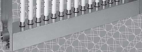
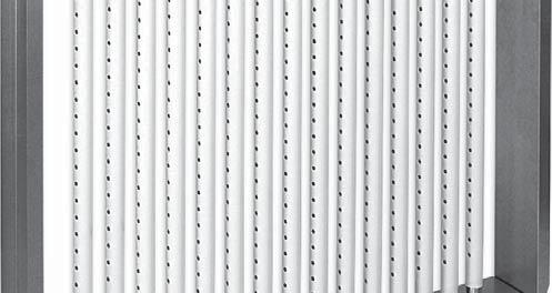
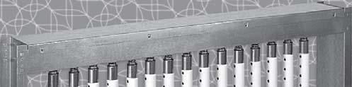
4 INSTALLATION Field assembly UNPACK THE DISPERSION ASSEMBLY Remove shipping materials from the dispersion assembly, being careful not to bump or scrape the white PVDF dispersion tube insulation. Do not lay dispersion tubes (if shipped loose by request or by shipping necessity) across or under anything that could compress or damage the insulation. Compressing insulating material may reduce its R-value. VERIFY THAT THE ORDER IS COMPLETE Verify that all panel and piping components are included in the delivery. Check the packing list, and see the tables on Page 32. Orders may include control valve(s), humidity transmitters or humidistats, airflow switches, and a control cabinet. Note the dispersion assembly serial number: The serial number will be required to ensure proper identification of replacement parts. CAUTION Remove clear poly film; do not remove white PVDF insulation. High-Efficiency Tubes are sleeved in clear poly film for protection during processing, shipping, and installation. Leave the clear poly film on until installation is complete so the insulation stays clean. Remove and discard the clear poly film before start-up by tearing it along the perforations. Do not remove the white PVDF insulation. Keep flame away from the insulating material to avoid damage. Indirect, low-intensity UV-C light from germicidal lamps will not cause the insulating material to degrade. Do not tighten mounting clamps or fasteners to any part of the dispersion tube. mc_071211_1530 2
5 INSTALLATION Field assembly LAY OUT THE PANEL COMPONENTS Orient the panel components on a large, flat working surface. ATTACH THE FLANGES Guide the flanges onto the threaded studs of the header assembly, and start the locknuts onto the threads finger-tight. Note: These assembly instructions are for Ultra-sorb Model XV panels shipped unassembled by request or as required. Panels with overall height more than 98" (2490 mm) are shipped unassembled. ATTACH THE TOP FRAME ASSEMBLY Span the flanges with the top frame assembly. Align the locating buttons on the flanges and top frame, and insert screws. TIGHTEN THE FLANGE LOCKNUTS Torque the eight flange locknuts to 16 ft-lb (22 N-m) using a 7/16" deep-well socket. INSTALL THE DISPERSION TUBES Note: Do not remove the poly film from the dispersion tubes until after the panel is installed. Ensure that each dispersion tube has the seal and spring in place (see Figure 3-1). Push the dispersion tube plug end into the top frame hole to compress the spring. Seat the seal end in the corresponding header hole on the bottom. Rotate the dispersion tubes so the tubelets discharge steam perpendicular to the airstream. See Figure 9-1. FIGURE 3-1: ULTRA-SORB MODEL XV COMPONENTS Top frame assembly Screw Spring Plug Table 3-1: Ultra-sorb Model XV components Component Header assembly 1 Dispersion tube Top frame assembly 1 Qty. Varies Insulation Dispersion tube assembly Flanges 2 Screws 8 Flange OM-7484 Ring Seal Flange locknuts 8 Flange locknut Header assembly 3
6 INSTALLATION Piping FIGURE 4-1: ULTRA-SORB MODEL XV PIPING COMPONENTS WITH ON/OFF SHUTOFF VALVE, FLOAT SWITCH, PRESSURIZED STEAM SOURCE Applications with control cabinet operating internal heat exchanger. Install inlet strainer within 3' (1 m) of Ultra-sorb Model XV. Strainer should be same pipe size or larger than modulating steam valve. 2-position shutoff valve may be smaller than strainers and modulating steam valve. From pressurized steam source Modulating steam valve 2-position shutoff valve Ultra-sorb Model XV steam dispersion panel Float switch To condensate return main Note: Dashed lines indicate provided by installer. Steam trap To condensate return main Steam trap OM-7656d FIGURE 4-2: ULTRA-SORB MODEL XV PIPING COMPONENTS WITH TEMPERATURE SWITCH, PRESSURIZED STEAM SOURCE Applications with full-time operation of internal heat exchanger. Install inlet strainer within 3' (1 m) of Ultra-sorb Model XV. Strainer should be same pipe size or larger than modulating steam valve. 2-position shutoff valve may be smaller than strainers and electric modulating steam valve. From pressurized steam source Modulating steam valve Ultra-sorb Model XV steam dispersion panel Temperature switch (install as close to heat exchanger outlet as possible) Steam trap Steam trap To condensate return main To condensate return main OM-7878 Note: Dashed lines indicate provided by installer. 4
7 INSTALLATION Piping FIGURE 5-1: ULTRA-SORB MODEL XV PIPING WITH STS HUMIDIFIER Steam to heat exchanger from pressurized steam source, humidification steam from STS humidifier Isolation valve (by others) From pressurized steam source Insulated steam supply tubing Connection end of header (see inset below) STS humidifier Cold fill water Steam trap Modulating steam valve Inlet strainer On/off valve (optional) Header Pressurized condensate to return main Dispersion tube Pressurized steam to heat exchanger Steam trap Ultra-sorb XV dispersion panel OM-7902 Steam trap To condensate return main Pressurized condensate to return main Open drain (temper to local code) Drane-kooler water tempering device Connection end of header From pressurized steam source Humidification steam from STS humidifier Float switch On-off solenoid valve OM-7654_2016 Note: Tubing union shown at steam connection. For STS humidifier, connection may also be 3" (DN80) flange. 5
8 INSTALLATION Selecting the location FIGURE 6-1: PLACING A DISPERSION ASSEMBLY IN AN AIR HANDLING UNIT Filters Economizer control device Cooling coil 10' to 15' (3 to 4.5 m) Heating coil Duct high limit humidity control for dispersion locations A, B Airflow proving switch Outside air Fan Exterior building wall Preheat coil Motorized air dampers D B A 3' to 5' (1 to 1.5 m) C Relief air 10' to 15' (3 to 4.5 m) Airflow proving switch Duct high limit humidity control for dispersion location C DC-1081 mc_092507_1530 Return airflow Supply airflow 6
9 INSTALLATION Selecting the location DETERMINE STEAM DISPERSION PANEL PLACEMENT Dispersed steam must be absorbed into the airfl ow before it comes in contact with duct elbows, fans, vanes, filters, or any object that can cause condensation and dripping. Install the Ultra-sorb panel in a location where discharged water vapor will be absorbed by the airstream. Place the Ultra-sorb panel where the air temperature is capable of absorbing discharged steam without causing condensation at or after the unit. This will normally be downstream of the heating coil where the air is warmest. Do not place the Ultra-sorb panel in an outside air intake unless the air is first tempered with a preheat coil. Do not place the Ultra-sorb panel near the entrance of a high-efficiency filter. The filter will remove visible moisture and become waterlogged. See the Caution Installing Ultra-sorb upstream from filter media on Page 28. Do not place the Ultra-sorb panel where discharged visible mist will impinge directly on a metal surface. PLACEMENT IN AN AIR HANDLING UNIT (FIGURE 6-1) Location A is the best choice. Installing downstream of heating and cooling coils provides the most even flow through the dispersion unit; plus, the heated air provides an environment for best absorption. Location B is the second-best choice. However, in change-over periods, the cooling coil will eliminate some moisture for humidification. Location C is the third-best choice. Air leaving a fan is usually very turbulent and can cause vapor to not absorb at the expected non-wetting distance. Allow for more distance if installing downstream of a fan. Location D is the poorest choice. The cooler air at this location requires an increased non-wetting distance. 7
10 INSTALLATION Mounting and support INSTALLATION IN A COLD AIR STREAM When a steam dispersion panel is installed in a duct that will carry cold air, determine the dew point temperature. If the psychrometric chart reveals that saturation may occur, protection should be provided. A high-limit humidistat or thermostat set to cut off the steam dispersion panel at a safe temperature can be used for this purpose. See Figure 8-1. FIGURE 8-1: INSTALLATION IN A COLD AIR STREAM Cold air flow Ultra-sorb Extended trails of fog may develop PLACEMENT UPSTREAM FROM AN ELBOW OR DUCT SPLIT Due to Ultra-sorb's rapid steam absorption performance, installation upstream from elbows or duct splits can be done with confidence. See Figure 8-2. High limit duct humidistat 10' to 15' (3 to 4.5 m) downstream from Ultra-sorb OM-197 mc_052411_0830 INSTALLATION ABOVE VALUABLE EQUIPMENT Water piping and humidifiers should not be installed above expensive equipment. A condensing or leaking water pipe or other accidental water spillage could cause serious damage to the equipment below. When such an installation cannot be avoided, install a galvanized drip pan under the humidifier piping, valve, etc. to catch and drain away unintended water. See Figure 8-3. See also Optional header overflow P-trap water seal on Page 17. PANEL SUPPORT The duct or air handler section and Ultra-sorb panel must be properly supported to carry the weight of the assembly. The weight of the piping must be supported by the building structure rather than by the Ultra-sorb unit. Otherwise, the weight may impose stress on the connections, causing them to fracture and leak. mc_071311_1540 FIGURE 8-2: UPSTREAM PLACEMENT Airflow Airflow Airflow Ultra-sorb Ultra-sorb OM-178 Ultra-sorb Elbow Non-wetting distance Duct split FIGURE 8-3: INSTALLATION ABOVE VALUABLE EQUIPMENT Duct Vapor absorption area Drip pan Pipe to drain size as required OM-198 2" (50 mm) Ceiling line * This length of duct should have sealed seams and should be at least three times the height of the Ultra-sorb panel. mc_101410_0955 8
11 INSTALLATION Mounting and support Where allowed, screws and drill bits must not penetrate more than 3/4" (20 mm) into the header assembly. See Figure 10-1 for allowable drill and screw locations. Ultra-sorb Model XV must be installed in horizontal airfl ows only. Duct smoke detector Do not install a duct smoke detector downstream from the Ultra-sorb panel. If downstream installation is required, install it far enough from the Ultra-sorb panel to avoid false alarms. MOUNTING IN A DUCT Mounting flanges on both sides of the unit and the header and frame can be used as mounting surfaces (see Figure 10-1). A matching flange or metal frame is required on the ductwork for connection to the Ultra-sorb flanges. Use a #12 self-drilling and tapping screw 3/4" (20 mm) long, spacing not to exceed 12" (305 mm). If an angle-iron frame is provided on the duct section, a longer screw may be required. Dispersion tube orientation Verify that the steam discharge tubelets are perpendicular to the airstream (see Figure 9-1). The spring-loaded dispersion tubes easily rotate for proper orientation. FIGURE 9-1: DISPERSION TUBE ORIENTATION MOUNTING IN AN AIR HANDLER Tubelet Dispersion tube Metal support frames should be anchored to the air handler casing. When mounting the Ultra-sorb to a metal support frame, use 1/4-20 nuts and bolts or #12 self drilling and tapping screws. Fastener spacing should not exceed 6" (150 mm). Airflow Airflow OM-150a FIGURE 9-2: PREVENTING DUCT AIR LEAKS Perimeter of top frame along duct flange Ultra-sorb panels that penetrate a duct section must be sealed with HVAC caulking or a similar weather sealant to prevent air leakage. Panels should be sealed at locations shown. Top outside corners Both sides of cover seam Four inside corners OM-7482 mc_101410_0845 9
, determined by maximum steam capacity 3\" (DN80) flange, STS humidifier connection only Pressurized condensate outlet (3/4\" NPT, internal")
12 INSTALLATION Installation drawings: Mounting in a duct FIGURE 10-1: ULTRA-SORB MODEL XV IN A DUCT (HORIZONTAL AIRFLOW ONLY) Attach duct flange to top frame assembly Connection end of header Humidification steam inlet: 1" or 2" NPT (DN25 or DN50), determined by maximum steam capacity 3" (DN80) flange, STS humidifier connection only Pressurized condensate outlet (3/4" NPT, internal thread) Float switch, optional header overflow/ access port (1/2" NPT, internal thread) Pressurized boiler steam inlet (3/4" NPT, internal thread) Screws OK No screws Screws OK Screws OK 1/2" (13 mm) Attach duct flanges to 1.5" (38 mm) mounting flanges Attach duct flange to header assembly No screws through top of header assembly 1/2" (13 mm) No screws through end of header assembly Screws OK 3/4" (20 mm) max length (See Note 7) No screws through end of header assembly OM-7490 mc_101310_1030 Add center support required for all units greater than 60" (1524 mm) wide. No screws through bottom of header assembly Notes: 1. See Figure 12-1 for trap clearance. 2. Steam supply line to unit and piping are not included. 3. Dispersion tubes are available on 3", 4", 6", 9" and 12" (76, 102, 152, 229, and 305 mm) centers. 4. Ultra-sorb steam dispersion panels will be assembled, crated, and shipped intact in all sizes up to 98" (2490 mm) overall height. Any Ultra-sorb can be shipped unassembled by request, requiring field assembly. 5. Standard sizes are 12" x 12" up to 144" x 144" in 1" increments (305 x 305 mm up to 3660 x 3660 mm in 25 mm increments). Larger sizes are available. 6. Install the panel level. If slope cannot be avoided, ensure that the slope is toward the drain end of the panel. 7. Drill or screw through the header assembly only where shown. Screws and drill bits must not penetrate more than 3/4" (20 mm) into the header assembly. Use 1/4 20 nuts and bolts or #12 self drilling and tapping screws for mounting the Ultra-sorb to a metal support frame. 10
, determined by maximum steam capacity 3\" (DN80) flange, STS humidifier connection only Pressurized condensate outlet (3/4\" NPT, internal thread) Float switch,")
13 INSTALLATION Installation drawings: Mounting in an air handler FIGURE 11-1: ULTRA-SORB MODEL XV IN AN AIR HANDLER (HORIZONTAL AIRFLOW ONLY) AHU width Connection end of header Humidification steam inlet: 1" or 2" NPT (DN25 or DN50), determined by maximum steam capacity 3" (DN80) flange, STS humidifier connection only Pressurized condensate outlet (3/4" NPT, internal thread) Float switch, optional header overflow/ access port (1/2" NPT, internal thread) Pressurized boiler steam inlet (3/4" NPT, internal thread) Tubelets perpendicular to airflow Coil width Coil height AHU height AHU wall Humidification steam to header Header OM-7657a Steam from pressurized steam source to heat exchanger Pressurized condensate out to return main Add center support required for all units greater than 60" (1524 mm) wide. Notes: 1. Dashed lines indicate provided by installer. 2. See Figures 12-1 and 12-2 for trap clearance alternatives. 3. Steam supply line to unit and piping are not included. 4. Dispersion tubes are available on 3", 4", 6", 9" and 12" (76, , 229, and 305 mm) centers. 5. Ultra-sorb steam dispersion panels will be assembled, crated, and shipped intact in all sizes up to 98" (2490 mm) overall height. Any Ultra-sorb can be shipped unassembled by request, requiring field assembly. 6. Standard sizes are 12" x 12" up to 144" x 144" in 1" increments (305 x 305 mm up to 3660 x 3660 mm in 25 mm increments). Larger sizes are available. 7. Heat exchanger requires 5 psig (35 kpa) minimum steam pressure. CAUTION Use a backup wrench Use a backup wrench on all plumbing connections. Failure to use a backup wrench could cause damage to the Ultra-sorb Model XV. Mounting in an air handling unit Metal support frames should be anchored to the air handler casing. Drill or screw through the header assembly only where shown in Figure Screws and drill bits must not penetrate more than 3/4" (20 mm) into the header assembly. Use 1/4 20 nuts and bolts or #12 self drilling and tapping screws. Fastener spacing should not to exceed 6" (150 mm). When Ultra-sorb Model XV is installed in bypass air applications provide additional bracing for the unsupported side(s). Install the panel level. If slope cannot be avoided, ensure that the slope is toward the drain end of the panel. 11
14 INSTALLATION Recommendations and steam inlets RECOMMENDATIONS Trapping - steam supply and pressurized condensate return Low pressure, up to 15 psi (103 kpa) float and thermostatic (steam) trap (Figure 12-1) High pressure, more than 15 psi (103 kpa) inverted bucket trap (Figure 12-2) Lifting condensate Steam trap (up to 15 psi/103 kpa) or inverted bucket trap (Figure 12-3) Driest steam To ensure driest steam, take humidifier steam off the top of the steam main (not the side or bottom). Airflow proving switch Use an airflow proving switch to prevent humidification steam from entering the header if air is not moving in the duct. High limit humidistat To prevent over saturation use a high limit (duct mounted) humidistat (Figure 6-1). Mount it 10' to 15' (3 to 4.5 m) downstream from the Ultra-sorb panel, and set it at 80 to 90% RH. HEAT EXCHANGER PRESSURIZED BOILER STEAM INLET (SEE FIGURE 11-1) Steam pressure for steam entering the heat exchanger must be least 5 psig (35 kpa) to vaporize condensate in the header. Integral heat exchanger Ultra-sorb Model XV employs an integral heat exchanger to pressurize and lift condensate up to 12" per psi (300 mm per 6.9 kpa) of steam pressure. Steam pressure entering the heat exchanger must be at least 5 psig (35 kpa). Condensate may be piped to the condensate return main. FIGURE 12-1: ULTRA-SORB MODEL XV STEAM TRAP DIMENSIONS 6" (152 mm) Steam trap clearance Note: Dashed lines indicate provided by installer. OM-7655 FIGURE 12-2: LIFTING CONDENSATE WITH ULTRA-SORB MODEL XV Elevated condensate return main Modulating control valve 2-position shutoff control valve Inlet strainer Ultra-sorb XV steam dispersion panel OM-7879 Steam trap Check valve (by others) 12
15 INSTALLATION Controls CONTROL OPTIONS CONFIRMING STEAM DISPERSION PANEL CONFIGURATION The Ultra-sorb XV steam dispersion panel utilizes a built-in heat exchanger to evaporate condensate generated in the humidification process. For maximum energy efficiency, this requires a unique control sequence that operates a 2-position shutoff valve for the heat exchanger, in addition to a modulating valve for humidification control. A float switch in the steam dispersion panel header, along with control sequence timings assure effective condensate management along with humidification output based on demand. Control options are described in Table CONTROL OPTION #1 - DRISTEEM CONTROL CABINET The Ultra-sorb XV dispersion panel is provided with controls by DriSteem. Operation of both the 2-position shutoff valve, and modulating control valve is coordinated by the electronic controller provided in the DriSteem control cabinet. A demand signal or space RH is sent to the DriSteem controller, and the controller opens/closes the two steam valves based on the signal and inputs including the steam dispersion panel float switch, and (optionally) a duct air flow switch and humidity high limit control. Note: The Ultra-sorb XV control cabinet utilizes the same control board as other DriSteem products, when configured as a Vapor-logic controller. The Ultra-sorb XV application firmware is different from Vapor-logic control. Board wiring terminal connections do not have the same functions as used for the Vaporlogic controller. Please refer to the wiring diagram included with the unit for proper wiring. Field configuration of the Ultra-sorb XV board is as described in the following paragraphs. Adjust the Vapor-logic control signals and setting from the Vapor-logic keypad interface or web server. Refer to the Vapor-logic IOM for further details. WARNING Electric shock hazard Only qualified electrical personnel should perform field wiring installation procedures. Improper wiring or contact with energized circuits can cause property damage, severe personal injury, or death as a result of electric shock and/or fire. Do not open control cabinet or subpanel access panels until electrical power is disconnected. CAUTION Damage from debris When drilling penetrations in the control cabinet, protect all internal components from debris, and vacuum out the control cabinet when finished. Failure to comply with this directive can damage sensitive electronic com po nents, cause erratic operation or failure, and void your DriSteem warranty. Important: Failure to follow these wiring procedures can result in erratic operation or failure. This product has been tested at the factory for proper operation. Product failures resulting from faulty handling, incorrect wiring, or shorting of wires together on external components are not covered under your DriSteem warranty. Review information and di a grams before proceeding. 13
16 INSTALLATION Controls FLOAT SWITCH Wire the float switch to the DriSteem control cabinet. A wiring diagram is included with the unit. Under normal conditions the float switch in the Ultra-sorb Model XV header is closed, and the modulating steam valve or STS humidifier operates according to the humidification control system s call for humidity. In the event condensate levels rise in the humidifier header, the float switch rises and the circuit opens, activating a condensate mitigation sequence. Refer to the sequence of operation on page 33. If you suspect problems with the float switch operation, see float switch maintenance instructions on Page 31. These instructions must be followed for the float switch to function properly. AIR FLOW SWITCH Air flow indication is required. Indication can be provided by a BAS input or air flow switch wired to the DriSteem control cabinet. Wire the air flow switch to the DriSteem control cabinet as shown in the diagram included with the unit. The steam dispersion panel will not run if the air flow switch input of the DriSteem controller is left open. A circuit-closing jumper is provided on the controller board input and must be removed to the air flow input. HIGH LIMIT HUMIDISTAT Wire the duct high limit humidistat to the DriSteem control cabinet. Refer to the Vapor-logic external connections diagram or the Vapor-logic IOM for wiring instructions. 14
17 INSTALLATION Controls CONTROL OPTION #2 ELECTRIC TEMPERATURE SWITCH ONLY; CONTINUOUS HEAT EXCHANGER OPERATION The DriSteem control cabinet is not provided. An electric modulating control valve is controlled by a 2-10 VDC/4-20 ma signal from a control system (BAS) or modulating humidistat. Optional air flow switch, high limit humidistat are wired in series with 24 VAC control circuit of the modulating control valve. See the wiring diagrams provided with the unit. ELECTRIC TEMPERATURE SWITCH Install the temperature switch (Figure 20-1) to prevent the header from flooding with condensate if the heat exchanger cools, such as if the condensate return main becomes flooded or the trap fails closed. DriSteem's temperature switch is a temperature-actuated make-break switch. The temperature at which it switches is adjustable and should be set at 210 F (99 C). Install the sensing element of the temperature switch in the condensate return piping between the Ultra-sorb heat exchanger outlet and the inlet to the steam trap, as shown in Figure Include a tee with a 1/2" (DN15) pipe thread opening to receive the sensing element. When steam surrounds the sensing element, the switch will make, allowing the steam dispersion panel valve to open. Install all wiring according to national and local electrical codes, and size transformer VA to load VA. When using a temperature switch to control the on-off heat exchanger valve, follow the wiring instructions supplied with the modulating humidification-steam control valve. CONTROL OPTION #3 PNEUMATIC TEMPERATURE SWITCH ONLY; CONTINUOUS HEAT EXCHANGER OPERATION The DriSteem control cabinet is not provided. A pneumatic modulating control valve is sent a 3-15 PSI signal from a pneumatic humidistat or other pneumatic device, to modulate the valve based on humidity demand. The 2-position shutoff valve is not used. Steam supply to the panel s internal heat exchanger is continuous. PNEUMATIC TEMPERATURE SWITCH Install the pneumatic temperature switch as shown in (Figure 20-2). The temperature switch will prevent the header from flooding with condensate by closing the modulating steam valve if the heat exchanger cools (if the condensate return main becomes flooded or the trap fails closed). DriSteem's pneumatic temperature switch is a temperature-actuated openclosed pneumatic switch. The pneumatic signal (3-15 PSI) is maintained above 210 F (99 C) and is opened (bled off) below 200 F (93 C). 15
18 INSTALLATION Controls CONTROL OPTION #4 CONTROLS BY BAS/CONTROLS CONTRACTOR The BAS or controls contractor will provide the necessary controller and programming logic to sequence the steam dispersion panel valves as described for Control Option #1. This includes providing control outputs for the modulating control valve and 2-position shutoff valve. Refer to the BAS controls contractor wiring diagrams for specific valve and float switch connection terminals. Table 16-1: Boiler steam application control options Heat exchanger and humidifier control option 2-position shutoff valve Modulating control valve Float switch in header Temperature switch at condensate outlet DriSteem control cabinet Control Cabinet with time delay (#1) Coordinated Heat exchanger and humidification control through DriSteem control cabinet. Electric - Wired to DriSteem control cabinet Electric - Wired to DriSteem control cabinet Yes - Wired to control cabinet No (optional) Yes Temperature switch only (Electric) (#2) The heat exchanger operates continuously (100%). Electric temperature switch opens, shutting off the power to the modulating valve if the condensate backs up in the heat exchanger (failed trap). Not Used Electric No Yes- Electric No Temperature switch only (Pneumatic) (#3) The heat exchanger operates continuously (100%). Pneumatic temperature switch opens, closing the modulating valve if the condensate backs up in the heat exchanger (failed trap). Not Used Pneumatic No Yes - Pneumatic No BAS Control (#4) Controls by BAS/controls contractor; Contractor to provide and follow control sequence of Control Option #1 Electric - Wired to BAS controller Electric - Wired to BAS controller Yes - Wired to BAS controller No (optional) No Control by STS humidifier (#5) Control by STS humidifier Optional if chosen with Ultra-sorb XV Chosen for inlet to STS - Electic or Pneumatic Yes - Wired to STS humidifier Vapor-logic controller Optional if chosen with Ultra-sorb XV No - Control provided by STS humidifier 16
19 INSTALLATION Controls ULTRA-SORB XV WITH DRISTEEM STEAM-TO-STEAM (STS) HUMIDIFIER If the Ultra-sorb XV panel is used in conjunction with a DriSteem Steam-to- Steam (STS) humidifier, atmospheric steam generated from the STS is piped to the Ultra-sorb XV and distributed through the dispersion header to the humidifier tubes. Pressurized boiler steam (5 PSI minimum), as used to source the STS unit heat exchanger, is also used to operate the Ultra-sorb XV internal heat exchanger enabling condensate evaporation in the humidifier panel header. See Figure 5-1 for piping connections. FIGURE 17-1: ULTRA-SORB MODEL XV CONTROL CABINET 12" (305 mm) 12" (305 mm) Optional Ultra-sorb XV control devices are located as shown in Figure 5-1 and wired to the Vapor-logic controller provided with the associated STS humidifier. Devices may include a 2-position solenoid valve for XV heat exchanger control, and float or temperature switch(es). 6" (152 mm) OM-7533 Refer to the wiring diagram provided with the STS unit for wiring connections. OPTIONAL HEADER OVERFLOW P-TRAP WATER SEAL Ultra-sorb Model XV is designed to vaporize the condensate generated in a properly designed, installed, operated, and maintained system. An optional, header overflow p-trap (Figure 17-2) is recommended if any of the following are true: There is not a float switch installed in the dispersion panel header. Boiler chemicals are causing heavy material deposition on heat exchanger. Before operating the Ultra-sorb, and after extended shutdown periods, prime the P-trap with about 1 cup (200 ml) of water. A water seal cannot be assured via condensate generated within the humidifier header. Do not feed the P-trap with a water source to maintain prime, as this will force water into the header. Notes: Electrical power requirements: 120 VAC, 1.0 Amps, or 230 VAC, 0.5 Amps Components are 24 VAC, powered by a transformer in the control cabinet. 50 VA available from internal transformer for operation of two 24 VAC control valves. Maximum distance from control cabinet to Ultra-sorb Model XV is 50 (15 m). FIGURE 17-2: ULTRA-SORB MODEL XV OPTIONAL HEADER OVERFLOW P-TRAP WATER SEAL Connection end of header Connect optional P-trap overflow water seal if float switch is not used. 1.25" (32 mm) rise Fill cap 12" (305 mm) seal 10.75" (273 mm) OM-7493 Note: After the water seal, run a 1½" (DN40) drain line to an open drain with a 1" (25 mm) air gap. Water seal must cover height of internal heat exchanger tube as shown to provide condensate evaporation in normal operating conditions. 17
20 INSTALLATION Controls FIGURE 18-1: CONTROL CABINET Status LED Controller board Wiring terminal block OM /208/240/480V to 24 VAC transformer, 75 VAC 18
21 OPERATION Ultra-sorb XV operation 1. STEAM SUPPLY INLET Humidification steam from the modulating steam valve (Figure 4-2) or STS humidifier (Figure 19-1) passes through the steam supply inlet into the Ultra-sorb header. 2. HEADER Humidification steam flows through the insulated header, up the High- Efficiency Tubes, and into the airstream. FIGURE 19-1: ULTRA-SORB MODEL XV WITH STS; STEAM INLETS DETAILED Humidification steam from STS steam-to-steam humidifier From pressurized steam source 3. HEAT EXCHANGER Pressurized steam enters the heat exchanger inlet. The heat exchanger vaporizes dispersion-generated condensate, while pressurized condensate returns to the boiler via the condensate return main. OM-7654-inlets Note: Dashed lines indicate provided by installer. 19
22 OPERATION Ultra-sorb XV operation TEMPERATURE SWITCH The temperature switch circuit s sequence of operation is a safety sequence: In the unlikely event that excessive header condensate cools the heat exchanger while humidifying, the temperature sensor drops below operating temperature, and the switch opens. This signals the modulating steam valve or STS humidifier control system to stop humidification steam from entering the header and prevents further condensate production. See the temperature switch sensor in Figure 20-1 and Figure FIGURE 20-1: ELECTRIC TEMPERATURE SWITCH Electric temperature switch (install as close to heat exchanger outlet as possible) Note: Dashed lines indicate provided by installer. OM-7536 FIGURE 20-2: PNEUMATIC TEMPERATURE SWITCH Pneumatic temperature switch Pneumatic valve Restrictor.007 dia. orifice Pneumatic supply by others 0-20 psi (0-138 kpa) XV-4 20
23 OPERATION Sequence of operation FIGURE 21-1: CONTROL COMPONENTS - CONTROL OPTION #1 2-position (ON/OFF) shutoff control valve with end switch Modulating control valve Ultra-sorb XV steam dispersion panel Control cabinet 2-10V/4-20mA humidification demand signal from BAS or humidistat 120V/230V 1 amp/0.5 amp power Diagnostic/ alarm output(s) to BAS (optional) Inlet strainer Trap OM-7880 Float switch Important: If the steam valve and heat exchanger control is to be provided directly by a separate BAS controller (Control Option #4 without use of DriSteem control cabinet), inputs and valve output controls must be linked to a BAS controller and sequenced as described below. DRISTEEM CONTROL CABINET INCLUDING 2-POSITION SHUTOFF VALVE AND FLOAT SWITCH The following control sequence is accomplished through use of the DriSteem control cabinet to provide maximum energy efficiency and operational reliability, through proper timing of operation of the 2-position (on-off) shutoff valve, and modulating control valve. Required inputs include demand signal, and safety interlocks of air flow and header/heat exchanger float switch. 1. Upon air handling unit startup (Occupied Mode), air flow switch enables 2-position (On-Off), normally closed, spring return shutoff valve actuator. Start/stop of fan provided by BAS or other control command. a. If air flow interlock is provided by BAS, then the BAS must provide a contact closure to the DriSteem control cabinet air flow switch input. 2. The 2-position (On/Off) shutoff valve opens only if air flow is detected, and if demand for humidification is present. 21
24 OPERATION Sequence of operation 3. Humidification demand is provided by a control signal to the DriSteem control cabinet. When the demand signal is sufficient, steam will flow to 1) the internal heat exchanger and 2) the modulating control valve that provides steam output based on demand. 4. As the 2-position shutoff valve opens (approx. 75 seconds), the heat exchanger in the steam dispersion panel begins operating. The heat exchanger will continue to operate any time there is duct air flow and humidification demand. 5. The shutoff valve actuator includes an end switch that enables the modulating control valve if the shutoff valve is over 90% open. The end switch of the shutoff valve actuator is wired to an input of the steam dispersion panel controller. If the input is not made, the modulating control valve will remain closed. 6. If the shutoff valve does not reach 90% open after 4 minutes (determined by actuator end switch), the steam dispersion panel controller will close the shutoff valve and activate a failure alarm contact on the control board, and provide LED alarm indication on the controller. See Figure 21 [DriSteem alarm point to be wired to BAS as specified.] 7. When the steam dispersion panel controller verifies the shutoff valve is open, it allows the modulating control valve to modulate based on the control signal, providing a 2-10 VDC signal from the control board to the valve actuator. At low/no demand signal or space RH above setpoint and outside the PID band, the valve is closed. At high demand or space RH below setpoint, the valve opens. Modulating control valve is spring-return to fail to the closed position. 8. When the air handling unit fan stops (Unoccupied Mode by command of BAS, or other means) the air flow input wired to the steam dispersion panel controller opens, and controller returns the modulating control valve to the closed position. 9. After the modulating control valve is closed, the 2-position shutoff valve remains open, to maintain steam flow through the heat exchanger for 15 minutes to evaporate any remaining condensate in the steam dispersion panel header. 22
25 OPERATION Sequence of operation 10. After fifteen minutes of heat exchanger operation, the 2-position shutoff valve will close (Twenty-five second close time). The end switch of the shutoff valve opens to assure the modulating control valve is closed whenever the heat exchanger is off. 11. A float switch is located in the steam dispersion panel header, and wired to the DriSteem controller. The switch circuit will open if condensate (water) depth in the header rises 1/2 above the heat exchanger tube. a. If the condensate level rises above the float switch point, the controller drives the modulating control valve closed, stopping steam flow and the possibility of condensate generation. 12. The steam dispersion panel controller monitors the elapsed time starting when a high condensate level occurs. 13. If the header condensate level falls below the float switch height, the modulating valve will resume normal control as set by BAS/control input. 14. If the level remains at/above the switch, the modulating valve will remain closed. 15. The time interval for condensate management will increase each time the level is exceeded. The time provided to lower/evaporate condensate is initially 2 minutes, and increases by 1 minute intervals each time the condensate level is exceeded, to fifteen minutes maximum. 16. If the condensate level stays below the float switch for more than fifteen minutes, the incremental timer will be reset. 17. If the incremental timer cycle (2 minutes through fifteen minute iterative cycle) is exceeded, and if condensate has not remained below the condensate level switch, the 2-position shutoff valve will be closed. The controller will activate diagnostic outputs (1 NC/ 1 NO) to indicate condensate clearing failure. (The controller provides on-board diagnostic LED to indicate Condensate Clearing Failure (see page 25). 18. If the power is reset or interrupted to the unit the entire sequence will be re-initiated. 23
26 OPERATION Sequence of operation FULL-TIME HEAT EXCHANGER OPERATION WITH ELECTRIC OR PNEUMATIC TEMPERATURE SWITCH With control options #2 and #3, a 2-position (On-Off) shutoff control valve is not used (see Figure 4-2). The Ultra-sorb XV internal heat exchanger operates any time pressurized steam is available to the dispersion panel. Install the temperature switch downstream of the internal heat exchanger to prevent operation of the modulating control valve if steam is not flowing through the heat exchanger. 1. Upon air handling unit startup (Occupied Mode), air flow switch enables modulating control valve. Start/stop of fan provided by BAS or other control command. a. If air flow interlock is provided by BAS, then the BAS must provide a contact closure in series with the modulating valve 24 VAC power circuit as shown on the wiring diagram shipped with the Ultra-sorb panel. 2. Humidification demand is provided by a 2-10VDC/4-20mA signal from BAS/control signal or humidistat, to the modulating control valve. 3. Internal heat exchanger operates continuously. A temperature switch (electric or pneumatic) senses condensate temperature leaving the heat exchanger. If the temperature at the outlet of the heat exchanger falls below 210 F (99 C), the temperature switch closes the modulating control valve to prevent condensate buildup in the steam dispersion panel header. 24
27 OPERATION Sequence of operation CONTROL CABINET STATUS LED The control board within the control cabinet includes a large Status LED that indicates multiple control conditions (see Figure 18-1). The Status LED is always blinking. It will be easy to see that the board is powered and operating because, at a minimum, it is running the Status LED. The blinking will be in a 3-stage cycle starting from being dark, with the LED brightness illuminating up to the first stage of indication. Timing of the 3-stage cycle will be over approximately four seconds. CONTROL BOARD LED - DIAGNOSTIC CODES First Blink (long):wiring Interlocks Green OK Yellow Interlock circuit open: duct high RH limit or no air flow Red On/Off shutoff valve: end switch failed to close (Manual Reset- Cycle Power) Second Blink: Green Yellow Red Third Blink: Blue Green Yellow Condensate level status OK System clearing condensate (>1 depth in header) Condensate clearing failure (Manual Reset- Cycle Power) Humidification demand No humidification demand Humidification demand to controller Clearing condensate: waiting to open control valve Note: A list of the diagnostic codes are in the control cabinet. 25
28 OPERATION Sequence of operation CONTROL BOARD ALARM OUTPUTS There are 2 dry contact outputs on the control board that can provide alarm indications to a BAS or other control system. Terminals C-1 to NO-1 are normally open and close upon alarm condition(s) Terminals C-2 to NO-2 are normally closed and will open upon alarm condition(s) The conditions under which the alarm conditions occur are: If the shutoff valve does not reach 90% open after 4 minutes (actuator end switch), then the steam dispersion panel controller will close the shutoff valve and activate the diagnostic alarm contact If the condensate timer cycle (2 minutes through 15 minute iterative cycle) is exceeded, and if condensate has not remained below the condensate level switch, the 2-position shutoff valve will be closed. The controller will activate the diagnostic alarm contacts to indicate condensate clearing failure. Dry contacts are rated for 125 VAC, 3 AMP or 30 VDC, 3 AMP maximum. Exceeding this maximum rating can cause the dry contact (relay) component or the control board to fail. 26

29 OPERATION Start-up checklist 1. Ensure all component wiring and piping connections are complete as shown in the wiring diagrams provided with the unit. 2. Create demand for humidification by providing a demand signal to control cabinet option 1 or control valves options 2 and Prime the header overflow P-trap, if installed. Ensure that it is installed as recommended in Optional header overflow P-trap water seal on Page Turn on steam to the heat exchanger. Inspect connections for piping leaks. 5. Turn on the modulating steam valve, and check for piping leaks. 6. Ensure that the traps are operating. 7. Check the dispersion tubes for leaks. 8. Ensure that the dispersion tubes are oriented with the tubelets at a right angle to the airflow. See Figure Check for any other leaks from header connections. 10. If a temperature switch is installed (control options #2 or #3), with both heat exchanger and humidification steam turned on, turn off steam to the heat exchanger. Make sure the temperature switch turns off the modulating steam valve to stop humidification steam from entering the dispersion assembly. Depending on the installation, it may take several minutes for the steam valve to close. 11. Heat exchanger operation: Ensure operating steam pressure is at least 5 psig (35 kpa). Ensure on-off and shut-off delay (15 minutes after non humidifier demand - control options #1 or #4) conditions are working as intended. CAUTION Remove clear poly film; do not remove white PVDF insulation. High-Efficiency Tubes are sleeved in clear poly film for protection during processing, shipping, and installation. Tear the clear poly film along the perforations, and remove and discard it before start-up. 27
30 OPERATION Performance data NON-WETTING DISTANCE Non-wetting distance is the dimension downstream from the leaving side of the steam dispersion assembly to the point where wetting of other components will not occur. Current design conditions may vary from conditions used for system design. The rise in RH (ΔRH) between entering and leaving air has a direct bearing on the non-wetting distance. As the ΔRH increases, more vapor needs to be dispersed into the air; thus, the non-wetting distance increases. Uneven airflow over the Ultra-sorb panel cross-section may result in nonuniform mixing of steam with air, which may increase absorption distance. A small amount of duct air pressure loss will be present downstream from the Ultra-sorb panel, depending on air density, velocity, and tube spacing. See Table CAUTION Do not install an Ultra-sorb upstream from filter media. If you must install upstream from filter media, consult DriSteem or your local DriSteem representative for recommendations. Table 28-2: Ultra-sorb XV air pressure loss Duct air velocity (55 F [13 C] at sea level) Tube spacing 3" (75 mm) - 1.5" (38 mm) tube 4" (102 mm) - 2" (50 mm) tubes 6" (150 mm) - 1.5" (38 mm) tube fpm m/s wc Pa wc Pa wc Pa Notes: Ultra-sorb panels with 9" (225 mm) or 12" (300 mm) tube spacings have no measurable air pressure loss. Use DriSteem s DriCalc sizing and selection software to calculate your specific air pressure loss. 28
31 MAINTENANCE Strainer, traps, and valves STRAINER Inspect at least twice during the first year. If fouled, inspect more frequently. STEAM TRAPS Verify that the steam traps are functioning properly at least twice a year. A blocked steam trap will be at room temperature. A blowing steam trap is hot and noisy, and the discharge pipe from it is hot for up to 30 feet (9 m). A properly operating steam trap is hot and makes noise at intervals, and the discharge pipe is progressively cooler beginning at the trap. HEADER OVERFLOW P-TRAP WATER SEAL If this option is used (see Optional header overfl ow P-trap water seal on Page 17), prime the P-trap with about 8 ounces (200 ml) of water whenever the panel has been idle for 90 days or more. VALVES Electric: Inspect annually to be sure the valve operates freely, closes off steam tightly, and there are no leaks. Pneumatic: Inspect annually to be sure the valve tightly closes off steam, the stem packing is not leaking steam, and the actuator diaphragm is not leaking air. 29
32 MAINTENANCE Dispersion tubes and heat exchanger DISPERSION TUBES If steam or condensate is evident at the sealing surface, replace the seal. Inspect insulating material for dirt and smudges; gently clean with damp cloth and soapy water or diluted nontoxic, biodegradable cleaner/ degreaser. Do not clean insulating material with a pressure washer; direct spray could cause damage. 30
33 MAINTENANCE Humidifi er de-scaling solution HEAT EXCHANGER A poor quality steam source may cause a buildup of deposits on the heat exchanger which will require periodic cleaning. After 2000 hours of operation, remove a dispersion tube and check whether the heat exchanger is coated with material deposits. Material deposits can be removed from the heat exchanger with DriSteem s Humidifier De-scaling Solution, available from your DriSteem representative. It is the only cleaner/de-scaler approved for use with DriSteem humidifiers. Use of other cleaners/de-scalers may void your DriSteem warranty. The Usage Instructions shipped with the DriSteem Humidifier De-scaling Solution contain important handling, mixing, timing, and ph testing information. The following additional instructions are for Ultra-sorb Model XV humidifier: 1. If a float switch is installed: Note position of orientation mark (see Figure 31-1). Mark must be in same position when float switch is re-installed. Remove float switch; the ½" NPT (DN15) port will be used to drain header. 2. Install a ½" NPT thread drain hose in ½" NPT (DN15) port. After making sure hose can reach a bucket or drain, elevate end of hose well above connection. See DriSteem s Humidifier De-scaling Solution on the Accessories and options page (under Products) on our website: WARNING Humidifier De-scaling Solution is corrosive. Read and follow all warnings and instructions shipped with the DriSteem Humidifier De-scaling Solution. FIGURE 31-1: ORIENTATION MARK ON FLOAT SWITCH Connection end of header Important: Check position of orientation mark before removing float switch. Mark must be in same position after re-installation for float switch to function properly. Orientation mark on float switch - normally closed (NC) must face directly upward. 3. Remove a dispersion tube, and add water to header to submerge heat exchanger (see Figure 31-2). 4. Add 10 ounces of Humidifier De-scaling Solution per foot of header length (30 ml of solution per 300 mm of header length). A 12-foot (3660 mm) header requires about 1 gallon (3.8 litres) of solution. 5. After performing de-scaling procedure as described in Usage Instructions and before resuming operation: Flush and drain header four times to thoroughly remove Humidifier De-scaling Solution from system. 6. Re-install float switch in port. mc_063011_0945 FIGURE 31-2: HEADER CROSS SECTION Pour water into header through dispersion tube hole to submerge heat exchanger before adding Humidifier De-scaling Solution. Fill water OM-7492 Heat exchanger tube inlet and outlet 31
Ultra-sorb Model XV. Installation, Operation, and Maintenance Manual. Steam Dispersion Panel. For pressurized steam applications
 Ultra-sorb Model XV Steam Dispersion Panel Installation, Operation, and Maintenance Manual For pressurized steam applications Table of contents WARNING! Steam humidification systems have extremely hot
Ultra-sorb Models LV and LH
 Ultra-sorb Models LV and LH Steam Dispersion Panels Installation, Operation, and Maintenance Manual For applications using steam from a boiler or from any DRI-STEEM steam generating humidifier. Overview
Ultra-sorb Steam Dispersion Tube Humidifier Panel
 Ultra-sorb Steam Dispersion Tube Humidifier Panel Installation, Operation, and Maintenance Manual For applications using steam from a boiler or from any DRI-STEEM steam generating humidifier. Table of
ULTRA-SORB. Installation, Operation, and Maintenance Manual MODEL. Steam Dispersion Panels
 READ AND SAVE THESE INSTRUCTIONS ULTRA-SORB MODEL MP Steam Dispersion Panels Installation, Operation, and Maintenance Manual For applications using steam from a boiler or from any DriSteem steam generating
Ultra-sorb Steam Dispersion Panels
 Ultra-sorb Steam Dispersion Panels PR0DUCT CATALOG Ultra-sorb Model LH Ultra-sorb Model LV Ultra-sorb Model XV DRI-STEEM takes the lead again with Ultra-sorb, establishing the industry standard for energy
Steam Injection Humidifiers for use with steam boilers PR0DUCT CATALOG
 Steam Injection Humidifiers for use with steam boilers PR0DUCT CATALOG Suitable for a wide range of applications Steam Injection humidifiers from DRI-STEEM use steam from an external source, such as an
ULTRA-SORB STEAM DISPERSION TUBE HUMIDIFIER PANEL
 READ AND SAVE THESE INSTRUCTIONS This manual must be left with the owner and should be accessible for reference. ULTRA-SORB STEAM DISPERSION TUBE HUMIDIFIER PANEL For Applications Using Steam From A Boiler
Steam Injection Humidifiers for use with steam boilers PRODUCT CATALOG
 Steam Injection Humidifiers for use with steam boilers PRODUCT CATALOG Suitable for a wide range of applications Steam Injection humidifiers from DRI-STEEM use steam from an external source, such as an
XT Series Electrode Steam Humidifier. Installation, Operation, and Maintenance Manual
 XT Series Electrode Steam Humidifier Installation, Operation, and Maintenance Manual ATTENTION INSTALLER Read this manual before installing humidifier. Leave manual with product owner. DRI-STEEM technical
Steam Humidifier Models 1150 and 1160
 Humidifier Steam Humidifier Models 1150 and 1160 Installation, Operation, and Maintenance Manual READ AND SAVE THESE INSTRUCTIONS TABLE OF CONTENTS PRODUCT OVERVIEW.............................. 3 Materials
Vapormist Electric Humidifier. Installation, Operation and Maintenance Manual
 Vapormist Electric Humidifier Installation, Operation and Maintenance Manual ATTENTION INSTALLER Read this manual before installing. Leave manual with product owner. DRI-STEEM technical support 800-328-4447
STS Steam-to-Steam Humidifier
 IMPORTANT: Read and save these instructions. STS Steam-to-Steam Humidifier Installation, Operation, and Maintenance Manual Warnings and cautions WARNING Indicates a hazardous situation that could result
Steam Injection Pressurized Steam Humidifiers. Installation, Operation, and Maintenance Manual
 Steam Injection Pressurized Steam Humidifiers Installation, Operation, and Maintenance Manual Safety precautions ATTENTION INSTALLER Read this manual before installing. Leave manual with product owner.
CRUV. Electric Humidifier. Installation, Operation, and Maintenance Manual
 CRUV Electric Humidifier Installation, Operation, and Maintenance Manual ATTENTION INSTALLER Read this manual before installing. Leave manual with product owner. DRI-STEEM technical support 800-328-4447
Steam Injection Humidifiers for use with steam boilers. Installation, Operation, and Maintenance Manual
 Steam Injection Humidifiers for use with steam boilers Installation, Operation, and Maintenance Manual ATTENTION INSTALLER Read this manual before installing. Leave manual with product owner. Where to
Steam Injection Pressurized Steam Humidifiers. Installation, Operation, and Maintenance Manual
 Steam Injection Pressurized Steam Humidifiers Installation, Operation, and Maintenance Manual ATTENTION INSTALLER Read this manual before installing. Leave manual with product owner. DRI-STEEM technical
SPECIFICATION DIVISION 23 SECTION DESCRIPTION DIVISION 23 HEATING, VENTILATING AND AIR CONDITIONING (HVAC) SECTION STEAM HUMIDIFIERS
 SECTION STEAM HUMIDIFIERS") ARCHITECTURE, ENGINEERING AND CONSTRUCTION P00000000 0000 DOCUMENTS ARCHITECTURE & ENGINEERING 326 East Hoover, Mail Stop B Ann Arbor, MI 48109-1002 Phone: 734-764-3414 Fax: 734-936-3334 SPECIFICATION
ARCHITECTURE, ENGINEERING AND CONSTRUCTION P00000000 0000 DOCUMENTS ARCHITECTURE & ENGINEERING 326 East Hoover, Mail Stop B Ann Arbor, MI 48109-1002 Phone: 734-764-3414 Fax: 734-936-3334 SPECIFICATION
INSTY-PAC EXTERNAL MOUNT WELDED MULTIPLE TUBE ASSEMBLY
 Read and Save These Instructions Sheet No. LSIP-EM INSTY-PAC EXTERNAL MOUNT WELDED MULTIPLE TUBE ASSEMBLY INSTALLATION AND ASSEMBLY INSTRUCTIONS Fig. 1 Tube Support AHU/Duct Injection Tube Strainer Typ.
INSTY-PAC INTERNAL MOUNT WELDED MULTIPLE TUBE ASSEMBLY
 Read and Save These Instructions Sheet No. LSIP-IM INSTY-PAC INTERNAL MOUNT WELDED MULTIPLE TUBE ASSEMBLY INSTALLATION AND ASSEMBLY INSTRUCTIONS Fig. 1 Strainer Secure to AHU/duct casing with 3/8-16 UNC
READ AND SAVE THESE INSTRUCTIONS XT SERIES. Electrode Steam Humidifiers. Installation, Operation, and Maintenance Manual
 READ AND SAVE THESE INSTRUCTIONS XT SERIES Electrode Steam Humidifiers Installation, Operation, and Maintenance Manual Warnings and cautions WARNINGS AND CAUTIONS WARNING Indicates a hazardous situation
LTS Liquid-to-Steam Humidifier. Installation, Operation and Maintenance Manual
 LTS Liquid-to-Steam Humidifier Installation, Operation and Maintenance Manual Overview LTS models....3 Dimensions....4 Output capacities....6 Weights, connections and heated water properties.... 7 Installation
XT SERIES. Electrode Steam Humidifiers. Easy to maintain Adaptable Comprehensive control with Vapor-logic option
 XT SERIES Electrode Steam Humidifiers Easy to maintain Adaptable Comprehensive control with Vapor-logic option Cost-effective steam humidification XT Series electrode steam humidifiers from DriSteem provide
READ AND SAVE THESE INSTRUCTIONS HUMIDI-TECH. Electric Humidifier. Installation, Operation, and Maintenance Manual
 READ AND SAVE THESE INSTRUCTIONS HUMIDI-TECH Electric Humidifier Installation, Operation, and Maintenance Manual WARNINGS AND CAUTIONS Warnings and cautions WARNING Indicates a hazardous situation that
Residential Steam Humidifier
 Residential Steam Humidifier Model HUMXXSTM3034 Residential Steam Humidifier Owner s Manual Includes Safety & Operating Instructions READ AND SAVE THESE INSTRUCTIONS TABLE OF CONTENTS Safety... 2 Introduction...
READ AND SAVE THESE INSTRUCTIONS XTR. Electrode Steam Humidifier. Installation, Operation, and Maintenance Manual
 READ AND SAVE THESE INSTRUCTIONS XTR Electrode Steam Humidifier Installation, Operation, and Maintenance Manual Warnings and cautions WARNINGS AND CAUTIONS WARNING Indicates a hazardous situation that
READ AND SAVE THESE INSTRUCTIONS STS. Steam-to-Steam Humidifier. Installation, Operation, and Maintenance Manual
 READ AND SAVE THESE INSTRUCTIONS STS Steam-to-Steam Humidifier Installation, Operation, and Maintenance Manual WARNINGS AND CAUTIONS Warnings and cautions WARNING Indicates a hazardous situation that could
Installation Instructions. Operation and Maintenance Manual
 TM READ AND SAVE THESE INSTRUCTIONS Deionized, Demineralized, or Reverse Osmosis Water SXDDR Series Steam Heat Exchanger Humidifier Installation Instructions Operation and Maintenance Manual Our results
READ AND SAVE THESE INSTRUCTIONS XT SERIES. Electrode Steam Humidifiers. Installation, Operation, and Maintenance Manual
 READ AND SAVE THESE INSTRUCTIONS XT SERIES Electrode Steam Humidifiers Installation, Operation, and Maintenance Manual Warnings and cautions WARNINGS AND CAUTIONS WARNING Indicates a hazardous situation
XTR Electrode Steam Humidifier. Installation, Operation, and Maintenance Manual
 XTR Electrode Steam Humidifier Installation, Operation, and Maintenance Manual Safety precautions ATTENTION INSTALLER Read this manual before installing humidifier. Leave manual with product owner. DRI-STEEM
READ AND SAVE THESE INSTRUCTIONS VAPORMIST. Electric-to-Steam Humidifier. Installation, Operation, and Maintenance Manual
 READ AND SAVE THESE INSTRUCTIONS VAPORMIST Electric-to-Steam Humidifier Installation, Operation, and Maintenance Manual WARNINGS AND CAUTIONS Warnings and cautions WARNING Indicates a hazardous situation
CUFFED FAST-PAC EXTERNAL MOUNT MULTIPLE TUBE ASSEMBLY
 TM READ AND SAVE THESE INSTRUCTIONS CUFFED FAST-PAC EXTERNAL MOUNT MULTIPLE TUBE ASSEMBLY INSTALLATION AND ASSEMBLY INSTRUCTIONS Fig. 1 Flex connectors (by PURE) AHU/duct casing Injection tube Stainless
XT SERIES. Electrode Steam Humidifiers. Easy to maintain Adaptable Comprehensive control with Vapor-logic option
 XT SERIES Electrode Steam Humidifiers Easy to maintain Adaptable Comprehensive control with Vapor-logic option Cost-effective steam humidification Model XTP XT Series electrode steam humidifiers from DriSteem
INSTY-PAC EXTERNAL MOUNT MULTIPLE TUBE ASSEMBLY
 Read and Save These Instructions Sheet No. EMIP INSTY-PAC EXTERNAL MOUNT MULTIPLE TUBE ASSEMBLY INSTALLATION AND ASSEMBLY INSTRUCTIONS Fig. 1 Tube support AHU/duct Injection tube Typ. centers Flexible
VAPORSTREAM. Electric-to-Steam Humidifier. With Vapor-logic controller Web-enabled access Interoperability via Modbus or optional BACnet or LonTalk
 VAPORSTREAM Electric-to-Steam Humidifier With Vapor-logic controller Web-enabled access Interoperability via Modbus or optional BACnet or LonTalk High-performance humidification APPLICATION VERSATILITY
READ AND SAVE THESE INSTRUCTIONS SEISMIC. Cer tification Option. Installation Manual
 READ AND SAVE THESE INSTRUCTIONS SEISMIC Cer tification Option Installation Manual Warnings and cautions Indicates a hazardous situation that could result in death or serious injury if instructions are
Steam Humidification Light Commercial Applications. Better technology means better business.
 Steam Humidification Light Commercial Applications Better technology means better business. Aprilaire Steam Humidifiers are built to last. Through extensive research and over 50 years expertise in humidification
THE SIX STEPS OF HUMIDIFICATION DESIGN
 THE SIX STEPS OF HUMIDIFICATION DESIGN To help you better understand the humidification process, this issue of Engineering Humidification will walk you through the basic steps of humidification system
Vaporstream Electric Humidifier. Installation, Operation, and Maintenance Manual
 Vaporstream Electric Humidifier Installation, Operation, and Maintenance Manual Warnings and cautions WARNING Indicates a hazardous situation that could result in death or serious injury if instructions
Insty-Pac Steam Humidifiers
 IP-1 Insty-Pac Steam umidifiers The PURE umidifier Co. Insty-Pac (patent no. 6,065,740) steam injection humidifier is jobengineered to assure highly efficient steam release into the air stream. Each humidifier
ES Series Electric Humidifier
 Read and Save These Instructions Standard Water ES Series Electric Humidifier Installation Instructions Operation and Maintenance Manual ETL LISTED HUMIDIFIER Our results are comforting Form No: ESOM-08-08
EVAPORATIVE COOLING AND HUMIDIFICATION. High-Pressure System Wetted Media System
 EVAPORATIVE COOLING AND HUMIDIFICATION High-Pressure System Wetted Media System Energy efficient Provides both direct and indirect evaporative cooling Multiple zone capabilities in air handlers, ducts,
Installation Instructions. Operation and Maintenance Manual
 READ AND SAVE THESE INSTRUCTIONS Standard Water SX Series Steam Heat Exchanger Humidifier Installation Instructions Operation and Maintenance Manual Our results are comforting PURE HUMIDIFIER and INTAC
Safety, Installation, and Operation Manual
 Automatic Steam Humidifier Control Safety, Installation, and Operation Manual READ COMPLETE INSTALLATION INSTRUCTIONS BEFORE STARTING. WARNING This product must be installed by a qualified heating and
"ER" Series Electric Humidifier
 ER-1 Standard Water "ER" Series Electric Humidifier The Electric Humidifier from PURE Humidifier Co. is loaded with features and options. All you need is tap water, electricity, and a sanitary drain the
DRI-STEEM STEAM INJECTION HUMIDIFIERS
 READ AND SAVE THESE INSTRUCTIONS DRI-STEEM STEAM INJECTION HUMIDIFIERS Installation Instructions and Maintenance Operations Manual TABLE OF CONTENTS TO THE PURCHASER AND THE INSTALLER Thank you for purchasing
DRI-STEEM MODEL STS and STS- DI
 DRI-STEEM MODEL STS and STS- DI STEAM-TO-STEAM HUMIDIFIERS Installation, Operation, For toll-free technical support call 1-800-328-4447 TABLE OF CONTENTS To the purchaser and the installer and Maintenance
INSTALLATION & MAINTENANCE MANUAL FOR QuickDraw
 INSTALLATION & MAINTENANCE MANUAL FOR QuickDraw SEMI-INSTANTANEOUS ENERGY: STEAM TO WATER U-TUBE SINGLE-WALL & DOUBLE-WALL HEAT EXCHANGERS FLOOR DRAIN Typical Construction Figure 34-1 FLOOR DRAIN 1. U-tube
KINGS COUNTY JAIL EXPANSION PHASE III COUNTY OF KINGS SECTION
 SECTION 237433, PART 1 - GENERAL 1.1 RELATED DOCUMENTS A. Drawings and general provisions of the Contract, including General and Supplementary Conditions and Division 01 Specification Sections, apply to
Vaporstream Electric Humidifier. Installation, Operation and Maintenance Manual
 Vaporstream Electric Humidifier Installation, Operation and Maintenance Manual ATTENTION INSTALLER Read this manual before installing. Leave manual with product owner. DRI-STEEM technical support 800-328-4447
HIGH-PRESSURE ATOMIZING SYSTEM. Humidification and adiabatic cooling. Energy efficient Reduces cooling load Multiple zone capabilities
 HIGH-PRESSURE ATOMIZING SYSTEM Humidification and adiabatic cooling Energy efficient Reduces cooling load Multiple zone capabilities Preliminary 02071 Advanced, efficient humidification PURE PRESSURIZED
Unfired Steam Generators (Series RB) Installation, Operation and Maintenance
 Installation, Operation and Maintenance") Unfired Steam Generators (Series RB) Installation, Operation and Maintenance Horizontal USG Vertical USG 534-EN Please read and save these instructions Disclaimers This Installation, Operation, and Maintenance
Unfired Steam Generators (Series RB) Installation, Operation and Maintenance Horizontal USG Vertical USG 534-EN Please read and save these instructions Disclaimers This Installation, Operation, and Maintenance
Installation, Operation and Maintenance
 Bulletin No. 534 Installation, Operation and Maintenance Unfired Steam Generators (Series RB) Horizontal USG Vertical USG Disclaimers This Installation, Operation, and Maintenance Manual is intended to
Brown University Revised August 3, 2012 Facilities Design & Construction Standards SECTION AIR HANDLING UNITS
 SECTION 23 70 00 AIR HANDLING UNITS PART 1. GENERAL 1.1 Section includes air-handling units to 15,000 cfm and accessories. 1.2 Related Sections 1 : A. Division 01 - Brown University Standard for Narragansett
WATLOW ELECTRIC MFG CO. WATROD Duct Heater (module only) I& M Manual I&M NUMBER: Page: 1 Date: 11/25/2013 Rev: 4.00
 I& M Manual I&M NUMBER: Page: 1 Date: 11/25/2013 Rev: 4.00") I&M NUMBER: 316-42-16-1 Page: 1 Pre Installation Check to make sure that heater received is the same as that ordered. Elements may come in contact with each other during shipment. Minor adjustments to
I&M NUMBER: 316-42-16-1 Page: 1 Pre Installation Check to make sure that heater received is the same as that ordered. Elements may come in contact with each other during shipment. Minor adjustments to
.4 Section Ductwork Low Pressure Metallic to 500 Pa..3 ANSI/ARI 640 Commercial and Industrial Humidifiers.
 Issued 2006/08/01 Section 15751 Humidifiers Page 1 of 7 PART 1 GENERAL 1.1 RELATED SECTIONS.1 Section 01330 Submittal Procedures..2 Section 01780 Closeout Submittals..3 Section 01810 Commissioning..4 Section
INSTALLATION, OPERATION AND MAINTENANCE MANUAL FOR COMMERCIAL INDIRECT POWERED WATER HEATER
 INSTALLATION, OPERATION AND MAINTENANCE MANUAL FOR COMMERCIAL INDIRECT POWERED WATER HEATER ELECTRIC HEATER COMPANY BASE MODEL T Edition 0 HUBBELL ELECTRIC HEATER COMPANY P.O. BOX 88 STRATFORD, CT 0665
INSTALLATION AND OPERATION MANUAL STEAM COIL BASE CONVECTION STEAMER MODEL SCX-16
 INSTALLATION AND OPERATION MANUAL STEAM COIL BASE CONVECTION STEAMER MODEL SCX-16 CROWN FOOD SERVICE EQUIPMENT LTD. 70 OAKDALE ROAD, DOWNSVIEW, (TORONTO), ONTARIO, CANADA, M3N 1V9 TELEPHONE: (416) 746-2358,
Vapor-logic 3 to Vapor-logic4
 Vapor-logic 3 to Vapor-logic4 Adaptor Board Installation Manual Warnings and c autions Warnings and cautions WARNING Indicates a hazardous situation that could result in death or serious injury if instructions
installation and start-up instructions HUMIDIFIERS AND HUMIDISTAT
 installation and start-up instructions HUMIDIFIERS AND HUMIDISTAT HUM Cancels: II 912D-56-3 II HUM-56-1 7-98 MODEL HUMBBLFP1025-A-- FAN-POWERED HUMIDIFIER MODEL HUMBBLBP2018-A-- BYPASS HUMIDIFIER MODEL
WATLOW IND. WATROD Modular Duct Heater Installation & Maintenance Manual I&M NUMBER: Page: 1 Date:6/11/2008 Rev: 2
 I&M NUMBER: 316-42-15-1 Page: 1 _ Pre Installation Check to make sure that heater received is the same as that ordered. Elements may come in contact with each other during shipment. Minor adjustments to
Standard and CELDEK Evaporative Cooler Modules Installation, Operation, and Maintenance Manual
 Standard and CELDEK Evaporative Cooler Modules Installation, Operation, and Maintenance Manual Standard Evaporative Cooler CELDEK Evaporative Cooler RECEIVING AND INSPECTION Upon receiving unit, check
READ AND SAVE THESE INSTRUCTIONS DRANE-KOOLER. Water Tempering Device. Installation, Operation, and Maintenance Manual
 READ AND SAVE THESE INSTRUCTIONS DRANE-KOOLER Water Tempering Device Installation, Operation, and Maintenance Manual Table of Contents Overview Features Summary...................................... 1
READ AND SAVE THESE INSTRUCTIONS LOW-MAINTENANCE HUMIDIFIER. Installation, Operation, and Maintenance Manual
 READ AND SAVE THESE INSTRUCTIONS LOW-MAINTENANCE HUMIDIFIER Installation, Operation, and Maintenance Manual Warnings and Cautions WARNING Indicates a hazardous situation that could result in death or serious
EVAPORATIVE COOLING AND HUMIDIFICATION. High-Pressure System Wetted Media System
 EVAPORATIVE COOLING AND HUMIDIFICATION High-Pressure System Wetted Media System Energy efficient Provides both direct and indirect evaporative cooling Multiple zone capabilities in air handlers, ducts,
Installation Instructions. Operation and Maintenance Manual
 Read and Save These Instructions Deionized, Demineralized, or Reverse Osmosis Water ECDDR Series Electric Humidifier Installation Instructions Operation and Maintenance Manual Our results are comforting
RECOMMENDED LOCATION STEP BY STEP INSTALLATION. MODEL S 200P, 800BP and 97 POWER HUMIDIFIERS
 FOR USE WITH ALL FORCED AIR SYSTEMS SEQUENCE OF OPERATION The AUTOFLO Model s 200P, 800BP and 97 Humidifiers use the evaporative by-pass principal to add moisture into the return air duct of your central
SE Series. Installation and Operation Manual
 Important: Read and save these instructions. This guide to be left with equipment. SE Series Installation and Operation Manual Includes installation, operation, maintenance, and troubleshooting information
CELDEK Evaporative Cooler Module Installation, Operation, and Maintenance Manual. CELDEK Evaporative Cooler
 CELDEK Evaporative Cooler Module Installation, Operation, and Maintenance Manual CELDEK Evaporative Cooler RECEIVING AND INSPECTION Upon receiving unit, check for any interior and exterior damage, and
Instruction Manual - Anti-Siphon Ejector Chlorine & Sulfur Dioxide 500 PPD (10 kg/h) Maximum Capacity
 Maximum Capacity") - Anti-Siphon Ejector Chlorine & Sulfur Dioxide 500 PPD (10 kg/h) Maximum Capacity 100 PPD (2 kg/h) Chlorine or Sulfur Dioxide 250 & 500 PPD (5 & 10 kg/h) Chlorine or Sulfur Dioxide Anti-Siphon Ejector
- Anti-Siphon Ejector Chlorine & Sulfur Dioxide 500 PPD (10 kg/h) Maximum Capacity 100 PPD (2 kg/h) Chlorine or Sulfur Dioxide 250 & 500 PPD (5 & 10 kg/h) Chlorine or Sulfur Dioxide Anti-Siphon Ejector
Steam Injection. Humidification system
 Steam Injection Humidification system Standard and CLEAN-STEEM TM models suitable for a wide range of applications DRI-STEEM s Steam Injection humidifiers use steam from an external source, such as an
"ESDDR" Series Electric Humidifier
 ESDDR-1 Deionized, Demineralized, or Reverse Osmosis Water "ESDDR" Series Electric Humidifier The Electric Humidifier from PURE Humidifier Co. is loaded with features and options. All you need is deionized,
TABLE OF CONTENTS. NOTE: Read the entire instruction manual before starting the installation. TROUBLESHOOTING... 13
 R 410A Duct Free Split System Air Conditioner and Heat Pump Product Family: DFS4(A/H) System, DFC4(A/H)3 Outdoor, DFF4(A/H)H Indoor NOTE: Read the entire instruction manual before starting the installation.
Technical Data TYPE T14 & T14D TEMPERATURE PILOT SPENCE ENGINEERING COMPANY, INC. 150 COLDENHAM ROAD, WALDEN, NY SD 4511A T14 PILOT
 Technical Data SD 4511A SPENCE ENGINEERING COMPANY, INC. 150 COLDENHAM ROAD, WALDEN, NY 12586-2035 TYPE T14 & T14D TEMPERATURE PILOT PRINTED IN U.S.A. SD 4511A/9811 5 13 /16 D 4 7 /8 1 13 /16 T14 PILOT
GTS. Installation, Operation, and Maintenance Manual WARNING. Gas-to-Steam Humidifier
 READ AND SAVE THESE INSTRUCTIONS GTS Gas-to-Steam Humidifier Installation, Operation, and Maintenance Manual WARNING Fire or explosion hazard If the information in this manual is not followed exactly,
HumidiPack,HumidiPackPlus and HumidiPackPlus CF Steam Humidifier Systems
 HumidiPack,HumidiPackPlus and HumidiPackPlus CF Steam Humidifier Systems HumidiPack CF HumidiPack CF offers the performance of HumidiPackPlus without the need of jacketing steam on pressurized steam applications.
VT Series. Service Kit Manual CAUTION
 VT Series Electric Humidifier Service Kit Manual WARNING Indicates a hazardous situation that could result in death or serious injury if instructions are not followed. CAUTION Indicates a hazardous situation
5.0 Installation Instructions
 5.0 Installation Instructions 5.1 Location Within the laboratory, pharmacy, etc., the ideal location of the biological safety cabinet is away from personnel traffic lanes, air vents (in or out), doors
HE220, HE260 Humidifier Installation Kit
 HE220, HE260 Humidifier Installation Kit WELCOME To the comfortable world of humidified air. When you use your Honeywell humidifier, you notice that your skin is not as dry, and that your scratchy throat
HE120, HE160 Humidifier Installation Kit
 HE120, HE160 Humidifier Installation Kit INSTALLATION INSTRUCTIONS WELCOME To the comfortable world of humidified air. When you use your Honeywell humidifier, you notice that your skin is not as dry, and
CxA to Answer this Section
 EXHIBIT 01 91 13-3, SAMPLE Construction checklist items are to be completed as part of initial checkout and subsequent startup, preparatory to Functional testing. This checklist does not take the place
Standard and CELDEK Evaporative Cooler Modules Installation, Operation, and Maintenance Manual
 Standard and CELDEK Evaporative Cooler Modules Installation, Operation, and Maintenance Manual Standard Evaporative Cooler CELDEK Evaporative Cooler RECEIVING AND INSPECTION Upon receiving unit, check
UHIR Series. Horizontal or Vertical Mounting Industrial / Commercial Electric Unit Heater. Owner s Manual
 UHIR Series Horizontal or Vertical Mounting Industrial / Commercial Electric Unit Heater Owner s Manual This manual covers installation, maintenance and repair parts. Read carefully before attempting to
Internet Version for Reference Only INDUCED DRAFT COMMERCIAL WATER HEATERS SUPPLEMENT INSTRUCTIONS TO PART #
 INDUCED DRAFT COMMERCIAL WATER HEATERS SUPPLEMENT INSTRUCTIONS TO PART #238-39387-00 THIS INSTRUCTION SUPPLEMENT IS ONLY INTENDED TO GIVE INSTALLATION INSTRUCTIONS AND INFORMATION RELATED TO THE INDUCED
DRI-STEEM Models and LTS-DI
 READ AND SAVE THESE INSTRUCTIONS DRI-STEEM Models LTS and LTS-DI LIQUID-TO-STEAM HUMIDIFIERS Installation Instructions and Maintenance Operations Manual For Toll-Free Technical Support, Call: 1-800-328-4447
Pressure Steam Humidifiers. Designed to deliver reliable humidity from facility steam boilers. Live Steam
 Pressure Steam Humidifiers Designed to deliver reliable humidity from facility steam boilers Live Steam Humidifiers designed to deliver reliable humidity from facility steam boilers. People spend 90% of
VERTICAL TUBE HEATING COILS MV & VIFB MODELS
 IOMVIFB-7 INSTALLATION, OPERATION AND MAINTENANCE MANUAL VERTICAL TUBE HEATING COILS MV & VIFB MODELS ATTENTION: READ THIS MANUAL AND ALL LABELS ATTACHED TO THE UNIT CAREFULLY BEFORE ATTEMPTING TO INSTALL,
NORTHWESTERN UNIVERSITY PROJECT NAME JOB # ISSUED: 03/29/2017
 SECTION 23 8413 - HUMIDIFIERS PART 1 - GENERAL 1.1 RELATED DOCUMENTS A. Drawings and general provisions of the Contract, including General and Supplementary Conditions and Division 01 Specification Sections,
Duct Mounted Atomizing Humidifier. Table of Contents
 Duct Mounted Atomizing Humidifier Mister-MINI TM Table of Contents Introduction... 2 Specifications... 2 Capacity Selection Chart... 3 Output Capacity... 4 Installation Location Selection... 5 Mounting...
Instructions. Duct Mount Accessory Q Rev: 11/
 Instructions Duct Mount Accessory Q5016 Rev: 11/16 95-8752 Table of Contents DESCRIPTION...1 FEATURES...1 OPERATION...1 SPECIFICATIONS.... 2 INSTALLATION... 2 Detector Location...2 Tools for Assembly...4
XTR Electrode Steam Humidifier. Installation, Operation, and Maintenance Manual
 XTR Electrode Steam Humidifier Installation, Operation, and Maintenance Manual ATTENTION INSTALLER Read this manual before installing humidifier. Leave manual with product owner. DRI-STEEM technical support
INSTALLATION, OPERATING & MAINTENANCE INSTRUCTIONS FOR 350 SERIES CIRCULATION HEATERS
 INDEECO Circulation Heaters are designed to provide years of trouble free operation if properly installed and maintained. Please read and follow these instructions for installing and maintaining the heater.
OWNER S MANUAL. Vintage Signature Series models: AC750, AC1050, AC1100, AC1250, AC1500, AC1750. Proudly Made in the USA.
 OWNER S MANUAL Vintage Signature Series models: AC750, AC1050, AC1100, AC1250, AC1500, AC1750 Proudly Made in the USA support@aquacomfort.com 888-475-7443 Manufacturing High Quality, High Efficiency Heat
ClearFire Economizer Model ECF Integral or External. Addendum to manuals CFH and CFV
 ClearFire Economizer Model ECF Integral or External Addendum to manuals 750-295 CFH and 750-269 CFV CB-8466 08/2011 1-GENERAL The Model ECF economizer is a stainless steel coil tube arrangement using
GENERAL 2004 HVAC SYSTEMS. Manual HVAC System - Sorento SPECIFICATIONS. Fig. 1: Air Conditioner Specifications Courtesy of KIA MOTORS AMERICA, INC.
 Fig. 2: Blower & Evaporator Unit Specifications 2004 HVAC SYSTEMS Manual HVAC System - Sorento GENERAL SPECIFICATIONS AIR CONDITIONER Fig. 1: Air Conditioner Specifications BLOWER AND EVAPORATOR UNIT HEATER
GTS Gas-to-Steam Humidifier
 IMPORTANT: Read and save these instructions. GTS Gas-to-Steam Humidifier Installation, Operation, and Maintenance Manual WARNING! If the information in this manual is not followed exactly, a fire or explosion
Installation, Operation, and Maintenance Manual CEMLINE CORPORATION
 $7.50 Installation, Operation, and Maintenance Manual CEMLINE CORPORATION Unfired Steam Generators (USG Series) Horizontal USG Vertical USG CEMLINE CORPORATION P. O. Box 55, Cheswick, PA, 15024 Phone:
INSTALLATION, OPERATION AND MAINTENANCE MANUAL IFB HEATING COILS
 IOMIFB-6 INSTALLATION, OPERATION AND MAINTENANCE MANUAL IFB HEATING COILS ATTENTION: READ THIS MANUAL AND ALL LABELS ATTACHED TO THE UNIT CAREFULLY BEFORE ATTEMPTING TO INSTALL, OPERATE OR SERVICE THESE
SE Series. Installation and Operation Manual
 Important: Read and save these instructions. This guide to be left with equipment. SE Series Installation and Operation Manual Includes installation, operation, maintenance, and troubleshooting information
Humidifiers Dealer Parts List
 Effective Date: July, 204 Revised Date: March 20, 205 Humidifiers Dealer Parts List Model 400/400M Humidifiers 6A 6B MODEL 400 MODEL 400M NO. BLUE/GRAY UNITS - PART NAME QTY/CTN PART NO. PART NO. 4B Base
DIVISION 15 MECHANICAL
 DIVISION 15 MECHANICAL A. GENERAL DESIGN CONDITIONS 1. Design occupied spaces to maintain 72 F and a space dew point temperature not to exceed 55 F. 2. Design classroom and office space buildings with