READ AND SAVE THESE INSTRUCTIONS XT SERIES. Electrode Steam Humidifiers. Installation, Operation, and Maintenance Manual
|
|
|
- Patience White
- 5 years ago
- Views:
Transcription


1 READ AND SAVE THESE INSTRUCTIONS XT SERIES Electrode Steam Humidifiers Installation, Operation, and Maintenance Manual
2 Warnings and cautions WARNINGS AND CAUTIONS WARNING Indicates a hazardous situation that could result in death or serious injury if instructions are not followed. CAUTION Indicates a hazardous situation that could result in damage to or destruction of property if instructions are not followed. WARNING Attention installer Read this manual before installing, and leave this manual with product owner. This product must be installed by qualified HVAC and electrical contractors. Installation must be code approved. Improper installation can cause property damage, severe personal injury, or death as a result of electric shock, burns, or fire. DriSteem Technical Support: North America: Europe: Read all warnings and instructions Read this manual before performing service or maintenance procedures on any part of the system. Failure to follow all warnings and instructions could produce the hazardous situations described, resulting in property damage, personal injury, or death. Failure to follow the instructions in this manual can cause moisture to accumulate, which can cause bacteria and mold growth or dripping water into building spaces. Dripping water can cause property damage; bacteria and mold growth can cause illness. Hot surfaces and hot water This steam humidification system has extremely hot surfaces. Water in steam cylinders, steam tubing, and dispersion assemblies can be as hot as 212 F (100 C). Discharged steam is not visible. Contact with hot surfaces, discharged hot water, or air into which steam has been discharged can cause severe personal injury. To avoid severe burns, follow the cool-down procedure in this manual before performing service or maintenance procedures on any part of the system. Disconnect electrical power Disconnect electrical power before installing supply wiring or performing service or maintenance procedures on any part of the humidification system. Failure to disconnect electrical power could result in fire, electrical shock, and other hazardous conditions. These hazardous conditions could cause property damage, personal injury, or death. Contact with energized circuits can cause property damage, severe personal injury, or death as a result of electrical shock or fire. Do not remove cabinet doors until electrical power is disconnected. Follow the shutdown procedure on Page 49 before performing service or maintenance procedures on any part of the system. ii
3 Warnings and cautions WARNING Electrical shock hazard If the humidifier starts up responding to a call for humidity during maintenance, severe personal injury or death from electrical shock could occur. To prevent such start-up, follow the shutdown procedure on Page 49. CAUTION Follow steam piping recommendations Controlling condensate flow and collection in an XT Series humidifier system is critical to maximize performance. Failure to follow the steam piping recommendations in this manual can cause system pressure fl uctuations and increase cylinder pressure, steam velocity, and condensate noise. Hot discharge water Discharge water can be as hot as 212 F (100 C) and can damage some drain plumbing materials not rated for hot drain water. To prevent such damage, make sure drain water tempering is selected, and supply water is not heated. Do not shut off supply water to the cylinder before it is drained. Excessive supply water pressure Supply water pressure greater than 80 psi (550 kpa) can cause the humidifier to overflow. iii
4 Table of contents ATTENTION INSTALLER Original Instructions Read this manual before installing. Leave manual with product owner. DriSteem Technical Support Website: Documents can be viewed, printed or ordered from our website, DriCalc sizing and selection software: DriCalc is our humidification system sizing and selection software, which can be accessed from dristeem.com. WARNINGS AND CAUTIONS ii PRODUCT OVERVIEW Capacities, line currents, and fusing Dimensional drawings Dimensions and weights Dispersion options Selecting a location Mounting Fill cup extension kit Steam cylinder Piping: Supply water and drain Field piping overview XT steam blowers Humidifier wiring Sensor placement Dispersion: Selecting the dispersion assembly location Returning condensate to steam cylinder Steam outlet connections Steam outlet connections with hose Single dispersion tube Drip tee installation Connecting to humidifier with tubing Rapid-sorb XT steam blowers Principle of operation iv
5 Table of contents OPERATION Start-up checklist Model XTP Shutdown and cool-down procedures MAINTENANCE Replacing steam cylinder Drain valve Troubleshooting Replacement parts Accessories WARRANTY

 Download DriSteem")

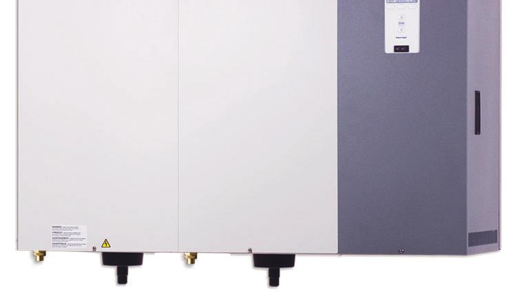
 Fill cup High water sensor Steam cylinder Overflow hose Electrodes Electrical")
6 Product overview PRODUCT OVERVIEW DriSteem XT Series electrode steam humidifiers use heat caused by electrical resistance in their fill water to boil the fill water into humidification steam. Steam output and water conductivity are managed via automatic draining and filling. See Figure 2-1. FIGURE 2-1: XT SERIES HUMIDIFIER COMPONENTS Steam to duct or XT steam blower (see dispersion options on Page 8) Download DriSteem literature DriSteem product manuals can be downloaded, printed, and ordered from our website: The Vapor-logic Installation and Operation Manual ships with Model XTP humidifiers. It is a comprehensive manual. Refer to it for information about the keypad/display and Web interface, and for troubleshooting information. Control panel for on-board controller (see Figure 3-1) Fill cup High water sensor Steam cylinder Overflow hose Electrodes Electrical resistance in fill water OM-7661_aa Cylinder drain Fill hose Supply water connection Overflow to drain Note: See detailed installation drawing on Page 14 and principle of operation on Page 45. 2


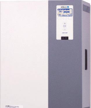
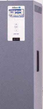
7 Product overview SUPPLY WATER There are benefits and trade-offs to consider when the application allows a choice between hard and softened water: Hard water: The benefit of hard water is less frequent draining and filling than with softened water, which results in better energy and water efficiency and more consistent steam output. However, cylinder replacement could be more frequent with hard water, because hard water scale coats the electrodes. The harder the water, the more frequent the need for a new cylinder. Softened water may be used in the XT series electrode humidifier. However, softened water ions stay in solution to much higher concentrations than hard water ions. The result can be more frequent draining and filling, which results in less energy and water efficiency, and less consistent steam output. While softened water can reduce scale build-up in the cylinder, it can also shorten cylinder electrode life. CONTROLLER The Model XTP humidifier Vapor-logic controller features menus for all humidifier functions, with a Web interface for access to all functions via Ethernet. See "Operations" beginning on page 45 for details. Table 3-1: DriSteem supply water guidelines for XT series electrode humidifiers Supply water conductivity Chlorides 350 to 1250 μs/cm (roughly comparable to water hardness of 10 to 36 grains per gallon). Not limited ph 6.5 to 8.5 Silica < 15 ppm Demineralized, deionized, and reverseosmosis water cannot be used. Supply water outside of these guidelines may void your DriSteem warranty. Please contact your DriSteem Representative or DriSteem Technical Support if you need advice. FIGURE 3-1: XT SERIES HUMIDIFIER CONTROL PANEL Status display and menu selection XTP Vapor-logic keypad/display Softkeys for direct menu access Navigation buttons for item selection Controller on-off switch* * On-off switch for control board not a safety shut-off to humidifier power wiring. 3
8 SPECIFICATIONS Capacities, line currents, and fusing Table 4-1: Line currents and recommended fusing for XT Series humidifiers Model Nominal steam capacity XTP lbs/hr kg/h * * * * * These models have two steam cylinders and require independent service connections. kw Phase Volts Maximum line current (amps) Recommended fusing (amps) x 43 2 x x 36 2 x x 29 2 x x 58 2 x x 48 2 x x 39 2 x x 72 2 x x 60 2 x x 48 2 x x 80 2 x x 69 2 x x 55 2 x 70 4
9 SPECIFICATIONS Dimensional drawings FIGURE 5-1: XT SERIES HUMIDIFIER DIMENSIONAL DRAWINGS Top Models XTP 002 through 048 E Electrical knockout Dispersion outlet D Top Models XTP 050 through 096 E 21.0 (533) Electrical knockout D Front 10.0 (254) Fill cup extension kit* Front 10.0 (254) Dispersion outlets Fill cup extension kits* B B Bottom Drain outlet A Supply water connection Electrical knockouts A C F D OM-7672 Bottom G Supply water connections 15.1 (384) Electrical knockouts G E C OM-7673 Notes: * Fill cup extension (Figure 5-1) is required for the following: - All XT Series humidifiers using Ultra-sorb or Rapid-sorb - When developed length of steam tubing is more than 20' (6 m) and duct static pressure exceeds 2" wc (498 Pa) Labeled dimensions: inches (millimeters). See mounting dimensions in Figure 9-1. F D E 21.0 (533) Drain outlets 5
10 SPECIFICATIONS Dimensions and weights Table 6-1: XT Series humidifier dimensions by model number Dimension Description Model XTP 002, 003, , , 033, 042, , 067, 083, 096 inches mm inches mm inches mm inches mm A Cabinet width B Cabinet height C Cabinet depth D Cabinet back edge to steam/drain outlet centers E Cabinet left edge to steam/drain outlet centers F G Cabinet back edge to supply water connection center Cabinet left edge to supply water connection center Table 6-2: XT Series humidifier weights by model number Model XTP 002, , , 033, 042, , 067, 083, 096 lbs kg lbs kg lbs kg lbs kg lbs kg Shipping weight Maximum operating weight
11 SPECIFICATIONS Dispersion options The duct dispersion options in Figure 7-1 and the open space dispersion options in Figure 7-2 are available for XT Series humidifiers. For installation details, see Dispersion beginning on Page 20. FIGURE 7-2: XT STEAM BLOWERS Mounted on top of humidifier FIGURE 7-1: XT SERIES HUMIDIFIER DUCT DISPERSION OPTIONS Ultra-sorb OM-7670 OM-7667 Mounted up to 10' (3 m) away from humidifier Rapid-sorb OM-7668 OM-7698 Single dispersion tube OM-7669 Notes: Models XTP 010 and larger require condensate drain. See Page 32. XT steam blowers (SDU) shipped with fuses to be installed in connected XT series humidifiers. 7
12 Selecting a location HUMIDIFIER When selecting a location for the humidifier, consider the following: Proximity to the duct Install the humidifier near the air duct system where the dispersion assembly will be located. The maximum recommended length for steam hose connecting a single humidifier to a dispersion assembly is 10' (3 m). The maximum recommended developed length for tubing connecting a single humidifier to a dispersion assembly is 20' (6 m). For more information about installing dispersion assemblies, see Dispersion beginning on Page 20. Elevation of the installed dispersion assembly The recommended installation location for the dispersion assembly is at an elevation higher than the humidifier. However, if the dispersion assembly must be installed at an elevation lower than the humidifier, install a drip tee and drain. See Drip tee installation on Page 29. Staging multiple humidifiers Up to four Model XTP humidifiers can be staged to operate in sequence. In a sequenced application, one control input signal is divided into user-selectable control input signals for the connected humidifiers. See the Vapor-logic In stal la tion and Op er a tion Man u al for instructions on staging multiple humidifiers. FIGURE 8-1: XT SERIES HUMIDIFIER RECOMMENDED MINIMUM CLEARANCES 16" (400 mm) 36" (914 mm) front clearance Before installing a dispersion assembly or interconnecting piping, review all pitch requirements in the Dispersion section of this manual. Temperature and relative humidity (RH): Install humidifier only in locations that meet the following temperature and RH requirements: - Maximum ambient temperature: 104 F (40 C) - Minimum ambient temperature: 41 F (5 C) - Maximum ambient humidity: 80% RH (non-condensing) 3" (76 mm) 15" (380 mm) 3" (76 mm) between units OM-7664 Required clearances (see Figure 8-1) Electrical connections Electrical power supply connections are at the lower or upper right rear corner of the unit. See Humidifier wiring on Pages 17 and 18. Supply water and drain piping connections Water supply piping and drain connections are at the bottom of the cabinet. See Piping on Page 13. Exterior wall insulation Install the humidifier on an exterior wall only if the wall is properly insulated. DISPERSION CONTROL DEVICES See page 20 for recommended installation locations for the dispersion assembly and associated control devices. 8
13 Mounting FIGURE 9-1: XT SERIES HUMIDIFIER MOUNTING KEYHOLE LOCATIONS Models XTP 002 through 048 Models XTP 050 through " x 0.719" (9.9 x 18.3 mm) dia. keyholes A B C 0.390" x 0.719" (9.9 x 18.3 mm) dia. keyholes E A B C D D OM-7969 OM " (9.9 mm) dia. holes 0.390" (9.9 mm) dia. holes Table 9-1: XT Series humidifier mounting keyhole dimensions Dimension Model XTP 002, 003, , , 033, 042, , 067, 083, 096 inches mm inches mm inches mm inches mm A B C D E
14 Mounting Unpack the humidifier from the shipping carton, and remove the cabinet doors and steam cylinder (see removing steam cylinder instructions below). Note: When first unpacking the humidifier, cut and remove the shipping strap that goes around the cylinder and through the cylinder guides. This strap does not need to be replaced. REMOVING STEAM CYLINDER If sent to this page from the Maintenance section, and the humidifier has been operating, make sure the cylinder is empty and cooled before removing it. See the shutdown and cool-down procedures on Page 49. WARNING Mounting hazard Mount humidifier per the instructions in this manual and to a structurally stable surface. Improper mounting of the humidifier can cause it to fall or tip, resulting in severe personal injury or death. 1. Carefully pull the electrode plugs straight up off the cylinder to ensure no damage to the plug boot occurs. 2. Disconnect the high water sensor wire. 3. Place hands palms-down below cylinder on both sides of drain outlet. 4. Press up against bottom of cylinder with backs of hands while pressing down against cabinet floor with fingers. 5. Raise cylinder until drain outlet clears drain valve body and the side tabs on the cylinder have cleared the cylinder guides. Remove cylinder from cabinet. WALL MOUNTING HUMIDIFIER Mount the humidifier level and plumb using the lag bolts provided. Follow the instructions below for mounting on a wood stud wall. 1. Mount spanner boards on wall, spanning at least two studs. Position one board at top of cabinet (for the lag bolts), and other board at bottom of cabinet. 2. Predrill pilot holes in spanner boards, and secure humidifier to spanner boards with lag bolts. Note: Use the appropriate mounting methods and mounting hardware for other wall types. 10
15 Fill cup extension kit A fill cup extension (Figure 11-1) is required for the following: All XT Series humidifiers using Ultra-sorb or Rapid-sorb When developed length of steam tubing is more than 20' (6 m) and duct static pressure exceeds 2" wc (498 Pa) FIGURE 11-1: FILL CUP EXTENSION KIT Fill cup (see inset below) REMOVING EXISTING FILL CUP Remove the existing fill cup as follows: 1. Remove steam cylinder from XT cabinet (if not already out). 2. Expand spring clamps and slide them up cylinder fill hose and supply water hose, and disconnect hoses from cylinder fill hose connection and fill valve adapter. 3. Disconnect overflow hose from overflow elbow. 4. Remove fill cup and hoses (fill cup is press fit into top of XT cabinet). INSTALLING FILL CUP EXTENSION KIT 1. Remove steam cylinder(s) from XT cabinet (if not already out). 2. Route fill cup extension kit hoses into cabinet through fill cup hole, and fasten extension bracket as shown with two screws provided. 3. Route hoses along back of cabinet interior to provide clearance for cylinder. 4. Cut supply water hose (small-diameter hose) (A) to length so it can attach to fill valve adapter without kinking. 5. Expand spring clamp and slide it onto supply water hose (A) far enough so it will not interfere, then push hose onto fill valve adapter. Expand and slide spring clamp into place. 6. Cut cylinder fill hose (bottom, center hose) (B) to length so it can attach to cylinder fill hose connection without kinking. 7. Expand spring clamp and slide it onto cylinder fill hose (B) far enough so it will not interfere, then push hose onto cylinder fill hose connection. Expand and slide spring clamp into place. 8. Cut overflow hose (C) to length so it can attach to overflow elbow without kinking. 9. Push overflow hose onto overflow elbow. Spring clamp is not required on this connection. Overflow hose (C) Supply water hose (A) Fill valve adapter Supply water (A) Cylinder fill (B) Overflow elbow Drain cup plate Cylinder fill hose connection Cylinder fill hose (B) OM-7629 OM-7971-XT Fill cup 1" air gap Overflow (C) 11
16 Steam cylinder INSTALLING STEAM CYLINDER 1. Make sure strainer is pressed into steam cylinder drain outlet and strainer flange is flush with bottom of cylinder outlet. See Figure Use water to lubricate drain outlet on bottom of cylinder and O-ring in drain valve body. See Figure Note: Because of tight clearances, perform Steps 3 through 4 only if servicing Models XTP 002 through 017 with top-mounted steam blower. For all other models, skip to Step Slide steam hose that connects to cylinder and steam blower up until it is engaged on steam inlet of steam blower and tight against bottom of steam blower. 4. Slide steam outlet of new cylinder all the way up into open end of steam hose from Step With Warning label on cylinder facing you, lower cylinder drain outlet into drain valve body, and rotate cylinder so side tabs line up with cylinder guides inside cabinet. Push down on cylinder until drain outlet is fully seated in drain valve body. FIGURE 12-1: STEAM CYLINDER OM-7632 Strainer High water sensor pin 6. Slide steam hose down so it is fully engaged on cylinder steam outlet. Re-install hose clamp(s). 7. Connect high water sensor (yellow) wire to single pin surrounded by plastic shoulder on cylinder. 8. Connect electrode wires to pins on top of cylinder. Make sure all plugs fit snugly and are fully engaged on pins. Important: Three phase cylinders have color-coded dots on the cylinder and color bands on the electrode plugs. When connecting the plugs, match the band colors on the plugs with the dot colors on the cylinder. Refer to the wiring diagram shipped with the humidifier if necessary. Warning label Cylinder guide Drain valve body OM-7972-XT CAUTION If cylinder plugs become loose, damage to the humidifier may occur. Obtain replacement plugs from DriSteem. See Replacement parts on Pages 57 and 59 for part numbers. 12
17 Piping: Supply water and drain SUPPLY WATER PIPING Use only copper for supply water piping; do not use rubber or plastic. The standard supply water connection before the fill valve is a 1/4" FIP. Note: The supply water connection size is 3/8" BSP [DN10] in Europe. In cases where water hammer may be a possibility, consider installing a shock arrestor. Water pressure must be 25 to 80 psi (175 to 550 kpa). DRAIN PIPING Drain piping must be code-approved, 3/4" (DN 20) ID material rated for 212 F (100 C) minimum. The drain cup has an integral grounding plate and requires a field-installed 1" (25 mm) air gap to a drain funnel to prevent conduction of electricity in the drain line. The XT Series humidifier features user-selectable drain water tempering. When drain water tempering is selected, the humidifier tempers drain water by opening the fill valve whenever the drain valve is energized to cool drain water before it enters the drain. Drain water tempering keeps water entering the drain line less than 140 F (60 C). Manually energizing the drain valve when the supply water is shut off can allow 212 F (100 C) water to enter the drain line. Observe the following precautions when selecting and installing drain piping to ensure personal safety and material integrity: When using copper or other metallic drain piping, ground the drain piping to the earth ground lug in the XT Series humidifier. Chlorinated polyvinyl chloride (CPVC) piping is a non-metallic alternative for drain piping. It is rated up to 212 F (100 C) for intermittent-use, lowpressure applications. The connection size for the steam cylinder drain is 1" (DN25) hose. Do not reduce this connection size. If drainage by gravity is not possible, use a reservoir pump rated for 212 F (100 C) water. The open drain must be at least 12 (300 mm) below the bottom of the XT humidifier, to help prevent steam condensation on the humidifier. Use the 12 (300 mm) drain hose provided and position above field-installed open drain. Alternately, route drain line away from beneath humidifier to open drain. See Figure Important: Thoroughly flush supply water piping to remove pipe residue and stagnant water before connecting piping to humidifier. Pipe residue and stagnant water in water supply piping can cause foaming, preventing humidifier from reaching required steam capacity. WARNING Hot drain pipes Drain piping surface may be hot. Touching or contact with hot pipe may cause severe personal injury. FIGURE 13-1: DRAIN PIPING DETAIL 1" (25 mm) air gap Open drain 3/4" (DN20) I.D. OM-7591 Hose clamp* Drain hose* Pitch 1/8"/ft (1%) toward drain To drain * Ships with humidifier Dashed lines indicate provided by installer The open drain must be at least 12 (300 mm) below the bottom of the XT humidifier, to help prevent steam condensation on the humidifier. AUTOMATIC DRAIN WATER TEMPERING XT Series humidifiers are shipped with drain water tempering set to ON for North America (OFF for Europe). To activate automatic drain water tempering see the Vapor-logic Installation and Operation Manual. 13
18 Piping: Field piping overview FIGURE 14-1: XT SERIES HUMIDIFIER FIELD PIPING OVERVIEW Steam hose or tubing. DriSteem recommends tubing for runs longer than 10' (3 m). See Table 26-1 for maximum tubing lengths. Tubing must be grounded. Drain hose and clamp* Fill valve with 1/4" FIP (3/8" BSP [DN10] in Europe) supply water connection Shock arrester (by installer) recommended to reduce water hammer Metallic water supply line Install plumb Pitch 1/8"/ft (1%) toward drain Floor drain 1" (25 mm) air gap required to isolate unit drain piping from sanitary drain piping. Locate air gap only in spaces with adequate temperature and air movement to absorb flash steam, or condensing on nearby surfaces could occur. Open drains required directly below humidifier drains to prevent downstream drain line blockage from causing water to back up into cylinder. Refer to governing codes for drain pipe size and maximum discharge water temperature. Install spill funnels plumb to floor drain. 1¼" (DN32) drain piping after second drain connection, or if piping run is over 10 (3 m). 3/4" (DN20) drain piping up to second drain connection 3/8" (DN10) copper water supply line; water pressure must be 25 to 80 psi (175 to 550 kpa). Inlet strainer, by installer OM-7973 Notes: Dashed lines indicate provided by installer. Two-cylinder model shown. * Ships with humidifier Supply valve, by installer 14
19 Piping: XT steam blowers FIGURE 15-1: PIPING FROM XT SERIES HUMIDIFIER TO REMOTE XT STEAM BLOWER Hose clamp (provided) Steam hose (purchased separately from DriSteem) Hose clamp (provided) Plastic tie Notes: Maximum recommended distance between humidifier and XT steam blower is 10 (3 m). Models XTP 042 through 096 are not intended for use with a steam blower. Condensate hose (purchased separately from DriSteem) 7 (178 mm) water seal OM-7974 Plastic tie To open drain or humidifier fill cup. Water seal is required, whether condensate is piped to open drain or returned to humidifier fill cup. Hose clamps (provided) Steam hose (purchased separately from DriSteem) Stainless steel Y connector* Hose clamp* Steam hose* Plastic tie Condensate hose (purchased separately from DriSteem) Hose clamp* * Provided in optional connector kit Part No OM-7975 Model XTP 025 only Plastic tie 7 (178 mm) water seal To open drain or humidifier fill cup. Water seal is required, whether condensate is piped to open drain or returned to humidifier fill cup. 15
20 Piping: XT steam blowers FIGURE 16-1: PIPING FROM XT SERIES HUMIDIFIER TO TOP-MOUNTED XT STEAM BLOWER Hose clamp (provided) Steam hose (provided) Hose clamp (provided) OM-7976 Notes: Maximum recommended distance between humidifier and XT steam blower is 10 (3 m). Models XTP 025 and 033 are not intended for use with a direct-mounted steam blower. Models XTP 042 through 096 are not intended for use with a steam blower. 16
21 Humidifi er wiring All wiring must be code approved and in accordance with the unit wiring diagram. Power supply wiring must be rated for 105 C. See Figure 17-1 for the humidifier wiring diagram locations. When selecting a location for installing the humidifier: Avoid areas close to sources of electromagnetic emissions such as power distribution transformers. Do not loop power wiring. Do not use aluminum wire. WARNING Electric shock hazard Only qualified electrical personnel should perform field wiring installation procedures. Improper wiring or contact with energized circuits may cause property damage, severe personal injury, or death as a result of electric shock and/or fire. CONDUIT KNOCKOUTS Conduit and control wiring knockouts are provided on the XT Series humidifier cabinet. See Figure 5-1. CONTROL COMPONENT PLACEMENT Follow the guidelines on Page 19 for placing humidistats, transmitters, and airflow proving switches. CAUTION Adding conduit connections not recommended Adding alternate conduit connections is not recommended. If you must make additional holes in the humidifier cabinet, protect all internal components from debris, and vacuum out the cabinet when finished. Failure to follow these precautions can damage sensitive electronic components and void the DriSteem warranty. FIGURE 17-1: FIELD WIRING REQUIREMENTS Wiring diagram inside of humidifier cabinet Fused disconnect Power supply XT Series humidifier OM-7692 Notes: Control wiring and power wiring must be run in dedicated or separate earthed metal conduit, cable trays, or trunking. Separate the line voltage wiring from low voltage control circuit wiring when routing electrical wiring inside the humidifier cabinet. Do not use chassis or safety grounds as current-carrying commons. Never use a safety ground as a conductor or neutral to return circuit current. For circuit protection requirements, see recommended fusing in Table
22 Humidifi er wiring CONNECTION INSTRUCTIONS Before connecting power, refer to the wiring diagram or the data plate on the outside of the cabinet for wire sizing amperage. For control signal wiring from a humidistat, transmitter, or signal by others, see the wiring diagrams shipped inside the humidifier. See Step 1 Field wiring in the Vapor-logic Installation and Operation Manual for detailed instructions on the following: Control input wiring: See the Control input section. Duct airflow proving switch and duct high limit humidistat wiring (recommended optional devices): See the following sections: Airflow proving switch and Duct high limit switch or transmitter Remote signal wiring: See the following sections: Programmable triac and Programmable relay (dry contact) EARTH GROUNDING REQUIREMENTS A code-approved safety earth grounding system is required. The ground connection must be made with solid metal-to-metal connections. Ground wire should be the same size as power wiring. UNITS WITH STEAM BLOWER Steam blowers (SDUs) receive power for operation from the XT series humidifier. Install 2 fuses in the XT unit to provide power to the steam blower. Fuses are shipped with the steam blower. Replacements available from DriSteem. WARNING Excessive moisture hazard DriSteem strongly recommends installing a duct airflow proving switch and a duct high limit humidistat. These devices prevent a humidifier from making steam when there is low airfl ow in the duct or when the RH level in the duct is too high. Failure to install these devices can result in excessive moisture in the duct, which can cause bacteria and mold growth or dripping through the duct. Proper wiring prevents electrical noise. Electrical noise can produce undesirable effects on electronic control circuits, which affects controllability. Electrical noise is generated by electrical equipment, such as: inductive loads, electric motors, solenoid coils, welding machinery, or fluorescent light circuits. The electrical noise or interference generated from these sources (and the effect on controllers) is difficult to define, but the most common symptoms are erratic control or intermittent operational problems. Important: For maximum EMC effectiveness, wire all humidity, high limit, and airflow controls using multicolored shielded/screened plenum-rated cable with a drain wire for the shield/screen. Connect the drain wire to the shield/screen ground terminal with wire less than 2" (50 mm) in length. Do not ground shield at the device end. 18
23 Sensor placement SENSOR LOCATION IS CRITICAL Sensor location has a significant impact on humidifier performance. See the recommendations below and Figure Note: DriSteem recommends that you do not interchange room and duct humidity devices. Room humidity devices are calibrated with zero or little airflow, whereas duct humidity devices require air passing across them. Recommended humidity control (transmitter/humidistat) locations: A. Ideal. Ensures the best uniform mix of dry and moist air with stable temperature control. B. Acceptable, but room environment can affect controllability, such as when sensor is too close to air grilles, registers, or heat radiation from room lighting. C. Acceptable. Provides uniform mixture of dry and moist air. If extended time lag exists between humidity generation and sensing, extend sampling time. D. Acceptable (behind wall or partition) for sampling entire room if sensor is near an air exhaust return outlet. Typical placement for sampling a critical area. E. Not acceptable. These locations might not represent actual overall conditions in the space. F. Not acceptable. Do not place sensors near windows, door passageways, or areas of stagnant airflow. Other factors affecting humidity control Humidity control involves more than the controller s ability to control the system. Other factors that play an important role in overall system control are: Size of humidification system relative to load Overall system dynamics associated with moisture migration time lags Accuracy of humidistats and humidity transmitters and their location Dry bulb temperature accuracy in space or duct Velocities and airflow patterns in ducts and space environments Electrical noise or interference Recommended safety (airflow and high limit) sensor location: G. Best sensing location for high limit humidistat or humidity sensor and airfl ow proving switch. FIGURE 19-1: RECOMMENDED SENSOR LOCATIONS Outside air Damper control Relief air Return air C Air handling unit 8' to 12' (2.4 m to 3.7 m) min. G High limit humidistat or high limit transmitter (set at 90% RH maximum) Airflow switch or differential pressure switch (sail type recommended for VAV applications) A Window E Wall or partition D B E Vapor absorption has taken place Point of vapor absorption Humidifier dispersion assembly Turning vanes F E F DC-1084 mc_060508_0750-xt Doorway Window 19
24 Dispersion: Selecting the dispersion assembly location DriSteem humidifiers operate with several types of dispersion assemblies for open spaces and for ducts and air handling units. Dispersion assemblies in ducts and air handling units must be positioned where the water vapor being discharged is carried off with the airstream and is absorbed before it can cause condensation or dripping. In general, the dispersion assembly is best placed where the air can absorb the moisture being added without causing con den sa tion at or after the unit. This normally will be after the heating coil or where the air tem per a ture is highest. 20
25 Dispersion: Selecting the dispersion assembly location Place the dispersion assembly such that absorption will occur: before the intake of a high efficiency filter, because the filter can remove the visible moisture and become waterlogged; before coming in contact with any metal surface; before fire or smoke detection devices; before a split in the duct; otherwise, the dispersion assembly can direct more moisture into one duct than the other. When draining dispersion condensate to an open drain, provide a 1" (25 mm) air gap between the condensate drain piping and the drain. Locate the gap only in spaces with adequate temperature and air movement to absorb flash steam; otherwise, condensation may form on nearby surfaces. WARNING Hot surface and steam hazard Dispersion assembly and steam hose or tubing can contain steam, and surfaces can be hot. Discharged steam is not visible. Contact with hot surfaces or air into which steam has been discharged can cause severe personal injury. 21
26 Dispersion: Returning condensate to steam cylinder CONDENSATE RETURN GUIDELINES To prevent overfilling the steam cylinder, follow the condensate guidelines below: When condensate can be returned to the steam cylinder: Single dispersion tube Up to 20 lbs/hr (9.1 kg/h) of steam production 10' (3 m) or less of steam hose between humidifier and dispersion 20' (6 m) or less of tubing between humidifier and dispersion When condensate should be wasted to the drain: Ultra-sorb or Rapid-sorb dispersion Single dispersion tube with condensate drain Single dispersion tube with: - More than 20 lbs/hr (9.1 kg/h) or more of steam production, or - More than 10' (3 m) of steam hose between humidifier and dispersion - More than 20' (6 m) of tubing between humidifier and dispersion XT Series humidifier steam outlet The steam outlet on the humidifier is sized to the output of the humidifier. DO NOT use interconnecting steam hose or tubing with an inside diameter smaller than the humidifier steam outlet. Reducing the inside diameter will result in the internal humidifier system pressure exceeding the parameters for acceptable performance. See maximum steam carrying capacities in Table 26-1 and If the humidifier must be located higher than the dispersion assembly, use the recommended installation shown in Figure
27 Dispersion: Steam outlet connections FIGURE 23-1: STEAM OUTLET CONNECTIONS, MODELS XTP 002 THROUGH 025 Models XTP 002 through 006 To dispersion assembly Models XTP 010 through 025 To dispersion assembly Connector (optional)* See Caution below 1½ (DN40) steam hose 1 (DN25) steam hose, 12" (305 mm) long (optional)* Hose clamp (optional)* 1½ (DN40) I.D. steam hose** Hose clamp** OM-7977 OM-7978_aa * Provided in optional connector kit Part No (see Table 61-1) ** Provided by installer. CAUTION Connector kit location Install the connector for increasing from 1 to 1½ (DN25 to DN40) hose or tube immediately above the XT Series humidifier as shown above. Failure to install the connector kit immediately above the humidifier will cause system pressure fluctuations and increase cylinder pressure, steam velocity, and condensate noise. 23
28 Dispersion: Steam outlet connections with hose FIGURE 24-1: STEAM OUTLET CONNECTIONS WITH HOSE, MODELS XTP 033 THROUGH XTP096 WITHIN 10' (3 M) OF DISPERSION ASSEMBLY WARNING Preventing back pressure/abnormal operation in dual cylinder humidifiers and installations where two individual units are connected to a single dispersion panel. Read and follow all steam hose installation instructions. Failure to follow these instructions could result in excessive back pressure or abnormal operation of the unit. Severe personal injury or damage to the unit may result. Models XTP 033, 042, and 048 2" (DN50) steam hose, 10' (3 m) maximum To dispersion assembly Stainless steel Y connector* Hose clamp* 1½" (DN40) steam hose*, 12" (305 mm) long Notes: For horizontal runs longer than 5' (1.5 m) or vertical runs long than 10' (3m), tubing is required. Do not use steam hose. See Table 61-1 for optional kits listed below. * Provided in optional connector kit Part No ** Provided in optional connector kit Part No *** Provided in optional connector kit Part No F Model XTP 050 OM-7979 Models XTP 067 through 096 3" (DN80) flange connection*** attaches directly to dispersion Hose clamp** Stainless steel tube connector** Steam hose** attaches directly to dispersion, 2" (DN50) on Ultra-sorb and Rapid-sorb 1½" (DN40) steam hose. Each cylinder to connect to dispersion separately. For distance greater than 10', use hard pipe. 2" (DN50) steam hose. Each cylinder to connect to dispersion separately. For distance greater than 10', use hard pipe. Stainless steel Y connector* OM-7980-XT Hose clamp* 1½" (DN40) steam hose*, 12" (305 mm) long OM
29 Dispersion: Steam outlet connections with hose FIGURE 25-1: CONNECTING TWO CYLINDERS TO A DISPERSION ASSEMBLY 2" (DN50) steam hose connection 1½" (DN40) hose connections from two cylinders OM-7913 WARNING Preventing back pressure/abnormal operation in dual cylinder humidifiers and installations where two individual units are connected to a single dispersion panel. Read and follow all steam hose installation instructions. Failure to follow these instructions could result in excessive back pressure or abnormal operation of the unit. Severe personal injury or damage to the unit may result. 3" (DN80) flange connection 2" (DN50) hose connections from two cylinders OM-7914 Notes: For two cylinders, connect the stainless steel tube connector directly to the dispersion inlet as shown. The diameter and pitch of the tube connector must match the inlet diameter and pitch of the dispersion unit. Always run separate steam hose/tubing from each cylinder to the connection of the dispersion device. Only connect a maximum of two cylinders to any single dispersion unit. 25
30 Dispersion: Interconnecting piping requirements Condensate control and collection Controlling condensate flow and collection in an XT Series humidifier system is critical to performance. To maximize humidifier performance: See Table and Follow all installation recommendations for your specific humidifier and dispersion assembly from here through Page 44. Table 26-1: Maximum steam carrying capacity and length of interconnecting steam hose and tubing for Models XTP 002 through XTP096 Model Hose I.D. DriSteem steam hose* Maximum capacity per cylinder Maximum length Copper or stainless steel tubing (Insulate tubing to minimize loss of capacity and efficiency.) Tube size Maximum capacity per cylinder Maximum developed length XTP inches DN lbs/hr kg/h ft m inches DN lbs/hr kg/h ft m 002 1½ ½ ½ ½ ½ ½ ½ ½ ½ ½ , 050** 033, 067** 042, 083** 048, 096** 1½ ½ Notes: Values in this table are based on XT Series humidifiers, and condensate flowing in direction of steam (steam hose or tubing pitched toward dispersion device). * Use DriSteem steam hose for best results. Field-supplied hose may have shorter life and may cause foaming in cylinder, resulting in condensate discharge at dispersion assembly. Do not use steam hose for outdoor applications. ** These models have two steam cylinders. Capacities based on use with fill cup extensions. For Models XTP 050 through XTP 096, capacities listed are maximum steam carrying capacity per tube attached to each cylinder, with separate steam tubing from each cylinder to connection on dispersion device. See Figure DriSteem recommends 10' (3 m) maximum steam hose length pitched at 2"/ft (15%). Steam hose can sag if not supported for its full length. Sagging leads to collecting condensate and system pressure issues. Metallic tubing is less prone to sagging and can allow for 1/8"/ft (1%) pitch minimum and longer distances. Developed length of tubing equals measured length plus 50% of measured length, to account for fittings. 26
31 Dispersion: Interconnecting piping requirements CONNECTING TO HUMIDIFIER WITH STEAM HOSE Support steam hose for its full length to prevent sags, or low spots: For single dispersion tube without condensate drain, maintain a minimum pitch of 2"/ft (15%) toward the steam cylinder. For dispersion devices with condensate drain, maintain a minimum pitch of 2"/ft (15%) toward the dispersion device. Use DriSteem steam hose. Other manufacturers of steam hose may use unacceptable release agents or material mixes that can affect humidifier system performance adversely. Using hose from alternative manufacturers increases the possibility of foaming in the cylinder and accelerated steam hose aging. Foaming causes condensate discharge at the dispersion assembly. Do not use steam hose in outdoor applications. Do not insulate steam hose. Insulation causes accelerated heat aging, causing the steam hose to become hard and susceptible to failure due to cracks. For single dispersion tube applications, see hose kit sizes in Table For tubing connections, see "Connecting to humidifier with tubing" on page 28. Important: Steam hose must be supported for its full length to prevent sagging or low spots. Table 27-1: Steam loss of interconnecting steam hose and tubing Description Nominal hose or tubing size Noninsulated Steam loss Insulated Insulation thickness inches DN lbs/hr/ft kg/h/m lbs/hr/ft kg/h/m inches mm Steam hose Tubing 1½ N/A N/A N/A N/A N/A N/A N/A N/A 1½ Note: These data are based on an ambient air temperature of 80 F (27 C), fiberglass insulation, and copper tubing. 27
32 Dispersion: Connecting to humidifier with tubing See Figures 31-1 and 32-1 for interconnecting tubing pitch requirements for single dispersion tube applications. See Table 34-3 for interconnecting tubing pitch requirements for Rapid-sorb applications. Support tubing between the humidifier steam outlet and the dispersion system with pipe hangers. Failure to properly support the entire tubing weight may cause damage to the humidifier tank and void the warranty. Ground metal steam tubing. See Grounding steam tubing at right. 90 elbows are not recommended. DriSteem recommends 90 long sweeps. Two 45 elbows, 1' (0.3 m) apart may also be used. Insulating tubing reduces the loss in output caused by condensation. If flux or any other surface preparation material is used when connecting steam tubing and fittings, drain and fill the steam cylinder two times after the first half hour of steam production: Model XTP, step 5 on page 48 This will minimize the possibility of foaming in the steam cylinder. Important: Failure to follow the recommendations in this section can result in excessive back pressure on the humidifier. This will result in unacceptable humidification system performance such as leaking gaskets, blown water seals, erratic water level control, and spitting condensate from dispersion tubes. Grounding steam tubing The XT Series humidifier has built-in functionality for detecting and eliminating foaming in the steam cylinder. However, because brief periods of foaming are possible, grounding metal steam tubing back to the humidifier earth ground lug is necessary. This earth ground will prevent foam from creating an electrically conductive path from the electrically charged cylinder water to the metal steam tubing. FIGURE 28-1: DETAIL OF VERTICAL RISER DRIPS 90 long sweep or two 45 elbows Pitch To dispersion assembly Insulate tubing to reduce steam loss Pitch Tubing drip tee 6" (150 mm) recommended XT Series humidifier 3/4" (DN20) 1" (25 mm) air gap 8" (200 mm) recommended Open funnel or floor drain OM
33 Dispersion: Drip tee installation Install a drip tee as shown below when the humidifier is mounted higher than the dispersion assembly, when interconnecting hose or tubing needs to go over an obstruction, or when interconnecting piping runs are long. FIGURE 29-1: DRIP TEE 90 long sweep or two 45 elbows Pitch Obstruction Insulate tubing to reduce steam loss XT Series humidifier OM-7695 To dispersion assembly 6" (150 mm) recommended Tubing drip tee, by installer (see Part No. in Table 61-1) 8" (200 mm) minimum 3/4" (DN20) 1" (25 mm) air gap Open funnel or floor drain. See first note below. Notes: Locate air gap only in spaces with adequate temperature and air movement to absorb flash steam; otherwise, condensation may form on nearby surfaces. Refer to governing codes for drain pipe size and maximum discharge water temperature. Support steam hose for its full length so there are no sags or low spots. Dashed lines indicate provided by installer. mc_062810_0645-xt 29
34 Dispersion: Single dispersion tube DISPERSION TUBE WITH OR WITHOUT CONDENSATE DRAIN Use a hose cuff and clamps to connect the steam outlet to tubing. Tubing diameter must match XT steam outlet connection. See maximum steam carrying capacities in Table 26-1 and steam loss in Table If mounting the humidifier above the level of dispersion tube, see "Drip tee installation" on Page 29. See also "Vertical riser drip details" in Figure DISPERSION TUBE WITHOUT CONDENSATE DRAIN, XTP 002 THROUGH 006 See Figure Maximum capacity of 1½" (DN40) dispersion tube without condensate drain is 29 lbs/hr (13.2 kg/h) insulated; 28 lbs/hr (12.7 kg/h) uninsulated. Condensate can flow back to the cylinder against 20 lbs/hr (9.1 kg/h) steam flow. Pitch the steam supply line back toward the humidifier (see Figure 31-1). Important: Failure to follow the recommendations in this section can result in excessive back pressure on the humidifier. This will result in unacceptable humidification system performance such as leaking gaskets, blown water seals, erratic water level control, and spitting condensate from dispersion tubes. CAUTION Connector kit location Install the connector for increasing from 1 to 1½ (DN25 to DN40) hose or tube immediately above the XT Series humidifier as shown in Figure Failure to install the connector kit immediately above the humidifier will cause system pressure fluctuations and increase cylinder pressure, steam velocity, and condensate noise. 30
35 Dispersion: Single dispersion tube FIGURE 31-1: SINGLE DISPERSION TUBE WITHOUT CONDENSATE DRAIN, MODELS XTP 002 THROUGH 006 ONLY Tubing must be grounded. Insulate tubing to reduce steam loss. See Table 26-1 for maximum tubing lengths. See first bullet in installation notes above. Optional connector (see Caution above) Note: Dashed lines indicate provided by installer. Single dispersion tube without condensate drain Pitch* Secure and seal escutcheon plates. 90 long sweep or two 45 elbows Duct Pitch 2"/ft (15%) OM-7693 Dispersion tube escutcheon plate 4.5" (115 mm) minimum from top of duct Mounting nut, 3/8" - 16 (M10) Dispersion tube: Orient with tubelets (steam orifices) pointing up. A * Pitch steam hose or tubing toward humidifier: 2"/ft (15%) when using steam hose ½"/ft (5%) when using 1½" tubing ¼"/ft (2%) when using 2" tubing XT Series humidifier A OM Dimension A: 3.25" (82.5 mm) for 1½" tubes 31
36 Dispersion: Single dispersion tube DISPERSION TUBE WITH CONDENSATE DRAIN, MODELS XTP 010 AND 017 See Figure Maximum capacity of 1½" (DN40) dispersion tube with condensate drain is 65 lbs/hr (29.5 kg/h) insulated; 62 lbs/hr (28.1 kg/h) uninsulated. Models XTP 010 through XTP096 have capacities requiring dispersion devices with condensate drains. DriSteem recommends pitching steam tubing for these models towards the dispersion device. For XT Series humidifiers with capacities more than 20 lbs/ hr (9.1 kg/h), the installer should not attempt to drain condensate back to the cylinder. When a vertical riser is required in the steam tubing, a drip tee is required in order to eliminate a condensate collection point that will restrict steam flow. See vertical riser examples in Figure If maximum developed length is more than 20' (6 m) and duct static pressure exceeds 2" wc (498 Pa), a fill cup extension kit (Figure 11-1) is required. Table 32-1: Hose kit sizing by capacity Hose kit (steam hose, dispersion tube, and hardware) Maximum tube capacity Insulated Uninsulated lbs/hr kg/h lbs/hr kg/h 1½" (DN40) without drain ½" (DN40) with drain These capacities require multiple tube assemblies and cannot use a single hose kit. >65.0 >29.5 >62.0 >28.1 Capacities of Models XTP 025 through XTP096 require multiple tube assemblies and cannot use a hose kit. For multiple tube assemblies, see Rapid-sorb beginning on Page 33. FIGURE 32-1: SINGLE DISPERSION TUBE WITH CONDENSATE DRAIN, MODELS XTP 002 THROUGH 017 ONLY Tubing must be grounded. Insulate tubing to reduce steam loss. See Table 27-1 for maximum tubing lengths. Secure and seal escutcheon plates Duct Single dispersion tube with condensate drain; orient dispersion tube with tubelets (steam orifices) pointing up. Pitch tube toward drain 1/8"/ft (1%). 90 long sweep or two 45 elbows XT Series humidifier 6" (150 mm) recommended Water seal 5" (125 mm) 1" (25 mm) air gap OM-7694 Pitch* 1/4" NPT (DN8) Mounting nut, 3/8" 16 (M10) 4.5" (115 mm) minimum from bottom of duct 1/2" O.D. (DN15) condensate drain tube. Pitch 1/4 /ft (2%) toward escutcheon plate. 3/4" (DN20) (minimum) condensate drain tube by installer. Must be suitable for 212 F (100 C) water. Open drain required. Locate air gap only in spaces with adequate temperature and air movement to absorb flash steam; otherwise, condensation may form on nearby surfaces. Refer to governing codes for drain pipe size and maximum discharge water temperature. * Pitch steam hose or tubing toward humidifier: 2"/ft (15%) when using steam hose 1/8"/ft (1%) when using tubing Dispersion tube Escutcheon plates Condensate drain Note: Dashed lines indicate provided by installer. A A A OM A Dimension A: 3.25" (82.5 mm) for 1½" tubes 32
37 Dispersion: Rapid-sorb Read all dispersion instructions in this manual, and follow the installation instructions below: Unpack shipment and verify receipt of all Rapid-sorb components with packing list. Report any shortages to DriSteem immediately. The components typically include the following: Multiple dispersion tubes Header 3/4" 2" (19 mm 51 mm) L-bracket Note: Dispersion tubes, header, and L-bracket are each tagged with the customer requested identification number. A single duct escutcheon plate the size of the header Slip couplings or hose cuffs and clamps Accessories such as duct plates, slip couplings, or hose cuffs Bolts and washers for mounting the dispersion tubes to the bracket L-bracket mounting holes (see note): L-bracket 50" (1270 mm) long or shorter has a mounting hole 4" (100 mm) from each end for mounting the L-bracket to the duct or air handler wall. L-bracket longer than 50" (1270 mm) has an additional mounting hole in the center. Note: Hardware for mounting the L-bracket to the duct or air handler wall and the hardware for the header support bracket is not provided. Select an installation location that provides necessary access in and around the ductwork or air handler. The Rapid-sorb typically is installed centered side to side in a duct, or is installed across the face of a coil in an air handler. The center line of the outer dispersion tubes should never be closer than 4.5" (114 mm) from the side of the ductwork or air handler wall. The following instructions are for a typical Rapid-sorb installation horizontal-airflow duct with Rapid-sorb header either inside or outside the duct. See the DriCalc Installation Guides library or contact your representative/distributor or DriSteem for installation instructions for air handler or vertical airflow applications. Important: Before marking and drilling holes in the duct or air handler, refer to ALL pitch re quire ments for the Rapid-sorb as sem bly you received (see page 34). The size, quan ti ty, and location of penetrations are determined by the dimensions and configuration of the Rapid-sorb assembly you received. Important: WARNING Hot surface and steam hazard Dispersion assembly and steam hose or tubing can contain steam, and surfaces can be hot. Discharged steam is not visible. Contact with hot surfaces or air into which steam has been discharged can cause severe personal injury. Failure to follow the recommendations in this section can result in excessive back pressure on the humidifier. This will result in unacceptable humidification system performance such as leaking gaskets, blown water seals, erratic water level control, and spitting condensate from dispersion tubes. 33
38 Dispersion: Rapid-sorb PITCH REQUIREMENTS For Rapid-sorb with the header outside a horizontalairflow duct, consider the following: 1½" (DN40) dispersion tubes: Use a fastener of sufficient length to ac com mo date the 1/8"/ft (1%) pitch requirement toward the 3/4" pipe thread (DN20) header drain fitting. 2" (DN50) dispersion tubes: Bracket can be mounted flush to ductwork. Typically, the 1/8"/ft (1%) pitch can be accomplished in the length of the hose cuffs used to connect tubes to header. See Table 34-3 and the drawings on the following pages for pitch requirements. Table 34-1: Rapid-sorb dispersion tube capacities* Tube diameter Tube capacity Insulated (High-Efficiency Tubes) Uninsulated inches DN lbs/hr kg/h lbs/hr kg/h 1½ * Capacities shown are for horizontal airflow. See DriCalc for vertical airflow capacities. If face height is <22" (559 mm), tube quantity per panel may need to increase to compensate for reduced capacity of short tubes. Consult DriSteem or see DriCalc sizing and selection software for the correct calculation. Table 34-2: Rapid-sorb header capacities Header capacity Header diameter lbs/hr kg/h inches DN Table 34-3: Pitch of interconnecting piping, dispersion tubes, and headers for Rapid-sorb evaporative dispersion units Airflow Type of interconnecting piping Diameter of interconnecting piping Pitch of interconnecting piping Pitch of dispersion tubes Pitch of header Horizontal Steam hose Tubing 1½" (DN40) 2" (DN50) 1½" (DN40) 2" (DN50) 2"/ft (15%) toward Rapid-sorb 1/8"/ft (1%) toward Rapid-sorb Vertically plumb 1/8 /ft (1%) toward condensate drain Vertical Steam hose Tubing 1½" (DN40) 2" (DN50) 1½" (DN40) 2" (DN50) 2 /ft (15%) toward Rapid-sorb 2"/ft (15%) 1/8 /ft (1%) toward Rapid-sorb toward header 1/8 /ft (1%) toward condensate drain 34
39 Dispersion: Rapid-sorb with Models XTP 025 through 048 FIGURE 35-1: RAPID-SORB IN A HORIZONTAL AIRFLOW WITH HEADER INSIDE THE DUCT L-bracket. Install with flange facing upstream direction of airflow. Drawing shows L-bracket correctly positioned for airflow. Dispersion tube. Orient with tubelets perpendicular to airflow. 90 long sweep or two 45 elbows Tubing must be grounded. Insulate tubing to reduce steam loss. See Tables 26-1 and 27-1 for maximum tubing lengths. See Notes. XT Series humidifier Slip coupling or hose cuff 2"/ft (15%) when using steam hose ¼"/ft (2%) when using 2" tubing Secure and seal escutcheon plates. Header pitch: 1/8"/ft (1%) minimum OM-7696 Notes: 1. Use a hose cuff and clamps to connect steam outlet to tubing. 2. See installation procedure on Page Dashed lines indicate provided by installer. Duct Airflow Support bracket has 0.421" (11 mm) mounting holes at top, bottom, and end) Condensate drain: 6" (150 mm) 3/4" pipe thread (DN20) recommended 3/4" (DN20) copper 1" (25 mm) air gap 5" (125 mm) recommended Open drain required: Locate air gap only in spaces with adequate temperature and air movement to absorb flash steam; otherwise, condensation may form on nearby surfaces. Refer to governing codes for drain pipe size and maximum discharge water temperature. WARNING Hot surface and steam hazard Dispersion assembly and steam hose or tubing can contain steam, and surfaces can be hot. Discharged steam is not visible. Contact with hot surfaces or air into which steam has been discharged can cause severe personal injury. 35
40 Dispersion: Rapid-sorb and Ultra-sorb with Models XTP 050 through 096 Models XTP 050 through XTP 096 have capacities requiring dispersion devices with condensate drains (Figure 35-1). For these models, DriSteem recommends the following: Run separate steam tubing from each cylinder to the connection on the dispersion device. Pitch steam tubing toward the dispersion device. The installer should not attempt to drain condensate back to the cylinder. When a vertical riser is required in the steam tubing, a drip tee is required in order to eliminate a condensate collection point that will restrict steam flow. FIGURE 36-1: DUAL-CYLINDER XT SERIES HUMIDIFIER CONNECTED TO RAPID-SORB OR ULTRA-SORB WITH RISER DRIPS IN STEAM SUPPLY LINES WARNING Preventing back pressure in dual-cylinder humidifiers Read and follow all steam tubing installation instructions for dual-cylinder humidifiers. Failure to follow these instructions could result in excessive back pressure and the risk of equipment damage or severe personal injury. Pitch* Rapid-sorb steam dispersion panel Pitch* Pitch* Pitch* Drain Drip tee Ultra-sorb steam dispersion panel Drain OM-7982-XT Dual-cylinder XT Series humidifier Drain Notes: * Pitch 1/8"/ft (1%) minimum toward dispersion panel. See installation notes in Figure
41 Dispersion: Rapid-sorb WITH HEADER INSIDE OF DUCT FOR HORIZONTAL AIRFLOW Note: See the instructions for installing Rapid-sorb with the header outside the duct for horizontal airflow. 1. Mark and cut holes in ductwork or air handler for steam header pen e tra tion, con den sate drain piping, and head er support bracket fastener. Allow 1/8"/ft (1%) header pitch toward the support bracket when you drill the hole for the header support bracket fastener. 2. Loosely fasten the header in place. 3. Rotate the header 90 so the header stubs point hor i zon tal ly in the duct. When installing in an air handler, the rotation of the header is often less than 90. Typically, due to the condensate drain piping re quire ments, the header can be set on the floor of the air handler, assembled in the vertical position, and then raised and mounted in place. 4. Mount the dispersion tubes on the header with the slip couplings or hose cuffs: When installing slip couplings for 1½" (DN40) dispersion tubes, take care not to shear O-rings. Set slip coupling on header stub or dis per sion tube so O-ring is resting on face of tubing. Rotate slip coupling while pushing it onto the tubing. O-rings are lubricated at factory. If additional lubrication is necessary, DO NOT use petroleum-based lubricant. 5. Allow the dispersion tubes to rest against the bottom of the duct. CAUTION Operate Rapid-sorb within rated steam capacity Excessive steam flow to the Rapid-sorb steam dispersion assembly can cause condensate to exit the tubelets, which can cause water damage and standing water in the duct or air handler. To avoid condensate exiting the tubelets, do not operate the Rapid-sorb beyond its rated capacity. With header outside of duct for horizontal airflow 1. Mark and cut holes in the ductwork for the dispersion tubes. Use the L-bracket as a template to mark the holes on the duct floor. 2. Temporarily, loosely suspend or support the header below the final location. Vertical balance point of the dispersion tube length dictates where the header should be suspended or temporarily supported. 3. Continue with Step 4 at right. 37
42 Dispersion: Rapid-sorb 6. Position the flange of the L-bracket so it is upstream of the tubes when the assembly is rotated into position. Fasten the L-bracket to the end of the dispersion tubes with the provided bolt, lock washer, and flat washer. 7. Rotate the assembly up until the L-bracket aligns with the mounting holes in the duct or air handler. For 1½" (DN40) dispersion tubes: Header pitch is duplicated in the L-bracket. Dispersion tube and slip coupling must be fully engaged on header stub for O-rings to provide a seal. High end of L-bracket can be fastened tight to duct or air handler. Fastener on low end of L-bracket must be long enough to compensate for pitch. Use a nut on both sides of L-bracket and duct or air handler for stability. 2" (DN50) dispersion tubes Fasten bracket to top of duct and use hose cuffs to compensate for header pitch. Before securing hose cuffs with hose clamps on dispersion tube and header stub, verify that dispersion tube orifices are directed perpendicular to airflow. 8. Verify that all fasteners are secure: L-bracket to duct Dispersion tubes to L-bracket Hose clamps on 2" (DN50) tubes Header support bracket fastener 9. Secure and seal the header escutcheon plate around the header. Note: See Page 39 for steam supply and condensate drain line connection instructions. 38
43 Dispersion: Rapid-sorb STEAM SUPPLY CONNECTIONS TO RAPID-SORB HEADER Connect the steam supply interconnecting piping from the humidifier to the Rapid-sorb. Steam supply piping requires a minimum of 1/8"/ft (1%) pitch toward the header. If two humidifiers are supplying one Rapid-sorb, a steam supply connector is needed. Typically, the steam supply connector attaches to the Rapid-sorb header supply end with hose cuff and clamps: 1. Always run separate steam tubing from each cylinder to the connection on the dispersion device. Connect a maximum of two cylinders to any single dispersion unit. See page 24 for more detailed instructions and connector kit part numbers. 2. Position the steam supply connector to accept the steam supplies while maintaining the necessary pitch. 3. Make sure the hose clamps on the steam supply connector and header are tight. CONDENSATE DRAIN CONNECTIONS TO RAPID-SORB HEADER Piping must be minimum 3/4" I.D. (DN20) and rated for 212 F (100 C) minimum continuous operating temperature. The condensate drain line must be piped as shown in Figure Provide a 6" (150 mm) drop prior to a 5" (125 mm) water seal to: Ensure drainage of condensate from the header Keep steam from blowing out of the drain line After the water seal, run the drain line to an open drain with a 1" (25 mm) vertical air gap. Cut the drain line at a 45 angle on the end above the drain to permit a direct stream of water into the drain pipe while maintaining a 1" (25 mm) air gap. Locate air gap only in spaces with adequate temperature and air movement to absorb flash steam, or condensing on nearby surfaces may occur. All drain lines must be installed and sized according to governing codes. 39
44 Dispersion: XT steam blowers Fuses provided with the steam blowers must first be installed in the associated XT series humidifiers. XT STEAM BLOWER RISE, SPREAD, AND THROW On a call for humidity, the controller closes the contactors to energize the humidifier electrodes and the XT steam Air intake blower. When the call for humidity is satisfied, the Rise controller opens the humidifier contactor, which stops the steam blower. Spread Throw Steam outlet As steam is discharged from the XT steam blower, it quickly cools and turns to a visible fog that is lighter than air. As this fog is carried away from the XT steam blower by the airstream, it tends to rise toward the ceiling. If the fog contacts solid surfaces (columns, beams, ceiling, pipes, etc.) before it disappears, it can condense and drip. The greater the space relative humidity, the further the fog will rise, spread, and throw. Table 40-1 lists the maximum rise, spread, and throw non-wetting distances for XT Series humidifiers with XT steam blowers. Surfaces cooler than ambient temperature, or objects located within this minimum dimension, can cause condensation and dripping. To avoid steam impingement on surrounding areas, observe the minimum non-wetting distances in the table. OM-7686 XT steam blowers are field wired to the XT Series humidifier blower terminals. A wiring diagram is included with the XT steam blower. Table 40-1: XT steam blower minimum non-wetting distances Model Nominal steam capacity 30% 70 ºF (21 ºC) 40% 70 ºF (21 ºC) 50% 70 ºF (21 ºC) 60% 70 ºF (21 ºC) Rise Spread Throw Rise Spread Throw Rise Spread Throw Rise Spread Throw XTP lbs/hr kg/h ft m ft m ft m ft m ft m ft m ft m ft m ft m ft m ft m ft m * * Rise: Minimum non-wetting height above the steam outlet of the XT steam blower Spread: Minimum non-wetting width from the steam outlet of the XT steam blower Throw: Minimum non-wetting horizontal distance from the steam outlet of the XT steam blower * These models use two XT steam blowers. 40
45 Dispersion: XT steam blowers FIGURE 41-1: XT STEAM BLOWER DIMENSIONS SDU-006E shown Front Side Back A C D E The XT steam blower can be mounted on top of an XT Series humidifier cabinet, or wallmounted remotely from the humidifier. See Figure SDU-006E, for capacities up to 20 lbs/hr (9.1 kg/h), can be directly mounted on Models XTP 002 through 006. B OM-7688 F SDU-017E, for capacities up to 50 lbs/hr (22.7 kg/h), can be directly mounted on Models XTP 010 and 017. XT Series humidifiers can be configured to operate with one or two steam blowers. Multiple SDU-017 are used remotely with Model XTP 025 or 033. See Table Note: XT steam blower installation must comply with governing codes. Table 41-1: XT steam blower dimensions Table 41-2: Single or multiple XT steam blowers for XT Series humidifiers* Dimension SDU-006E SDU-017E inches mm inches mm Model XTP SDU-006 per kit SDU-017 per kit A B C D E F through 096 n/a n/a * XT steam blowers are sold as kits to match the associated XT Series humidifier. The number of XT steam blowers per kit are shown in this table. Table 41-3: XT steam blower specifications Model Maximum capacity Shipping weight Operating weight Volume airflow lbs/hr kg/h lbs kg lbs kg cfm m 3 /min Current draw at 115V (50/60 Hz) Input power Noise SDU-006E A 17 W 49 dba SDU-017E A 23 W 53 dba Notes: XT steam blowers ship separately from XT Series humidifiers. Noise measurements taken 6.5' (2 m) in front of XT steam blower cabinet. 41
46 Dispersion: XT steam blowers MOUNTING XT STEAM BLOWER ON TOP OF HUMIDIFIER The condensate tee kit shipped with the XT steam blower returns condensate from a top-mounted XT steam blower to the humidifier's cylinder fill hose. See Figure Install the kit as follows: 1. If humidifier is not already mounted to wall, see Wall mounting humidifier on Page Remove steam cylinder (see Removing steam cylinder on Page 10). 3. Assemble condensate hose from kit to condensate outlet at base of steam box, and install both plastic ties (included) on hose to ensure secure connection to steam box condensate outlet. For remote-mounting the XT steam blower, see Page 43. FIGURE 42-1: CONDENSATE TEE KIT FOR TOP-MOUNTED XT STEAM BLOWER * Supplied with condensate tee kit Steam box Two plastic ties* 4. Assemble hose cuff and clamp to steam port on steam box. 5. Remove middle-rear knockout on top of humidifier cabinet, and mount XT steam blower to wall as noted on Page Feed condensate hose into humidifier cabinet through knockout hole created in Step 5, place XT humidifier below XT steam blower on wall, and secure humidifier to wall. 7. Push small burr of tee into loose end of condensate hose that was fed into cabinet in Step Cut midpoint of 5/8" fill hose that connects center port on fill cup to fill connection on floor of humidifier cabinet. Avoid kinks by leaving slack in fill hose for cylinder installation. 9. Install tee in 5/8" fill hose that was cut in Step Install steam cylinder (see Installing steam cylinder on Page 12). Steam port Condensate hose* Tee* 5/8" fill hose OM-7983-XT FIGURE 42-2: TOP- AND REMOTE-MOUNTED XT STEAM BLOWER Mounted on top of humidifier Condensate returned to steam cylinder fill hose Mounted remotely from humidifier Condensate returned to open drain (condensate can also be returned to humidifier fill cup) One XT Series humidifier with two XT steam blowers OM-7670 OM-7698 OM
47 Dispersion: XT steam blowers REMOTE MOUNTING XT STEAM BLOWER The XT steam blower is constructed with a pitch toward the drain; however, it must be installed level and plumb for proper drainage. See the Warning. WARNING Standing water in XT steam blower Make sure the XT steam blower is installed plumb. If it is not installed plumb, standing water can accumulate, which can: cause bacteria and mold growth, which can cause illness; affect XT steam blower performance; cause 212 F (100 C) water to discharge from the XT steam blower, which can cause severe personal injury. Follow the instructions below for your wall type: Mount the XT steam blower using the lag bolts provided. Follow the instructions below for mounting on a wood stud wall. 1. Mount spanner board on wall, spanning at least two studs, at top of XT steam blower cabinet (for the lag bolts). 2. Predrill pilot holes in spanner board, and secure XT stream blower to spanner board with lag bolts. Note: Use the appropriate mounting methods and mounting hardware for other wall types. See Table 40-1 to determine clearance requirements for your application. Make sure walls, ceilings, and other obstructions are not within the non-wetting dimension, or condensation and dripping could occur (read Page 40). Provide at least 3" (76 mm) of clearance on each side of the XT steam blower for air intake. INSTALLING BASE PLATE The steam blower has a base plate for remote-mounted steam blower applications. The base plate isolates the hot steam box from contact. After the electrical connections are made, assemble the base plate onto the bottom of the steam blower with the screws provided. 43
48 Dispersion: XT steam blowers WIRING XT STEAM BLOWERS Make the following wiring connections between the humidifier and the XT steam blower, and tighten all terminals securely: Fuses provided. See page "XT steam blowers" on page 40. FIGURE 44-1: PIPING CONDENSATE TO HUMIDIFIER FILL CUP Field-installed hole in fill cup cap for remote XT steam blower Connect XT steam blower fan wires to humidifier terminals 32, 33, and GRD. Refer to the external connections diagram shipped with the XT steam blower. PIPING CONDENSATE TO HUMIDIFIER FILL CUP 1. Remove fill cup cap from XT Series humidifier, and drill a 1/2" (13 mm) hole in fill cup cap for SDU-006E and SDU-017E condensate hose as shown in Figure Route XT steam blower condensate hose through hole in fill cup cap, and secure condensate hose in place. Note: Make sure condensate hose has a water seal, as shown in Figure The water seal is required to ensure condensate drainage from the XT steam blower and to keep steam from blowing out of the condensate hose. PIPING CONDENSATE TO DRAIN The XT steam blower condensate hose must be routed as shown in Figure The water seal is required to ensure condensate drainage from the XT steam blower and to keep steam from blowing out of the condensate hose. Approximate cap orientation to front of XT Series humidifier cabinet Drill hole here for XT steam blower condensate hose OM-7636X FIGURE 44-2: PIPING CONDENSATE TO DRAIN SDU-017E shown After the water seal, run the condensate hose to an open drain. Cut the hose at a 45 degree angle on the end above the drain to permit a direct stream of water into the drain while maintaining an air gap. The condensate hose must be installed and sized according to governing codes. ADDITIONAL INSTRUCTIONS See instructions for piping from XT Series humidifier to XT steam blower on pages 15 and 16. Condensate hose Plastic tie 1 (25 mm) air gap OM (178 mm) water seal Spill funnel (plumb to floor drain) Open floor drain. Refer to governing codes for drain pipe size and maximum temperature requirements. Note: Shown with condensate to open drain. Condensate can also be returned to fill cup through field-installed hole in fill cup cap. See Figure
49 OPERATION Principle of operation 1. CONTROLLER RECEIVES A CALL FOR HUMIDITY When the RH level in the humidified space drops below set point, the humidifier controller receives a call for humidity and calculates a corresponding electrical current. The controller closes the contactor, which energizes the electrodes. If there is not enough water in the steam cylinder, the fill valve opens and water enters the steam cylinder. 2. ENERGIZED ELECTRODES BOIL WATER INTO STEAM When the water level in the steam cylinder rises to touch the electrodes, electrical current flows through the water between the electrodes. Electrical resistance in the water causes the water to heat up and boil into steam. The steam flows through the steam outlet and through steam hose or tubing to the XT steam blower or dispersion assembly, where it is discharged into the airstream. 3. ELECTRICAL CURRENT INCREASES TO MEET DEMAND As the amount of water covering the electrodes increases, current flow increases. The fill valve remains open until the amperage increases to 10 percent above the current corresponding to the demand signal. Then the fill valve closes, and the water boils into steam. 4. WATER CONTINUES TO BOIL INTO STEAM As the water boils into steam, the amount of water covering the electrodes decreases, and current flow decreases. When current flow decreases to 10 percent below the current corresponding to the demand signal, the fill valve opens to increase the water level in the steam cylinder, which increases current flow and steam production. 5. CONTROLLER INITIATES DRAIN/FILL CYCLES TO FLUSH CONDUCTIVE IONS As steam production continues, the concentration of conductive ions in the water increases, eventually leading to increased electrical current through the water. An algorithm monitors water conductivity and auto tunes drain and fill cycles to keep electrical current within demand parameters. This optimizes humidifier performance based on water conditions and steam production. The humidifier has user-selectable drain water tempering. When drain water tempering is selected, drain water is automatically cooled before entering the drain. WATER CONDUCTIVITY In electrode humidifiers, steam output is directly related to the resistance of the water in the steam cylinder and, therefore, the conductivity of the water between the electrodes. Higher water levels cover more electrode surface and result in more steam; lower water levels cover less electrode surface and result in less steam. Since water conductivity and water level both correlate to steam output, DriSteem s algorithm monitors conductivity and manages drain and fill cycles to optimize humidifier performance and provide proper steam output. DRAIN AND FILL CYCLES As the water in the cylinder boils into steam, the concentration of conductive ions increases until it reaches a threshold that triggers a drain and fill cycle. This rids the cylinder of highly conductive water and replaces it with less conductive fill water. The more conductive the fill water and the higher the demand, the more quickly the threshold is reached, and the more frequently the cylinder automatically drains and fills to stay within the parameters for proper steam output. 45


50 OPERATION Principle of operation FIGURE 46-1: XT SERIES HUMIDIFIER PRINCIPLE OF OPERATION 4 SAFETY FUNCTIONS XT Series humidifiers are protected against running dry current does not flow if the electrodes in the steam cylinder are not submerged in water. If the current rating exceeds 120% of nominal current, the drain valve opens automatically. As the water level drops, the current rating drops back to the nominal value. 1 If the current rating exceeds 120% of the nominal current after several drainage operations, the humidifier shuts down automatically (drain) 5 (supply water connection) Overflow OM-7661X 46
READ AND SAVE THESE INSTRUCTIONS XT SERIES. Electrode Steam Humidifiers. Installation, Operation, and Maintenance Manual
 READ AND SAVE THESE INSTRUCTIONS XT SERIES Electrode Steam Humidifiers Installation, Operation, and Maintenance Manual Warnings and cautions WARNINGS AND CAUTIONS WARNING Indicates a hazardous situation
READ AND SAVE THESE INSTRUCTIONS XTR. Electrode Steam Humidifier. Installation, Operation, and Maintenance Manual
 READ AND SAVE THESE INSTRUCTIONS XTR Electrode Steam Humidifier Installation, Operation, and Maintenance Manual Warnings and cautions WARNINGS AND CAUTIONS WARNING Indicates a hazardous situation that
XT SERIES. Electrode Steam Humidifiers. Easy to maintain Adaptable Comprehensive control with Vapor-logic option
 XT SERIES Electrode Steam Humidifiers Easy to maintain Adaptable Comprehensive control with Vapor-logic option Cost-effective steam humidification Model XTP XT Series electrode steam humidifiers from DriSteem
XT SERIES. Electrode Steam Humidifiers. Easy to maintain Adaptable Comprehensive control with Vapor-logic option
 XT SERIES Electrode Steam Humidifiers Easy to maintain Adaptable Comprehensive control with Vapor-logic option Cost-effective steam humidification XT Series electrode steam humidifiers from DriSteem provide
READ AND SAVE THESE INSTRUCTIONS VAPORMIST. Electric-to-Steam Humidifier. Installation, Operation, and Maintenance Manual
 READ AND SAVE THESE INSTRUCTIONS VAPORMIST Electric-to-Steam Humidifier Installation, Operation, and Maintenance Manual WARNINGS AND CAUTIONS Warnings and cautions WARNING Indicates a hazardous situation
READ AND SAVE THESE INSTRUCTIONS HUMIDI-TECH. Electric Humidifier. Installation, Operation, and Maintenance Manual
 READ AND SAVE THESE INSTRUCTIONS HUMIDI-TECH Electric Humidifier Installation, Operation, and Maintenance Manual WARNINGS AND CAUTIONS Warnings and cautions WARNING Indicates a hazardous situation that
XT Series Electrode Steam Humidifier. Installation, Operation, and Maintenance Manual
 XT Series Electrode Steam Humidifier Installation, Operation, and Maintenance Manual ATTENTION INSTALLER Read this manual before installing humidifier. Leave manual with product owner. DRI-STEEM technical
Vapormist Electric Humidifier. Installation, Operation and Maintenance Manual
 Vapormist Electric Humidifier Installation, Operation and Maintenance Manual ATTENTION INSTALLER Read this manual before installing. Leave manual with product owner. DRI-STEEM technical support 800-328-4447
CRUV. Electric Humidifier. Installation, Operation, and Maintenance Manual
 CRUV Electric Humidifier Installation, Operation, and Maintenance Manual ATTENTION INSTALLER Read this manual before installing. Leave manual with product owner. DRI-STEEM technical support 800-328-4447
XTR Electrode Steam Humidifier. Installation, Operation, and Maintenance Manual
 XTR Electrode Steam Humidifier Installation, Operation, and Maintenance Manual Safety precautions ATTENTION INSTALLER Read this manual before installing humidifier. Leave manual with product owner. DRI-STEEM
READ AND SAVE THESE INSTRUCTIONS LOW-MAINTENANCE HUMIDIFIER. Installation, Operation, and Maintenance Manual
 READ AND SAVE THESE INSTRUCTIONS LOW-MAINTENANCE HUMIDIFIER Installation, Operation, and Maintenance Manual Warnings and Cautions WARNING Indicates a hazardous situation that could result in death or serious
Steam Humidifier Models 1150 and 1160
 Humidifier Steam Humidifier Models 1150 and 1160 Installation, Operation, and Maintenance Manual READ AND SAVE THESE INSTRUCTIONS TABLE OF CONTENTS PRODUCT OVERVIEW.............................. 3 Materials
Ultra-sorb Models LV and LH
 Ultra-sorb Models LV and LH Steam Dispersion Panels Installation, Operation, and Maintenance Manual For applications using steam from a boiler or from any DRI-STEEM steam generating humidifier. Overview
XTR Electrode Steam Humidifier. Installation, Operation, and Maintenance Manual
 XTR Electrode Steam Humidifier Installation, Operation, and Maintenance Manual ATTENTION INSTALLER Read this manual before installing humidifier. Leave manual with product owner. DRI-STEEM technical support
STS Steam-to-Steam Humidifier
 IMPORTANT: Read and save these instructions. STS Steam-to-Steam Humidifier Installation, Operation, and Maintenance Manual Warnings and cautions WARNING Indicates a hazardous situation that could result
Vaporstream Electric Humidifier. Installation, Operation and Maintenance Manual
 Vaporstream Electric Humidifier Installation, Operation and Maintenance Manual ATTENTION INSTALLER Read this manual before installing. Leave manual with product owner. DRI-STEEM technical support 800-328-4447
LTS Liquid-to-Steam Humidifier. Installation, Operation and Maintenance Manual
 LTS Liquid-to-Steam Humidifier Installation, Operation and Maintenance Manual Overview LTS models....3 Dimensions....4 Output capacities....6 Weights, connections and heated water properties.... 7 Installation
Vaporstream Electric Humidifier. Installation, Operation, and Maintenance Manual
 Vaporstream Electric Humidifier Installation, Operation, and Maintenance Manual Warnings and cautions WARNING Indicates a hazardous situation that could result in death or serious injury if instructions
READ AND SAVE THESE INSTRUCTIONS STS. Steam-to-Steam Humidifier. Installation, Operation, and Maintenance Manual
 READ AND SAVE THESE INSTRUCTIONS STS Steam-to-Steam Humidifier Installation, Operation, and Maintenance Manual WARNINGS AND CAUTIONS Warnings and cautions WARNING Indicates a hazardous situation that could
Steam Injection Humidifiers for use with steam boilers. Installation, Operation, and Maintenance Manual
 Steam Injection Humidifiers for use with steam boilers Installation, Operation, and Maintenance Manual ATTENTION INSTALLER Read this manual before installing. Leave manual with product owner. Where to
Residential Steam Humidifier
 Residential Steam Humidifier Model HUMXXSTM3034 Residential Steam Humidifier Owner s Manual Includes Safety & Operating Instructions READ AND SAVE THESE INSTRUCTIONS TABLE OF CONTENTS Safety... 2 Introduction...
Steam Humidification Light Commercial Applications. Better technology means better business.
 Steam Humidification Light Commercial Applications Better technology means better business. Aprilaire Steam Humidifiers are built to last. Through extensive research and over 50 years expertise in humidification
Steam Injection Pressurized Steam Humidifiers. Installation, Operation, and Maintenance Manual
 Steam Injection Pressurized Steam Humidifiers Installation, Operation, and Maintenance Manual Safety precautions ATTENTION INSTALLER Read this manual before installing. Leave manual with product owner.
THE SIX STEPS OF HUMIDIFICATION DESIGN
 THE SIX STEPS OF HUMIDIFICATION DESIGN To help you better understand the humidification process, this issue of Engineering Humidification will walk you through the basic steps of humidification system
Steam Injection Pressurized Steam Humidifiers. Installation, Operation, and Maintenance Manual
 Steam Injection Pressurized Steam Humidifiers Installation, Operation, and Maintenance Manual ATTENTION INSTALLER Read this manual before installing. Leave manual with product owner. DRI-STEEM technical
Ultra-sorb Steam Dispersion Panels
 Ultra-sorb Steam Dispersion Panels PR0DUCT CATALOG Ultra-sorb Model LH Ultra-sorb Model LV Ultra-sorb Model XV DRI-STEEM takes the lead again with Ultra-sorb, establishing the industry standard for energy
VAPORSTREAM. Electric-to-Steam Humidifier. With Vapor-logic controller Web-enabled access Interoperability via Modbus or optional BACnet or LonTalk
 VAPORSTREAM Electric-to-Steam Humidifier With Vapor-logic controller Web-enabled access Interoperability via Modbus or optional BACnet or LonTalk High-performance humidification APPLICATION VERSATILITY
"ER" Series Electric Humidifier
 ER-1 Standard Water "ER" Series Electric Humidifier The Electric Humidifier from PURE Humidifier Co. is loaded with features and options. All you need is tap water, electricity, and a sanitary drain the
ES Series Electric Humidifier
 Read and Save These Instructions Standard Water ES Series Electric Humidifier Installation Instructions Operation and Maintenance Manual ETL LISTED HUMIDIFIER Our results are comforting Form No: ESOM-08-08
INSTY-PAC EXTERNAL MOUNT MULTIPLE TUBE ASSEMBLY
 Read and Save These Instructions Sheet No. EMIP INSTY-PAC EXTERNAL MOUNT MULTIPLE TUBE ASSEMBLY INSTALLATION AND ASSEMBLY INSTRUCTIONS Fig. 1 Tube support AHU/duct Injection tube Typ. centers Flexible
CUFFED FAST-PAC EXTERNAL MOUNT MULTIPLE TUBE ASSEMBLY
 TM READ AND SAVE THESE INSTRUCTIONS CUFFED FAST-PAC EXTERNAL MOUNT MULTIPLE TUBE ASSEMBLY INSTALLATION AND ASSEMBLY INSTRUCTIONS Fig. 1 Flex connectors (by PURE) AHU/duct casing Injection tube Stainless
DRI-STEEM MODEL STS and STS- DI
 DRI-STEEM MODEL STS and STS- DI STEAM-TO-STEAM HUMIDIFIERS Installation, Operation, For toll-free technical support call 1-800-328-4447 TABLE OF CONTENTS To the purchaser and the installer and Maintenance
GTS. Installation, Operation, and Maintenance Manual WARNING. Gas-to-Steam Humidifier
 READ AND SAVE THESE INSTRUCTIONS GTS Gas-to-Steam Humidifier Installation, Operation, and Maintenance Manual WARNING Fire or explosion hazard If the information in this manual is not followed exactly,
Product Data. HUM Humidifiers. FEATURES/BENEFITS (Bypass & Fan Powered Models) FAN POWERED MODELS BYPASS MODELS STEAM MODEL
 FAN POWERED MODELS BYPASS MODELS STEAM MODEL") HUM Humidifiers Product Data HUMXXLFP1518 FAN POWERED MODELS BYPASS MODELS HUMXXSFP1012 HUMBBLBP2417 HUMBBSBP2412 HUMBBWBP2417 (water saver) STEAM MODEL HUMXXSTM3034 Controlling indoor humidity is very
HUM Humidifiers Product Data HUMXXLFP1518 FAN POWERED MODELS BYPASS MODELS HUMXXSFP1012 HUMBBLBP2417 HUMBBSBP2412 HUMBBWBP2417 (water saver) STEAM MODEL HUMXXSTM3034 Controlling indoor humidity is very
Quick Start Installation Guide
 Quick Start Installation Guide Nortec EL Electrode Steam Humidifier Overview Mounting Installation Requirements Standard Mounting Steam Distribution Installation Requirements Plumbing Water and Drainage
GTS Gas-to-Steam Humidifier
 IMPORTANT: Read and save these instructions. GTS Gas-to-Steam Humidifier Installation, Operation, and Maintenance Manual WARNING! If the information in this manual is not followed exactly, a fire or explosion
ULTRA-SORB. Installation, Operation, and Maintenance Manual MODEL. Steam Dispersion Panels
 READ AND SAVE THESE INSTRUCTIONS ULTRA-SORB MODEL MP Steam Dispersion Panels Installation, Operation, and Maintenance Manual For applications using steam from a boiler or from any DriSteem steam generating
ULTRA-SORB. Installation, Operation, and Maintenance Manual MODEL. Steam Dispersion Panel. For pressurized steam applications
 READ AND SAVE THESE INSTRUCTIONS ULTRA-SORB MODEL XV Steam Dispersion Panel Installation, Operation, and Maintenance Manual For pressurized steam applications Table of contents MECHANICAL SPECIFICATIONS..................................................1
Steam Injection Humidifiers for use with steam boilers PR0DUCT CATALOG
 Steam Injection Humidifiers for use with steam boilers PR0DUCT CATALOG Suitable for a wide range of applications Steam Injection humidifiers from DRI-STEEM use steam from an external source, such as an
Steam Injection Humidifiers for use with steam boilers PRODUCT CATALOG
 Steam Injection Humidifiers for use with steam boilers PRODUCT CATALOG Suitable for a wide range of applications Steam Injection humidifiers from DRI-STEEM use steam from an external source, such as an
DRI-STEEM Models and LTS-DI
 READ AND SAVE THESE INSTRUCTIONS DRI-STEEM Models LTS and LTS-DI LIQUID-TO-STEAM HUMIDIFIERS Installation Instructions and Maintenance Operations Manual For Toll-Free Technical Support, Call: 1-800-328-4447
INSTALLATION, OPERATION AND MAINTENANCE MANUAL
 ELECTRONICALLY CONTROLLED STEAM HUMlDlFlERS DESIGN SERIES C & D INSTALLATION, OPERATION AND MAINTENANCE MANUAL CARNES COMPANY, P.O. Box 930040,446 S. Main St., Verona, WI. 53593-1499 - Phone: 608/845-6411
DRI-STEEM Models LTS and LTS-DI
 READ AND SAVE THESE INSTRUCTIONS DRI-STEEM Models LTS and LTS-DI LIQUID-TO-STEAM HUMIDIFIERS Installation Instructions and Maintenance Operations Manual For Toll-Free Technical Support, Call: 1-800-328-4447
Steam Humidifier Fan Pack Installation & Maintenance Instructions
 850 Steam Humidifier Fan Pack 5658 Fan Pack Service Part Steam Humidifier Fan Pack Installation & Maintenance Instructions TABLE OF CONTENTS Safety Cautions...2 Materials List...3 Operation...3 Specifications
Ultra-sorb Steam Dispersion Tube Humidifier Panel
 Ultra-sorb Steam Dispersion Tube Humidifier Panel Installation, Operation, and Maintenance Manual For applications using steam from a boiler or from any DRI-STEEM steam generating humidifier. Table of
SPECIFICATION DIVISION 23 SECTION DESCRIPTION DIVISION 23 HEATING, VENTILATING AND AIR CONDITIONING (HVAC) SECTION STEAM HUMIDIFIERS
 SECTION STEAM HUMIDIFIERS") ARCHITECTURE, ENGINEERING AND CONSTRUCTION P00000000 0000 DOCUMENTS ARCHITECTURE & ENGINEERING 326 East Hoover, Mail Stop B Ann Arbor, MI 48109-1002 Phone: 734-764-3414 Fax: 734-936-3334 SPECIFICATION
ARCHITECTURE, ENGINEERING AND CONSTRUCTION P00000000 0000 DOCUMENTS ARCHITECTURE & ENGINEERING 326 East Hoover, Mail Stop B Ann Arbor, MI 48109-1002 Phone: 734-764-3414 Fax: 734-936-3334 SPECIFICATION
Installation Instructions. Operation and Maintenance Manual
 TM READ AND SAVE THESE INSTRUCTIONS Deionized, Demineralized, or Reverse Osmosis Water SXDDR Series Steam Heat Exchanger Humidifier Installation Instructions Operation and Maintenance Manual Our results
HIGH-PRESSURE ATOMIZING SYSTEM. Humidification and adiabatic cooling. Energy efficient Reduces cooling load Multiple zone capabilities
 HIGH-PRESSURE ATOMIZING SYSTEM Humidification and adiabatic cooling Energy efficient Reduces cooling load Multiple zone capabilities Preliminary 02071 Advanced, efficient humidification PURE PRESSURIZED
GTS Gas-to-Steam Humidifier
 IMPORTANT: Read and save these instructions. GTS Gas-to-Steam Humidifier Installation, Operation, and Maintenance Manual WARNING! If the information in this manual is not followed exactly, a fire or explosion
Installation Instructions. Operation and Maintenance Manual
 READ AND SAVE THESE INSTRUCTIONS Standard Water SX Series Steam Heat Exchanger Humidifier Installation Instructions Operation and Maintenance Manual Our results are comforting PURE HUMIDIFIER and INTAC
CELDEK Evaporative Cooler Module Installation, Operation, and Maintenance Manual. CELDEK Evaporative Cooler
 CELDEK Evaporative Cooler Module Installation, Operation, and Maintenance Manual CELDEK Evaporative Cooler RECEIVING AND INSPECTION Upon receiving unit, check for any interior and exterior damage, and
READ AND SAVE THESE INSTRUCTIONS SEISMIC. Cer tification Option. Installation Manual
 READ AND SAVE THESE INSTRUCTIONS SEISMIC Cer tification Option Installation Manual Warnings and cautions Indicates a hazardous situation that could result in death or serious injury if instructions are
Installation and Maintenance
 Bulletin 527-H Installation and Maintenance Series EHU-700 Humidifiers Please Read And Save These Instructions The Armstrong Series EHU-700 humidifier is an electronically controlled, non-pressurized steam-generating
"ESDDR" Series Electric Humidifier
 ESDDR-1 Deionized, Demineralized, or Reverse Osmosis Water "ESDDR" Series Electric Humidifier The Electric Humidifier from PURE Humidifier Co. is loaded with features and options. All you need is deionized,
L A signature series TA T N E RE O, A L L A T S IN
 signature series COMMERCIAL STEAM GENERATORS INSTALLATION, OPERATION AND MAINTENANCE MANUAL INSTALLATION MANUAL COMMERCIAL STEAM GENERATOR SIGNATURE SERIES (SS) INTRODUCTION Steam Sauna manufactures steam
RV Products Division INSTALLATION INSTRUCTIONS FOR SERIES PACKAGE AIR CONDITIONER
 RV Products Division INSTALLATION INSTRUCTIONS FOR 46413 SERIES PACKAGE AIR CONDITIONER 1. WARNINGS IMPORTANT NOTICE These instructions are for the use of qualified individuals specially trained and experienced
ULTRA-SORB STEAM DISPERSION TUBE HUMIDIFIER PANEL
 READ AND SAVE THESE INSTRUCTIONS This manual must be left with the owner and should be accessible for reference. ULTRA-SORB STEAM DISPERSION TUBE HUMIDIFIER PANEL For Applications Using Steam From A Boiler
GTS. User Manual. Gas-to-Steam Humidifier. Affix product label here.
 Following installation of this steam-generating humidifier, the installer shall instruct the user in the operation of the steam-generating humidifier and the safety devices. The installer shall give at
VAPORSTREAM Models VLC and VLDI
 READ AND SAVE THESE INSTRUCTIONS VAPORSTREAM Models VLC and VLDI ELECTRIC STEAM HUMIDIFIERS Installation Instructions and Maintenance Operations Manual For Toll-Free Customer Support, Call 1-800-328-4447
XTR. Electrode Steam Humidifier
 XTR Electrode Steam Humidifier Easy to operate E asy to maintain just replace the cylinder Affordable to buy, economical to operate D isperse steam into ductwork or open spaces Humidify for health and
FAN POWERED VAV TERMINALS
 FAN POWERED VAV TERMINALS Models VFR, CFR and CFRQ INSTALLATION, OPERATION AND MAINTENANCE MANUAL All data herein is subject to change without notice. Refer to www.enviro-tec.com for current catalog data
Standard and CELDEK Evaporative Cooler Modules Installation, Operation, and Maintenance Manual
 Standard and CELDEK Evaporative Cooler Modules Installation, Operation, and Maintenance Manual Standard Evaporative Cooler CELDEK Evaporative Cooler RECEIVING AND INSPECTION Upon receiving unit, check
EVAPORATIVE COOLING AND HUMIDIFICATION. High-Pressure System Wetted Media System
 EVAPORATIVE COOLING AND HUMIDIFICATION High-Pressure System Wetted Media System Energy efficient Provides both direct and indirect evaporative cooling Multiple zone capabilities in air handlers, ducts,
Standard and CELDEK Evaporative Cooler Modules Installation, Operation, and Maintenance Manual
 Standard and CELDEK Evaporative Cooler Modules Installation, Operation, and Maintenance Manual Standard Evaporative Cooler CELDEK Evaporative Cooler RECEIVING AND INSPECTION Upon receiving unit, check
Installation Instructions. Operation and Maintenance Manual
 Read and Save These Instructions Deionized, Demineralized, or Reverse Osmosis Water ECDDR Series Electric Humidifier Installation Instructions Operation and Maintenance Manual Our results are comforting
EVAPORATIVE COOLING AND HUMIDIFICATION. High-Pressure System Wetted Media System
 EVAPORATIVE COOLING AND HUMIDIFICATION High-Pressure System Wetted Media System Energy efficient Provides both direct and indirect evaporative cooling Multiple zone capabilities in air handlers, ducts,
Humidifiers Dealer Parts List Model 400/400M Humidifiers
 Effective Date: September 1, 2012 Humidifiers Dealer Parts List Model 400/400M Humidifiers MODEL 400 MODEL 400M NO. BLUE/GRAY UNITS - PART NAME QTY/CTN PART NO. PART NO. 4B Base (blue/gray) 1 4734 4734
rev3 INSTALLATION & OPERATION MANUAL OIL CIRCULATING HEATING SYSTEM MODEL OSM
 216279-000 rev3 INSTALLATION & OPERATION MANUAL OIL CIRCULATING HEATING SYSTEM MODEL OSM IDENTIFYING YOUR SYSTEM IOM216279-000 The HOTSTART heating system is designed to heat fluids for use in marine
TYPICAL INSTALLATION Figure A. Condensate Return Line. Humidifier Cabinet. Drain Line
 READ AND SAVE THESE INSTRUCTIONS MODEL HRAA TECHNICAL MANUAL INSTALLATION, OPERATION AND MAINTENANCE INSTRUCTIONS CARNES COMPANY, 448 S. Main St., P. O. Box 930040, Verona, WI 53593-0040 - Phone: 608/845-6411
Installation. 324 Series Built-In Dishwashers U L. Viking Range, LLC 111 Front Street Greenwood, Mississippi USA (662)
") Installation Viking Range, LLC Front Street Greenwood, Mississippi 890 USA (66) 455-00 For product information, call -888-845-464 or visit the Viking Website at vikingrange.com U L C U L 4 Series Built-In
Installation Viking Range, LLC Front Street Greenwood, Mississippi 890 USA (66) 455-00 For product information, call -888-845-464 or visit the Viking Website at vikingrange.com U L C U L 4 Series Built-In
TABLE OF CONTENTS. NOTE: Read the entire instruction manual before starting the installation. TROUBLESHOOTING... 13
 R 410A Duct Free Split System Air Conditioner and Heat Pump Product Family: DFS4(A/H) System, DFC4(A/H)3 Outdoor, DFF4(A/H)H Indoor NOTE: Read the entire instruction manual before starting the installation.
Humidifiers Dealer Parts List
 Effective Date: July, 204 Revised Date: March 20, 205 Humidifiers Dealer Parts List Model 400/400M Humidifiers 6A 6B MODEL 400 MODEL 400M NO. BLUE/GRAY UNITS - PART NAME QTY/CTN PART NO. PART NO. 4B Base
CAREL heatersteam Electric Element Steam Humidifiers
 Suggested Engineering Specifications Section 23 84 13 CAREL heatersteam Electric Element Steam Humidifiers 1. GENERAL SCOPE 1. Furnish and install as indicated on the drawings and plans, in-duct [space]
Installation Electric Dryers Instructions 01
 Installation Electric Dryers Instructions 01 Questions? Call 800.GE.CARES (800.432.2737) or visit our Web site at: GEAppliances.com This is the safety alert symbol. This symbol alerts you to potential
Vapor-logic3 Humidifier Control System
 Vapor-logic3 Humidifier Control System Installation and Operation Manual from the Humidification Experts Table of contents Overview Product overview...1 Summary of features...2 Control input signals...3
Internet Version for Reference Only INDUCED DRAFT COMMERCIAL WATER HEATERS SUPPLEMENT INSTRUCTIONS TO PART #
 INDUCED DRAFT COMMERCIAL WATER HEATERS SUPPLEMENT INSTRUCTIONS TO PART #238-39387-00 THIS INSTRUCTION SUPPLEMENT IS ONLY INTENDED TO GIVE INSTALLATION INSTRUCTIONS AND INFORMATION RELATED TO THE INDUCED
HumidiClean. Series HC- 4100/4145/4300/4500 Humidifiers. Installation, Operation and Maintenance Instructions. Table of Contents.
 Bulletin 537-G HumidiClean Series HC- 4100/4145/4300/4500 Humidifiers Installation, Operation and Maintenance Instructions Table of Contents Page Installation 2-9 Start-Up Procedure and Operation 10-11
INSTALLATION MANUAL. Gas-fired Steam Humidifier Nortec GS. IMPORTANT! Read and save these instructions. This manual to be left with the equipment.
 2583703_EN_1608 IMPORTANT! Read and save these instructions. This manual to be left with the equipment. INSTALLATION MANUAL Gas-fired Steam Humidifier Nortec GS Humidification and Evaporative Cooling DANGER!
Service Bulletin: TrueSTEAM Installation Best Practices Remote Installation Plumbing and Draining Water Quality
 1 Service Bulletin: TrueSTEAM Installation Best Practices Remote Installation Plumbing and Draining Water Quality Remote Installation BEST PRACTICE #1 Length Mount the humidifier as close as possible to
Steam Injection. Humidification system
 Steam Injection Humidification system Standard and CLEAN-STEEM TM models suitable for a wide range of applications DRI-STEEM s Steam Injection humidifiers use steam from an external source, such as an
INSTALLATION INSTRUCTIONS
 INSTALLATION INSTRUCTIONS TM DishDrawer dishwasher DD36SDFTX (Designer) & DD36STI (Integrated) models US CA 59008D 04.3 a SAFETY AND WARNINGS Electrical hazard WARNING! Before installing the dishwasher,
HM700A1000 ELECTRODE STEAM HUMIDIFIER
 ELECTRODE STEAM HUMIDIFIER Tools Needed INSTALLATION INSTRUCTIONS Screwdriver Wrench Pliers Shut-off water valve Water line (LDPE or Copper) Humidifier Configuration The HM700 is configured at the factory
Duct Heaters volts/1 phase volts/3 phase volts/3 phases volts/3 phases. Flange Type Duct Heater.
 Duct Heaters Synheat duct heaters come in various sizes and dimensions to fit any compartment. There are three types of duct heaters available: open coil, tubular element or finned tubular heating elements
VT Series. Service Kit Manual CAUTION
 VT Series Electric Humidifier Service Kit Manual WARNING Indicates a hazardous situation that could result in death or serious injury if instructions are not followed. CAUTION Indicates a hazardous situation
LE Series. Electrode Steam Humidifiers
 LE Series Electrode Steam Humidifiers Electrode Steam Humidifiers The Company For over 35 years, Vapac has been designing, manufacturing and specializing in high quality solutions for indoor air humidification
KINGS COUNTY JAIL EXPANSION PHASE III COUNTY OF KINGS SECTION
 SECTION 237433, PART 1 - GENERAL 1.1 RELATED DOCUMENTS A. Drawings and general provisions of the Contract, including General and Supplementary Conditions and Division 01 Specification Sections, apply to
SKR series Steam Humidifier Kit N (Patent Pending)
") SKR series Steam Humidifier Kit N (Patent Pending) Installation instructions & user manual READ AND SAVE THESE INSTRUCTIONS SKR-N-eng-170608 Foreword Foreword Neptronic Company Overview Founded in 1976,
SKR series Steam Humidifier Kit N (Patent Pending) Installation instructions & user manual READ AND SAVE THESE INSTRUCTIONS SKR-N-eng-170608 Foreword Foreword Neptronic Company Overview Founded in 1976,
DRI-STEEM CRU SERIES ELECTRIC STEAM HUMIDIFIERS
 READ AND SAVE THESE INSTRUCTIONS DRI-STEEM CRU SERIES ELECTRIC STEAM HUMIDIFIERS Installation Instructions and Maintenance Operations Manual For Toll-Free Customer Support, Call: 1-800-328-4447 UL RECOGNIZED
Viking Installation Guide
 Viking Installation Guide Viking Range Corporation 111 Front Street Greenwood, Mississippi 38930 USA (662) 455-1200 For product information, call 1-888-VIKING1 (845-4641) or visit the Viking Web site at
DS 2001 REVISED Humidifier Assembly and Instruction Manual
 DS 2001 REVISED Humidifier Assembly and Instruction Manual Contents Parts list Selecting a location Assembly Hanging the Basin Electrical connections Water connections 2 4 4 Installing the Disk Wheel Installing
Installation, Operation, Maintenance and Troubleshooting Guide
 RESDELUX Steam Humidifiers Installation, Operation, Maintenance and Troubleshooting Guide IMPORTANT: READ AND SAVE THESE INSTRUCTIONS. This guide to be left with equipment owner. Form 03-58 1505691 REV.
FCI500/600/FVI500/FCL/FVL600/FCQ-700 Installation and Maintenance Manual
 FCI500/600/FVI500/FCL/FVL600/FCQ-700 Installation and Maintenance Manual FAN POWERED TERMINALS Receiving Inspection Prior to removing the shipping material, visually inspect the packing materials. There
Installation and Maintenance Manual IM 1102
 Installation and Maintenance Manual IM 1102 Parallel Fan Powered Variable Air Volume (VAV) Terminal Box Group: Applied Air Systems Part Number: IM 1102 Date: October 2010 Model MQFVI5 Table of Contents
Installation instructions for Plenum-mounted add-on electric heaters
 Installation instructions for Plenum-mounted add-on electric heaters Aug. 2008 Version 4 THESE INSTALLATION INSTRUCTIONS COVER: MODEL T-4 to T-30 (4 Kw to 30 Kw) GENERAL NOTES - Please refer to CSA Standard
INSTALLATION INSTRUCTIONS
 INSTALLATION INSTRUCTIONS TM DishDrawer dishwasher DD90SDF(H)TX, DD90SDFTM (Designer) & DD90S(H)TI (Integrated) models NZ AU GB IE 5900D 04.3 FOLLOW THE INSTALLATION SEQUENCE RELEVANT TO YOUR MODEL Designer
Owner s Manual CMC100 Dehumidifier
 Owner s Manual CMC100 Dehumidifier DRI-EAZ PRODUCTS, INC. 15180 Josh Wilson Road, Burlington, WA 98233 Phone: 800-932-3030 Fax: (360) 757-7950 http://cmc-100.dri-eaz.com The CMC100 automatically controls
OPERATING AND MAINTENANCE MANUAL FOR ELECTRIC STAINLESS STEEL HEATER FOR DEIONIZED (DI) WATER ELECTRIC HEATER COMPANY BASE MODEL D
 WATER ELECTRIC HEATER COMPANY BASE MODEL D") OPERATING AND MAINTENANCE MANUAL FOR ELECTRIC STAINLESS STEEL HEATER FOR DEIONIZED (DI) WATER ELECTRIC HEATER COMPANY BASE MODEL D HUBBELL ELECTRIC HEATER COMPANY P.O. BOX 288 STRATFORD, CT 06615 PHONE:
OPERATING AND MAINTENANCE MANUAL FOR ELECTRIC STAINLESS STEEL HEATER FOR DEIONIZED (DI) WATER ELECTRIC HEATER COMPANY BASE MODEL D HUBBELL ELECTRIC HEATER COMPANY P.O. BOX 288 STRATFORD, CT 06615 PHONE:
READ AND SAVE THESE INSTRUCTIONS VAPOR-LOGIC VERSION. Humidifier Control System. Installation. n Operation Manual
 READ AND SAVE THESE INSTRUCTIONS VAPOR-LOGIC V VERSION Humidifier Control System H In Installation n and Operation Manual O 6 Table of contents DriSteem Technical Support 800-328-4447 WARNINGS AND CAUTIONS..................................................
Installation and Operation Guide
 SGH Steam Generating Humidifier Installation and Operation Guide IMPORTANT: Read and save this guide for future reference. This guide to be left with equipment owner. SL-14050 Form # 99-428 Rev. 1 / 150-1633
INSTALLATION, OPERATING & MAINTENANCE INSTRUCTIONS FOR 350 SERIES CIRCULATION HEATERS
 INDEECO Circulation Heaters are designed to provide years of trouble free operation if properly installed and maintained. Please read and follow these instructions for installing and maintaining the heater.