NIBCO Radiant Panel Model RHP-2-4
|
|
|
- Stewart Gilbert
- 5 years ago
- Views:
Transcription

1 NIBCO Radiant Panel Model RHP-2-4 1
2 Table of Contents Cover Page 1 Table of Contents 2 Warning Symbols 3 Safety Warnings 4 Definitions 5 Introduction 6 Specifications and Restrictions 7 Panel Picture with Parts Legend 8 RHP Schematics 9 Installation Instructions Control Sequence 13 Component Descriptions 14 Specifications 15 Pump Instructions TMV Instructions General Terms and Warranty 25 2
3 Warning! Safety First - Always! The following symbols are used throughout this document. For your safety please pay attention. Treated Water, Do Not Drink When used with a boiler, fluid in panel is typical of fluids found in boilers. Not for human consumption or for washing, cleaning or as a dilution fluid. Warning Pay Attention, Health Hazard Do Not Take Risks Possible Dangers If In Doubt, Contact NIBCO INC. Danger Live Power 24 Volt and 110 Volt Qualified Electrician Only Do Not Touch Do Not Touch Hot Pipes, Corrosive Liquids Scalding is Possible Corrosive High or Low ph Do not store corrosives near this panel Danger Explosion Electrical sparks could cause explosion. Do not operate near flammable substances such as, but not limited to: Gas, Oils, Propane, Solvents, Paints, etc. NIBCO shall not be responsible for errors in catalogs, brochures or printed materials. NIBCO reserves the right to alter its products at any time without notice. All trademarks are property of the respective companies. NIBCO PEX is a trademark of NIBCO INC. All Rights Reserved. 3
4 Safety First - Always! Warning! This product must be installed, used, stored and operated strictly in accordance with the terms set out in this manual and in accordance with all laws, rules, codes and regulations of the jurisdiction wherein the product is located. Failure to follow the terms set out in this manual, or the foregoing laws, rules, codes or regulations may result in property damage, serious injury or death. In the event this product is not installed by a qualified person, as defined herein, or in the event this product is not installed, used, stored or operated in accordance with the terms set out in this manual or in accordance with all laws, rules, codes or regulations of the jurisdiction wherein the product is located, or in the event this product is repaired or altered without the written consent of NIBCO, any and all warranties offered by NIBCO in relation to this product will be void, and NIBCO will not be responsible for any direct or indirect damage to this product or to any other property, personal injury, and/or death, regardless of whether NIBCO advised of the possibility of such damage, injury or death. WARNING SYMBOLS: This panel contains electrical devices which could ignite flammable vapors. Do not connect power to, nor operate this equipment in the presence of flammable vapors. The heated fluid supplied to this panel could be hot enough to cause personal injury should skin remain in contact with pipes. Do not mount this panel in any area or manner which could lead to injury. Treat like any other boiler room equipment. Keep children away. The power to be connected to this panel has dangerous capabilities with potential to cause fatal injury. The capability to injure continues to exist whether the power is on or off. No persons should attempt to connect, service, repair or alter this equipment. Only a competent electrician, qualified by local jurisdictions having authority should connect power to the panel. It is the responsibility of the person installing this equipment to provide proper grounding. Improper handling and installation of this product may cause equipment failure, serious injury or death. Follow this manual, National Electrical and Plumbing Codes and Local Codes. Motors and valves mounted on this panel require continuous air circulation. Overheated equipment will lead to premature failure. This panel does not come with pressure control equipment such as a pressure relief valve or expansion tank. This panel is only to be connected to a heating plant which contains safety devices. Do not use petroleum based products in or on this panel. Damage to seals can occur resulting in personal and/or property damage. This product is not protected from freezing. In applications where freeze protection is required, use antifreeze solutions suitable for hydronic systems such as 50/50 mixture of propylene glycol and water. Installing contractor to meet all local environmental and plumbing codes governing backflow prevention. With Glycol, use a stabilized type, a separate stabilizer, or change fluids annually to avoid a buildup of corrosive glycolic acid. See note on Page 7. Brass products such as the valves supplied with this product are adversely affected by media that contain - or that during the process of treatment could develop, agents aggressive to brass. This could include Ammonia, Mercury, Oxygen, Carbon Dioxide, and Chloride. Further, the ph-value of the fluid in the hydronic heating system in contact with the brass products should not exceed 9.5. Neglecting the above restrictions may in some circumstances cause damage to the brass in the panel allowing the heating fluid to escape, possibly causing damage to property and/or persons. 4
5 Definitions ASTM ASHRAE BTU Btuh American Society for Testing and Materials American Society of Heating, Refrigeration and Air-Conditioning Engineers British thermal unit. A unit of measuring the amount of energy required to raise one pound of water by 1 F. British thermal unit per hour. The rate at which energy is transferred. Circuit CSA Design Temperature Heat Source Pipe that is connected from supply manifold to the return manifold. Canadian Standards Assosiation The temperature of the system needed to be maintained under extreme outside temperature conditions. A source of heated fluid for the RHP. This could be electric, gas, or wood-fired heat from a boiler or water heater. Loop RFH RHP Thermostatic Control Thermostatic UL USgpm Zone Single piece of PEX pipe connected to a manifold. Radiant Floor Heating NIBCO PEX Radiant Systems Heat Panel Model RHP An internal mechanical element which reacts to temperature changes. Non electrical temperature control Underwriter s Laboratory Gallons (US) per minute of liquid flow. Area with one or more loops controlled by single thermostat. 5
6 Introduction Introduction Thank you for purchasing a NIBCO (RHP 2-4). The RHP unit is the easiest way to link a properly sized heat source to the radiant system using time tested control technology. Backed by years of experience designing components for the heating industry, the NIBCO RHP is a reliable choice for radiant system control. Features/Benefits Features: Pre-engineered Pre-assembled Pre-wired Compact Modular Warranty Benefits: Designed for Dependable Performance using Proven Components Tested for Installation Leak Free Consistency. Facilitates Quick Trouble Free Start Ups. Minimal area needed for installation. Systems of any size can be assembled. 12 months from purchase. Capacity The RHP-2-4 model will serve up to ten loops. Each loop is capable of handling no more than 0.5 USgpm. Each loop is to be ½ PEX (or BARRIER-PEX). Each loop is not to exceed 250 ft. Function The RHP moves heated fluid to the Radiant Floor Heating (RFH) system and allow you to raise or lower the room temperature. As long as the circulator is moving water according to instructions from the thermostat, the RHP is operating as intended. Performance The delivery of heat to your floor and room is based on the temperature of the fluid, the capacity of the RHP circulator and design of the RFH. Restriction to water flow such as the radiant floor heating pipes in your floor, temperature of the heated water, and the design/installation of your RFH system will have an impact on the system. Most RFH systems need a minimum of 110 o F water to work properly, while some need temperatures of 150 o F. The proper design of a RFH system will make the difference between your satisfaction or dissatisfaction. Several factors such as slab insulation, tube length, spacing, floor covering and heat loss will affect the performance of your system. The RHP has no control over these important factors. Expectations The RHP simply moves the heated water to the RFH(s) based on instructions from the thermostat. There is no need to modify, cut, change, or otherwise alter the RHP. Doing so will void warranty. Disclaimer NIBCO shall not be responsible for any errors in catalogs, brochures or printed materials. NIBCO reserves the right to alter its products at any time without notice. NIBCO is a trademark of NIBCO INC. All Rights Reserved. 6
7 Specifications & Restrictions Circulators The NIBCO RHP is pre-assembled and pre-wired using our standard products. The circulator has been selected to handle the flow requirements for a typical system plus a marginal allowance for any additional pressure capacity not considered. The circulator will be undersized if there are more than 10 loops, if the loops are longer than 250 ft. or if they are smaller than 1/2 in diameter. Hydraulics Pressure losses have been dimensioned based on design flows through ½ nominal PEX tubing at a rate of 0.5 to 0.7 USgpm. A nominal 9 ft. of head for the radiant tubing and 4 ft. of head for control valves, pipe and fittings has been allowed for in the circulator selection. If system requires a larger circulator, you should consider a modular approach and use multiple RHP s. Mixing valves have been selected to provide sufficient flow for a minimum and maximum case. Control Format The RHP utilizes an electronic thermostat, which is placed within the room where temperature is monitored by an internal room sensor. Boiler vs. Domestic Water Heaters Any heat source such as a domestic water heater, cast iron boiler, outside wood furnace or other heat source is compatible with this RHP. NOTE: The circulators supplied with the RHP are suitable for potable applications. If any type of glycol is used in the system, it must be isolated from domestic water use. Propylene glycol is posionous and ethylene glycol is toxic. Follow codes and standards of authorities having jurisdiction. With Glycol, use a stabilized glycol, a separate stabilizer, or change fluids annually to avoid a buildup of corrosive glycolic acid. Manifold Connections The RHP-2-4 is designed for 1 PEX piping to and from the heat source and to and from the distribution manifold. Material Properties of Components The parts used on the RHP are composed of non-ferous material. The types of materials used that are in contact with water are brass, TP 304/TP 304L stainless steel, and EPDM rubber. 7

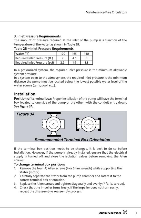
8 NIBCO Radiant Panel - Model RHP-2-4 Parts Legend : 1. Thermostat * 2. Pump 3. Power Box with transformer, relay and integral timer 4. Temperature Gauge 5. Mixing Valve 6. Actuator connections 7. Thermostat connections 8. Auxiliary boiler contacts 9. Zone Valve * 10. Actuator * * Sold separatedly in kit form Supply to Floor <<< <<< Supply from Heat Source 3 Return from Floor >>> >>> Return to Heat Source This is a representative panel. Your model may differ slightly Room Temperature Control The room thermostat(s) (sold separately on the RHP-2-4 model) is the controller that signals the circulator and has an internal air sensor which monitors the temperature. 8
9 RHP Schematic #1 Model Shown: RHP-2-4 Description: Shown with 2 Zones (each with 4 loops), Closed system. This is a representative water heater. Location of supply and return lines may vary. PEX Pipe PEX Pipe 9


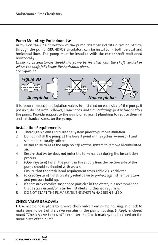
10 Installation Instructions 1. Unpacking Examine carton for visible damage that may have occured during shipping. If damage is visible notify your courier and supplier immediately. Open carton carefully, pull tape off carton, do not cut tape or you may damage the finish on the panel. Remove the panel from the carton, lift panel by base, and do not lift by circulator or other components. Locate and verify that the items shown below are packaged in the carton or in the panel. Before discarding carton, check carefully for any loose components or accessories that may be located in the box. 2. Location of Panel It is recommended the piping distance between the RHP and the heater should be no greater than 20ft. and central to RFH manifolds. In addition, the components on the RHP must be easily accessible should repair or service be required. Give careful consideration to the mounting location of your RHP panel. You must ensure you have adequate room to connect the heat source supply and return as well as the system supply and return to the panel. To minimize piping, locate the panel as close as possible to the heat source (max. 20 ft.). The electrical feed into the panel is through a 6 foot factory wired cord and plug that requires a dedicated 15-amp receptacle. Locate the panel near the receptacle or in an area where such a receptacle can be easily installed. 3. Distribution Pipe Dimension lines are to a pipe velocity between 2 and 5 ft/s. (see chart below). The circulator supplied with the RHP has differential pressure available for some limited distribution piping. Exceeding the available differential pressure could cause under-performance. Please refer to specification sheet or contact NIBCO. 10
11 Installation Instructions Pipe Connections Use 1 PEX or 1 copper to connect from the RHP-2-4 panel to the manifolds and from the panel to the heat source (page 9). Panel connections consist of a union nut, washer, and a FPT adapter. These components must be used on every installation. System connections will consist of a 1 MPT x PEX adapter or 1 MPT x copper adapter, depending on the material used. Follow these steps and refer to picture below. Step 1 Step 2 Step 3 Step 4 Screw 1 FIP adapter (D)(supplied with panel) into adapter (E) or (H) using appropriate thread sealant. Without disturbing gasket (C) place assembly against flanged steel pipe (A) Slide nut (B) over adapter (D) and finger tighten. Use 2, 30mm or adjustable wrenches. Attach 1 to adapter (D) and hold it firmly in place. Attach other wrench to union nut (B) and tighten 1/4 turn. A - Flanged pipe on panel B - Nut on panel C - Rubber gasket D - 1 FIP adapter E - PEX x Male thread adapter F - Copper crimp ring (SS clamp or SS sleeve) G - PEX 11
12 Installation Instructions If you are employing a closed system, i.e. the fluid remains in the system indefinitely, it is required to install an in-line expansion tank in the supply from heat source. This allows for contraction and expansion of the fluid. If your system is open to a municipal water supply and no backflow preventer is in use, an expansion tank is unnecessary. 7. Fill and Purge Running the circulator dry voids warranty. Ensure the system is filled before operating the circulator. The objective in filling the RHP and related equipment is to purge air from the piping network. To allow proper filling and purging, it is necessary to install fill and purge valves as seen in the example schematic on page 9. The fill and purge valves are not included with the RHP. Allow sufficient time and flow for air bubbles to be flushed from the system. An air eliminator (not included) will facilitate the final purging of air. The RHP has no ability to deal with air locks, which impede the performance of the system and can cause the pump to fail. Installer will need two hoses to complete the following procedure. Hoses must each have a female connection to attach to appropriate valves. Washing machine hoses may be employed. (Installer takes responsibility and liability to meet all local environmental codes for discharging fluids). Purging Instructions 1. Turn off power to RHP and fill heat source with fluid. Open all isolation and drain valves (except the one between the fill and purge valves). Manually close all Zone Valves except one. This Zone will be the first to be filled and purged. 2. Close all individual loop isolation (balancing) valves on the selected zone except one. Connect hose to water source outlet and the other end to fill valve. Connect another hose to purge valve and to a suitable discharge (such as a large bucket) and begin filling. Flow will be in reverse of normal. 3. When flow appears free of air bubbles, close the open loop and move to the next loop - thus filling and purging each loop in turn. When finished with one zone, close that Zone Valve and open another Zone Valve. Thus you will fill and purge each zone one at a time. 4. When you have completed all zones, open all Zone Valves. Note: If using a glycol mix, pump in the mix from a large container and purge back into the same container. If using a submersable pump, ensure it has sufficient head to properly fill and purge the system. 8. Wiring Locate room thermostats. Using a suitable thermostat wire of 3 conductors or more, connect to the A, B & 3 terminals on each thermostat. Be sure to note which color wire you used for each terminal and run the wires back to the RHP. Connect the corresponding wires to the connector on the RHP power box labelled Thermostat Connections. The room thermostat should be located in an area representative of the most commonly used space, between 50 and 60 inches above the floor, away from doors, curtains, draughts, direct sunlight, air registers, fireplaces, or any other form of heat which may influence the control. Connect each actuator to the appropriate zone valve by removing the gray cap on the zone valve. Push the actuator down fully on the zone valve, tighten the allen type screw, then remove the red ring from the actuator. Wire the Actuators to the RHP in a similar manner as the thermostats except connect to the section labelled Actuator Connections. Note: There is a small connector on top of the Power Box which provides auxiliary contacts. This pair may be connected to a boiler and the circuit will close when heat is called for by the panel. Finally, connect 110V power to RHP. 9. Pipe Insulation To reduce heat transfer from RHP to room, insulate with standard grade pipe insulation. Do not insulate electric motors. 12
13 Control Sequence Control Notes The RHP does not control the heat source (however see note about auxilary contact on bottom of page 12) The heat source requires its own control system, according to local codes independent of the RHP. Control Sequence Field Setting of the Mixing Valve 1. When room thermostat calls for heat the dry contacts in the thermostat are closed. 2. The radiant circulator will begin to pump heated fluid to the system. 3. The appropriate Zone Valve is opened by the Actuator allowing water to flow to the corresponding zone. 4. When the room temperature is met, the dry contact opens which turns the radiant circulator off. The Zone Valve also closes. Multiple Zone Valves may be opened at any time. The Thermostatic Mixing Valve ( TMV ) mixes hot water from the heat source and return water from the floor. This enables tempering of the hot water supplied to the floor and the return water going back to the heat source. This is particularly important when utilizing a boiler or with a wooden floor. Please consult your boiler manufacturer or installer to determine the correct return water temperature for your heat source. The TMV has six settings which are changed by turning the black knob on top of the TMV. 6 means completely open. In order to adjust the TMV to the proper setting, determine the supply temperature to the RHP and the desired return temperature. Subtract 50 from the return temperature and divide by 10. Add this number to the return temperature to determine the target temperature on the chart below: An example: Your supply temperature is 140 degrees F and your target return temperature is 120 degrees F. (120-50) / 10 = 7 and = 127. Referring to the chart yields a TMV dial setting of 5. Timer Start Up The integral timer s purpose is to circulate water for a short period each day within the system. If you are employing an open system (sharing the heat source with domestic uses) this prevents any stale water from accumulating in the pipes during the summer period. The timer will activate the system for 15 minutes every 24 hours. You should leave the panel turned on with the thermostat turned down even in the summer to allow the timer to activate this circulation. If you are operating a closed system, you may turn the panel off in summer or even disconnect the power cord. 1. Set thermostats 5 to 10 degrees above actual room temperature. 2. If you are using the auxulary contacts to bring on the heat source, make sure they are connected. 3. Plug power cord into a 110V outlet. 4. Observe panel to ensure it follows the proper sequence of operation. 5. After the system temperature stabilizes, verify mixed fluid temperature is within a few degrees of the desired set point by checking on the temperature gauge. If the temperature is off, re-adjust the 3 way thermostatic mixing valve. 13


14 Thermostat Type: RET-24U PX10311 Description/Function: The RET thermostat is designed to be flush mounted and has no floor sensor. Specifications: Temperature range o F 24V AC, 50/60Hz Dry Contact, Max 3A Fully electronic LED status indicator 1 Mixing Valve Type: TMV Model: 065B8999CA PX10292 Description/Function: The TMV (Thermostatic Mixing Valve) is a 3-way brass valve which regulates the temperature in the radiant system. 5 Specifications: Maximum flow temperature 180 F 1 BSPP Maximum working pressure 145 psi Zone Valve and Actuator Type: TWA-A RA Model: 088H Description/Function: Thermal Wax Actuator, normally closed, 24V AC or DC. Connections are 1/2 MPT on one end, 1/2 Swivel FPT on other end. Includes visual position indicator. Specifications: Frequency 50-60HZ Power consumption 2W Spindle travel time +/- 3 minutes Operating temperature 0-60 degrees C Connection is 1/2 MPT and 1/2 FPT swivel 14
15 Specifications Electrical Specifications 6 Amp Inductive Load Transformer 110 Volt Circulators Volumes Weights (RHP-1) Dry: 16lbs (7kg) Filled: 21lb (9kg) Thermal Output to Room (RHP-1) 136 F AWT 205 F AWT 280 F AWT Flow Velocity Materials in Contact with Water Control Valves** TMV: Brass body. Ball Valves Hose bib/ Pet cock: Brass body, PTFE, FKM, EPDM rubber seals Circulator Standard Models Grundfos: PES composite,composite Pump Housing, EP Rubber Piping TP304/TP304L Stainless Maximum Ambient Temperature Maximum Operating Pressure Maximum Operating Temperature 180 F 125 psi 180 F 15
16 16
17 17
18 18
19 19
20 20
21 21
22 22
23 23
24 24
25 Limited Warranty NIBCO PEX - RADIANT HEAT PANELS 1. Confirmation of Purchase NIBCO shall not be deemed to have sold this product unless written proof of purchase is provided. Proof of purchase documents are subject to confirmation by NIBCO. This warranty is limited to the original purchaser of the product. 2. Risk From the moment of purchase the purchaser shall bear all risks for the goods, and NIBCO shall not be responsible for loss and damage incurred during transportation and installation. 3. Information The information and technical data contained in catalogues, leaflets and other written material constitutes an approximate guide only. No responsibility for errors or wrong interpretation can be placed on NIBCO. The purchaser cannot claim any rights based on this material. Such reservation shall also apply to suggestions, advice and other services rendered to customers, including installation and servicing instruction for the product delivered. 4. Alterations NIBCO reserves the right to make alterations to their products without notice. 5. Warranty THE FOLLOWING REMEDY DESCRIBED IN THIS SECTION SHALL BE THE EXCLUSIVE REMEDY FOR ANY BREACH OF THIS WARRANTY. Provided that proof of purchase is provided, the original purchaser is offered a warranty of 12 months on components for from the date of purchase. The warranty covers faulty manufacture, design and/or defective materials. The warranty shall cease to be valid if the product is repaired or altered without the consent of NIBCO, applied for purposes for which it is not designed or installed and applied contrary to the instructions given by NIBCO. NIBCO agrees under the warranty to repair or replace at the discretion of NIBCO such products, which on examination by NIBCO are found to be defective. NIBCO shall not pay expenses in connection with dismantling and mounting. If defects occur while under warranty, the product shall be forwarded to NIBCO at the address noted [below/above], insurance and freight paid. A description of the reason for returning the product shall be enclosed. Products returned shall be free of extraneous equipment. Products repaired under warranty will be returned to the purchaser, freight paid by NIBCO. Parts that have been replaced shall be the property of NIBCO. Guarantee for products not of NIBCO s own manufacture is only given to the same extent as given to NIBCO, however, not exceeding the normal NIBCO warranty. THIS WARRANTY IS IN LIEU OF ALL OTHER WARRANTIES, WHETHER ORAL, WRITTEN, EXPRESS, IMPLIED OR STATUTORY, INCLUDING BUT NOT LIMITED TO ANY WARRANTY OF MERCHANTABILITY OR FITNESS FOR A PARTICULAR PURPOSE, AND OF ANY OTHER OBLIGATION ON THE PART OF NIBCO. NIBCO makes no warranty or representation that the product complies with the requirements of federal, state, and local laws and/or industrial codes, or any other warranty or representation, express or implied, except as specified herein. Any and all representations or warranties by NIBCO or any other party that differ in any manner from the terms of this written Warranty shall be of no force or effect. 6. Secondary Damages NIBCO shall not be held responsible for any OTHER DAMAGES OF ANY KIND, INCLUD- ING incidental or consequential damage e.g. damages to person or property, consequential loss, including loss of production, loss of profit, loss on goods in store or the like, which might arise out of defects and/or delay in delivery of the products sold, irrespective of the cause, including faulty manufacture, design of material. 7. Notice of Claims Any claim or complaint as to defects and / or delay in delivery of the products shall be submitted in writing by the purchaser to NIBCO immediately. 8. Disputes Any disputes or differences arising between the parties hereto shall be resolved according to the law of the State of Indiana. NIBCO reserves the right to decide whether any dispute or difference between the parties hereto shall be referred to binding arbitration or be resolved by legal action. In the event of an election to resolve the dispute or difference by legal action, such action shall take place in the Courts of Indiana having competent jurisdiction. Special Notice to Consumers If you have purchased this product for personal, family or household use: (1) Some states do not permit disclaimers or term limitations of implied warranties so the disclaimers and imitations in this Warranty may not apply to you; (2) Some states do not permit the exclusion or limitation of incidental or consequential damages so the exclusions and limitations in this Warranty may not apply to you; and (3)This Warranty gives you specific legal rights and you may have other rights that vary from State to State. NIBCO INC. Technical Services 1516 Middlebury St. Elkhart, IN
NIBCO Radiant Panel Model RHP-3
 NIBCO Radiant Panel Model RHP-3 1 Table of Contents Cover Page 1 Table of Contents 2 Warning Symbols 3 Safety Warnings 4 Definitions 5 Introduction 6 Specifications and Restrictions 7 Panel Picture with
Basic Radiant Panel Model RHP-2-4
 Basic Radiant Panel Model RHP-2-4 1 Warning! Safety First - Always! The following symbols are used through this document. For your safety please pay attention. Treated Water, Do Not Drink When used with
Basic Radiant Panel Model RHP-3
 Basic Radiant Panel Model RHP-3 1 Warning! Safety First - Always! The following symbols are used through this document. For your safety please pay attention. Treated Water, Do Not Drink When used with
Basic Radiant Panel Models RHP, RHP-1 & RHP-2
 Basic Radiant Panel Models RHP, RHP-1 & RHP-2 1 Warning! Safety First - Always! The following symbols are used through this document. For your safety please pay attention. Treated Water, Do Not Drink When
ECO1ZN3P, ECO2ZN4P ECO
 WARNING HOT This product may have hot fluid circulating through it. DO NOT TOUCH! SOME UNION NUTS MAY BECOME LOOSE AND CONSEQUENTLY LEAK THROUGH TRANSPORTATION VIBRATION AND HANDLING. DO NOT OVERTIGHTEN
Viessmann B1HA Boiler Series
 User Guide Version 1.0 Installation and Commissioning Guide www.tamashydronic.com Table of Contents Introduction... 3 Components... 4 Operation... 5 Technical Data... 6-7 Wiring... 8-9 Commissioning...
PRE-ASSEMBLED RADIANT CONTROL PANEL INSTALLATION MANUAL
 FloorHeat PRE-ASSEMBLED RADIANT CONTROL PANEL INSTALLATION MANUAL Thank you for purchasing this radiant control panel assembly. Following are some important notes that will make the installation successful.
THE HEATING BOX. Training Manual. Model KD-HBO100 & KD-HBC100. * KD-HB100 (Open-Loop System) * KD-HBC100 (Close-Loop System)
 * KD-HBC100 (Close-Loop System)") THE HEATING BOX Training Manual Model KD-HBO100 & KD-HBC100 * KD-HB100 (Open-Loop System) * KD-HBC100 (Close-Loop System) Automatic Hot Water Management System A Combination System for Domestic Water and
THE HEATING BOX Training Manual Model KD-HBO100 & KD-HBC100 * KD-HB100 (Open-Loop System) * KD-HBC100 (Close-Loop System) Automatic Hot Water Management System A Combination System for Domestic Water and
WMWLB / WMWFM / WTWLB / WTWFM Series Hydronic Heating Unit
 January 2008 WMWLB / WMWFM / WTWLB / WTWFM Series Hydronic Heating Unit Installation Operation Maintenance The units are designed for permanent up flow, counter flow, or horizontal left or right airflow
Table of Contents. Installation, Operation, and Maintenance Manual V100 Series
 V101 EXPANSION TANK CONNECTION WARRANTY ON PUMPS VOID IF RUN DRY! CHECK VALVES INSTALLED IN ALL PUMPS WARNING HOT This product may have hot fluid circulating through it. DO NOT TOUCH! V10 EXPANSION TANK
HPS Controls Ltd. Series 600 LFI / CFI Series 700 HFS Zone Control Stations. Heating and Radiant Floor Zone Control Stations
 Series 600 LFI / CFI Series 700 HFS Zone Control Stations Heating and Radiant Floor Zone Control Stations Installation Instructions Thank you for purchasing the finest in heating and radiant floor Control
Low Temperature Stainless Steel Panel Series Installation and Commissioning Guide
 User Guide Version 2.0 Low Temperature Stainless Steel Panel Series Installation and Commissioning Guide www.tamashydronic.com Table of Contents Introduction... 3 Operation... 4 Components... 5-6 Technical
Laing Thermotech. Autocirc The Instant Hot Water Pump Models E1-BCANCT1W-06 and E1-BCANRT1W. Installation & Operating Manual
 Installation & Operating Manual Please read this manual carefully before attempting to install, operate or maintain the product described. Failure to comply with the information provided in this manual
SPA BLOWER OWNER'S MANUAL XXXX, XXXX, XXXX, XXXX, XXXX, XXXX fax
 SPA BLOWER OWNER'S MANUAL 80015-XXXX, 80016-XXXX, 80017-XXXX, 80018-XXXX, 80019-XXXX, 80020-XXXX fax 888.610.3839 2015 323300-015 6/15 THIS PAGE INTENTIONALLY LEFT BLANK. 2 Operating Instructions and Parts
SOLARHOT. SuperVox. Description / Applications System Overview. Installation/ Owner s Manual
 SOLARHOT SuperVox Installation/ Owner s Manual Description / Applications System Overview The SOLARHOT SuperVox solar thermal glycol system. The SuperVox allows for easy installation of large solar water
User s Manual and Operating Instructions
 User s Manual and Operating Instructions Model Numbers: CL-30P-DDF, CL-20F-DDF, CL-24O-DDF, CL-30-DDF READ AND SAVE THESE INSTRUCTIONS IMPORTANT: Read and understand all of the directions in this manual
MaxLite LED MICRO-T PANEL
 ` Installation Instructions General Safety Information To reduce the risk of death, personal injury or property damage from fire, electric shock, falling parts, cuts/abrasions, and other hazards read all
OPERATION & INSTALLATION MANUAL
 OPERATION & INSTALLATION MANUAL Model: SIO 14 & SIO 18 Electric Tankless Hot Water Generators Table of Contents SAFETY INFORMATION... 1 INTRODUCTION... 2 Unit Operation:... 2 Unit Freezing:... 3 Maintenance:...
INSTRUCTION MANUAL HS-229G
 INSTRUCTION MANUAL HS-229G 510977 STEP 1 - Where to Install the Thermostatic Steam Trap Determine where to install the thermostatic steam trap based on the following information. a. The trap should be
Installation & Service Manual
 Installation & Service Manual Table of Contents Unpacking & Inspection... 2 Basic Guidelines... 2 Specifications... 3 Before Starting Installation Where to install the filter... 4 Tools, pipe, fittings
Potable Piping System
 Page, May 2006 Potable Piping System BOW SUPERPEX is designed with three distinct layers for ultimate protection. The middle layer provides chlorine resistance as well as UV light exposure resistance plus
Air Pump Up to 800 gallons
 Air Pump Up to 800 gallons REMINDER CALL 1-888-755-6750 BEFORE RETURNING TO STORE. PACKAGE CONTENTS ITEM #PBPAPK40W Questions, problems, missing parts? Before returning to your retailer, call our customer
Heat Link MECHANICAL ROOM IN A BOX. SSP Series. SS Manifold Pump Panel Installation, Operation, and Maintenance Manual. L6SSPxx000x-BMS SSPLR106T
 Heat Link SSP Series SS Manifold Pump Panel Manual NEUTRAL GROUND LIVE CAUTION 115 VOLTS ONLY SSPLR106T GROUND LIVE NEUTRAL CAUTION 115 VOLTS ONLY 120 40 60 60 80 100 C F 200 0 180 20 40 140 160 80 100
High-Velocity Floor Fan
 High-Velocity Floor Fan Owner s Manual WARNING: Read carefully and understand all ASSEMBLY AND OPERATION INSTRUCTIONS before operating. Failure to follow the safety rules and other basic safety precautions
Gas Connector Installation Instructions
 Gas Connector Installation Instructions 6015 Enterprise Drive Export, PA 15632 USA 1-800-DORMONT (367-6668) (724) 733-4800 Fax (724) 733-4808 www.dormont.com Safety Precautions - Read warnings carefully
Installation Instructions PP-AS20 Anti-Scale System
 Installation Instructions PP-AS20 Anti-Scale System THIS UNIT MUST BE INSTALLED BY A LICENSED PLUMBER TO VALIDATE THE WARRANTY. COMPONENTS PP-AS20 Filter Housing PP-AS20R Filter Cartridge Installation
 http://waterheatertimer.org/how-to-install-under-counter-water-heater.html 1 IMPORTANT SAFETY INSTRUCTIONS Warning When using electrical appliances, basic safety precautions to reduce the risk of fire,
COMPRESSED AIR DRYER. SAFETY... Page 2 MAINTENANCE... Page 5. INSTALLATION... Page 3 PARTS AND KITS... Page 6
 OWNERS MANUAL BOSS COMPRESSED AIR DRYER Distributed by Air & Vacuum Process, Inc. Phone: 281-866-9700 Fax: 281-866-9717 Email: sales@airvacuumprocess.com SAFETY... Page 2 MAINTENANCE... Page 5 INSTALLATION...
HPS Controls Ltd. Series 600 LFI / CFI Series 700 HFS Zone Control Stations. Heating and Radiant Floor Zone Control Stations
 Series 600 LFI / CFI Series 700 HFS Zone Control Stations Heating and Radiant Floor Zone Control Stations Installation Instructions Thank you for purchasing the finest in heating and radiant floor Control
INSTALLATION INSTRUCTIONS GEO PRIME TANK. (Patent Pending) GPC
 GPC") INSTALLATION INSTRUCTIONS GEO PRIME TANK (Patent Pending) GPC Table of Contents General Description 2 Installation 3 Flushing and Purging 5 Initial Start up 7 Adding or Checking Fluid 8 Replacing a Pump
INSTALLATION INSTRUCTIONS GEO PRIME TANK (Patent Pending) GPC Table of Contents General Description 2 Installation 3 Flushing and Purging 5 Initial Start up 7 Adding or Checking Fluid 8 Replacing a Pump
ELECTRIC FIREPLACE HEATER WITH SINGLE GLASS DOOR
 ELECTRIC FIREPLACE HEATER WITH SINGLE GLASS DOOR Model 91797 ASSEMBLY and Operating Instructions Visit our website at: http://www.harborfreight.com Read this material before using this product. Failure
Table of Contents. Installation, Operation, and Maintenance Manual ELBPxx
 Series ELBP8/ELBP30 FUSE C 4Vac R NC NO 0 min 5 Delay Off Actuator GROUND NEUTRAL LIVE Reset R CAUTION 5 VOLTS ONLY 3 4 5 6 7 8 8 Zone Wired Module 4038 Dry Contacts Pump Boiler ELBP50 GROUND NEUTRAL Reset
HPS Controls Ltd. Series 100 LTV / CTV Zone Control Stations. Heating and Radiant Floor Zone Control Stations. Installation Instructions
 Series 100 LTV / CTV Zone Control Stations Heating and Radiant Floor Zone Control Stations Installation Instructions Thank you for purchasing the finest in heating and radiant floor Control Stations. We
INSTALLATION INSTRUCTIONS
 INSTALLATION INSTRUCTIONS FOR AQUECOIL HYDRONIC HEATING UNITS GENERAL INFORMATION The AQUECOIL Hydronic Heating Unit is offered in many different capacities and physical configurations in order to match
Model CV-1FR Riser Check Valves 2 to 12 Inch (DN50 to DN300) General Description. Installation. Technical Data. Page 1 of 6 OCTOBER 2010 TFP950
 General Description. Installation. Technical Data. Page 1 of 6 OCTOBER 2010 TFP950") Technical Services 00--9 +-0--0 www.tyco-fire.com Model CV-FR Riser Check Valves to Inch (DN0 to DN00) General Description The TYCO Model CV-FR Riser Check Valve is a compact and rugged swingtype unit
Technical Services 00--9 +-0--0 www.tyco-fire.com Model CV-FR Riser Check Valves to Inch (DN0 to DN00) General Description The TYCO Model CV-FR Riser Check Valve is a compact and rugged swingtype unit
ELECTRONIC FAUCETS INSTRUCTION MANUAL. Toll Free: (800) Haul Road Wayne, NJ krowne.
 Haul Road Wayne, NJ krowne.") ELECTRONIC FAUCETS INSTRUCTION MANUAL 100 Haul Road Wayne, NJ 07470 Toll Free: (800) 631-0442 customerservice@krowne.com krowne.com Model 16-196 1 3 2 4 6 5 7 1. 2. 3. 4. 5. 6. 7. Aerator Sensor with Cable
ELECTRONIC FAUCETS INSTRUCTION MANUAL 100 Haul Road Wayne, NJ 07470 Toll Free: (800) 631-0442 customerservice@krowne.com krowne.com Model 16-196 1 3 2 4 6 5 7 1. 2. 3. 4. 5. 6. 7. Aerator Sensor with Cable
ERGOMAX 7 INSTALLATION
 ERGOMAX 7 INSTALLATION INSTALLATION MUST CONFORM TO LOCAL CODES 1. WITH HYDRONIC BOILERS All ERGOMAX 7 units must be installed vertically. Adjustable feet for levelling are provided. PRESSURE RELIEF VALVE:
OPERATION, SERVICE & PARTS MANUAL
 OPERATION, SERVICE & PARTS MANUAL BROASTER 620NXP & 621 EASY BREADER Be sure ALL installers read, understand, and have access to this manual at all times. MODEL 620NXP MODEL 621 Genuine Broaster Chicken,
PROMAX XL MODELS CIRCULATING LOOP HEAT EXCHANGER MANUAL. Installation. Operation. Maintenance. Fill in the Rating Pate Information Here:
 CIRCULATING LOOP HEAT EXCHANGER MANUAL PROMAX XL MODELS Installation Operation Maintenance Fill in the Rating Pate Information Here: MODEL NO. SERIAL NO. INSTALLATION DATE Month Day Year CAUTION PLEASE
Controlled Energy Corp. 340 Mad River Park Waitsfield, VT TOLL FREE
 Controlled Energy Corp. 340 Mad River Park Waitsfield, VT 05673 TOLL FREE 866-330-2729 www.controlledenergy.com/tech Important Safety Instructions When using this electrical equipment, basic safety precautions
MN908 No. 282C Replaces 282B LB7013
 No. 282C Replaces 282B LB7013 Instruction Manual For Baldor Dust Control Units Models DC7, DC7 3, DC8, DC8 3, DC10, DC10 3, DC12, DC12 3 and DC14 3. For use on Grinders mounted to GA16 and GA20 pedestals
Seaward Products OWNER S MANUAL WATER HEATERS. Serial Number:
 Seaward Products WATER HEATERS OWNER S MANUAL Serial Number: IMPORTANT SAFETY INSTRUCTIONS WARNING When using electrical appliances, basic safety precautions to reduce the risk of fire, electrical shock,
Installation, Operation, and Maintenance Manual
 Installation, Operation, and Maintenance Manual Product Preservers Anti-Scale System Chemical-Free, Salt-Free Scale Prevention Introduction The Product Preservers Anti-Scale System will condition the tap
FTC-350A. ual. Instruction and Operation Manual. Thermo NESLAB Manual P/N Rev. 11/08/00
 FTC-350A Flow Through Cooler Thermo NESLAB Manual P/N 002679 Rev. 11/08/00 Instruction and Operation Manual ual FTC-350A Flow Through Cooler Instruction and Operation Manual PREFACE SECTION I Safety SECTION
Installation & Operation Manual Models:
 SJS-I-O Rev C Installation & Operation Manual Models: 60-119 : If the information in this manual is not followed exactly, a fire or explosion may result causing property damage, personal injury or loss
Point-of-Use Water Heater Owner s Manual. Installation, Care & Use
 Point-of-Use Water Heater Owner s Manual Installation, Care & Use W152 T & P VALVE (PRE-INSTALLED ON SOME MODELS) HOT WATER OUTLET (½" NPT FEMALE) COLD WATER INLET VALVE (NOT SUPPLIED) ON-OFF SWITCH COLD
Model A Pipe Line Strainer 3, 4, 6, 8 & 10 Inch (DN80, DN100, DN150, DN200 & DN250) 175 psi (12,1 bar) General Description.
 175 psi (12,1 bar) General Description.") Technical Services: Tel: (00) 31-9312 / Fax: (00) 91-5500 Customer Service/Sales: Tel: (1) 50-5000 / (00) 55-523 Fax: (1) 50-5010 / (00) -1295 Model A Pipe Line Strainer 3,,, & 10 Inch (DN0, DN100,, DN200
Technical Services: Tel: (00) 31-9312 / Fax: (00) 91-5500 Customer Service/Sales: Tel: (1) 50-5000 / (00) 55-523 Fax: (1) 50-5010 / (00) -1295 Model A Pipe Line Strainer 3,,, & 10 Inch (DN0, DN100,, DN200
Design Criteria. Installation
 Model G5 Sprinkler Guards for Use with Series DS-1 Sprinklers Standard, Deep, and No Escutcheons General Description The TYCO Model G5 Sprinkler Guards are designed for use with Series DS-1 Sprinklers
Mini Tank water heater Electric undersink Water heaters GL GL 4 - GL 6+
 Mini Tank water heater Electric undersink Water heaters GL 2.5 - GL 4 - GL 6+ IMPORTANT SAFETY INSTRUCTIONS WARNING When using electrical appliances, safety precautions to reduce the risk of fire, electric
Owner s Manual. Terpene Trap CF 1000
 Owner s Manual Terpene Trap CF 1000 IMPORTANT SAFETY INFORMATION: Please carefully read this manual before attempting to use your Terpene Trap. For your safety, comply with all safety instructions and
Heat Link MECHANICAL ROOM IN A BOX. SSP Series SS Manifold Pump Panel Installation, Operation, and Maintenance Manual. L6SSPxx000x SSPLR106T SSPSS106B
 SSP Series SS Manifold Pump Panel Manual GROUND LIVE NEUTRAL CAUTION 5 VOLTS ONLY 0 80 00 00 C F 80 60 40 60 0 0 40 40 60 80 00 SSPLR06T GROUND LIVE NEUTRAL CAUTION 5 VOLTS ONLY 0 80 00 00 C F 80 60 40
Installation and Operating Instructions
 Installation and Operating Instructions WaterQuick Pro II Advanced - Hot Water Circulation Pump WaterQuick Pro II Advanced Step 1. Choose the appropriate place to install the pump and Flow Monitor: WaterQuick
Thanks for shopping with Improvements! Solar Pool Heater XF Item #
 Thanks for shopping with Improvements! Solar Pool Heater XF Item # 417912 To order, call 1-800-642-2112 West Chester, OH 45069 If you have any questions regarding this product, call 1-800-642-2112 and
OWNERS MANUAL MODEL EXTERMINATOR VS900 C/R BLACK VAPOR CLEANING SYSTEM SAFETY INSTRUCTIONS OPERATIONS CARE AND MAINTENANCE TROUBLESHOOTING WARRANTY
 OWNERS MANUAL MODEL EXTERMINATOR VS900 C/R BLACK VAPOR CLEANING SYSTEM SAFETY INSTRUCTIONS OPERATIONS CARE AND MAINTENANCE TROUBLESHOOTING WARRANTY BEFORE USING THIS VAPOR CLEANING SYSTEM READ THESE INSTRUCTIONS
CFC-FREE CB-60/CB-80 Cryobath Low Temperature Bath. Thermo NESLAB Manual P/N U00551 Rev. 04/03/00. Instruction and Operation Manual
 CFC-FREE CB-60/CB-80 Cryobath Low Temperature Bath Thermo NESLAB Manual P/N U00551 Rev. 04/03/00 Instruction and Operation Manual CB-60/CB-80 Cryobath Low Temperature PREFACE Tab able of Contents Compliance...
RTE-5/5B & RTE-9/9B Refrigerated Bath Circulators. NESLAB Manual P/N Installation, Operation and Service Manual
 RTE-5/5B & RTE-9/9B Refrigerated Bath Circulators NESLAB Manual P/N 013529 Installation, Operation and Service Manual RTE-5 & RTE-9 Bath and Circulator Instruction and Operation Manual Table of Contents
OPERATION, SERVICE & PARTS MANUAL
 OPERATION, SERVICE & PARTS MANUAL BROASTER 620N & 621 EASY BREADER Be sure ALL installers read, understand, and have access to this manual at all times. MODEL 620N MODEL 621 Genuine Broaster Chicken, Broasted,
SAVE THESE INSTRUCTIONS
 Important Safety Instructions When using this electrical equipment, basic safety precautions should always be followed, including the following: 1. READ AND FOLLOW ALL INSTRUCTIONS. 2. This appliance must
Allcan TM Installation Manual
 Allcan TM Installation Manual NOTICE: READ THESE INSTRUCTIONS CAREFULLY. FAILURE TO FOLLOW INSTRUCTIONS VOIDS WARRANTY. Introduction: The PHP Allcan (USA patent pending) is a complete primary/secondary
DOUBLE O-RING GEO-PRIME TANK Non-Pressurized Flow Center System INSTALLATION INSTRUCTIONS. Model: DORGPT-1 NOTE:
 INSTALLATION INSTRUCTIONS DOUBLE O-RING GEO-PRIME TANK Non-Pressurized Flow Center System Model: DORGPT-1 NOTE: This guide provides the installer with instructions specific to the Bard Double O-Ring Geo-Prime
Fisher Scientific Model 281A Vacuum Oven. Installation and Operating Manual Rev. 0
 Fisher Scientific Model 281A Vacuum Oven Installation and Operating Manual 30979 Rev. 0 Preface Models covered in this manual: Catalog numbers Models numbers Voltage 13-262-50 6288 120V 13-262-51 6289
Installation Instructions / Warranty. Metris 31060XX XX XX1
 Installation Instructions / Warranty Metris 31060XX1 31020XX1 31261XX1 Metris Single Control Lavatory Mixer 31060XX1 Tall Lavatory Mixer 31020XX1 Single Control Bidet Mixer 31261XX1 31060XX1 31020XX1 31261XX1
SEISCO SUPERCHARGER EXTENDER/BOOSTER INSTALLATION GUIDE & OWNERS MANUAL
 SEISCO SUPERCHARGER EXTENDER/BOOSTER INSTALLATION GUIDE & OWNERS MANUAL This manual is provided as a guide to installation. All installations must comply with any and all local and national electrical
SolarPRO CURVE HEATER OWNER S MANUAL
 SolarPRO CURVE HEATER OWNER S MANUAL MODEL 4721 ENGLISH IMPORTANT SAFETY RULES Read all instructions BEFORE assembling and using this product. KEEP THIS MANUAL. IMPORTANT DO NOT RETURN PRODUCT TO STORE
SolarPRO XD3 HEATER OWNER S MANUAL
 SolarPRO XD3 HEATER OWNER S MANUAL MODEL 4514 ENGLISH IMPORTANT SAFETY RULES Read all instructions BEFORE assembling and using this product. KEEP THIS MANUAL. IMPORTANT DO NOT RETURN PRODUCT TO STORE For
Peerless Partner PV Series Indirect Fired Water Heater
 Operation and Installation Manual Peerless Partner PV Series Indirect Fired Water Heater Limited Warranty and Tank Replacement GENERAL INFORMATION PLEASE READ INSTRUCTIONS CAREFULLY BEFORE INSTALLING WATER
FLCH4R Garage and Utility Electric Heater
 FLCH4R Garage and Utility Electric Heater Installation, Operation & Maintenance Instructions Model No. Volts Amps Watts BTU/HR Phase High Low High Low High Low Min Fuse Size* FLCH4R 208 17.3 8.66 3600
MaxLite LED VAPOR TIGHT LINEAR FIXTURES
 A cost effective LED Vapor Tight Fixture features a full length polycarbonate lens and a one-piece white glass reinforced polyester (GRP) body. Designed to meet or exceed seven to 10 foot-candles at 8
Surna 25-Ton Chiller Operating & Maintenance Manual
 www.surna.com 303.993.5271 Surna 25-Ton Chiller Operating & Maintenance Manual Models: 300F3-3. 300F4-3, 300FW-3 Revised: July 2015 Table of Contents Warranty Information 4 Limited Warranty 4 Limitation
Installation, Operation & Service Manual
 Installation, Operation & Service Manual WARNING Improper installation, adjustment, alteration, service or maintenance can result in death, injury or property damage. Read the Installation, Operation and
INSTALLATION MANUAL GEO-BOOST GROUND LOOP HEAT EXCHANGER
 1103 N HIGH CROSS RD URBANA, IL 61802 1-773-492-1893 INSTALLATION MANUAL GEO-BOOST GROUND LOOP HEAT EXCHANGER REV 1.0 The Geo-Boost system consists of the Geo-Boost heat exchanger and a relay controller
C L E A N I N G / M A I N T E N A N C E WA R R A N T Y I N F O R M AT I O N CLEANING/MAINTENANCE FAN STORAGE 3 YEAR LIMITED WARRANTY INSTRUCTIONS
 pure indoor living 16-INCH (41 CM) STAND FAN MODEL: BSF1016RT-CN Instruction Leaflet Read instructions before operating. Retain for future reference. Questions? Comments? Call 1-800-253-2764 in North America.
BUNN H5E H5M H5X BUNN-O-MATIC CORPORATION POST OFFICE BOX 3227 SPRINGFIELD, ILLINOIS PHONE: (217) FAX: (217)
 FAX: (217)") ! BUNN DISCONNECT FROM POWER SOURCE BEFORE REMOVAL OF ANY PANEL OR REPLACEMENT OF ANY COMPONENT! WARNING H5E H5M H5X WARNING Very Hot Water Use With Care!! ILLUSTRATED PARTS CATALOG Designs, materials,
! BUNN DISCONNECT FROM POWER SOURCE BEFORE REMOVAL OF ANY PANEL OR REPLACEMENT OF ANY COMPONENT! WARNING H5E H5M H5X WARNING Very Hot Water Use With Care!! ILLUSTRATED PARTS CATALOG Designs, materials,
CPL Series Pedestal Convection Heater
 Installation Instructions and RENEWAL PARTS IDENTIFICATION CPL Series Pedestal Convection Heater MODEL CPLAS (H=5-1/2, D=3 ) CAT. LENGTH WATTS/ TOTAL AMPERAGE NO.* L Ft. WATTS 120V 208V 240V 277V 2125
Electric Mini Tank Water Heaters ME10 ME25 ME40 ME60
 Electric Mini Tank Water Heaters ME10 ME25 ME40 ME60 Installation and Operating Instruction Manual V01.2018 Table of Contents Important Safety Instructions 3 General Information 3/6 Technical Data 4-5
LS-JRE OPERATION & INSTRUCTION MANUAL
 SOLVENT RECYCLING SYSTEM LS-JRE OPERATION & INSTRUCTION MANUAL Now with adjustable temperature control! TABLE OF CONTENTS Description Page Introduction 1 Safety Precautions 1 Installation / Set-up 1 Supplied
Use & Care Manual. Electric Tankless Water Heaters. With Installation Instructions for the Installer AP15447 (10/10)
") Use & Care Manual With Installation Instructions for the Installer Electric Tankless Water Heaters The purpose of this manual is twofold: one, to provide the installer with the basic directions and recommendations
Use & Care Manual With Installation Instructions for the Installer Electric Tankless Water Heaters The purpose of this manual is twofold: one, to provide the installer with the basic directions and recommendations
Corrosion Resistant Fluid and Air Handling Systems.
 Socket Fusion Hand Tool Operation & Maintenance Manual Corrosion Resistant Fluid and Air Handling Systems. Description The Simtech portable socket fusion machines are available in two size ranges ½ -2
CSD-1 CRN Electra Steam, Inc. Instruction Manual for JR06 Steam Generator, JG- and JJ- Models
 ASME CSD-1 CRN Electra Steam, Inc. Instruction Manual for JR06 Steam Generator, JG- and JJ- Models RETAIN THIS OPERATING MANUAL WITH BOILER. DO NOT DISCARD READ THIS FIRST: The safeguards and instructions
WET/DRY VACUUM. QUEST for Continuous Improvement Windsor s Quality Management System is Certified ISO MODEL: T1. Operating Instructions (ENG)
") WET/DRY VACUUM Operating Instructions (ENG) MODEL: T1 y QUEST for Continuous Improvement Windsor s Quality Management System is Certified ISO 9001. Read these instructions before operating the machine.
WET/DRY VACUUM Operating Instructions (ENG) MODEL: T1 y QUEST for Continuous Improvement Windsor s Quality Management System is Certified ISO 9001. Read these instructions before operating the machine.
Installation Manual. Expansion Module 0100 Version 1.0 EXP HBX Control Systems Inc.
 Installation Manual 000 Version.0 EXP-000 HBX Control s Inc. Control s Inc. HBX EXP 000 Version.0 HBX EXP-000 EXPANSION MODULE INTRODUCTION The EXP-000 is designed to be integrated with the HBX CPU-000
AUTO SPEED BLENDER INSTRUCTION MANUAL MODEL: BLCLMB1
 AUTO SPEED BLENDER INSTRUCTION MANUAL MODEL: BLCLMB1 1 TABLE OF CONTENTS IMPORTANT SAFEGUARDS 3 POLARIZED PLUG 4 PRODUCT DIAGRAM 5 USAGE INSTRUCTIONS PREPARING YOUR AUTO SPEED BLENDER FOR USE 6 HOW TO
Alliance SL Indirect - Fired Water Heater
 INSTALLATION, OPERATING AND SERVICE INSTRUCTIONS FOR Alliance SL Indirect - Fired Water Heater Including Warranty Information For service or repairs to the water heater, call your heating contractor. When
Series EC-11 and EC-14 Sprinklers, 11.2 K and 14.0 K Upright, and Pendent Extended Coverage Light and Ordinary Hazard General Description
 Technical Services 800-381-9312 +1-401-781-8220 www.tyco-fire.com Series EC-11 and EC-14 Sprinklers, 11.2 K and 14.0 K Upright, and Pendent Extended Coverage Light and Ordinary Hazard General Description
INSTANT HOT WATER RECIRCULATING SYSTEM
 INSTANT HOT WATER RECIRCULATING SYSTEM INSTALLATION AND OPERATING INSTRUCTIONS Save manual for future reference MODEL 500800 Pump and Comfort Valve CS VW 12" Supply Line and Adapters MH26400 65GM U P C
OWNER S MANUAL FOR AIR ADMIRAL VACUUM/PRESSURE STATION MODELS:
 OWNER S MANUAL FOR AIR ADMIRAL VACUUM/PRESSURE STATION MODELS: 79202-00 79202-05 79202-30 79202-35 Approval Agency s Model 79202-00 & 79202-05 Model 79202-30 & 79202-35 Not recommended for pumping acid,
INSTALLATION AND OPERATING MANUAL
 dickinson since 1932 MODEL 00-NEW-P12000 INSTALLATION AND OPERATING MANUAL Manufactured by: Dickinson Marine (1997) Ltd, 407-204 Cayer Street, Coquitlam, British Columbia, Canada V3K 5B1 www.ahoycaptain.com
Installation Instructions / Warranty
 Installation Instructions / Warranty Massaud 18112001 Massaud 18115001 Axor Massaud 3-Hole Lavatory Mixer Trim with Short Spout 18112001 Axor Massaud 3-Hole Lavatory Mixer Trim with Long Spout 18115001
Panel Mounted Heat Exchangers by Dantherm, Inc.
 Panel Mounted Heat Exchangers by Dantherm, Inc. PRODUCT INFORMATION MANUAL C0028 003 Pinnacle OM Manual Rev AB Page 1 of 14 Dantherm, Inc. 110 Corporate Drive, Suite K Spartanburg, SC 29303 Tel # +1 864
CAH SERIES INSTALLATION & MAINTENANCE MODELS CAH CAH
 CAH SERIES INSTALLATION & MAINTENANCE MODELS CAH 33-44-50 CAH 49-54-70 CAH VARIABLE SPEED AIR HANDLERS DIMENSIONS... 3 TECHNICAL SPECS... 4 INSTALLATION DON TS... 5 INSTALLATION DO S... 6 FREEZE STAT REQUIRED
TORRID MARINE YACHT QUALITY Since Owner s Manual
 Marine Water Heaters Owner s Manual Plumbing Configuration Note: While Torrid Marine is always happy to offer advice, we highly recommend you choose a professional marine technician to install your new
P/N CC-100. Coolant Circulator. Operation manual
 P/N 4411-0019 CC-100 Coolant Circulator Operation manual Manual Version 1 Revision B July 1, 1998 Table of Contents Chapter 1 Introduction... 5 Description...5 Specifications...5 Chapter 2 Warnings...
Installation Instructions / Warranty. Starck 10111XX XX XX1
 Installation Instructions / Warranty Starck 10111XX1 10120XX1 10211XX1 90502203 1/2005 Starck single control lavatory faucet 10111XX1 Starck tall single control lavatory faucet 10120XX1 Starck single control
General System Layout Sketch
 General System Layout Sketch EZ-37 Solar Panels PV panel Glycol Fill Valve Expansion Tank ` 1 Introduction This document describes how to install a Heliatos GH type solar water heating system. These systems
Storage Tanks. Instruction Manual. To the Installer: Please attach these instructions next to the water heater.
 To the Installer: Please attach these instructions next to the water heater. To the Consumer: Please read these and all component instructions and keep for future reference. Storage Tanks Instruction Manual
User s Manual and Operating Instructions
 User s Manual and Operating Instructions Model Numbers: PT-18W-DDF-A, PT-20F-DDF-A, PT-20S-DDF, PT-24O-DDF, PT-24-DDF, PT-24-DDF-F, PT-30-DDF, PT-30P-DDF-A, PT-30P-DDF-AF READ AND SAVE THESE INSTRUCTIONS
WATLOW IND. WATROD Modular Duct Heater Installation & Maintenance Manual I&M NUMBER: Page: 1 Date:6/11/2008 Rev: 2
 I&M NUMBER: 316-42-15-1 Page: 1 _ Pre Installation Check to make sure that heater received is the same as that ordered. Elements may come in contact with each other during shipment. Minor adjustments to
INSTALLATION INSTRUCTIONS & HOME OWNERS MANUAL ECO 18 ECO 24 ECO 27 IMPORTANT SAFETY INFORMATION
 INSTALLATION INSTRUCTIONS & HOME OWNERS MANUAL ECO 18 ECO 24 ECO 27 IMPORTANT SAFETY INFORMATION As when installing or using any high voltage electrical appliance, basic safety precautions should always
W Model 1RKU2 w/optional Wall mount. Unit Model Weight (Lbs) Kilowatts Volts- Phase Amps Fan Output Heat Output
 Kilowatts Volts- Phase Amps Fan Output Heat Output") Operating Instructions & Parts Manual 1RKT2, 1RKT3, 1RKT4, 1RKT5, 1RKT9 and 1RKU2 Please read and save these instructions. Read carefully before attempting to assemble, install, operate or maintain the
Operating Instructions & Parts Manual 1RKT2, 1RKT3, 1RKT4, 1RKT5, 1RKT9 and 1RKU2 Please read and save these instructions. Read carefully before attempting to assemble, install, operate or maintain the
Model pictured: ST6001
 ST6001 Issue: 1 Description: ROBINHOOD SUPERTUB SGL DRW Model Number: ST6001 All dimensions in mm Model may vary slightly from images pictured Model pictured: ST6001 1 Overview Contents of packaging: 1