INSTALLATION & OPERATION MANUAL QDV5V-A QDV5VT-A QIV5V-A, QIV5VT-A QLV5V-A, QLV5VT-A REACH-IN DISPLAY CASES IMPORTANT KEEP IN STORE FOR FUTURE USE
|
|
|
- Reginald Shaw
- 5 years ago
- Views:
Transcription
1 Part No. 31E10015 Date: 3/2/ Transport Boulevard Columbus, GA INSTALLATION & OPERATION MANUAL QDV5V-A QDV5VT-A QIV5V-A, QIV5VT-A QLV5V-A, QLV5VT-A REACH-IN DISPLAY CASES IMPORTANT KEEP IN STORE FOR FUTURE USE
2 2
3 Table of Contents Introductions General Information... 6 Icon Key... 6 Case Description... 6 Receiving/Shipping Damage/Lost Items... 6 Refrigerant... 7 Cross-Section and Plan View... 8 QDV5V, QIV5V, QLV5V 1 5 Door Cross-Section... 8 QDV5V, QIV5V, QLV5V 1 Door Plan View... 8 QDV5VT, QIV5VT, QLV5VT 2 5 Door Cross-Section... 9 QDV5V, QIV5V, QLV5V 2 5 Door Plan View... 9 Case Data QDV5V 1 Standard Door (Gemtron). 10 Capacities Refrigeration Data Electrical Data Defrost Data QDV5V 1 Standard Door (Anthony). 11 Capacities Refrigeration Data Electrical Data Defrost Data QDV5V 1 Eliminator Door (Anthony) Capacities Refrigeration Data Electrical Data Defrost Data QDV5V 02A / 03A / 04A / 05A Standard Door (Gemtron) Capacities Refrigeration Data Electrical Data Defrost Data QDV5V 02A / 03A / 04A / 05A Standard Door (Anthony) Capacities Refrigeration Data Electrical Data Defrost Data QDV5V 02A / 03A / 04A / 05A Eliminator Door (Anthony) Capacities Refrigeration Data Electrical Data Defrost Data QIV5V, QLV5V 1 Standard Door (Gemtron) Capacities Refrigeration Data Ice Cream Refrigeration Data Frozen Food Electrical Data Defrost Data QIV5V, QLV5V 1 Standard Door (Anthony)
4 Capacities Refrigeration Data Ice Cream Refrigeration Data Frozen Food Electrical Data Defrost Data... Error! Bookmark not defined. QIV5V, QLV5V 1 Eliminator Door (Anthony) Capacities Refrigeration Data Ice Cream Refrigeration Data Frozen Food Electrical Data Defrost Data... Error! Bookmark not defined. QIV5V, QLV5V 02A / 03A / 04A / 05A Standard Door (Gemtron) Capacities Refrigeration Data Ice Cream Refrigeration Data Frozen Food Electrical Data Defrost Data... Error! Bookmark not defined. QIV5V, QLV5V 02A / 03A / 04A / 05A Standard Door (Anthony) Capacities Refrigeration Data Ice Cream Refrigeration Data Frozen Food Electrical Data Defrost Data... Error! Bookmark not defined. QIV5V, QLV5V 02A / 03A / 04A / 05A Eliminator Door (Anthony) Capacities Refrigeration Data Ice Cream Refrigeration Data Frozen Food Electrical Data Defrost Data QDV5VT 02A / 03A / 04A / 05A Standard Door (Anthony) Capacities Refrigeration Data Electrical Data Defrost Data QDV5VT 02A / 03A / 04A / 05A Eliminator Door (Anthony) Capacities Refrigeration Data Electrical Data Defrost Data QIV5VT, QLV5VT 02A / 03A / 04A / 05A Standard Door (Anthony) Capacities Refrigeration Data Ice Cream Refrigeration Data Frozen Food Electrical Data Defrost Data QIV5VT, QLV5VT 02A / 03A / 04A / 05A Eliminator Door (Anthony) Capacities Refrigeration Data Ice Cream Refrigeration Data Frozen Food Electrical Data Defrost Data Maximum Shelving Size Recommended:. 26 Not to exceed
5 Air Current Testing and Design Conditions Operational Issues Case Installation Preparation Condensation Prevention Installation Unpacking Installing First Case Installing Subsequent Cases Joining Instructions Figure 1 Caulking Diagram Align Bolt Holes on Side of Cases Align Bolt Holes on Side of Cases Waste Outlet (Drip Pipe) Description and Location Waste Outlet (Drip Pipe) Field Installation Guidelines Case Freezing Drain Strainer Electrical Connections General Safety Precautions Wiring Diagram Electric Defrost Hot Gas Defrost Off-Cycle Defrost Optional Diagrams for Remote Condensing Unit & Paragon Timer Electric Defrost with 208V Condensing Unit Off-Cycle Defrost with 115V Condensing Unit Off-Cycle Defrost 208V with Condensing Unit Fan Relay Assembly/Wiring Wire Number Refrigeration Piping and Dehydration Opening a Ferrule Hole Recommended Piping Instruction Suction line: Expansion Valve and Superheat Setting Superheat Operation Loading Air Current Performance Normal Operation Cleaning Shelves Mirrors Honeycomb Assembly Parts List Common Replacement Parts Warranty Contact Information
6 Introductions General Information This manual has been prepared for our customers and the personnel involved in installing and maintaining our cases. Kysor//Warren reach-in door merchandising cases are designed to provide years of trouble free service. The QIV5V and QLV5V model is designed to merchandise frozen foods or ice cream. The combination of recessed shelves, vertical lighting, large doors and energy saving features make these cases the ideal addition to your frozen food and ice cream department. This model offers 24 standard shelves or optional 27 shelves for extra merchandising. For your medium temperature merchandising case needs, the QDV5V is ideal for your display of drinks, flowers, bakery, and dairy products. These cases should be installed and operated according to the instructions contained in this manual to insure proper performance. They are designed for display of products in an airconditioned store where temperature and humidity are maintained at a maximum of 75º dry-bulb temperatures and 55% relative humidity. Icon Key CAUTION: Failure to maintain maximum design conditions may result in operational issues such as: increased BTUH load, high product temperature, coil icing, product frosting, and external sweating. Case Description Caution Special Note Warning Model Description QDV5V (1) (3) (14) (34) Energy Efficient Medium Temp. 1, 2, 3, 4, or 5 Glass Reach-In Door Case: Dairy QIV5V (1) (3) (14) (34) Energy Efficient Low Temp. 1, 2, 3, 4, or 5 Glass Reach-In Door Case: Ice Cream QLV5V (1) (3) (14) (34) Energy Efficient Low Temp. 1, 2, 3, 4, or 5 Glass Reach-In Door Case: Frozen Food QDV5VT (14)(34) Energy Efficient Low Temp. 2, 3, 4, or 5 Tall Glass Reach-In Door Case: Dairy QIV5VT (14) (34) Energy Efficient Low Temp. 2, 3, 4, or 5 Tall Glass Reach-In Door Case: Ice Cream QLV5VT (14) (34) Energy Efficient Low Temp. 2, 3, 4, or 5 Tall Glass Reach-In Door Case: Frozen Food Receiving/Shipping Damage/Lost Items All equipment should be examined for shipping damage before and during unloading. If there is any damage, the carrier should be notified immediately and an inspection requested. The delivery receipt must be noted that the equipment was received damaged. If damage is of a 6
7 concealed nature, you must contact the carrier within three (3) days following delivery. The consignee for all damages must file a claim with the carrier. NOTE: All claims for shortages must be within 10 days after receipt of shipment. Refrigerant A variety of refrigerants can be used in the Kysor//Warren cases provided the correct expansion valve is equipped with the case when ordered (i.e., R404A required for the end user requires specifying the correct expansion valve for R404A refrigerant when the order is placed). Multiple expansion valves are available, depending on end user refrigerant requirements. Expansion valves are supplied for the refrigerant specified on the original sales order. In addition, cases can be modified in the field to allow changing the type of refrigerant used. This requires changing the expansion valve and distributor orifice that is currently equipped in the case. Contact your Kysor//Warren Service Representative for additional information. NOTE: Refer to Case Data Control Settings for refrigeration requirements. 7
8 Cross-Section and Plan View QDV5V, QIV5V, QLV5V 1 5 Door Cross-Section 42? QDV5V, QIV5V, QLV5V 1 Door Plan View /8 WITH ENDS 30 7/8 8 1/ /4 16 1/ / /2 4 1/2 4 3/4 CASE PENETRATION REFRIGERATION 1 5/8 (END) CASE PENETRATION ELECTRICAL C L KICKPLATE LOCATION 7 DRAIN CONNECTION (W/ TRAP RIGHT OR LEFT) 8
9 QDV5VT, QIV5VT, QLV5VT 2 5 Door Cross-Section QDV5V, QIV5V, QLV5V 2 5 Door Plan View 9
10 Case Data QDV5V 1 Standard Door (Gemtron) Capacities Doors Facing Area (ft 2 ) Cubic Volume (ft 3 ) Refrigeration Data Btuh per Door Btuh Add per Door Evaporator Discharge Air ECM Fan Fan Motors Lights Temperature Temperature Velocity LED Lights SP PSC T8 F F FPM 816 N/A Electrical Data Fan Motor Light Heater Doors SP PSC ECM LED T8 Anti-Sweat Drain Pan Defrost Qty Amps Amps Amps Amps Amps Amps Amps Amps 1 1 N/A N/A N/A Defrost Data Defrost Type Defrosts (per day) Fail Safe (minutes) Termination ( F) Electric N/A N/A N/A Hot Gas N/A N/A N/A Off-Cycle
11 QDV5V 1 Standard Door (Anthony) Capacities Doors Facing Area (ft 2 ) Cubic Volume (ft 3 ) Refrigeration Data Btuh per Door Btuh Add per Door Evaporator Discharge Air ECM Fan Fan Motors Lights Temperature Temperature Velocity LED Lights SP PSC T8 F F FPM 816 N/A Electrical Data Fan Motor Light Heater Doors SP PSC ECM LED T8 Anti-Sweat Drain Pan Defrost Qty Amps Amps Amps Amps Amps Amps Amps Amps 1 1 N/A N/A N/A Defrost Data Defrost Type Defrosts (per day) Fail Safe (Minutes) Termination ( F) Electric N/A N/A N/A Hot Gas N/A N/A N/A Off-Cycle
12 QDV5V 1 Eliminator Door (Anthony) Capacities Doors Facing Area (ft 2 ) Cubic Volume (ft 3 ) Refrigeration Data Btuh per Door Btuh Add per Door Evaporator Discharge Air ECM Fan Fan Motors Lights Temperature Temperature Velocity LED Lights SP PSC T8 F F FPM 746 N/A Electrical Data Fan Motor Light Heater Doors SP PSC ECM LED T8 Anti-Sweat Drain Pan Defrost Qty Amps Amps Amps Amps Amps Amps Amps Amps 1 1 N/A N/A N/A Defrost Data Defrost Type Defrosts (per day) Fail Safe (Minutes) Termination ( F) Electric N/A N/A N/A Hot Gas N/A N/A N/A Off-Cycle
13 QDV5V 02A / 03A / 04A / 05A Standard Door (Gemtron) Capacities Doors Facing Area (ft 2 ) Cubic Volume (ft 3 ) Refrigeration Data Btuh per Door Btuh Add per Door Evaporator Discharge Air ECM Fan Fan Motors Lights Temperature Temperature Velocity LED Lights SP PSC T8 F F FPM Electrical Data Fan Motor Light Heater Doors SP PSC ECM LED T8 Anti-Sweat Drain Pan Defrost Qty Amps Amps Amps Amps Amps Amps Amps Amps N/A N/A N/A N/A N/A N/A N/A N/A Defrost Data Defrost Type Defrosts (per day) Fail Safe (Minutes) Termination ( F) Electric N/A N/A N/A Hot Gas N/A N/A N/A Off-Cycle
14 QDV5V 02A / 03A / 04A / 05A Standard Door (Anthony) Capacities Doors Facing Area (ft 2 ) Cubic Volume (ft 3 ) Refrigeration Data Btuh per Door Btuh Add per Door Evaporator Discharge Air ECM Fan Fan Motors Lights Temperature Temperature Velocity LED Lights SP PSC T8 F F FPM Electrical Data Fan Motor Light Heater Doors SP PSC ECM LED T8 Anti-Sweat Drain Pan Defrost Qty Amps Amps Amps Amps Amps Amps Amps Amps N/A N/A N/A N/A N/A N/A N/A N/A Defrost Data Defrost Type Defrosts (per day) Fail Safe (Minutes) Termination ( F) Electric N/A N/A N/A Hot Gas N/A N/A N/A Off-Cycle
15 QDV5V 02A / 03A / 04A / 05A Eliminator Door (Anthony) Capacities Doors Facing Area (ft 2 ) Cubic Volume (ft 3 ) Refrigeration Data Btuh per Door Btuh Add per Door Evaporator Discharge Air ECM Fan Fan Motors Lights Temperature Temperature Velocity LED Lights SP PSC T8 F F FPM Electrical Data Fan Motor Light Heater Doors SP PSC ECM LED T8 Anti-Sweat Drain Pan Defrost Qty Amps Amps Amps Amps Amps Amps Amps Amps N/A N/A N/A N/A N/A N/A N/A N/A Defrost Data Defrost Type Defrosts (per day) Fail Safe (Minutes) Termination ( F) Electric N/A N/A N/A Hot Gas N/A N/A N/A Off-Cycle
16 QIV5V, QLV5V 1 Standard Door (Gemtron) Capacities Doors Facing Area (ft 2 ) Cubic Volume (ft 3 ) Refrigeration Data Ice Cream Btuh per Door Btuh Add per Door Evaporator Discharge Air Type ECM Fan Fan Motors Lights Temperature Temperature Velocity LED Lights SP PSC T8 F F FPM QIV5V 1346 N/A Refrigeration Data Frozen Food Btuh per Door Btuh Add per Door Evaporator Discharge Air Type ECM Fan Fan Motors Lights Temperature Temperature Velocity LED Lights SP PSC T8 F F FPM QLV5V 1270 N/A Electrical Data Fan Motor Light Heater Doors SP PSC ECM LED T8 Anti-Sweat Drain Pan Defrost Qty Amps Amps Amps Amps Amps Amps Amps Amps 1 1 N/A Defrost Data Defrost Type Defrosts (per day) Fail Safe (Minutes) Termination ( F) Electric Hot Gas
17 QIV5V, QLV5V 1 Standard Door (Anthony) Capacities Doors Facing Area (ft 2 ) Cubic Volume (ft 3 ) Refrigeration Data Ice Cream Btuh per Door Btuh Add per Door Evaporator Discharge Air Type ECM Fan Fan Motors Lights Temperature Temperature Velocity LED Lights SP PSC T8 F F FPM QIV5V 1346 N/A Refrigeration Data Frozen Food Btuh per Door Btuh Add per Door Evaporator Discharge Air Type ECM Fan Fan Motors Lights Temperature Temperature Velocity LED Lights SP PSC T8 F F FPM QLV5V 1270 N/A Electrical Data Fan Motor Light Heater Doors SP PSC ECM LED T8 Anti-Sweat Drain Pan Defrost Qty Amps Amps Amps Amps Amps Amps Amps Amps 1 1 N/A Defrost Data Defrost Type Defrosts (per day) Fail Safe (Minutes) Termination ( F) Electric Hot Gas
18 QIV5V, QLV5V 1 Eliminator Door (Anthony) Capacities Doors Facing Area (ft 2 ) Cubic Volume (ft 3 ) Refrigeration Data Ice Cream Btuh per Door Btuh Add per Door Evaporator Discharge Air Type ECM Fan Fan Motors Lights Temperature Temperature Velocity LED Lights SP PSC T8 F F FPM QIV5V 1206 N/A Refrigeration Data Frozen Food Btuh per Door Btuh Add per Door Evaporator Discharge Air Type ECM Fan Fan Motors Lights Temperature Temperature Velocity LED Lights SP PSC T8 F F FPM QLV5V 1130 N/A Electrical Data Fan Motor Light Heater Doors SP PSC ECM LED T8 Anti-Sweat Drain Pan Defrost Qty Amps Amps Amps Amps Amps Amps Amps Amps 1 1 N/A Defrost Data Defrost Type Defrosts (per day) Fail Safe (Minutes) Termination ( F) Electric Hot Gas
19 QIV5V, QLV5V 02A / 03A / 04A / 05A Standard Door (Gemtron) Capacities Doors Facing Area (ft 2 ) Cubic Volume (ft 3 ) Refrigeration Data Ice Cream Btuh per Door Btuh Add per Door Evaporator Discharge Air Type ECM Fan Fan Motors Lights Temperature Temperature Velocity LED Lights SP PSC T8 F F FPM QIV5V Refrigeration Data Frozen Food Btuh per Door Btuh Add per Door Evaporator Discharge Air Type ECM Fan Fan Motors Lights Temperature Temperature Velocity LED Lights SP PSC T8 F F FPM QLV5V Electrical Data Fan Motor Light Heater Doors SP PSC ECM LED T8 Anti-Sweat Drain Pan Defrost Qty Amps Amps Amps Amps Amps Amps Amps Amps Defrost Data Defrost Type Defrosts (per day) Fail Safe (Minutes) Termination ( F) Electric Hot Gas
20 QIV5V, QLV5V 02A / 03A / 04A / 05A Standard Door (Anthony) Capacities Doors Facing Area (ft 2 ) Cubic Volume (ft 3 ) Refrigeration Data Ice Cream Btuh per Door Btuh Add per Door Evaporator Discharge Air Type ECM Fan Fan Motors Lights Temperature Temperature Velocity LED Lights SP PSC T8 F F FPM QIV5V Refrigeration Data Frozen Food Btuh per Door Btuh Add per Door Evaporator Discharge Air Type ECM Fan Fan Motors Lights Temperature Temperature Velocity LED Lights SP PSC T8 F F FPM QLV5V Electrical Data Fan Motor Light Heater Doors SP PSC ECM LED T8 Anti-Sweat Drain Pan Defrost Qty Amps Amps Amps Amps Amps Amps Amps Amps Defrost Data Defrost Type Defrosts (per day) Fail Safe (Minutes) Termination ( F) Electric Hot Gas
21 QIV5V, QLV5V 02A / 03A / 04A / 05A Eliminator Door (Anthony) Capacities Doors Facing Area (ft 2 ) Cubic Volume (ft 3 ) Refrigeration Data Ice Cream Btuh per Door Btuh Add per Door Evaporator Discharge Air Type ECM Fan Fan Motors Lights Temperature Temperature Velocity LED Lights SP PSC T8 F F FPM QIV5V Refrigeration Data Frozen Food Btuh per Door Btuh Add per Door Evaporator Discharge Air Type ECM Fan Fan Motors Lights Temperature Temperature Velocity LED Lights SP PSC T8 F F FPM QLV5V Electrical Data Fan Motor Light Heater Doors SP PSC ECM LED T8 Anti-Sweat Drain Pan Defrost Qty Amps Amps Amps Amps Amps Amps Amps Amps Defrost Data Defrost Type Defrosts (per day) Fail Safe (Minutes) Termination ( F) Electric Hot Gas
22 QDV5VT 02A / 03A / 04A / 05A Standard Door (Anthony) Capacities Doors Facing Area (ft 2 ) Cubic Volume (ft 3 ) Refrigeration Data Btuh per Door Btuh Add per Door Evaporator Discharge Air ECM Fan Fan Motors Lights Temperature Temperature Velocity LED Lights SP PSC T8 F F FPM Electrical Data Fan Motor Light Heater Doors SP PSC ECM LED T8 Anti-Sweat Drain Pan Defrost Qty Amps Amps Amps Amps Amps Amps Amps Amps N/A N/A N/A N/A N/A N/A N/A N/A Defrost Data Defrost Type Defrosts (per day) Fail Safe (Minutes) Termination ( F) Electric N/A N/A N/A Hot Gas N/A N/A N/A Off-Cycle
23 QDV5VT 02A / 03A / 04A / 05A Eliminator Door (Anthony) Capacities Doors Facing Area (ft 2 ) Cubic Volume (ft 3 ) Refrigeration Data Btuh per Door Btuh Add per Door Evaporator Discharge Air ECM Fan Fan Motors Lights Temperature Temperature Velocity LED Lights SP PSC T8 F F FPM Electrical Data Fan Motor Light Heater Doors SP PSC ECM LED T8 Anti-Sweat Drain Pan Defrost Qty Amps Amps Amps Amps Amps Amps Amps Amps N/A N/A N/A N/A N/A N/A N/A N/A Defrost Data Defrost Type Defrosts (per day) Fail Safe (Minutes) Termination ( F) Electric N/A N/A N/A Hot Gas N/A N/A N/A Off-Cycle
24 QIV5VT, QLV5VT 02A / 03A / 04A / 05A Standard Door (Anthony) Capacities Doors Facing Area (ft 2 ) Cubic Volume (ft 3 ) Refrigeration Data Ice Cream Btuh per Door Btuh Add per Door Evaporator Discharge Air Type ECM Fan Fan Motors Lights Temperature Temperature Velocity LED Lights SP PSC T8 F F FPM QIV5V Refrigeration Data Frozen Food Btuh per Door Btuh Add per Door Evaporator Discharge Air Type ECM Fan Fan Motors Lights Temperature Temperature Velocity LED Lights SP PSC T8 F F FPM QLV5V Electrical Data Fan Motor Light Heater Doors SP PSC ECM LED T8 Anti-Sweat Drain Pan Defrost Qty Amps Amps Amps Amps Amps Amps Amps Amps Defrost Data Defrost Type Defrosts (per day) Fail Safe (Minutes) Termination ( F) Electric Hot Gas
25 QIV5VT, QLV5VT 02A / 03A / 04A / 05A Eliminator Door (Anthony) Capacities Doors Facing Area (ft 2 ) Cubic Volume (ft 3 ) Refrigeration Data Ice Cream Btuh per Door Btuh Add per Door Evaporator Discharge Air Type ECM Fan Fan Motors Lights Temperature Temperature Velocity LED Lights SP PSC T8 F F FPM QIV5V Refrigeration Data Frozen Food Btuh per Door Btuh Add per Door Evaporator Discharge Air Type ECM Fan Fan Motors Lights Temperature Temperature Velocity LED Lights SP PSC T8 F F FPM QLV5V Electrical Data Fan Motor Light Heater Doors SP PSC ECM LED T8 Anti-Sweat Drain Pan Defrost Qty Amps Amps Amps Amps Amps Amps Amps Amps Defrost Data Defrost Type Defrosts (per day) Fail Safe (Minutes) Termination ( F) Electric Hot Gas NOTE: For sizing conventional/individual condensing units, add 8% to BTUH load. NOTE: Where termination temperatures are given, mechanical defrost termination is required. NOTE: Electrical data voltage is 115/60/1 except defrost heater which is 230/60/1. 25
26 Maximum Shelving Size Recommended: Not to exceed 27 Air Current The air current is very important to the performance of this case. The load limit line (see load case section) is the indicator of the inside edge of the air current and at no time should shelving, product, signs, debris, etc., interfere with air current. Testing and Design Conditions Temperature is measured in discharge air. Defrost frequency is measured at design conditions. Higher temperature or humidity may require more defrost and longer fail-safes. These cases are not designed to operate in environments where the ambient temperature is greater than 75ºF and the relative humidity is greater than 55%. Off-cycle defrost is the recommended defrost for medium temp cases. Hot gas or Electrical defrost is the recommended defrost for the low temp cases. There are some exceptions, please refer to Case Data Plate. Refer to for other electrical data and information. Operational Issues Failure to maintain maximum design conditions may result in operational issues such as: increased BTUH load, high product temperature, coil icing, product frosting, and external sweating. Failure to properly install electrical wiring and control wiring as per wiring diagram(s), defrost settings, and temperature set-points may result in operational issues such as: increased BTUH load, high product temperature, coil icing, product frosting, and external sweating. Case Installation These display cases may be installed individually or in a continuous line up consisting of several 4, 6, 8 and 12 sections or for reach-in doors ( door) using a joint kit. A plexi-glass divider kit must be used between cases operating on different refrigeration systems. The divider will be factory installed if specified on order. Preparation Prepare the installation area as follows: 1. Clean area where case is to be installed. 2. Verify installation area is at least 15 feet from any outside entrances or heating and cooling outlets. 3. Verify at least 2 feet of distance between hot and cold cases. 26
27 4. Ensure floor loading will support the case and the case contents. 5. Ensure proper AC power is available. Refer to case AC input requirements located in the electrical connections section of this manual. 6. Ensure location will allow connection to drain and the drain line, when installed, will meet the recommendations as set forth in the refrigeration piping and dehydration section of this manual. 7. Ensure expansion valve in case is the proper valve for the type of refrigerant used at the installation site. Condensation Prevention To prevent condensation on the end panels of cases, a minimum of 6.0 inches between walls or other cases is required for airflow. If 6.0 inches is not possible, then the space between the cases must be completely filled and sealed or an updraft fan kit must be installed to provide air circulation through the space. Installation Instructions for unpacking, moving, loading, and lifting the case prior to installation follow: NOTE: Read all instructions carefully before beginning installation. Unpacking WARNING: Use caution when removing the strapping in the following procedure, as the shelves are very heavy and could fall causing personal injury or equipment damage. 1. Remove all shipping tape from lamps and ensure that all lamp ends are snapped in place. 2. Ensure the evaporator cover is installed correctly with the deck pans installed. 3. Move the case into position, install, adjust superheat, and perform the operational checkout procedures following the instructions within this manual. CAUTION: Be careful not to damage the factory-installed end while moving the case. Use the case lift points on the case to move it to the proper location. Installing First Case 1. Ensure all preparation for installation, as outlined in the above paragraphs, have been fully complied with and are complete. 27
28 2. If multiple cases are to be installed, find the highest area of the floor to place the first case. 3. Allow a minimum of three inches for medium temp cases, and six inches for low temp cases, between the rear of the case and the store walls and/or other cases. This space reduces the possibility of condensation problems. It may be necessary to provide forced air ventilation in some installations. 4. All cases must be located on a firmly based floor and be leveled within plus or minus 1/16 inch. 5. Use shims provided to support and level the entire length of your case(s). All rails of the case must be properly shimmed and be in contact with the floor. Cases with shims on the ends must also have shims in the middle and be no more than 4 ft. apart. All legs of the case must be properly adjusted and be in contact with the floor. 6. If multiple cases are to be installed, refer to the floor plan and install the first case in the lineup by snapping a chalk line where the front and rear of the cases are to be located. 7. Continue the chalk line if multiple cases are to be installed. The first case is typically the case that is at the highest area on the floor. 8. Connect water drain line. Reference waste outlet (drip pipe) description and location procedure later in this chapter. 9. Connect input AC power. Reference electrical installation procedure later in this manual 10. Connect refrigerant lines. Reference procedure later in this manual 11. Install all ends, caps, and trim per the applicable instructions contained in this manual. 12. Remove shipping tape on fluorescent lamps and remove all other shipping material. 13. Refer to the operational start up procedures later in this manual. If multiple cases are to be installed, refer to the following paragraph for installing subsequent cases. WARNING: Cases must be leveled from front to back, end-to-end and supported continuously as needed with shims. Installing Subsequent Cases If additional cases are to be installed, follow the same procedures as described in the installing first case procedure (above), in addition to the following: 1. Move cases as near their permanent location as possible before removing shipping braces, skids or rollers. NOTE: All cases are factory numbered with line up and position numbers. Make sure that cases are installed in order (line up sticker found on the fan plenum or door and on the back panel of the case). 28
29 2. Remove skids, shipping braces and optional casters, if provided. 3. Ensure all case expansion valves are correct. 4. Do not install electrical, drain lines or refrigerant lines until all the cases have been set/placed into position and properly leveled. 5. Do not install case trim, ends, or caps until all cases have been set into position and properly positioned and leveled. 6. Before lining up cases using the front and rear edges as a baseline, inspect refrigeration lines, electrical connections and controls to insure cases are in proper line up and are in proper sequence. 7. Remove shipping tape on fluorescent lamps and remove all other shipping material. Follow all joining instructions listed below to connect cases in a line-up. 29


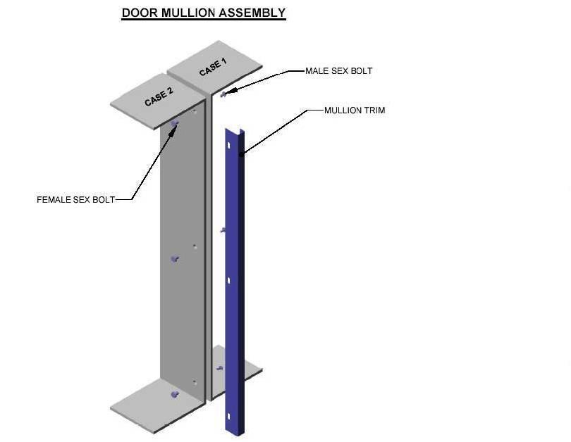
30 Joining Instructions Two or more cases of like models can be joined together to form a continuous line up. Before lining up cases, inspect refrigeration lines, electrical connections and controls to insure cases are in the proper line-up and are in the proper sequence. Reference and become familiar with the below figure, and then join the cases using the instructions that follow. Figure 1 Caulking Diagram Bolt Apply caulking as indicated by phantom line Bolt Bolt Align Bolt Holes on Side of Cases Line Up Bolt Align Bolt Holes on Side of Cases 1. A plexi-glass divider and EPR valve must be used when joining a Q-series case with a non-q-series case. 2. Apply foam insulation tape and caulking around the side of the case as shown in the diagram above. 30

31 3. Remove access covers over line up holes and insert the small line-up bolts (see previous diagram) in the end frame in the bolt hole pattern. Place the special T-nut washer on the 3/8" machine bolt with the hollow section away from the bolt head. Tighten the 3/8" bolts with nut washer into the T-nuts alternately until cases are pulled up tight and the joint is completely sealed. (Reasonable care should be exercised in this procedure to prevent end frame distortion.) Assist pulling case up tight by bumping from opposite end of case or by using pry bar. 4. Inspect joint for proper air and watertight seal inside and outside the case. 5. Replace line up access cover plugs and plates. 6. Move cases as close together as possible and level by using the shims provided (same as original case). Use shelf standard struts for alignment to be sure cases are level. Shelf standards on back wall should be even when leveled properly. WARNING: Cases must be leveled from front to back, end-to-end and supported continuously as needed with shims. 31
32 32
33 Waste Outlet (Drip Pipe) Description and Location These cases are equipped with 1 ½" PVC waste outlet connection that terminates in the center of the 4 and 6 (the 8 and 12 are split into two halves) or for reach-in doors ( door) refrigerator below the insulated bottom. The water seal trap is shipped loose for field installation. Waste Outlet (Drip Pipe) Field Installation Guidelines Improperly installed drip pipes can seriously affect the operation of this case and result in increased maintenance cost. Listed below are some general rules for drip pipe installation 1. Never use a double water seal. 2. Never use a pipe smaller than the size pipe or water seal supplied with the case. 3. Always provide as much fall as possible in drip pipe. (1" fall for each 4' of drip pipe.) 4. Avoid long runs in drip pipe, which make it impossible to provide maximum fall in pipe. 5. Provide a drip space between drip pipe and floor drain or sewer connection. Case Freezing Do not allow drip pipe to come in contact with un-insulated suction lines, which will cause the condensation from your case to freeze. Drain Strainer NOTE: Not all Kysor//Warren cases have drain strainers. This information applies only to the cases equipped with strainers. The drain strainer is used to keep debris or any foreign objects from entering the PVC drain, which could cause blockage. To install, insert into drain until drain strainer stops. It will not be flush. Strainer will exceed hub by 1. DO NOT flatten drain strainer, NOTE: 1 ½ Drain Pipe 33
34 Electrical Connections General Safety Precautions Ensure the kick plate does not come in contact with the case electrical wiring. Live electrical wiring that comes in contact with the case is a shock hazard that may cause severe injury or death by electrocution. Always disconnect the electrical power at the main disconnect when servicing or replacing any electrical component. This includes, but is not limited to items such as fans, heaters, thermostats and light bulbs. Failure to disconnect the electrical power may result in personal injury or death, CAUTION: Failure to properly install electrical wiring and control wiring as per wiring diagram(s), defrost settings, and temperature set-points may result in operational issues such as: increased BTUH load, high product temperature, coil icing, product frosting, and external sweating. 34
35 Wiring Diagram Electric Defrost 35
36 Hot Gas Defrost 36
37 Off-Cycle Defrost 37
38 Optional Diagrams for Remote Condensing Unit & Paragon Timer Electric Defrost with 208V Condensing Unit 38
39 Off-Cycle Defrost with 115V Condensing Unit 39
40 Off-Cycle Defrost 208V with Condensing Unit 40
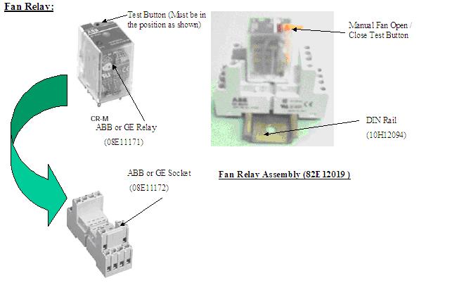
41 Fan Relay Assembly/Wiring 41
42 Wire Number The wires are clearly identified for termination purposes as follows: Component Wire Number Anti-Sweat Heater 1 and 2 Refrigerator Fan Motors and Drain Heater 3 and 4 Lighting Circuit 5 and 6 Defrost Heaters 7 and 8 Temperature Control 9 and 10 Dual Temperature 15 and 16 Defrost Termination Control 17 and 18 Refrigeration Piping and Dehydration Opening a Ferrule Hole The refrigeration lines are located under the deck pans. A refrigeration outlet is provided in the front right hand end of the cases. All refrigeration lines need to be as close to the drain pan as possible so as not to obstruct the air pattern or block the deck pans. 42
43 Recommended Piping Instruction 1. Proper size refrigeration lines are essential to good refrigeration performance. Suction lines are more critical than liquid or discharge lines. Oversized suction lines may prevent good oil return to the compressor. Undersized lines can rob refrigeration capacity and increase operating cost. Consult the technical manual or legend sheet for proper line sizes. 2. Refrigeration lines in cases in line-ups can be reduced. However, the lines should be no smaller than the main trunk lines in at least 1/3 of the cases and no smaller than one size above the case lines to the last case. Reductions should not exceed one line size per case. It is preferred to bring the main trunk lines in at the center of line-up. Liquid lines on systems on hot gas defrost must be increased one line size above the main trunk line for the entire line-up. Individual feed lines should be at the bottom of the liquid header. (See proper liquid line piping diagram.) 3. Do not run refrigeration lines from one system through cases on another system. 4. Use dry nitrogen in lines during brazing to prevent scaling and oxidation. 5. Insulate suction lines from the cases to the compressor with 3/4" wall thickness foam on low temperature cases to provide maximum of 65-degree super heated gas back to the compressor and prevent condensation in exposed areas. Insulate suction lines on medium temperature cases with 1/2" thick insulation in exposed areas to prevent condensate dropoff. 6. Suction and liquid lines should never be taped or soldered together. Adequate heat exchanger is provided in the case. Kysor//Warren recommends use of heat exchanger in all medium and low temperature case that are not mechanically sub-cooled for proper operation. 7. Refrigeration lines should never be placed in the ground unless they are protected against moisture and electrolysis attack. 8. Always slope suction lines down toward the compressor, 2" each 10. Do not leave dips in the line that would trap oil. 9. Provide P traps at the bottom of suction line risers, 4 or longer. Use a double P trap for each 20 of risers. P traps should be the same size as the horizontal line. Consult the technical manual or legend sheet for proper size risers. 10. Use long radius ells and avoid 45 degree ells. 11. Provide expansion loops in suction lines on systems on hot gas defrost. An expansion loop is required for each 100 of straight run. 12. Strap and support tubing to prevent excessive line vibration and noise. 13. Brazing of copper to copper should be with a minimum of 10% silver. Copper to brass or copper to steel should be with 45% silver. 14. Do not use bullhead tees in suction lines. An example is where suction gas enters both ends of the tee and exits the center. This can cause a substantial increase in pressure drop in the suction lines. 43
44 15. When connecting more than one suction line to a main trunk line, connect each branch with an inverted trap. Suction line: 1. Pitch in direction of flow. 2. Suction lines should enter at the top of the branch line. 3. May be reduced by one size at one third of case run load and after the second third. DO NOT reduce below the case suction line size. Expansion Valve and Superheat CAUTION: During service of this equipment, precautions should be taken to prevent loss of refrigerant to the atmosphere. Always install the expansion valve stem cap after making valve adjustments. Setting Superheat The expansion valve furnished with your case has been sized for maximum coil efficiency. To adjust superheat, perform the following: 1. Place a thermocouple near the expansion valve bulb. Read the suction line pressure as near coil as possible. If closest is at the condensing unit, estimate suction line loss at 2 PSIG. 2. Convert coil suction pressure to temperature. The difference between coil temperature and the thermocouple temperature is superheat. Use average superheat when expansion valve is hunting. 3. Do not set the superheat until cases have pulled down to operating temperature and never open or close the valve over ¼ turn between adjustments and allow 10 minutes or more between adjustments. 4. Superheat should be set at 6-8 F. 5. After the initial setting, the superheat should be rechecked when product is stocked and at designed temperature. Superheat Calculations + 33 F Suction Temperature Suction Pressure Example: R F Suction temperature 28 F Suction pressure converted to temperature = +5 F Superheat 66.7 PSIG 44

45 Operation Loading Merchandise should not be placed in the fixture until all controls have been adjusted and the case is at the proper temperature. At no time should the case be stocked beyond the load line or over the front edge of adjustable shelves. Load Limit Air Current Performance Air discharge and return flues must remain open and free of debris or obstruction at all times to provide proper refrigeration and air current performance. Do not allow any product, signs, debris, etc. to block these grilles. Do not use any non-approved shelving, display racks or any accessory that could hamper air current performance. WARNING: Do not walk on top of the cases! This could result in damage to the case and serious personal injury could occur. These cases are not designed to support excessive external weight. Do not use top of cases for storage. Normal Operation 1. Off-Cycle Defrost is standard on medium temperature models. The fans run continuously and defrost termination is by termination Klixon. 2. Electric Defrost Models are standard for low temperature cases. Electric heaters are utilized to melt the frost and ice on the coil. The heaters are located in the air stream underneath the coil. The defrost cycle is time initiated and temperature terminated. Case fans shut off during defrost. During refrigeration the fans start after the evaporator coil temperature reaches 10 F and run continuously thereafter. As a safety precaution, a safety 45
46 cutoff Klixon is wired in series with the defrost heater to turn the heater off at temperatures above 65 F. 3. Hot Gas Defrost Models (optional for parallel compressor operation only) hot gas is routed through the suction line and evaporator coil. It exits the coil through a by-pass around the expansion valve and heat exchanger to return to the liquid line where the condensed liquid is use to feed the other cases on the same parallel case. The evaporator fans are controlled by evaporator temperature through a thermostat. The defrost cycle is time initiated and should be temperature terminated. (See case data information) 4. Single Condensing Case Systems A thermostat should be used to control case temperatures. The thermostat bulb should be mounted in the discharge air (see case data if your case is a single condensing case system). NOTE: Where termination temperatures are given, mechanical defrost termination is required. Cleaning As a general rule, always use mild soap and water to wipe the case down. Special precautions must be taken when cleaning some components of the case. Exterior surfaces should be cleaned with warm water and mild soap to protect and maintain the finish. Do not use cleaners containing abrasive materials or ammonia, which will scratch or dull the finish. The waste outlet should be flushed with water following each cleaning. Interior surfaces may be cleaned with most mild soap formulas, ammonia based cleaners and sanitizing solutions with no harm to the surface. Personal Safety 1. Always shut power off during the cleaning process. Cleaning the case with electrical power applied is a shock hazard that may cause serious injury or death. 2. Do not use hot water on cold glass surfaces. This could cause the glass to shatter and could result in personal injury. Glass fronts and ends should be warm before applying hot water. Case Damage Prevention: 1. Do not use solvent, oil or acidic-based cleaners on any interior surfaces as the surface may become damaged. 2. Do not use abrasive cleaners and scouring pads, as these will mar the finish. 3. Never introduce water into the case faster than the waste outlet can release it. 4. Do not use steam or high pressure systems to clean the case as seals may be broken which will cause the case to leak. Shelves Do not use a hose or submerge shelves in water. When cleaning lighted shelves; wipe down the shelves with a wet sponge or cloth so that water does not enter the light rails. 46

47 Mirrors Mirrors are sheets of clear glass that have a very thin reflective coating applied to one side. These coatings are susceptible to deterioration if certain cleaning solutions and even water are allowed to come in contact with them. Every precaution should be made to keep liquids away from the coated side of the mirrors. If liquids are allowed to flow along the face side of the mirror to its edge, the liquid can seep between the coating and the glass, causing serious damage. Prolong the life of the mirrors Use only mild cleaning solutions (Windex, Solox, or a weak solution of vinegar and water). Do NOT spray liquids on mirrors. Dampen the cleaning cloth, and then use the cloth to wipe the mirror. Wipe water from the mirrors immediately to prevent difficult to remove water spots and also to prevent the water from reaching the mirrors edge. Never use dirty cloths, scrapers or any other abrasive materials for cleaning. Honeycomb Assembly The honeycomb should be cleaned every 6-8 months, depending on store conditions. The honeycomb may be cleaned with a vacuum cleaner or removed to be washed with soap and water. The honeycomb must be completely dry before returning it to the case. Note the position and angle of the honeycomb when removing from the case. Honeycomb must be replaced at the same angle. To remove honeycomb from case, take out screws located here. 47
48 Parts List Common Replacement Parts Part No. Quantity Description 1 DOOR 2 5 DOOR QIV5V/ QIV5V/ QLV5V QDV5V QLV5V QDV5V 1 DR 2 DR 3 DR 4 DR 5 DR Fan Motor STD N/A N/A 09A A10040 N/A Fan Motor PSC 09A A A A Fan Motor ECM 09A A A A Fan Blade, 8 Diameter 09B B B B Honeycomb-White 13A A A A Honeycomb - Black 13A A A A Fan Bracket STD 54V V V V Fan Bracket PSC/ECM 54V V V V Deck Pan Metal 54N N N N Deck Pan White N/A N/A 13A A10625 N/A Deck Pan Black N/A N/A 13A A10624 N/A External Drain Trap 96H H H H Defrost Control (Hot Gas) 08A11217 N/A 08A11217 N/A Defrost Control (Electric) 08A11048 N/A 08A11048 N/A Electric Defrost Safety 08A11050 N/A 08A11050 N/A NOTE: Standard parts are provided in the parts lists. Cases may be equipped with specialty parts that were incorporated into the case(s) at the time they were manufactured. It is important to have the case serial number when contacting Kysor//Warren for replacement parts. 48
49 Warranty Rev DIVISION OF KYSOR INDUSTRIAL CORPORATION 5201 Transport Boulevard Columbus, Georgia ONE-YEAR WARRANTY KYSOR//WARREN warrants to the original purchaser this new equipment and all parts thereof, to be free from defects in material and workmanship under normal use and service. If any part or parts of the equipment should prove defective during the period of one year from installation date (not to exceed one year and thirty days from the date of original shipment from the factory), KYSOR//WARREN hereby guarantees to replace or repair, without charge (F.O.B. Columbus, Georgia), such part or parts as proven defective, and which KYSOR//WARREN S examination disclosed to its satisfaction to be thus defective, with a new or functionally operative part. The liability of KYSOR//WARREN under this warranty shall be limited to claims made by the original purchaser to KYSOR//WARREN or KYSOR//WARREN S authorized dealer or distributor within the warranty period. THIS WARRANTY IS IN LIEU OF ALL OTHER WARRANTIES, EXPRESSED, IMPLIED OR STATUTORY, INCLUDING, BUT NOT LIMITED TO ANY WARRANTY OF MERCHANTABILITY OR FITNESS, AND ALL OTHER OBLIGATIONS OR LIABILITIES OF KYSOR//WARREN. I. GLAZING: Glass is not guaranteed against breakage. If this refrigerator is equipped with a glazing assembly carrying the manufacturer s brand name (Thermopane, Twindow, etc.), the manufacturer s glazing warranty in effect at the time of this shipment is extended to that assembly. II. BULBS: Light bulbs and fluorescent lamp tubes are not covered by any warranty for length of life or for any type of breakage. III. THIS WARRANTY SHALL NOT APPLY: 1. To the condensing unit used with refrigerated equipment unless same was sold and shipped by KYSOR//WARREN. 2. When this equipment or any part thereof is damaged by accident, fire, flood, act of God, alteration, abuse, misuse, tampering, when the original model and serial number plate has been altered, defaced, or removed or used other than the recommended application by KYSOR//WARREN. 3. When this equipment or any part thereof is subject to operation on low, high or improper voltages. Low and high voltage is defined as more than a 5% drop below or 10% higher than name plate voltage ratings. NOTE: Proper field supply voltage to the equipment is the responsibility of the owner (end user). 4. To damage caused by overloading shelves or wire racks beyond the specified weight limits. The maximum weight limit for standard KYSOR//WARREN shelves and wire racks is 30lbs per square foot. 49
50 5. When this equipment or any part thereof is damaged, or when operation is impaired, due to failure to follow installation manual. 6. NOTE: Proper installation is the responsibility of the installer, owner (end user). 7. Operational issues caused by ambient environmental conditions outside of the specified limits. All KYSOR//WARREN equipment is specified to operate in a conditioned ambient environment not to exceed 75 degrees Fahrenheit or 55% relative humidity. NOTE: Providing specified ambient environmental conditions are the responsibility of the owner (end user). 8. To equipment with final destinations unknown to KYSOR//WARREN as indicated on the original sales order. 9. To labor cost for repair or replacement of parts. 10. To special or expedited freight or shipping charges or to customs duties to any country. 11. If the Warranty holder fails to comply with all the provisions, terms and conditions of this Warranty. Parts replaced under this Warranty are warranted only through the remainder of the original Warranty. KYSOR//WARREN may, at its option and in its discretion, elect to honor this Warranty and to disregard the original purchaser s non-compliance with any of the provisions, terms and conditions of the Warranty. THIS WARRANTY DOES NOT COVER CONSEQUENTIAL DAMAGES. KYSOR//WARREN shall not be liable under any circumstances for any consequential damages, including loss of profits, additional labor costs, loss of refrigerant or food products, or injury to person or property caused by defective material or parts or for any delay in the performance of this Warranty due to causes beyond its control. The foregoing shall constitute the sole and exclusive remedy of any purchase and the sole and exclusive liability of KYSOR//WARREN in connection with this product. NOTE: IN THE CONSTANT EFFORT TO IMPROVE OUR PRODUCTS, WE RESERVE THE RIGHT TO CHANGE AT ANY TIME SPECIFICATIONS, DESIGN, OR PRICES WITHOUT INCURRING OBLIGATION. 50
INSTALLATION & OPERATION MANUAL QDV6V-A QIV6V-A, QLV6V-A REACH-IN DISPLAY CASES IMPORTANT KEEP IN STORE FOR FUTURE USE. Part No. 31E11043 Date: 1/5/15
 Part No. 31E11043 Date: 1/5/15 5201 Transport Boulevard Columbus, GA 31907 706-568-1514 INSTALLATION & OPERATION MANUAL QDV6V-A QIV6V-A, QLV6V-A REACH-IN DISPLAY CASES IMPORTANT KEEP IN STORE FOR FUTURE
INSTALLATION & OPERATION MANUAL
 Part No. 31E11044 Date: 4/11/11 5201 Transport Boulevard Columbus, GA 31907 706-568-1514 INSTALLATION & OPERATION MANUAL QFGCEID-A, QFGTD-A QNGCEID-A REACH-IN DISPLAY CASES IMPORTANT KEEP IN STORE FOR
Installation & Operation Manual
 Part Number: 31E11040 Date Revised: 11/14/2011 5201 Transport Boulevard Columbus, GA 31907 706-568-1514 Installation & Operation Manual QWM1GD Single Deck Display Case IMPORTANT KEEP IN STORE FOR FUTURE
QM5, QM5G Multi-Deck Meat Display Case. Part Number: 31E03028 Date: 08/13/2007
 Part Number: 31E03028 Date: 08/13/2007 5201 Transport Boulevard Columbus, GA. 31907 706-568-1514 Installation & Operation Manual QM5, QM5G Multi-Deck Meat Display Case IMPORTANT KEEP IN STORE FOR FUTURE
Installation and Operation Manual
 series Installation and Operation Manual FGCEID GLASS DOOR REACH-IN This refrigerator conforms to the Commercial Refrigerator Manufacturers Association s Health and Sanitation Standard. series Page 2 INSTALLATION
IMPORTANT KEEP IN STORE FOR FUTURE USE
 Part Number: 31E11030 Date: 8/24/2011 5201 Transport Boulevard Columbus, GA 31907 706-568-1514 Installation & Operation Manual QM2T(E) QM3T(E) Wide Island Multi-Deck Display Case IMPORTANT KEEP IN STORE
INSTALLATION & OPERATION MANUAL
 series K//W Part #:31E03-027 Date: 9-00 Supersedes: INSTALLATION & OPERATION MANUAL M4N3 Multi-Deck, Narrow, Meat Merchandiser This case conforms to the Commercial Refrigerator Manufacturers Association
Installation & Operation Manual
 5201 Transport Boulevard Columbus, GA. 31907 706-568-1514 Installation & Operation Manual QFGCEIX/Low Temperature Reach-In Display Cases with modular condensing unit IMPORTANT KEEP IN STORE FOR FUTURE
Introductions General Information. Receiving/Shipping Damage/Lost Items
 Page 2 Table of Contents Introductions General Information... 4 Case Description... 4 Receiving/Shipping Damage/Lost Items... 4 Refrigerant... 5 Condensing Unit... 5 Condensate Evaporator Pan Heater:.
Introductions General Information
 Table of Contents Introductions General Information... 4 Case Description... 4 Receiving/Shipping Damage/Lost Items... 4 Refrigerant... 5 Glass Cylinders... 5 Plan View and Cross Section... 6 Case Data...
Introductions General Information. Receiving/Shipping Damage/Lost Items
 Page 2 Table of Contents Introductions General Information... 4 Case Description... 4 Receiving/Shipping Damage/Lost Items... 4 Refrigerant... 5 Condensing Unit... 5 Plan View and Cross Section... 6 Case
Installation & Operation Manual. STRATUS Multi- Deck Display Case. Stratus Multi Deck Installation and Operations. Manual
 Installation & Stratus Multi Deck Installation and Operations Operation Manual Manual KW-IOM-2030 January 2015 Part No. 31E02030 Contents STRATUS Multi- Deck Display Case Introduction General Information
Installation & Operation Manual. STRATUS Multi- Deck Display Case. Stratus Multi Deck Installation and Operations. Manual
 Installation & Stratus Multi Deck Installation and Operations Operation Manual Manual KW-IOM-2040 March 2013 Part No. 31E02040 Contents STRATUS Multi- Deck Display Case Introduction General Information
Installation & Operation Manual. STRATUS Multi- Deck Display Case. Stratus Multi Deck Installation and Operations. Manual
 Installation & Stratus Multi Deck Installation and Operations Operation Manual Manual KW-IOM-2042 January 2015 Part No. 31E02042 Contents STRATUS Multi- Deck Display Case Introduction General Information
Installation & Operation Manual. STRATUS Multi- Deck Display Case. Stratus Multi Deck Installation and Operations. Manual
 Installation & Stratus Multi Deck Installation and Operations Operation Manual Manual KW-IOM-2098 March 2013 Part No. 31E02098 Contents STRATUS Multi- Deck Display Introduction General Information 2 Plan
Installation & Operation Manual. STRATUS Multi- Deck Display Case. Stratus Multi Deck Installation and Operations. Manual
 Installation & Stratus Multi Deck Installation and Operations Operation Manual Manual KW-IOM-2031 January 2015 Part No. 31E02031 Contents STRATUS Multi- Deck Display Case Introduction General Information
HANDBOOK O3EIF MEAT CASES INSTALLATION & OPERATION
 HANDBOOK INSTALLATION & OPERATION O3EIF MEAT CASES Table of Contents General Information... 2 Using Casters... 3 Case Dimensions... 4 Case Operations... 5 Line Up & Trim Out... 6 Piping: Refrigeration
Installation & Operation Manual. STRATUS Multi- Deck Display Case. Stratus Multi Deck Installation and Operations. Manual
 Installation & Stratus Multi Deck Installation and Operations Operation Manual Manual KW-IOM-2142 January 2015 Part No. 31E02142 Contents STRATUS Multi- Deck Display Case Introduction General Information
Installation & Operation Manual. Reach-In Display Case. KW-IOM-2149 July 2016 Part No. 31E02149
 Installation & Operation Manual KW-IOM-2149 July 2016 Part No. 31E02149 Contents Reach-In Display Case Introduction General Information 3 Plan and Cross Views 5 Case Data 7 Case Installation 18 Electrical
QLV5V-A - Glass Door Eliminator - Frozen Food. QIV5V-A - Glass Door Eliminator - Ice Cream. Applications: Specification Sheet 2 DR 3 DR 4 DR 5 DR
 CASE DATA AMPS - # of Doors 2 DR 3 DR 4 DR 5 DR Anti-Sweat 2.43 3.43 4.35 5.40 PSC Fan 0.52 0.78 1.04 1.30 STD Fan 1.04 1.56 2.08 2.60 ECM Fan 0.50 0.75 1.00 1.25 Light (T8 ELS) 1.39 1.80 2.32 2.79 LED
Installation & Operation Manual. STRATUS Multi- Deck Display Case. Stratus Multi Deck Installation and Operations. Manual
 Installation & Stratus Multi Deck Installation and Operations Operation Manual Manual KW-IOM-2075 March 2013 Part No. 31E02075 Contents STRATUS Multi- Deck Display Case Introduction General Information
INSTALLATION AND OPERATING MANUAL
 INSTALLATION AND OPERATING MANUAL Refrigerated Merchandisers with Air-Over Displays Refrigerated Low-Profile Mobile Merchandiser Refrigerated High-Profile Mobile Merchandiser Refrigerated Grab-N-Go Merchandiser
INSTALLATION AND OPERATING MANUAL
 INSTALLATION AND OPERATING MANUAL Refrigerated Island Merchandiser FOR PARTS & SERVICE Contact: Piper Products, Inc. Phone: (800) 544-3057 Ask for Service Department IMPORTANT! This manual contains important
Installation & Operation Manual. Reach-In Display Case. Stratus Multi Deck Installation and Operations. Manual
 Installation & Stratus Multi Deck Installation and Operations Operation Manual Manual KW-IOM-2149 January 2016 Part No. 31E02149 Contents Reach-In Display Case Introduction General Information 3 Plan and
Field Top Mounted Condensing Unit
 Field Top Mounted Condensing Unit INSTALLATION & OPERATIONS MANUAL RF/RF-N, RM/RM-N IMPORTANT Keep in store for future reference! REVISION HISTORY VERSION 1.0 New manual This manual is specific to the
ISLAND PRODUCE MODELS: OIP, OIPB, &OIPBB INSTALLATION & OPERATION HANDBOOK. P054956H Rev. 7 11/06 COMPONENT
 ISLAND PRODUCE C A S E S MODELS: OIP, OIPB, &OIPBB INSTALLATION & OPERATION HANDBOOK COMPONENT P054956H Rev. 7 11/06 Welcome to the ORIGIN 2 display case family. We re very pleased you joined us. This
POLAR TEMP FARM MORTALITY UNIT OPERATION MANUAL
 POLAR TEMP FARM MORTALITY UNIT OPERATION MANUAL www.polartemp.com TABLE OF CONTENT Disclaimer.......................................... Page 3 Inspection, unpacking and FMU setup.................. Page
CS/CD/CP AIR COOLED CONDENSING UNITS (P/N E207120C R2)
") CS*/CD*/CP* Series Air Cooled Condensing Units Operating and Installation Manual CS/CD/CP AIR COOLED CONDENSING UNITS (P/N E207120C R2) TABLE OF CONTENTS I. Receipt of Equipment 2 II. Piping...4 III. System
CS*/CD*/CP* Series Air Cooled Condensing Units Operating and Installation Manual CS/CD/CP AIR COOLED CONDENSING UNITS (P/N E207120C R2) TABLE OF CONTENTS I. Receipt of Equipment 2 II. Piping...4 III. System
INSTALLATION AND OPERATING MANUAL
 INSTALLATION AND OPERATING MANUAL Salad Bars Olive Bars Food Prep Cases Refrigerated Cases with Air-Over Displays Refrigerated Cases with Coppered Cold Well Displays Cases with Under-Counter Refrigerators
Blue Air. Commercial Refrigeration Inc. Installation & Operation Manual Ice Cream Freezers
 Blue Air Commercial Refrigeration Inc. Installation & Operation Manual Ice Cream Freezers Please read this manual completely before installing or operating this unit! BACF11 BACF15 BACRF14 Blue Air reserves
SERIES NIM. Low Temperature Merchandisers PLEASE READ THIS MANUAL BEFORE USING THE PRODUCT
 SERIES NIM Low Temperature Merchandisers PLEASE READ THIS MANUAL BEFORE USING THE PRODUCT Hussmann Monterrey, Mexico Carretera Mexico-Laredo KM. 1009 Cienga de Flores, Nuevo Leon 65550 Mexico Phone: (52)
GCG-10. Instruction Manual. G-Series Cooler. Manual is for the following models: GCG-10-N33EB G-10-N33EB UPRIGHT COOLER
 G-Series Cooler GCG-10 UPRIGHT COOLER Manual is for the following models: GCG-10-N33EB G-10-N33EB Instruction Manual Manual is for the following models: GCG-10-N33EB G-10-N33EB Instruction Manual GCG-10
INSTRUCTIONS FOR OPERATION AND CARE OF. P.O. Box 3527 City of Industry, CA, , U.S.A
 INSTRUCTIONS FOR OPERATION AND CARE OF GLACIERFREEZE GF-12 P.O. Box 3527 City of Industry, CA, 91744-0527, U.S.A. 800-782-7706 626-968-6681 www.whitehallmfg.com Member of 6702-488-000 August 2012 WARNING
MYSTICOOL Max Valve System with Xstream and A.R.M.E.D. Technology Service & Installation Instructions Page 1
 Page 1 WHY should I install the MYSTICOOL Max Valve System? XDX is more efficient, saving on power consumption. Use of XDX system decreases defrost cycles. XDX maintains more consistent product temperatures,
SOLARHOT. SuperVox. Description / Applications System Overview. Installation/ Owner s Manual
 SOLARHOT SuperVox Installation/ Owner s Manual Description / Applications System Overview The SOLARHOT SuperVox solar thermal glycol system. The SuperVox allows for easy installation of large solar water
3-DECK ISLAND PRODUCE INSTALLATION & OPERATION HANDBOOK. P053096D Rev. 9 11/10 COMPONENT
 3-DECK ISLAND PRODUCE C A S E S M O D E L S : O 3 I P & O 3 I P B INSTALLATION & OPERATION HANDBOOK COMPONENT P053096D Rev. 9 11/10 Welcome to the Hill PHOENIX display case family. We re very pleased
Installation & Operation Manual Ice Cream Freezers
 Installation & Operation Manual Ice Cream Freezers Please read this manual completely before installing or operating this unit! BACF11 BACF15 Blue Air reserves the right to make product modification at
A112408B/S-VR-UBL TECHNICAL ASSISTANCE TOLL FREE TELEPHONE NUMBER: Technical Assistance Fax:
 INSTALLATION, OPERATION AND MAINTENANCE INSTRUCTIONS Vandal Resistant Refrigerated Universal Bi-Level AquaAccess Barrier Free, Wall Mounted Water Cooler OR Alternate Configuration A112408B/S-VR-UBL TECHNICAL
REFRIGERATED DROP-INS (2-6)FT-DI Installation and Operating Manual
FT-DI Installation and Operating Manual") REFRIGERATED DROP-INS (2-6)FT-DI Installation and Operating Manual For service information call 800-544-3057 Please have the following information available before calling. Information can be found on
REFRIGERATED DROP-INS (2-6)FT-DI Installation and Operating Manual For service information call 800-544-3057 Please have the following information available before calling. Information can be found on
INSTALLATION AND SERVICE MANUAL REMOTE TYPE DISPLAY CASE
 Multi-Deck Self Service Fresh Meat Merchandiser Multi-Deck Self Service Fresh Meat Merchandiser FPW-EXA085 FPW-EXA085 FPW-EXA025 FPW-EXA025 INSTALLATION AND SERVICE MANUAL REMOTE TYPE DISPLAY CASE TABLE
QDV5V - 1 Door Standard (Gemtron)
") CASE DATA AMPS 44 40 1/2 8 1/8 18 3/4 1 5/8 (END) ELECTRICAL 2 4 3/4 1 Anti-Sweat 0.51 PSC Fan / # Fans 0.37/1 ECM Fan / # Fans 0.30/1 T8 Lights 0.98 LED Lights 0.26 All electrical data based on 115V and
CASE DATA AMPS 44 40 1/2 8 1/8 18 3/4 1 5/8 (END) ELECTRICAL 2 4 3/4 1 Anti-Sweat 0.51 PSC Fan / # Fans 0.37/1 ECM Fan / # Fans 0.30/1 T8 Lights 0.98 LED Lights 0.26 All electrical data based on 115V and
DUAL VOLTAGE REFRIGERATORS 220/240 VOLTS AC AND 12/24 VOLTS DC INSTALLATION AND OWNER S MANUAL
 DUAL VOLTAGE REFRIGERATORS 220/240 VOLTS AC AND 12/24 VOLTS DC INSTALLATION AND OWNER S MANUAL Service Information If service or parts are required, contact the nearest Norcold Service Center. To find
XSTREAM Valve System With A.R.M.E.D. Technology Service & Installation Instructions Page 1
 Page 1 WHY should I install the XSTREAM Valve System? XDX is more efficient, saving on power consumption. Use of XDX system decreases defrost cycles. XDX maintains more consistent product temperatures,
Horizontal Bottle Cooler Installation and Operation Manual
 Speeds Up the Pace of Innovation Horizontal Bottle Cooler Installation and Operation Manual Please read this manual completely before attempting to install or operate this equipment! TBC-50SD, 50SB/ TBC-95SD,
INSTALLATION AND OPERATING MANUAL
 INSTALLATION AND OPERATING MANUAL Refrigerated Cases with Air-Over Displays Refrigerated High Profile Grab-N-Go FOR PARTS & SERVICE Contact: Piper Products, Inc. Phone: (800) 544-3057 Ask for Service Department
RPI Industries, Inc.
 IMPORTANT: THE FOLLOWING INFORMATION SHOULD BE RETAINED FOR FUTURE REFERENCE RPI Industries, Inc. building a better case for sales BAKERY and DELI USE AND SERVICE MANUAL WARRANTY INFORMATION SPECIFICATIONS
WMHP Series R410a Heat Pump INSTALLATION INSTRUCTIONS
 WMHP Series R410a Heat Pump INSTALLATION INSTRUCTIONS **WARNING TO INSTALLER, SERVICE PERSONNEL AND OWNER** Altering the product or replacing parts with non authorized factory parts voids all warranty
Condensing Unit Installation and Operating Instructions
 Bulletin WCU_O&I 01 June 2003 Condensing Unit Installation and Operating Instructions WCU Air Cooled Condensing Unit Table of Contents Section 1. Section 2. Section 3. Section 4. Section 5. Section 6.
Milk Coolers Installation and Operation Manual Please read this manual completely before attempting to install or operate this equipment!
 Turbo Air Speed up the Pace of Innovation CAUTION! PLEASE KEEP POWER SWITCH ON BEFORE OPERATING THIS EQUIPMENT Milk Coolers Installation and Operation Manual Please read this manual completely before attempting
INSTALLATION, OPERATION AND MAINTENANCE INSTRUCTIONS
 INSTALLATION, OPERATION AND MAINTENANCE INSTRUCTIONS AquaArctic Remote Water Chiller A9100080 -A TECHNICAL ASSISTANCE TOLL FREE TELEPHONE NUMBER: 1.800.591.9360 Technical Assistance Fax: 1.626.855.4894
Before Putting Into Use. Important. Tips for Energy Savings
 Before Putting Into Use Before connecting the appliance to the power supply, let it stand for about 2 hours, which will reduce a possibility of malfunctions in the cooling system due to transport handling.
Condensing Unit Installation and Operating Instructions
 Bulletin ACU_O&I 02 August 2016 Condensing Unit Installation and Operating Instructions ACU Air Cooled Condensers Table of Contents Section 1. General Information... 2 Section 2. Refrigeration Piping...
OWNER/OPERATOR MANUAL COMPONENTS, INSTALLATION, OPERATION AND SERVICE INSTRUCTIONS
 OWNER/OPERATOR MANUAL COMPONENTS, INSTALLATION, OPERATION AND SERVICE INSTRUCTIONS REFRIGERATED COMPRESSED AIR DRYER WRA-0050 WRA-0200 WARNING READ ALL INFORMATION IN THIS MANUAL BEFORE BEGINNING INSTALLATION
RVZC30 (and BB/T/TBB/WA), RVZP30 (and BB/T/TBB/WA), RVC24
, RVZP30 (and BB/T/TBB/WA), RVC24") 2 TABLE OF CONTENTS INTRODUCTION... 4 DELIVERY INSPECTION... 4 PACKAGING... 4 LOCATION... 4 Figure 1: Case label information... 5 INSTALLATION... 6 Leveling... 6 Figure 2: Leveling cases prior to joining...
2 TABLE OF CONTENTS INTRODUCTION... 4 DELIVERY INSPECTION... 4 PACKAGING... 4 LOCATION... 4 Figure 1: Case label information... 5 INSTALLATION... 6 Leveling... 6 Figure 2: Leveling cases prior to joining...
NFW, NCW, NFWG, NCWG, NFWE, NCWE
 Installation & Service Manual WIDE ISLAND FROZEN FOOD & ICE CREAM MERCHANDISERS Low Temperature Self Serve Display Cases This manual has been designed to be used in conjunction with the General (UL/NSF)
Installation, Operation, and Maintenance Information
 Installation, Operation, and Maintenance Information Low Velocity Unit Coolers Bulletin No. IOM 110.3 Table of Contents Inspection... 2 Installation... 2 4 General... 2 Location... 2 Drain Line... 3 Refrigerant
e Bath Fan with Light User s Guide
 e Bath Fan with Light User s Guide abfl100rnl, BFL125RNL Item Stock Number(s): BFL100RNL, BFL125RNL IMPORTANT INSTRUCTIONS - OPERATING MANUAL READ AND SAVE THESE INSTRUCTIONS READ CAREFULLY BEFORE ATTEMPTING
Instruction Manual. 36 in. and 42 in. Popcorn Staging Cabinets
 Instruction Manual 36 in. and 42 in. Popcorn Staging Cabinets Model Series 2856 and 2855 42 in. Model 2855-00-000 36 in. Model 2856-00-000 10700 Medallion Drive, Cincinnati, Ohio 45241-4807 USA 2016 Gold
Hot Dog Roller Grills
 Part No. 87630 Hot Dog Roller Grills Model No. 8022, 8022PE, 8023, 8023SL, 8023PE, 8024, 8024PE, 8024SL, 8025, 8025SL Cincinnati, OH 45241-4807 USA SAFETY PRECAUTIONS DANGER Machine must be properly grounded
e Heater/Exhaust Fan/Light User s Guide
 e Heater/Exhaust Fan/Light User s Guide abflh70l, BFLH85L Item Stock Number(s): BFLH70L, BFLH85L IMPORTANT INSTRUCTIONS - OPERATING MANUAL READ AND SAVE THESE INSTRUCTIONS READ CAREFULLY BEFORE ATTEMPTING
RPI Industries, Inc.
 RPI Industries, Inc. AIR SCREEN and SELF-SERVE OPERATION AND SERVICE MANUAL WARRANTY INFORMATION For Models Olympus Bandit Bravo SCAS36R SCRFC3660R SCRFC3648R SCAS48R SCRFC4860R SCRFC4848R SCAS60R SCRFC6060R
WMWLB / WMWFM / WTWLB / WTWFM Series Hydronic Heating Unit
 January 2008 WMWLB / WMWFM / WTWLB / WTWFM Series Hydronic Heating Unit Installation Operation Maintenance The units are designed for permanent up flow, counter flow, or horizontal left or right airflow
Instruction Manual. Astro Staging Cabinet
 Instruction Manual Astro Staging Cabinet 10700 Medallion Drive, Cincinnati, Ohio 45241-4807 USA 2017 Gold Medal Products Co. Part No. 40269 SAFETY PRECAUTIONS DANGER Machine must be properly grounded to
Instruction Manual. Cheddar Easy All-In-One Cheese Corn Shop
 Instruction Manual Cheddar Easy All-In-One Cheese Corn Shop Model No. 2703-00-000 10700 Medallion Drive, Cincinnati, Ohio 45241-4807 USA 2017 Gold Medal Products Co. Part No. 110028 SAFETY PRECAUTIONS
SERIES NAV S Display Merchandisers
 SERIES NAV S Display Merchandisers Medium Temperature Merchandisers PLEASE READ THIS MANUAL BEFORE USING THE PRODUCT Installation & Operation Manual P/N 2400204D NAV S Series May 2006 HUSSMANN CORPORATION
JUMBO ISLAND FROZEN FOOD/ICE CREAM/MEDIUM TEMP MERCHANDISERS Low, Medium and Dual Temperature Self Serve Display Cases
 Installation & Service Manual JUMBO ISLAND FROZEN FOOD/ICE CREAM/MEDIUM TEMP MERCHANDISERS Low, Medium and Dual Temperature Self Serve Display Cases This manual has been designed to be used in conjunction
WKS 4000 SERIES (USA only) --INSTALLATION INSTRUCTIONS--
 --INSTALLATION INSTRUCTIONS--") 8610 Production Avenue San Diego, California 92121 (858) 566-7465 Fax (858) 566-1943 WKS 4000 SERIES (USA only) --INSTALLATION INSTRUCTIONS-- Thank you for choosing a BREEZAIRE cooling unit. We believe
8610 Production Avenue San Diego, California 92121 (858) 566-7465 Fax (858) 566-1943 WKS 4000 SERIES (USA only) --INSTALLATION INSTRUCTIONS-- Thank you for choosing a BREEZAIRE cooling unit. We believe
GCG-9. Instruction Manual. G-Series Cooler. Manual is for the following models: GCG-9-N13EB G-9-N13EB GCG-9-B13EB UPRIGHT COOLER
 G-Series Cooler UPRIGHT COOLER Manual is for the following models: -N13EB G-9-N13EB -B13EB Instruction Manual FOR YOUR FUTURE REFERENCE This easy-to-use manual will guide you in getting the best use of
L6FA. MULTI-SHELF FROZEN FOOD MERCHANDISER Low Temperature Self Serve Display Cases
 Installation & Service Manual L6FA MULTI-SHELF FROZEN FOOD MERCHANDISER Low Temperature Self Serve Display Cases This manual has been designed to be used in conjunction with the General Installation &
MODEL 925W FEATURES: ELECTRICAL DATA: DIMENSIONS: SHIPPING INFORMATION: FOOD WARMING/ MERCHANDISING CABINET
 FOOD WARMING/ MERCHANDISING CABINET MODEL 925W This warmer/merchandiser provides heated circulating air to keep foods fresh and evenly warmed. It is constructed of stainless steel and tempered glass for
KR Series Air Defrost Unit Coolers Operating and Installation Manual
 KR Series Air Defrost Unit Coolers Operating and Installation Manual KR Air Defrost Unit Coolers (PN E108317_L) TABLE OF CONTENTS 1 RECEIPT OF EQUIPMENT... 2 1.1 INSPECTION... 2 1.2 LOSS OF GAS HOLDING
G-7s. Instruction Manual. G-Series Cooler COUNTERTOP COOLER. Part No.11IPA
 G-Series Cooler COUNTERTOP COOLER Part No.11IPA-061000 Instruction Manual FOR YOUR FUTURE REFERENCE This easy-to-use manual will guide you in getting the best use of your cooler. Remember to record the
G-10s. Instruction Manual. G-Series Cooler UPRIGHT COOLER. Part No.11IPA
 G-Series Cooler UPRIGHT COOLER Part No.11IPA-062800 Instruction Manual FOR YOUR FUTURE REFERENCE Thank you for using our product. This manual will guide you in getting the best use of your cooler. Remember
Use and Care Manual. Flammable Material Storage Refrigerator LRBFS06W1HC
 Use and Care Manual Flammable Material Storage Refrigerator LRBFS06W1HC 7085 471-00 Table of Contents Table of Contents Page Please Read and Follow these Instructions... 2 California Proposition 65...
e Bath Fan with Light User s Guide
 e Bath Fan with Light User s Guide abfl50uq, BFL60UQ, BFL70, BFL85 Item Stock Number(s): BFL50UQ, BFL60UQ, BFL70, BFL85 IMPORTANT INSTRUCTIONS - OPERATING MANUAL READ AND SAVE THESE INSTRUCTIONS READ CAREFULLY
G-10f/GCG-10f UPRIGHT COOLER
 G-Series Cooler G-10f/GCG-10f UPRIGHT COOLER Manual is for the following models: G-10F, G-10-F33EB GCG-10F, GCG-10-F33EB GCG-10F2, GCG-10-F233EB G-10-F33EB-HC, GCG-10-F33EB-HC GCG-10-F233EB-HC Instruction
Turbo Air Speed up the Pace of Innovation TBB-4SB CAUTION! PLEASE KEEP POWER SWITCH ON BEFORE OPERATING THIS EQUIPMENT
 Turbo Air Speed up the Pace of Innovation CAUTION! PLEASE KEEP POWER SWITCH ON BEFORE OPERATING THIS EQUIPMENT Underbar Equipment Back Bars Installation and Operation Manual Please read this manual completely
COMMERCIAL REFRIGERATOR INSTRUCTION MANUAL
 COMMERCIAL REFRIGERATOR INSTRUCTION MANUAL Model No.: TGM-69R FEATURE CHART ADVERTISING PANEL FLOURESCENT SWITCH COOLING FAN FLOURESCENT LAMP EVAPORATOR INNER DRAIN PAN SHELF DOOR HANDLE GLASS DOOR CONDENSER
RPI Industries, Inc.
 RPI Industries, Inc. AIR SCREEN and SELF-SERVE OPERATION AND SERVICE MANUAL WARRANTY INFORMATION For Models Stratus SCRFC48R-SSI SCRFC60R-SSI SCRFC72R-SSI SCRFC48R-SSII SCRFC72R-SSII SCRFC48R-SSIII SCRFC72R-SSIII
REAR LOAD DAIRY INSTALLATION & OPERATION HANDBOOK P056170D. Rev /10 COMPONENT
 REAR LOAD DAIRY C A S E S M O D E L : O 5 D R & O 5 D R H INSTALLATION & OPERATION HANDBOOK P056170D COMPONENT Rev. 13 11/10 Welcome to the Hill PHOENIX display case family. We re very pleased you joined
PARALLEL RACK SYSTEM INSTALLATION & OPERATIONS MANUAL With Master Rack Compressor Sequencer
 PARALLEL RACK SYSTEM INSTALLATION & OPERATIONS MANUAL With Master Rack Compressor Sequencer 5/16 Rev. A 57-02509 2 Contents INTRODUCTION... 4 WARNING LABELS AND SAFETY INSTRUCTIONS... 5 PS SERIES PARALLEL
For Additional Copies Please Contact:
 Service & Installation Instructions Keep this booklet for Future Reference BWU SERIES BWU-BCC SERIES BWU-RB SERIES For Additional Copies Please Contact: Hillphoenix Barker Specialty Products 703 Franklin
ref. com Owner s Manual for models: A Step Above the Standard Thank you for choosing EVEREST
 www.everest ref. com Owner s Manual for models: Back Bar Coolers " Deep Back Bar Coolers Glass Door Back Bar Coolers " Deep Galss Door Back Bar Coolers " Deep Galss Sliding Door Back Bar Coolers EBB3,
InstructIon Manual KrEs EQuIPMEnt stands
 Instruction Manual Instruction Manual SELF-CONTAINED AND REMOTE Kairak KRES model refrigerated equipment stand units are available in many lengths from 36 to 120 inches long. These units are available
OPERATING INSTRUCTIONS
 OPERATING INSTRUCTIONS SPECIALTY REFRIGERATED TRANSPORT CABINETS FOR SATELLITE LOCATIONS RBQ-96 Caution: Read the instructions before using the machine. CONGRATULATIONS......and thank you for purchasing
WCPT-3 and WCPT-4. Effective Date: 2017 IMPORTANT INFORMATION READ BEFORE USE. Drop-in Display Cases
 WCPT-3 and WCPT-4 Service and Installation Manual Please read this manual completely before attempting to install or operate this equipment! Notify carrier of damage! Inspect all components immediately.
Instruction Manual MODEL: GDUF Cu. Ft. Capacity 120V~, 60Hz, 115W
 Stock up on your family favorites! Upright Freezer Montgomery Ward Customer Service 3650 Milwaukee Street, Madison, WI 53714 8:00 am to Midnight, Monday through Friday Wards.com 1 888 557 3848 Instruction
Outdoor and Indoor Electric Refrigerator Model COAR
 Outdoor and Indoor Electric Refrigerator Model COAR USER S MANUAL COAR PLEASE READ THE MANUAL THOROUGHLY PRIOR TO EQUIPMENT SET-UP, OPERATION AND MAINTENANCE. - 1 - INSTALLATION IMPORTANT!!! PLEASE READ
OIM OIM. Medium Temp Island Merchandiser 8' & 12' (Deli / Meat) REFERENCE NOTES FOR ENGINEERING DATA:
 REFERENCE NOTES FOR ENGINEERING DATA:") REFERENCE NOTES FOR ENGINEERING DATA: "0.00" indicates that the feature is not an option on this case model LED Lights Only. Cornice lights are either standard or high output. Shelf Lights are standard
REFERENCE NOTES FOR ENGINEERING DATA: "0.00" indicates that the feature is not an option on this case model LED Lights Only. Cornice lights are either standard or high output. Shelf Lights are standard
Instruction Manual. Portion Cup Cheese Warmer
 Instruction Manual Portion Cup Cheese Warmer Model No. 5581-00-100, 5581-01-100, and 5581-00-101 10700 Medallion Drive, Cincinnati, Ohio 45241-4807 USA 2017 Gold Medal Products Co. Part No. 74797 SAFETY
UNDERCOUNTER REFRIGERATORS AND FREEZERS Installation, Operation and Maintenance Instructions
 UNDERCOUNTER REFRIGERATORS AND FREEZERS Installation, Operation and Maintenance Instructions Please read this manual completely prior to installing and operating this equipment. This manual describes how
REFRIGERATED PREP TABLES Installation, Operation and Maintenance Instructions
 REFRIGERATED PREP TABLES Installation, Operation and Maintenance Instructions Please read this manual completely prior to installing and operating this equipment. This manual describes how to install,
HD-26, HD-36, HD-48 Heated Displays
 HD-26, HD-36, HD-48 Heated Displays This manual contains important information regarding your Admiral Craft unit. Please read this manual thoroughly prior to equipment set-up, operation and maintenance.
Instruction Manual. Double Candy Apple Cooker
 Instruction Manual Double Candy Apple Cooker Model No. 4416 10700 Medallion Drive, Cincinnati, Ohio 45241-4807 USA 2014 Gold Medal Products Co. Part No. 46841 SAFETY PRECAUTIONS DANGER Machine must be
ThermoSaver TM Hot Gas Defrost System
 PRODUCT DATA, APPLICATION & INSTALLATION GUIDE Supplement to Condensing Unit Installation and Maintenance Manual Bulletin B40-THERM-PDI-14 1069132 ThermoSaver TM Hot Gas Defrost System For use on select
Installation & Service Manual
 Installation & Service Manual NFJCX, NCJCX, NTJCX, JUMBO ISLAND FROZEN FOOD/ICE CREAM/MEDIUM TEMP MERCHANDISERS Low, Medium and Dual Temperature Self Serve Display Cases This manual has been designed to
Refrigerator Freezer Installation and Operation Manual
 Speeds Up the Pace of Innovation CAUTION! Refrigerator Freezer Installation and Operation Manual PLEASE KEEP POWER SWITCH ON BEFORE OPERATING THIS EQUIPMENT Please read this manual completely before attempting
BEFORE USE, PLEASE READ AND FOLLOW ALL SAFETY RULES AND OPERATING INSTRUCTIONS
 WINE CELLAR Model SWC1840 Owner s Manual BEFORE USE, PLEASE READ AND FOLLOW ALL SAFETY RULES AND OPERATING INSTRUCTIONS Write the Serial Number here Felix Storch, Inc. Summit Appliance Division An ISO
Instruction Manual. Cheese Warmer with Pump
 Instruction Manual Cheese Warmer with Pump 10700 Medallion Drive, Cincinnati, Ohio 45241-4807 USA 2013 Gold Medal Products Co. Part No. 38298 SAFETY PRECAUTIONS Page 2 INSTALLATION INSTRUCTIONS Inspection
ELECTRICAL DATA: FEATURES: SHIPPING INFORMATION: FOOD WARMING/ MERCHANDISING CABINET. 15 Width 7 Width
 FOOD WARMING/ MERCHANDISING CABINET MODEL 323HH MODEL 323HH-7 15 Width 7 Width With the ability to hold a point-of-purchase advertisement, these sleek, compact warmers are sure to draw eye catching attention.