InstallatIon GuIde Xt series Panels
|
|
|
- Lydia Austin
- 5 years ago
- Views:
Transcription

1 Installation Guide XT eries Panels
2 MODEL XT30/XT50 XT ERIE INTALLATION GUIDE FCC NOTICE This equipment has been tested and found to comply with the limits for a Class B digital device, pursuant to part 15 of the FCC Rules. These limits are designed to provide reasonable protection against harmful interference in a residential installation. This equipment generates, uses and can radiate radio frequency energy and, if not installed and used in accordance with the instructions, may cause harmful interference to radio communications. However, there is no guarantee that interference will not occur in a particular installation. If this equipment does cause harmful interference to radio or television reception, which can be determined by turning the equipment off and on, the user is encouraged to try to correct the interference by one or more of the following measures: Reorient or relocate the receiving antenna. Increase the separation between the equipment and receiver. Connect the equipment into an outlet on a circuit different from that to which the receiver is connected. Consult the dealer or an eperienced radio/tv technician for help. Changes or modifications not epressly approved by the party responsible for compliance could void the user s authority to operate the equipment. This device has been designed to operate with the 1100 eries antenna listed in the Accessory Devices section, and having a maimum gain of 1.8 db. s not included in this list or having a gain greater than 1.8 db are strictly prohibited for use with this device. The required antenna impedance is 50 ohms. If necessary, the installer should consult the dealer or an eperienced radio/television technician for additional suggestions. The installer may find the following booklet, prepared by the Federal Communications Commission, helpful: How to identify and Resolve Radio-TV Interference Problems. This booklet is available from the U.. Government Printing Office, Washington D.C tock No This device complies with part 15 of the FCC Rules. Operation is subject to the following two conditions: (1) This device may not cause harmful interference, and (2) this device must accept any interference received, including interference that may cause undesired operation. Industry Canada This device complies with Industry Canada license-eempt R standard(s). Operation is subject to the following two conditions: (1) this device may not cause interference, and (2) this device must accept any interference, including interference that may cause undesired operation of the device. 2013, Inc. Information furnished by DMP is believed to be accurate and reliable. This information is subject to change without notice.
3 Table of Contents Panel pecifications 1.1 Power upply Communication Panel Zones Keypads/Epansion Number of Zones Outputs Enclosure pecifications...1 Introduction 2.1 ystem Configurations Caution Notes Compliance Instructions...2 ystem Components 3.1 Wiring Diagram Lightning Protection Accessory Devices XT30/XT50 Wiring Diagram...5 Installation 4.1 Mounting the Enclosure Installation pecifications...7 Primary Power upply 5.1 AC terminals 1 and Transformer Types Power LED Battery Terminals 3 and Earth Ground Replacement Period Discharge/Recharge Battery upervision XT30/XT50 Power Requirements XT30/XT50 tandby Battery Calculations...9 Bell Output 7.1 Terminals 5 and Keypad Data Bus 8.1 Description Terminal 7 - RED Terminal 8 - YELLOW Terminal 9 - GREEN Terminal 10 - BLACK Keypad Bus LEDs Programming Connection Keypad Addressing Overcurrent OVC LED...11 moke and Glassbreak Detector Output 9.1 Terminal Burglary Zones 10.1 Description Operational Parameters Zone Response Time Keyswitch Arming Zone...12 Powered Zone for 2-Wire moke Detectors 11.1 Terminals 25 and i
4 Table of Contents ii Annunciator Outputs 12.1 Description Harness Wiring Model 860 Relay Module...12 Telephone RJ Connector 13.1 Description FCC Registration Notification...13 Ethernet Connector J Description Ethernet LEDs...13 Reset Header J Description...14 Flash Load Jumper J Description...15 Cellular Connections 17.1 Cellular...15 On-Board 1100 eries Wireless Connection 18.1 Wireless LED Operation...16 Wireless Keypads 19.1 Mounting Keypads Wireless Keypad Association...16 Listed Compliance pecifications 20.1 Introduction Bypass Reports Current Draw Battery tandby Auiliary and Bell Current Cross Zoning oftware Version App Key...17 Household Burglar-Alarm ystem Units ANI/UL Bell Cutoff Entry Delay Eit Delay Wireless Eternal Contact Wireless upervision Time Wireless Audible Annunciation Panel location Test Frequency...17 Digital Burglar Alarm Communicator ystem Units ANI/UL Entry Delay Eit Delay Test Frequency Automatic Bell Test...17 Central tation Burglar Alarm Units ANI/UL Central tation Remote Disarm Central tation...18
5 Table of Contents Household Fire Warning ystem ANI/UL 985 NFPA 72 pecifications 24.1 Bell Output Definition Household ystem Household Fire Warning Wireless upervision Time Wireless Fire Verification Battery tandby Alarm Verification Model Test Frequency...18 California tate Fire Marshal pecifications 25.1 Bell Output Definition...18 False Alarm Reduction Programmable Options ANI/IA CP hipping Defaults and Recommended Programming Call Waiting Entry Delay Local Bell Minimum Installation Requirements...20 Troubleshooting 27.1 Troubleshooting ection Common LCD Keypad Displays...21 Wiring Diagrams 28.1.Multiple Indicating Circuit Modules Installation 28.2 ystem ensor 2-Wire moke Detectors..23 Revisions to This Document Listings and Approvals...26 iii
6 Panel specifications Panel pecifications 1.1 Power upply Transformer Input: Plug-in 16.5 VAC 40 VA, Model 321 Wire-in 16.5 VAC 40 VA, Model 320 tandby Battery: 12 VDC, 1.0 Amps Ma. charging current Models 364, 365, 366, 367, 368, or 369 Replace every 3 to 5 years Auiliary Output: 12 VDC at 500mA 12 VDC at 325mA when used with two Model 364 batteries in the Model 341 enclosure Bell Output: 12 VDC at 1.5 Amps moke Detector Output: 12 VDC at 100mA All circuits inherent power limited Note: Please see the Listed Compliance pecifications section for certificated application requirements. 1.2 Communication Built-in DLC Digital Dialer communication to DMP Model C-1R Receivers Built-in network communication to DMP Model C-1R or C-VR Receivers Built-in or modular cellular communication to DMP Model C-1R or C-VR Receivers Built-in CID (Contact ID) dialer communication to DMP Model C-1R Receivers 1.3 Panel Zones Nine 1k Ohm EOL burglary zones: zones 1 to 9 One 3.3k Ohm EOL Class B powered fire zone with reset capability: zone Keypads/Epansion Connect up to eight supervised alphanumeric keypads. Connect up to four alphanumeric 9000 eries wireless keypads. Eight keypads total per panel. Connect additional unsupervised keypads. Graphic Touchscreen, Thinline, Aqualite, Clear Touch, and Icon keypads In addition, the following zone epanders can be added: One, four, eight and 16-zone epansion modules ingle-zone PIR and glassbreak detectors 1.5 Number of Zones Onboard zones 1-10 Eight keypad bus addresses with zones 11-14, 21-24, 31-34, 41-44, 51-54, 61-64, 71-74, and Zone numbers 31 to 34 and 41 to 44 can support 1100 eries Key Fobs or DMP wireless output modules XT50 has 20 additional onboard wireless zones numbered Outputs The XT30/XT50 panels provide four open collector outputs rated for 50mA each. A Model 300 Output Harness is required. The open collector outputs provide the ground for a positive voltage source. 1.7 Enclosure pecifications The XT30/XT50 panel ships standard in a 340 enclosure with EOL resistors, battery leads, user s guide, and programming sheet. Enclosure Model ize Color Construction (Cold Rolled teel) W 9.5 H 2.75 D Gray (G) 20-Gauge W 11.5 H 3.5 D Gray (G) 20-Gauge 349A W H 3.6 D Gray (G) 18-Gauge with 16-Gauge door W 6.55 H 3.5 D Gray (G) 20-Gauge 1
7 Introduction Introduction 2.1 ystem Configurations The panel can be programmed to operate as any of the following system types: All/Perimeter system that provides one perimeter area and one interior area Home/leep/Away system that provides one perimeter, one interior, and one bedroom area. The bedroom area provides for any protection devices the user wants disarmed during their sleeping hours and armed in the Away mode. i area system that provides areas of protection that can be independently armed or disarmed. 2.2 Caution Notes Throughout this guide you will see caution notes containing information you need to know when installing the panel. These cautions are indicated with a yield sign. Whenever you see a caution note, make sure you completely read and understand its information. Failing to follow the caution note can cause damage to the equipment or improper operation of one or more components in the system. ee the eample shown below. Always ground the panel before applying power to any devices: The panel must be properly grounded before connecting any devices or applying power to the panel. Proper grounding protects against Electrostatic Discharge (ED) that can damage system components. Remove All Power From the Panel! Remove all AC and Battery power from the panel before installing or connecting any modules, cards, or wires to the panel. 2.3 Compliance Instructions For applications that must conform to a local authorities installation standard or a National Recognized Testing Laboratory certificated system, please see the Listed Compliance pecifications section near the end of this guide for additional instructions. ystem Components 3.1 Wiring Diagram The system wiring diagram in Figure 1 shows some of the accessory devices for use in various applications. A description of each module follows. 3.2 Lightning Protection Metal Oide Varistors and Transient Voltage uppressors help protect against voltage surges on input and output circuits. This transient protection provides additional resistance to electrical surges such as lighting. Additional surge protection is available by installing the DMP 370 or 370RJ Lightning uppressors. The DMP 370 and 370RJ Lightning uppressors have not been investigated by UL. 2
8 3.3 Accessory Devices system components Cellular Communicator Cards 263G Digital Cellular Allows you to connect the XT30/XT50 eries to any compatible GPR/M network and use Communicator Card its communication in place of standard dial out lines. 263C CDMA Cellular Communicator Allows you to connect the XT30/XT50 eries to any compatible CDMA/M network. Card 263H HPA + Cellular Allows you to connect the XT30/XT50 eries to any compatible HPA+/M network. Communicator Card The 263H is compatible with XT30 and XT50 eries control panels, version 112 or higher Zone and Output Epansion Modules 710 Bus plitter/repeater Increases keypad wiring distance to 2500 feet. 711 ingle Point Zone Epander Provides one Class B zone for burglary devices and non-powered fire devices. 714, 714-8, Zone Epander Provides Class B zones for burglary and non-powered fire devices Zone Epander Provides 8 zones for burglary devices. 715, 715-8, Zone Epander Provides 12 VDC Class B powered zones for smoke detectors, glassbreak detectors, and other 2- or 4-wire devices. 860 Relay Output Module Provides one relay and three relay sockets for epansion of up to four relays. Interface Module 734 Wiegand Interface Module Provides arming, disarming, and codeless entry using access control readers. 738Z Z-Wave Interface Module Provides for Z-Wave modules. DMP Two-Way Wireless Devices 1100D/1100DH/1100DI Receiver upports transmitters in residential or commercial wireless operation on the keypad bus. 1100R Repeater Provides additional range for wireless devices Universal Transmitter Provides both internal and eternal contacts that may be used at the same time to yield two individual reporting zones from one wireless transmitter Universal Transmitter Provides one eternal contact Universal Transmitter Provides both and internal and eternal contacts that may be used at the same time to yield two individual reporting zones from one wireless transmitter. Requires EOL resistor for eternal contact Universal Transmitter Provides both internal and eternal contacts that may be used at the same time to yield two individual reporting zones from one wireless transmitter. *1107 Micro Window Transmitter Provides a window transmitter and magnet *1114 Four-Zone Epander Provides four wireless zones with EOL resisters. *1116 Relay Output Provides one Form C relay. *1117 LED Annunciator Provides a visual system status indicator. *1119 Door ounder Provides a battery operated sounder *1121 PIR Motion Detector Provides motion detection with pet immunity PIR Motion Detector Provides multiple lens configurations, dual coverage area selection, and sensitivity adjustments. *1126C/*1126R/*1126W PIR Motion Detector 1127C/1127W PIR Motion Detector Ceiling mount motion detector with panel programmable sensitivity and Disarm/Disable functionality. Wall mount motion detector with panel programmable sensitivity and Disarm/Disable functionality. *1129 Glassbreak Detector Detects the shattering of framed glass mounted in an outside wall and provides full-pattern coverage and false-alarm immunity. *1131 Recessed Contact Provides concealed protection for doors, windows or other applications. 1135/*1135DB irens Provides a wireless siren *1139 Bill Trap Provides a silent alarm option for retail and banking cash drawers. 1142BC Two-button Panic Belt Provides portable two-button panic operation. Clip Transmitter 1142 Two-button Panic Transmitter Provides permanently mounted under-the-counter two-button panic operation. 3
9 system components * (Four-Button) * (Two-Button) * (One-Button) Key Fob transmitters designed to clip onto a key ring or lanyard Residential moke Detector Residential smoke detector with sounder Residential moke Detector Residential smoke/heat detector with sounder and fied rate-of-rise heat detector F Heat Detector Fied temperature heat detector R Heat Detector Fied temperature and rate-of-rise heat detector 1184 Carbon Monoide Detector Carbon Monoide Detector. Keypads *epad Mobile Keypad LCD keypads Allows users to control the security system from any computer using the Internet. Allows you to control the panel from various remote locations. Connect up to eight keypads. Model 7060, 7063, 7070, 7073, 7160, 7163, 7170, 7173 Thinline keypads, 7060A, 7063A, 7070A, 7073A Aqualite keypads, 7360, 7363 Thinline Icon eries keypads, 7760 Clear Touch keypad, 7872 and 7873 Graphic Touchscreen keypads to the keypad bus using terminals 7, 8, 9, and eries LCD keypads Allows you to control the panel from various remote locations. Connect up to four keypads. 9060, 9063 Wireless Keypads. * These devices have not been investigated and shall not be used in listed installations 4

10 3.4 XT30/XT50 Wiring Diagram UE MARKING Commercial Central tation; Household Fire and Burglar Warning ystem Control Unit (DACT, PDN: IP or Cellular) TYPE OF ERVICE uitable for DACT Central tation. uitable for Household Fire and Household Burglary. Test weekly. (For ETL only) IA CP minimum system is XT30 or XT50, local Bell, and off premise DACT communication to an C-1R receiver plus ANI/IA CP classified compatible DMP keypads as indicated in the installation guide. DMP Transformers Model VAC 40 VA Class 2 plug-in. Model VAC 40 VA Class 2 wire-in. Bell VDC Total current: 1.5 Amps ma. w/ 40 VA. AUX (RED) Up to 500mA auiliary current at 10.2 VDC VDC from Terminal 7. Up to 325mA auiliary current at 10.2 VDC VDC from Termical 7 when using (2) Model Ah Batteries. moke Output: 100mA at VDC Terminal 11. Plug into 120 VAC 60 Hz outlet not controlled by switch. s s 16 to 18 gauge wire s Maimum AC Wire distance 16 gauge wire: 70 feet 18 gauge wire: 40 feet RED BLACK Cold Water Pipe Earth Ground NFPA 72 This equipment should be installed in accordance with Chapter 11 of the National Fire Alarm Code, ANI/NFPA , (National Fire Protection Association, Batterymarch Park, Quincy, MA 02269). Printed information describing proper installation, operation, testing, maintenance, evacuation planning, and repair service is to be provided with this equipment. Warning: Owner s instruction notice, not to be removed by anyone ecept occupant. XT30/XT50 Command Processor Panel s J3 Phone Line J7 RJ upervision J19 Celllular J1 Ethernet J8 Programmer Header J8 RED Use DMP Model 330 Harness PROG Terminals 5-20 are Power Limited. Bell 1k Ohm Keypad Bus moke Detector s Installation AC Wiring must be in conduit and eit out the left side of the enclosure. Wiring on terminals 5 through 26 must eit right and maintain a 1/4" separation from the AC and battery positive wiring. moke Zones 1 to 9 witched 1K Ohm EOL Voltage on each zone Output s To Keypad or Zone Epander HOUEHOLD FIRE WIRING Recognized limited energy cable must be used for of all initiating, indicating, and supplementary devices. POWER LIMITED All circuits on the Model XT30/XT50 comply with the requirements for inherent power limitation and are Class 2. J16 Reset Verification Zone 10 J20 Wireless J Outputs Zone 10 Control Unit Delay 13.6 sec. Zone 10 compatibility identifier: A Maimum operating range: 8.8 VDC VDC. Minimum voltage on Auiliary output to process ensor trips is 10.4 VDC. Listed Resistors 1.0k Ohm - DMP Model k Ohm - DMP Model K Ohm EOL Heat detectors, manual pull stations, or any other shorting device. Unlimited number of units. moke Model Detector Delay sec. For Wireless Devices, Control Unit delay is 0 (zero). econdary Power upply 1.2 Amps maimum charging current. Use only 12 VDC rechargeable batteries. Replace every 3 to 5 years. For listed applications the maimum current from a combination of bell output, auillary output, and smoke output is 1.6 amps. Figure 1: ystem Wiring Diagram 5
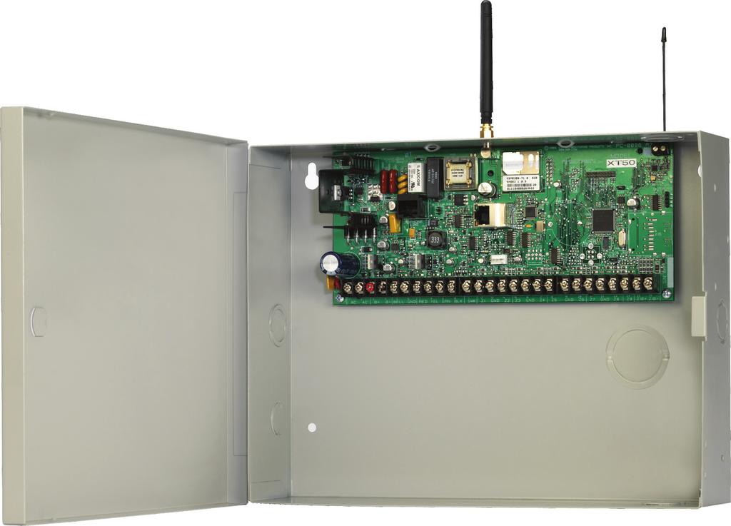
11 TX RX Wireless LEDs Installation Installation 4.1 Mounting the Enclosure The metal enclosure must be mounted in a secure, dry place to protect the panel from damage due to tampering or the elements. It is not necessary to remove the PCB when installing the enclosure. The PCB may be installed in the standard 340 mall enclosure, optional 341 Kiosk enclosure, optional 349 Medium enclosure, or the optional 349A Attack enclosure. When using cellular communication or on-board wireless with the 341 enclosure, an MA and wireless antenna eit may be added at the time of the installation. The 349A Attack Resistant enclosure is factory shipped with one knockout on the top left of the enclosure. As needed, additional knockouts may be added at the time of installation. ee Figure 3 for the positions on the enclosure that can be added. Each additional knockout must be filled with conduit. lide panel PCB into lower enclosure slots Model 349 Enclosure Enclosure Mounting Hole Panel PCB screw lide panel PCB between formed metal supports J3 Phone Line Model 340 Enclosure J19 Celllular J7 RJ upervision J1 Ethernet J8 RED Programming J24 Celllular header J20 Wireless J18 Load J J16 Reset Outputs Panel PCB screw Enclosure Mounting Hole Enclosure Mounting Hole Panel PCB screw J3 Phone Line J19 Celllular J7 RJ upervision J1 Ethernet J8 RED Programming J24 Celllular header J16 Reset J20 Wireless J11 J Load 3 4 Outputs Panel PCB screw Dual 1/2" and 3/4" Conduit Knockouts Enclosure Mounting Holes Dual 1/2" and 3/4" Conduit Knockout Enclosure Mounting Holes Battery helf Battery helf Figure 2: tandard 340 Enclosure (left), Optional 349 Enclosure (right), lide panel PCB between formed metal supports Lid Mounting Holes (4 places) Lid Mounting Holes (4 places) PEMs for optional battery bracket J3 Phone Line Power LED Dual 1/2" and 3/4" Conduit Knockouts Model 341 Enclosure J7 RJ upervision OVC LED J19 Celllular J1 Ethernet RCV J8 XMIT Programming J24 Celllular header Openings drilled at installation J16 Reset J20 Wireless (XT50 only) TX RX Wireless LEDs J18 Load Outputs Enclosure Mounting Holes (4 places) J11 J3 Phone Line Power LED J7 RJ upervision Model 349A Enclosure OVC LED J19 Celllular J1 Ethernet RCV J8 XMIT Programming Dual 1 3/4" and 1 3/8" Conduit Knockouts * 349A Optional Knockout J24 Celllular header for 263G Outputs 3-Hole Pattern for Accessory Modules * * J16 Reset J18 Load J20 Wireless (XT50 only) J11 * Front and Rear Tamper witches for 350A Attack Resistant Enclosure Tamper Mounting Holes (Upper and Lower) * Battery helf * Figure 3: Optional 341 Enclosure (left), Optional 349A Enclosure (right), 6
12 Installation 4.2 Mounting Keypads DMP keypads have removable covers that allow the base to be mounted on a wall or other flat surface using the screw holes provided on each corner. For mounting keypads on solid walls, or for applications where conduit is required, use a DMP 695 or 696 keypad conduit backbo. 4.3 Installation pecifications everal factors determine the performance characteristics of the keypad bus: the length of wire used, the number of devices connected, and the voltage at each device. When planning a keypad bus installation, keep in mind the following four specifications: 1. DMP recommends using 18 or 22-gauge unshielded wire for all keypad circuits. Do not use twisted pair or shielded wire for keypad bus data circuits. 2. On keypad bus circuits, to maintain auiliary power integrity when using 22-gauge wire do not eceed 500 feet. When using 18-gauge wire do not eceed 1,000 feet. To increase the wire length or to add devices, install an additional power supply. Note: Each panel allows a specific number of supervised keypads. Add additional keypads in the unsupervised mode. Refer to the panel installation guide for the specific number of supervised keypads allowed. 3. Maimum distance for any one bus circuit (length of wire) is 2,500 feet regardless of the wire gauge. This distance can be in the form of one long wire run or multiple branches with all wiring totaling no more than 2,500 feet. As wire distance from the panel increases, DC voltage on the wire decreases. 4. Maimum voltage drop between the panel (or auiliary power supply) and any device is 2.0 VDC. If the voltage at any device is less than the required level, add an auiliary power supply at the end of the circuit. When voltage is too low, the devices cannot operate properly. For additional information refer to the 710 Installation heet (LT-0310) and or the LX-Bus/Keypad Bus Wiring Application Note (LT-2031). Primary Power upply 5.1 AC terminals 1 and 2 Connect the transformer wires to terminals 1 and 2 on the panel. Use no more than 70 ft. of 16 gauge, or 40 ft. of 18 gauge, wire between the transformer and the panel to deliver a minimum of 15.5 VAC when 500mA of current draw is used from the auiliary power supply terminal 7. Always ground the panel before applying power to any devices: The panel must be properly grounded before connecting any devices or applying power to the panel. Proper grounding protects against Electrostatic Discharge (ED) that can damage system components. ee Earth ground, in the econdary Power upply section. 5.2 Transformer Types The transformer for the panel is 16.5 VAC 40 VA, which provides up to 1.5 Amps of bell output current, 500mA of auiliary current, and 100mA of smoke detector output. Use either the Model 320 wire-in or 321 plug-in transformer with the panel. The total current available is limited by the total battery standby requirements of the installation. The transformer must be connected to a 120 VAC 60 Hz commercial power outlet that is not con trolled by a wall switch. Never share the transformer output with any other equipment. 5.3 Power LED When either AC transformer power or DC battery power is connected to the panel the PWR LED shows steady green. 7
13 Installation 6.1 Battery Terminals 3 and 4 Connect the black battery lead to the negative battery terminal. The negative terminal connects to the enclosure ground internally through the XT30 or XT50 circuit board. Connect the red battery lead to the positive battery terminal. Observe polarity when connecting the battery. Add a second battery in parallel using the DMP Model 318 Dual Battery Harness. DMP requires each battery be separated by a PTC in the battery harness wiring to protect each battery from a reversal or short within the circuit. ee Figure 4. econdary Power upply Use sealed lead-acid batteries only: Use 12 VDC sealed lead-acid rechargeable battery. Batteries supplied by DMP have been tested to ensure proper charging with DMP products. GEL CELL BATTERIE CANNOT BE UED WITH THE XT30/XT50 PANEL. 6.2 Earth Ground Terminal 4 of the panel must be connected to earth ground using 14 gauge or larger wire to provide proper transient suppression. DMP recommends connecting to a metal cold water pipe or ground rod only. Do not connect to electrical conduit or a telephone company ground. 6.3 Replacement Period DMP recommends replacing the battery every 3 to 5 years under normal use. 6.4 Discharge/Recharge The panel battery charging circuit float charges at 13.9 VDC at a maimum current of 1.2 Amps using a 40 VA transformer. The total current available is reduced by the combined auiliary current draw from terminals 7, 11, and 25. The various battery voltage levels are listed below: Battery Trouble: Battery Restored: Below 11.9 VDC Above 12.6 VDC 318 Battery Harness 6.5 Battery upervision The panel tests the battery once every hour when AC power is present. This test occurs 15 minutes past each hour and lasts for five seconds. A load is placed on the battery and if its voltage falls below 11.9 VDC a low battery is detected. If AC power has failed, a low battery is detected any time the battery voltage falls below 11.9 VDC. If a low battery is detected with AC power present, the test is repeated every two minutes until the battery charges above 12.6 VDC; the battery restored voltage. If a faulty battery is replaced with a fully charged battery, the restored battery will not be detected until the net two-minute test is done. 6.6 XT30/XT50 Power Requirements During AC power failure, the panel and all auiliary devices connected draw their power from the battery. All devices must be taken into consideration when calculating the battery standby capacity. On the following page is a list of the power requirements of the panel. Add the additional current draw of DMP keypads, smoke detector output, and any other auiliary devices used in the system for the total current required. The total is then multiplied by the total number of standby hours required to arrive at the total Amperehours required. Battery PTC Red Black Red Black Battery To AC AC AC +B B Panel Red and Black Battery Cables Figure 4: Wiring Multiple Batteries XT30/XT50 Command Processor Panel 14 AWG to Earth Ground To Bell Circuit BELL GND 5 6 8
14 6.7 XT30/XT50 tandby Battery Calculations tandby Battery Power Calculations XT30 Panel XT50 Panel Built-in Network (additional current) Built-in Cellular (additional current) Active Zones 1-9 Active Zone 10 2-Wire moke Detectors Panel Bell Output 125mA 145mA 145mA 18mA 1.6mA 4mA 0.1mA ma Installation 1500mA Alarm Current 125mA 145mA 145mA 18mA *2mA 30mA 0.1mA Ma. ma 263G Digital Cellular Communicator 18mA 18mA 263C Digital Cellular Communicator 13mA 13mA 263H HPA+ Cellular Communicator 24mA 28mA 1100D Wireless Receiver 40mA 40mA 1100DH Wireless High Power Receiver 160mA 160mA 1100DI Wireless In-Line Receiver 30mA 30mA 7060/7160 Thinline/7060A Aqualite Keypad 72mA 87mA 7063/7163 Thinline/7063A Aqualite Keypad 85mA 100mA 7070/7170 Thinline/7070A Aqualite Keypad Active Zones (EOL Installed) 72mA 1.6mA 67mA 80mA 7073/7173 Thinline/7073A Aqualite Keypad Active Zones (EOL Installed) 85mA 1.6mA 7360 Thinline Icon Keypad 7363 Thinline Icon Keypad 60mA 73mA 67mA 80mA 7872 Graphic Touchscreen Keypad Active Zones (EOL Installed) 7873 Graphic Touchscreen Keypad Active Zones (EOL Installed) 145mA 1.6mA 143mA 1.6mA 215mA 2.0mA 243mA 2.0mA 708 Bus Etender Module (one pair) 20mA 20mA 710 Bus plitter/repeater Module 30mA 30mA 714 Zone Epansion Modules Active Zones (EOL Installed) 7mA 1.6mA 7mA *2mA Zone Epansion Module Active Zones (EOL Installed) 17mA 1.6mA 17mA *2mA 714-8, Zone Epansion Module Active Zones (EOL Installed) 20mA 1.6mA 20mA *2mA 715 Zone Epansion Module Active Zones (EOL Installed) 2-Wire mokes 7mA 4mA.1mA 7mA *30mA.1mA 715-8, Zone Epansion Modules Active Zones (EOL Installed) 2-Wire mokes 734 Wiegand Interface Module Active Zones (EOL Installed) 20mA 4mA.1mA 15mA 1.6mA 20mA *30mA.1mA 15mA *2mA 738A Ademco Wireless Interface Module 75mA 75mA 738Z Z-Wave Interface Module 32mA 47mA Au. Powered Devices on Terminals 7 and 11 ma ma Other than Keypads and Modules Total tandby ma Total tandby ma number of tandby Hours = needed ma Total Alarm ma ma-hours ma-hours Total Alarm + ma-hours Total X.001 * Based on 10% of active zones in alarm condition. = Amp-hrs Required 9
15 Installation Bell Output 7.1 Terminals 5 and 6 Nominal 12 VDC is supplied by terminal 5 on the panel to power alarm bells or horns. The output is rated for a maimum of 1.5 Amps with a 40 VA transformer. This output can be steady, pulsed, or Temporal Code 3 depending upon the Bell Action specified in Output Options programming. Terminal 6 is the ground reference for the bell circuit. If using a horn or siren, a 1k 0hm resister should be added across the bell circuit for supervision. Keypad Data Bus 8.1 Description Terminals 7, 8, 9, and 10 of the panel are designated as the keypad data bus. In addition to keypads, the XT30/XT50 allows the of any combination of zone epansion modules, 5845LX Glassbreak Detectors, and 6155LX PIRs to the keypad bus up to the maimum of eight devices. 8.2 Terminal 7 - RED Nominal 12 VDC is supplied at terminal 7 to power keypads and zone epanders. This is also where power for any auiliary device is supplied. The ground reference for terminal 7 is terminal 10. The maimum output is rated at 500mA. All auiliary devices totaled together must not eceed the Terminal 7 maimum current rating of 500mA. When the number of keypads or other epansion devices attached eceeds the amount of output current available, attach an eternal power supply as defined in the Model 710 Installation heet (LT-0310). 8.3 Terminal 8 - YELLOW Data receive from keypads and zone epanders. 8.4 Terminal 9 - GREEN Data transmit to keypads and zone epanders. 8.5 Terminal 10 - BLACK Terminal 10 is the ground reference for LCD keypads, zone epanders, and any auiliary devices being powered by terminals 7 and Keypad Bus LEDs The two LEDs located just above terminal 13 indicate keypad transmit data (XMIT) and keypad receive data (RCV). The bottom LED flashes green to indicate data being transmitted from the panel. The top LED flashes yellow to indicate data being received by the panel from keypads, zone epanders, etc. 8.7 Programming Connection A locking 4-pin header (J8) is provided to connect a keypad when using a DMP Model 330 Programming Cable. This provides a quick and easy for programming the panel. 8.8 Keypad Addressing Keypad Bus epansion zones are numbered in groups of four corresponding to the address. Eample: address 1 is zones and address 5 is zones There are a maimum of 32 zones possible on the Keypad Bus. All keypad zones terminate with a 1k 0hm EOL resister. Address XT30/XT50 Zone Number
16 8.9 Overcurrent OVC LED The Overcurrent LED (OVC) lights Red when the devices connected to the Keypad Bus draw more current than the auiliary output rating. The OVC LED is located above terminals 9 and 10 as shown in Figure 4. When the OVC LED lights Red, the Keypad bus/auiliary power (terminal 7) and the Programming header (J8) shut down. moke and Glassbreak Detector Output 9.1 Terminal 11 Nominal 12 VDC at 100mA maimum (shared by terminal 25) is supplied at terminal 11 to power 4-wire smoke detectors or other auiliary powered devices. This output can be turned off by the user for 5 seconds using the ensor Reset option in the User Menu. Terminal 10 is the ground reference for terminal 11. Installation J3 Phone Line Power LED J7 RJ upervision OVC LED Figure 5: OVC LED location Burglary Zones 10.1 Description On XT30/XT50 panels, terminals 12 to 24 are the nine burglary zones. For programming purposes, the zone numbers are 1 to 9. The zone configurations on terminals 12 to 24 are described below. Terminal Function Terminal Function 12 Zone 1 voltage sensing 19 Ground for zones 5 & 6 13 Ground for zones 1 & 2 20 Zone 6 voltage sensing 14 Zone 2 voltage sensing 21 Zone 7 voltage sensing 15 Zone 3 voltage sensing 22 Ground for zones 7, 8, & 9 16 Ground for zones 3 & 4 23 Zone 8 voltage sensing 17 Zone 4 voltage sensing 24 Zone 9 voltage sensing 18 Zone 5 voltage sensing The voltage sensing terminal measures the voltage across the 1k Ohm End-of-Line resistor and the zone s ground terminal. Dry contact sensing devices can be used in series (normally-closed) or in parallel (normallyopen) with any of the burglary protection zones Operational Parameters Each burglary protection zone detects three conditions: open, normal, and short. The parameters for each are listed below: Condition Resistance on zone Voltage on zone terminal Open over 1300 ohms over 2.0 VDC Normal 600 to 1300 ohms 1.2 to 2.0 VDC hort under 600 ohms under 1.2 VDC 1K Ohm Normally Closed 1K Ohm Normally Open 1K Ohm Combination Normally Open and Normally Closed Figure 6: Protection Zone Contact Wiring 11
17 Installation 10.3 Zone Response Time A condition must be present on a zone for 500 milliseconds before it is detected by the panel. Ensure detection devices used on the protec tion zones are rated for use with this delay Keyswitch Arming Zone You can use a momentary keyswitch on a zone programmed as an Arming type for use in arming and disarming the system without a code. Powered Zone for 2-Wire moke Detectors 11.1 Terminals 25 and 26 A resettable 2-wire Class B powered zone is provided on terminals 25 (positive) and 26 (negative) of the panel. For programming purposes, the zone number is 10 on the XT30/XT50. The zone uses a Model 309, 3.3k Ohm EOL resistor (provided with the panel) and has an operating range of 8.8 to 13.9 VDC. The compatibility identifier is: B Caution: ensor reset on zone 10 drops power to devices on this zone, causing the panel to sense an open condition on all zone types other than Fire, Fire Verify, and upervisory. Whenever non-fire and non- upervisory zone types are used on zone 10, make the appropriate adjustments to the zone s Armed Action to prevent false alarms from occurring. Manufacturer Model Detector ID # of Detectors Zone Epansion Modules DMP/Hochiki LR-835B HD , 715-8, , 725 entrol/el 429AT, 521B, 521BXT 09A , 715-8, ystem ensor 2WTA-B, 2WTR-B A , 715-8, Annunciator Outputs 12.1 Description The four annunciator outputs can be programmed to indicate the activity of the panel s zones or conditions occurring on the system. Annunciator outputs do not provide a voltage but instead switch-to-ground voltage from another source. The outputs can respond to any of the conditions listed below: 1) Activation by zone condition: teady, Pulse, Momentary, or Follower 6) Ambush alarm 2) Manually from the keypad 7) Eit and Entry timers 3) Communication failure 8) ystem Ready 4) Armed area annunciation 9) Late to Close 5) Fire Alarm or Fire Trouble 12.2 Harness Wiring The open collector outputs are accessible by installing the DMP 300 Harness on the 4-pin header labeled J11. The output locations are shown below. For listed applications, devices connected to outputs must be located within the same room as the panel. Output Color Wire Output Color Wire 1 Red 1 3 Green 3 2 Yellow 2 4 Black Model 860 Relay Module Connect a Model 860 Relay Module to the panel to provide relays for the annunciator outputs that can be used for electrical isolation between the alarm panel and other systems or for switching voltage to control various functions. The module includes one relay and provides three additional sockets for epansion of up to four relays. Power is supplied to the relay coils from the panel keypad bus. The 860 mounts inside the panel enclosure using the 3-hole mounting configuration. Plastic standoffs are provided with the module for ease of installation. A 4-wire harness is also provided that connects the Model 860 to the panel. Relay Contact Rating: 1 Amp at 30 VDC 12
18 Telephone RJ Connector Installation 13.1 Description Connect the panel to the public telephone network by installing a DMP 356 RJ Cable between the panel s J3 connector and the RJ31X or RJ38X phone jack. CAUTION - To reduce the risk of fire, use only No. 26 AWG or larger telecommunication line cord, such as DMP Model 356 eries Phone Cords. A two pin header labeled RJ UP (J7) is provided to allow monitoring of the telephone cable connected between the panel and a RJ38X jack (pins 2 and 7 jumpered). Attach a DMP Model 306 Harness between J7 and any available zone. The J7 pins are connected via the telephone cable to the RJ38X jack pins 2 and 7. The RJ38X jack provides a jumper between pins 2 and 7 which completes the circuit. Program the zone as a upervisory type (V). When the telephone cable is removed, the keypad displays zone trouble and produces a steady tone. To Telephone Line Ring Tip 2 1 RJ31X or RJ38X Phone Block To Premise Phone(s) Ring 1 Tip 1 Figure 7: Phone Jack Wiring 13.2 FCC Registration The panel complies with FCC part 68 and is registered with the FCC. Registration number: CCKAL00BXT50 Ringer Equivalence: 0.0B 13.3 Notification Registered terminal equipment must not be repaired by the user. In case of trouble, the device must be immediately unplugged from the telephone jack. The factory warranty provides for repairs. Registered terminal equipment may not be used on party lines or in with coin telephones. No tification must be given to the telephone company with the following information: a. The particular line(s) the service is connected to b. The FCC registration number c. The ringer equivalence d. The make, model, and serial number of the device Ethernet Connector J Description The Ethernet Connector (J1) is available on the Network version and connects directly to an Ethernet network using a standard patch cable Ethernet LEDs The two LEDs, located on the left side of the J1 Ethernet Connector, indicate network operation. The top, Link LED is a steady green light when an ethernet cable is connected. The bottom, Activity LED flashes yellow to indicate messages are being received or transmitted. 13
19 Installation Reset Header J Description The reset header is located just above the terminal strip on the right side of the circuit board and is used to reset the XT30/XT50 microprocessor. To reset the panel when first installing the system, install the reset jumper before applying power to the panel. After connecting the AC and battery, remove the reset jumper. To reset the panel while the system is operational, for eample, prior to reprogramming, install the reset jumper without powering down the system. Remove the reset jumper after one or two seconds. After resetting the panel, begin programming within 30 minutes. If you wait longer than 30 minutes, reset the panel again. XT30/XT50 Panel J19 Celllular J24 Celllular header J20 Wireless J3 Phone Line Power LED J7 RJ upervision OVC LED J1 Ethernet RCV J8 XMIT Programming Momentarily place the Reset jumper over both of the J16 pins to reset the panel. J16 Reset TX RX Wireless LEDs J18 Load J Outputs Figure 8: Panel howing the Reset Jumper Wires 14
20 Installation Flash Load Jumper J Description The XT eries panel software can be updated via the panel s programming (PROG) header. To update the XT30/50 panel with a new software version, complete the following steps at the protected premise: 1. Place a jumper across the Reset (J16) header and then remove the yellow and green wires from keypad bus terminals 8 and Connect a DMP 399 Cable from the J8 Programming Header to the serial port of your PC operating Remote Link and containing the XT RU file. Requires Remote Link 1.43 or higher. 3. tart Remote Link and create or open the XT eries control panel account that matches the panel to be updated. 4. et the Connection Information Type to Direct with a baud rate of and choose the appropriate COM port. 5. elect Panel>Remote Update, then select the correct RU file for the XT panel model. 6. While placing a short across the LOAD (J18) header, remove the jumper from the Reset (J16) header. Click <Update> in Remote Link. 7. After the software version is updated, remove the short from the LOAD header. Place the jumper across Reset (J16) then remove the 399 cable. 8. Replace the yellow and green wires to terminals 8 and Remove Reset (J16) jumper to resume normal panel operation. Cellular Connections 17.1 Cellular The XT30/XT50 Cellular option is available built-in at the factory or as an optional add-on module, Model 263G, Model 263H, or Model 263C. The J19 MA cellular antenna connector is provided for the built-in cellular version and protrudes through the top of the enclosure. If the panel is not purchased with built-in cellular, then the J24 header is provided to connect a 263G Digital Cellular Communicator, 263C CDMA Cellular Communicator, or 263H HPA+ Cellular Communicator as an addon. The cellular antenna protrudes through the top of the enclosure. Brass Washer 1100 eries (XT50) J19 Celllular connector J24 Celllular header J eries Wireless Wireless LEDs J1 Ethernet Built-in Cellular Module J18 Load TX RX J11 Outputs RCV J8 XMIT Programming J16 Reset Figure 9: Cellular and 1100 eries Wireless Connections 15
21 COMPLIANCE On-Board 1100 eries Wireless Connection 18.1 Wireless The XT50 Wireless terminal block J20 is located at the top right corner of the circuit board. The antenna installs through a small opening in the top of the enclosure and is attached to the panel using the right terminal. The left terminal is not used. The XT50 built-in wireless operates with DMP 1100 eries transmitters. ee section 3.4 for a list of accessory devices LED Operation Green (TX): With a wireless house code enabled, the green LED flashes every time the receiver transmits (32 times per second). If a house code is not programmed in the panel, the panel is reset, or the panel is powered off, the green LED will be off. Under normal operation, the green LED flashes constantly with no interruption or change. Yellow (RX): The yellow LED flashes every time the receiver hears a message from a programmed wireless transmitter. When a message is sent by a transmitter, typically by pressing or releasing the tamper switch, the yellow LED should flash indicating that the receiver received a message from the transmitter. If the LED never flashes, the transmitter is not getting through to the receiver. This could be because of a misprogrammed serial number or the transmitter is too far away. Under normal operation, the yellow LED will flash at every trip of every wireless transmitter and occasionally when the transmitters perform their periodic check-in. It is not unusual for this LED to stay off for many minutes at a time when no transmitters are communicating. Wireless Keypads 19.1 Mounting Keypads DMP keypads have removable covers that allow the base to be mounted on a wall, desk stand or other flat surface using the screw holes provided on each corner Wireless Keypad Association Enable Wireless Keypad Association operation on both the keypad and panel. To enable association operation in the keypad, access the Installer Options Programming Menu (3577 (INT)) and select RF urvey). The keypad logo LEDs turn on Red until association is successful. To enable association operation in the XT30/XT50 panel, reset panel 3 times within 12 seconds. Allow the keypad bus Transmit/Receive LEDs to turn back on between each reset. For 60 seconds the panel listens for wireless keypads that are in the Installer Options Menu (3577 CMD) and have not been programmed, or associated into another panel. Those keypads are assigned to the first open device position automatically based upon the order in which they are detected. The keypad logo turns Green to indicate it has been associated with the panel. RCV XMIT J8 16
22 COMPLIANCE Listed Compliance pecifications 20.1 Introduction The programming and installation specifications contained in this section must be completed when installing the XT30/XT50 in accordance with any of the ANI/UL burglary standards. Additional specifications may be required by a particular standard Bypass Reports The bypass reports must be programmed as YE for all listed burglary applications Current Draw The total current draw from a combination of auiliary, smoke, and bell output terminals must not eceed 1.6 Amps Battery tandby Use battery Models 365 (12 VDC 9Ah) or 366 (12 VDC 18Ah) with the XT30/XT50 panel when installed in the 340, 341, 349, or 349A enclosures. The Model 364 (12 VDC 1.3Ah) battery is for use with the XT30/XT50 panel when using the 341 enclosure with the optional 341B Battery Bracket. The Model 364 battery is rated for 4 hours of standby time Auiliary and Bell Current For UL listed applications, the maimum auiliary current is 400mA, and the maimum bell current is 500mA Cross Zoning Each zone must have the capability of protecting the common area individually oftware Version For UL listed applications, the minimum software version must be Version App Key The Remote Option App Key has not been evaluated for use in listed applications. Household Burglar-Alarm ystem Units ANI/UL Bell Cutoff The bell cutoff time cannot be less than four minutes Entry Delay The maimum entry delay used must not be more than 45 seconds Eit Delay The maimum eit delay used must not be more than 60 seconds Wireless Eternal Contact When used, the Eternal Contact of 1101, 1102 or 1105 must be programmed Normally Closed Wireless upervision Time The Zone Information upervision Time cannot be set to 0 (zero) Wireless Audible Annunciation The Wireless Audible option must be selected as DAY for residential applications Panel location Mount panel inside protected area Test Frequency The Test Frequency option must be programmed to send a report at least once every 30 days. Digital Burglar Alarm Communicator ystem Units ANI/UL Entry Delay The maimum entry delay used must not be more than 60 seconds Eit Delay The maimum eit delay used must not be more than 60 seconds Test Frequency The Test Frequency option must be programmed to send a report once every 24 hours Automatic Bell Test This option must be programmed as YE. 17
23 COMPLIANCE Central tation Burglar Alarm Units ANI/UL Central tation Digital Dialer Central tation (DACT) service for commercial application can be provided by adding a listed local audible signal appliance and placing the XT30 or XT50 panel into the Model 349A Attack Resistant Enclosure Remote Disarm REMOTE DIARM must be programmed as NO Central tation MEAGE TO TRANMIT programming for zones must not be set to LOCAL (L). Household Fire Warning ystem ANI/UL 985 NFPA 72 pecifications 24.1 Bell Output Definition The bell output of the Model XT30/XT50 must be programmed to operate steady on burglary alarms and temporal on fire alarms. ee the XT30/XT50 Programming Guide Household ystem An alarm sounding device must be installed indoors so that it is clearly heard in all sleeping areas Household Fire Warning Recognized limited energy cable must be used for of all initiating, indicating, and supplementary devices Wireless upervision Time The Zone Information upervision Time must be 3 minutes for fire devices. ee the XT30/XT50 Programming Guide Wireless Fire Verification When used, the Model 1161 and 1162 wireless smoke detectors must not be programmed as Fire Verification (FV) zone type. ee the XT30/XT50 Programming Guide Battery tandby For UL listed applications, the panel must have 24 Hour battery standby operation. The Model 364 battery should not be used for fire installations Alarm Verification Alarm Verification must only be enabled on smoke detectors that do not employ an integral alarm verification feature Model 860 When using the Model 860 Relay Output, a fire and non-fire device must not share a relay Test Frequency The Test Frequency option must be programmed to send a report at least once every 30 days. California tate Fire Marshal pecifications 25.1 Bell Output Definition The bell output of the Model XT30/XT50 must be programmed to operate steady on burglary alarms and temporal on fire alarms. 18
24 False Alarm Reduction Programmable Options ANI/IA CP hipping Defaults and Recommended Programming IA CP-01 FEATURE PARAGRAPH # AND DECRIPTION DMP PROGRAMMING GUIDE LT 0981 ECTION # Eit Time 8.6 Eit Delay Progress Annunciation Prewarn Address Allowed REQUIREMENT Required (Programmable) Eit Time Restart 8.6 Eit Delay Required Option Auto tay Arm on Unvacated Premises Eit Time and Progress Annunciation/ Disable - for Remote Arm 8.17 Occupied Premise - ee Install Guide Not Available on Remote Arming Entry Delay(s) 8.5 Entry Delay Abort Window for Non Fire Zones Abort Window Time for Non-Fire Zones Abort Annunciation Cancel Annunciation & Duress Feature Required Option (ecept for remote arming) Allowed Option Required (Programmable) 3.3 Transmit Delay Required Option 3.3 Transmit Delay Required (Programmable) 3.3 Transmit Delay Required Option Always Enabled - Not Programmable User Code + 1 = Ambush Code Not Available Required Option Allowed Option Cross Zoning Cross Zone Required Option Programmable Cross Zoning Time winger hutdown winger hutdown Disable Fire Alarm Verification 4.5 Call Waiting Cancel RANGE 45 sec sec. Individual keypads may be disabled per zone For re-entry during eit time Occupied Premise NO/ YE option Progress Annunciation Always disabled for Remote Arming 30 sec. 240 ec. ** Disable by zone or zone type 20 sec., 30 sec., or 40 sec. ** Annunciate that no alarm was transmitted Yes Annunciate that a Cancel was transmitted (49) No 1 + derivative of another user code/no duplicates with other user codes Yes/No Zone Programming COMPLIANCE HIPPING DEFAULT 60 econds All keypads enabled Enabled Enabled Not Available 30 econds Enabled NT DY EX Zone 30 econds Always Enabled Code +1 Always Disabled 8.7 Cross Zone Time Allowed 4 sec sec. 0 econds Not Available Always On winger Bypass Allowed No RECOMMENDED PROGRAMMING* 60 econds All keypads enabled Enabled Enabled Yes for Residential Applications Remote Arming not allowed for CP-01 installations. At least 30 econds ** Enabled At least 20 econds ** Yes Yes Required 1-6 trips 2 trips 2 trips For non-police response zones 13.5 Zone Type Required Option FV Type Zone No 3.17 First Telephone Number Required Option ystem Test 17.5 Walk Test Allowed Include *70P in Telephone Number Test all protection Yes Disabled devices Communications 17.5 Walk Test Not Allowed N/A N/A N/A * Programming at installation may be subordinate to other listed requirements for the intended application. ** For listed Installations, combined Entry Delay and Transmit Delay should not eceed 1 minute. N/A Not Programmable Enabled using two or more programmed zones Per walk path in protected premises Enabled (all zones) Yes as required (unless sensors can self verify) Enabled if user has call waiting N/A 19
InstallatIon GuIde Xt series Panels
 Installation Guide XT eries Panels MODEL XT30/XT50 XT ERIE INTALLATION GUIDE FCC NOTICE This equipment has been tested and found to comply with the limits for a Class B digital device, pursuant to part
INSTALLATION GUIDE XT SERIES PANELS
 INTALLATION GUIDE XT ERIE PANEL FCC NOTICE MODEL XT30/XT50 XT ERIE INTALLATION GUIDE This equipment has been tested and found to comply with the limits for a Class B digital device, pursuant to part 15
INSTALLATION GUIDE XTLN-WIFI PANEL
 INSTALLATION GUIDE XTLN-WIFI PANEL MODEL XTLN-WiFi INSTALLATION GUIDE FCC NOTICE This equipment has been tested and found to comply with the limits for a Class B digital device, pursuant to part 15 of
INSTALLATION GUIDE XT30INT SERIES CONTROL PANEL
 INSTALLATION GUIDE XT30INT SERIES CONTROL PANEL MODEL XT30INT CONTROL PANEL INSTALLATION GUIDE 2018, Inc. Information furnished by DMP is believed to be accurate and reliable. This information is subject
InstallatIon GuIde XR100 series canadian control Panel
 Installation Guide XR100 eries canadian Control Panel MODEL XR100 ERIE CANADIAN CONTROL PANEL INTALLATION GUIDE INDUTRY CANADA NOTICE This Class A digital apparatus complies with Canadian ICE-003. 2015,
INSTALLATION GUIDE XR100 SERIES CONTROL PANEL
 INTALLATION GUIDE XR100 ERIE CONTROL PANEL MODEL XR100 ERIE CONTROL PANEL INTALLATION GUIDE FCC NOTICE This equipment generates and uses radio frequency energy and, if not installed and used properly in
XTLC PANEL INSTALLATION GUIDE
 XTLC PANEL INSTALLATION GUIDE MODEL XTLC INSTALLATION GUIDE FCC NOTICE This equipment has been tested and found to comply with the limits for a Class B digital device, pursuant to part 15 of the FCC Rules.
INSTALLATION GUIDE XR100 SERIES COMMAND PROCESSOR PANEL
 INSTALLATION GUIDE XR100 SERIES COMMAND PROCESSOR PANEL MODEL XR100 SERIES ACCESS CONTROL COMMAND PROCESSOR PANEL INSTALLATION GUIDE Contains installation instructions for use with the Model XR100 and
Installation Guide. XRSuper6 / XR20 / XR40
 Installation Guide XRSuper6 / XR20 / XR40 Command Processor Panels MODEL XRSuper6/XR20/XR40 COMMAND PROCESSOR INSTALLATION GUIDE FCC NOTICE This equipment generates and uses radio frequency energy and,
InstallatIon GuIde XR500FC series Command PRoCessoR Panel
 Installation Guide XR500FC eries Command Processor Panel MODEL XR500FC, XR500NFC COMMAND PROCEOR INTALLATION GUIDE FCC NOTICE This equipment generates and uses radio frequency energy and, if not installed
INSTALLATION GUIDE XR500 SERIES CONTROL PANEL
 INTALLATION GUIDE XR500 ERIE CONTROL PANEL MODEL XR500, XR500N, XR500E ERIE CONTROL PANEL INTALLATION GUIDE FCC NOTICE This equipment generates and uses radio frequency energy and, if not installed and
InstallatIon GuIde XR150fc/XR550fc series Panel
 Installation Guide XR150fc/r550FC Series Panel MODEL XR150FC/XR550FC SERIES PANEL INSTALLATION GUIDE FCC NOTICE This equipment generates and uses radio frequency energy and, if not installed and used properly
INSTALLATION GUIDE XR150/XR550 SERIES CONTROL PANEL
 GUIDE XR150/XR550 SERIES CONTROL PANEL MODEL XR150/XR550 SERIES INSTALLATION GUIDE FCC NOTICE This equipment generates and uses radio frequency energy and, if not installed and used properly in strict
InstallatIon GuIde XR500 series CanadIan ContRol Panel
 Installation Guide XR500 Series CANADIAn control Panel MODEL XR500, XR500N, XR500E CANADIAN INSTALLATION GUIDE INDUSTRY CANADA NOTICE This Class A digital apparatus complies with Canadian ICES-003. 2015,
InstallatIon GuIde XR2500F addressable FIRe alarm ContRol Panel
 Installation Guide XR2500F ADDREABLE FIRE ALARM CONTROL Panel MODEL XR2500F COMMAND PROCEOR INTALLATION GUIDE FCC NOTICE This equipment generates and uses radio frequency energy and, if not installed and
XR10/XR20 Command Processor Panels Installation Guide
 XR10/XR20 Command Processor Panels Installation Guide 10/26 Zone Burglary/Fire/Access Control Panels with Built-in Communicator LT-0229 (5/97) MODEL XR10/XR20 COMMAND PROCESSOR INSTALLATION GUIDE FCC NOTICE
XRSuper6/XR20/XR40 Command Processor TM Panels Installation Guide
 XRuper6/XR20/XR40 Command Processor TM Panels Guide 22/26/42 Zone Burglary/Fire/Access Control Panels with Built-in Communicator 2500 N. Partnership Boulevard pringfield, MO 65803 www.dmpnet.com Digital
Installation Guide. XR5FC and XR5SL
 Installation Guide XR5FC and XR5L Commercial Fire Panels MODEL XR5FC/XR5L COMMAND PROCEOR INTALLATION GUIDE FCC NOTICE This equipment generates and uses radio frequency energy and, if not installed and
INSTALLATION GUIDE XR5FC AND XR5SL COMMERCIAL FIRE PANELS
 INSTALLATION GUIDE XR5FC AND XR5SL COMMERCIAL FIRE PANELS MODEL XR5FC/XR5SL COMMAND PROCESSOR INSTALLATION GUIDE FCC NOTICE This equipment generates and uses radio frequency energy and, if not installed
PFC-7500/PFC-7501 Installation Manual
 PFC-7500/PFC-7501 Installation Manual Fire Alarm Communicator (All specifications subject to revision.) 5757 Phantom Dr. te 125 P.O. Box 42037 t. Louis, MO 63042 (866) 240-1870 (314) 595-6900 FAX (800)
INSTALLATION GUIDE XR ZONE COMMAND PROCESSOR PANEL
 INTALLATION GUIDE XR200 242-ZONE COMMAND PROCEOR PANEL MODEL XR200 COMMAND PROCEOR INTALLATION GUIDE FCC NOTICE This equipment generates and uses radio frequency energy and, if not installed and used properly
EVO192 v3.0 Fire and Burglary What s New
 EVO192 v3.0 Fire and Burglary What s New Compatibility: EVO192 v3.0 TM50 v1.31 K641 v2.41 Overview: CP-01 Compliancy Wiring Diagram The following sections/options have been added to the EVO192 panel. They
One panel offers everything you want built-in
 XT Series Z-Wave Compatible Digital Dialer GPRS Cell Modem One panel offers everything you want built-in Two-way Wireless Receiver, along with Network, Cellular, and Dialer Communications 10/100 Network
INSTALLATION GUIDE XR2400F ADDRESSABLE FIRE ALARM CONTROL PANEL
 INTALLATION GUIDE XR2400F ADDREABLE FIRE ALARM CONTROL PANEL MODEL XR2400F Addressable Fire Alarm Control Panel INTALLATION GUIDE FCC NOTICE This equipment generates and uses radio frequency energy and,
Model 17A00 Expansion Enclosure
 HOME AUTOMATION, INC. Model 17A00 Expansion Enclosure Installation Manual Document Number 17I00-1 Rev A March, 2002 Home Automation, Inc. Model 17A00 Expansion Enclosure Installation Manual Document Number
D2412 Control / Communicator Installation Manual
 D2412 Control / Communicator Installation Manual C Notice The material and instructions covered in this manual have been carefully checked for accuracy and are presumed to be reliable. However, Radionics,
1126 Series Ceiling Mount PIR Motion Detector
 Installation Sheet 1126 Series Ceiling Mount PIR Motion Detector Description The 1126 Series PIR (Passive Infrared) Motion Detectors are a compact wireless PIR. The 1126 Series offer 360, Wide Angle, or
Installation Guide. Control/Communicator
 Installation Guide Control/Communicator 33120G Page 2 Copyright 2001 Radionics Contents 1.0 Introduction... 5 1.1 Listings and Approvals... 5 1.1.1 Fire... 5 1.1.2 Burglary... 5 1.2 FCC Notice... 5 1.2.1
Independent Zone Control (I.Z.C.)
") Operation and Installation Guide Independent Zone Control (I.Z.C.) DELAYED INSTANT ARMED 1 2 3 4 7 5 6 8 9 * * fi Radionics R D279A Operation & Installation Guide 46456B Page 2 Copyright 2000 Radionics
Operation and Installation Guide Independent Zone Control (I.Z.C.) DELAYED INSTANT ARMED 1 2 3 4 7 5 6 8 9 * * fi Radionics R D279A Operation & Installation Guide 46456B Page 2 Copyright 2000 Radionics
XT30/XT50 PROGRAMMING PART 2. Slide 1. Slide 2. Slide 3. Objectives. XT30/XT50 Basic Training Programming- Part 2. Bell Options
 Slide 1 XT30/XT50 Basic Training Programming- Part 2 Slide 2 Objectives After completing this course you will: 1) Understand how to prepare the panel for programming and how to access the built-in programmer.
1100D Wireless Receiver
 00D Wireless Receiver INSTALLATION GUIDE Description The 00D Wireless Receiver provides up to 32 wireless zones for XT30/XT50 Series panels with Version 02 or higher. The 00D provides two-way, supervised
XRSuper6. User s Guide
 XRSuper6 User s Guide Silencing an Alarm All/Perimeter and Home/Away Systems While the alarm bell or siren is sounding, enter your user code. DISARM SILENCE. Select SILENCE to stop the bell or siren. This
All-In-One Wireless Security System V3.2 Programming Guide. Model # MG6130 / MG6160
 All-In-One Wireless Security System V3.2 Programming Guide Model # MG6130 / MG6160 We hope this product performs to your complete satisfaction. Should you have any questions or comments, please visit www.paradox.com
1100X Wireless Receivers
 00X Wireless Receivers INSTALLATION GUIDE Description The 00X Wireless Receiver is compatible with all DMP wireless devices. The receiver provides two-way, supervised communication using 900 MHz frequency
SHORT CIRCUIT ISOLATOR TO NEXT COMPONENT REQUIRING POWER TO NEXT KEYPAD (** IF REQUIRED) STROBE RELAY MODULE KEYSWITCH ISOLATION MODULE STROBE
 STROBE RELAY MODULE KEYSWITCH ISOLATION MODULE STROBE") The Door Switch 11772 Westline Industrial Drive St. Louis, Mo 63146 (877) 998-5625 www.thedoorswitch.com Patent No. RE42,991 and RE44,039 CONTROL PANEL TRANSFORMER (SUPPLIED WITH CONTROL PANEL) NOTIFICATION
The Door Switch 11772 Westline Industrial Drive St. Louis, Mo 63146 (877) 998-5625 www.thedoorswitch.com Patent No. RE42,991 and RE44,039 CONTROL PANEL TRANSFORMER (SUPPLIED WITH CONTROL PANEL) NOTIFICATION
Fire Control/Communicator
 Operation and Installation Manual Fire Control/Communicator 1 2 3 4 5 12V AC,20V A, 60Hz or +24V DC 12V AC, 20V A, 60Hz or -24V DC EARTH GND BATTERY - BATTERY + 6 INITIATING A1-7 INITIATING A2-8 INITIATING
OJD ITB No Attachment E Duress Alarm Equipment Specifications
 Duress Alarm Equipment Specifications PART 1 GENERAL 1.1 SECTION INCLUDES A. Duress devices. B. Alarm control panel. C. Signaling devices. 1.2 REFERENCE STANDARDS A. NFPA 70 - National Electrical Code;
XR200 Command Processor Panel Installation Guide
 XR200 Comm Processor Panel Installation Guide 242 Zone Burglary/Fire/Access Control Panel with Built-in Communicar 2841 E. Industrial Drive pringfield, MO 65802-6310 LT-0197 (2/97) MODEL XR200 COMMAND
Addressable Fire Alarm Control Panel
 PRODUCT SPECIFICATION XR2400F Addressable FACP Addressable Fire Alarm Control Panel Description The DMP XR2400F Addressable Fire Alarm Control Panel is an expandable Fire Alarm Control with built-in DACT
FIRE DETECTION SYSTEM SPECIFICATION FOR MODEL XR200
 FIRE DETECTION SYSTEM SPECIFICATION FOR MODEL XR200 1.0 General 1.1 Manufacturer Manufacturer of the Fire Alarm Control Panel (FACP) equipment shall be: Digital Monitoring Products, Incorporated 2500 N.
D2212 Control/Communicator Installation Manual
 D2212 Control/Communicator Installation Manual 15-16 Radionics Notice The material and instructions covered in this manual have been carefully checked for accuracy and are presumed to be reliable. However,
The most affordable codeless arming and disarming available with a slim new look!
 The most affordable codeless arming and disarming available with a slim new look! 7000 Series Thinline LCD Keypads offer high- quality, cost-effective security control in a stylish, sleek new design. Visual
Silencing an Alarm All/Perimeter or Home/Sleep/Away System What to do when a trouble tone is sounding
 Silencing an Alarm When the alarm bell or siren is sounding, enter your user code or present your card to a keypad or reader during the Status List display. All/Perimeter or Home/Sleep/Away System CANCEL
Control Panels. Control Panels for Commercial Applications. Control panels provide the central processing
 Control Panels Control Panels for Commercial Applications Control panels provide the central processing and logic for an integrated system. In a typical system, there are four major functions: inputs,
Silencing an Alarm All/Perimeter or Home/Sleep/Away System What to do when a trouble tone is sounding
 Silencing an Alarm When the alarm bell or siren is sounding, enter your user code or present your card to a keypad or reader during the Status List display. All/Perimeter or Home/Sleep/Away System CANCEL
RANGER 8600 DOWNLOADABLE CONTROL COMMUNICATOR INSTALLATION MANUAL
 RANGER 8600 DOWNLOADABLE CONTROL COMMUNICATOR INSTALLATION MANUAL TABLE OF CONTENTS GENERAL DESCRIPTION... 2 STANDARD AND OPTIONAL PARTS LIST... 2 PARTS DIAGRAM... 3 TERMINAL DRAWING AND SPECIAL NOTES...
SPEC SHEET. Simple Expansion Solutions ZONE EXPANSION MODULES: SINGLE AND MULTIPLE POINT
 SPEC SHEET Simple Expansion Solutions Expand your DMP panel options with a wide array of expansion modules. Add supervised Class B burglary zones. Connect non-powered burglary or fire type devices for
Supervised Security System Owner's Guide
 Owner's Guide PSC06 READ THIS FIRST This equipment generates and uses radio frequency energy, and if not installed and used properly, that is, in strict accordance with the manufacturers instructions,
DS7400Xi Addressable Control/ Communicator
 DS7400Xi Addressable Control/ Communicator DS7400Xi DS7400Xi-EXP 110VAC operation 220VAC operation Remotely Programmable WDSRP (Windows Detection Systems Remote Programming Software), allows the systems
Fire Burglary Instruments Inc. XL-2G Gold Control/Communicator Installation Training Seminar Rev. 5/96
 Fire Burglary Instruments Inc. XL-2G Gold Control/Communicator Installation Training Seminar Rev. 5/96 XL-2G Gold Product Overview 7 Zones (6 programmable + panic or keyswitch zone) Fast Loop Response
XT30/XT50 U S E R G U I D E
 XT30/XT50 USER GUIDE Silencing an Alarm When the alarm bell or siren is sounding, enter your user code or present your card to a keypad or reader during the Status List display. All/Perimeter or Home/Sleep/Away
1125 PIR Motion Detector
 Tamper Survey LED INSTALLATION SHEET 1125 PIR Motion Detector Description The 1125 PIR (Passive Infrared) Motion Detector is a wireless, low current sensor for use with the 1100D Wireless Receiver. Using
NX-4V2 Control Panel Installation Instructions
 4V2 Control Panel Installation Instructions Introduction This is the 4V2-Control Panel Installation Instructions. Installations should only be done by trained professionals. Use this document to install
AdvisorOne Quick Operation Guide
 AdvisorOne Quick Operation Guide EN CNF ES PR English: Quick Operation Guide Introduction AdvisorOne (part # AVO-1037) is a wireless, self-contained system used to detect, control and inform of security
INSTALLATION AND PROGRAMMING GUIDE. XTLplus SERIES PANELS
 ITALLATIO AD PROGRAMMIG GUIDE XTLplus ERIE PAEL MODEL XTLplus ERIE ITALLATIO AD PROGRAMMIG GUIDE FCC OTICE This equipment has been tested and found to comply with the limits for a Class B digital device,
Installation Instructions
 g 466-2339A October 2009 2009 GE Security, Inc. Introduction This is the GE. Installations should only be done by trained professionals. Use this document to install the system with default settings that
Silencing an Alarm Note: Area Systems What to do when a trouble tone is sounding
 Silencing an Alarm When the alarm bell or siren is sounding, enter your user code or present your card to a keypad or reader during the Status List display. IS THIS A FALSE ALARM? YES NO or CANCEL VERIFY
Silencing an Alarm. When the alarm siren is sounding, enter your user code or present your card to a keypad during the Status List display.
 Silencing an Alarm When the alarm siren is sounding, enter your user code or present your card to a keypad during the Status List display. All/Perimeter or Home/Sleep/Away System CANCEL VERIFY displays.
XRSuper6. User s Guide
 XRSuper6 User s Guide Silencing an Alarm When the alarm bell or siren is sounding, enter your user code or present your card to a keypad or reader during the Status List display. All/Perimeter or Home/Sleep/Away
INSTALLATION MANUAL PC25OO
 INSTALLATION MANUAL PC25OO NOTES ON UL INSTALLATION This equipment is UL listed in accordance with UL standard 1023 (Household Burglar Alarm System Units), UL standard 985 (Household Fire Warning Units)
Silencing an Alarm Note: Area Systems What to do when a trouble tone is sounding
 Silencing an Alarm When the alarm bell or siren is sounding, enter your user code or present your card to a keypad or reader during the Status List display. IS THIS A FALSE ALARM? YES NO or CANCEL VERIFY
Control Panel. 1.0 GENERAL SCOPE OF WORK Introduction... 2
 Architectural & Engineering Specifications Control Panel 1.0 GENERAL... 2 1.1 SCOPE OF WORK... 2 1.1.1 Introduction... 2 1.2 GENERAL CONDITIONS... 2 1.2.1 After-Sales Support... 2 1.2.2 Quality assurance...
Register the Gateway via PC. Package Content. Gateway Installation. 1 x Gateway 1 x Voice Siren 1 x IP Camera*
 Package Content 1 x Gateway 1 x Voice Siren 1 x IP Camera* Register the Gateway via PC Create a new account at www.elro-smartalarm.com 1. Click on Create a new account 1 x PIR Motion 1 x Magnetic 1 x Remote
HEXA PROGRAMMING: STREAMLINED SECTION PROGRAMMING
 -961212-0004 SOFTWARE VERSION 3.10 CONTROL PANEL RESET: Installer lock must be unlocked. ( 058: enter any value other than 147) Power down reset (1) Remove battery and AC to power down the unit. (2) Connect
ADEMCO 4208SNF V-Plex Universal Class A Module INSTALLATION AND SETUP GUIDE
 K3179V2 2/11 Rev. A ADEMCO 4208SNF V-Plex Universal Class A Module INSTALLATION AND SETUP GUIDE FEATURES The ADEMCO 4208SNF Universal Class A Module can be used in either of two different applications.
Control/Communicator Installation Manual
 DAS NETWORX NX-12 Control/Communicator Installation Manual General Description...2 Ordering Information...2 Option Definitions...3 Programming the LED Code Pads...5 Programming the NX-12...9 Types of Programming
All-In-One Wireless Security System V1.0. Model #: MG-6060
 All-In-One Wireless Security System V1.0 Model #: MG-6060 Reference and Installation Manual DRAFT Table of Contents Introduction... 5 About Magellan and this Manual... 5 Conventions... 5 Specifications...
DL150 DOWNLOADABLE CONTROL COMMUNICATOR INSTALLATION MANUAL
 DL150 DOWNLOADABLE CONTROL COMMUNICATOR INSTALLATION MANUAL TABLE OF CONTENTS 1. GENERAL DESCRIPTION... 2 2. STANDARD AND OPTIONAL PARTS LIST... 2 3. FEATURE DEFINITIONS... 3 4. TERMINAL DRAWING AND SPECIAL
Silencing an Alarm Note: Area Systems What to do when a trouble tone is sounding
 Silencing an Alarm When the alarm bell or siren is sounding, enter your user code or present your card to a keypad or reader during the Status List display. IS THIS A FALSE ALARM? YES NO or CANCEL VERIFY
D2412U, D2412UE Control / Communicator Installation Manual
 D2412U, D2412UE Control / Communicator Installation Manual 10/98 /N 35115D Notice FCC Notice art 15 This equipment has been tested and found to comply with the limits for a Class B digital device, pursuant
XR500/XR100. User s Guide
 XR500/XR100 User s Guide Silencing an Alarm When the alarm bell or siren is sounding, enter your user code or present your card to a keypad or reader during the Status List display. All/Perimeter or Home/Sleep/Away
KT-100 Door Controller
 WARNING: This manual contains information on limitations regarding product use and function and information on the limitations as to liability of the manufacturer. The entire manual should be carefully
Area Systems While the alarm bell or siren is sounding, enter your user code. The system silences the alarm bell or siren.
 XR20 User s Guide Silencing an Alarm All/Perimeter and Home/Away Systems While the alarm bell or siren is sounding, enter your user code. The keypad displays DISARM SILENCE. Press the Select key under
All-In-One Wireless Security System V1.0. Model #: MG Reference and Installation Manual
 All-In-One Wireless Security System V1.0 Model #: MG-6060 Reference and Installation Manual Table of Contents Introduction... 3 About Magellan and this Manual... 3 Conventions... 3 Specifications... 3
XTL/XTLN/XTLN-WiFi USER GUIDE
 XTL/XTLN/XTLN-WiFi USER GUIDE Silencing an Alarm When the alarm siren is sounding, enter your user code or present your card to a keypad during the Status List display. All/Perimeter or Home/Sleep/Away
MODEL ZAC ZONE ANNUNCIATOR/CONTROLLER DESIGNED FOR ZONE ANNUNCIATION AND MONITORING
 MODEL ZAC-32 32 ZONE ANNUNCIATOR/CONTROLLER DESIGNED FOR ZONE ANNUNCIATION AND MONITORING 32 HARD WIRED ZONES CAN BE NORMALLY-OPEN OR NORMALLY-CLOSED ZONE WIRING RUNS CAN BE AS FAR AS 10,000 FEET FROM
Remote NAC Power Supply D7038
 Operation and Installation Guide Remote NAC Power Supply D7038 D7038 REMOTE NAC POWER SUPPLY Page 2 2005 Bosch Security Systems Contents Contents 1.0 Overview...5 1.1 Module Control...5 1.1.1 Option Bus
Silencing an Alarm Note: Area Systems What to do when a trouble tone is sounding
 Silencing an Alarm When the alarm bell or siren is sounding, enter your user code or present your card to a keypad or reader during the Status List display. IS THIS A FALSE ALARM? YES NO or CANCEL VERIFY
Silencing an Alarm Note: Area Systems What to do when a trouble tone is sounding
 Silencing an Alarm When the alarm siren is sounding, enter your user code or present your card to a keypad or reader during the Status List display. IS THIS A FALSE ALARM? YES NO or CANCEL VERIFY displays.
XTL Series USER GUIDE
 XTL Series USER GUIDE Silencing an Alarm When the alarm siren is sounding, enter your user code or present your card to a keypad during the Status List display. All/Perimeter or Home/Sleep/Away System
HEXA PROGRAMMING: STREAMLINED SECTION PROGRAMMING
 48ESEP-01 SOFTWARE VERSION 3.10 CONTROL PANEL RESET: Installer lock must be unlocked. (Address 058: enter any value other than 147) Power down reset (1) Remove battery and AC to power down the unit. (2)
R E G E N C Y Model 2615 Control/Communicator. Installation Manual. Part Number , Rev. A Initial Release Date: March 1995 Revised August 1998
 R E G E N C Y Model 2615 Control/Communicator Installation Manual Part Number 150863, Rev. A Initial Release Date: March 1995 Revised August 1998 Interactive Technologies, Inc. TE CHNO LO G IES Security
4100U City and Relay Cards Installation Instructions
 4100U City and Relay Cards Installation Instructions Introduction This publication describes the installation procedure for the following: 4100-6031/6032 City Circuit Cards 4100-6033 Alarm Relay Card Inspecting
Long Range Radio Alarm Transmitter
 TM Long Range Radio Alarm Transmitter INSTALLATION MANUAL Version 1.3W FEATURES Transmits alarm information to a long range radio network Varitech Transmission Format Note: If automatic SIA is used in
NetworX NX-548E Receiver Installation Instructions
 NetworX NX-548E Receiver Installation Instructions Content Introduction... 1 Internal mounting... 1 External mounting... 2 Wiring... 3 DIP switch settings... 3 Power up... 3 Programming... 4 Testing and
icontrol OpenHome Converge Panel Interface Module Installation Guide Congratulations on purchasing your Panel Interface module.
 icontrol OpenHome Converge Panel Interface Module Installation Guide Congratulations on purchasing your Panel Interface module. The icontrol Networks, Inc. OpenHome Converge Panel Interface Module (PIM)
D7212 Control/Communicator Operation and Installation Manual
 D7212 Control/Communicator Operation and Installation Manual Notice The material and instructions covered in this manual have been carefully checked for accuracy and are presumed to be reliable. However,
Silencing an Alarm. When the alarm siren is sounding, enter your user code or present your card to a keypad during the Status List display.
 Silencing an Alarm When the alarm siren is sounding, enter your user code or present your card to a keypad during the Status List display. All/Perimeter or Home/Sleep/Away System CANCEL VERIFY displays.
TABLE OF CONTENTS. FOR THE RECORD 15 PROGRAMMING WORK SHEETS 16 CONTROL PANEL WIRING DIAGRAM inside back cover
 TABLE OF CONTENTS FEATURES 2 SPECIFICATIONS 2 INSTALLATION 3 Mounting the Panel... 3 Mounting the Keypad... 3 Auxiliary Power Connection... 3 PGM Terminal Connections... 3 Bell/Siren Connection... 3 Keypad
RANGER 7600 DOWNLOADABLE CONTROL COMMUNICATOR INSTALLATION MANUAL
 RANGER 7600 DOWNLOADABLE CONTROL COMMUNICATOR INSTALLATION MANUAL TABLE OF CONTENTS 1. TABLE OF CONTENTS... P.1 2. GENERAL DESCRIPTION... P.2... 3. STANDARD AND OPTIONAL PARTS LIST... P.2... 4. FEATURE
INSTALLATION MANUAL PC15OO
 INSTALLATION MANUAL PC15OO This device complies with Parts 15 and 68 of the FCC rules. Operation is subject to the following two conditions: (1) this device may not cause harmful interference, and (2)
User s Guide. SUB-MA7240O-0001.OG.Solution doc. Created: 6/05/03. Last Updated: 23/09/03. MA7240AO-0001 Version 1.0
 User s Guide SUB-MA7240O-0001.OG.Solution40-111.doc Created: 6/05/03 Last Updated: 23/09/03 MA7240AO-0001 Version 1.0 2 Table Of Contents User List...6 Quick Reference..7 Features...7 Keypad User's Guide...8
780 Keypad Demonstrator Module
 780 Keypad Demonstrator Module Description The DMP 780 Keypad Demonstrator Module is a portable module that connects to any DMP 32-character, Icon Series, or 7800 Series Graphic Touchscreen keypad to demonstrate
D2071A. Operation & Installation Guide Fire Alarm Control Panel
 D2071A EN Operation & Installation Guide Fire Alarm Control Panel D2071A Operations & Installation Guide Contents Contents 1.0 Overview... 4 1.1 Communicator... 4 1.2 RFI and Lightning Protection... 4
Concord 4 Series Security Systems
 g GE Security 466-2182 Rev. A March 2005 www.gesecurity.com Part Numbers: 600-1021-95R 600-1022-95R 600-1040 Concord 4 Series Security Systems Installation Instructions Notices FCC Part 15 Information
HMS 1100 Installation Manual
 HMS 1100 Installation Manual OnQ OnQ HMS 1100 INSTALLATION MANUAL Document Number 1307593 Rev. 2.3 February, 2003 Copyright Y 2002-2003 HAI All Rights Reserved CONTENTS INTRODUCTION...1 PLANNING...1 INSTALLATION...2
HEXA PROGRAMMING: STREAMLINED SECTION PROGRAMMING
 -961212-0004 SOFTWARE VERSI 3.10 CTROL PANEL RESET: Installer lock must be unlocked. (Address 058: enter any value other than 147) Power down reset (1) Remove battery and AC to power down the unit. (2)
PROGRAMMING GUIDE SPECTRA CONTROL PANELS V , 1725EX, 1728 AND 1728EX 1755, 1755EX, 1758, AND 1758EX
 PROGRAMMING GUIDE SPECTRA CONTROL PANELS V1.2 1725, 1725EX, 1728 AND 1728EX 1755, 1755EX, 1758, AND 1758EX TABLE OF CONTENTS HOW DO I PROGRAM THE SYSTEM?... 4 Single Digit Data Entry Method (Hexadecimal
SOFTWARE VERSION 2.20 CONTROL PANEL RESET: Installer lock must be unlocked. (Address 255: enter any value other than 147)
") -961112-0003 SOFTWARE VERSI 2.20 CTROL PANEL RESET: Installer lock must be unlocked. ( 255: enter any value other than 147) Power down reset (1) Remove battery and AC to power down the unit. (4) Wait 3
-961112-0003 SOFTWARE VERSI 2.20 CTROL PANEL RESET: Installer lock must be unlocked. ( 255: enter any value other than 147) Power down reset (1) Remove battery and AC to power down the unit. (4) Wait 3
PROGRAMMING AND INSTALLATION GUIDES FOR XT SERIES PANELS
 PROGRAMMIG AD ITALLATIO GUIDE FOR XT ERIE PAEL PI-XT 2018, Inc. XT ERIE PAEL PROGRAMMIG GUIDE MODEL XT30/XT50 PROGRAMMIG GUIDE When using the XT30/XT50 eries control for any listing organization s approved