HOG CONTROLLER SYSTEM
|
|
|
- Russell Holt
- 5 years ago
- Views:
Transcription


1 & 80/81/82 HOG CONTROLLER SYSTEM User/Installer Manual
2 2 CONTENTS TOPIC PAGE # GENERAL... 4 SUPPORT INFORMATION... 4 EXPLANATION OF SYMBOLS AND MANUAL ELEMENTS... 4 INTRODUCTION... 5 COMPONENTS... 5 GENERAL DESCRIPTION... 6 FEATURES... 7 GETTING STARTED STEP INSTALLATION GUIDE... 8 SUPERGUARD KEYBOARD... 9 SUPERGUARD MAIN-SCREEN HOTKEYS SUPERGUARD SETUP SETTING TABLES CONTROL TEMP CURVE HUMIDITY MIN. VENT. TIMER MIN VENT POS STATIC PRESSURE WIND PROGRAM SYSTEM PARAMETERS DEVICE TEMP SETTING CURTAIN COOL CELL FOGGERS LIGHT FEED EXTRA SYSTEM MANAGEMENT ANIMAL INVENTORY DAY & GROUP ALARM SETTING ALARM RESET PASSWORD HISTORY TEMPERATURE HUMIDITY WATER FEED MORTALITY... 29
3 3 4.6 HEATER ALARM EVENT SERVICE TEMP CALIBRATION HUMIDITY CALIBRATION PRESSURE CALIBRATION ANALOG OUTPUT WATER & FEED VERSION READ PLUG WRITE PLUG INSTALLATION RELAY LAYOUT SENSORS DIGITAL INPUT ANALOG OUTPUT VARIABLE SPEED FAN SENSOR DEFINITION CURTAIN SETUP PIGUARD PLUSES COLD START SET UNIT NUMBER MAIN MENU CALIBRATION TEST TECHNICAL SPECIFICATIONS PIGUARD PLUS INSTALLATION GUIDE MECHANICAL INSTALLATION GUIDE METAL SHEET ASSEMBLY DIAGRAM SUPERGUARD/PIGUARD PLUS NETWORK CONNECTION PIGUARD PLUS WIRING DIAGRAM PIGUARD PLUS WIRING DIAGRAM PIGUARD PLUS WIRING DIAGRAM... 44
4 4 General Thank you for purchasing a Rotem SuperGuard/Piguard Plus hog controller system. This manual will help you get the most out of your new Rotem controller. Please read the manual before installing and configuring your SuperGuard/Piguard Plus system. Support Information Using this equipment for any other purpose or in a way not within the operating recommendations specified in this manual will void the warranty and may cause personal injury. Explanation of Symbols and Manual Elements Cautions alert you to potential damage to the controller, if the procedures are not followed carefully. Dangers alert you to potentially hazardous situations which, if not avoided could result in death or personal injury. Notes contain important "tips" and additional information you should know.
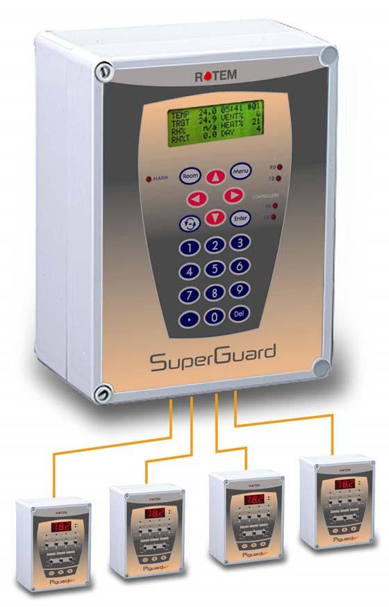
5 5 Distributor and Installer Information Please fill in the following information about your Product. Keep this manual in a clean, dry place for future reference. Distributor's Name Distributor's Address Distributor's Distributor's Phone Date of Purchase Installer's Name Installer's Address Installer's Installer's Phone Date of Installation System Specifications Introduction This manual provides easy to use information for installation, operation, long/short term planning and parts listing. The table of contents is an outline of the relevant information in this manual. Read this manual before operating your Rotem Controller. If you have any questions or comments regarding your controller please contact your local Rotem dealer. Components - SuperGuard - Piguard Plus - Mux 485 Communicator (optional) - Extension Box (optional)
6 6 General Description SuperGuard The ultimate in pig confinement controllers, provides you maximum capability with minimal complication in programming up to ten Piguard Plus room controllers. Equipped with an easy programming interface and 4x20 line LCD screen enables efficient access to the relevant information. The SuperGuard, also referred to by ROTEM designers as the Piguard Plus server, functions as a server to up to ten Piguard Pluses. It maintains extensive history logs for as much as 100 days. In addition, the user-friendly SuperGuard features a real time clock, a data plug for quick program transfer, plus multi lingual support. Piguard Plus ROTEM s latest breakthrough in environmental controllers, especially designed for the pig confinement industry. Piguard Plus satisfies the environmental requirements by optimizing control between input and output. Integrated into each controller are accurate inputs for temperature and humidity, seven output relays and four analog outputs for variable speed fans. Every Piguard can be programmed differently through the SuperGuard and sustain different accessories or ventilation options according to the farmer s needs. Each Piguard can operate independently, in case of SuperGuard malfunction or loss of power. Using an internal battery when the Piguard is operating alone, there is no history collection or possibility to change parameters.
7 Features SuperGuard 7 Easy programming LCD - 4x20 characters Positioning scrollbar Swift device and feature selection Data plug Large numeric keypad Built in EMI Filter. Communication with up to ten Piguard Plus units. Extensive memory of events & alarms Real time visual outlook Alarm system (for every Piguard Plus unit) Multi language Support. PC communication Piguard Plus Easy programming Programmable outputs Alarm system Large digital display Up to four temperature sensors 8 (+8) Output Relays 30 Amps Volt. 8 Relay Extension Box Connection Extensive Historical and Management Information Collection Integrated Static Pressure (Optional by Request) Alarm Relay 3 Digital inputs 2 Analog inputs (Potentiometer, other) V Analog Outputs Build in 4 Amp Variable Speed with Override 2 HP 30 Amp Relay Variable Speed Auto/Manual Override Switch. Plug in RS-485 Communication card with Lightning protection. Power Supply input build In EMI Filter and Lightning Protection Precision Control, Ventilation, Cooling, Heating, and Humidity treatment.
8 8 Getting Started 5 Step Installation Guide This is a quick 5 step guide that will help you figure out the order of actions for a proper system installation: 1. Hardware Installation: Read all technical specs' and use the wiring diagrams, from 38 on this manual, to properly install all hardware. 2. Piguard Plus Cold Start: Plug in the controller and hold its three keys simultaneously for a few seconds until a CLD sign will appear. 3. Piguard Plus Unit Number: press the two arrow keys together until the number sign (NO.) blinks. Select the unit number with the up and down arrows and press Select. 4. Super Guard cold start: Plug in the controller and hold the delete key (DEL) for a few seconds until a Cold Start sign will appear. 5. Super Guard setup (Room #0): Follow the instructions on page 16. Before making any changes make sure you are changing the correct room by checking the room number on the upper right side of the screen. 6. Super Guard Installation: Follow the instructions from page 34. If you have more then one room, don t forget to change room number and install the rest. 7. Super Guard Service: Calibrate your equipment on each room using the service menu. 8. Super Guard Control: Follow the instructions from page 19 regarding the control parameters for each room. 9. Super Guard Device: Follow the instructions from page 23 regarding the device settings for each room/ 10. Super Guard Management: Follow the instructions from page 27 regarding live stock and alarm management for each room. The History menu is for viewing purposes only.

9 9 SuperGuard Keyboard B C D A E F G Keyboard Functions A Menu Toggles the menu function B Room The room key is used to switch between rooms. Press the room key and press a number to reach the desired room. C Arrows Use the arrows to scroll a short press in any direction moves one notch. A long press will "fast forward" to the end. D Round Arrows The Round Arrows key is a used to scroll between options (Yes/No, On/Off etc). E Enter The enter key is a confirmation key. F G Numeric Pad Delete
10 SuperGuard Main-screen 10 TEMP 27.1 ROOM #01 TRGT 24.0 DAY 1 RH% 75.0 Hr. 13:21 RH%T 80.0 LEVEL 1 The main screen shows basic information regarding rooms controlled by the SuperGuard, depending on what equipment is plugged in. TEMP TRGT RH% RH%T 03:53 #01 DAY SPD1/2 % MIN VENT Current room temperature Target temperature Current room humidity Target humidity Clock time and room number Growth day Ventilation percentage (Variable speed fan). 1 for PG81, 2 for PG82. Ventilation mode (Fan/Natural/Tunnel) OUT Outside Temp.
11 11 In case of an alarm, a blinking message will appear on any one of the main screens in addition to the siren. Pressing "0" on the main screen, when the alarm message is on, will direct you to the source of the problem. Resetting the alarm is possible, but it only stops the siren and not the screen message. Only by fixing the problem will the message stop. Pressing the zero on the numeric pad, while the alarm is activated will open the room status screen. O.K No com. N/A Alarm A filled square indicates an alarm is on. A dotted square indicates that there is no communication with the Piguard Plus. Once communication is off there is no history accumulation in the SuperGuard. A dotted lined square indicates N/A (not available).
12 12 Hotkeys To reach the Hotkeys screens, press the Hotkey number while viewing the main screen. The room number is located on the upper right side of the Hot screen to view the status of deferent rooms, first enter the desired room using the room key and pressing the room number. Then press the desired screen Hotkey number. 1 - Main screen 2 - Temperature screen The temperature Hot screen shows important information regarding the temperature status. You can see the average temperature on the upper left side that shows the average of temperature sensors T1 through T4. On the right side, you can see the temperature for entering tunnel ventilation mode. T #01 T AVG T TUN T OUT 31.3 Room Number 3 Targets Screen This screen shows all of the target levels, selected for any of the controller's functions. TEMP 22.5 HHUNIDITY 85 TARGETS # Curtain Position screen This screen shows the curtain opening position in percent. If for example curtain 2 show 40%, it is 40% open. CURT.1 CURT.3 TUNNEL CURTAIN POSITION #01 50 CURT.2 40 CURT.4 INLET
13 Curtain Target This screen shows the target CURTAIN TARGET #01 CURT.1 50 CURT.2 CURT.3 40 CURT.4 TUNNEL INLET opening percent for each curtain. 6 - Curtain Steps This screen shows the number of steps for each curtain. CURT.1 CURT.3 TUNNEL CURTAIN STEPS #01 12 CURT.2 14 CURT.3 INLET 7 - System Status This screen shows if humidity treatment is ON/OFF, if the cycle is ON/OFF and how many seconds left for the current cycle. SYSTEM STATUS #01 HUMIDITY TREAT. ON/OFF CYCLE STATUS ON/OFF CYCLE LEFT Variable Status This screen shows the speed and Heat in percent for the variable devices connected to the controller. VARIABLE STATUS #01 HEAT 1 n/a heat 2 n/a FAN 1 30% FAN 2 40% FAN 3 n/a FAN 4 n/a
14 Relay Status shows active relays, pressing 9 again will open the extension box's relay activity RELAY STATUS #01 R1- R2- R3- R4- R5- R6- R7- R8- EXTENSION RELAYS '9' Relay Active Relay Not Active.. (Decimal point) - Weather Station screen This screen is available if you use ROTEM weather station. This screen displays outside conditions, like Temperature, Rain, Wind Speed, Humidity, Rain Flow and Wind Direction measured by the weather station. WEATHER STATION #01 TEMP 12.5 HUM. 59 RAIN NO R.FLW 4 W.SPD 3 W.DIR 172
15 15 SuperGuard Setup. For SuperGuard setup select room, then 0 and "Enter" from any of the main screens. The SuperGuard setup is a procedure for customizing the SuperGuard unit to match the system. SuperGuard ===COMM.=== SuperGuard# 0 Baudrate 4800 Total Rooms 1 =Language= Language English ===UNITS=== Temp. F Press IN.W.C Other Units IMPER =OUT TEMP.= From Room 0 ===TIME=== Time(hh:mm) 12:06 =PASSWORD= Full Access 0 Read Only 0 SUPERGUARD SuperGuard identity (Max-32). BAUDRATE TOTAL ROOMS Select communication baudrate. Set the number of Piguard Pluses connected to the Super Guard (Max-10). Make sure you define the Piguards' numbers in a following order without skipping digits. For example: 1,2,3,4... If not set this way, the SuperGuard will not detect any Piguard Pluses. After defining the number of Piguard Plus controllers, the SuperGuard begins a search to find the controllers defined.
16 16 LANGUAGE TEMPERATURE UNIT PRESSURE OTHER UNIT TIME Select language. Select between Celsius and Fahrenheit. Select between Milibar, IN.W.C, Pascal, CM.W.C, MM.W.C. Select between meter and imperial. Controls the speed and rain flow. Units for speed are meter/h or mile/h and for rain millimeter/h or inch/h. Set clock time. The last three parameters are general for all of the Piguard Pluses.
17 17 Y Setting tables Make sure you start any changes by checking the room number on the upper right side of the window. 1. Time: (hh:mm) Set a time period for the function you want. You can set up two different time periods for the same function. When more than one time periods correspond, the shortest time frame automatically activates. The chart below shows the active time period as the highest bracket on the Y axis. ACTIVE PERIOD # From To :00 09:00 16:00 10:00 22:00 14:00 21:00 20:30 This table is an example and do not appear at this form on the controller. 9:00 14:00 16:00 21:00 10:00 20: 30 8:00 22:00 X Set on/off time to 0 for no operation and 0 to off time for continues operation. 2. Floating Point: (format 0.00) the number of zeroes after the point will determine the resolution. 3. Function Switcher: To switch between options use the Round Arrows key. 4. Scrollbar: The scrollbar gives an indication on the user s location on the table.
18 18 1 CONTROL 1.1 Temp curve TEMP CURVE #01 # Day Target Low Alarm High Alarm The PIGUARD provides separate temperature curves for target and low/high alarms. Set growth day, target temperature and low/high alarm temperatures and the controller will create a curve for each one and use it as reference. The program will alter at midnight prior to the next day on the next row programmed. There are up to 10 programmable rows, but the controller will maintain yesterday s settings for every empty line, therefore it is not necessary to fill the entire table. Limits: Day Target 0-40c Alarm low 0-40c (without floating point) Alarm high 0-40c (without floating point) 1.2 Humidity HUMIDITY #01 # Day Target Inc. Cyc Inc. Spd Set the day and target for a given day. The controller will produce a curve. There are up to 10 programmable rows, but the controller will maintain yesterday s settings for every empty line, therefore it is not necessary to fill the entire table. There are two restrictions under system set-points (menu 67) regarding the humidity treatment: Max vent: high limit ventilation, beyond, treatment is stopped. Max heat: high limit heat, maximum heat allowed by treatment. Limits Day: Target: 0-100% Inc. Cyc (Increase Cycle Sec.): this parameter is in seconds and will represent the following: in case of a humidity treatment, the controller will increase the cycle on time on the account of the off time by this amount of seconds. Inc. Spd (Increase Speed Fan %): increase speed fan in the amount of percent set in case of a humidity treatment.
19 Min. Vent. Timer MIN. CYCLE FANS #01 #Day On(sec) Off(sec) This function operates without a curve and each day is an independent working day. The program will alter at midnight prior to the next day on the next row programmed. ON/OFF (sec.): Cycle by seconds. 1234: select the fan to operate during the cycle. In the example above, fan 1 will operate from day 1 to 10 and fans 1+2 will operate from day Min Vent Pos. MIN VENT POS. # Day V-Fan1 V-Fan2 V-Fan3 V-Fan4 INLET CURTAIN MIN CURTAIN MAX This table has a different operation for each mode: 1. Minimum Speed Fan and inlet opening percentage, at MINIMUM VENT mode. 2. Minimum and Maximum curtain opening percentage at NATURAL mode. The settings in both modes are per growth day with a curve between growth days. Variable speed fans in minimum ventilation: If the speed is Zero the fans will be OFF in minimum vent and will begin operation according to the parameter in the system parameters. Note: in case the parameters in this table is different then the one in the system parameter, the system will regard the higher one. If the speed is less than minimum motor speed in the system parameters then it will work according the minimum motor speed.
20 Static Pressure STATIC PRESSURE #01 OUT TEMP LOW 5 PRESS. (LOW T) 0.08 OUT TEMP HIGH 35 PRESS. (HIGH T) 0.12 TUNNEL PRESS LOW ALARM 0.05 HIGH ALARM 0.15 BAND 0.04 WIND DELAY (s) 10 PRE OPEN (s) 5 Pressure Out Temp low: Set outside low temperature definition. Press (Low T): Static pressure target for the outside low temperature ( See graph below, point 1). Out Temp High: set outside high temperature definition. Press (High T): Static pressure target for outside high temperature ( See graph below, point 2). Tunnel Pressure: Static pressure target during tunnel ventilation mode. Low Alarm: If static pressure drops below set point alarm will sound. High Alarm: If static pressure rises above set point alarm will sound. Band: Set band zone to balance the system. Wind Delay: Static pressure is affected by wind, this definition is to ensure that an alarm is given due to a stable change in pressure and not an accidental one, that may have been caused by a wind gust. High Alarm 1 Tunnel Pressure 2 Static Pressure Low Alarm Temp Pre Open: Time setting for curtains to open before fans activate. This is to make sure the curtains are open before fan activity.
21 1.6 Wind Program WIND PROGRAM Speed Opening Low High The values on this screen represent curtain opening percentage for high and low wind speeds. Below the low speed the opening will be 100%, between the low and high there is a curve for the curtain opening and above the high speed, the opening will be according to the high speed. 1.7 System Parameters TEMP SYSTEM PARAMETERS Offset: Use this parameter to change the offset target =====TEMP===== temperature up or down for any purpose. Offset Default: 0 ====TUNNEL==== TUNNEL From Day(0-No) From Day: From this growth day starts Tunnel Tunnel Curt. Pos Ventilation. 0- tunnel ventilation not active. Each Fan Open Default: 0 (Not active) ===HUMIDITY=== Tunnel Curtain Position: the minimum tunnel curtain Band opening position in % when entering tunnel mode. Treat by Heat Default: 50% Treat Delay (m) Each Fan open: Additional operating power percentage ==COOL CELL== for fans during tunnel ventilation mode. From Day(0-No) Default 10 Temp Band HUMIDITY Band: Once the humidity rises above the target, Humidity Band treatment starts operating until dropping below the ===FOGGERS=== target + band. That is to prevent from bouncing. From Day(0-No) Example: The target is 80% and the band is 2%. Temp Band The treatment will start when reaching 80% and stop Humidity Band only under 78%. ===SPEED FAN== Default: 5 Min Motor 1 Spd Treat by Heat: Select YES to use heaters at humidity Min Motor 2 Spd treatment. Min Motor 3 Spd Default: Yes. Min Motor 4 Spd Treat Delay: Humidity treatment delay time in minutes. Freeze Protect Default: 0 (No treatment) ===VAR. HEAT== COOL CELL Minimum Heat From Day: From this growth day cooling starts. 0- ==WIND SPEED== Cooling not active. Wind Gust (sec) Default: Day 21 Emergency Speed for Rain Temp Band: See cooling table page 20. Default: 0.5 Humidity Band: See cooling table page 20. Default: 2% FOGGER From Day: From this growth day cooling starts. 0- Cooling not active.

22 22 Default: Day 21 Temp Band: See cooling table page 20. Default: 0.5 Humidity Band: See cooling table page 20. Default: 2% SPEED FAN Minimum Speed: Safety speed fan operation delay. This is the Fan minimum speed to begin operation. Default: 30. Freeze Protect: A general protection for the variable speed fan motor. When the variable speed fan starts from zero speed, the freeze protection activates it to 100% for 5 seconds. Default: No VAR. HEAT Minimum Heat: minimum heaters operation for safety measures. This parameter refers to both var. heat 1 and var. heat 2. Default: 30% WIND SPEED Wind Gust: delay time for wind gust or direction change in seconds. Default: 60 seconds. Emergency: above this wind speed the system will close all the curtains. The units are meter/h or mile/h according to the selection in the setup screen (room #0) Default: 20.0 Speed for Rain: in rain time this will be the minimum wind speed for making any curtain position changes in order to prevent rain from entering the room. The units are meter/h or mile/h according to the selection in the setup screen (room #0) Default: DEVICE 2.1 Temp Setting TEMP. SETTING #01 FUNCTION ON OFF Tunnel Spd Fan * Curtain 1 Curtain 2 FAN 1 H. Lamp 1/2 SET TEMP Var. Heat-1 Heater (24.0) * -1.0 This example contains several options. All options are available during relay layout and are set according to the devices on your farm.
23 23 SET TEMP (Target): Changing the set temperature will change the offset in system parameters. The ON/OFF values are the offset above/below target to trigger cooling/heating. * The Off value for Variable speed Fans and Variable Heat sets the band range. The example below matches the Temp Setting table and as you can see, the band range for the Speed Fan is 3 and starts at 1 so the controller will create a band between 1 and 4. Above 4 the Speed Fan will operate constantly. The same applies for Variable Heat. Variable Heat 1 % Speed Fan According to table 1.4- Minimum Vent. Position for each speed fan. According to system parameter Minimum Heat. Band Band Will operate If Min Vent is marked +. Temp Temp. Target Target 2.2 Curtain CURTAIN ====GENERAL==== Decrease Delay 3.0 Increase Delay 5.0 Calibration Steps 99 ==CURTAIN NO. 1== No. Of Stages 5 Operation Mode AUTO First Stage (%) 0 ==CURTAIN NO. 2== No. Of Stages 5 Operation Mode AUTO First Stage (%) 0 =====TUNNEL===== No. Of Stages 5 Operation Mode AUTO First Stage (%) 0 Dip Switch Configuration: On the PiGuard Plus's CPU there are two parallel blue dip switches, located on the left hand side of the PCB. If you want hardware protection during curtains' activity, make sure you connect the curtains in pairs, according relay numbers (1,2; 3,4; 5,6; etc.) and to move the three matching dipswitches to off position. On the PCB is written which switch goes with the relay. Not doing so may result in the motors closing and opening the curtains simultaneously, due to bad configuration or programming on behalf of the user. GENERAL Increase/Decrease Delay: delay at least the length of time specified in this section before moving again.
24 24 Calibration Steps: After moving the number of times specified in stages for calibration, the curtains go to the nearest limit (fully open or fully closed) one at a time in order to calibrate their position counters. Whenever any curtain reaches one of the limits, its calibration counter automatically resets. CURTAIN NO. ½ No. Of stages: Divide the curtain stages for opening and closing and the controller will translate the number into percentage. (In the table above each stage is of 20%) Operating Mode: In Auto mode the controller will manage the opening/closing or you can manually open/close or stop the curtain all together. First Stage: This option allows programming an individual percentage for the first stage 2.3 Cool Cell The cooling table provides settings for the evaporative cool cell system. There Cool Cell #01 # From To Diff %RH On Off :00 10:00 20:00 18: are up to10 fragments allowing precise control over this system. Several fragments can be selected for the same day. FROM: (HH:MM) Start time. TO: (HH:MM) End time. DIFF: Differentiation from target temperature to activate cooling. When temperature raises diff above target, cooling process will begin. When temperature reduces back to target, cooling process will stop. %RH: As long as the humidity + Band are below this level the cooling operates. Cooling stops only at humidity level + band. (See figure below) ON/OFF: (sec) On/Off cycle by seconds. Band: The cooling table has its own happy zone for temperature and humidity that can be set at the system parameters under cooling section. The cooling system turns on the amount above specified in the column Diff and turns off when the temperature drops the amount specified in the band. Temp + Activate - (Diff) Stop Band Temp. RH% + - Stop Activate Band
25 Foggers The Foggers' table provides settings for the fogger system. There are up to10 COOLING #01 # From To Diff %RH On Off :00 10:00 20:00 18: fragments allowing precise control over this system. Several fragments can be selected for the same day. FROM: (HH:MM) Start time. TO: (HH:MM) End time. DIFF: Differentiation from target temperature to activate cooling. When temperature raises diff above target, cooling process will begin. When temperature reduces back to target, cooling process will stop. %RH: As long as the humidity + Band are below this level the cooling operates. Cooling stops only at humidity level + band. (See figure below) ON/OFF: (sec) On/Off cycle by seconds. 2.5 Light LIGHT # Day From To :00 10:00 12:00 16:00 Set the on/off times according to growth day, there are up to five programmable lines. 2.6 Feed LIGHT # Day From To :00 14:00 12:00 16:00 Set from what hour to what hour you want the feeding to take place, there are up to five programmable lines.
26 Extra system EXTRA SYSTEM #01 # From To F.Temp. T.Temp. on off :00 14:00 12:00 16: Any relay can be set as an extra system. The extra system s relays will activate according to the settings in this table and regardless of the conditions, or other devices. FROM: (HH:MM) Start time. TO: (HH:MM) End time. To/From Temperature(F.Temp/T.Temp): the temp range for extra system activity. ON/OFF: (sec) On/off cycle by seconds. This table has up to ten programs. 3 MANAGEMENT 3.1 Animal inventory ANIMAL INVENTORY #01 Add Mortality Animal Placed Animal Update This table provides an update for animal inventory. Add Mortality: insert mortality. Animals Placed: insert animals placed. Animal Update: update number of animals. In case the wrong figures are accidentally entered, it is possible to correct them by entering negative figures. 3.2 Day & Group DAY & GROUP #01 Growth Day New Group Group No. 2 Yes/no 4 Day and group keeps monitor the growth of groups Growth Day: Set the number of growth day. This parameter can also help determine the animals age. New Group: To start a new group, select YES under new group fragment and the controller will automatically increase group number by one and set growth day to 1. Warning: When starting a new group, history will be deleted!!!

27 27 Group No.: You can manually change the group number. 3.3 Alarm setting ALARM SETTING Alarm Delay 60 =SENSOR RANGE= High Range 10 Low Range 50 ====HIGHE TEMP==== Out Compensate 0.0 Emergency Temp 35 =====LOW TEMP===== Var Fan Stop NO ===WATER & FEED=== Max Water/hour 0 Max Feed/hour 0 ===Aux. Alarm=== Aux Relate f() NONE ALARM SETTING Alarm Delay (sec): represents the number of seconds between failure detection and the alarm operation. If the problem is solved before the delay time ends, an alarm will not be recorded in the history log. SENSOR RANGE Low/High: High and low temperature ranges beyond which alarm is activated. HIGH TEMP Out Compensation: This parameter is added to the high temperature alarm when outside temperatures are high, like noontime in desert countries. Ensuring you won't get an alarm just because it's a hot day. The emergency temperature has no compensation, so the compensation feature only works when temperatures do not exceed the emergency temperature. Example: Outdoor+comp. >Alarm then Alarm=Outdoor+Comp. For example: IF the pre set compensation is 2 F, the outside temperature is 75 F and alarm is set to 76 F, the controller adds the outside temperature to the comp, and the alarm will rise to 77. (75+2=77) Emerg. Alarm Out temp. Compensation. Comp. Target Emergency Temp.: The temperature beyond which the controller goes into emergency mode and an alarm is activated. LOW TEMP
28 28 Variable Speed Stop (Yes/No): When in low temperature alarm, decide whether to keep variable speed in minimum operation or totally shut down the function. WATER & FEED Max Water/Hour: A quantity of water per our, above which alarm will activate. Max Feed/Hour: A quantity of feed per our, above which alarm will activate. AUX. ALARM: When assigning a related function, alarm occurs if the associated digital input fails to follow the relay. Digital input must be active when its associated relay is on. If there is no related function the alarm will turn on when digital input is active. 3.4 Alarm Reset ALARM RESET #01 Alarm Reset NO 3.5 Password Full access -Password grants complete control. Read access - Password grants read access only. To reset the alarm press Enter and use the Round Arrows key to change from NO to YES. 4 HISTORY The history section maintains a memory of activity of the last 100 days and 100 events or alarms. 4.1 Temperature TEMPERATURE #01 DAY MIN AVG MAX Humidity HUMIDITY #01 DAY MIN AVG MAX Sensors: Data collection for minimum, maximum and average in temperature and humidity for the last 100 days.
29 4.3 Water WATER #01 DAY DAILY % N/A 5 29 DAY: Growth day. DAILY: Daily consumption. %CHANGE: % Change from previous day. 4.4 Feed FEED #01 DAY DAILY % N/A DAY: Growth day. DAILY: Daily consumption. %CHANGE: % Change from previous day. 4.5 Mortality MORTALITY #01 DAY DAILY 0 1 TOTAL N/A 1 DAY: Growth day. DAILY: Daily mortality. TOTAL: Mortality total since growth day one. 4.6 Heater HEATER ROOM #01 DAY Heat 1 1:05 00:42 Heat 2 00:15 00:02 The history heater will show the amount of HH:MM the heater was on that day.
30 4.7 Alarm 30 MESSAGE Press. Fail High Temp ALARM #01 TIME 18:50 10:45 DAY The following is an example of an Icon status that indicates activation of alarms. NOT ACTIVE AN ALARM THAT WAS RESET ACTIVE There are 21 different possible alarm messages: 1. Ana. In Fail - analog input failure 2. High Temp - high temperature alarm 3. Low Temp low temperature alarm 4. Hum.Sen Fail- humidity sensor failure 5. Lost Comm- lost communication 6. W. Overflow- water over flow 7. F. Overflow- feed over flow 8. Sn. 1 Fail Sensor #1 failure. 9. Sn. 2 Fail 10. Sn. 3 Fail 11. Sn.1 Def Err- sensor definition error 12. Sn.2Def Err 13. Sn.3 Def Err 14. Sn.1 Out Rng- sensor out of range 15. Sn.2 Out Rng 16. Sn.3 Out Rng 17. Sn. Not Def- sensor not defined 18. Aux Alarm- auxiliary alarm. 19. Press. Fail 20. Low S. Press. 21. High S. Press.
31 Event EVENTS ROOM #1 1 2 EVENT Menu #11 Power up DAY 2 4 TIME 18:53 14:42 Besides the menu # event message there are three kinds of events: 1. Power up- how many times the controller was turned on. 2. Reset- how many times the controller was reset. 3. Cold- how many cold starts were performed. The events table is similar to the alarms table but without icons. For example: In the table above menu #11 means that there was a change of settings in this menu. 5 SERVICE 5.1 Temp calibration TEMP. CALIB. #01 Temp-1(Factor) 0.0 Temp-2(Factor) 0.0 Temp-3(Factor) 0.0 Temp-4(Factor) n/a The temperature sensor is a very accurate sensor with a deviation of 0.1. If needed, calibrate the temperature sensor by using a very accurate reference instrument and enter the offset number for each sensor in the Temp factor line. Use the up and down arrow keys to select sensors. 5.2 Humidity calibration HUM. CALIB. #01 Humid.(factor) 0.0 If needed, calibrate the humidity sensor by using a very accurate reference instrument and enter the offset number in the Humidity factor line. 5.3 Pressure calibration PRESS. CALIB. #01 Value A/D Press ENTER to calib
32 Analog Output Select the minimum Volt percentage for each output. (The default is 30%) ANALOG OUTPUT #01 # 0% 100% Output1 0.0V 0.0V Output2 0.0V 0.0V Output3 0.0V 0.0V Output4 0.0V 0.0V The minimum Voltage is used to protect your electric equipment. If the min. is 30% and 10% operation was set for the Output; the controller will run on 37%. 5.5 Water & Feed Water/feed #01 Water per pulse 0.1 Feed per pulse 1.0 The water and feed system operates on a pulse counting method. Enter the amount of feed/water per pulse. 5.6 Version Observe the Piguard software version. 5.7 Read Plug NO Read Plug? YES Use the arrow keys to shift from NO to YES and press Enter to read from data plug. 5.8 Write Plug NO Write Plug? YES Use the arrow keys to shift from NO to YES and press Enter to write over the data plug.

33 33 6 INSTALLATION 6.1 Relay layout # FUNCTION MNT None --- None --- Each relay can be defined to any of the functions on the following list: None Heater 1-2 Heat lamp 1-2 Fan 1-8 Cool Cell Curt. 1 open Curt. 1 close Curt.2 open Curt 2 close Tunnel open Tunnel close Inlet open Var. inlet Open Var. inlet Close Inlet close Extra system Alarm MNT: Minimum Vent / Natural / Tunnel Use the Round Arrows key to run through the list of functions and press enter to select a function. As long as the function is marked with a minus sign, it will not operate even if the conditions are suitable. 6.2 Sensors ANALOG INPUT #01 Temp-1 Temp-2 Temp-3 Temp-4 Humidity IN NONE OUT YES YES OPTIONS IN / NONE IN / NONE IN / NONE NO / YES/OUT NO / YES
34 34 The Analog inputs accommodate up to- three temperature sensors and one humidity sensor. Two can be defined for use inside the house and up to one can be used out of the house. Just mark "in" for a temperature sensor connected in the house and out for a temps. Sensor outside of the house. 6.3 Digital input DIGITAL INPUT #01 OPTIONS Input-1 Water None / Water / Feed / Aux. Alarm Input-2 Feed Input-3 None There are 3 digital inputs and a selection between water, feed, aux. alarm or none. AUX. ALARM: Once operating function, a digital input is sent to make sure that it is actually on, and if not the alarm starts. 6.4 Analog output ANALOG OUTPUT #01 # FUNCTION MNT 1 Var. Heat Var. Heat Var. Fan Var. Fan Use the Round Arrows key to run through the list of outputs and press enter to select an output. MNT: Minimum Vent / Natural / Tunnel 6.5 Variable Speed Fan VAR. SPEED FAN #01 ACTIVE MNT 1 VAR. Fan 1 YES Var. Fan 2 YES ---
35 6.6 Sensor Definition 35 FUNCTION 1234 Average +-+- Tunnel +--- Heater Heater Heat Lamp Heat Lamp Fan Curtain Cool cell ---- Ex. System ---- Tun. Curt ---+ Speed fan ---- Var. Heat --+- Select the temperature sensors 1-4 to use for each function using the Round Arrows key to apply and remove check marks. Average- the average definition refers to the average temperature, according to the sensor defined. If two minus symbols are defined for a certain sensor, that sensor will operate according to the average temperature definition. 6.7 Curtain Setup CURTAIN SETUP #01 CURTAIN OPEN CLS Curtain Curtain Curtain Curtain Tunnel Inlet Curtain Setup tells the controller how fast your curtains and side inlets move. It needs this information to properly calculate automatic inlet advance as well as inlet and curtain positions.
36 36 Piguard Pluses Cold Start In order to execute a cold start, disconnect the power, then reconnect the power while pressing the 3 buttons of the Piguard Plus together and hold them for about 2 seconds. The following will appear: C L d When this screen appears the controller preformed a cold start. Cold start will erase all data and history from the memory and load factory defaults!!! Set Unit Number Press the two arrow key simultaneously until NO. is blinking. Set the unit number with the up and down arrows and press Select. Main Menu Once the Piguard Plus is activated the main screen will appear showing the inside average temperature of the rooms. Pressing SELECT allows the user through the main screen s information. trg: The target temperature for the room. (Can be changed from the Piguard Plus itself only if a curve was not defined.) rh: Humidity in room. rh.t: Target humidity. day: Growth day for the room. The display alternates between the name and the figure. Calibration Temperature sensors are very accurate and most likely will not require calibration. However, if calibration is required it will be done in the following way: Temperature sensor calibration Use an accurate thermometer reference. Place it near the temperature sensor. Make sure that the inside temperature is stable. Calibrate the temperature sensor immediately after reading. Calibration procedure 1. In order to get to the calibration menu press select and the up arrow keys simultaneously and hold them together for about two seconds. 2. The display alternates between the sensor number and the temperature measured. 3. Use the arrow key to change the temperature. 4. Press select to move through the sensors and the arrows to change temperatures NOTE: Calibration of humidity sensor is done exactly the same way; the only difference is that instead of measuring temperature, the humidity is measured by an external humidity sensor.
37 37 Test The test option is used mostly in the installation process and it enables the installer to check systems. In order to get to test menu, press select and down arrow keys simultaneously and hold them together for about two seconds. The display alternates between the name of the I/O and an ON/OFF sign. Pressing the arrow keys allows switching between on and off. rl.1-7: Relays 1 to 7. SPd: Variable speed. (Check minimum to full capacity using the arrow keys) AO1-4: Analog outputs 1 to 4. t1, t2: Temperature sensors with the A/D counts blinking on the screen. Hu: humidity sensor A/D counts. Ai1-2: Analog inputs 1 to 2. Prs: Pressure A/D counts. DG1-3: Digital inputs 1 to 3.
 5 analog outputs 20MA 0-:-10V 1 humidity sensor inputs 0-:-3V 2 analog inputs 0-:-5V Digital inputs 3 digital inputs dry contact")
38 38 Technical Specifications Power supply Mains voltage single phase 115/230VAC Main fuse 315 ma Secondary fuse 1 A Maximum power consumption 10VA Available power for peripheral equipment Analog Inputs 2 analog inputs for temperature sensors RTS-2 (THERMISTOR) 5 analog outputs 20MA 0-:-10V 1 humidity sensor inputs 0-:-3V 2 analog inputs 0-:-5V Digital inputs 3 digital inputs dry contact 5V/2mAmp Relays outputs 7 N.O. power relay 2HP 30Amps 250Vac Housing Dimensions (LxWxH) 92.5x73x36 Ambient climate Operating temperature range 32º F to + 122º Storage temperature range 14º to + 158º Indoor Applications The equipment is designed for use in Indoor Applications only! Environmental Protection Recycle raw materials instead of disposing as waste. The controller, accessories and packaging should be sorted for environmentalfriendly recycling. The plastic components are labeled for categorized recycling.
39 39 Piguard Plus Installation Guide. Sensors and Shielded Wiring 1. For long shielded wires, connect the shield to ground at one end only. 2. From the ground terminal, run a heavy wire directly to the ground rod. It is acceptable, if necessary, to run the heavy ground wire to the electrical service grounding system rather than directly to the ground rod. 3. Do not use light wires for these ground connections. They must carry heavy lightning currents, sometimes exceeding thousands of amperes. Certainly, do not use the shielding of sensor and low voltage wiring for this purpose. 4. Ensure that all ground connections go to a single local point. When lightning strikes, grounds a meter or two apart will be at significantly different voltages. If you have several electronic boxes with individual grounds, connect all these together to a single point (If Possible), preferably to the surge protector ground. This should continue to the ground rod or the electrical service. In particular, avoid grounding any controls remotely through shield wiring. 5. Do not use shields to create a path for lightning. For long shield wires, such as building to building runs, connect the shield to ground at one end only, to reduce the chance of conducting lightning from one building to another. 6. When splicing sensors to longer wires, ensure that the splice is waterproof. Use adhesive lined heat shrink (marine grade) to make waterproof connections. 7. Use a good compression connector for splicing. This is better than soldering. Do not simply twist wires together and then cover with electrical tape. 8. Keep sensor wiring separate from other power distribution and high voltage wiring. Ensure that lightning on other wiring will not transfer to the sensors. 9. Install outside temperature sensors so that the sun will not cause false readings, and so that exhaust air from the building will not affect the sensor. Installation and Electrical Connections 1. Install computerized electronic controls at least one meter (three feet) away from interference sources such as high voltage wiring to motors, variable speed, light dimmers, relays. 2. Install electronic controls in a separate ventilated control room that is protected from extreme temperatures and dirty environments. Place the controls so that the operators can conveniently use the control and read indicators and displays. 3. Give your installation a professional appearance, with all wiring in conduit or neatly installed. Keep low voltage wires separate from high voltage wires. 4. Use shielded wiring for low level signals. For buried wiring (building to building runs) use high grade jell filled cables that are impervious to moisture. 5. Seal cable entry points and control boxes to prevent contamination and corrosion. If you use silicon sealant with acetic acid cure, keep the control open and ventilated until cured. Otherwise, the acetic acid will attack the metal parts, including circuitry. 6. Drill cable entry holes on the bottom of the box only.
40 Mechanical Installation Guide 40 The Piguard PLUS must be installed by an authorized electrician. Power must be disconnected to avoid electrical shock and damage. To avoid exposing the Piguard Plus to harmful gases or high humidity, it is recommended to install it in the service room. Installation Category (Over voltage Category) II The power supply to the controller should be protected by 10 Amps circuit breaker All electrical connections should comply with National Electrical code (NEC) 1. Screw the metal sheet on the back of the box using the 4 supplied screws. Mount the Piguard Plus through the mounting holes. (see next page) 2. Open the enclosure lid by unfastening the four screws. 3. Drill holes at bottom of the box and place cable holders. 4. Place the required cables through the cable holders at the bottom of the unit. Connect the wires according to the wiring diagrams. 5. Make sure that you use wires large enough for the load of the variable speed. 6. To connect temperature and humidity sensors use shielded two or four conductor #18-#24 gauge cables. Connect the shields to the Ground metal strip. Do not connect the shields to more than one point, or you may induce ground loop currents. 7. Close the Piguard Plus enclosure lid carefully and tightly. Use RTV silicon or equivalent sealant to seal the cable holders. 8. After installation is completed, operate the Piguard Plus for a few hours and re- check for proper operation.


41 41 Metal Sheet Assembly Diagram Hanging Holes Hanging Holes Instructions 1. Screw the metal sheet on the back of the controller (Clear side facing controller) using the supplied four screws. 2. Measure the outer hanging holes of the sheet and drill hanging screws parallel to the holes. 3. Hang the controller.

42 42 SuperGuard/Piguard Plus Network Connection Modem To P.C com Dip Switch Configuration: Mux 485 On the PiGuard Plus's CPU there are two parallel blue dip switches, located on the left hand side of the PCB. If you want hardware protection during curtains' activity, make sure you connect the curtains in pairs, according relay numbers (1,2; 3,4; 5,6; etc.) and to move the three matching dipswitches to off position. On the PCB is written which switch goes with the relay. Not doing so may result in the motors closing and opening the curtains simultaneously, due to bad configuration or programming on behalf of the user. SuperGuard Piguard Plus Piguard Plus Piguard Plus
43 43 Piguard Plus Wiring Diagram (Analog Output, Power, Variable speed, RHS-2) Variable speed 1 & 2 N ~ Power Digital Input Humidity Analog output Number Wire 25 COM 26 Dig 1 27 Dig 3 28 Dig 2 12 White 14 Red 16 Black 3 COM COM COM COM v Analog Output 0-10v Analog Output D.Input 3 D.Input 2 D.Input 1 COM Up to 4 Analog Outputs Digital Input

44 Piguard Plus Wiring Diagram (Relays, Potentiometer, RTS-2) 44 Temperature sensor Analog input Number Wire 18 COM 20 T1 21 T2 22 T3 23 T4 11 A. in 2 12 A. in 1 13 A. in 3 15 A. in 4 17 Vpot 19 COM Ain 1 COM Line 1 POT COM T1 T3 RTS-2 Heater Line 2


45 45 Communication Wiring Diagram To P.C com. Modem Mux-485 SuperGuard com, rx, tx com, rx, tx A to A, B to B (shield to GRD at one end only) Room 3 Room 2 Next Room Previous Room Room 1 Shield connected Shield is connected to GND only on one end to each piece of cable Shield connected


46 46 Piguard Plus Wiring Diagram Extension Box Extension Box When connecting the relevant connections (see above) the connections of both the Piguard Plus and the Extension box unit must be with no power. Before turning the Piguard Plus on, make sure the Extension box is plugged in first, so that the Piguard Plus identifies the Extension box.
Element. Controller. Manual for use and maintenance. Element. Climate Controller. Ag/MIS/UMGB /17 Rev 1.0 P/N:
 Manual for use and maintenance Element Controller Element Climate Controller Ag/MIS/UMGB-2439-02/17 Rev 1.0 P/N: 110584 Element Manual for use and maintenance Original instructions This manual for use
Farm Hand CCU 111 / CCU 10R. Manual for use and maintenance. Farm Hand. Climate Controller. HC/MMA/UmGB /13 rev 1.
 Manual for use and maintenance Farm Hand CCU 111 / CCU 10R Farm Hand Climate Controller HC/MMA/UmGB-2043-01/13 rev 1.8 P/N: 110131 Farm Hand CCU 111, Farm Hand CCU 10R Manual for use and maintenance Revision:
REC-8R Environmental Control. Operation and Installation Manual
 REC-8R Environmental Control Operation and Installation Manual This manual is published by Rotem Computerized Controllers Ltd. All rights to this publication are reserved. No part of this document may
Poultry House Control
 User s Manual Poultry House Control This manual is published by Rotem Computerized Controllers Ltd. All rights to this publication are reserved. No part of this document may be reproduced, transmitted,
Rotem One Touch. User Manual PRELIMINARY DOCUMENT. Ag/MIS/UmGB /18 Rev 1.0 P/N:
 User Manual Rotem One Touch Rotem One Touch Ag/MIS/UmGB-2603-06/18 Rev 1.0 P/N: 110741 Rotem One Touch User Manual Revision: N.1.0 of 02.2018 Product Software: 7.14 This manual for use and maintenance
Platinum Touch/Rotem One Touch
 User Manual Platinum Touch / Rotem One Touch Platinum Touch/Rotem One Touch Climate Controllers Ag/MIS/UmGB-2583-05/18 Rev 1.0 P/N: 116556 Platinum Touch/Rotem One Touch User Manual Revision: N.1.0 of
No part of this publication may be reproduced, stored in an automated data file or made public in any form or by any means, whether electronic,
 No part of this publication may be reproduced, stored in an automated data file or made public in any form or by any means, whether electronic, mechanical, by photocopying, recording or in any other manner
EXPERT TRI-STAR. Temperature controller. User s Manual
 Temperature controller r s Manual WARNINGS The warranty can be void if this product is used in a manner not specified by the manufacturer. Every effort has been made to ensure that this manual is complete,
Dryer Controller M720
 User Manual Dryer Controller M720 Hardware version 2.00 Software version 2.00 Manual M720 Dryer controller Page 1 of 60 Document history Preliminary version: - Created in April, 2009 Hardware Version 2.00,
User Manual. Dryer Controller M720
 User Manual Dryer Controller M720 Hardware version 1.00 Software version 1.00 Preliminary version Manual M720 Dryer controller Page 1 of 42 Document history Preliminary version: - Created in April, 2009
VAV Thermostat Controller Specification and Installation Instructions. Model TRO24T4XYZ1
 Model TRO24T4XYZ1 Description The TRO24T4XYZ1 is a combination controller and thermostat. The VAV Thermostat Controller is designed for simple and accurate control of any variable air volume box in a number
Rooftop Thermostat Controller Specification and Installation Instructions. Model TRT2422
 ºF / º C Rooftop Thermostat Controller Model TRT2422 Description The TRT2422 is a combination controller and thermostat with a built-in scheduler, which is designed for simple and accurate control of single
User manual and installation guide
 User manual and installation guide 31046005 Copyright Phason Inc. All rights reserved. Printed in Canada About the manual The manual describes the features of your control and how to use them; it does
Product Manual SZ1145
 Product Manual SZ114 General Purpose Monitor Communicating Controls Description The SZ114 is a microprocessor-based monitoring and alarm interface designed to monitor up to four 1000 Ω platinum temperature
Secondary Sensing System
 Secondary Sensing System Owners Manual Hired Hand Mfg., Inc. 1733 Co Rd 68 PO Box 99 Bremen, Alabama 35033 Manual No. 4801-2997 Rev 7-04 Owners Manual Secondary Sensing System Table of Contents Section
Temperature Controller CC24-7 UNIBOX USER S MANUAL Legion Dr. Mason, MI USA October 2010 Ph. (517) Fax (517)
 Fax (517)") 3 4 Temperature Controller USER S MANUAL Aerotech, Inc. FORM: QM1386 4215 Legion Dr. Mason, MI 48854-1036 USA October 2010 Ph. (517) 676-7070 Fax (517) 676-7078 FOR CUSTOMER USE Enter the serial number
3 4 Temperature Controller USER S MANUAL Aerotech, Inc. FORM: QM1386 4215 Legion Dr. Mason, MI 48854-1036 USA October 2010 Ph. (517) 676-7070 Fax (517) 676-7078 FOR CUSTOMER USE Enter the serial number
RC-112 Two Speed Heat Pump 3 Stage Heat / 2 Stage Cool With Energy Efficient Control
 O M N I S T A T ELECTRONIC COMMUNICATING THERMOSTAT Installation Manual RC-112 Two Speed Heat Pump 3 Stage Heat / 2 Stage Cool With Energy Efficient Control Document Number 13I00-5 November, 1997 CONTENTS
Product Manual SZ1144
 Product Manual SZ1144 Refrigeration Temperature Monitor Communicating Controls Description The SZ1144 is a microprocessor-based monitoring and alarm interface designed to monitor up to four 1000 Ω platinum
ECC-1 user manual and installation guide
 ECC-1 user manual and installation guide Table of contents Introducing the ECC-1...1 Features...2 Electrical ratings...2 Optional accessories...3 About this manual...3 Using the buttons...4 About the status
Application Manual Loop Water Controller
 Application Manual Loop Water Controller AM - LWC TABLE OF CONTENTS LIST OF FIGURES ii iii 1.0 SAFETY CONSIDERATION 1 1.1 Installation Recommendations 1 2.0 GENERAL DESCRIPTION 2 2.1 General Introduction
RC-101 Heat Pump Real Time Pricing System 2 Stage Heat / 1 Stage Cool
 O M N I S T A T ELECTRONIC COMMUNICATING THERMOSTAT Installation Manual RC-101 Heat Pump Real Time Pricing System 2 Stage Heat / 1 Stage Cool Document Number 13I00-4 January, 1997 Copyright 1997 Home Automation,
Carbon Monoxide Transmitter
 Introduction The CO Transmitter uses an electrochemical sensor to monitor the carbon monoxide level and outputs a field-selectable 4-20 ma or voltage signal. The voltage signal may also be set to 0-5 or
Rev Pulse Modulating Anti- Sweat Control (PMAC II) Installation and Operation Manual
 Installation and Operation Manual") 026-1501 Rev 5 3-20-03 Pulse Modulating Anti- Sweat Control (PMAC II) Installation and Operation Manual 1640 Airport Road, Suite 104 Kennesaw, GA 31044 Phone: (770) 425-2724 Fax: (770) 425-9319 ALL RIGHTS
026-1501 Rev 5 3-20-03 Pulse Modulating Anti- Sweat Control (PMAC II) Installation and Operation Manual 1640 Airport Road, Suite 104 Kennesaw, GA 31044 Phone: (770) 425-2724 Fax: (770) 425-9319 ALL RIGHTS
ELECTRONIC COMMUNICATING THERMOSTAT
 O M N I S T A T ELECTRONIC COMMUNICATING THERMOSTAT Installation Manual RC-81 Single Stage Heat/Cool Real Time Pricing System Document Number 13I00-2 January, 1997 Copyright 1997 Home Automation, Inc.
Evolution Environmental Controller. Hired Hand Manufacturing, Inc County Road 68 PO Box 110 Bremen, Alabama 35033
 Evolution 4000 Environmental Controller Hired Hand Manufacturing, Inc. 1759 County Road 68 PO Box 110 Bremen, Alabama 35033 Part No. 4801-5338 Rev 01-10 Owners Manual Evolution 4000 Table of Contents Section
Analog Room Pressure Monitor RPC Series
 Description The Room Pressure Monitor is used to measure differential pressure in the range of 0.125 to 1"wc or 30 to 250 Pa. It combines precision high sensitivity silicon sensing capabilities and the
CLEANROOM MONITOR CR3A Network - Installation Instructions
 CLEANROOM MONITOR CR3A Network - Installation Instructions INTRODUCTION The CR3 Series Cleanroom Monitor, was developed specifically to allow for monitoring of confined spaces with accuracy and reliability.
User manual and installation guide
 User manual and installation guide Copyright Phason Inc. Printed in Canada All rights reserved. 31045004 About the manual The manual describes the features of your PEC and how to use them; it does not
INSTALLATION & USER MANUAL
 INSTALLATION & USER MANUAL HC Digital Automatic Humidistat (Y3760) CONTROLS 506808-01 3/2016 Supersedes 6/2011 picture goes here THIS MANUAL MUST BE LEFT WITH THE HOMEOWNER FOR FUTURE REFERENCE NOTICE
ExactLogic BACnet Communicating Thermostat EXL01627 Sequence Datasheet Fan Coil with Modulating Fan and Heat or Cool Floating Heating and Cooling
 ExactLogic BACnet Communicating Thermostat EXL01627 Sequence Datasheet Fan Coil with Modulating Fan and Heat or Cool Floating Heating and Cooling DataSheet ev 1.12.304/4.0 June 14, 2016 Operating Sequence
ExactLogic BACnet Communicating Thermostat EXL01625 Sequence Datasheet Fan Coil with Modulatating H/C and PO-PC H/C
 ExactLogic BACnet Communicating Thermostat EXL01625 Sequence Datasheet Fan Coil with Modulatating H/C and PO-PC H/C DataSheet ev 1.10.403/4.02 November 6, 2012 Operating Sequence Standard Occupied During
DC200 Digital Dispenser Operating Manual
 DC200 Digital Dispenser Operating Manual 2015 Fisnar Phone: (973) 646-5044 E-mail: info@fisnar.com Table of Contents Product Safety Statements 4 Specifications 6 Accessories 6 External Controls 7 Machine
User Manual. Digi-Sense TC9500 Advanced Multiparameter Temperature Controller with Thermocouple, Thermistor, and RTD Inputs
 User Manual Digi-Sense TC9500 Advanced Multiparameter Temperature Controller with Thermocouple, Thermistor, and RTD Inputs Models 89800-03 and 89800-04 THE STANDARD IN PRECISION MEASUREMENT Table of Contents
Refrigeration Controller Operator s Manual (HRC) PO Box 6183 Kennewick, WA
 PO Box 6183 Kennewick, WA") Refrigeration Controller Operator s Manual (HRC) PO Box 6183 Kennewick, WA 99336 www.jmcvr.com 1-509-586-9893 Table of Contents TABLE OF FIGURES...1 OVERVIEW OF THE HRC CAPABILITIES...2 INSTALLATION AND
Refrigeration Controller Operator s Manual (HRC) PO Box 6183 Kennewick, WA 99336 www.jmcvr.com 1-509-586-9893 Table of Contents TABLE OF FIGURES...1 OVERVIEW OF THE HRC CAPABILITIES...2 INSTALLATION AND
Evolution 3000 and 3001
 Evolution 3000 and 3001 Environmental Controller Hired Hand Manufacturing, Inc. 1733 County Road 68 PO Box 99 Bremen, Alabama 35033 Controller Software Version V0.37 Part No. 4801-5307 Rev 2-11 Owners
MYRIAD TRIPLEX PUMP CONTROLLER INSTRUCTION MANUAL
 MYRIAD TRIPLEX PUMP CONTROLLER INSTRUCTION MANUAL MYRIAD TPC VISIT OUR WEBSITE SIGMACONTROLS.COM MYRIADI&O062705 2 TABLE OF CONTENTS INTRODUCTION 3 Ordering Information Specifications Features WIRING 7,8
Instruction Guide: Thermostat Operation
 Instruction Guide: Elite Communicating Thermostats TPCM32U03*/TPCM32U04* (*GSR, GSM, TRN, AST) INSTRUCTION GUIDE: ELITE COMMUNICATING THERMOSTAT Thermostat Operation NOTE: These communicating thermostats
Installation, Start-Up, and Operating Instructions
 Installation, Start-Up, and Operating Instructions CONTENTS Page SAFETY CONSIDERATIONS...1 GENERAL...1 INSTALLATION...1-5 Install Batteries...1 Select Transmitter Location (Optional)...1 Mount Transmitter
INSTALLATION MANUAL AND OPERATING INSTRUCTIONS
 AMB4/AMB8 MULTIPLE BOILER SEQUENCERS INSTALLATION MANUAL AND OPERATING INSTRUCTIONS ARGO (Technical Support) 2201 Dwyer Avenue Utica, NY 13501 (Corporate Sales) 85 Middle Road An ISO 9001-2000 Certified
Table of Contents 1. OVERVIEW SYSTEM LAYOUT SPECIFICATIONS FUNCTION... 11
 Table of Contents 1. OVERVIEW... 3 2. SYSTEM LAYOUT... 4 3. SPECIFICATIONS... 8 3.1 SYSTEM COMPONENTS...9 3.2 PLC INPUTS AND OUTPUTS...9 3.3 FUNCTION KEYS...10 3.4 DEFAULT SET POINTS AND TIMERS...10 4.
RC-90 / RC-90B Single Stage Heat/Cool Thermostat for Zone Control Systems Installation Instructions
 RC-90 / RC-90B Single Stage Heat/Cool Thermostat for Zone Control Systems Installation Instructions DESCRIPTION The RC-90 is a precision digital thermostat designed for 24 VAC single stage heating and
Installation, Start-Up, and Operating Instructions
 Installation, Start-Up, and Operating Instructions IMPORTANT: Read entire instructions before starting the installation. SAFETY CONSIDERATIONS Read and follow manufacturer instructions carefully. Follow
HP727S. Single speed swimming pool heat pump controller Operation manual TABLE OF CONTENTS
 HP727S Single speed swimming pool heat pump controller Operation manual TABLE OF CONTENTS 1. General Description 2. Specifications 3. Installation Instructions 4. Electrical Wiring 5. Instrument Wiring
Subcooling is defined as the point at which liquid is cooled below it s condensing temperature. Example: Refrigerant R404A
 Installation & Service Manual S E C T I O N 26 Enviroguard III ENVIROGUARD III is a patented refrigerant control system that utilizes floating head technology (Nature s Cooling). The amount of liquid refrigerant
OWNER S MANUAL Venstar Inc. 08/07
 Digital Thermostat residential THERMOSTAT T1 800 7-DAY PROGRAMMABLE up to 3-heat & 2-cool HEAT COOL HEAT PUMP Control up to 3 Heat & 2 Cool Stages 3 Configurable Outputs Adjustable 2nd & 3rd Stage Timers
Replaceable LED modules. Sleep or unattended mode. Auto-silence and auto-acknowledge
 Replaceable LED modules 11 Alarm Sequences as per ISA-18.1 standard Each channel/window fully field programmable RS232 or RS485 MODBUS-RTU communication Repeat relay for each window and multifunction relays
Halton SAFE / 7.14 user guide and installation instructions
 Halton SAFE / 7.14 user guide and installation instructions VERIFIED SOLUTIONS BY H A LTO N Enabling Wellbeing Table of contents 1 System description 3 2 User Accounts 4 3 Main menu 7 3.1 Main menu - Change
TECHNICAL MANUAL CVM 3000 C 5030 CV/04-99 GB
 Summary 1 CONNECTIONS... 8 1.1 TEMPERATURE PROBES...8 1.2 PRESSURE PROBES...9 1.3 LOW VOLTAGE DIGITAL INPUTS...10 1.4 LIVE DIGITAL INPUTS...11 1.5 RELAY OUTPUTS...12 2 VOLTAGE/FREQUENCY INPUT...13 3 POWER
B-40/B-41 Modulating Temperature Controller
 INSTALLATION & OPERATING INSTRUCTIONS B-40/B-41 Modulating Temperature Controller For Raytherm Boilers & Water Heaters H2 514-4001 WH2 2100-4001 Catalog No. 5000.70 Effective: 12-21-11 Replaces: NEW P/N
ACME ACME ENGINEERING & MANUFACTURING PB100 SPC-D INLET CONTROLLER. ACME ENGINEERING & MANUFACTURING CORP. PO BOX 978 Muskogee, OK 74402
 ACME ACME ENGINEEING & MANUFACTUING PB00 SPC-D INLET CONTOLLE ACME ENGINEEING & MANUFACTUING COP. PO BOX 978 Muskogee, OK 74402 Owners Manual PB00 SPC-D Table of Contents. atings and specifications...
Installation Instructions
 TP --- PRH --- A, TP --- NRH --- A PerformancetSeries Edger Thermidistatt Control Installation Instructions Programmable Control A07049 A07048 Non---Programmable Control NOTE: Read the entire instruction
Dryer Master Inc. Dryer Master AM 3. Product Manual
 Dryer Master Inc. Dryer Master AM 3 Revision 1.0 July, 2008 Revision 1.2 February, 2009 Revision 1.3 March, 2009 Revision 1.4 September, 2013 Prepared by: Dryer Master Inc. Dryer Master Inc 2008, 2009,
Public Safety DAS Annunciator Panel
 Public Safety DAS Annunciator Panel 120 VAC Models: 1221-A, 1221-B, 1221-C Revision D 91117 48 VDC Models: 1221-A-48, 1221-B-48, 1221-C-48 24 VDC Models: 1221A-24, 1221-B-24, 1221-C-24 CAUTION: (Read This
ECC-1 user manual and installation guide
 ECC-1 user manual and installation guide Table of contents Introducing the ECC-1...1 Features...2 Optional accessories...2 About the manual...3 Using the buttons...3 About the status LEDs...4 Using
Summit 3208GLD USER MANUAL. Electronics Line
 Summit 3208GLD USER MANUAL Electronics Line Table of Contents 1: Introduction... 2 2: Overview... 3 3: Keypad Functions... 4 3.1: Keypads... 4 3.2: 3108 LCD Keypad Layout... 4 4: Basic System Operation...
Chore-Tronics Load Cell Indicator
 Chore-Tronics Load Cell Indicator June 2008 CTB Inc. Warranty Load Cell Indicator CTB Inc. Warranty CTB Inc. warrants each new product manufactured by it to be free from defects in material or workmanship
CELLTROL II BIOREACTOR CONTROL SYSTEM OPERATIONS MANUAL
 Operation Manual Celltrol II Bioreactor Control System Page 1 of 33 Table of Contents 1) Introduction... 3 1.1) Scope of Document... 3 1.2) Control System Overview... 3 1.3) Introduction to Celltrol II...
Rev Pulse Modulating and Anti- Sweat Control (PMAC II Solo) Installation and Operation Manual
 Installation and Operation Manual") 026-1503 Rev 0 3-20-03 Pulse Modulating and Anti- Sweat Control (PMAC II Solo) Installation and Operation Manual 1640 Airport Road, Suite 104 Kennesaw, GA 31044 Phone: (770) 425-2724 Fax: (770) 425-9319
026-1503 Rev 0 3-20-03 Pulse Modulating and Anti- Sweat Control (PMAC II Solo) Installation and Operation Manual 1640 Airport Road, Suite 104 Kennesaw, GA 31044 Phone: (770) 425-2724 Fax: (770) 425-9319
TMC. Installation and Operation Manual TMC. Temperature and Pressure Monitoring for Heating and Cooling Applications. Temperature Monitoring Control
 Installation and Operation Manual Temperature and Pressure Monitoring for Heating and Cooling Applications Temperature Monitoring Control VALVE OPEN ALARM System= 128 o F Alarm At= 130 o F RESET /BACK
ARGO (Technical Support) 2201 Dwyer Avenue Utica, NY (Corporate Sales) 85 Middle Road
 2201 Dwyer Avenue Utica, NY (Corporate Sales) 85 Middle Road") ARGO (Technical Support) 2201 Dwyer Avenue Utica, NY 13501 (Corporate Sales) 85 Middle Road An ISO 9001-2000 Certified Company Dunkirk, NY 14048 www.argoindustries.com P/N 240005498A, Rev. 1.5 [02/07]
ARGO (Technical Support) 2201 Dwyer Avenue Utica, NY 13501 (Corporate Sales) 85 Middle Road An ISO 9001-2000 Certified Company Dunkirk, NY 14048 www.argoindustries.com P/N 240005498A, Rev. 1.5 [02/07]
Operating Instructions XWA11V. XWA11V-KIT Walk-In Temp / Door /Alarm / Light Module with Mounting Box and Wiring
 XWA11V-KIT Walk-In Temp / Door /Alarm / Light Module with Mounting Box and Wiring 1. GENERAL DESCRIPTION Model XWA11V-KIT, 100x64 mm format, is a microprocessor based light and alarm management controller,
T-32-TS Touchscreen Thermostat. Installation Manual
 T-32-TS Touchscreen Thermostat Installation Manual TABLE OF CONTENTS Introduction...4 Getting Started...5 Installing the Thermostat...6, 8 Disassembly...6 Thermostat Location...6 Mounting the Subbase...6,
CommStat 4. Controller for Redundant Telecom HVAC Systems PRODUCT DATA SHEET. Features and Benefits
 CommStat 4 PRODUCT DATA SHEET Controller for Redundant Telecom HVAC Systems General Description The CommStat 4 is an HVAC controller designed specifically for controlling two redundant air conditioners,
Operating Instructions XWA11V XWA11V. Walk-In Temp / Door /Alarm / Light Module
 XWA11V Walk-In Temp / Door /Alarm / Light Module 1. GENERAL DESCRIPTION Model XWA11V, 100x64 mm format, is a microprocessor-based controller, suitable for temperature monitoring and alarming in a walk-in
User s Manual
 997-060180-4e User s Manual 8403-060 Menu Driven Display 1120-445 I. CONTROLLER OPERATION ADJUSTING TEMPERATURE (Temporary Override when in Programmable mode) 1. Before you can adjust the temperature,
Product Manual SZ1009
 Product Manual SZ1009 Conventional Heating & Cooling Thermostats with Heat Pump Mode Communicating Thermostats Description The SZ1009 is a microprocessor-based mable thermostats designed for conventional
Beacon 200 Gas Monitor Operator s Manual. Part Number: RK Released: 6/6/08
 Beacon 200 Gas Monitor Operator s Manual Part Number: 71-2102RK Released: 6/6/08 Table of Contents Chapter 1: Introduction.................................................3 Overview.............................................................3
Swine & Poultry Ventilation - Controllers
 Swine & Poultry Ventilation - Controllers IT WORKS FOR THEM, IT CAN WORK FOR US TOO! Credits to: Munters Corporation (Aerotech ventilation products) By: Nevin Wagner, Sales Engr, Business Owner Ag-One
Smart Temp. Model
 Smart Temp Model 42-160 SINGLE STAGE PROGRAMMABLE THERMOSTAT 1 Heat / 1 Cool Single Stage Thermostat. 5+2 Programmable, Compatible with Gas Heat & Heat Pump System Installation and Operation Manual SPECIFICATIONS:--------------------------------------------------------------------------------
Fan Coil Thermostat Controller Specification and Installation Instructions. Model TFHB24F3XYZ1 with External Humidity Sensor and BACnet Communication
 Model TFHB24F3XYZ1 with External Humidity Sensor and BACnet Communication Description The TFHB24F3XYZ1 is a fully configurable controller designed specifically for 2 pipe and 4 pipe fan coil applications.
RCS Residential Control Systems Inc.
 RCS Residential Control Systems Inc. Model TZ16 Z-Wave Communicating Thermostat with Rev P HVAC Control Unit INSTALLATION AND OPERATION MANUAL DCN: 141-00882 Rev 02 5/18/06 This manual applies to the following
Electronic Pellet Burner Controller NPBC-V3M
 Electronic Pellet Burner Controller NPBC-V3M SOFTWARE VERSION 3.3a/3.2 page of 27 CHANGES IN THE USER MANUAL OR IN THE CONTROLLER'S SOFTWARE Version of the user manual Changes Page 2.2. The software version
Digi-Sense TC9000 Advanced PID and On/Off Temperature Controller with Thermocouple Input
 User Manual 99 Washington Street Melrose, MA 02176 Phone 781-665-1400 Toll Free 1-800-517-8431 Visit us at www.testequipmentdepot.com Digi-Sense TC9000 Advanced PID and On/Off Temperature Controller with
TECHNICAL MANUAL CVM 20 C 5005 CV/04-99 GB
 Summary 1 CONNECTIONS... 3 1.1 TEMPERATURE PROBES...3 1.2 LOW VOLTAGE DIGITAL INPUTS...3 1.3 LIVE DIGITAL INPUTS...4 1.4 RELAY OUTPUTS...5 2 POWER SUPPLY... 6 3 SERIAL CONNECTIONS... 6 4 SOFTWARE... 7
Electronic Pellet Burner Controller NPBC-V3-1
 Electronic Pellet Burner Controller NPBC-V3- SOFTWARE VERSION 3.2/3. page of 3 CHANGES IN THE TECHNICAL AND USER GUIDE OR IN THE SOFTWARE VERSION Technical and User Guide's version Changes Page 2.8. The
Follett Performance Plus
 Follett Performance Plus touchscreen user guide The next level of control in undercounter refrigeration Controller Operation - Performance Plus touchscreen Use and care of the LCD Performance Plus touchscreen
PTE0705 Electric Fence Monitor
 PTE0705 Electric Fence Monitor The JVA logo is a registered trademark of JVA Technologies. JVA Technologies. TABLE OF CONTENTS DESCRIPTION... 2 QUICK START GUIDE... 3 FEATURES... 4 EXPLANATION OF TERMS...
OVEN INDUSTRIES, INC.
 OVEN INDUSTRIES, INC. OPERATING MANUAL Model 5C7-252 TEMPERATURE CONTROLLER With PLC Inputs Introduction Thank you for purchasing our controller. The Model 5C7-252 is an exceptionally versatile unit and
GUIDE BOOK FROSTIE FROST FIGHTING CONTROLLER
 GUIDE BOOK FROSTIE FROST FIGHTING CONTROLLER TABLE OF CONTENTS Introduction 3 How the Display and Buttons Work 4 The Humidity Menu - monitoring the humidity 5 The Dew Point Menu - monitoring the dew point
VAP304 PRO INSTALLATION & OPERATION MANUAL
 VAP304 PRO INSTALLATION & OPERATION MANUAL Panic Fire Duress Program Bypass Report Chime Test Memory B A D C Program Chime Panic Duress Exit Fire Report Bypass Memory Test Reset Password Exit Reset Password
CPS-1 USER S MANUAL AIR INLET / CURTAIN CONTROL
 CPS-1 USER S MANUAL AIR INLET / CURTAIN CONTROL temperature / static pressure DIFF Opn Clo ALARM HI F2 DELAY ALARM LO OPEN DELAY CLOSE ADJUST Varifan + CPS-1 CPS-1 Although the manufacturer has made every
EasyTronic III MANUAL SERVICE
 rev.6 EasyTronic III MANUAL SERVICE General characteristics: Power supply 24 Vac ±15% Max consumption at 24Vac 300mA Relay outputs 6 Maximum relay current 8 A res. Serial standard RS232 2 Serial standard
Static Pressure Control
 The (model SPC-2) is a fully programmable controller that provides extensive flexibility for your curtain or awning control needs. The SPC-2 automatically controls the pressure in a room by operating a
BS-316. Gas detection control panel up to 16 inputs. Installation operation manual
 BS-316 Gas detection control panel up to 16 inputs Installation operation manual Page 1 from 21 Contents 1 Operation instructions--------------------------------------------------------------------------------------------------------------------3
Dual Column Dehydrating Breather Manual
 Dual Column Dehydrating Breather Manual DCB-MANUAL 1.6 Read and understand this manual prior to operating or servicing the products. SPX Transformer Solutions, Inc., Service & Components Division U.S.
XWA11V. Walk-In Temp / Door /Alarm / Light Module
 XWA11V Walk-In Temp / Door /Alarm / Light Module 1. GENERAL DESCRIPTION Model XWA11V, 100x64 mm format, is a microprocessor-based controller, suitable for temperature monitoring and alarming in a walk-in
HEAT HEAT HEAT COOL COOL
 OWNER S MANUAL AUTO 74 COOL 7 2 HEAT T O T A L I N E HEAT COOL COMMERCIAL THERMOSTAT P/N P374-2700 HEAT PUMP NON-PROGRAMMABLE DIGITAL THERMOSTAT 3 Configurable Outputs Control up to 2 Heat & 2 Cool Stages
QuadraTouch Pro Software Manual Dryer Control System
 QuadraTouch Pro Software Manual Dryer Control System Software is constantly changing. Make sure you are up to date with Sukup s newest software. New software and manuals are available for download at:
ExactLogic BACnet Communicating Thermostat EXL01622 Sequence Datasheet
 ExactLogic BACnet Communicating Thermostat EXL01622 Sequence Datasheet DataSheet ev 1.2.008/4.1 July 30, 2013 Operating Sequence Standard Occupied During normal occupied operation the display will show
Mark 25 Ultrapure Water Conductivity Analyzer
 Martek Instruments, Inc. Mark 25 Ultrapure Water Conductivity Analyzer Instruction Manual WARRANTY POLICY Unless otherwise stated, MARTEK INSTRUMENTS, INC. warrants this equipment to be free from defects
Oakton TEMP 9500 Advanced Multiparameter Controller
 Oakton TEMP 9500 Advanced Multiparameter Controller Models: 89800-03 & 89800-04 Oakton Instruments 625 E Bunker Ct. Vernon Hills, IL 60061, USA 1-888-4OAKTON (1-888-462-5866) info@4oakton.com Contents
Networkable Fan Coil Controller Specification and Installation Instructions
 Controller Models EFCB10T-OE1 (24Vac / 0 relays) EFCB12T-OE1 (240Vac / 0 relays) EFCB10TU4-OE1 (24Vac / 4 relays) EFCB12TU2-OE1 (240Vac / 2 relays) EFCB12TU4-OE1 (240Vac / 4 relays) TFL Series Thermostat
Tri-Stack Smart System
 Tri-Stack Smart System TM Notes & Warnings - The protection provided by this equipment may be impaired if it is not used in the manner specified herein. - Ensure all wiring meets applicable national and
EKC 347 Liquid Level Controller REFRIGERATION AND AIR CONDITIONING. Manual
 EKC 347 Liquid Level Controller REFRIGERATION AND AIR CONDITIONING Manual Contents Introduction...3 Valve compatibility...3 Features...3 Application examples...3 Ordering...3 Operating the EKC 347...4-5
CommStat 6. Controller for Redundant HVAC Systems PRODUCT DATA SHEET
 CommStat 6 Controller for Redundant HVAC Systems PRODUCT DATA SHEET General Description The CommStat 6 HVAC controller is designed for controlling up to six redundant air conditioners in an E-House or
PRO Installation. Thermostat Wi-Fi
 PRO Installation Thermostat Wi-Fi 1 Designed by the pros for the pros There are a lot of choices when it comes to buying a thermostat, but only one combines 125 years of experience and the latest connected
Because you want reliability, versatility, and value in one complete electronic control package
 Because you want reliability, versatility, and value in one complete electronic control package You told us what you needed......and we provided it CONFIGURATION Relay Stages 0 to 10V outputs Humidity
D3000. Installation & Setup Guide
 Page 1 of 15 17483-00 Rev B s1 April 2009 Contents Description Page Safety... 3 Installation Standards 3 Specification. 3-4 Circuit Board Connection 5 Mounting Dimensions 6 Installation Procedure 6 Mechanical
Installation and User Instructions
 Installation and User Instructions The Informant is a self-contained alarm and logging device that uses the cellular phone network. Text message alarms are sent up to five cell phones. Events are logged
X64 Wireless Training
 X64 Wireless Training IDS Contents 1 Contents Features 3 Wireless Hardware 4 IDS & Duevi integration PCB 5 LED operation 5 Wireless Device Hardware setup 6 Location 260 7 LED Keypad Instructions 7 Adding