2 (19 10A GMT) CC (23 30A GMT) CC (23 50A GMT) 10A
|
|
|
- Marylou Bennett
- 5 years ago
- Views:
Transcription
 CC109152138 (23 30A system, 2 Batt, 2")
 10A System Product Manual: CC848879015 Issue 1 May 2010")
1 lihn CPS6000 Series 2 Models: CC (19 10A system, 2 Batt, 2 Load, 12 GMT) CC (23 30A system, 2 Batt, 2 Load, 16 GMT) CC (23 50A system, 2 Batt, 2 Load, 16 GMT) 10A System Product Manual: CC Issue 1 May A, 50A System
2 Table of Contents Customer Service Contacts Safety Statements Product Specification Installation...11 Unpacking and Safety Precautions...11 Installation Tools...11 Torque Settings...11 Frame Mounting...11 DC Reference (CO) Ground...12 AC Input Connections...12 Battery String Connections...13 DC Output Connections...13 Circuit Breaker Installation...14 Controller Installation...15 Local Port (RS-232 / USB) Connection...16 Battery Monitoring Connections...16 Office Alarms...20 Rectifier Installation Initial Start-up Troubleshooting...30 Rectifier Alarms...30 Troubleshooting Chart Product Warranty...33 Issue 1 May 2010 Page 2 of 34
3 Customer Service Contacts For customers in the United States, Canada, Puerto Rico, and the US Virgin Islands, call THE-1PWR ( ). This number is staffed from 7:00 am to 5:00 pm Central Time (zone 6), Monday through Friday, on normal business days. At other times this number contacts an answering service with on-call personnel for out of service emergencies. Customer Training Lineage Power offers customer training on many Power Systems products. For information call LINEAGE ( ). This number is answered from 8:00 a.m. until 4:30 p.m., Central Time Zone (Zone 6), Monday through Friday. Downloads and Software To download the latest product information, visit our web site at LINEAGE POWER World Wide Headquarters 601 Shiloh Road, Plano, TX 75043, USA Outside U.S.A.: Lineage Power. Lineage Power reserves the right to make changes to the product(s) or information contained herein without notice. No liability is assumed as a result of their use or application. No rights under any patent accompany the sale of any such product(s) or information. Issue 1 May 2010 Page 3 of 34
4 1 Safety Statements CPS6000 DC Power System accepts operating AC voltage between 85V and 275V, Hz, and produces a regulated DC Output of 42-58V. It can deliver a maximum DC output of 100A at an operating temperature range of -40C to +50C (depending on the rectifiers used). Some rectifiers are derated from 50C to 75C (2% per degree C). HAZARDOUS VOLTAGE AND ENERGY LEVELS CAN PRODUCE SERIOUS SHOCKS AND BURNS. This power system and connected cables will have hazardous energy and voltages present. Follow all safety warnings and practices when servicing this equipment. This equipment must be installed, serviced, and operated only by authorized, qualified and trained personnel who have the necessary knowledge and practical experience with electrical equipment and who understand the hazards that can arise when working on this type of equipment. Observe all local and national electrical, environmental and workplace codes. APPROVALS Shelf: Underwriters Laboratories (cur) Recognized per the U.S. and Canadian (Bi-National) Standard for Safety of Information Technology Equipment, Part 1: General Requirements, CAN/CSA C22.2 No , UL , 1 ST Edition. Considerations were also given to the safety requirements of IEC , First Edition, Low voltage power supplies, d.c. output, Annex PS-E. Rectifiers: Underwriters Laboratories (cur) Recognized per the U.S. and Canadian (Bi-National) Standard for Safety of Information Technology Equipment, Part 1: General Requirements, CAN/CSA C22.2 No , UL , 1 ST Edition or evaluated to EN by an EC Notified Body, as appropriate. The CE Mark demonstrates compliance with the European Union Council Directives for Low Voltage and EMC. INSTALLATION SITE Install only in restricted access areas (dedicated equipment rooms, equipment closets, or the like) in accordance with paragraphs , , and of the U.S. National Electric Code (NEC), NFPA 70, and pursuant to applicable local codes. This equipment is to be used in controlled environments (an area where the humidity is maintained at levels that cannot cause condensation on the equipment, the contaminating dust is controlled, and the steady-state ambient temperature is within the range specified). This equipment must not be installed over combustible surfaces. CPS6000 is suitable for connection to ac utility systems where the expected level of lightning surges complies with ANSI C62.41 Category B or IEC Overvoltage Category II. A service entrance surge protector is required in applications where the installation categories cannot be classified as being compliant to either ANSI C62.41 Category B or IEC Overvoltage Category II. Issue 1 May 2010 Page 4 of 34
5 AC CPS6000 rectifiers have been tested for repeated lightning surges typically found in an Overvoltage Category III installation; however, a service entrance surge protector is recommended in cabinet applications to bring the power feeds in compliance to the installation categories above. The service entrance protection should be coordinated with the protection provided in the power modules. The power module provides common-mode protection via a 320V MOV in series with a 2500V gas-discharge device and differential-mode protection via a 320V MOV in series with a 3.5A fuse. An accessible ac disconnect/protection device to remove ac power from the equipment in the event of an emergency must be provided. AC branch circuits to this equipment must be protected with either fuses or circuit breakers sized as required by the National Electric Code (NEC) and/or local codes. The maximum size of the over-current protector is based on the rectifier type used. Refer to Table 1 for appropriate breaker to assure rating of equipment will not exceed 80% of the value of the protector chosen. The equipment could be powered by two ac inputs. Ensure that the appropriate circuit protection device for each ac input being serviced is disconnected before servicing the equipment. Do not disconnect permanent bonding provisions unless all ac inputs are disconnected. High leakage currents are possible due to contribution from two AC input connections. Earth ground connection is essential before connecting the ac source to the shelf. This connection must be achieved by ensuring that the shelf is properly grounded as shown in the Installation Section. In enclosed equipment cabinets, the mounting framework must be connected directly to the cabinet ac service ground bus. For applications in huts, vaults, and central offices, the framework must be connected to the system integrated ground grid. CPS6000 outputs are not connected to earth. Earthing of rectifier outputs may be performed externally to the shelf at a ground window or mesh ground. Reliable earthing of the DC return bus (DC reference Ground) and the chassis ground should be performed. WIRING For installations in the United States, Listed compression connectors shall be used to terminate field-wired conductors, where required. For all installations, the appropriate connector is to be applied only to the correct size conductor as specified by the connector manufacturer, using only the connector manufacturer's recommended tooling or tooling approved for that connector. If the proper connector for the country of installation is not provided, obtain appropriate connectors and follow manufacturer s and all local requirements for Issue 1 May 2010 Page 5 of 34
6 proper connections. All national and local rules and regulations should be followed when making field connections. Insulation on field-wired conductors should be rated no less than 90 Celsius. Wire conductor size should be sized per electrical codes for 75 Celsius wire, and based on the ampacity of the associated protection device. Battery input cables must be dressed to avoid damage to the conductors (caused by routing around sharp edges or routing in areas where wires could get pinched) and undue stress on the connectors. Alarm contacts on the office alarm connector are not fused in the controller; therefore, current limiting protection for these contacts must be provided by external circuits. Maximum ratings for alarm connections are 60Vdc and 0.5 amperes. Exceeding these maximum ratings could result in fire or damage to the unit. Torque electrical connections to the values specified on Table 5 DC PROTECTORS The DC output fuse and circuit breaker current shall not exceed 80% of their circuit breaker or fuse rating as seen during battery discharge. The short circuit current capability of the battery input to the distribution panel must not exceed 10,000A. Installing fuses or circuit breakers not specified for use in this shelf may result in injury to service personnel or equipment damage. The telecom-type (e.g., GMT type) fuses can produce sparks during interruption or clearing of a fault on a high energy circuit. Use only fuses provided with safety caps for this type of circuit. Installing telecom-type fuses not equipped with safety caps may result in injury to service personnel. While installing batteries, follow all safety precautions outlined in the appropriate battery product manuals. Batteries are connected in parallel with the output of the rectifiers. Turning off the rectifiers will not necessarily remove power from the bus. Make sure the battery power is also disconnected and/or follow safety procedures while working on any equipment that contains hazardous energy/voltage. Issue 1 May 2010 Page 6 of 34
.")
7 2 Product Specification CPS V DC Power Systems are modular power system designed for rack mounting into open frames or cabinets. The shelf is 3.5 (2U) high and 13.5 deep, 19 and 23 rack mounting ( see table below ). The following system kits are available CC A System CC A System CC A System CC Shelf CC Shelf CC Shelf CC Controller CC Rectifier 10A CC Rectifier 15A CC Rectifier 25A CC T - Probe Cable CC Thermal Probe CC Alarm Cable Figure 1: CPS6000 System Rectifier Specifications The following constant-power, vertical airflow rectifiers are available for order with this shelf. Values listed are per rectifier. Maximum Heat Release numbers are calculated at 175VAC and maximum DC voltage and current values for the rectifier. Table 1: Rectifier Specifications Issue 1 May 2010 Page 7 of 34
 (A) 85-150 300(88) 5.2 15 150-275 293(70) 2.9 15 85-150 450(132) 7.8 15 150-275 445(130) 4.4 15 85-150 604(177) 12.0 15 150-275 724(212) 8.")
8 Model Number of Rectifier QS560ATEZ QS861ATEZ Max DC Current (Idc)) 10A 15A QS862ATEZ 25/30A DC Voltage (Vdc) Range AC Voltage (Vac) Range Heat Release BTU/hr (Watts) Nominal AC Current (A) Protector Size (Min Recommended) (A) (88) (70) (132) (130) (177) (212) AC Input Requirements The 10A system shelf has one 12 Gauge 15 foot AC cord terminated in L5-15P plugs The 30A system shelf has three 12 Gauge 15 foot AC cords terminated in L5-15P plugs The 50A system shelf has three 12 Gauge 15 foot AC cords terminated in L5-20P plugs. See Table 1 for AC protection for each rectifier option. * L5-20P plug on end of cord must be changed in the field to use 208Vac rectifiers. Figure 2: AC Connections CC AC CABLE EXIT Issue 1 May 2010 Page 8 of 34
9 DC Output Requirements The following figure shows the DC circuit description for the shelf. The shelf has sixteen GMT fuses and two load circuit breakers. Two battery strings may be connected to the system through circuit breakers on the shelf which feed a low voltage load disconnect (LVLD). GMT fuse connections are made to lugless terminal blocks. The maximum wire size for fuse connections is 10 AWG. Select a wire size for each GMT fuse connection according to the fuse connection rating on Table 3. Circuit breaker connections are made with double hole lugs on #10-32 studs on 5/8 centers. The maximum tongue width for breaker connections is Select the wire size for each breaker connection according to Table 4. An extra return connection is available for the DC reference ground. Figure 3: DC Distribution Circuit Table 2: Overcurrent DC Protection Manufacturer Series Rating Notes Airpax LMLK, LMLHPK Circuit Breakers 1-pole, 100A max Bussmann GMT Type Fuses 15A max Current through circuit breaker shall not exceed 80% of rating under charge or discharge conditions Current through fuse shall not exceed 80% of fuse rating under charge or discharge conditions Issue 1 May 2010 Page 9 of 34
10 GMT Fuse Output Wires Table 3 shows the appropriate output wiring based on the GMT fuse size rating. Table 3: Min Wire Gauge for GMT Fuses GMT Fuse RatingNut Amps Min Wire Gauge 90C Wire AWG Breaker-Protected Output Wires Table 4 shows the appropriate wiring and terminal lug based on the circuit breaker size rating. Table 4: Wire and Lug Sizes for Circuit Breakers Breaker Rating Wire Size using 90C Wire (NEC Table ) Amp Ring Terminal Description WP91412 Terminal Lug Amps AWG Part # Part # 5* #10 Single hole ring 10* #10 Single hole ring (List 73) #10 Two hole lug on 5/ (List 73) #10 Two hole lug on 5/ (List 73) #10 Two hole lug on 5/ (List 52) #10 Two hole lug on 5/ (List 52) #10 Two hole lug on 5/ (List 108) #10 Two hole lug on 5/ (List 108) #10 Two hole lug on 5/ (List 5) #10 Two hole lug on 5/ (List 5) #10 Two hole lug on 5/ (List 8) #10 Two hole lug on 5/8 - Wire ratings for circuits less than 15A are based on Table 3B Sizes of Conductors, UL60950, Safety of Information Technology Equipment, Dec.,2000 for non-building wiring. Issue 1 May 2010 Page 10 of 34
11 3 Installation Unpacking and Safety Precautions Before unpacking the DC power system, note any physical package damage that could indicate potential damage to the contents. After removing the components from their boxes and packing material, inspect for any shipping or other damage. Always consider personal safety. Remove all metal jewelry before beginning the installation. Care should be taken during the installation process to prevent exposure of the equipment to wire clippings. If possible, rectifiers should remain in their shipping boxes until the shelf wiring is complete. Installation Tools Wire cutters and strippers Digital meter, +/- 0.02% Heat shrink gun Screw Drivers (#1 and #2 Phillips) Torque wrench (0-75 in-lb / 10 Nm) Cable crimpers 3/8 nut drivers and sockets Screw Drivers (#1 and #2 Standard) Torque Settings The following table lists the recommended torque settings for all mechanical and electrical connections according to screw and nut size. Table 5: Torque Settings Screw or Torque Nut Size Nm In-lbs Frame Mounting The shelf is designed for a standard 19 or 23 -inch wide equipment rack. The shelf should be installed with a minimum gap of 3/4 inch above and below the system to allow proper airflow. Attach the CPS6000 shelf to the frame using a minimum of four (two on each side) of the screws included with the shelf. Issue 1 May 2010 Page 11 of 34

12 DC Reference (CO) Ground Use a #10 double-hole lug on 5/8-inch center (Not provided) to ground the DC System as shown in the figure below. The DC reference ground is connected to the DC return bus as shown below. Torque connections to 37 in-lbs. Minimum 8 gage wire is recommended for the DC reference ground. DC Reference Figure 4: DC Reference Ground Connections AC Input Connections Each shelf comes equipped with AC inputs cord(s). Connect the cord(s) plugs L5-15P or L5-20P to the appropriate mating connector. Caution: Ensure ac power is OFF and use appropriate lock-out tag-out procedures before continuing with ac connections. Caution: When connecting to utility source, ensure all local and national wiring rules are being complied with. Caution: When routing AC cables ensure cable does not come in contact with sharp or rough surfaces that may damage insulation and cause a short circuit. Make sure cable does not come in contact with any pinch points such as doors. Issue 1 May 2010 Page 12 of 34
13 Battery String Connections Two battery strings can be connected to the CPS6000 systems. Battery connects to the system through circuit breakers. Battery String Inputs are shown in Figure 5 below. Connections are #10-32 studs on 5/8 centers. Torque connections to 37 in-lbs. Select Lug and wire size per Table 4. Warning: Batteries contain hazardous electrical energy, sulfuric acid, and explosive hydrogen gas. Follow all precautions noted in the manufacturer s literature accompanying the batteries. Warning: Mount the breakers before proceeding and make sure it is in the OFF/OPEN position prior to making any connections. Fuses 1-16 Or Fuses 1-12 Load 1 Load 2 Battery 2 Battery 1 Figure 5: DC Distribution View DC Output Connections DC Output consists of two load breakers and twelve or sixteen GMT fuses. All DC connections and protectors are accessible from the front. All loads are connected through a Manual: low voltage load disconnect (LVLD). For GMT Fuse output and return connections, connect stripped wire to the terminal blocks. The output connection is to the terminal block and return connections to the bus bar block. Torque connections to 5.5 in-lbs. For Circuit Breaker output and return connections, lug the wires according to table 4. Connections are #10-32 studs on 5/8 centers. Torque connections to 37 in-lbs Issue 1 May 2010 Page 13 of 34
14 Identify all circuit breaker and fuse loads on the label located on the inside of the distribution front door. Circuit Breaker Installation The following Figure shows the proper circuit breaker orientation in the shelf. These bullet style breakers are sold separately. ON to the Right Figure 6: Circuit Breaker Orientation Issue 1 May 2010 Page 14 of 34

15 Controller Installation Install the controller in the controller slot on the left side of the system. System controllers are sold separately. It is good practice to properly protect the controller against ESD discharge.. Product Controller Connections The controller has user connections for: A) Craft (USB) B) Thermal Probe (RJ45) C) Office Alarms (Molex 16 pin 2x8) D) LAN (RJ45) Figure 7: Controller Installation Issue 1 May 2010 Page 15 of 34
16 OFFICE ALARM LAN THERMAL PROBE CRAFT PORT Figure 8: Controller Connections Craft Port (USB) Connection This isolated USB serial port is used for local PC access The software interface is compatible with Lineage Power EasyView for Windows GUI software for PCs. Software support is also provided for use with Lineage Power Galaxy Manager for web-based remote access and monitoring. You can download EasyView at Click the Downloads button. Select EasyView Monitoring Software. Battery Monitoring /Thermal Probe (TP) Connections Optional QS873A VT-Probes are used to measure battery temperature for slope thermal compensation, and to measure battery voltage for battery voltage imbalance detection when the Voltage Monitoring Module card is used. There is a maximum 18 probes. Issue 1 May 2010 Page 16 of 34
17 Note: The number of probes per string is to be defined by the user. Typical installation requires 1 thermal probe in the middle of each string of batteries. The following Figures show a probe for each battery. Notice that the voltage wire is only connected at the middle of each string. Note: Do not mount the VT-Probe under a lug or battery strap. The probe mounts on top of the lug or battery strap. Note: Probes can be mounted prior to making the connections at the controller. Figure 9: Connecting Thermal Probe Cable to the battery Issue 1 May 2010 Page 17 of 34
18 Figure 10: Thermal-Probe Connections to Controller Issue 1 May 2010 Page 18 of 34
19 Figure 11: Thermal-Probe/Battery Voltage Monitor Connections to Controller Issue 1 May 2010 Page 19 of 34
20 Office Alarms Office alarm connector (J1) provides access to the input and output alarm relays. Discrete wire cable assemblies of any length are available for purchase. Note the wire color and alarm descriptions in the following Figure. Figure 12: J1 Office Alarm Connector Pos Color Signal Factory Default Software Default 1 BLACK Input Alarm 5 (Closure to Pin 3) 2 WHITE Input Alarm 3 (Closure to Pin 3) 3 RED/BLACK System -48V for Input Alarms 4 ORANGE Output Alarm 5 Relay Common 5 ORANGE/BLACK Output Alarm 6 Relay Common 6 RED/WHITE Output Alarm 1 Relay Common 7 WHITE/BLACK Output Alarm 2 Relay Common 8 BLUE/RED Output Alarm 3&4 Relay Common 9 RED Input Alarm 8 (Closure to Pin 3) 10 GREEN Input Alarm 4 (Closure to Pin 3) 11 BLUE Alarm Relay 4 (J25 for NO/NC) Open 12 GREEN/BLACK Alarm Relay 5 (J24 for NO/NC) Open Power Major 13 BLUE/BLACK Alarm Relay 6 (J23 for NO/NC) Open Power Minor 14 GREEN/WHITE Alarm Relay 1 (J22 for NO/NC) Open 15 WHITE/RED Alarm Relay 2 (J21 for NO/NC) Open 16 ORANGE/RED Alarm Relay 3 (J20 for NO/NC) Open Open = Open to Common when Alarm condition exists Closed = Closed to Common when Alarm condition exists Issue 1 May 2010 Page 20 of 34
21 Jumper for LAN Network or Local Jumpers for NO/NC Figure 13: J1 Office Alarm Connector NO/NC Jumper LAN The controller thru the LAN connection supports either remote communication or local communication using standard internet browsers. If used in the local connection mode the controller allows for direct/local communication much like the Local Port but without the use of the Easy View Software (see Local Port Section in this Manual) When in Client (Network ) mode the controller can be contacted over the users Network internet connection. The user should contact their Network administrator for Network settings for this controller. When in Server ( Local) mode the LAN connection can be used to directly connect the controller to a PC. If in Server ( Local ) mode and connected directly to a PC, launch the PCs internet browser and enter in the address bar. When prompted for a password enter super_user DO NOT connect a controller configured as a Server ( Local ) to a Network internet connection. The factory Default hardware jumper is set to Client (Network). See Fig 13. Display Issue 1 May 2010 Page 21 of 34


22 Figure 14: Controller Faceplate The backlight of the four-line LCD display changes color to reflect the system alarm status as follows: Green Normal Amber Minor Alarms Present Red Major Alarms Active The up and down arrow keys can be used to adjust screen contrast when the controller is displaying the default screen. Contrast adjustment is also available through the menus at Menu>Configuration>System Settings. At the default menu, the left and right arrows are also used to toggle the display from displaying the system voltage or the system load current. Otherwise, the left and right arrow keys are used to navigate the menus and the up and down arrow keys are used to change values when configuring the system. A black box highlighting a menu item indicates that the item has sub-menus. Issue 1 May 2010 Page 22 of 34


23 Software Menus The software is functionally divided on the Main Menu into the following categories: Alarms, Warnings, Status, Control/Operations, History, Configuration. The following tables show the software menu map.. Figure 15a: Status Menu Map Issue 1 May 2010 Page 23 of 34


24 Figure 15b: Control / Operations and History Menu Map Issue 1 May 2010 Page 24 of 34

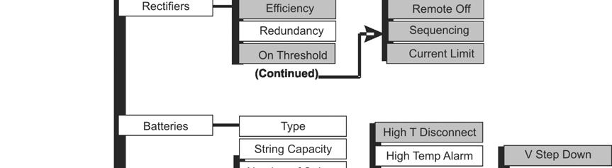


25 Figure 15c: Configuration Menu Map (part 1) Issue 1 May 2010 Page 25 of 34

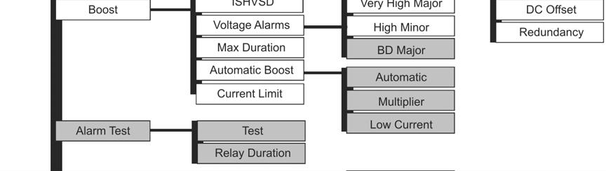
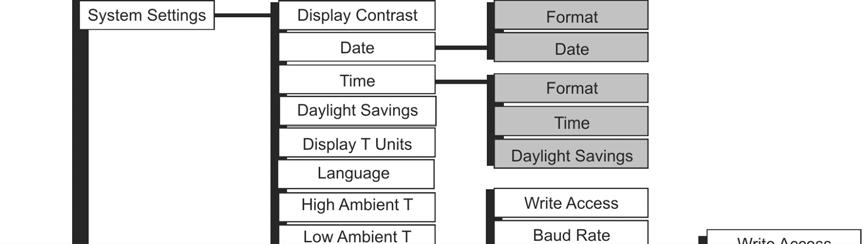
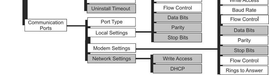
26 Figure 15d: Configuration Menu Map (part 2) Issue 1 May 2010 Page 26 of 34
27 Rectifier Installation All rectifier ac and dc connections are made when rectifiers are installed in the shelf and will power up if ac is applied to the shelf. Step Action 1. Before engaging the rectifier connector into the back of the rectifier slot, press the Latch release button, the latch will spring open. See Figure Firmly push the rectifier into the rectifier slot until the connector on the rear of the rectifier engages with the connector at the back of the rectifier slot on the CPS shelf. The latch will pop most of the way up when the rectifier is properly seated. Push the latch up into the latched position. 3. Repeat until all rectifiers are installed. Figure 16: Rectifier Installation Issue 1 May 2010 Page 27 of 34
28 4 Initial Start-up Verify that all AC, DC and Alarm connections are complete and secure. Once this is complete, the AC input breakers may be turned on. If rectifiers have not yet been installed, install rectifiers now as described in Section 3. As each rectifier is installed, the controller automatically identifies the new rectifier and begins communication. If there are no alarms, make any adjustments to the default settings on the controller that are required for this installation. The following steps cover the minimum configuration of the controller. Refer to the controller sections in CPS6000 Manual ( ) for issues like web pages, craft port and changes to settings. Most functions in software are intuitive by referring to the menu map listed in Section 3. Minimum Configuration Step Action 1. From the default screen, press the Display Menu key to see the Main Menu. 2. Press the down arrow key until Configuration is highlighted, press the Display Menu key and the following selections are available; Float settings, Shunt rating, Rectifier Redundancy, Batteries, Contactors, Boost, System Settings, and Communication Ports. Issue 1 May 2010 Page 28 of 34
29 3. The Float Settings option will be highlighted, press the Display Menu key to access the Float Settings Menu. 4. The Set Point option will be highlighted. Press the Display Menu key to view or change the Float voltage Set Point. Use the left and right arrow keys to adjust the Set Point voltage. Once the Voltage has been set to the desired value Press the Display Menu key to save the change. The voltage range is 42.0 to 56.5 Volts. Factory default is -54.5V. 5. Select Voltage Alarms to set the four Voltage Alarm thresholds. Alarm Very High Voltage Major High Voltage Minor BD (Battery on Discharge) Major Very Low Voltage Major Description Alarm occurs and the unit is shut down when the system detects voltage above its set threshold. The threshold can be set from 50V to 60V in 1V increments. The factory default setting is 57V Alarm indicates an abnormally high output voltage but does not shut the unit down. The alarm threshold can be set from 50V to 60V in 1V increments. The factory default setting is 56V. Alarm occurs when the system is operating either completely or partially on battery power. The alarm threshold can be set from 46V to 55V in 0.1V increments. The factory default setting is 51.0V. Alarm indicates an imminent system shutdown due to discharging batteries or low output voltage. Factory default -46.0V. Issue 1 May 2010 Page 29 of 34
30 5 Troubleshooting Rectifier Alarms The rectifier converts ac to dc power for user equipment. This section describes the rectifier features, functions and alarms. Three LEDs are provided, two green LEDs named AC OK and DC OK, and a red LED named Alarm. Their indications are listed below, followed by complete status descriptions. LEDs: *= On, x=either state AC OK DC OK ALARM Condition Normal Operation * * * * * * Flashing x x Flashing Start Up, Hiccup, Remote Standby High Voltage Shutdown, Thermal Alarm, Internal Failure AC Fail, PFC Fail, Input Fuse, Missing AC, Low Input AC > 15 ms Current Limit Operation Communication Loss Issue 1 May 2010 Page 30 of 34
31 Troubleshooting Chart Controller LED (Note 3) None RED RED RED User Interface Display No response. MIN, AC Fail MAJ, Multiple AC Fail MAJ, Battery on Discharge MAJ, Battery on Discharge Rectifier LEDs (Note 4) AC DC ALM Distribution Module Board LED G G -R- -R- o o o G G o MIN, Rectifier Fail MAJ, Rectifier Fail (Note 1) G o R RED MAJ, Contactor 1 Open RED RED RED RED MAJ, Fuse Major MIN, Rectifier Fail MAJ, Multiple Rectifier Fail MAJ, Battery on Discharge MAJ, High Voltage MAJ, Major Communication Fail G G o -A- G G o R G o R G G G G o G -R- (or missing LVD Board) Possible Problem(s) Controller failure, all devices on the communication bus reporting loss of communication with controller. Multiple rectifiers not receiving ac power, batteries are powering load. AC input circuit breakers have opened. AC input voltage is out of range. Internal rectifier fault. Rectifier output voltage has fallen below the battery on discharge threshold set by the user. All rectifier outputs have dropped below 36V, all rectifiers have entered hiccup mode. Defective controller. One or both of the LVD contactors is open; someone may have manually opened LVD contactor. One or more of the output circuit breakers or fuses have opened. Multiple rectifier thermal alarm: Excessive ambient temperature Multiple rectifier failure High output voltage from rectifier(s) Rectifier(s) high voltage shutdown Internal rectifier(s) failure LVD Board lost communication with the controller. Possible Solution(s) Check controller to ensure it is properly inserted into its slot. If so, perform the following steps: 1. Remove the controller board for 1 minute and then reset. 2. If problem persists, replace controller with new controller board. 3. If problem still persists, call your local field representative. 1. Verify ac power to rectifiers is available. 2. Verify rectifier input circuit breakers are closed. 3. If problem is not corrected, replace rectifiers. If commercial ac power is present but the system voltage remains low, call your local field representative. Investigate other alarms that may be present such as rectifier related problems. Remove controller; if output voltage does not go to set-point previously set by user, call your local field representative. Place disconnect switch in ON position. Reset circuit breakers or replace fuse. 1. Verify that there is no obstruction of the vertical airflow path. 2. Reset rectifies by removing them, waiting approximately 30s and replacing them. 3. If problem persists, replace the rectifiers. 4. If problem still persists, call your local field representative. 1. Reset the rectifier(s) by removing the rectifier(s), waiting approximately 30s and replacing the rectifier(s). 2. If problem persists, replace the rectifier. 3. If problem still persists, call your local field representative. 1. Replace Distribution Module Board. (Note 2) 2. If problem persists, call your local field representative. Issue 1 May 2010 Page 31 of 34
32 Controller LED (Note 3) AMBER AMBER AMBER AMBER AMBER AMBER User Interface Display MIN, AC Fail Rectifier LEDs (Note 4) AC DC ALM o o o MIN, Rectifier Fail (Note 1) G o o MIN, Battery High Temperature G G o MIN, Thermal Probe Fail MIN, Rectifier Fail MIN, Minor Communication Fail (Single Rectifier signaling) G G o G o R -R- Distribution Module Board LED Possible Problem(s) Single Rectifier not receiving ac power. AC input circuit breaker has opened. AC input voltage is out of range. Rectifier output has dropped below 36V, rectifier has entered hiccup mode. Batteries have exceeded temperature threshold set by user. Battery thermal probe failed. Single rectifier thermal alarm: Excessive ambient temperature Multiple rectifier failure Rectifier lost communication with controller. Possible Solution(s) 1. Verify ac power to rectifier is available. 2. Verify rectifier input circuit breaker is closed. 3. If problem not corrected, replace rectifier. Replace rectifier. Call your local field representative. 1. Ensure thermal probe is properly connected to thermal probe cable. 2. Ensure cable is properly connected to the rear of the Distribution Module. 3. If problem persists, replace thermal probe per ensuing instructions. 4. If problem still persists, call your local field representative. 1. Verify that there is no obstruction of the vertical airflow path. 2. Reset the rectifier by removing the rectifier, waiting approximately 30 seconds, and replacing the rectifier. 3. If problem persists, replace the rectifier. 4. If problem still persists, call your local field representative. 1. If a rectifier has been removed from an installed/operational system, go to the Control/Operations menu and execute Uninstall Equipment. 2. Reset the rectifier by removing the rectifier, waiting approximately 30 seconds, and replacing. 3. If problem persists, replace the rectifier. 4. If problem still persists, call your local field representative. Issue 1 May 2010 Page 32 of 34
33 6 Product Warranty A. Seller warrants to Customer only, that: 1 As of the date title to Products passes, Seller will have the right to sell, transfer, and assign such Products and the title conveyed by Seller shall be good; 2 During the warranty period stated in Sub-Article B below, Seller s Manufactured Products (products manufactured by Seller), which have been paid for by Customer, will conform to industry standards and Seller s specifications and shall be free from material defects; 3. With respect to Vendor items (items not manufactured by Seller), Seller warrants that such Vendor items, which have been paid for by Customer, will be free from material defects for a period of sixty (60) days commencing from the date of shipment from Seller s facility. B. The Warranty Period listed below is applicable to Seller s Manufactured Products furnished pursuant to this Agreement, commencing from date of shipment from Seller s facility, unless otherwise agreed to in writing: Warranty Period Product Type New Product Repaired Product Central Office Power Equipment 24 Months 6 Months * The Warranty Period for a repaired Product or part thereof is six (6) months or, the remainder of the unexpired term of the new Product Warranty Period, whichever is longer. C. If, under normal and proper use during the applicable Warranty Period, a defect or nonconformity is identified in a Product and Customer notifies Seller in writing of such defect or nonconformity promptly after Customer discovers such defect or nonconformity, and follows Seller's instructions regarding return of defective or nonconforming Products, Seller shall, at its option attempt first to repair or replace such Product without charge at its facility or, if not feasible, provide a refund or credit based on the original purchase price and installation charges if installed by Seller. Where Seller has elected to repair a Seller s Manufactured Product (other than Cable and Wire Products) which has been installed by Seller and Seller ascertains that the Product is not readily returnable for repair, Seller will repair the Product at Customer s site. With respect to Cable and Wire Products manufactured by Seller which Seller elects to repair but which are not readily returnable for repair, whether or not installed by Seller, Seller at its option, may repair the cable and Wire Products at Customer s site. Issue 1 May 2010 Page 33 of 34
34 D. If Seller has elected to repair or replace a defective Product, Customer shall have the option of removing and reinstalling or having Seller remove and reinstall the defective or nonconforming Product. The cost of the removal and the reinstallation shall be borne by Customer. With respect to Cable and Wire Products, Customer has the further responsibility, at its expense, to make the Cable and Wire Products accessible for repair or replacement and to restore the site. Products returned for repair or replacement will be accepted by Seller only in accordance with its instructions and procedures for such returns. The transportation expense associated with returning such Product to Seller shall be borne by Customer. Seller shall pay the cost of transportation of the repaired or replacing Product to the destination designated by Customer. E. Except for batteries, the defective or nonconforming Products or parts which are replaced shall become Seller's property. Customer shall be solely responsible for the disposition of any batteries. F. If Seller determines that a Product for which warranty service is claimed is not defective or nonconforming, Customer shall pay Seller all costs of handling, inspecting, testing, and transportation and, if applicable, traveling and related expenses. G. Seller makes no warranty with respect to defective conditions or nonconformities resulting from actions of anyone other than Seller or its subcontractors, caused by any of the following: modifications, misuse, neglect, accident, or abuse; improper wiring, repairing, splicing, alteration, installation, storage, or maintenance; use in a manner not in accordance with Seller s or Vendor s specifications or operating instructions, or failure of Customer to apply previously applicable Seller modifications and corrections. In addition, Seller makes no warranty with respect to Products which have had their serial numbers or month and year of manufacture removed, altered, or experimental products or prototypes or with respect to expendable items, including, without limitation, fuses, light bulbs, motor brushes, and the like. Seller s warranty does not extend to any system into which the Product is incorporated. This warranty applies to Customer only and may not be assigned or extended by Customer to any of its customers or other users of the Product. THE FOREGOING WARRANTIES ARE EXCLUSIVE AND ARE IN LIEU OF ALL OTHER EXPRESS AND IMPLIED WARRANTIES, INCLUDING BUT NOT LIMITED TO WARRANTIES OF MERCHANTABILITY AND FITNESS FOR A PARTICULAR PURPOSE. CUSTOMER S SOLE AND EXCLUSIVE REMEDY SHALL BE SELLER S OBLIGATION TO REPAIR, REPLACE, CREDIT, OR REFUND AS SET FORTH ABOVE IN THIS WARRANTY. Issue 1 May 2010 Page 34 of 34
Galaxy Pulsar Plus Controller Family Troubleshooting Table with SMNP Traps
 Critical Power Product Manual Galaxy Pulsar Plus Controller Family Troubleshooting Table with SMNP s This document supplements CC848815341 Galaxy Pulsar Plus Controller Family Product Manual r07. Service
Installation and Operation Manual Low Power (LP) DC Power System
 DC Power System") Installation and Operation Manual Low Power (LP) DC Power System LPS Power Enclosure LPB Battery Enclosure 2051259 R3 Information in this document is subject to change without notice and does not represent
Installation and Operation Manual Low Power (LP) DC Power System LPS Power Enclosure LPB Battery Enclosure 2051259 R3 Information in this document is subject to change without notice and does not represent
QS941A Controller User Interface
 Product Manual Select Code 167-792-184 Comcode CC848816612 Issue 3 November 2009 Notice: The information, specifications, and procedures in this manual are subject to change without notice. Lineage Power
CPS800U Upstream System Telephone Power for Video 48 Vdc Input, ±190 Vdc Output Converter/Limiter System
 CPS800U Upstream System Telephone Power for Video 48 Vdc Input, ±190 Vdc Output Converter/Limiter System Product Manual Select Code 167-793-118 Comcode CC848830927 Issue 1 January 2008 Notice: The information,
Galaxy Pulsar Plus Digital Battery Plant Controller
 Galaxy Pulsar Plus Digital Battery Plant Controller Features Supports up to 60 Power Modules rectifiers and converters Supports dual voltage plants, with rectifiers and converters Auto-sensing dual voltage
Installing the Cisco ONS FAP-4 Fuse Alarm Panel
 Installing the Cisco ONS 15454-FAP-4 Fuse Alarm Panel Product Number: 15454-FAP-4= This document explains how to install, test, operate, and maintain the Cisco ONS 15454-FAP-4 fuse alarm panel. This document
CPS3200U Technical Support Guide
 CPS3200U Technical Support Guide Product Manual Comcode CC848853457 Issue 1 September 2008 7 1 COMPACT POWER LINE SHELVES MODELS J85480S1 AND J2007001 Ordering Guide June 2008 Matrix File # CC848849397-MAN
LORAIN CIP 4890/48120 DC Power System
 DC Power for Business-Critical Continuity Key Features Compact flexibility provides rectifiers, distribution, and controller in one shelf Constant power delivers more current at lower voltages to meet
LORAIN CSP DC Power System
 DC Power for Business-Critical Continuity Key Features Compact flexibility provides more space for revenue generating equipment Constant power delivers more current at lower voltages to meet load or recharge
Galaxy Power System 4848/100 with Dual Rectifier Shelf (GPS 4848/100) H
 H") Galaxy Power System 4848/100 with Dual Rectifier Shelf (GPS 4848/100) H569-434 Note: Instructions in this manual reference installation and setup of the Galaxy Millennium Controller. For Galaxy Millennium
Galaxy Power System 4848/100 with Dual Rectifier Shelf (GPS 4848/100) H569-434 Note: Instructions in this manual reference installation and setup of the Galaxy Millennium Controller. For Galaxy Millennium
Installation Instructions
 50ZPB, C, 50ZHB, C, PA3Z ---A, PH3Z ---A, PA4Z, PH4Z, PAJ4,PHJ4,WJA4,WJH4 SMALL PACKAGED PRODUCTS (SPP) Accessory Electric Heaters 5---20 kw For 14 SEER, R---410A Manufactured Home Installation Instructions
CPS V Cabinet Power System
 4100W (75A) Temperature Hardened System Input: 85 Vac to 264 Vac (Autoranging) Output: -48 Vdc and Optional Ringing Generator H569-422 Battery Plant Model J85500R-1 The low-maintenance, outside-plant integrates
MODEL 8143 SIGNAL SELECTOR INSTALLATION AND OPERATION MANUAL
 MODEL 8143 SIGNAL SELECTOR INSTALLATION AND OPERATION MANUAL 95 Methodist Hill Drive Rochester, NY 14623 Phone: US +1.585.321.5800 Fax: US +1.585.321.5219 www.spectracomcorp.com Part Number 8143-5000-0050
FES - Series Portable Electric Heaters. YES - Series Suspended Electric Heaters CONTENTS
 FOSTORIA INDUSTRIES, INC. A DIVISION OF FES - Series Portable Electric Heaters YES - Series Suspended Electric Heaters (FES-1524-3E shown) IMPORTANT SAFETY INFORMATION INSIDE Serious injury or death possible.
Installation, Operation & Service Manual
 Installation, Operation & Service Manual WARNING Improper installation, adjustment, alteration, service or maintenance can result in death, injury or property damage. Read the Installation, Operation and
Ion Genesis II Pump Controller Digital Level Control with Pump Alternation and High Water Alarm
 Page 1 of 8 General Overview Thank you for purchasing an Ion Genesis controller. Take the time to read the instructions carefully before using this appliance. We strongly recommend that you keep this instruction
Installation Instructions
 50ES--A, 50EZ--A, 50VG--A, B, 50VL--A, B, 50VR--A, 50VT--A, B 604D-- --A, 607C-- --A, B, 607E-- --A, 704D-- --A, 707C-- --A, B, 707E-- --A PA3G -- -- A, PH3G -- -- A, PA4G, PH4G PAD3, PHD3, PAD4, PHD4,
CPS2400U Upstream System 19
 Critical Power Product Manual Upstream System 19 Remote Power System 48 Vdc Input, ±190 Vdc Output Converter/Limiter System Service and Assistance - +1 877 546 3243 or +1 972 244 9288 PE.TechSupport@ge.com
Remote Relay Module (RRM)
") Remote Relay Module (RRM) Instruction Manual WARNING THIS MANUAL MUST BE CAREFULLY READ BY ALL INDIVIDUALS WHO HAVE OR WILL HAVE THE RESPONSIBILITY FOR INSTALLING, USING OR SERVICING THIS PRODUCT. Like
Remote Relay Module (RRM) Instruction Manual WARNING THIS MANUAL MUST BE CAREFULLY READ BY ALL INDIVIDUALS WHO HAVE OR WILL HAVE THE RESPONSIBILITY FOR INSTALLING, USING OR SERVICING THIS PRODUCT. Like
Figure 1. Figure 2. See notes 1 and 2 below.
 273 Branchport Avenue Long Branch, N.J. 07740 (800) 631-2148 Thank you for using our products. www.wheelockinc. com INSTALLATION INSTRUCTIONS HORN SPEAKER WITH AMPLIFIER Use this product according to this
Surge Protective Devices Installation, Operation and Maintenance Manual. LowProfile Series: 080 and 120
 LowProfile Series: 080 and 120 Surge Protective Devices Installation, Operation and Maintenance Manual P.O. Box 3760 Winter Park, FL 32790 USA 1.800.647.1911 www.tpssurge.com LOWPROFILE InstaLLatIOn, OPERatIOn
Noran Tel. FUSE PANEL Technical Practice N NCY 2/2 KLM and 4/4 GMT NEBS Level 3 Certified
 0232-03J December 13, 2006 FUSE PANEL Technical Practice N215112-NCY 2/2 KLM and 4/4 GMT NEBS Level 3 Certified FEATURES 2 isolated groups (busses) of 2 KLM and 4 GMT fuses in each (30Amps/KLM, 15Amps/GMT).
Interrupted Ignition Series Oil Primary Control
 Interrupted Ignition Series Oil Primary Control Application Guide & Installation Instruction for ICM1511*, ICM1512*, ICM151*, ICM1514* For more information on our complete range of American-made products
ion Genesis Pump Controller
 High Water Alarm Document No.: IONG_OM Page 1 of 7 Table of Contents Safety Precautions.......................... 1 General Overview.......................... 1 Installation.................................2
Ion Endeavor Pump Controller Digital Level Control with Pump Alternation and High Water Alarm
 Ion Endeavor Controller Digital Level Control with Alternation Page 1 of 8 General Overview The Ion Endeavor is a pump controller that senses a water level of up to 72", has a configurable water level/pump
FLCH4R Garage and Utility Electric Heater
 FLCH4R Garage and Utility Electric Heater Installation, Operation & Maintenance Instructions Model No. Volts Amps Watts BTU/HR Phase High Low High Low High Low Min Fuse Size* FLCH4R 208 17.3 8.66 3600
Sentry LIQUID LEVEL ALARM MODEL 100 OPERATING MANUAL.
 Sentry LIQUID LEVEL ALARM MODEL 100 OPERATING MANUAL www.aquaticsentry.com TABLE OF CONTENTS 1. SAFETY PRECAUTIONS... 3 2. APPLICATION... 3 2.1 HIGH Liquid Level Alarm 2.2 LOW Liquid Level Alarm 3. INSTALLATION...
FUSE PANEL Technical Practice N N/L9 10/10 GMT NEBS Level 3 Certified
 0226-03K August 13, 2008 FUSE PANEL Technical Practice N250120-N/L9 10/10 GMT NEBS Level 3 Certified FEATURES 2 isolated groups (busses) of 10 GMT fuses in each (15Amps/GMT position). Polarity insensitive
Installation Instructions
 Electric Heaters 5 --- 20 kw SMALL PACKAGED PRODUCTS (SPP) Accessory Electric Heaters For 13 SEER, R---410A Manufactured Home Installation Instructions NOTE: The Dual Point Kit can only be installed on
MaxLite LED High Bay Fixtures
 General Safety Information To reduce the risk of death, personal injury or property damage from fire, electric shock, falling parts, cuts/abrasions, and other hazards read all warnings and instructions
WMWLB / WMWFM / WTWLB / WTWFM Series Hydronic Heating Unit
 January 2008 WMWLB / WMWFM / WTWLB / WTWFM Series Hydronic Heating Unit Installation Operation Maintenance The units are designed for permanent up flow, counter flow, or horizontal left or right airflow
Carbon Monoxide (CO) Detecting Ventilation Fan Controller Model 120VC Single Relay (100/25 PPM) (200/35 PPM)
 Detecting Ventilation Fan Controller Model 120VC Single Relay (100/25 PPM) (200/35 PPM)") Carbon Monoxide (CO) Detecting Ventilation Fan Controller Model 120VC Single Relay 905-0005-01 (100/25 PPM) 905-0005-02 (200/35 PPM) 1. INTRODUCTION Your COSTAR VC carbon monoxide detecting ventilation
Carbon Monoxide (CO) Detecting Ventilation Fan Controller Model 120VC Single Relay 905-0005-01 (100/25 PPM) 905-0005-02 (200/35 PPM) 1. INTRODUCTION Your COSTAR VC carbon monoxide detecting ventilation
FUSE PANEL. Technical Practice N N/L33 10/10 GMT Front Access NEBS Level 3 Certified
 0220-03J Oct 9, 2006 Noran Tel FUSE PANEL Technical Practice N25020-N/L33 0/0 GMT Front Access NEBS Level 3 Certified FEATURES 2 isolated groups (busses) of 0 GMT fuses in each (5Amps/GMT position). Polarity
Sentry LIQUID LEVEL CONTROLLER MODEL 120 OPERATING MANUAL.
 Sentry LIQUID LEVEL CONTROLLER MODEL 120 OPERATING MANUAL www.aquaticsentry.com TABLE OF CONTENTS 1. SAFETY PRECAUTIONS... 3 2. APPLICATION... 3 2.1 HIGH AND LOW LEVEL ALARM 2.2 PUMP DOWN CONTROLLER 2.3
WET/DRY VACUUM. QUEST for Continuous Improvement Windsor s Quality Management System is Certified ISO MODEL: T1. Operating Instructions (ENG)
") WET/DRY VACUUM Operating Instructions (ENG) MODEL: T1 y QUEST for Continuous Improvement Windsor s Quality Management System is Certified ISO 9001. Read these instructions before operating the machine.
WET/DRY VACUUM Operating Instructions (ENG) MODEL: T1 y QUEST for Continuous Improvement Windsor s Quality Management System is Certified ISO 9001. Read these instructions before operating the machine.
1U ULTRA Compact System
 en atel Supervisory Module SM32 Load 60 00 A IE C60947-2 G B140 4 8.2 CHNT NB1-63 C32 23 0/40 0 V e NaT el OK enatel RM 1848 enatel RM 1848 Battery 60 00A IE C60947-2 G B1 4 04 8.2 CHNT NB 1-63 C32 23
Installation Instructions
 50ES---A, 50EZ---A, 50VL---A, 50VG---A, 50VR---A, 50VT---A, 604D--- ---A, 607C--- ---A, 607E,--- ---A, 704D--- ---A, 707C--- ---A, 707E--- ---A PA3G --- --- A, PH3G --- --- A SMALL PACKAGED PRODUCTS Electric
Watt-Muncher Load Bank Manual WATT-MUNCHER. Portable Load Bank. 6 June 2018 Simplex Service Page 1 of 13
 WATT-MUNCHER Portable Load Bank 6 June 2018 Simplex Service 800-637-8603 Page 1 of 13 This manual was last revised: 6 June 2018 For up-to-date information on this product or others, please contact Simplex
Operating & Maintenance Manual. Alert-4 Ethernet LCD Master Alarm
 Operating & Maintenance Manual Alert-4 Ethernet LCD Master Alarm w w w. a m i c o. c o m Contents User Responsibility 4 Introduction 4 Features 5 Description of the Alarm 5 Shipment Details 5 The Alarm
MaxLite Polygon Linear LED Light
 General Safety Information For Contractors: WARNING: Light fixtures should only be installed by qualified electricians. Be sure to use proper mounting method and hardware rated for the weight of the light
ITC 2000 HEATING CONTROL CABINET. Installation & Operation Manual
 ITC 2000 HEATING CONTROL CABINET Installation & Operation Manual VTI, Incorporated 24 McMillan Way Newark, DE 19713 Phone (302) 738 0500 FAX (302) 738 6594 Revision Level 0.03 Manual No. 90003314 June,
SC Installation, Operation & Application Guide
 SC 1800 Manual Changeover Non-Programmable Hardwired Non-Programmable Electronic Thermostat Controls Single Stage Heating Systems Millivolt and Hydronic (water or steam) System Compatible Compatible with
Panel Mounted Heat Exchangers by Dantherm, Inc.
 Panel Mounted Heat Exchangers by Dantherm, Inc. PRODUCT INFORMATION MANUAL C0028 003 Pinnacle OM Manual Rev AB Page 1 of 14 Dantherm, Inc. 110 Corporate Drive, Suite K Spartanburg, SC 29303 Tel # +1 864
Installation Instructions
 Electric Heaters 5 --- 20 kw SMALL PACKAGED PRODUCTS (SPP) Accessory Electric Heaters For 13 SEER, R---410A, Z Chassis Installation Instructions NOTE: Read the entire instruction manual before starting
Syncro Matrix Analogue Addressable Fire Alarm Mimic Panel Product Manual
 Syncro Matrix Analogue Addressable Fire Alarm Mimic Panel Product Manual Australia Issue 01 April 2012 Contents 1 Introduction 3 2 Safety 3 3 Installation 4 3.1 Mounting the Cabinet 4 4 Specifications
Model NT20e Installation Guide
 Model NT20e Installation Guide Rev 1.4 Page 2 of 14 1. Preparing for Installation CAUTION Do not remove the NT20e from the Electro-static bag until instructed from this installation guide. The NT20e is
GASGUARDIAN Channel Controller OPERATING & INSTALLATION MANUAL
 GASGUARDIAN 2 3 2-Channel Controller OPERATING & INSTALLATION MANUAL GasGuardian 2 3 Operating and Installation Manual Table of Contents General description.... 3 Installation. 3 Locating the GasGuardian-2..
Spectron LSN (Life Safety Network) Suggested Specifications
 Suggested Specifications") 1. General 1.1 Scope A Dual-Lite Spectron LSN (Life Safety Network) Series Inverter System shall be furnished to provide a reliable source of power, and shall operate during a utility line deficiency without
1. General 1.1 Scope A Dual-Lite Spectron LSN (Life Safety Network) Series Inverter System shall be furnished to provide a reliable source of power, and shall operate during a utility line deficiency without
AC/DC Power Supply and Battery Charger Installation and Maintenance
 AC/DC Power Supply and Battery Charger Installation and Maintenance 61175043L3-5A Issue 1, January 2004 CLEI Code: SIMPAADA_ CLEI Code: SIMPAAGA_ CONTENTS 1. GENERAL... 1 2. DESCRIPTION... 1 3. INSTALLATION...
5U Compact System. Installation Manual V1.0. Manufactured by Enatel Ltd. 321 Tuam Street PO Box Christchurch New Zealand
 5U Compact System Installation Manual V1.0 Manufactured by Enatel Ltd. 321 Tuam Street PO Box 22-333 Christchurch New Zealand Phone +64-3-366-4550 Fax +64-3-366-0884 Email sales@enatel.net www.enatel.net
Air Pump Up to 800 gallons
 Air Pump Up to 800 gallons REMINDER CALL 1-888-755-6750 BEFORE RETURNING TO STORE. PACKAGE CONTENTS ITEM #PBPAPK40W Questions, problems, missing parts? Before returning to your retailer, call our customer
Use this product according to this instruction manual. Please keep this instruction manual for future reference. MODELS: ST-H15-B & ST-H30
 273 Branchport Avenue Long Branch, N.J. 07740 (800) 631-2148 Thank you for using our products. www.wheelockinc. com INSTALLATION INSTRUCTIONS HORN SPEAKER WITH MULTI-TAP TRANSFORMER Use this product according
Quick Alert Remote (QA216R)
") Quick Alert Remote (QA216R) Description The QA 216 Remote is used by AT&T to monitor tower lights and turned down facilities. It is a 16-bit alarm unit used to transport discrete alarms from a remote location
Quick Alert Remote (QA216R) Description The QA 216 Remote is used by AT&T to monitor tower lights and turned down facilities. It is a 16-bit alarm unit used to transport discrete alarms from a remote location
Environmental Monitoring SmartSlot Card
 Environmental Monitoring SmartSlot Card AP9612TH Installation and Quick Start Manual Contents Introduction............................. 1 Overview 1 Product inventory 1 Safety notice 2 Your inspection
IFS Fiber Module Installation & Operation Instructions
 VT6010 VT6010-R3 VR6010 VR6010-R3 IFS Fiber Module Installation & Operation Instructions P/N 1062796 REV B ISS 01JUL11 4 BNC Cables (Input from cameras) VT6010A 4 CHANNEL VIDEO TRANSMITTER 1-2 - VIDEO
Isolation Relay: If Needed. # 9. NO relay for TT To Thermostat NO relay. MZ308 Exquisite Heat Controller
 #4. 24 Volt AC & for 24 AC supply to thermostat if needed Isolation Relay: If Needed. # 9. NO relay for TT To Thermostat NO relay #12. To Thermistor for Domestic hot water Supply from boiler Orange & Brown
UltraLITE Model ELU Centralized Emergency Lighting Inverter 4.2 KW- 5 KW
 12/23/16 Rev 9 UltraLITE Model ELU General Specification 4.2 KW to 5 KW UltraLITE Model ELU Centralized Emergency Lighting Inverter 4.2 KW- 5 KW 1.0 General General Specification This specification describes
FUSE PANEL. Technical Practice N N/0803 5/5 GMT Front Access NEBS Level 3 Certified
 0803-03B April 17, 2008 Noran Tel PANEL Technical Practice N250110-N/0803 5/5 GMT Front Access NEBS Level 3 Certified FEATURES 2 isolated groups (busses) of 5 GMT fuses in each (15Amps/GMT position). Polarity
Revision: None DCN No. First Issue Date: November 30, 1998 Product: Standard DCT, 120-volts
 Figure 1Document: SPEC-112 Revision: None DCN No. First Issue Date: November 30, 1998 Product: Standard DCT, 120-volts construction requirements of UL approved Class H (180 C) insulation system. Transformers
Operating Instructions. Temperature and Humidity EC Control. Model 35YV93
 Operating Instructions EN Temperature and Humidity EC Control Model 35YV93 479702 PLEASE READ AND SAVE THESE INSTRUCTIONS. READ CAREFULLY BEFORE ATTEMPTING TO ASSEMBLE, INSTALL, OPERATE OR MAINTAIN THE
GG-2 2-CHANNEL GAS DETECTION CONTROL PANEL. Installation and Operation Manual
 GG-2 2-CHANNEL GAS DETECTION CONTROL PANEL Installation and Operation Manual 2 GG-2 Warning Use this product only in the manner described in this manual. If the equipment is used in a manner not specified
ELECTRIC FIREPLACE HEATER WITH SINGLE GLASS DOOR
 ELECTRIC FIREPLACE HEATER WITH SINGLE GLASS DOOR Model 91797 ASSEMBLY and Operating Instructions Visit our website at: http://www.harborfreight.com Read this material before using this product. Failure
IFS Fiber Module Installation & Operation Instructions
 VAT1200 VAT1200-R3 VAR1200 VAR1200-R3 IFS Fiber Module Installation & Operation Instructions P/N 1062830 REV B ISS 01JUL11 NOTE: For an unbalanced audio input connection tie pin 1 to pin 2 and utilize
CurrentGuard TM. Installation, Operation and Maintenance Manual. CurrentGuardTM. Flush Mount. Surge Protective Devices A00
 TM CGFS u r g e P R O T E C T I O N CurrentGuardTM Installation, Operation and Maintenance Manual 750-0098-006 A00 Surge Protective Devices CurrentGuard TM Flush Mount Table of Contents Guide to Installation
Advantium 16 System Monitor
 ADI 9531-D Advantium 16 System Monitor INSTALLATION AND OPERATING INSTRUCTIONS Carefully Read These Instructions Before Operating Carefully Read These Controls Corporation of America 1501 Harpers Road
Proliphix Thermostat Installation Guide. Release 2.0
 Proliphix Thermostat Installation Guide Release 2.0 July 2006 Beta Draft Confidential Technical Support When contacting Proliphix for technical assistance, please have the following information available:
Public Safety DAS Annunciator Panel
 Public Safety DAS Annunciator Panel 120 VAC Models: 1221-A, 1221-B, 1221-C Revision D 91117 48 VDC Models: 1221-A-48, 1221-B-48, 1221-C-48 24 VDC Models: 1221A-24, 1221-B-24, 1221-C-24 CAUTION: (Read This
IMPORTANT SAFETY INFORMATION
 OPERATION INSTALLATION PARTS MANUAL www.fostoriaindustries.com Made in U.S.A. ELECTRIC PORTABLE HEATER FES-1024-1CA 08860010 YES-1024-1CA 08861510 FES-1520-3A 08860110 YES-1520-3A 08860810 FES-1524-1A
MaxLite LED MICRO-T PANEL
 ` Installation Instructions General Safety Information To reduce the risk of death, personal injury or property damage from fire, electric shock, falling parts, cuts/abrasions, and other hazards read all
Table of Contents. Features Quality Policy Section A - Unit Operation Section B Unit Maintenance Trouble Shooting Guide...
 Table of Contents Features... 3 Quality Policy... 3 Section A - Unit Operation... 4 Section B Unit Maintenance... 6 Trouble Shooting Guide... 7 Wiring Diagram... 9 Section C Unit Installation... 9 Unit
EOS. Instruction Manual. 120V High Amperage Digital Humidity Controller. Part #
 EOS 120V High Amperage Digital Humidity Controller Instruction Manual Part # 702603 www.titancontrols.net 120V High Amperage Digital Humidity Controller Warnings and Cautions Factory Settings Eos 120V
STATUS ALARM ALARM HISTORY POWER HISTORY RESET
 Instruction Manual Model 1582-70L2 RF Switch June 2011, Rev. D CH1 AUTO CH2 SWITCH 1 2 1 2 STATUS 1 2 MODEL 1582 SWITCH CROSS TECHNOLOGIES INC. CH1 ONLINE MANUAL SELECT CH2 SWITCH MANUAL REMOTE ONLINE
RAM3 Remote Alarm Module
 RAM3 Remote Alarm Module INSTRUCTIONS Installation and Operation of the AMC-RAM3 with AMC Monitors IMPORTANT: Please read this installation and operating instructions completely and carefully before starting.
IFS Fiber Module Installation & Operation Instructions
 D1300 D1300-R3 D2300 D2300WDM D2300CP D2300SHR IFS Fiber Module Installation & Operation Instructions P/N 1062852 REV ISS 01AUG11 D1300 / D2300 / D2300SHR 2 - Wire RS485 Connection 4 3 2 1 No Connection
AV17 Series Switch-Tek Manual Direct and Remote Drum Mount Float Alarm 17 SEPT 08 Rev A
 AV17 Series Switch-Tek Manual Direct and Remote Drum Mount Float Alarm 17 SEPT 08 Flowline, Inc. 10500 Humbolt Street Los Alamitos, CA 90720 Tel: (562) 598-3015 Fax: (562) 431-8507 www.flowline.com 17
TOUCHDOWN 48 CEILING FAN
 TOUCHDOWN 48 CEILING FAN MODEL #50205 Español p. 20 Questions, problems, missing parts? Before returning to your retailer, call our customer service department at 1-877-361-3883, Monday - Thursday, 8 am
Controllers. Instruction Manual WARNING
 Controllers Instruction Manual WARNING THIS MANUAL MUST BE CAREFULLY READ BY ALL INDIVIDUALS WHO HAVE OR WILL HAVE THE RESPONSIBILITY FOR INSTALLING, USING OR SERVICING THIS PRODUCT. Like any piece of
GigaCore 12. Gigabit Ethernet Switch for the entertainment industry. Quick Start Guide. V2.1.0 Rev5. English
 GigaCore 12 Gigabit Ethernet Switch for the entertainment industry Quick Start Guide V2.1.0 Rev5 English Table of Content Safety Instructions 3 Compliance information 4 Warranty information 5 Registration
Installation Manual. Model 200QF 8/8 Model 200QF 8/ DC Edge III
 Installation Manual Model 200QF 8/8 Model 200QF 8/8 +24 DC Edge III Model 200QF 8/8 +24; Model 200QF 8/8 Part# 1101-1006 (Positive Polarity); 1101-1051 (Negative Polarity) Installation Manual DC Edge III
Power Conditioners User s Manual. For use with Standard Power Conditioners, Medical Power Conditioners and Ground Guard Power Conditioners
 Power Conditioners User s Manual For use with Standard Power Conditioners, Medical Power Conditioners and Ground Guard Power Conditioners TABLE OF CONTENTS 1.0 - Introduction... 4 2.0 - Safety Instructions...
GAS MONITOR Model Model
 Sierra Monitor Corporation 1991 Tarob Court, Milpitas, CA 95035 (408) 262-6611 (800) 727-4377 (408) 262-9042 - Fax E-mail: sierra@sierramonitor.com Web Site: www.sierramonitor.com GAS MONITOR Model 2350-00
Max HT Air Heater FOR SAFETY & LONG HEATER LIFE, CAREFULLY READ THIS MANUAL BEFORE USE.
 Max HT Air Heater FOR SAFETY & LONG HEATER LIFE, CAREFULLY READ THIS MANUAL BEFORE USE. Safety SHOCK HAZARD! Only qualified individuals should install this heater and related controls. Follow all applicable
2. All connections are 24 volt AC. Verify all planned connections at TT thermostat connections, before turning on power
 .1. Turn off all power to the boiler at the circuit breaker. This will avoid accidental injury, or short circuits. 2. All connections are 24 volt AC. Verify all planned connections at TT thermostat connections,
ACCURATE ELECTRONICS INC PO BOX SW HALL BLVD BEAVERTON OR USA FAX
 Page 1 of 10 Model 10807800 January 2014 ACCURATE ELECTRONICS INC PO BOX 1654 97075-1654 8687 SW HALL BLVD 97008 BEAVERTON OR USA 503.641.0118 FAX 503.646.3903 WWW.ACCURATE.ORG Practice Section 10807800
Static Pressure Control
 The (model SPC-2) is a fully programmable controller that provides extensive flexibility for your curtain or awning control needs. The SPC-2 automatically controls the pressure in a room by operating a
Bulletin 1608N MiniDySC Dynamic Sag Corrector
 User Manual Bulletin 1608N MiniDySC Dynamic Sag Corrector Single Phase Voltage Sag Correction 2...6 Amps (250...750 VA) Important User Information Solid-state equipment has operational characteristics
Installation Instructions
 EHNA Electric Heaters 5-20kW For 60 Hz Small Packaged Products MODELS: PAD3, PHD3, PAD4, PHD4, PAD5, PHD5, WPA3, WPH3 Installation Instructions NOTE: Read the entire instruction manual before starting
Installation Manual COPYRIGHT NOTICE
 Installation Manual COPYRIGHT NOTICE Copyright 2007 by Quest Controls Inc (QUEST). The material discussed in this publication is the proprietary property of QUEST. QUEST retains all rights to reproduction
SECTION P01 LIGHTING AND APPLIANCE PANELBOARDS - A-SERIES
 PART 1 GENERAL A. The requirements of the Contract, Division 1, and Division 16 apply to work in this Section. 1.01 SECTION INCLUDES A. Lighting and appliance panelboards 1.02 RELATED SECTIONS A. 16475,
Models NFPA 1221-A, NFPA 1221-B Public Safety DAS Annunciator Panel. Revision E 61117
 Models NFPA 1221-A, NFPA 1221-B Public Safety DAS Annunciator Panel Revision E 61117 CAUTION: (Read This First) This panel has been designed to make it nearly bullet proof to mistakes made when wiring
INSTALLATION INSTRUCTIONS MODEL PA-250 AND PA-500 BOOSTER AMPLIFIER
 273 Branchport Avenue Long Branch, N.J. 07740 (908) 222-6880 INSTALLATION INSTRUCTIONS MODEL PA-250 AND PA-500 BOOSTER AMPLIFIER GENERAL: The Series PA-250 and PA-500 Watt Booster Amplifiers are designed
MAYFIELD CEILING FAN LISTED E ITEM # MODEL #BTH44ABZC5C BTH44BNK5C Español p. 20 ATTACH YOUR RECEIPT HERE.
 Harbor Breeze is a registered trademark of LF, LLC. All Rights Reserved. ITEM #0331094 0331096 MAYFIELD CEILING FAN MODEL #BTH44ABZC5C BTH44BNK5C Español p. 20 ATTACH YOUR RECEIPT HERE Serial Number Purchase
Installation and Operating Instructions ISH ELECTRIC STEAM SUPERHEATER
 Installation and Operating Instructions ISH ELECTRIC STEAM SUPERHEATER 1 Installation and Operating Instructions ISH ELECTRIC STEAM SUPERHEATER FOR YOUR SAFETY This manual supplies information on the application,
RELEASE DEVICES RELEASE DEVICE-WPS MODELS A/B INSTALLATION MANUAL U.L. LISTED CANADIAN LISTED CSFM: :100 GENERAL DESCRIPTION:
 RELEASE DEVICES MADE IN THE U.S.A. RELEASE DEVICE-WPS MODELS A/B INSTALLATION MANUAL U.L. LISTED CANADIAN LISTED CSFM: 7300-1418:100 GENERAL DESCRIPTION: S/N: The "WPS" World Power Series, Time Delay Release
Henny Penny Island Warmer Model HMI-103 Model HMI-105 TECHNICAL MANUAL
 Henny Penny Island Warmer Model HMI-103 Model HMI-105 TECHNICAL MANUAL THIS PAGE INTENTIONALLY LEFT BLANK. Section TABLE OF CONTENTS Page Section 1. TROUBLESHOOTING... 1-1 1-1. Introduction... 1-1 1-2.
ELSTON 52 CEILING FAN
 ELSTON 52 CEILING FAN MODEL #10290 Español p. 21 Questions, problems, missing parts? Before returning to your retailer, call our customer service department at 1-877-361-3883, Monday - Thursday, 8 am -
380 SERIES REMOTE SIREN ETSA380R
 ! WARNING Sirens produce loud sounds that may damage hearing: - Roll up windows. - Wear hearing protection. - Use only for emergency response. - Avoid exposure to siren sound outside of vehicle. Please
INSTALLATION MANUAL. PP1 Ozone System Designed for use within pool skimmer
 PP1 Ozone System Designed for use within pool skimmer PERFECT POOL OZONE GENERATOR! NOTE TO INSTALLER: GIVE THIS MANUAL TO OWNER OPERATOR AFTER INSTALLATION SAFETY PRECAUTIONS! IMPORTANT SAFETY INSTRUCTIONS
SERIES PSE-690 INSTALLATION & OPERATION MANUAL IMPORTANT: PSE-690 REMOTE STROBE POWER SUPPLY
 INSTALLATION & OPERATION MANUAL PSE-690 REMOTE STROBE POWER SUPPLY SERIES PSE-690 REMOTE STROBE POWER SUPPLY IMPORTANT: Read all instructions and warnings before installing and using. INSTALLER: This manual
PodView Level Indicator LI40 Series Manual
 PodView Level Indicator LI40 Series Manual Flowline Inc. 10500 Humbolt Street Los Alamitos, CA 90720 Tel: (562) 598 3015 Fax: (562) 431 8507 www.flowline.com Rev A MN204260 1 of 16 INTRODUCTION / TABLE