-Tag. BodyGuard. Driver Awareness System SAFETY SOLUTIONS. Installation Guide. BodyGuard Safety Solutions A division of Orbit Communications Pty Ltd
|
|
|
- Violet Clarke
- 5 years ago
- Views:
Transcription


1 Installation Guide Safety Solutions A division of Orbit Communications Pty Ltd Page 1
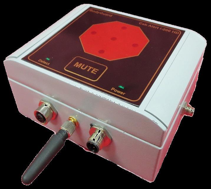
2 Introduction This Guide provides information to assist with installation and use of the i proximity detection and warning system. The document begins with an overview of the system and then describes the wiring connections for both single sensor and dual sensor systems. An explanation is given for installation and running the simple configuration utility that enables changes to the detection zone distances and speaker volume using a Bluetooth connection between computer systems. Overview The system improves safety by increasing driver awareness when pedestrians are too close to the vehicle. The system comprises a Cab Alert unit, Speaker and one or more sensor units. The Sensor Unit receives information from pedestrian Tag devices, process and transfer information to the Cab Alert unit. The Cab Alert Unit processes information from all sensors and determines whether a Tag detection has occurred within the detection zone of any Sensor unit fitted. The Cab Alert unit provides an Audible alarm (alert followed by human voice notification) as well as visual warning. In addition to the Alarm functions, the Cab Alert manages installation and removal of sensor units, storage of all detection and system events and facilitates Bluetooth communication between the Cab Alert unit and computer. Safety Solutions A division of Orbit Communications Pty Ltd Page 2
3 Wiring The sensor units connect to the Cab Alert unit by 4-core cable. The standard length cable supplied is 5m per sensor. (Longer length cable available upon request in 5m increments). The 4-core cable has two shielded-twisted pairs in addition to overall shielding. The recommended maximum cable length between the Cab Alert unit and a sensor unit is 200m.The 4-core cable is terminated at each end using M12, Male circular plugs. The cable wiring connection is straight-through (Pin 1 at one end connects to pin one at other end and so forth). The Power (pins 1 and 2 ) should connected to one of the twisted pairs and data signals (pins 2 and 3 ) to the other twisted pair. Dual sensor systems are supplied with a Y splitter cable that enables the 2 sensors to plug into the one Cab Alert unit connector. The supplied cable is Alpha Wire 2466C or 1243/2C. Safety Solutions A division of Orbit Communications Pty Ltd Page 3


.")
4 Fitting M12 circular male plugs to 4-core cable 1) Loosen Hexagonal plastic nut at bottom of plug by rotating ant-clockwise. 2) With rear nut unfastened, hold knurled plastic ring near metal ring with one hand and turn plastic body of plug anticlockwise with other hand. 3) Use a screwdriver to fasten ends of cable to the terminals inside the plug head IMPORTANT: Be careful to ensure correct wiring of plug. The signals are connected to pins as shown below at BOTH ends of the cable (i.e. Straight-Through connection). Wire colouring Pin 1: Red Pin 2: White Pin 3: Green Pin 4: Black RED/Black = shielded twisted pair White/Green = shielded twisted pair Safety Solutions A division of Orbit Communications Pty Ltd Page 4
5 Power Supply The system comes with 2m length power cable, fitted with moulded M12 female 4-core cable to plug into Cab Alert Unit and flying leads at other. The system connects to +12V or +24V DC supply via 2A fuse. Voltage above 24V requires a Voltage Reducer to lower voltage into range 12-24V DC. The Cab Alert unit receives power from the vehicle electrical system, Sensor units receive power from the Cab Alert connector. Power Cable connections Pin 1: +12V DC Power Supply Input (Brown) Pin 2: Ignition Sense (White) Pin 3: Switched output (Blue) Pin 4: Ground/Earth (Black) Power Supply wiring Examples The system operates from the vehicle s 12V or 24V DC power supply. If the vehicle s supply voltage is higher than 24V DC, then a voltage reduce is required. When logging is required, Ignition Sense connects to the ignition switch. When logging is not required, Ignition Sense connects to 12V DC input signal. IMPORTANT: Tag Detection will only occur when the WHITE Ignition Sense wire connects to the supply voltage. 12/24V DC supply, NO logging Safety Solutions A division of Orbit Communications Pty Ltd Page 5

6 12/24V DC supply, with Data Logging Higher than 24V DC supply, NO logging Safety Solutions A division of Orbit Communications Pty Ltd Page 6
7 Higher than 24V DC supply, with logging Safety Solutions A division of Orbit Communications Pty Ltd Page 7
8 Switched Output The Cab Alert unit provides an Open Drain (floating) output. This output pulls to ground whenever the alarm is active. This low current output (less than 100mA capacity) controls an external relay that can switch other equipment or devices during Tag detection. An external relay can be connected to control warning devices or lockout controls. A protection diode (such as 1N4001 or 1N4007) should be placed across the relay control coil as shown. Safety Solutions A division of Orbit Communications Pty Ltd Page 8
. All cables exit from the bottom of the enclosure.")
.")
9 Cab Alert Location The Cab Alert unit mounts inside the driver cab within view of the driver. The speaker mounts in any convenient location (keep speaker location at least 300mm away from location of driver s ear). All cables exit from the bottom of the enclosure. There is no requirement to leave space around top or sides of the enclosure. Leave at least 150mm left below the enclosure to enable cables to exit the enclosure without excessive bending. The supplied pivot mounting bracket enables the cab alert unit to be mounted in any orientation and then rotated to best viewing angle (for instance, it can be mounted on the roof of the vehicle). The Pivot mount bolts to the back of the Cab Alert enclosure using four M5 x 16mm bolts. Be careful to ensure the unit does not interfere with driver movement or obstruct the view. Important: Use only M5 x 16mm bolts for pivot mount. Ensure no more than 10mm thread extends into the Enclosure when bolts fastened. If the pivot is not used then ensure that the thread of bolts used does not extend more than 10mm into the enclosure. Safety Solutions A division of Orbit Communications Pty Ltd Page 9
10 Sensor Location The detection zone range is the distance from the actual Sensor unit to the Tag device. The Range is adjustable from minimum setting of around 2.5m to maximum setting around 9m. The 4-way switch inside sensor unit is used to adjust range. The Sensor unit mounts either horizontally or vertically. The shape of the detection zone is slightly oval around the vehicle when sensor is located horizontally and is almost circular when mounted vertically. The choice of mounting orientation is dependent on the application. The horizontal orientation is good for applications where more detection may be required at front and rear with less range at sides. The vertical orientation is best when a uniform zone is required. These characteristics of the Sensor detection zone shape can be used to advantage in various applications. For instance, a large vehicle may require long distance at front and rear. In this case, a front and rear sensor placed horizontally with edges of sensor pointing to sides, would give best front and rear range turning the horizontal sensor 90 degrees would give better range at sides and less at front and rear. Vertical mounted sensor on a smaller vehicle (such as a forklift) may give better allround cover. The optional Install Kit comes with magnetic mounting brackets for ease of installation. M5 x 8mm bolts secure the magnets to the mounting brackets. Leave as much free space gap between sensor and surrounding metal as possible. This will optimise sensor performance. If the magnetic mounting is not used, avoid mounting base of sensor directly to metal surface. In this case, try to mount sensor at least 30mm above the surface. Free space Free space Free space Free space At least 40mm if not using supplied magnets Free space Safety Solutions A division of Orbit Communications Pty Ltd Page 10

11 Horizontal Sensor Location The large Red donut image below approximates the expected detection zone shape relative to the location of the sensor unit with sensor unit mounted horizontally. The maximum zone distance is perpendicular to the long side of the sensor unit while the shorter side is at the sides looking into the end of the sensor unit. The shorter side may be around 80-85% of the long side distance. The image at the right shows top view of vehicle with sensor horizontal and the approximate zone around the outside of the vehicle. (Assuming Tag worn in vertical orientation). 9m Max. Distance 8m 80-90% distance Approximate 3D Detection zone pattern Aerial View This image demonstrates the effect of placing sensor horizontally for detection zone pattern. Actual distance may be vary. Safety Solutions A division of Orbit Communications Pty Ltd Page 11
 pattern, however, the maximum range in this orientation may be slightly less due to approach around vehicle being made on short axis.")
12 Vertical Sensor Location A vertically mounted Sensor unit produces vertical donut shaped detection zone. The long axis is up and down while the short axis is around the vehicle. This orientation produces the most uniform (almost circular) pattern, however, the maximum range in this orientation may be slightly less due to approach around vehicle being made on short axis. 8m 8m Approximate 3D Detection zone pattern Aerial View This image demonstrates the effect of placing sensor vertically for detection zone pattern. Actual distance may be vary Safety Solutions A division of Orbit Communications Pty Ltd Page 12
13 Front and Rear Horizontal Sensor Orientation The example below illustrates how multiple sensors provide extended range at front and rear of larger vehicle with Sensors mounted horizontally. Distances shown are indicative to highlight shape of zone only. 9m 8m 8m 10m Safety Solutions A division of Orbit Communications Pty Ltd Page 13
14 Front and Rear Vertical Sensor Orientation The example below illustrates how multiple sensors provide extended range at front and rear of larger vehicle when sensors mounted vertically. Distances shown are indicative to highlight shape of zone only. 8m 8m 8m 8m Safety Solutions A division of Orbit Communications Pty Ltd Page 14
15 Detection Zone distance setting The range of the detection is set using the 4-way switch inside the sensor unit. (Note: The Lid is connected to the base by cable, be careful not to stretch cable).the values shown below are approximate distance settings. The table below provides a guideline for initial zone range setting. Test the system by walking in and out of zone with Tag and then adjust range up or down as required until desired range achieved. (Do NOT open lid when water can enter and ensure lid fastened securely after distance adjusted) Range Setting Switch (LEFT =, RIGHT = ) Distance Maximum Switch 1 Switch 2 Switch 3 Switch 4 Sensor ID The sensor can be assigned an ID from 0 to 15 (Characters A through F represent values 10 through 15 ) using the rotating selection switch inside the Sensor unit. This switch sets the location of the sensor on the vehicle. Single system Sensors and dual Front Sensors; set ID = 0. Dual system Rear Sensors; set ID = 1. NOTE: Single system MUST have Sensor ID set to 0. E F Front Rear Safety Solutions A division of Orbit Communications Pty Ltd Page 15
16 Alert Speaker Volume The volume of the speaker has 16 levels of adjustment from softest to loudest setting. The adjustment is made by changing setting on the rotary switch inside the Cab Unit. Access to the Cab unit is achieved by pulling up the plastic side covers from the lid by hand to reveal the 4 fastening bolts. Undo the 4 bolts to remove the lid. The lid is connected to the base of the Cab Alert unit by thin cable, be careful not to stretch the cable when removing the lid. The minimum setting is 0. Increase volume by moving switch CLOCKWISE (maximum setting is F ) and software by turning anti-clockwise. The alert will sound each time the switch is changed, this provides an indication of the new volume setting. E F Configuration software Refer to configuration and log management device User guide. System Operation Power Up At power up the system will flash warning LEDs, turn on POWER LED and provide system start up voice notifications. Communication with each fitted sensor is checked and voice notification given. Example; Front Tag Sensor OK, Rear Tag Sensor OK (for dual system) Tag Sensor OK for single sensor system (single system) No Front Sensor Found or No Rear Sensor Found (dual system) No Sensors Found (single system) Once the system has started without error, the Cab alert unit will begin communication with the sensor units. Valid responses from the sensor units cause the Detect LED on the front panel to blink. During normal operation, Detect LED should be blinking non-stop. Power Down If the Ignition Sense is used, the Power Led will remain after vehicle ignition switches off. The system can connect to handheld configuration and log device management in this mode. When ignition is switch back on, the system will power up and start detection. Safety Solutions A division of Orbit Communications Pty Ltd Page 16
 will begin to flash.")

17 Alarm Activation A Tag detected within the detection zone of a sensor unit causes an audible alarm to sound, followed by a human voice indication of the risk. For a single sensor system Look Out! Person near you. For dual sensor system Look out! Person in front of you or Look Out! Person behind you. The high brightness LEDs on the front panel (in the shape of a STOP sign) will begin to flash. The siren will repeat approximately every 5 seconds while the Tag remains in the detection zone, and the LEDs will continue to flash. When the Tag leaves the detection zone, the LEDs will stop flashing and siren will cease. The alarm takes around 1 second to stop after Tag leaves the zone. Mute If the driver presses the mute switch while an alarm is active, a voice will advise Speaker Muted and the repeating siren will cease. The LEDs will remain flashing as long as the Tag is still in the detection zone. If the Tag leaves the zone OR another Tag enters, then the alarm resets and starts again automatically. The driver cannot permanently mute the speaker. Driver Tag Lockout The Driver Tag Lockout is a feature that enables the driver to wear a Tag without activating his or her own vehicle alarm. Two methods are available: 1. Press and hold MUTE button longer than 3 seconds, while alarm is active. The driver Tag must be only tag in detection zone. This method works ok for intermittent use but not recommended for long-term use due to higher battery consumption. Use Rechargeable Tags for long-term use. The Driver Tag will UNLOCK automatically when the vehicle is switched off, ensuring the Tag cannot permanently lock out. 2. Tag Disable Pouch. This pouch mounts to the vehicle. Tags disable while in the pouch and automatically enable when removed. The driver places the Tag into pouch when operating the vehicle and then removes the Tag when leaving the vehicle. Safety Solutions A division of Orbit Communications Pty Ltd Driver Tag Disable Pouch Page 17
18 Safety Precautions Observe the following safety precautions whenever the system is in operation or in service. Failure to comply with these precautions violates the safety standards of the design, manufacture and intended use of the product. Important proximity detection and warning system is intended to be an aid to the driver and is not intended in any way to replace existing safety processes or remove or minimise the driver s diligence and/or duty of care. The Bodyguard system receives and transmits radio frequency energy while switched on, therefore interference may occur if the system is located near TVs, radios, PCs or any inadequately shielded equipment. Due to the nature of wireless systems, transmission and reception of data will not guaranteed. Data may be corrupted (i.e. Have errors) or be totally lost at certain times due to the environment, other machinery or malfunction of electronic components. Significant loss of data is rare when wireless devices, such as the system, used normally. The system should not be used in situations, or in any manner, where failure to transmit or receive data could result in damage of any kind to the user or any other party, including but not limited to personal injury, death or loss of property. Orbit Communications Pty Ltd accepts no responsibility for damages of any kind resulting from errors in data transmitted or received using the systems, or for the failure of the system to transmit or receive such data. Do not operate the system in areas where blasting is in progress, where explosive atmospheres may be present, near medical equipment, near life support equipment, or any equipment which may be susceptible to any form of radio interference, in such areas, system must be powered. Do not operate system in any aircraft, whether the aircraft is on the ground or in flight. In an aircraft, the system must be. The information in Orbit Communications Pty Ltd documents are subject to change without notice and do not represent a commitment on the part of Orbit Communications Pty Ltd. Orbit Communications Pty Ltd and its affiliates specifically disclaim liability for any and all direct, indirect, special, general, incidental, consequential, punitive or exemplary damages including, but not limited to, loss of profits or revenue or anticipated profits or revenue arising out of the use or inability to use any Orbit Communications Pty Ltd product, even if Orbit Communications Pty Ltd and/or its affiliates have been advised of the possibility of such damages or they are foreseeable or for claims by any third party. Notwithstanding the foregoing, in no event shall Orbit Communications Pty Ltd and/or its affiliates aggregate liability arising under or in connection with the Orbit Communications Pty Ltd product, regardless of the number of events, occurrences or claims giving rise to liability, be in excess of the price paid by the purchaser for the Orbit Communications Pty Ltd product. Safety Solutions A division of Orbit Communications Pty Ltd Page 18
19 WEEE directive 2002/96/EC, disposal of old electronic equipment This product shall not be treated as household waste. It must be placed at an appropriate collection point for the recycling of electrical and electronic equipment. By ensuring the correct disposal of this equipment, it will help the environment and human s health. The recycling will help to conserve the natural resources. Do NOT Dispose of Personnel TAG units (i-tags) in a fire, furnace or other extreme heat source. These units contain lithium batteries that may explode when exposed to extreme temperature. CAUTI Always remove battery connection before starting work on equipment to eliminate the risk of short circuit. Fuse type is 3AG, 2A, Slow-Blow. Make sure correct fuse installed before applying power to system. Ensure fuse is replaced with specified type and rating only. Ensure power removed from fuse before attempting to replace (Ignition switched ). Ensure cause of fuse blowout fixed before replacing fuse. Ensure Power supply input voltage to unit is within the range specified for the model (12V DC to 28V DC for standard model), (12V DC to 90 VDC when used with voltage reducer). Ensure that Cab Alert and Speaker unit are connected to chassis ground. Be careful to mount the Components of the system in such a manner as to ensure the unit does not obstruct the driver s field of vision or interfere with driver movement required for safe operation the vehicle. The speaker should not be mounted close in a position where the sound can be clearly heard in event of a proximity detection but no so close as may prevent the driver from hearing other sounds or may potentially cause damage to hearing. The speaker should mount a minimal distance of 300mm (12 ) away from either of the operator s ears. Cleaning Clean using a soft cloth dampened in mild detergent and water. Do NOT use chemicals or cleaners containing harsh materials such as benzene, xylene and acetone. Safety Solutions A division of Orbit Communications Pty Ltd Page 19
20 Certificate Information C-Tick N15294 FCC Cab Alert Unit contains FCCID S7AIW02 Sensor Unit: FCC Rule: Part 15 Subpart C Section , FCCID. Tag Device: FCC Rule: Part 15 Subpart C Section , FCCID This equipment has been tested and found to comply with the limits for a Class B digital device, pursuant to Part 15 of the FCC Rules. These limits are designed to provide reasonable protection against harmful interference in a residential installation. This equipment generates uses and can radiate radio frequency energy and, if not installed and used in accordance with the instructions, may cause harmful interference to radio communications. However, there is no guarantee that interference will not occur in a particular installation. If this equipment does cause harmful interference to radio or television reception, which can be determined by turning the equipment off and on, the user is encouraged to try to correct the interference by one or more of the following measures: - Reorient or relocate the receiving antenna. Increase the separation between the equipment and receiver. Connect the equipment into an outlet on a circuit different from that to which the receiver is connected. Consult the dealer or an experienced radio/tv technician for help. This device complies with part 15 of the FCC Rules. Operation is subject to the following two conditions: (1) This device may not cause harmful interference, and (2) this device must accept any interference received, including interference that may cause undesired operation. Changes or modifications not expressly approved by the party responsible for compliance could void the user's authority to operate the equipment. Safety Solutions A division of Orbit Communications Pty Ltd Page 20
Home Doorway Alert Kit
 READ ME FIRST DIY WIRELESS ALERT Home Doorway Alert Kit EN Instruction Manual 2 About this Manual The content in this manual is for information purposes only and is subject to change without notice. While
Ambient Weather WS-091-C Three Channel Display Wireless Thermometer (Console Only) User Manual
 User Manual") Ambient Weather WS-091-C Three Channel Display Wireless Thermometer (Console Only) User Manual Table of Contents 1 Introduction... 2 2 Getting Started... 2 Parts List... 3 2.2 Display Console Set Up...
Ambient Weather WS-091-C Three Channel Display Wireless Thermometer (Console Only) User Manual Table of Contents 1 Introduction... 2 2 Getting Started... 2 Parts List... 3 2.2 Display Console Set Up...
READ ME FIRST DIY WIRELESS ALERT. Add-on Alert Sensor. For Swann Wireless Alert systems. Instruction Manual
 READ ME FIRST DIY WIRELESS ALERT Add-on Alert Sensor For Swann Wireless Alert systems EN Instruction Manual 2 About this Manual The content in this manual is for information purposes only and is subject
READ ME FIRST DIY WIRELESS ALERT. Driveway Alert Kit. Instruction Manual
 READ ME FIRST DIY WIRELESS ALERT Driveway Alert Kit EN Instruction Manual 2 About this Manual The content in this manual is for information purposes only and is subject to change without notice. While
IFT-RC150 IntelliFire Touch Remote Control Installation Instructions
 IFT-RC150 IntelliFire Touch Remote Control Installation Instructions Leave this manual with party responsible for use and operation. 1. Introduction The IFT-RC150 is a wall mounted device that is designed
Ambient Weather WS-0211 Wireless Wendy the Weather Wizard User Manual
 Ambient Weather WS-0211 Wireless Wendy the Weather Wizard User Manual Table of Contents 1. Introduction... 2 2. Getting Started... 2 2.1 Parts List... 2 2.2 Recommend Tools... 2 2.3 Thermometer Sensor
BodyGuard Proximity Warning System
 Orbit Communications Pty Ltd Phone: 1300 939 110 Fax: 1300 939 117 Web: www.orbitcoms.com BodyGuard Proximity Warning System BodyGuard is an industrial quality proximity detection and warning system. The
180 Degree Ceiling Mounted Occupancy Sensors
 Instruction Bulletin 63249-420-386A 2/202 80 Degree Ceiling Mounted Occupancy Sensors PS-CDS800 and PS-CUS800 INTRODUCTION The 80 Degree Ceiling Mount Occupancy Sensors are ideal for use in business and
External Wireless Sounder
 External Wireless Sounder WL S50 Installation and Programming Instructions 2 Wireless Sounder Instructions Table of Contents Introduction... 4 Operational Functions... 4 Alarm / Tamper Indication...4 Low
Register the Gateway via PC. Package Content. Gateway Installation. 1 x Gateway 1 x Voice Siren 1 x IP Camera*
 Package Content 1 x Gateway 1 x Voice Siren 1 x IP Camera* Register the Gateway via PC Create a new account at www.elro-smartalarm.com 1. Click on Create a new account 1 x PIR Motion 1 x Magnetic 1 x Remote
SAVE THESE INSTRUCTIONS
 Fireplace User Guide MODEL#: EF16-60 SAVE THESE INSTRUCTIONS THIS PRODUCT WAS MANUFACTURED BY PAITE FOR ASHLEY FURNITURE INDUSTRIES, INC. All Rights Reserved. Page 1 of 15 Table Of Contents Table of Contents...2
Ambient Weather WS Channel Wireless Thermometer with Min/Max Display User Manual
 Ambient Weather WS-0802 8-Channel Wireless Thermometer with Min/Max Display User Manual Table of Contents 1 Introduction... 1 2 Getting Started... 3 2.1 Parts List... 3 2.2 Thermometer Sensor Set Up...
Ambient Weather WS-16 8-Channel Wireless Thermometer with Min/Max Display User Manual
 Ambient Weather WS-16 8-Channel Wireless Thermometer with Min/Max Display User Manual Table of Contents 1 Introduction... 2 2 Getting Started... 3 2.1 Parts List... 3 2.2 Thermometer Sensor Set Up... 3
Ambient Weather WS-09 8-Channel Wireless Refrigerator/Freezer Thermometer User Manual
 Ambient Weather WS-09 8-Channel Wireless Refrigerator/Freezer Thermometer User Manual Table of Contents 1. Introduction... 2 2.Getting Started... 2 2.1 Parts List... 2 2.2 Probe Thermometer Sensor Set
LED CEILING LIGHT WITH MOTION SENSOR AND REMOTE. ITM. / ART Model: LM56123 CARE & USE INSTRUCTIONS
 LED CEILING LIGHT WITH MOTION SENSOR AND REMOTE ITM. / ART. 1165831 Model: LM56123 CARE & USE INSTRUCTIONS IMPORTANT, RETAIN FOR FUTURE REFERENCE: READ CAREFULLY For assistance with assembly or installation,
SC-6 Six Supervised Control Module
 INSTALLATION AND MAINTENANCE INSTRUCTIONS SC-6 Six Supervised Control Module SPECIFICATIONS Normal Operating Voltage: Stand-By Current: Alarm Current: Temperature Range: Humidity: Dimensions: Accessories:
1126 Series Ceiling Mount PIR Motion Detector
 Installation Sheet 1126 Series Ceiling Mount PIR Motion Detector Description The 1126 Series PIR (Passive Infrared) Motion Detectors are a compact wireless PIR. The 1126 Series offer 360, Wide Angle, or
READ ME FIRST DIY WIRELESS ALERT. Gate Alert Kit. Instruction Manual
 READ ME FIRST DIY WIRELESS ALERT Gate Alert Kit EN Instruction Manual AT A GLANCE Thank you for choosing the Gate Alert Kit from Swann. It's the ideal system to detect unwanted access into a restricted
Ambient Weather WS-28 Indoor/Outdoor Thermometer with Daily Min/Max Display User Manual
 Ambient Weather WS-28 Indoor/Outdoor Thermometer with Daily Min/Max Display User Manual Table of Contents 1 Introduction... 2 2 Getting Started... 2 2.1 Parts List... 2 3 Display Console Layout... 3 4
CDMAEZ. CDMA Universal Alarm Communicator INSTALLATION & USER S GUIDE
 INSTALLATION & USER S GUIDE 2015 Uplink Security LLC. All rights reserved. No part of this publication may be reproduced or used in any form without permission in writing from Uplink. This includes electronic
Ambient Weather WS-26 Indoor Thermo-Hygrometer with Daily Min/Max Display User Manual
 Ambient Weather WS-26 Indoor Thermo-Hygrometer with Daily Min/Max Display User Manual Table of Contents 1 Introduction... 2 2 Getting Started... 2 Parts List... 2 3 Display Console Layout... 3 4 Display
The Digital Door Viewer! User Manual. Motion Activated Sensor MAS 100
 The Digital Door Viewer! User Manual Motion Activated Sensor MAS 100 01- MAS100 Thank you for purchasing Motion Activated Sensor for Brinno PeepHole Viewer! Brinno MAS100 is an extension accessory for
WatchDog Wireless Crop Monitor Operation Manual
 WatchDog Wireless Crop Monitor Operation Manual Spectrum Technologies, Inc. CONTENTS General Overview 3 Accessories 4 System Configuration 5 Configuring the Monitoring Unit 7 Powering Up the Unit 7 LED
AGES. instruction manual DAISY BLOOM PROJECTION ALARM CLOCK
 AGES 3+ instruction manual DAISY BLOOM PROJECTION ALARM CLOCK v Not for Not children for children under under 3 years. 3 years. INTRODUCTION Introduction Congratulations on your purchase of the Discovery
PIR Sensor. User s Guide
 User s Guide 2760347 PIR Sensor Thank you for purchasing your PIR Sensor from RadioShack. Please read this user s guide before setting up and using your new sensor. Attention: Observe precautions for handling
IMPORTANT. Questions? Contact Customer Support at (877) or visit 5-in-1 PRO+ Weather Sensor model
 or visit 5-in-1 PRO+ Weather Sensor model") Instruction Manual 5-in-1 PRO+ Weather Sensor model 06014 Package Contents 1. 5-in-1 PRO+ Weather Sensor 2. Mounting Hardware 3. Sensor Mounting Bracket 4. Instruction Manual IMPORTANT PRODUCT MUST BE
Instruction Manual 5-in-1 PRO+ Weather Sensor model 06014 Package Contents 1. 5-in-1 PRO+ Weather Sensor 2. Mounting Hardware 3. Sensor Mounting Bracket 4. Instruction Manual IMPORTANT PRODUCT MUST BE
838 CAR ALARM SYSTEM USER S MANUAL
 838 CAR ALARM SYSTEM USER S MANUAL INTRODUCTION Congratulations on your wise choice of Steel Mate Car Alarm System! Steelmate Co., Ltd. is a leading supplier to the automotive industry. We use our best
Thermometer model 02059
 Instruction Manual Thermometer model 02059 pm CONTENTS Unpacking Instructions... 2 Package Contents... 2 Product Registration... 2 Features & Benefits: Sensor... 2 Features & Benefits: Display... 3 Setup...
WS-9117U-IT Wireless 915 MHz Temperature Station. Instruction Manual
 WS-9117U-IT Wireless 915 MHz Temperature Station Instruction Manual 1 TABLE OF CONTENTS Topic Inventory of Contents Quick Setup Detailed Setup Guide Battery Installation Setting the Time Features Minimum
Homeowner s Installation Instructions & Operating Manual
 Homeowner s Installation Instructions & Operating Manual ELECTRIC HEATER WITH REMOTE CONTROL Model: GI-32-ZC IS-36-ZC, IS-42-ZC Insert surrounds READ AND SAVE THESE INSTRUCTIONS READ CAREFULLY BEFORE ATTEMPTING
Long Range Radio Alarm Transmitter
 TM Long Range Radio Alarm Transmitter INSTALLATION MANUAL Version 1.3W FEATURES Transmits alarm information to a long range radio network Varitech Transmission Format Note: If automatic SIA is used in
IMPORTANT. 3-in-1 Weather Sensor model SAVE THIS MANUAL FOR FUTURE REFERENCE. Package Contents
 Instruction Manual 3-in-1 Weather Sensor model 06008 Package Contents 1. 3-in-1 Sensor 2. Mounting Hardware 3. Sensor Mounting Bracket 4. Instruction Manual IMPORTANT PRODUCT MUST BE REGISTERED TO RECEIVE
ElkGuard. Owner's Manual. Self-Contained Wireless Security System. ElkGuard
 ElkGuard TM Self-Contained Wireless Security System ElkGuard Owner's Manual THIS MANUAL IS PROVIDED TO ACQUAINT YOU WITH THE OPERATION OF THE SYSTEM AND HELP YOU BECOME PROFICIENT WITH IT S OPERATION.
Operation and Maintenance Manual
 M0075640-01 (en-us) September 2016 Operation and Maintenance Manual Product Link PLG641 and PLG601 for Generator Systems PL6 1-UP (Machine Control & Guidance Products) SAFETY.CAT.COM Important Safety Information
Home & Yard Alert Long Range System Home & Yard Alert Extended Long Range System
 Home & Yard Alert Long Range System Home & Yard Alert Extended Long Range System USER MANUAL READ THIS ENTIRE MANUAL PRIOR TO INSTALLATION AND OPERATION We thank you for purchasing this Driveway Alert
RF2352A, HC2351AC (Discontinued), HC2352AC
, HC2352AC") REMOTE OVERVIEW Your idatastart remote start system may include one or both long-range remotes listed below. Please take a moment to familiarize yourself with their general features. REMOTE MODEL Related
REMOTE OVERVIEW Your idatastart remote start system may include one or both long-range remotes listed below. Please take a moment to familiarize yourself with their general features. REMOTE MODEL Related
Campers Alert TM Portable System Hunters Alert TM Portable System
 Campers Alert TM Portable System Hunters Alert TM Portable System USER MANUAL READ THIS ENTIRE MANUAL PRIOR TO INSTALLATION AND OPERATION We thank you for purchasing this Driveway Alert System. All our
Homeowner s Installation Instructions & Operating Manual
 Homeowner s Installation Instructions & Operating Manual ELECTRIC HEATER WITH REMOTE CONTROL Model: EF42D, EF43D, EF44D, EF45D READ AND SAVE THESE INSTRUCTIONS READ CAREFULLY BEFORE ATTEMPTING TO ASSEMBLE,
Instruction Manual. AcuRite Atlas. Indoor Display model 06061
 Instruction Manual AcuRite Atlas Indoor Display model 06061 How It Works AcuRite Atlas is an environmental monitoring station that delivers key information on current outdoor conditions in your exact location.
GARAGE HEATER WITH REMOTE INSTRUCTION MANUAL MODEL: HA24-100E HA24-150E. Figure 1
 GARAGE HEATER WITH REMOTE INSTRUCTION MANUAL MODEL: HA24-100E HA24-150E Figure 1 PET OWNERS WARNING: Health warning for some small pets, including birds, as they are extremely sensitive to the fumes produced
View the expanded manual: GEN5
 View the expanded manual: http://aeotec.com/support GEN5 1 Aeotec by Aeon Labs Door/Window Sensor. The Aeotec by Aeon Labs Door/Window Sensor Gen5 provides your Z-Wave network with the intelligence required
GT-1D. Residential/Tenant Station OPERATION MANUAL
 GT-1D Residential/Tenant Station SERVICE MANUAL OPERATION MANUAL Table of Contents PRECAUTIONS...2 1 NAMES AND FUNCTIONS...2 2 OPERATION 2-1 Answering a call...3 2-2 Calling from the doorbell button...3
Voice Module Installation Guide. For use with ProSYS 16, ProSYS 40, ProSYS 128
 Voice Module Installation Guide For use with ProSYS 16, ProSYS 40, ProSYS 128 Important Notice This guide is delivered subject to the following conditions and restrictions: This guide contains proprietary
Honeywell Temperature & Humidity Sensor with LCD
 Honeywell Temperature & Humidity Sensor with LCD TABLE OF CONTENTS INTRODUCTION 3 PRODUCT OVERVIEW 4 BEFORE YOU BEGIN 5 BATTERY INSTALLATION 7 LOW BATTERY WARNING 7 PLACEMENT OF THE REMOTE SENSOR 7 GETTING
Digital Cooking Thermometer models / 00282
 Instruction Manual Digital Cooking Thermometer models 00278 / 00282 CONTENTS Unpacking Instructions... 2 Package Contents... 2 Product Registration... 2 Features & Benefits... 2 Setup... 4 Install or Replace
Owner s Manual. PIR-1 IR Learner
 Owner s Manual PIR-1 IR Learner PIR-1 Owner s Manual 2010-2013 Universal Remote Control, Inc. The information in this owner s manual is copyright protected. No part of this manual may be copied or reproduced
MODEL MR-720 FUNCTIONS AND CONTROLS SELF-POWERED AM/FM WEATHER BAND CLOCK RADIO
 FUNCTIONS AND CONTROLS MODEL MR-720 SELF-POWERED AM/FM WEATHER BAND CLOCK RADIO Please read this Instruction Manual carefully before using the unit and retain it for future reference 1. BAND SELECT SWITCH
Room Monitor SAVE THIS MANUAL FOR FUTURE REFERENCE.
 Instruction Manual Room Monitor model 00276RM CONTENTS Unpacking Instructions... 2 Package Contents... 2 Product Registration... 2 Features & Benefits... 3 Setup... 4 Placement Guidelines... 5 Using the
Homeowner s Installation Instructions & Operating Manual
 Homeowner s Installation Instructions & Operating Manual ELECTRIC HEATER WITH REMOTE CONTROL Model: EF42D, EF43D, EF44D, EF45D READ AND SAVE THESE INSTRUCTIONS READ CAREFULLY BEFORE ATTEMPTING TO ASSEMBLE,
IMPORTANT SAFETY INFORMATION! WARNING ALWAYS keep electric cords, home furnishings, drapes, clothing, papers, or other combustibles at least 3 feet (0
 Electric Fireplace Factory Model: EF-30D CONSUMER SAFETY INFORMATION Read this manual before installing and operating this appliance Failure to follow these instructions may result in electric shock, fire
Installation and Operation Guide
 Door Station Installation and Operation Guide Model No. VL-GC001A Thank you for purchasing a Panasonic Door Station. Please read this Installation and Operation Guide before using the unit and save for
Ambient Weather RC-9362 Atomic Digital Wall Clock with Temperature User Manual
 Ambient Weather RC-9362 Atomic Digital Wall Clock with Temperature User Manual Table of Contents 1. Introduction... 1 2. Getting Started... 2 2.1 Product and Display Features... 2 2.2 Parts List... 2 2.3
Long Range Radio Alarm Transmitter
 W A R N I N G Please refer to the System Installation Manual for information on limitations regarding product use and function and information on the limitations as to liability of the manufacturer. TM
DeLaval activity meter system Instruction Book
 Instruction Book 87224201 2014-02-17, Version 4 Original instruction Table of contents EC Declaration of Conformity -... 5 Safety precautions... 7 DeLaval activity meter AM2 DeLaval activity receiver
EW 40 Wireless Fan Control
 Installation & Operating Manual EW 40 Wireless Fan Control USA CAN Product Information... Chapters 1 + 2 Mechanical Installation... Chapter 3 Electrical Installation... Chapter 4 Start Up and Configuration...
Copyright Rollibot, LLC. All Rights Reserved USER MANUAL SAVE THIS MANUAL FOR FUTURE REFERENCE
 Copyright 2017. Rollibot, LLC. All Rights Reserved USER MANUAL SAVE THIS MANUAL FOR FUTURE REFERENCE Rollibot-PortableAC-UM-0403.indd Spread 1 of 10 - Pages(20, 1) 4/6/2017 6:07:06 PM FCC STATEMENT : This
Instruction Manual. AcuRite Atlas Outdoor Device model 06059
 Instruction Manual AcuRite Atlas Outdoor Device model 06059 How It Works Set Up Your AcuRite Atlas AcuRite Atlas is an environmental monitoring station that delivers key information on current outdoor
programmable control model installation and setup guide M /11/ Hunter Fan Company
 programmable control model 99107 installation and setup guide installation Prior to installation, download the app to ensure phone compatibility: Visit your app store and search simpleconnect to find the
Wireless Driveway and Intruder Alert
 Wireless Driveway and Intruder Alert USER MANUAL SFA600 PLEASE READ THIS USER MANUAL COMPLETELY BEFORE OPERATING THIS UNIT AND RETAIN THIS BOOKLET FOR FUTURE REFERENCE. COMPLIANCE WITH FCC REGULATIONS
1125 PIR Motion Detector
 Tamper Survey LED INSTALLATION SHEET 1125 PIR Motion Detector Description The 1125 PIR (Passive Infrared) Motion Detector is a wireless, low current sensor for use with the 1100D Wireless Receiver. Using
Door/Window Sensor Installation Instructions
 Door/Window Sensor Installation Instructions Product Overview Z-Wave+ enabled device which provides open/closed position status Transmits open/closed status Reports tamper condition when cover is open
Welcome. Sensor. 1 (844) LIGHTCLOUD Custom manufactured in China RAB Lighting, Inc 170 Ludlow Avenue Northvale, NJ 07647
 LIGHTCLOUD Custom manufactured in China RAB Lighting, Inc 170 Ludlow Avenue Northvale, NJ 07647") Lightcloud is a commercial wireless lighting control system & service. It s powerful and flexible, yet easy to use and install. Learn more at lightcloud.com 1 (844) LIGHTCLOUD 1 (844) 544-4825 support@lightcloud.com
Lightcloud is a commercial wireless lighting control system & service. It s powerful and flexible, yet easy to use and install. Learn more at lightcloud.com 1 (844) LIGHTCLOUD 1 (844) 544-4825 support@lightcloud.com
Powerley Thermostat. Installation & Operation Guide
 Powerley Thermostat Installation & Operation Guide i Welcome! After a quick installation, your new Powerley Thermostat will allow you to monitor and control your HVAC system from anywhere in the world.
IMPORTANT SAFETY INFORMATION:
 Owner s Manual Model DF2000L DF2000CR 6908890459 6908890559 IMPORTANT SAFETY INFORMATION: Always read this manual first before attempting to install or use this fireplace. For your safety, always comply
Interactive Technologies Inc North 2nd Street North St. Paul, MN Technical Manuals Online! -
 Security System Owner s Manual Interactive Technologies Inc. 2266 North 2nd Street North St. Paul, MN 55109 FCC Notices FCC Part 15 Information to the User Changes or modifications not expressly approved
Wireless Home Appliance Timer Remote Control Kit
 Warning: Changes or modifications to this unit not expressly approved by the party responsible for compliance could void the user authority to operate the equipment. NOTE : This equipment has been tested
hc3 OWNER S MANUAL OMHC3US2016/07E
 hc3 OWNER S MANUAL OMHC3US2016/07E 2 IDATASTART OWNER S GUIDE WELCOME TO IDATASTART Congratulations on the purchase of your idatastart HC3 remote start system. Please take a moment to review the following
888 TWO WAY CAR ALARM SYSTEM USER S MANUAL
 888 TWO WAY CAR ALARM SYSTEM USER S MANUAL INTRODUCTION Congratulations on your wise choice of Steel mate Car Alarm System! Steelmate Co., Ltd. is a leading supplier to the automotive industry. We use
Installer Guide smart connect
 Installer Guide smart connect TM 7490 Wireless Remote Outdoor Sensor Please read all instructions before proceeding. The wireless remote outdoor sensor monitors temperature at a remote outdoor location
Digital Refrigerator/Freezer Thermometer model 00986
 Instruction Manual Digital Refrigerator/Freezer Thermometer model 00986 CONTENTS Unpacking Instructions... 2 Package Contents... 2 Product Registration... 2 Features & Benefits: Sensors... 2 Features &
Rain Gauge model 00875
 Instruction Manual Rain Gauge model 00875 CONTENTS Unpacking Instructions...2 Package Contents...2 Product Registration...2 Features & Benefits: Display...3 Features & Benefits: Collector...4 Setup...5
Getting Started with
 Getting Started with Contents Programming Garage Door Openers and Gates...2 Precautions...2 Programming...2 Rolling Code Programming...2 Canadian Programming/Gate Programming...3 Operating the HomeLink
Homeowner s Installation Instructions & Operating Manual
 Wall Mounted Electric Fireplace Homeowner s Installation Instructions & Operating Manual Model: EF67B Series Used With Listed Front Facia Only: MT67C01 Black flat glass MT67C02 Black curved glass FOR YOUR
Please Keep This Manual For Future Reference REV.01
 ELCG347 ELCG240 1-855-571-1044 Please Keep This Manual For Future Reference REV.01 IMPORTANT INFORMATION When using electrical appliances, basic precautions should always be followed to reduce the risk
DEHUMIDIFIER. User Manual 50BT, 70BT
 User Manual DEHUMIDIFIER Model 50BT, 70BT Use & Care Guide Please read and follow all safety rules and instructions in this manual before operating. The product warranty is printed on the back of this
INSTRUCTIONS FOR. Wireless Refrigerator Freezer Thermometer (#10378)
") CONTENTS Unpacking Instructions... 2 Package Contents... 2 Product Registration... 2 Features & Benefits: Sensors... 2 Features & Benefits: Display... 3 Setup... 4 Install or Replace Batteries... 4 Temperature
CONTENTS Unpacking Instructions... 2 Package Contents... 2 Product Registration... 2 Features & Benefits: Sensors... 2 Features & Benefits: Display... 3 Setup... 4 Install or Replace Batteries... 4 Temperature
Ion Gateway Cellular Gateway and Wireless Sensors
 Page 1 of 9 Account & Network Setup If this is your first time using the Ion Gateway online system site you will need to create a new account. If you have already created an account you can skip to the
Yale Real Living Assure Lock Push Button Deadbolt Installation and Programming Instructions (YRD216)
") Yale Real Living Assure Lock Push Button Deadbolt Installation and Programming Instructions (YRD216) Optional Network Module x3 #8-32 x 5/16" Machine screws x4 #7 wood & #8-32 machine x 20mm Combination
Yale Real Living Assure Lock Push Button Deadbolt Installation and Programming Instructions (YRD216) Optional Network Module x3 #8-32 x 5/16" Machine screws x4 #7 wood & #8-32 machine x 20mm Combination
Dahua HD Mini IR Waterproof Bullet Network Camera. Quick Start Guide
 Dahua HD Mini IR Waterproof Bullet Network Camera Quick Start Guide Version 1.0.0 Zhejiang Dahua Vision Technology Co., LTD Welcome Thank you for purchasing our Network camera! This user s manual is designed
Table of Contents. What s in the Box... 3 Power Requirements... 4 Quick Setup... 5 Lighting Guide With Ring, you re Always home.
 Chime Setup Guide Table of Contents 2 What s in the Box... 3 Power Requirements... 4 Quick Setup... 5 Lighting Guide... 6 With Ring, you re Always home. What s in the Box 3 1. Ring Chime 2. Wall plugs
IMPORTANT SAFETY INFORMATION:
 Owner s Manual Model DF2500L 6908920359 IMPORTANT SAFETY INFORMATION: Always read this manual first before attempting to install or use this fireplace. For your safety, always comply with all warnings
Installer Guide smart connect
 Installer Guide smart connect TM 7390 Wireless Remote Indoor Sensor Please read all instructions before proceeding. The wireless remote indoor sensor monitors temperature at a remote indoor location and
Ambient Weather RC-8461 ClearView Jumbo Atomic Digital Wall Clock with Temperature and Humidity User Manual
 Ambient Weather RC-8461 ClearView Jumbo Atomic Digital Wall Clock with Temperature and Humidity User Manual Table of Contents 1. Introduction... 1 2. Getting Started... 2 2.1 Product Features... 2 2.2
Ambient Weather RC-8487 ClearView Radio Controlled Travel Alarm Clock with Indoor Temperature User Manual
 Ambient Weather RC-8487 ClearView Radio Controlled Travel Alarm Clock with Indoor Temperature User Manual Table of Contents 1. Introduction... 1 2. Getting Started... 2 2.1 Display Features... 2 2.2 Parts
Wireless External Alarm
 Wireless External Alarm Model: SA-001S User s Instructions TABLE OF content INTRODUCTION... 2 INSTALLATION... 2-4 PROGRAMMING LEARN REMOTE OR SENSORS OR CONTROL PANEL... 4-6 ERASE REMOTE OR SENSOR OR CONTROL
Pet Immune SAW PIR Motion Sensor
 PET Immune SAW PIR Motion Sensors Installation Sheet Description This is the Installation Sheet for SAW PIR and PET Immune Motion Sensors. See Table 1. Table 1: Motion Sensors 60-807-95R 60-807-01-95R
Projection Alarm Clock
 Projection Alarm Clock Model: W8923v2 Instructional Manual DC: 0676 For online video support visit: http://bit.ly/laxtechtalk Table of Contents LCD Features... Buttons... Setup... Set Time, Date, etc....
RGR150 USER S MANUAL. Wireless Rain Gauge with Thermometer and Clock
 RGR150 manual-final-091908:layout 1 9/19/08 8:59 AM Page 1 RGR150 USER S MANUAL Wireless Rain Gauge with Thermometer and Clock INTRODUCTION Thank you for selecting this Wireless Rain Gauge. This device
English. FCC declaration. Electro Magnetic Compatibility (EMC) Warning. This device complies with part 15 of the FCC rules.
 Warning. This device complies with part 15 of the FCC rules.") English FCC declaration Warning: To prevent fire or shock hazard, do not expose camera or monitor to rain or moisture. The lightning flash with arrowhead symbol, within a triangle, is intended to alert
English FCC declaration Warning: To prevent fire or shock hazard, do not expose camera or monitor to rain or moisture. The lightning flash with arrowhead symbol, within a triangle, is intended to alert
Installation and ZONES: Operation Manual. Model: ON STI-34108
 N.O. COM N.C. + 12 V - IN + 12 V - OUT 500 ma 300 ma PLUG IN ADAPTER 12 V 500mA Trigger Output 12 V 75mA N.O. COM N.C. + 12 V - IN + 12 V - OUT 500 ma 300 ma PLUG IN ADAPTER 12 V 500mA Trigger Output 12
Ambient Weather RC-8365 ClearView Radio Controlled Projection Clock with Indoor and Outdoor Temperature User Manual
 Ambient Weather RC-8365 ClearView Radio Controlled Projection Clock with Indoor and Outdoor Temperature User Manual Table of Contents 1. Introduction... 1 2. Warnings... 2 3. Getting Started... 2 3.1 Product
Table of Contents What to Expect with. Tools Needed. Mounting Options. Wiring. Switch Housing.
 Table of Contents Congratulations on purchasing your new Hunter ceiling fan! It will provide comfort and performance in your home or office for many years. This installation and operation manual contains
CONTENTS CONTROLS 3-STAGE AIR PURIFICATION. X This product is suitable for 120V only. User Manual. Odor sensor. ➌ PlasmaWave
 User Manual CONTENTS 3-Stage Air Purification Controls 3 4 Where to use Installing the s 5 6 Set Up WINIX AIR CLEANER Safety Instructions Safety and Cautions 8 Operation Initial Operation Modes of Operation
Sound Soother 20 Soothing Sounds
 SI Products Service Center 1.888.856.6781 8:30a.m. 7:00p.m. (EST) M F Mail To: SI Products Consumer Relations Service Center Dept. 168 3000 Pontiac Trail Commerce Township, MI 48390 e-mail: cservice@siproducts.com
Ultrasonic Wall Switch Occupancy Sensor Single Circuit
 Instruction Bulletin 63249-420-414A1 02/2014 Ultrasonic Wall Switch Occupancy Sensor Single Circuit Commercial Grade with Ground, Single and Multi Location Switching SLSUWS1277C and SLSUWS3277C Retain
Honeywell. Wireless Rain Gauge with Indoor. Temperature (TC152) USER MANUAL TABLE OF CONTENTS INTRODUCTION 3 PRODUCT OVERVIEW 4 REMOTE RAIN GAUGE 7
 USER MANUAL TABLE OF CONTENTS INTRODUCTION 3 PRODUCT OVERVIEW 4 REMOTE RAIN GAUGE 7") TABLE OF CONTENTS INTRODUCTION 3 PRODUCT OVERVIEW 4 REMOTE RAIN GAUGE 7 BEFORE YOU BEGIN 9 BATTERY INSTALLATION 10 LOW BATTERY WARNING 11 HOW TO USE THE TABLE STAND 11 GETTING STARTED 11 Honeywell Wireless
TABLE OF CONTENTS INTRODUCTION 3 PRODUCT OVERVIEW 4 REMOTE RAIN GAUGE 7 BEFORE YOU BEGIN 9 BATTERY INSTALLATION 10 LOW BATTERY WARNING 11 HOW TO USE THE TABLE STAND 11 GETTING STARTED 11 Honeywell Wireless
Table of Contents What to Expect with Your Installation. Top Housing. Ceiling Plate. Tools Needed.
 Table of Contents Congratulations on purchasing your new Hunter ceiling fan! It will provide comfort and performance in your home or office for many years. This installation and operation manual contains
Yale Real Living Touchscreen Deadbolt Installation and Programming Instructions
 Yale Real Living Touchscreen Deadbolt Installation and Programming Instructions x3 #8-32 x 5/16" Machine screws x4 #7 wood & #8-32 machine x 20mm Combination screws x2 M6x47mm Long through bolt 1 Preparing
Explorer F210 Fuel Instrument Installation and Operation Manual
 Explorer F210 Fuel Instrument Installation and Operation Manual www.northstarnav.com 2 Northstar Explorer F210 Installation and Operation Manual IMPORTANT SAFETY INFORMATION Please read carefully before
Twin Bell Digital Clock
 Twin Bell Digital Clock Model: V50-500 Instruction Manual PLEASE READ THIS INSTRUCTION MANUAL CAREFULLY BEFORE USE AND KEEP IT FOR FUTURE REFERENCE. SPECIFICATIONS... 1 SAFETY INSTRUCTIONS... 2 FUNCTIONS...