THX-DL Data Logger USER & INSTALLATION MANUAL V
|
|
|
- Francis Young
- 5 years ago
- Views:
Transcription


1 THX-DL Data Logger USER & INSTALLATION MANUAL V
2 Contents PRESENTATION Summary of Features 2 INSTALLATION Safety Precautions 4 THX Unit 4 Sensors 4 Alarm Relay 4 Power Connection and Wiring Diagram 5 Battery 5 Wall & Panel Mount 6 Panel Mount diagrams 7 THX OPERATION 1.0 Summary Screens Sensor Summary Door Summary Alarm Summary Daily Min / Max Channel View Alarm Settings Settings 4.1 Set Clock Alarm Mute Setup Channel On / Off Sensor Type Door ON / OFF Door Setup Relay Setup Relay Normally Closed / Normally Open Setup Calibration Network Service Screen 6.1 Test Contrast Keypad Relay Language Select Sample Period Unit Information Diagnostics 10.1 Databank Channel 22 USB 1. Download Data Download Setup Upload Setup Service 24 WEB SERVER Live Data Status Setup User Time Graph Network 29 SPECIFICATION Plot 5.1 Current Day History 18 2 TempControl

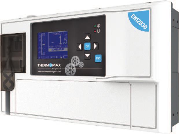
3 Presentation COMMS. AREA BACK BOX FRONT COVER FRONT LID SUMMARY OF FEATURES Datalogger Temperature /humidity from each Channel can be set to sample every 1/5/15/30/60 minutes and stored to an internal databank Up to 12 channels of data logging can be employed using the module configuration Power Supply V AC Mains Contents of internal databank can be transferred to the USB Flash Memory and viewed or transferred to the PC via website Universal panel mount or wall mount box Expandable modular design IP54 Rated Battery Back-up up to 6hrs Backward compatible with old sensors (PT 100 terminated with RJ 11) EN12830 certified CE tested On Board Web Server (IP addressable) Large data storage capacity USB Firmware Upgrade Functionality Module Auto-Detect and self-configuration Door Alarm Configuration Function (4 doors per module) Alarm 2-Stage high and low level alarms with mute facility Stage 1 temperature threshold with trigger delay Stage 2 limit temperature with immediate trigger Alarm history record for low alarm, high alarm and power fail Battery back-up for power-fail operation Summary screen for Alarm Overview Note: The information supplied in this manual is for guidance only no part of this may be used for any agreement, whether express or implied, or to form any contract. TempControl 3
4 Installation Note: This installation procedure is for guidance only, and its suitability should be verified by the installer. SAFETY PRECAUTIONS The following safety precautions are strongly recommended: 1. Before attempting to install and operate the unit, read the instruction and installation manual carefully. 2. Installation and any maintenance should only be carried out by suitably qualified personnel. 3. It is recommended that the unit be connected to the mains supply via a suitably rated isolating switch. 4. WARNING: When the unit is connected to the mains supply and the cover is open, the circuits at mains voltage will be exposed. Therefore when installing the unit, ensure all required connections (including battery connected, if included), are made and covers replaced before turning on the mains supply. Ensure that all the connections made are secure. If any maintenance work e.g. installing a new battery, is required ensure that the unit is isolated from the mains supply before removing the cover. Never leave the unit unattended if the cover has been removed and the mains supply is connected. 5. Do not exceed unit ratings as shown on the ratings label. 6. It is advisable to route mains cables away from low voltage or sensor cables. (i) THX Unit Note: For viewing comfort, the unit should be positioned at eye level. The ambient temperature of the unit is (0 C to +40 C). It is always good practice to keep electronic equipment away from cold, heat and electrical plant, as extremes of temperature may reduce the lifetime of the device, and heavy electrical loads, switches, relays or contactors too close to the device may cause electrical and electro-magnetic interference when switched on or off. (ii) Sensors The THX may be used with a variety of sensors of different cable lengths. If required, sensors are available with extended cable lengths or alternatively, sensor extenders are available also in a variety of lengths. If the sensors need to be extended, but factory-made extenders are not available, they can be extended using a suitable 3 or 4 core cable, according to the diagram shown below WHITE RED BLUE GREEN GROUND SENSE COMPENSATE Please note however, that as with all PT100 sensor applications, a good connection is vital. It is therefore recommended that wherever there is any doubt, a factory extended sensor or sensor extender should be used. (iii) Alarm Relay Note: The alarm relays are 2 contact arrangements which are isolated (volt-free). These relays may be used to trigger an external bell, warning lamp or digital communicator (telephone dialler). Max rating of Alarm relays is 240 VAC. The alarm relay is software configurable to accommodate normally open or normally closed operation, as described below. Normally Closed Operation This is the default mode. Normally Open Operation In this mode, the relay outputs will break contact (open circuit) in the event of an alarm and make contact (closed circuit) in the event of power failure. If the external device is used, connect the alarm as appropriate, according to the diagram opposite. 4 TempControl


5 Installation (iv) Power Connections and Wiring Diagram Note: This device should be properly earthed. Flexible wires simplify connection to the terminals. All connections should be secure and adequately tightened. It is good practice to keep mains cables away from sensor cables and other low voltage signal cables. Connect the supply to the unit, as per diagram below, using the appropriate input voltage according to the application. (v) Battery The battery supplied is a 3.7V Lithium-polymer rechargeable battery and is plugged in but switched OFF. This should be switched ON after installation. See picture below. This battery is not essential for the system operation, but is used in the case of power failure, thereby continuing to log the 12 sensor inputs for approximately 6 hours. The system parameters will remain intact, in the event of a power failure, however all interface options (Ethernet, screen, keypad options, USB etc. will not function as normal) It is recommended that the battery is changed every 24 months, in order to maintain good power failure backup operation. When replacing, ensure that the type of rechargeable battery used is as specified. (3.7V Lithium-polymer rechargeable battery) TempControl 5
 6.")
6 Installation WALL MOUNT 1. Drill four holes in the wall, according to the template and insert the wall plugs 2. Remove the Front Lid by unscrewing two screws 3. Disconnect the modules 4. Separate the front cover by unscrewing two screws 5. Remove the required knock outs from Back Box for the cables to pass through (always separate front cover before removing the knock outs) 6. Insert the cable glands 7. Screw in the Back Box to the wall 8. Pass the cables through the glands 9. Mount the Front Cover on the Back Box 10. Insert the modules 11. Connect the power supply cable and sensors 12. Tighten the cable glands 13. Mount the front lid PANEL MOUNT (required panel mount kit) 1. Cut a hole in the panel with the described dimensions, (see page 7) 2. Remove the Front Lid unscrewing two screws 3. Disconnect the modules 4. Separate the front cover by unscrewing two screws 5. Remove the required knock outs from Back Box for the cables to pass through (always separate front cover before removing the knock outs). Ethernet cable can be passed through the hole which is under the label on the front cover (see picture below) 6. Attach the Panel Mount Seal, ensure that it is on the right position 7. Insert the Back Box into the panel cut out 8. Attach the four Panel Mount Fixing Clips (supplied), to the four studs at either side of the unit, (see page 7). 9. Tighten the four Panel Mount Fixing Screws 10. Insert the cable glands 11. Pass the cables through the glands 12. Mount the Front Cover on the Back Box 13. Insert the modules 14. Connect the power supply cable and sensors 15. Tighten the cable glands 16. Mount the front lid 6 TempControl

7 Installation 296mm 169mm Area required to be cut out for panel mount 50mm 50mm Panel mount fixing clip Panel mount fixing screw Panel mount fixing screw Panel mount fixing clip 177mm 168mm 168mm 177mm Right side view Left side view Panel mount fixing clip Panel mount fixing screw Panel mount fixing screw Panel mount fixing clip TempControl 7


8 THX-DL Operation In order to fully understand the operation of the unit, this section should be read carefully. (i) Graphic LCD Display Displays all the information. The contrast is adjustable to suit the user. (Refer to section 6.2) (ii) Function Keys The six keys are used to navigate through the unit s menus, allowing for easy access to the THX many options and settings. ESC The four arrow keys select an option in the displayed menu, the key select the menu and the key returns to the previous menu. A menu I.D. is displayed at the top of each screen to indicate to the user which particular menu is being addressed. (iii) Indicators 1.0 SUMMARY SCREENS These screens allow the user to view all the data logged by the unit for each channel, e.g. Sensor Summary, Door Summary, Alarm Summary, and Daily Max/Min Temperatures. 1.1 Sensor Summary From the Main Menu screen, press key twice to reveal the Sensor Summary Screen. This screen displays the current temperature/humidity readings of each of the connected channels and indicates if that channel is in alarm or not. The ESC key will return the user to the previous menu option. 8 TempControl
 1.")

9 THX-DL Operation 1.2 Door Summary key, followed by the key to select Door Summary in the menu. Confirm selection using the key to reveal the Door Summary Screen. This screen displays the status of each of the 12 digitals inputs, indicating whether it is OPEN, CLOSED or OFF. (Default status is OFF) 1.3 Alarm Summary key, followed by the key to select Alarm Summary in the menu. Confirm selection using the key to reveal the Alarm Summary Screen. These screens display the High and Low Alarm Limit settings for each channel and also display the current temperature/humidity readings. The sensor s status is also displayed, i.e., in alarm or ok. alarm limit or alarm threshold has been reached no alarms Pressing the key will reveal information for channels 5 to 8, and pressing once more, reveals information for channels 9 to 12. TempControl 9

10 THX-DL Operation 1.4 Daily Max/Min Readings key, followed by the key to select Daily Max/Min in the menu. Confirm selection using the key to reveal the Daily Max/Min Screen. This function enables the user to view the minimum and maximum Temperatures that have been recorded on each channel over the past 24 hours. alarm limit or alarm threshold has been reached no alarms 2.0 CHANNEL VIEW key to select Channel View from the main menu. Confirm using the key to reveal the Channel View screen. The user can view any of the channels from 1 to 12 using the and keys. The clock is displayed in 24-hour format. The temperature bar graph displays the current temperature of the selected channel. The high and low alarm limits are shown as shaded areas. Any channel can be set up to read either temperature or humidity by choosing the sensor type, as per Section 4.4 of this manual. TEMPERATURE or REL HUMIDITY will be displayed as per above illustration and the values will be displayed as either C or % rh (relative humidity). The current temperature/humidity for the selected channel is displayed digitally along with the daily maximum and minimum temperature, which are reset at midnight. 10 TempControl

11 THX-DL Operation 3.0 ALARM SETTINGS key to select Alarms Settings from the main menu. Confirm selection using the key to reveal the Alarms Selection screen. From this screen, the user can select to view the alarm information on any of the channels from 1 to 12, using the and keys and pressing the key to confirm. Bar Graph Scale By pressing the or key, the bar graph display scale may be adjusted to show temperature/humidity range best suited to the particular installation. High Alarm Stage 1 Temperature (-99 C to +150 C)/Humidity (0%rH to 100%rH) The Stage 1 Alarm is a time/temperature related alarm. If the maximum threshold is exceeded, a timer is initiated, and no further action is taken at this time. High Alarm Stage Delay (1-99 min.) After the maximum threshold has been exceeded, the alarm will not be triggered until the timer exceeds the time delay set here. If the temperature drops below the threshold before the expiry of this delay, the timer is reset. If following this, the temperature rises above the threshold again, the timer restarts from zero. High Alarm Limit Stage 2 temperature (-99 C to +150 C/Humidity (0%rH to 100%rH) If at any time this limit is exceeded, the time delays will be overridden and the alarm will trigger immediately. Low Alarm All the functions described for the high alarm also apply to the low alarm. TempControl 11

12 THX-DL Operation 4.0 SETTINGS 4.1 Set Clock key to select Settings from the main menu. Confirm selection using the key to reveal the Settings Menu. Select Set Clock from the menu and press the key to confirm. The Set Clock screen allows the user to change the time and date settings of the unit. The highlighted parameter is adjusted by pressing the or key. The parameters are Year, Month, Day, Hour and Minutes. To change any of these, press the or key. Press the key to confirm the changes and back to the previous screen. 4.2 Alarm Mute Setup key to select Settings from the main menu. Confirm selection using the key to reveal the Settings Menu. Select Alarm Mute Setup from the menu and press the key to confirm. The Alarm Mute Period for all channels ranges from 0 to 95 minutes. If any key is pressed during an alarm situation for a channel, the buzzer will be muted for this period. The default alarm mute period is 5 minutes. In order to change the alarm mute period for any channel, move to the required channel by using the or key to increase the alarm mute period, press the key. To decrease, press key. If a channel is switched off, the alarm parameters will automatically revert back to the default factory settings to prevent an alarm occurrence. These parameters cannot be changed until the sensor input is switched on again. 12 TempControl


13 THX-DL Operation 4.3 Channel On/Off key to select Settings from the main menu. Confirm selection using the key to reveal the Settings Menu. Select Channel On/Off from the menu and press the key to confirm. Each sensor channel can be switched on or off. By default, all channels are on. If a new module in inserted the default mode for the new channels will be on. When the sensor input is switched on, the actual reading will be monitored every 15 minutes (default sample period). If the sensor input is switched off, the unit will display OFF. To switch channel off, press the key. To switch the channel back on, press the key. 4.4 Sensor Type key to select Settings from the main menu. Confirm selection using the key to reveal the Settings Menu. Select Sensor Type from the menu and press the key to confirm. The 12 sensors inputs can be configured to read either Temperature or Relative Humidity. As a factory default, all 12 sensor inputs are configured to accept temperature sensors. To change the sensor input configuration to Humidity, press the key. To change it back to Temperature, press the key. TempControl 13
14 THX-DL Operation 4.5 Door On/Off key to select Settings from the main menu. Confirm selection using the key to reveal the Settings Menu. Select Door On/Off from the menu and press the key to confirm. The status of 12 doors can be configured to be switched ON or OFF. As a factory default, all 12 doors are switched OFF. To switch a door off, press the key. To switch a door back on, press the key. 4.6 Door Setup key to select Settings from the main menu. Confirm selection using the key to reveal the Settings Menu. Scroll down using the key to the second page of the menu, select Door Setup from the menu and press key to confirm. The Door Setup is purely for display/graphing purposes only. It allows the user to associate any channel with any number of digital inputs, e.g., doors. The user can select any channel from screen 4.6 using and keys and pressing the key to confirm. To set which door inputs are associated with each channel use the and keys to select a door input and use the key to select and the key to deselect. Indicates that the digital input is associated with the selected channel. Indicates that the digital input is not associated with selected channel. Indicates that the status of the door is OFF. Note The user cannot set the door input association if a door is turned off (see 4.5) 14 TempControl


15 THX-DL Operation 4.7 Relay Setup key to select Settings from the main menu. Confirm selection using the key to reveal the Settings Menu. Scroll down using the key to the second page of the menu, select Relay Setup from the menu and press the key to confirm. This feature allows the user to associate any channel with a number of relay outputs, e.g., alarm relays. If channel 1 goes into fault mode, each alarm associated with channel 1 will be triggered. The user can select any channel from screen 4.7 using and keys and pressing the key to confirm. To set which channel is associated with each relay use the and keys to select a channel and use the key to select and the key to deselect. Note: Every channel can be configured to work with each relay. 4.8 Relay Normally Closed/Normally Open key to select Settings from the main menu. Confirm selection using the key to reveal the Settings Menu. Scroll down using the key to the second page of the menu, select Relay N/C N/O from the menu and press the key to confirm. The default state of each relay is set to normally closed (N/C). The user can change the setting of individual relays to be N/O or N/C. N/C Normally Closed Operation. This is the default mode. The relay outputs will make contact in the event of an alarm or power failure. N/O Normally Open Operation. In this mode, the relay outputs will break contact (open circuit) in the event of an alarm and make contact (closed circuit) in the event of power failure. To change the setting of each relay to normally closed, press the key. To change the setting back to normally open, press the key. TempControl 15


16 THX-DL Operation 4.9 Calibration key to select Settings from the main menu. Confirm selection using the key to reveal the Settings Menu. Scroll down using the key to the second page of the menu, select Calibration from the menu and press the key to confirm. To enter the Calibration Trimming screen, press and hold the key for 8 seconds. Calibration trimming allows qualified personnel to adjust the Sensor Measurement by ±3 C / ±3%rH. A known reference value should be used. Use the keys to move to the channel that requires calibration trimming. Then use the or key to adjust the current temperature reading to the reference value read at the input. 16 TempControl

17 THX-DL Operation 4.10 Network key to select Settings from the main menu. Confirm selection using the key to reveal the Settings Menu. Scroll down using the key to the second page of the menu, select Network from the menu and press the key to confirm. Please enter your network details or choose DHCP for Automatic Network Configuration. To set Automatic Network Configuration, use the key to select DHCP and use the key to select or deselect this option. Indicates that the DHCP is OFF. Indicates that the DHCP is ON. Select and use the key to save the settings. 5.0 PLOT 5.1 Current Day key to select Plot from the main menu. Confirm selection using the key to reveal the Plot Menu. Select Current Day from the menu and press the key to confirm. This screen displays the plot of the temperature / humidity readings logged for the current day. The user can select any channel from screen 5.1, using the and keys and pressing the key to confirm. The user can read sample information using the and keys. TempControl 17


18 THX-DL Operation 5.2 History key to select Plot from the main menu. Confirm selection using the key to reveal the Plot Menu. Select History from the menu and press the key to confirm. 1 Select the channel to be displayed using the and keys and press the key to confirm. 2 Select the year, month and day using the and keys and press the key to confirm. History functions that are available from this screen are as follows: By pressing the key, the values of the previous day will be displayed. By pressing the key, the unit will increment through the values, according to the sample period. At the end of each day, the next day logged in the databank will be displayed. By pressing the key, several new options become available to the user, these are detailed below. Return to the Main Menu, by selecting MAIN MENU from the pop-up menu and pressing the key Go to the select day screen, by selecting SELECT DAY from the pop-up menu and pressing the key. Use the keys to select the date and press the key to confirm. Display the door information by selecting SHOW DOOR from the pop-up menu and pressing the key to confirm. View the information of any door by using the keys. 18 TempControl


19 THX-DL Operation 6.0 SERVICE 6.1 Test key to scroll down to the second page of the menu. Select Service from the main menu. Confirm selection using the key to reveal the Service menu. Press the key when the TEST menu is selected, the THX internal audible alarm will sound and all LED indicators will illuminate. 6.2 Contrast key to scroll down to the second page of the menu. Select Service from the main menu. Confirm selection using the key to reveal the Service menu. Select Contrast from the menu and press the key to confirm. Use the keys to adjust the contrast. 6.3 Keypad key to scroll down to the second page of the menu. Select Service from the main menu. Confirm selection using the key to reveal the Service menu. Select Keypad from the menu and press the key to confirm. To lock, press the key. To unlock, press the key. When the keypad is locked, the THX enters into a security mode, which renders the unit tamper-proof. TempControl 19


20 THX-DL Operation 6.4 Relay key to scroll down to the second page of the menu. Select Service from the main menu. Confirm selection using the key to reveal the Service menu. Select Relay from the menu and press the key to confirm. This screen displays the current status of the three alarm relays. The menu allows the user to test the functionality of the relay manually. The default mode is auto. To change the relay status, select AUTO and press the key to switch off the AUTO mode, press the key, then use the key to switch the relay ON or OFF. Indicates that the relay is on AUTO mode Indicates that the relay is on Manual mode Indicates that the relay is ON Indicates that the relay is OFF 7.0 LANGUAGE SELECT key to scroll down to the second page of the menu. Select Language Select from the main menu. Confirm selection using the key. The language used by the THX to communicate the information may be selected here, i.e., English, German or French. Use the or key to select the required language and then confirm the selection using the key. indicates the language that is currently selected. Press the ESC key to exit. 20 TempControl


21 THX-DL Operation 8.0 SAMPLE PERIOD key to scroll down to the second page of the menu. Select Sample Period from the main menu. Confirm selection using the key. Choose channel and press the key. Use the or key to select the required sample period and then confirm the selection using the key. indicates the sample period that is currently selected. Press the ESC key to exit. 9.0 UNIT INFORMATION key to scroll down to the second page of the menu. Select Unit Information from the main menu. Confirm selection using the key. This screen displays information about the unit, including the name, identification number (electronic serial number), MAC address, software version number and module information. TempControl 21
22 THX-DL Operation 10.0 DIAGNOSTICS 10.1 Databank key to scroll down to the second page of the menu. Select Sample Period from the main menu. Confirm selection using the key to reveal the Diagnostics Menu. Select Databank from the menu and press the key to confirm. Select the channel using the and keys and press the key to confirm. The DAYS USED window shows the used capacity of the internal databank. The DAYS FREE window shows the number of days which have not yet been used. The PERC FREE window shows the percentage of the databank which has not been used. The LAST ALRM window shows the last date on which an alarm condition occurred. The TRANSF ON window shows the date on which the contents of internal databank need to be transferred. The MAINS FL window shows the last date on which the power failed. During a power fail situation, this window will display the duration in minutes of the power failure 10.2 Channel key to scroll down to the second page of the menu. Select Sample Period from the main menu. Confirm selection using the key to reveal the Diagnostics Menu. Select Channel from the menu and press the key to confirm. Select the channel using the and keys and press the key to confirm. The CHANNEL window shows the number of the currently selected channel. The MODULE window shows the number of the currently selected module. The INPUT TYPE window shows which type of sensor is being used. The CALIB DATA window shows calibration values, for factory use only. The LAST CALIB window shows the date when the THX was calibrated. The ALARM HI window shows the date when the last high alarm condition occurred for this channel. The ALARM LO window shows the date when the last alarm condition occurred for this channel. 22 TempControl


23 USB THX data logger can transfer data to/from a USB memory stick. The user can download the logged data and the unit settings to any USB memory device in FAT 32 format. The USB memory key can also be used to load new unit settings; this is useful, for example, for importing the settings from a previously configured unit. To enter to the USB menu, connect the USB stick to USB port when the Sensor Summary Screen is displayed. 1. Download Data From the USB Menu screen, press key to reveal the Download Data Screen. Use the or key to select the required channel and then confirm the selection using the key. Choose the sample period from the pop-up menu using the or key and then confirm the selection using the key. Choose another channel or select and confirm using the key. The download bar will appear indicate the downloading progress. Do not remove the memory stick until the progress bar disappears. The data is saved to a file in.csv format, compatible with Microsoft Excel. The file name is automatically generated by the Data Logger. TempControl 23


24 USB 2. Download Setup key, followed by the key to select Download Setup in the menu and then confirm selection using the key to start download the settings. Do not remove the memory stick until the progress bar disappears. The data is saved to a file in setup.txt format. 3. Upload Setup key, followed by the key to select Upload Setup in the menu and then confirm selection using the key to start upload previously downloaded settings from the memory stick. Do not remove the memory stick until the progress bar disappears. 4. Service For use only by authorised personnel and trained installers. 24 TempControl
 using Ethernet CAT-5 cable or directly to the network adapter on your computer and open a web browser - Windows Internet Explorer (version 8.0 or higher) or Firefox.")
25 Web Server To connect with unit s embedded Web Server, connect unit to the network (switch, hub, router etc.) using Ethernet CAT-5 cable or directly to the network adapter on your computer and open a web browser - Windows Internet Explorer (version 8.0 or higher) or Firefox. Input the unit s IP address (default ), see section Network connection Direct connection Enter the username and password (as provided below). Default username and password: User: user Password: password TempControl 25


26 Web Server 1. Live Data Live data screen displays the current temperature/humidity readings of each of the connected channels and indicates if that channel is in alarm or not. The status of each of the 12 digitals inputs is also displayed, indicating whether it is OPEN, CLOSED or OFF. To change the language, click on the suitable flag as outlined below. 2. Status This screen displays the current Firmware, ID and battery status. The memory status of each channel is represented in Days used and Days free. Users can erase data from each channel by pressing and confirm. button and confirm or erase all data by pressing 26 TempControl

27 Web Server 3. Setup Setup screen display settings for each channel and allows user to edit them. Choose the channel for which you want to change the settings and edit them: switch channel ON or OFF choose the sensor type choose the sample period set the High Alarm thresholds set the Low Alarm thresholds associate door with chosen channel associate Alarm relay with chosen channel To save the changes click the button. TempControl 27


28 Web Server 4. User User screen allow user to change the username and password and to restore factory settings. To change the password enter old username and password, then enter new username and password, confirm password and click the button. To restore factory setting click the button and confirm. 5. Time Time screen allows user to change the unit time. To change the date and time use the, and click on the button to save the changes. 28 TempControl


29 Web Server 6. Graph Graph screen allow user to generate multiple channel graph. To generate the graph, set the date, choose the channels and click on the button. User can set the graph scale using buttons. 7. Network Network screen display network setting for the unit and allow user to change them. Please enter your network details or choose DHCP for Automatic Network Configuration. To set Automatic Network Configuration, click on the and click the button to save. Indicates that the DHCP is OFF. Indicates that the DHCP is ON. TempControl 29
30 Specification ELECTRICAL Supply Voltage: Fuses: Relay Output: Ambient Temperature: V AC Single Phase 1A 20mm Slow Blow Glass Fuse Alarm: 5A changeover 2 pin isolated (volt free contacts) 0 C to +40 C MECHANICAL: Dimensions: width: 300mm height: 100mm depth: 180mm weight: 1.4kg sensor: (each) 0.13kg Box Material: Display: Plastic Large LCD with backlight SENSORS: Type: Compensation: Cable Length: Battery: SX PT 100 Platinum Film 3 wire compensated A variety of lengths are available from 5m to 50m 3.7V Lithium polymer 1000mAh ACCESSORIES: 4 Channel Module Sensor (5m Cable) Sensor (15m Cable) Sensor (25m Cable) Sensor Extender 10m Sensor Extender 20m Sensor Extender 50m Humidity Sensor Wall Bracket for Humidity Sensor 30 TempControl
31 WALL MOUNT TEMPLATE 31
32 Kingspan Environmental 180 Gilford Road, Portadown, Co. Armagh, Northern Ireland BT63 5LF Sales Support Office: +44 (0) Part of In keeping with Company policy of continuing research and development and in order to offer our clients the most advanced products, Kingspan Environmental reserves the right to alter specifications and drawings without prior notice. Issue No. 1: April 2012
THX-DL Data Logger USER & INSTALLATION MANUAL V Refrigeration
 THX-DL Data Logger USER & INSTALLATION MANUAL V3.2016 www.thermomax-refrigeration.com Refrigeration Contents Presentation PRESENTATION Summary of Features 2 COMMS. AREA INSTALLATION 6.0 Service Screen
THERMOMAX SMX 100. Microprocessor Based Refrigeration Controller Datalogger and Alarm ENGLISH.
 THERMOMAX SMX 100 Microprocessor Based Refrigeration Controller Datalogger and Alarm ENGLISH www.thermomax-group.com CONTENTS SECTION 1 - INTRODUCTION...... 2 SECTION 2 - INSTALLATION....... 3 2.1 - SMX
THERMOMAX COLTREC RCX 100 MICROPROCESSOR REFRIGERATION CONTROL SYSTEM ENGLISH.
 THERMOMAX COLTREC RCX 100 MICROPROCESSOR REFRIGERATION CONTROL SYSTEM ENGLISH www.thermomax-group.com CONTENTS SECTION 1 - INTRODUCTION... 2 SECTION 2 - INSTALLATION... 3 2.1 - RCX 100 UNIT... 4 2.2 -
Introduction. OM-THA2
 Introduction. The OM-THA2 is a multi-function product that monitors Temperature, Humidity and Dew Point, provides alarms for out of range conditions, and continuously logs data. It consists of a base unit
Product Data Sheet. Remote Terminals. Features:
 Remote Terminals Product Data Sheet Features: Based around two core products, the Mx- 4010 Remote Display Terminal (RDT) and the fully functional Mx-4020 Remote Control Terminal (RCT). Both remote terminals
PWM. Solar Charge controller with Ethernet. Solar Smart PWM 20Amp. Hardware Description : Release : 19 June 2014
 Solar Charge controller with Ethernet Release : 19 June 2014 Hardware Version : Version 1 Firmware version 1 PC Application Software : Version 1.0.0.0 Hardware Description : The Solar Smart regulator was
THA2 TEMPERATURE/ HUMIDITY/ DEWPOINT ALARM WITH LOGGING CAPABILITY. 99 Washington Street Melrose, MA Phone Toll Free
 99 Washington Street Melrose, MA 02176 Phone 781-665-1400 Toll Free 1-800-517-8431 Visit us at www.testequipmentdepot.com THA2 TEMPERATURE/ HUMIDITY/ DEWPOINT ALARM WITH LOGGING CAPABILITY Introduction.
Added password for IP setup page : Password must be in IP format!
 NETWORK POWER MONITOR Release : 21 August 2014 Hardware Version : Version 7 Firmware version 1.00 PC Application Software : Version (latest)...2 Added password for IP setup page : Password must be in IP
OPERATING INSTRUCTIONS. G214 Software - Version 4
 OPERATING INSTRUCTIONS G214 Software - Version 4 Control Panel (G-214 Controller) 1 2 3 4 5 6 7 8 19 9 10 11 12 13 14 15 16 17 18 Control Panel Description 1. Probe shown in Main screen 2. Probe temperature
SmarTemp Control fx 2.0
 Digital Timer Interface Installation / Operation Instructions General Thank you for choosing Webasto to meet your heating needs. The Webasto SmarTemp Control fx 2.0 enables you to preset start-up cycles
Operating & Maintenance Manual. Alert-4 Ethernet LCD Master Alarm
 Operating & Maintenance Manual Alert-4 Ethernet LCD Master Alarm w w w. a m i c o. c o m Contents User Responsibility 4 Introduction 4 Features 5 Description of the Alarm 5 Shipment Details 5 The Alarm
QA16 Addressable System
 QA16 Addressable System Operating Manual HORING LIH INDUSTRIAL CO., LTD. www.horinglih.com QA16 System Characteristics Each loop can connect with 250 devices. Easy system programming through PC to panel.
ECOLOG TN2, TN3-P, TN4, TN4-L, TP2, TP4-L,TH1, TH2
 TN2, TN3-P, TN4, TN4-L, TP2, TP4-L,TH1, TH2 1. Product Overview 1.1 Display Large LCD display for measured values and status Time Alarm (will stay lit until Upper / Lower limit value (except for TN2) the
E N G L I S H FIRE ALARM ASPIRATION SENSING TECHNOLOGY QUICK INSTALLATION GUIDE STAND-ALONE FAAST LT MODELS FL0111E FL0112E FL0122E. 367 mm.
 E N G L I S H FIRE ALARM ASPIRATION SENSING TECHNOLOGY QUICK INSTALLATION GUIDE STAND-ALONE FAAST LT MODELS FL0E FL0E FL0E mm mm 0 mm DESCRIPTION The LT FL0 Series is part of the Fire Alarm Aspiration
Model: Edge-HC. 1 edge-hc
 Model: Model: Edge-HC 1 edge-hc Table Of Contents Product Image Table of Contents Installation Procedure System Type LCD Display Power On/OFF Setting the Time & Date Mode Select Fan Speed Temperature Display
TV2 Room Pressure Monitor Quick Start Guide
 TV2 Room Pressure Monitor Quick Start Guide 1. The Care and Use guide for your TV2 Room Pressure Monitor can be downloaded here: www.e2di.com/usersguides.html Please print out the Users Guide. Although
ACTIVE INFRARED BARRIER
 Although PROTECH provides high security indoor intrusion sensors for the military and government markets, our specialty is outdoor protection. Since we first introduced our PIRAMID outdoor dual technology
EXPERT TRI-STAR. Temperature controller. User s Manual
 Temperature controller r s Manual WARNINGS The warranty can be void if this product is used in a manner not specified by the manufacturer. Every effort has been made to ensure that this manual is complete,
D-TECT 3 IP. GJD260 IP Motion Detector
 D-TECT 3 IP GJD260 IP Motion Detector PACKAGE CONTENTS 1 x D-TECT 3 IP 1 x Drilling template for fixing holes 3 x 31.75mm wall plugs 3 x 31.75mm screws 2 x Spare sliding curtains 2 x Tamper feet 1 x Tamper
NexSysLink. 2 CAN Display Operation Manual. CAN Instruments Product Family
 NexSysLink CAN Instruments Product Family 2 CAN Display Operation Manual Contact Beede Beede Electrical Instrument Company, Inc. 88 Village Street Penacook, NH 03303 (603) 753-6362 Toll-free 800-451-8255
Model: Available in : Sapphire Black and Glacier White. 1 Series
 Model: Available in : Sapphire Black and Glacier White 1 Series Table of Contents Product Image 1 Frost Protection 20 Table of Contents 2 Power ON/OFF 21 What is a Programmable Room Thermostat? Installation
Table of Contents. Product Image 1 Locking/Unlocking the neoair 24 Table of Contents 2 Frost Protection 25 What is a Programmable Room Thermostat?
 Table of Contents Product Image 1 Locking/Unlocking the neoair 24 Table of Contents 2 Frost Protection 25 What is a Programmable Room Thermostat? 3-4 Power ON/OFF 26 Holiday Programming 27 Installation
Model: 1 Series 12V. Available in: Sapphire Black and Glacier White
 Model: Available in: Sapphire Black and Glacier White 1 Series Table of Contents Product Image Table of Contents What is a Programmable Room Thermostat? Installation Procedure Mode Select Pairing the neohub
THERMO BUTTON HYGRO BUTTON The smallest temperature and humidity loggers in the world!
 THERMO BUTTON HYGRO BUTTON The smallest temperature and humidity loggers in the world! FOR ALL YOUR TEMPERATURE AND HUMIDITY CONTROLS, PRODUCT TRACKING, TRANSPORT, STORAGE CONTROLS, HACCP! Small, rugged,
i.c³ User Guide For Helmer i.series Ultra-Low Freezers A/A
 i.c³ User Guide For Helmer i.series Ultra-Low Freezers 360175-A/A Document History Revision Date CO Supersession Revision Description A 18 APR 2014* 9275 n/a Initial release. * Date submitted or change
Operations Manual TS400. Test Station for G450/G460 Gas Detector
 TS400 Test Station for G450/G460 Gas Detector Operations Manual 1194 Oak Valley Dr, Ste 20, Ann Arbor MI 48108 USA (800) 959-0329 (734) 769-0573 www.goodforgas.com GfG Products for Increased Safety Congratulations
D-TECT 2 IP. GJD230 IP Motion Detector
 D-TECT 2 IP GJD230 IP Motion Detector PACKAGE CONTENTS 1 x D-TECT 2 IP 1 x Drilling template for fixing holes 3 x 31.75mm wall plugs 3 x 31.75mm screws 2 x Spare sliding curtains 2 x Tamper feet 1 x Tamper
AS200 Wireless Alarm, Monitoring and Data Logging System USERS MANUAL
 ALARMING MITORING DATA LOGGING AS200 Wireless Alarm, Monitoring and Data Logging System USERS MANUAL Features Multi Function Alarm / Data Transmitter Multi Channel Receiver Range Increase Transceiver Internet
3D_ISS. Integrated Software System. User Guide Manual
 3D Digital Design & Development LTD 58/60 Edward Road Tribec House New Barnet EN4 8AZ 020 8440 7060 3D_ISS Integrated Software System User Guide Manual Copyright 2014 3D Digital Design and Development
Smart thermostat with Humidification/De-humidification control
 x Smart thermostat with Humidification/De-humidification control Enter/Confirm Scroll Right = Increase Left = Decrease Back/Cancel TABLE OF CONTENTS Everyday Use 1. Adjusting Temperature...3 2. Adjusting
Model: Available in: Sapphire Black and Glacier White. 1 Series
 Model: Available in: Sapphire Black and Glacier White 1 Series Table of Contents Product Image Table of Contents What is a Programmable Room Thermostat? Installation Procedure Mode Select Pairing the neohub
Digital Marine Exhaust Temperature Alarm
 Digital Marine Exhaust Temperature Alarm Model: SM007D/S INTRODUCTION COMPONENTS Marine water cooled exhaust systems are designed to withstand temperatures of up to about 120 C. However the exhaust gases
BURGLAR ALARM PANEL BS-468
 BURGLAR ALARM PANEL BS-468 Contents 1. Description... 3 2. Instructions for the user... 4 2.1Basic operations... 4 Complete system.... 4 Split system.... 4 2.2 Armed system indication... 5 2.3 Advanced
Alarm module for leak detection with webserver
 This instruction document consists of 2 parts : one part about the assembly of the components and one part about configuration and starting-up of the system. The assembly is done by the qualified installer
AGC 200 Advanced Gen-set Controller OPERATOR S MANUAL
 Advanced Gen-set Controller OPERATOR S MANUAL Display readings Push-button functions Alarm handling Log list Document no.: 4189340607A SW version 3.5X.X or later Table of contents 1. ABOUT THIS DOCUMENT...3
Operation Manual Fighter ProVision Software. Version: 0.0 Revision: 1
 Operation Manual Fighter ProVision Software Version: 0.0 Revision: 1 TABLE OF CONTENTS 1. Introduction 5 2. Software Installation 5 3. PC Users 6 3.1 Introduction 6 3.2 Default Code 6 3.3 Edit PC User
USER MANUAL USB Multi-Function Datalogger Model RHT35
 USER MANUAL USB Multi-Function Datalogger Model RHT35 Additional User Manual Translations available at www.extech.com Introduction Thank you for selecting the Extech multi-function, easy-to-use, portable
Table of Contents. Product Image Table of Contents What is a Programmable Room Thermostat? Installation Procedure
 1 Model: 1 Table of Contents Product Image Table of Contents What is a Programmable Room Thermostat? Installation Procedure 1 2 3-4 5-6 Mode Select Pairing the ProTouch iq Hub Pairing the ProTouch iq What
Peak Partners Web-Programmable Thermostat Homeowner s Manual. Look inside for a complete guide to the setup and operation of your new thermostat.
 Peak Partners Web-Programmable Thermostat Homeowner s Manual Look inside for a complete guide to the setup and operation of your new thermostat. Table of Contents Step 1: Getting Started...4-6 A. Thermostat
UV - Monitor UVT 16. Use. Description
 UV - Monitor UVT 16 Use The UVT 16 Monitor is used to monitor signals from UV probes or sensors applied to sources of radiation, providing a control system for small items of UV equipment. Description
TV2 Clean Room Monitor
 TV2 Clean Room Monitor 1. The Care and Use guide for your TV2 Clean Room Monitor can be downloaded here: www.e2di.com/usersguides.html Please print out the Users Guide. Although you should use the Users
GG-2 2-CHANNEL GAS DETECTION CONTROL PANEL. Installation and Operation Manual
 GG-2 2-CHANNEL GAS DETECTION CONTROL PANEL Installation and Operation Manual 2 GG-2 Warning Use this product only in the manner described in this manual. If the equipment is used in a manner not specified
BC-4000 Bilge Monitor/Controller Installation Manual
 SMART SWITCH TECHNOLOGIES BC-4000 Bilge Monitor/Controller Installation Manual Table of Contents Introduction 1 System Overview 1 System Overview (cont.) 2 Wiring Block Diagram 3 System Layout 4 Wiring
USB Multi Function Dataloggers. RHT30 Humidity/Temperature Datalogger. TH30 Dual Temperature Datalogger
 USER MANUAL USB Multi Function Dataloggers RHT30 Humidity/Temperature Datalogger TH30 Dual Temperature Datalogger Additional User Manual Translations available at www.extech.com Introduction Thank you
Intelligent Security & Fire Ltd
 Product Data Sheet Mx-4000 Series User Manual MX-4100, MX-4200, MX-4400, Mx-4400/LE & Mx-4800 Fire Alarm Control Panels The operation and functions described in the manual are available from Software Versions
Advisor Advanced Mobile Application User Manual
 Advisor Advanced Mobile Application User Manual Content Warnings and Disclaimers 2 Advanced Mobile 2 Contact information 2 Description 2 Screen navigation 4 Gestures 4 Menu 4 Help navigation 4 Login 5
IMPORTANT. PLEASE NOTE: The infrared beam path MUST be kept clear of obstructions at all times!
 USER GUIDE English IMPORTANT PLEASE NOTE: The infrared beam path MUST be kept clear of obstructions at all times! Failure to comply may result in the Detector initiating a Fire or Fault signal. Contents
LMS-188-4P-BMS 4 POINT DIGITAL MONITOR/ALARM WITH PROTOCOL CONVERTER OPERATING INSTRUCTIONS
 G LMS 188 4P BMS August, 2018 LMS-188-4P-BMS 4 POINT DIGITAL MONITOR/ALARM WITH PROTOCOL CONVERTER OPERATING INSTRUCTIONS! WARNING: This product can expose you to chemicals including lead, which is known
LC1 & 2. Fire Alarm Panel 6\VWHPLQVWDOODWLRQRSHUDWLQJ PDLQWHQDQFH LQVWUXFWLRQV
 LC1 & 2 Fire Alarm Panel 6\VWHPLQVWDOODWLRQRSHUDWLQJ PDLQWHQDQFH LQVWUXFWLRQV ZIRCONLC1 One Zone Conventional Fire Panel ZIRCONLC2 Two Zone Conventional Fire Panel Compliant with EN54-2:1998 & EN54-4:1998
D3 Wireless temperature alarm & monitoring system family. tek-troniks
 D3 Wireless temperature alarm & monitoring system family tek-troniks D3 Wireless temperature alarm & monitoring system family No server or dedicated pc No ongoing cloud costs or licencing fees. Fully web
12V. Model: Available in : Sapphire Black and Glacier White. 2 Series
 Model: Available in : Sapphire Black and Glacier White 2 Series Table of Contents Product Image 1 Locking/Unlocking the neostat 19 Table of Contents 2 Frost Protection 20 What is a Programmable Room Thermostat?
UNC100 Integra Manual
 UNC100 Integra Manual New Generation Building Security July 30, 2014 V1.2 Copyright Notice Copyright 1995-2014 by All rights reserved Worldwide. Printed in Canada. This publication has been provided pursuant
Sensor Control Panel
 USER S MANUAL PU SENS 01 Sensor Control Panel V55-6EN-03(SENS).indd 1 18.08.2015 10:37:16 2 PU SENS 01 CONTENTS Safety Requirements 2 Main Technical Data 3 Control Panel Mounting 3 Control Panel Operation
Proliphix. NT10e & NT20e. Configuration Guide
 Proliphix NT10e & NT20e Configuration Guide Rev 2.5 Page i of iii TABLE OF CONTENTS INTRODUCTION...5 THERMOSTAT MANAGEMENT INTERFACE (TMI) AUTHENTICATION...5 QUICK SETUP...5 IP Addressability...5 Real
Operating Instructions Model: PRT-TS WiFi RF. 01/13 Version 1 Ref: PRT-TSWIFI RF
 Operating Instructions Model: PRT-TS WiFi RF 01/13 Version 1 Ref: PRT-TSWIFI RF Contents Page Setting up your WiFi Thermostat 2-6 Remote Connection Setup 6-8 Pairing with the Receiver 8-12 Display Symbols
GASGUARDIAN Channel Controller OPERATING & INSTALLATION MANUAL
 GASGUARDIAN 2 3 2-Channel Controller OPERATING & INSTALLATION MANUAL GasGuardian 2 3 Operating and Installation Manual Table of Contents General description.... 3 Installation. 3 Locating the GasGuardian-2..
PRT-TS WiFi PRT-TS WiFi
 Model: PRT-TS WiFi Model: PRT-TS WiFi 1 Model: PRT-TS WiFi Table Of Contents Product Image 1 Frost Protection 16 Table of Contents 2 Heating ON/OFF 16 What is a Programmable Room Thermostat? Installation
IT801 Thermostat. User s Manual. The complete guide to the set up and operation of your new smart Wi-Fi thermostat.
 IT801 Thermostat User s Manual The complete guide to the set up and operation of your new smart Wi-Fi thermostat. The smart Wi-Fi thermostat system learns your comfort preferences, then finds opportunities
PowerRouter application guideline
 PowerRouter application guideline Software installation tool - version 3.4 Before operating the PowerRouter, you may initialize the PowerRouter by using the PowerRouter software installation tool. The
E N G L I S H FIRE ALARM ASPIRATION SENSING TECHNOLOGY QUICK INSTALLATION GUIDE ADDRESSABLE FAAST LT MODELS MI-FL2011EI, MI-FL2012EI AND MI-FL2022EI
 E N G L I S H FIRE ASPIRATION SENSING TECHNOLOGY QUICK INSTALLATION GUIDE ADDRESSABLE FAAST LT MODELS MI-FL0EI, MI-FL0EI AND MI-FL0EI mm mm 0 mm DESCRIPTION The LT MI-FL0 Series is part of the Fire Alarm
Installation, Configuration and User Manual
 Model 8826 System Controller Model 8826 System Controller Installation, Configuration and User Manual READ AND SAVE THESE INSTRUCTIONS WELCOME Thank you for choosing the Aprilaire HVAC Automation System.
Ontech GSM 9040/50. Reference Manual English -1 -
 Ontech GSM 9040/50 Reference Manual English -1 - Content Welcome... 5 This manual... 5 Text styles... 5 Support... 5 Disclaimer... 5 Overview... 6 Accessories... 6 External temperature sensor 9901... 7
Patriot Systems Limited
 COPYRIGHT 1997 - The Patriot Systems Ltd. Patriot Alarm Monitoring Automation Package is licensed for use on one computer, by the original person, or company, or organization whose name is registered with
USER MANUAL. ITAG 4 / ITAG 4 Bio/ ITAG 4 TH DATA LOGGER. UM-ITAG REV.B 03/02/2016
 USER MANUAL EN ITAG 4 / ITAG 4 Bio/ ITAG 4 TH DATA LOGGER Updated@ 03/02/2016 CONTENTS Product Overview... 3 Logger... 3 LCD... 4 Technical Specifications... 5 TEMPCENTRE SOFTWARE... 6 How to download
AK-CS On Board Guide
 MAKING MODERN LIVING POSSIBLE AK-CS On Board Guide electronic controls & sensors About this guide The AK-CS On Board guide highlights the use of the RMT tool, allowing remote software management. Consult
Static Pressure Control
 The (model SPC-2) is a fully programmable controller that provides extensive flexibility for your curtain or awning control needs. The SPC-2 automatically controls the pressure in a room by operating a
ZSC100 Gas Detection and Alarm System Controller
 ZSC100 Gas Detection and Alarm System Controller User Guide 1- Introduction... 3 1.1- General description... 3 1.2- Cautions and warnings... 3 2- Control panel... 4 2.1 Control panel overview... 4 2.2
Trident User s Manual
 Labkotec Oy Myllyhaantie 6 33960 Pirkkala FINLAND Tel. +358 (0)29 006 260 18.05.2017 Fax +358 (0)29 006 1260 Internet: www.labkotec.fi 34 pages Trident Copyright 2017 Labkotec Oy 1/34 TABLE OF CONTENTS
EasyLog Data Logger Series
 EasyLog Data Logger Series Overview EasyLog model EL-USB series products are a line of low cost, compact, battery-operated data loggers with built-in memory and USB interface. Each product in the line
ThermoControl 0 C - 10 C - 20 C - 30 C
 ThermoControl Product and Quality Reliability Alarm Functions & Documentation Global Monitoring 0 C - 10 C - 20 C - 30 C Global monitoring: global temperature measurement and real-time monitoring using
Manual# User s Manual. 200E Series. DCU 210E/208E Diesel Engine Control Unit RP 210E Remote Panel
 Manual# 1006494 User s Manual 200E Series DCU 210E/208E Diesel Engine Control Unit RP 210E Remote Panel User's Manual Rev. 1.0 Marine Pro 200E Series ~~~ DCU 210E Diesel Engine Control Unit DCU 208E Diesel
Instruction Sheet THERMOCOUPLE DATA LOGGER WITH LCD DISPLAY AND USB INTERFACE
 Instruction Sheet OM-EL-USB-TC-LCD THERMOCOUPLE DATA LOGGER WITH LCD DISPLAY AND USB INTERFACE Thermocouple Data Logger with LCD ORDERING INFORMATION Standard Data Logger OM-EL-USB-TC-LCD (Data Logger,
Universal Monitoring System. Model IMEC8A. User Manual Version 1.10 Software version 2.3.1
 Unit 7/8, Heathrow Causeway Estate, Ariel Way, Hounslow Middlesex, TW4 6JW +44 (0) 208 6302270 www.cpcuk.co.uk Universal Monitoring System Model IMEC8A User Manual Version 1.10 Software version 2.3.1-1
DATAssure. Laboratory wireless alarm & monitoring system
 DATAssure Laboratory wireless alarm & monitoring system Wireless alarm & monitoring system A new monitoring generation The DATAssure wireless monitoring system is used across a broad range of market sectors
ViewMatrix. Software for Online Monitoring & Control of Matrix2000 Conventional Fire Alarm Panels. Version: 2.0 Revision: 0.1
 ViewMatrix Software for Online Monitoring & Control of Matrix2000 Conventional Fire Alarm Panels Version: 2.0 Revision: 0.1 CONTENTS 1. Introduction...3 2. Keyboard...5 2.1 POWER indication - Normal Operation...5
Tempered Water Logic Control OPERATION l TROUBLE SHOOTING
 Tempered Water Logic Control OPERATION l TROUBLE SHOOTING English For MPE Multiple Chiller Units Control Panel TEMPERED WATER SYSTEMS L-2199 Rev. 20080223 Revision: L-2199 20101104 *** IMPORTANT NOTICE
Instruction manual MTL process alarm equipment. October 2016 CSM 725B rev 2 MTL RTK 725B. Configuration Software Manual
 Instruction manual MTL process alarm equipment October 2016 CSM 725B rev 2 MTL RTK 725B Configuration Software Manual SECTION 1 - INTRODUCTION... 5 Basic Requirements... 5 SECTION 2 - SOFTWARE INSTALLATION...
Replaceable LED modules. Sleep or unattended mode. Auto-silence and auto-acknowledge
 Replaceable LED modules 11 Alarm Sequences as per ISA-18.1 standard Each channel/window fully field programmable RS232 or RS485 MODBUS-RTU communication Repeat relay for each window and multifunction relays
IRIS Touch Quick Installation & Maintenance Guide. Version 1.0
 IRIS Touch Quick Installation & Maintenance Guide Version 1.0 Page 2 of 16 IRIS Touch Quick Installation & Maintenance Guide Version 1.0 Contents 1. Introduction... 4 2. Product Features... 4 3. Package
MultiSite Manager. Setup Guide
 MultiSite Manager Setup Guide Contents 1. Introduction... 2 How MultiSite Manager works... 2 How MultiSite Manager is implemented... 2 2. MultiSite Manager requirements... 3 Operating System requirements...
Follett Performance Plus
 Follett Performance Plus touchscreen user guide The next level of control in undercounter refrigeration Controller Operation - Performance Plus touchscreen Use and care of the LCD Performance Plus touchscreen
User Guide UTI-IQCP. Control panel for setting and monitoring of UTI-INV internal temperature regulator. v EN
 User Guide UTI-IQCP Control panel for setting and monitoring of UTI-INV internal temperature regulator v. 1.06 EN 1. MAIN DISPLAY SCREEN The main display screen is divided into five basic monitoring windows
I/O logger box. User manual NO POWER & SIGNAL CABLES TOGETHER READ CAREFULLY IN THE TEXT!
 I/O logger box User manual NO POWER & SIGNAL CABLES TOGETHER READ CAREFULLY IN THE TEXT! H i g h E f f i c i e n c y S o l u t i o n s WARNING DISPOSAL CAREL bases the development of its products on decades
Syncro AS. Analogue Addressable Fire Control Panel. User Manual
 Syncro AS Analogue Addressable Fire Control Panel User Manual Man-1100 Issue 02 Nov. 2008 Index Section Page 1. Introduction...3 2. Safety...3 3. Panel Controls...4 3.1 Access Level 1...4 3.2 Access Level
ZX1e ZX2e ZX5e. Document No Issue 01 user manual
 ZX1e ZX2e ZX5e Document No. 996-130 Issue 01 user manual MORLEY-IAS ZX2E/ZX5E Fire Alarm Control Panels Table of Contents 1 INTRODUCTION... 4 1.1 NOTICE... 4 1.2 WARNINGS AND CAUTIONS... 4 1.3 NATIONAL
Ax60+ Multi-Gas. Service Manual
 Analox Limited 15 Ellerbeck Court, Stokesley Business Park, North Yorkshire, TS9 5PT, UK UK/RoW T: +44 (0)1642 711400 F: +44 (0)1642 713900 US T: (714) 891-4478 W: www.analox.net E: info@analox.net Copyright
PowerWizard. Level 1.0 & Level 2.0 Control Systems Training
 PowerWizard Level 1.0 & Level 2.0 Control Systems Training New Systems Current Systems Systems Comparison Level 1 Level 2 Level 3 Level 4 PowerWizard Level 3.0 PowerWizard Level 4.0 Overview Common parts
DI220 Using the Optional Docking Station The maintenance and operating functions of the Micro IV can be automated with the Micro IV Docking Station.
 DI220 Using the Optional Docking Station The maintenance and operating functions of the Micro IV can be automated with the Micro IV Docking Station. The following steps outline the correct sequence to
REPEATER FS5200R INSTRUCTION MANUAL
 REPEATER FS5200R INSTRUCTION MANUAL Instruction Manual Page1 CONTENTS 1. Introduction... 3 2. Function... 3 3. Technical data... 3 4. Contents of delivery... 4 5. General information... 5 6. Duty Mode...
Emerson Inspire 1HDEZ Installation Instructions. Thermostat/Interface Equipment Control TROUBLESHOOTING
 Emerson Inspire 1HDEZ-1521 Installation Instructions Thermostat/Interface Equipment Control TROUBLESHOOTING FAILURE TO READ AND FOLLOW ALL INSTRUCTIONS CAREFULLY BEFORE INSTALLING OR OPERATING THIS CONTROL
ComfortNet CTK04 Featuring the RedLINK Suite of Home Comfort Solutions
 ComfortNet CTK04 Featuring the RedLINK Suite of Home Comfort Solutions Agenda Comfort Advantage System Configurations Installing ComfortNet ComfortNet Control Set up Dehumidification and Defrost Settings
Table of Contents. i-vu CCN Standard 4.2
 i-vu CCN Standard 4.2 Owner's Guide CARRIER CORPORATION 2009 A member of the United Technologies Corporation family Stock symbol UTX Catalog No. 11-808-381-01 7/13/2009 Table of Contents Accessing your
Spa Touch Control Panel with BP2100, BP6013 spa controllers. (Spa Owner s Manual insert)
") Spa Touch Control Panel with BP2100, BP6013 spa controllers. (Spa Owner s Manual insert) P.N. 7876C (export) February 12, 2015 For Spas equipped with BP2100, BP6013 controllers and Spa Touch panel. Spa
Spa Touch Control Panel with BP2100, BP6013 spa controllers. (Spa Owner s Manual insert) P.N. 7876C (export) February 12, 2015 For Spas equipped with BP2100, BP6013 controllers and Spa Touch panel. Spa
Application Version: 2.0 and above Date Written: 03/09/2010. Copyrights , Global Security Devices, All Rights Reserved
 GSD WIN USER MANUAL Application Version: 2.0 and above Date Written: 03/09/2010 Copyrights - 2010-2012, Global Security Devices, All Rights Reserved TABLE OF CONTENTS TABLE OF CONTENTS...2 SETTING UP A
GasAlertMicroClip X3 Specifications
 GasAlertMicroClip X3 Specifications The instrument must satisfy the following: Physical Specifications Size (h x w x d) Physical size shall be no larger than 4.4 x 2.4 x 1.2 in. / 11.3 x 6.0 x 3.2 cm Weight
WiFi Hints & Tips. Contents. WiFi Hints and Tips 1. Page No. Section No. Title
 WiFi Hints & Tips Contents Page No. Section No. Title Section.0 System Set-Up 3 Section. Sensor Set-Up 4-5 Section. Sensor Set-Up (Configuring Network) 6-9 Section.3 Sensor Set-Up (Configuring Settings)
JUNO-NET. Fire Alarm Control Panel OPERATION & MAINTENANCE MANUAL
 Fire Alarm Control Panel & MANUAL CONTENTS SECTION -. Description of the fire control panel fascia.... Alarm.... Reset the system.... Sound and silence the alarms.... Read the Fire, Fault, Test and Disabled
EasyTronic III MANUAL SERVICE
 rev.6 EasyTronic III MANUAL SERVICE General characteristics: Power supply 24 Vac ±15% Max consumption at 24Vac 300mA Relay outputs 6 Maximum relay current 8 A res. Serial standard RS232 2 Serial standard
Intelligent Security & Fire Ltd
 full installation, commissioning and operating manuals can be downloaded from www.haes-systems.co.uk combined addressable / conventional fire alarm control panel User Guide Approved Document No. MFBU-04
Spa Touch Control Panel with 2000, 2100 controllers. (Spa Owner s Manual insert)
") Spa Touch Control Panel with 2000, 2100 controllers (Spa Owner s Manual insert) P.N. 7876B February 11, 2015 For Spas equipped with BP2000, BP2100 controllers and Spa Touch panel. Spa Touch Control Panel
Spa Touch Control Panel with 2000, 2100 controllers (Spa Owner s Manual insert) P.N. 7876B February 11, 2015 For Spas equipped with BP2000, BP2100 controllers and Spa Touch panel. Spa Touch Control Panel