easydetect and easydetect deluxe model train detector kits Quickar Electronics, Inc.
|
|
|
- Colin Fox
- 6 years ago
- Views:
Transcription
1 easydetect and easydetect deluxe model train detector kits Quickar Electronics, Inc. INSTRUCTIONS AND DIAGRAMS REVISED APRIL 17 TH 2012 Please note that the color of the calibration trimmer may be orange instead of the black pictured depending on what brand of trimmers are available Features, Set Up, Calibration, User Manual, and Assembly Instructions Thank you for purchasing our new detector circuit kit for model railroads. This kit can be used to provide a visual indication at your control panel of trains in hidden staging or it can also be used to turn on and off your crossing flashers at grade crossings Features: Least expensive train detector kit available Easy To Assemble even for someone who has never built an electronic kit Small Size so you can hide it virtually anywhere Easy to install on your layout only 2 small holes needed between the rails, so it is almost invisible Uses very little power requires a 6 to 12 volt dc power supply, and uses only milliamps

2 *******************************************************
3 Before we go any further let s discuss the various means of detecting a model train and their advantages versus disadvantages. 1. Current Detection. In a current detection scenario, your layout is divided into electrical blocks. When a locomotive enters that block it draws current that can be detected. This is how real railroads detect trains. Unfortunately to do this on a model railroad, more than just the first locomotive needs to draw current. This means you have to equip all or most of your cars with resistors or resistive paint between the wheels. For this reason we did not use current detection, because you would have to spend a bunch of money and time to modify all of your cars. 2. Optical Detection. This is the method our detector uses, in a very simple, inexpensive way. Our circuit uses 2 phototransistors ( or 4 phototransistors in our Deluxe Kit) to detect the ambient light on your layout. When something a loco or car covers at least one of the phototransistors, the detector circuit is activated. This is like an electronic switch that is turned on or off depending on whether it senses light or darkness. You can use our easydetect circuit to turn on a led at your control panel so you know where on your layout a train is located.useful in hidden staging yards, or to turn on and off a crossing flasher kit like the one we sell. The disadvantage to our circuit is that there must be enough light on your layout (there is a calibration adjustment you can make to adjust for most lighting levels, more on this later.) and if you are using it to turn on/off a crossing flasher, your train must be long enough that the 1st phototransistor will still be covered buy a car as your locomotive goes over the 2 nd phototransistor. Of course there are other optical detectors that either use ambient light, or infrared emitter/detectors, but they are a lot more expensive.in some cases 3 times as much! ASSEMBLING YOUR DETECTOR KIT You will need the following tools and supplies to assemble and install your detector kit:..small pencil size soldering iron with fine tip...rosin core solder..some small diameter (24-30 gauge) wire to connect the phototransistors to the circuit board, wire to connect to your 6 12 volt DC power supply, and wires
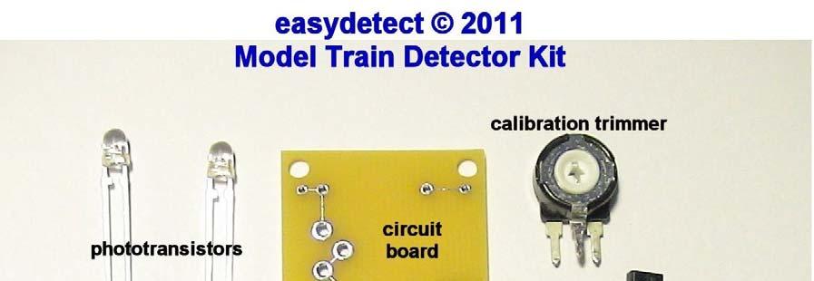
4 to connect to your load. Your load can be our crossing flasher kit, or an led mounted on your control panel..heat shrink tubing or electrical tape to insulate the leads of the phototransistors drill to make holes between the rails of your model railroad track for the 2 phototransistors Please look at the picture below to identify the parts, and where the parts go on the circuit board note that the phototransistors look just like 3mm leds


5 1. make sure the board is laying face up so that the silver lines between the holes are laying face up as shown start by placing the 2n3904 transistor thru the 3 holes in the circuit board and solder in place.please note the transistor has a rounded side and a flat side, so make sure you install the transistor the right direction as it appears in the pictures flat side facing out clip off the excess length of the transistor leads on the bottom of the board after soldering

6 3. place the board resistor ( 1k Ohm brown black red gold) as shown and solder in place note it does not matter which end of the resistor goes where clip off the excess length of the resistor leads on the bottom of the board after soldering

7 4. place the calibration trimmer in the holes as shown and solder in place
8 5. place color coded wires in the holes to run to the phototransistors
9
10 6. determine how far apart you want to place the phototransistors, and trim the wires to length 7. either slip some heat shrink tubing over the ends of the wire before soldering the wires to the phototransistors, or use electrical tape to insulate the legs of the phototransistors make sure that the long leg of each phototransistor is soldered to the correct color coded wire that then goes to the correct hole on the circuit board 8. Drill holes between the rails where you want your phototransistors to detect the train and insert the phototransistors in the holes so the rounded tops are facing upwards 9. solder color coded wires in the holes as shown for power to the kit and power to control your load follow the pictures and don t get them mixed up as connecting the kit backwards could destroy the kit

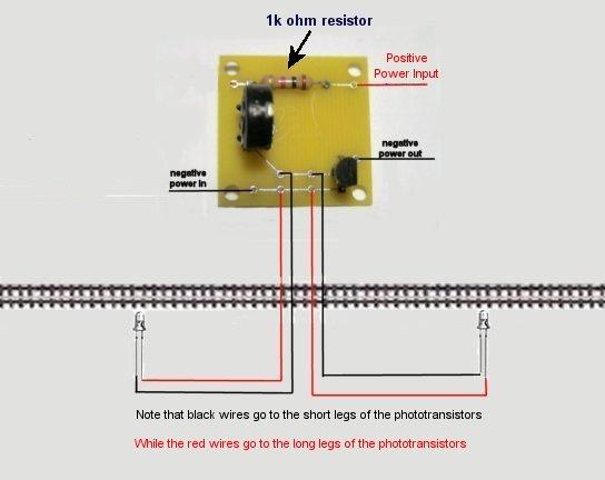
11 Calibration, Testing, and Connecting to other Circuits We supply the kit with a red led for testing and calibration purposes if all you need is to know where your train is at, you can mount this led at your control panel by using some long wires Below is the Wiring Diagram for connecting your Red Status Indicator Led that is supplied with the kit

12 Apply 6-12 volts DC power to the power input wires on the kit as per the picture above If the lights are fairly bright in your layout room the red led should light up when you cover either one of the two phototransistors with your finger. If the red led does not light when you cover either one or both of the phototransistors, then while keeping at least one of the phototransistors covered, take a small screwdriver, and turn the calibration trimmer until the red led turns on start by turning the calibration trimmer a small ways to the right then cover either one or both of the phototransistors, again by turning to either the left or right you should find a spot where the status led turns on when you cover one of the phototransistors. if you still cant get it to work, try increasing the light in you layout room maybe try a small clamp on lamp over one of the phototransistors and try adjusting the calibration trimmer again it should work.
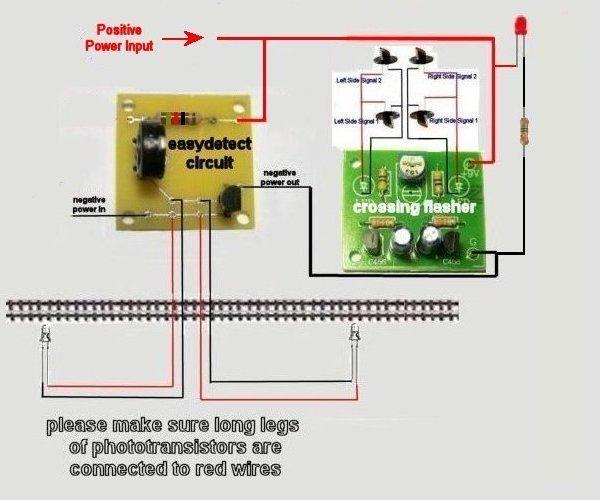
 Below is the wiring diagram for interfacing to our Crossing Flasher Kit and the Red Status Indicator both at the same")
13 Below is the wiring diagram for interfacing to our Crossing Flasher Kit ( The crossing flasher kit is not included but is for sale separately from the detector kit ) Below is the wiring diagram for interfacing to our Crossing Flasher Kit and the Red Status Indicator both at the same time
14

15 BELOW IS OUR WIRING DIAGRAM FOR INTERFACING OUR DETECTOR KITS TO A 12 VOLT DC RELAY Pictured below is a wiring diagram for interfacing with a generic 12 volt DC relay Things to bear in mind when interfacing to a relay 1. Relay Selection: your relay must be a relay whose coil will operate reliably with 12 volts dc and 20 milliamps or less of power 2. Your power supply for you load should not exceed the relays contact rating

16 Pictured below is a wiring diagram showing how to interface with the 12 volt relay we sell in our Detector with Relay Kit Things to bear in mind when interfacing to a relay 3. Relay Selection: your relay must be a relay whose coil will operate reliably with 12 volts dc and 20 milliamps or less of power 4. Your power supply for you load should not exceed the relays contact rating see the pictures below for proper placing of your phototransistors and extra lighting options if your layout room has dim lighting CONGRATULATIONS - That s it.you are done. Troubleshooting If the red led does not come on regardless of which way or how far you turn the calibration trimmer then check the following 1. are the phototransistors wired correctly so that the long leg of each phototransistor is connected to the correct wire that goes to the correct hole?
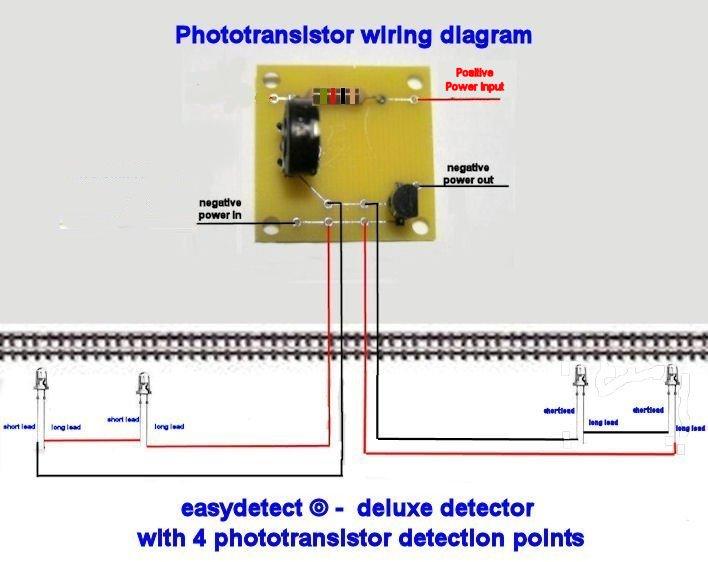
17 2. check to see that all your soldering connections are nice and strong 3. check to see that the 2n3904 transistor is installed facing the right direction 4. check to see that you have the positive and negative wires that power the kit are connected correctly to you 6-12 volt dc power source 5. MAKE SURE YOUR POWER SUPPLY IS DC NOT AC 6. check to see that your 6-12 volt power supply is turned on you can check that by connecting the red led/ 560 ohm resistor combination directly to your 6-12 volt dc power supply make sure the 560 ohm resistor is soldered to one leg of the led or it could blow up the led 7. check to see that the red led is wired correctly, if it is backwards, it wont hurt the kit, but it wont light up either 8. the detector will not work if you turn the lights off in your layout room or if the lights are not bright enough. One way around this would be to install light posts on your layout above the phototransistors see diagram below 9. Remember that at least one of the phototransistors need to be covered for the detector circuit to be activated. If your train is too short, you could have a situation where the detector comes on when the engine covers the first phototransistor, but shuts off before the train reaches the crossing because the 1st phototransistor gets uncovered before the 2 nd phototransistor gets covered Thanks again for purchasing our new train detector kit If you have any questions or problems please call us at or sales@quickar.com see illustration below for proper spacing of your phototransistors and for wiring the
18 phototransistors in our Deluxe 4 Point Detector kit
19
20
21
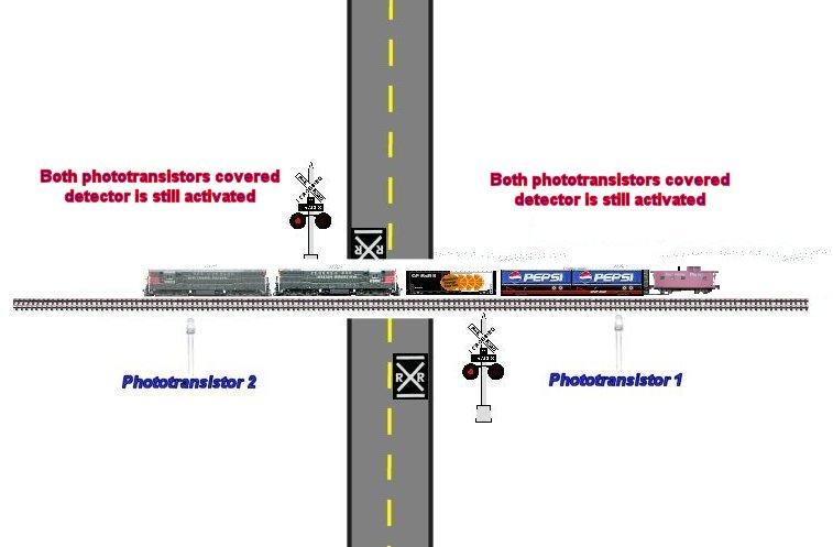
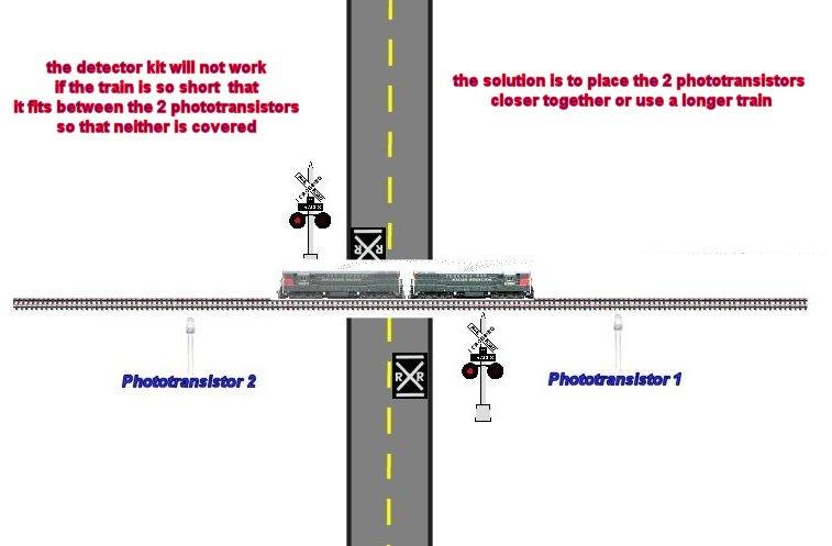
22 As shown in the above pictures, Please note that as long as at least one of the phototransistors is covered the detector is still activated, so if the train stops and backs up, as long as at least one phototransistor is covered, the detector will work. Things to remember before buying or installing your detector kit so your detector kit works properly 10. the detector will not work if you turn the lights off in your layout room or if the lights are not bright enough. One way around this would be to install light posts on your layout above the phototransistors see diagram below

23 Things to remember before buying or installing your detector kit so your detector kit works properly 11. Remember that at least one of the phototransistors need to be covered for the detector circuit to be activated. If your train is too short, you could have a situation where the detector comes on when the engine covers the first phototransistor, but shuts off before the train reaches the crossing because the 1st phototransistor gets uncovered before the 2 nd phototransistor gets covered. See picture below The remedy is to either move the two phototransistors closer together, or use a longer train or you can purchase our Deluxe Detector Kit that features 2 extra phototransistors for a total of 4 detection points See Wiring Diagram Below for wiring the 4 phototransistors in our Deluxe Detector Kit
24
25 Thanks again for purchasing our new train detector kit If you have any questions or problems please call us at or
easydetect and easydetect deluxe model train detector kits Quickar Electronics, Inc.
 easydetect and easydetect deluxe model train detector kits 2011-2012 Quickar Electronics, Inc. INSTRUCTIONS AND DIAGRAMS REVISED NOV 12 TH 2018 Please note that the color of the calibration trimmer may
Installation Instructions Azatrax HexDetex Model Train Detector with Grade Crossing Trigger MRD6X
 Installation Instructions Azatrax HexDetex Model Train Detector with Grade Crossing Trigger MRD6X What it is: The MRD6X is a six-channel model train detector. It can detect model trains at up to six different
Installation Instructions Azatrax Dual Infrared Model Train Detector MRD2 'Turnout' Edition
 Installation Instructions Azatrax Dual Infrared Model Train Detector MRD2 'Turnout' Edition What it is: The MRD2 'turnout' edition is a two-channel model train detector. It can detect model trains at two
How to modify Volvo Alarm Siren after it has given Message: Alarm system Service Required Ver. 1.2
 How to modify Volvo Alarm Siren after it has given Message: Alarm system Service Required Ver. 1.2 We will show how to modify the Alarm Siren Unit without using Battery. If you are not sure or do not know
Before you begin the installation process, gather the following tools and keep them handy:
 Vertical Blind Installation Instructions ucontact@udoblinds.com 1-855-205-8442 Congratulations on purchasing vertical blinds from Follow these instructions to properly install your blinds. Tools You Need
TrainBoss Defect Detector Displaying Detector Model No. TB-21D
 TrainBoss Defect Detector Displaying Detector Model No. TB-21D Hotbox & Equipment Defect Detector for model railroads Displays 6 types of defect alarms for passing trains: hotbox, dragging equipment, high
Installing and operating your Cabinet Cooling System, with Digital Thermostat
 NOTE: These instructions are for a standard system, since it is not possible to make separate instructions for every custom system. If you have requested a custom system, please be aware of the differences
Installing and operating your Enclosed Cabinet Cooling System and digital thermostat
 NOTE: These instructions are for a standard system, since it is not possible to make separate instructions for every custom system. If you have requested a custom system, please be aware of the differences
An Ambient-Light-Ignoring Infrared Active Motion Detector
 An Ambient-Light-Ignoring Infrared Active Motion Detector Design Team Members: Namita Ahuja Robert Mitchell Karl Schrader Michael Perry Joe Ha Table of Contents: Project Objectives Background Information
Saffire User & Installation Manual. IMPORTANT This manual should be left with the panel after installation.
 Saffire+ 8-12 User & Installation Manual IMPORTANT This manual should be left with the panel after installation. We reserve the right to change product specifications without prior notice. Copyright VRC
Sensing the World. When you have finished this lecture you should be able to:
 Free Course: How to build a real robot Lecture 3 Sensing the World MUSES_SECRET: L3, Adding the Brain: ORF-RE 2011-2012 Project - Dr. Alaa PAMI Khamis, Research IEEE Group RAS University Egypt Chapter
SERVICE MANUAL FOR MODEL RM-10
 SERVICE MANUAL FOR MODEL RM-10 REQUIRED TOOLS CORDLESS DRILL COPPER CUTTING TUBE 1/2 OPEN WRENCH SOLDERING IRON SCREWDRIVER SET WITH 9/32 SOCKET VISE GRIP PIERCING VALVE PRECISION FLAT BLADE SLOTTED SCREWDRIVER
Exercise 1. Introduction to Sensors EXERCISE OBJECTIVE
 Exercise 1 Introduction to Sensors EXERCISE OBJECTIVE When you have completed this exercise, you will be introduced to photoelectric, capacitive and inductive sensors; You will also be introduced to the
Magneplanar 20.7 Instruction Manual
 Magneplanar 20.7 Instruction Manual Table of Contents Quick Set-up Instructions 2 Introduction 3 General Description 3 Carton Contents 3 Packaging 3 Assembly 4 Tweeter Installation 4 Hookup 4 Caution 5
Models NFPA 1221-A, NFPA 1221-B Public Safety DAS Annunciator Panel. Revision E 61117
 Models NFPA 1221-A, NFPA 1221-B Public Safety DAS Annunciator Panel Revision E 61117 CAUTION: (Read This First) This panel has been designed to make it nearly bullet proof to mistakes made when wiring
AP Air Ion Counter Instructions
 AP Air Ion Counter Instructions Standard 2 million ions/cm 3 version- The 6 m long ground cord should be used to connect the meter to earth ground for most types of measurements - - especially if you are
MEGAbitty ProxDot Object Sensor Board (preliminary documentation) 5/1/2004
 5/1/2004") 1 Assembly notes: 1.) Install all SMD components, except the IR LEDs (D1&D2.) Be sure to orient the indicator LED (D3) correctly. Look carefully at the top side (glass side) of the LED -- you should see
1 Assembly notes: 1.) Install all SMD components, except the IR LEDs (D1&D2.) Be sure to orient the indicator LED (D3) correctly. Look carefully at the top side (glass side) of the LED -- you should see
Smart Grid Tables. Exploring the Electrical Infrastructure Grades 9-12
 Smart Grid Tables Exploring the Electrical Infrastructure Grades 9-12 Exploration 1 1. There are three power plants represented on the end of the grid table. List them here. Estimate how much (%) of the
Light Sensor Module (LSM01)
") Light Sensor Module (LSM01) LSM01 PCB May mount in Comfort CPU or SEP K1 LSM01 VR1 R2 U1 NC COM NO TO SENSOR TO MAIN + IN S- O/P GND 12V GND Photocell (Externally Mounted in transparent box or behind PIR
Light Sensor Module (LSM01) LSM01 PCB May mount in Comfort CPU or SEP K1 LSM01 VR1 R2 U1 NC COM NO TO SENSOR TO MAIN + IN S- O/P GND 12V GND Photocell (Externally Mounted in transparent box or behind PIR
THE. Series 01 and 02. MG01C Package
 THE Series 01 and 02 124 Springville Road Unit 3 Hampton Bays, New York 11946 Phone: (800) 648-4301 (631) 728-3986 Fax: (631) 728-3931 www.marineguard.net MG01C Package Each year, more people are turning
Polarized Retroflective Photoelectric Switches
 Exercise 5 Polarized Retroflective Photoelectric Switches EXERCISE OBJECTIVE In this exercise, you will be introduced to polarized retroreflective photoelectric switches; You will learn how and when they
LINKABLE UNDERCABINET
 Date: LINKABLE NK UNDERCABINET Model: SWWC10 Available in frosted lens SWWC10A (SWWC10 with ON/OFF switch) SWWC10D with Built-in Touch dimmer) Size Cambered Linear LED Light is perfect for installation
ED820-24V MODEL INSTRUCTION MANUAL. fire DETECTOR
 ED820 24V MODEL fire DETECTOR INSTRUCTION MANUAL Address: Enigma House, Enigma Business Park, Malvern, Worcestershire, WR14 1GD Tel: 44 (0)1684 891500 Fax: 44 (0)1684 891600 Email: sales@electronicdevices.co.uk
Electric, Liquid Filled & Hydronic Rails Installation Wiring Controlling Your Rail Stainless Steel vs Chrome Warranty Where can they be installed?
 Page 1 Heated Towel Rails are no longer a luxury, but are now becoming even more commonly seen as an inexpensive way to transform the bathroom experience. Used as both a design feature and a practical
INSTALLATION & OPERATION MANUAL
 INSTALLATION & OPERATION MANUAL Model TME- * * Balance of model number is determined by customer specifi ed limits and Setbacks. AUTOMATIC SETBACK THERMOSTAT LIGHT SENSING OR CONTACT CLOSURE FOR LOW VOLTAGE
Vance Dickason s LDC6 Home Theater System #
 Vance Dickason s LDC6 Home Theater System #300-655 Thank You.for purchasing the #300-655 Home Theater System. This system was designed by Vance Dickason and optimized using the sophisticated Linear X LMS/LEAP
Part 1: Playing with Electricity
 Foreword by Joe Grand... Acknowledgments... xix xxi Introduction xxiii About This Book...xxiv Who Should Read This Book...xxiv How to Read This Book....xxiv What s in This Book?....xxv Your Electronics
Azatrax Quad Infrared Proximity Detector Shield for ArduinoTM Uno, Mega and compatibles
 User's Guide Azatrax Quad Infrared Proximity Detector Shield for ArduinoTM Uno, Mega and compatibles RIR4 What it is: The RIR4 has four infrared (IR) proximity detectors assembled on a circuit board with
Combining Old and New Systems in Existing Buildings and Other Retrofit Tales. By Paul Jewett CFAA Technician Number 11
 Combining Old and New Systems in Existing Buildings and Other Retrofit Tales By Paul Jewett CFAA Technician Number 11 Combining Old and New Systems in Existing Buildings and Other Retrofit Tales Disclaimer
Always make sure to check the heating film before, during, and after installation of the floor covering.
 Installation of floor heating film for ceramic tiles, granite and other stone or composite flooring Read through this entire manual before starting installation. All electrical connections must be made
INSTALLATION AND TROUBLE SHOOTING MANUAL for all Models of Nova Kool Remote Condensing units & Cold plates.
 INSTALLATION AND TROUBLE SHOOTING MANUAL for all Models of Nova Kool Remote Condensing units & Cold plates. Thank you for choosing Nova Kool for your refrigeration needs. For over 20 years we have been
ACCURATE ELECTRONICS INC
 ACCURATE ELECTRONICS INC Page 1 of 7 Model 108078 2 Sept 09 WWW.ACCURATE.ORG PO BOX 1654 97075-1654 8687 SW Hall Blvd 97008 BEAVERTON OR USA 503.641.0118 FAX 503.646.3903 Practice Section 108078 Rev A
EnvironmentalMonitoring
 Datasheet Numerous sensors, detectors and expansion modules are available for the requirements in ambient and device monitoring. All units are self-developed by Neol so the highest technical requirements
Tips To Help Conserve Electricity
 Tips To Help Conserve Electricity AND REDUCE YOUR POWER BILL Cut Your Power Bill Nobody wants to pay more than necessary for power! But a lot of us do. And that hurts when you live in a place with warm
How to reduce ChiliCube noise level by
 How to reduce ChiliCube noise level by replacing fans Description for how to replace noisy fans which come with the ChiliCube with 3-speed fans which are quieter even on high, and allow speed selection.
EG-400 Fire Detection Monitor
 EG-400 Fire Detection Monitor For Engine and Generator compartments Owner s manual with installation instructions Revision 2.3 (10/1/07) Our Business is Your Safety and Peace of Mind! Jim Shepherd Toll
IMPORTANT. PLEASE NOTE: The infrared beam path MUST be kept clear of obstructions at all times!
 USER GUIDE English IMPORTANT PLEASE NOTE: The infrared beam path MUST be kept clear of obstructions at all times! Failure to comply may result in the Detector initiating a Fire or Fault signal. Contents
Wig-Wag (C) Light-Flashing Module Improves Aircraft Visibility
 Light-Flashing Module Improves Aircraft Visibility") www.periheliondesign.com Eric M. Jones 113 Brentwood Drive Southbridge MA 01550-2705 508-764-2072 emjones@charter.net Wig-Wag (C) Light-Flashing Module Improves Aircraft Visibility Late in World War II,
www.periheliondesign.com Eric M. Jones 113 Brentwood Drive Southbridge MA 01550-2705 508-764-2072 emjones@charter.net Wig-Wag (C) Light-Flashing Module Improves Aircraft Visibility Late in World War II,
Rectifier RC-series. Manual RC-series English MA doc. Manual Wall and 19 English
 Rectifier RC-series Manual RC-series English Manual Wall and 19 English Presentation The RC-series is a rectifier for either directly powering the load or for use together with batteries. It is designed
Victoreen Primalert 35 Area Radiation Monitor
 Victoreen 05-437 Primalert 35 Area Radiation Monitor Operators Manual March 2005 Manual No. 126011 Rev. 3 2003, 2005 Fluke Corporation, All rights reserved. Printed in U.S.A. All product names are trademarks
Solstice Kit Assembly Guide
 Solstice Kit Assembly Guide Introduction Parts Express Revision Date: 1/28/2015 Parts Express, Morel, and Jeff Bagby would like to thank you for purchasing the Solstice speaker kit! With this kit, you
CO2 Carbon Dioxide Sensor
 Environmental Devices Corporation Technical Data Sheet P/N HS-C02-6000 CO2 Carbon Dioxide CO2 Carbon Dioxide Sensor DESCRIPTION Patent Numbers Great Britain GB 2 401 432 & GB 2 403 291 Europe EP 1544603
Run Your Trains, Not Your Track!
 Digitrax Command Control Run Your Trains, Not Your Track! BDL168 LocoNet Occupancy Detector For 16 Detection Sections and up to 8 Transponder Zones All Scales Features n Occupancy Detection for 16 detection
ACCURATE ELECTRONICS INC PO BOX SW HALL BLVD BEAVERTON OR USA FAX
 Page 1 of 10 Model 10807800 January 2014 ACCURATE ELECTRONICS INC PO BOX 1654 97075-1654 8687 SW HALL BLVD 97008 BEAVERTON OR USA 503.641.0118 FAX 503.646.3903 WWW.ACCURATE.ORG Practice Section 10807800
Q1. Carefully read the following extract from a safety leaflet. Then answer the questions.
 Q1. Carefully read the following extract from a safety leaflet. Then answer the questions. An RCD adaptor is an automatic safety switch. It should be used when there is a particular risk of electric shock.
MVP-D-TEK Vehicle Loop Detector 9 Volts DC to 240 Volts AC. Operating Instructions
 MVP-D-TEK Vehicle Loop Detector 9 Volts DC to 240 Volts AC Operating Instructions We have designed the new MVP-D-TEK vehicle loop detector with the following objectives in mind: 1. Compact package to allow
Model 3300 Technical Support and Installation Manual
 Model 3300 Technical Support and Installation Manual Manual # T15011 Document Revision: A1 1. OVERVIEW 1 2. BASIC OPERATION 1 2.1 General 1 2.2 Field-of-View 2 2.3 Range 2 2.4 Environment 2 2.5 Configuration
Helicycle Crew Alerting System (CAS)
") Helicycle Crew Alerting System (CAS) CAS Logic Boards Mounted on Radio Trays (Only 3 left as of Aug 14 th.) 8/14/2015 page 1 OF 12 INTRODUCTION If you view my Monterey Bay Shoreline video on YouTube, you
Helicycle Crew Alerting System (CAS) CAS Logic Boards Mounted on Radio Trays (Only 3 left as of Aug 14 th.) 8/14/2015 page 1 OF 12 INTRODUCTION If you view my Monterey Bay Shoreline video on YouTube, you
Installation, Operating and Maintenance Manual
 STATUS ZONES CONTROLS FIRE FAULT DISABLED FIRE 1 2 3 4 5 6 7 8 TEST FAULT DISABLED 1 5 BUZZER SILENCE RESET 1 2 TEST 2 6 LAMP TEST 3 SUPPLY 3 7 SYSTEM FAULT 4 8 SOUNDERS ACTIVATE/ SILENCE 4 FAULTS INSTRUCTIONS
DSP-13 Tri-Axis Detection (TRIAD TM ) System
 System") User Manual DSP-13 Tri-Axis Detection (TRIAD TM ) System DSP-13M_MAN_G 09/05/18 Page 1 of 24 Pros Who Know Trust Diablo 1. Contents 2. Table of Figures... 3 3. Introduction... 4 4. Technical Data... 5
User Manual DSP-13 Tri-Axis Detection (TRIAD TM ) System DSP-13M_MAN_G 09/05/18 Page 1 of 24 Pros Who Know Trust Diablo 1. Contents 2. Table of Figures... 3 3. Introduction... 4 4. Technical Data... 5
Smith's Heater Core DIY version
 Smith's Heater Core DIY version Some time ago there was an article in the LRO about how to make a new core for the old round Smith's heaters that involved wrapping a number of loops of 8mm diameter micro
MWS3 Ceiling Mount Microwave Occupancy Detector
 MWS3_0916/ISSUE1 MWS3 Ceiling Mount Microwave Occupancy Detector Description: the MW3SA offers a unique presence/absence detection capability by using an adjustable head. This incorporates an innovative
KITCHEN INSTALLATION GUIDE
 KITCHEN INSTALLATION GUIDE The step-by-step guide to installing your new kitchen right This brochure is your guide to preparing and installing your new kitchen yourself. Inside you ll find tips and ideas,
Installation Guide and Operating Manual MAN0932_V1_ _Rev B_08-12
 Fire Sentry Model SS3 Multi-Spectrum Digital Electro-Optical Fire Detectors (Models SS3-A, SS3-AN, SS3-AB, and SS3-ABN) Stand-Alone Mode or FS2000 System Mode Fire Sentry Corporation Document No. 1508-002
SERVICE MANUAL FOR MODEL RM-49
 SERVICE MANUAL FOR MODEL RM-49 REQUIRED TOOLS CORDLESS DRILL DRIVE CUTTING TUBING OPEN WRENCH OF 1/2 RATCHET WITH SOCKET OF 7/16 SCREWDRIVER SET WITH SOCKET OF 9/32 VISE GRIP PIERCING VALVE WATCHER SLOTTED
Magneplanar 3.7i Instruction Manual
 Magneplanar 3.7i Instruction Manual Table of Contents Quick Set-up Instructions 2 Introduction 3 General Description 3 Carton Contents 3 Packaging 3 Assembly 3 Hookup 4 Caution 4 Speaker Placement 4 Bass
General System Layout Sketch
 General System Layout Sketch EZ-37 Solar Panels PV panel Can use Standard Copper, CPVC or PEX Pipes Pump Existing Water Heater Bottom Feed Connector 1 Introduction This document describes how to install
SERVICE MANUAL FOR MODEL RM-26
 SERVICE MANUAL FOR MODEL RM-26 REQUIRED TOOLS CORDLESS DRILL DRIVE CUTTING TUBING OPEN WRENCH OF 1/2 RATCHET WITH SOCKET OF 7/16 SCREWDRIVER SET WITH SOCKET OF 9/32 VISE GRIP PIERCING VALVE WATCHER SLOTTED
How Home Thermostats Work by Karim Nice
 Search HowS Computer Stuff Auto Stuff Electronics Stuff Science Stuff Home Stuff Stuffo Health Stuff Mon Main > Home > Home Appliances Click here to go back to the normal view! How Home Thermostats Work
EIC SOLUTIONS, INC. Thermoelectric Air conditioner installation and operation manual. FOR 1500 Btu MODEL # S
 EIC SOLUTIONS, INC. Thermoelectric Air conditioner installation and operation manual FOR 1500 Btu MODEL # S AAC-145-T-E AAC-145-4XT-E AAC-145-T-E-HC AAC-145-4XT-E-HC AAC-145-XXXXX Cooling Solutions for
Single Point Freeze Protection Heat Trace Control TRACON MODEL FPT 130 Installation and Operation Manual
 We manage heat MANUAL Single Point Freeze Protection Heat Trace Control TRACON MODEL FPT 130 Installation and Operation Manual 1850 N Sheridan Street South Bend, Indiana 46628 (574) 233-1202 or (800) 234-4239
HUMIDITY MANAGEMENT MODULE TYPE H122 Digital USER INSTRUCTIONS
 HUMIDITY MANAGEMENT MODULE TYPE H122 Digital USER INSTRUCTIONS Contents Section Subject Page 1 Introduction 2 2 Unpacking 2 3 Principle of Operation 3 4 Installation 3 5 Operation 5 6 Routine Maintenance
TM channel block occupancy detector for LocoNet
 TM-56322 8-channel block occupancy detector for LocoNet User's manual 2016 BioDigit Ltd. All rights reserved. It is forbidden to reproduce and/or publish the contents of the present document in any form
Pipe Freeze Protection Control SCFP-CO-F130 Installation and Operation Manual
 MANUAL Pipe Freeze Protection Control SCFP-CO-F130 Installation and Operation Manual Model FPT 130 Single Point Freeze Protection Heat Trace Control Table of Contents SCFP-CO-F130 Overview... 3 Installation...
Hoffman Controls 759-ECM. Installation & Operating Instructions. Introduction. Installation. Pre-Installation Information/ Instruction
 Hoffman Controls Installation & Operating Instructions Introduction CAUTION Failure to read and understand the accompanying instructions and diagrams prior to energizing the Controller may result in permanent
l High precision, computer-designed parabolic optical system,. Dual element pyro-electric sensor.
 GENERAL INFORMATION: The No. 1852 provides 12 zones of coverage with a range of up to 25 feet (at a typical mounting height of 7-0 ). This model has the following important features: l High precision,
Technical Manual. VFD / Cabinet Heater Upgrade 110 VAC Heater to 12 VDC Heater. Provided by: Chart Inc.
 Technical Manual VFD / Cabinet Heater Upgrade 110 VAC Heater to 12 VDC Heater Provided by: Chart Inc. 407 7th Street NW New Prague, MN 56071 USA (800) 400-4683 Part Number 20977233 Rev. A 2016 Chart Inc.
INSTALLATION INSTRUCTIONS
 INSTALLATION INSTRUCTIONS The SensorNet I/O Module provides attachment for up to 32 alarms and up to 16 switched devices. An RS-232 or RS-422 communications port is also provided for receiving serial alarms.
Magneplanar 1.7i Instruction Manual
 Magneplanar 1.7i Instruction Manual Quick Step-Up Instructions Remove the steel magnetic strip from the front of the speakers. If the fabric sticks to the diaphragm, use a high tack tape to gently pull
Public Safety DAS Annunciator Panel
 Public Safety DAS Annunciator Panel 120 VAC Models: 1221-A, 1221-B, 1221-C Revision D 91117 48 VDC Models: 1221-A-48, 1221-B-48, 1221-C-48 24 VDC Models: 1221A-24, 1221-B-24, 1221-C-24 CAUTION: (Read This
D-Tect 2 GJD300 Quad PIR Movement Detector
 D-Tect GJD0 Quad PIR Movement Detector Package Contents 3. Package Contains: x D-Tect x Drilling template for fixing holes x Allen Key 3 x 3.75mm wall plugs 3 x 3.75mm screws x Spare Sliding Curtains x
MODEL FPT-130 SINGLE POINT FREEZE PROTECTION HEAT TRACE CONTROL
 TRACON MODEL FPT-130 SINGLE POINT FREEZE PROTECTION HEAT TRACE CONTROL TABLE OF CONTENTS FPT 130 Overview... 2 Installation... 3 Power Source and Load Connections... 4 Temperature Sensor... 5 External
USING ANCILLARY SIGNAL DEVICES TO IMPROVE SAFETY AT RAIL/HIGHWAY GRADE CROSSING SIGNALS
 APPLICATION NOTE AN-001 USING ANCILLARY SIGNAL DEVICES TO IMPROVE SAFETY AT RAIL/HIGHWAY GRADE CROSSING SIGNALS Summary This application note addresses how to improve safety regarding two potentially unsafe
LINEAR HEAT DETECTION CABLE DURÁN-SAFE
 LINEAR HEAT DETECTION CABLE DURÁN-SAFE Installation & User Manual 2018 DURAN ELECTRONICA S.L. - All rights reserved www.duranelectronica.com I-manSAFECABLE-v05 TABLE OF CONTENTS Pages 1. INTRODUCTION...
PNC 1000 SERIES 2, 4, 8 Zone Fire Alarm Control Panel
 PNC 1000 SERIES 2, 4, 8 Zone Fire Alarm Control Panel INSTALLATION, OPERATION AND MAINTENANCE MANUAL Version: CN-PM-1000.VER1.1-12/2012 EN54 INFORMATION In accordance with EN 54-2 clause 13.7, the maximum
The ENSA Wireless Automated Light Switch provides:
 Introducing the ENSA Wireless Automated Light Switch From It s The Magic Product That Every Monitored Alarm Salesperson Has Dreamt Of 2 The ENSA Wireless Automated Light Switch provides: 1. INCREASED SECURITY:
5245 / Thermotouch 4.3dC. Dual Control Thermostat. Installation & User Guide
 5245 / 5246 Thermotouch 4.3dC Dual Control Thermostat Installation & User Guide D U A L C O N T R O L S Y S T E M Contents Compatibility... 3 What s in the box?... 4 Before you start... 5 Installing Thermotouch...
FlashGuard 3000B Dual Lighting System Troubleshooting Guide
 FlashGuard 3000B Dual Lighting System Troubleshooting Guide Table of Contents Section Flashhead (Strobe) Troubleshooting Flowchart 1 Multiple Strobe Troubleshooting Flowchart 2 Sidelight Troubleshooting
FLT93 Installation, Operation and Troubleshooting Guide
 FLT93 Installation, Operation and Troubleshooting Guide Pre-Installation A. To get the best results from the instrument, the instrument should be mounted 20 pipe diameters downstream from any valve, pipe
Philco Restoration
 Philco 42-322 Restoration 11/24/2012 Purchased 42-322 on ebay for $51.50 plus shipping for total $68.79. 12/4/2012 Began restoration. Purchased schematics from Philcorepairbench.com 42-322Schematic-PA
D-TECT Introduction. Connecting the Unit. Quick Installation. Multi Beam Alignment & Masking. Mounting the Unit
 D-TECT 2 GJD300 Quad PIR Movement Detector Package Contents Package Contains: 1 x D-Tect 2 1 x Drilling template for fixing holes 3 x 31.75mm wall plugs 3 x 31.75mm screws 2 x Spare Sliding Curtains 2
UNDERWATER CAMERA HOUSING LEAK DETECTOR
 UNDERWATER CAMERA HOUSING LEAK DETECTOR Thanks for purchasing our Underwater Camera Housing Leak Detector. This device is designed to give early warning to underwater photographers of small water leaks
INSTALLATION INSTRUCTIONS FOR ENTRANCE CONTROL SYSTEM MODEL GL-RO-3
 INSTALLATION INSTRUCTIONS FOR ENTRANCE CONTROL SYSTEM MODEL GL-RO-3 DATE ISSUED 7/2008 GOODLIN SYSTEMS INC. www.goodlinsys.com CONTENTS INTRODUCTION Pg 2 SPECIFICATIONS Pg 2 DETECTION FIELD THEORY Pg 3
WD-CS. Water leak detection cable. Technical Overview. Features. Page 1. Data Sheet Ref: Issue: 5.1.
 Data Sheet Ref: 90501085 WD-CS Water leak detection cable Technical Overview The WD-CS range of cable sensors are typically used to detect water leaks usually under floors, and are used in conjunction
an ISO 9001:2008 Registered Company GOLL ST. - SAN ANTONIO, TX ph fax MINI SPACE SAVER HEAT /COOL
 an ISO 9001:2008 Registered Company 18865 GOLL ST. - SAN ANTONIO, TX. - 78266 - ph.210-654-7171 - fax 210-654-3113 MINI SPACE SAVER HEAT /COOL 01000-QUX-A 01000-VUX-A 900101-VUX-A REV C 3/5/14, MINI SPACE
360º FLUSH MOUNT CEILING PIR LIGHT CONTROLLER INSTALLATION & OPERATING. Cat No. SLFM360 INSTRUCTIONS
 360º FLUSH MOUNT CEILING PIR LIGHT CONTROLLER Cat No. SLFM360 INSTALLATION & OPERATING INSTRUCTIONS 1 Introduction The SLFM360 utilises passive infrared technology to detect heat radiation of moving human
Oreck Edge - Upright Tune-Up & Service Guide 02/26/2010
 The Oreck Manufacturing Company Oreck Edge - Upright Tune-Up & Service Guide 02/26/2010 Compiled by Clark DeNoble 1 Table of Contents Electrical Page 3 Tune-Up Evaluate Page 4 Clean Page 4 Replace Page
Ceiling Microwave presence detector - DALI / DSI 12-24V AC/DC. Microwave Sensor. IR Receiver. Light Level Sensor. Status LEDs.
 MWS6-DD-LV Product Guide Ceiling Microwave presence detector - DALI / DSI 12-24V AC/DC Overview The MWS6-DD-LV microwave presence detector provides automatic control of lighting loads with optional manual
Motorised Infrared Optical Beam Smoke Detector. User Guide
 Motorised Infrared Optical Beam Smoke Detector User Guide EN 1. General Information 50cm 50cm 8-100m Ensure clear line of sight from Detector to Reflector Mount on solid surfaces (structural wall or girder)
SEA FROST BD 12 OR 24-VOLT D.C. AIR-COOLED SYSTEM
 148 OLD CONCORD TURNPIKE BARRINGTON, NH 03825 USA TEL (603) 868-5720 FAX (603) 868-1040 1-800-435-6708 E-Mail:sales@seafrost.com www.seafrost.com SEA FROST BD 12 OR 24-VOLT D.C. AIR-COOLED SYSTEM CONDENSING
CAR BURGLAR ALARM K3504
 CAR BURGLAR ALARM K3504 Low cost reliable car alarm. ILLUSTRATED ASSEMBLY MANUAL H3504IP - 1 Features & Specifications The alarm detects sudden voltage drops of the battery when the interior, trunk, or
REV: 000. Mercury Compact Series
 REV: 000 Mercury Compact Series Table of Contents Introduction 2 Standard Operating Guide 2 Features & Specs 2 External Layout 3-8 Internal Layout 9-12 Wiring Diagram 13 F.A.Q. 14-22 Comprehensive Parts
Selecting Fans and Determining Airflow for Grain Drying and Storage
 Proceedings of the Integrated Crop Management Conference Proceedings of the 1993 Integrated Crop Management Conference Dec 2nd, 12:00 AM Selecting Fans and Determining Airflow for Grain Drying and Storage
The diagram shows the inside of an incorrectly wired three-pin plug. What two changes need to be made so that the plug is wired correctly?
 1 (a) The diagram shows the inside of an incorrectly wired three-pin plug. (i) What two changes need to be made so that the plug is wired correctly? 1... 2... (ii) The fuse inside a plug is a safety device.
MODEL EUR -5A AUTOMATIC SNOW/ICE MELTING SYSTEM CONTROL PANEL
 MODEL EUR -5A AUTOMATIC SNOW/ICE MELTING SYSTEM CONTROL PANEL TABLE OF CONTENTS Product Overview... 2 Operation... 3 Installation... 5 Troubleshooting... 9 Ordering Information, Warranty and Service...10
For assistance with the product please contact: HELPLINE. For a product brochure please contact:
 For assistance with the product please contact: HELPLINE 020 8450 0515 or email helpline@timeguard.com For a product brochure please contact: Timeguard Limited. Victory Park, 400 Edgware Road, London NW2
Time Sow seeds: 30 min First seedlings: A few days Cress: About 1 week
 Sow seeds: 30 min First seedlings: A few days Cress: About 1 week Cress seeds Small bowls to sow seeds in Soil or cotton wool Plastic We put cress seeds on damp cotton or in moist soil and cover with plastic.
Automatic Night Lamp Circuit Diagram Using Ldr And Triac
 Automatic Night Lamp Circuit Diagram Using Ldr And Triac During day time the LDR has low resistance and keeps the pin 12 of the IC1 high, That means the high output drives the triac to switch on the lamp
EcoBrite Smooth Light LED Light Fixtures
 Installation Guide EcoBrite Smooth Light LED Light Fixtures BEFORE YOU BEGIN INSTALLATION Read these instructions carefully. Failure to follow these instructions will invalidate the warranty on this product
Alpha In-Wall Speaker 10-Inch Carbon Fiber 300W Subwoofer
 Alpha In-Wall Speaker 10-Inch Carbon Fiber 300W Subwoofer P/N 30487 User's Manual CONTENTS SAFETY WARNINGS AND GUIDELINES... 3 INTRODUCTION... 4 FEATURES... 4 CUSTOMER SERVICE... 4 PACKAGE CONTENTS...