Model SRPM Room Pressure Monitor. Installation and Operating Manual
|
|
|
- Emmeline Washington
- 6 years ago
- Views:
Transcription
1 Model SRPM Room Pressure Monitor Installation and Operating Manual 1

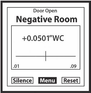
2 Setra SRPM Room Pressure Monitor The Setra SRPM Room Pressure Monitor is designed for critical low differential pressure applications that require stringent pressure monitoring and alarming. The SRPM can be confi gured to monitor positive, negative or neutral pressure in protected environments and hospital isolation rooms per CDC guidelines. The SRPM is a complete system that includes a backlit RGB LCD display with a graphic user interface, which enables access to pressure, security, calibration, and alarm setup. The touch-screen displays menus that guide the user through setup, as well as setting up password protection. Red and green LED s and a local audible alarm (with time delay feature) alert personnel to system status. The SRPM has a NEMA 1 (IP20) rated fire retardant plastic housing for indoor applications. True differential pressure is displayed with a resolution of Setra s patented very low pressure capacitance sensor is dead ended and avoids the potential for cross contamination of the room and reference space as well as eliminating drift that results from fouling of flow based sensors, which by nature have a flow path connecting the protected and reference spaces. Additionally there are 2 levels of password protection available as well as optional BACnet MSTP communications. 2
3 Table of Contents 1.0 Intended Use Specifi cations SRPM Function Parts SRPM Included parts SRAN Included parts RPS included parts Parts required and to be supplied by installer Installation Wiring (Rough in) Plumbing Wiring (Finish) Alarm Relay Remote Annunciator Door status input Analog Output BACnet Startup and Operation Menu Tree Power Up Monitoring Screen Main Menu Setup Unit Setup Room Setup Alarms Self Test Calibration BACnet Setup Screen Remote Annunciator Maintenance Agency Electrical Standards Wiring and Plumbing Overview Menu Tree
4 1.0 INTENDED USE The SRPM is designed to monitor critical environments by providing differential pressure indication. Typically this is between a monitored room and a reference space such as a corridor or ante room. The unit also provides monitoring, alarm and communications functions. Installation must be indoors, Polution Degree 2, Installation Category II. Typical Applications: 1. Hospitals patient isolation and protection rooms, operating suites, intensive care, and emergency rooms. 2. Pharmaceutical, semiconductor, precision manufacturing, and clean rooms. 3. Laboratories medical research, BSL (Bio safety labs), radiation, vivarium, toxic metals and chemicals. Indoor use only. 1.1 SPECIFICATIONS Service: Air or nonconductive, nonexplosive gases. Accuracy: ±0.5% F.S., ±0.25% FS optional Operating Temperature Limits: 32 to 120 F (0 to 50 C). Operating Humidity Limits: 5 to 95% Relative humidity (non-condensing). Altitude: 2000 meters (max). Thermal Effects: ±0.03% F.S./ F (± 0.05% F.S./ C). Overpressure: ±15 WC. Supply Voltage: Code V1 and V VAC, Hz Code A1 and A VAC, Hz. Power Consumption (Voltage output): 5 W. Output: Selectable 4-20 ma (2-wire), 0-5 VDC (3-wire), or 0-10 VDC (3- wire). Loop Resistance (4-20mA output): OHMS Ω. Electrical Connection: Removable terminal block. Pressure Fittings: Barbed fittings for 1/4 O.D. tubing. Housing: Fire retardant plastic (NEMA 1, IP20 rated for indoor applications). Mounting: Mounts to customer supplied 4½ x 4½ plaster ring (mounts to double gang electrical box). Dimensions: 8½ H x 5.4½ W x 1.8½ D (20.3 H x 13.7 W x 4.1 Weight approx.): 1.5 lbs (680 g). Agency Approval: CE, CAN/CSA-C22.2 NO Communications: BACnet MSTP ASC, optional, see setra.com for detailed PICS statement. 4
5 1.2 SRPM FUNCTION The SRPM senses very low differential pressure using high accuracy capacitive sensor technology. The pressure difference for these applications is the difference in static pressure between a critical environment room and its surrounding reference area (usually a hallway or another room). Maintaining and monitoring a static room pressure difference ensures that the critical environment room is either protected or isolated from a surrounding environment. Protection strategy requires a net positive room static pressure difference, while isolation requires a net negative static pressure difference. The SRPM can be programmed to monitor either positive or negative room static pressure. Low pressure sensing technology is coupled with multifunctional alarming and simple touch screen user interface with password security protection. The BACnet communication option allows the device to communicate with other BACnet devices to allow the supervisory system to change confi guration setups and monitor alarms in an open network. User Interface: LCD Display 128 x 128 COG module, with custom RGB LED backlight and custom 4-wire resistive touch screen RGB Backlight. The SRPM indicates the status of the room being monitored using visual backlight color. Color Green Yellow Red Status Room Pressure is within alarm limits Door is open. (Door input must be enabled) Room Pressure is outside alarm limits and alarm delay period has been exceeded and room is not in No Isolation mode. Visual Feedback: LEDs, green for normal, red for alarm Audible Feedback: Beeper will sound when pressure is out of range and alarm delay has timed out. Volume can be adjusted between 1 to 4 in relative sound levels up to the maximum level specifi cation of the beeper of 85 db at 4. Audible alarm can also be disabled. Quick Room Mode Change: Sometimes the room needs to be changed quickly from in use (Occupied) to out of use (No Isolation). This is accomplished by using 2 levels of password protection. The Operator level allows access to change room modes but no other changes. The Supervisor Level allows full access to all menus. In No Isolation mode no alarms are generated even if the pressure is outside limits. To change modes see page 22, Room Mode Change, for directions to change modes. 5
 INCLUDED PARTS Quantity 1 SRPM assembly 2 Barbed Couplings, Brass, Plated 2 1/4 inch Tubes, Silicone 4 6-32 x 1/2 Mounting Screws for connecting the SRPM Base to")

6 2.0 PARTS 2.1 SRPM (Setra Room Pressure Monitor) INCLUDED PARTS Quantity 1 SRPM assembly 2 Barbed Couplings, Brass, Plated 2 1/4 inch Tubes, Silicone x 1/2 Mounting Screws for connecting the SRPM Base to the plaster ring 2.2 SRAN (Setra Remote Annunciator) INCLUDED PARTS Quantity 1 Annunciator Assembly 2.3 RPS (Room Pressure Snubber) INCLUDED PARTS Quantity 1 Room pressure snubber Assembly 2.4 Parts required and to be supplied by installer MOUNTING AND WIRING To mount and install properly, the following components are required: NOT INCLUDED and required for each SRPM Quantity 1 Double Gang Metal Electrical Box with Grounding Stud 1 4 x 4 inch Metal Plaster Ring 1 Door Switch SPDT or SPST, N.O., as needed NOT INCLUDED and required for each remote annunciator and room pressure snubber Quantity 1 Single Gang Electrical Box 1/4 tubing as required to connect between the RPS (Room Pressure Snubbers) and the SRPM 6
7 3.0 INSTALLATION (See Section 8.0 for overview)! For 120/240 VAC Version, only CAUTION: Do not open or remove SRPM cover (tool required) with input power applied unless performed by a licensed electrician. Hazardous Live voltage is present at connector J3 when power is applied. Please observe the warning symbol (! ) near the J3 power connector. The SRPM is designed to be mounted on a standard double gang metal electrical box using a 4 x 4 inch plaster ring adaptor. After the rough in wiring and plumbing is performed remove the cover and mount the baseplate to the plaster ring adaptor using the supplied 6-32 x 1/2 long mounting screws. Note: The plaster ring external mounting face needs to be positioned flush to recessed, relative to the surface of the wall. Also note the orientation of the 4 mounting screws in the plaster ring, as the plaster ring is rotated 90 from conventional mounting. Note: In the following wiring sections, abbreviations are used (e.g. J1, P3). Please see section 8.0 for complete wiring diagrams with abbreviations. Electrical Box 4 x 4 inch Plaster Ring (Rotated 90 ) SRPM Metal Base SRPM Cover 3.1 WIRING ELECTRICAL BOX (ROUGH IN) Layout the system in terms of wiring: power, annunciator, analog output, BACnet, relay output and plumbing to connect to the monitored spaces (pressure taps). Bring all power, earth ground, signal, communications and analog output wiring into the 4x4 electrical box. Bring 1/4 O.D. tubing for 3/6 Barb fi tting into box. In order to conform to the CSA safety standard the electrical installer must comply with the following earth ground instructions. Pre-wire the electrical box with power (24 VAC or 120/240), and provide earth grounding to the electrical box. The safety ground path consists of four 6-32 x 1/2 metal screws that connect the SRPM metal base to the 4½ x 4½ metal plaster ring. The plaster ring must be grounded to the 4½ x 4½ electrical box by 2 metal mounting screws. The 4½ x 4½ electrical box must be connected to the building earth ground. It is also highly recommended to use armored cable (Type AC) for all the wiring in applications where high levels of radio interference may be present. 7
8 Power leads, analog output, door status, and annunciator wiring should be 14 to 22 AWG stranded wire. BACnet suggested wiring is 22 AWG stranded wire in a shielded cable, a +,-, Gnd (S) and shield should be run. This can be 2 twisted pairs with a separate cable shield. One twisted pair is used for communications, the second twisted pair can be used for communications ground and the shield wire can be connected to the other device shield wires. 8
 is installed in the monitored room.")

9 3.2 PLUMBING (ATTACHING PRESSURE TUBING) Warning: Always attach tubing to the SRPM header and then place Header onto SRPM. This will prevent overpressure from crimped or collapsed tubes. Use the following procedure for all room types: positive, negative or neutral: Typically a Room Pressure Snubber (RPS) is installed in the monitored room. Often stiff nylon ¼ tubing is used for running pressure signals from the SRPM to the monitored spaces. To prevent buckling and collapse of this stiff tubing inside the electrical box, use the supplied soft silicone tubing and tubing adaptors to transition from the fi eld tubing to the pressure fi ttings on the SRPM. Attach pressure tubing as follows: 1. Connect the 1/4 inch O. D. tubing running from the RPS (or other pressure connection from the monitored space) to the 4½ x 4½ electrical box for the SRPM. Install one of the supplied 1/4 inch male to male barbed tube adaptors onto the end of the tube then push the 4 length silicone tube (supplied) onto the other end. Thread the tubes, with installed adaptor, through the conduit opening at the bottom of the electrical box. 2. Next push the open end of the silicone tubing onto the SRPM pressure tube header (H1) port labeled +. Note: The header is an Electro-Pneumatic (EP) assembly. + indicates (Positive) pressure, and - indicates negative or reference pressure. 3. For the most pressure stable operation, an RPS installed in the reference pressure area is also recommended. In this case, install the RPS in a hallway or reference space. Attach the tube to the SRPM in the same way as for the + port, except attach the tube to the - port on the pressure tube header. Tighten swivel fi ttings on the SRPM Header H1 assembly if they become loose, 9 in lb. max. Verify that the tubes are not buckled, which could close off pressure signal at end of installation. Electrical Box Silicone Tubing RPS Tubing SRPM Header H1 Plumbing inside Electrical Box 9 1/4 O.D. Tubing RPS Room Pressure Snubber
10 3. 3 WIRING, FINISH ALARM RELAY OUTPUT The Single Pole Single Throw (SPST) relay output can be used for remote signaling of alarm condition. A form C contact rated at 1A is available. Connect to J4, P1 and P4 (See Section 8.0 for Diagram of J4). This relay can be used as a dry contact for remote indication or can drive an SRAN remote annunciator OPTIONAL REMOTE ANNUNCIATOR WIRING Setra SRAN wiring In the figure below, the SRAN remote annunciator connector is at left, and the SRPM connector is at right: On J4 of the SRPM, jumper P1 to P2, this will connect the internal 15V supply to the common of the internal alarm relay. Connect P2 to A1 (Located on Remote Annunciator), this supplies 15V exc. to the Annunciator for powering the circuit during normal conditions. Connect P3 of J4 to A2 of SRAN J1, this is the 15V power return. Finally connect P4 of SRPM J4 to A3 terminal of SRAN J1, this is the alarm trigger. When an alarm occurs and after the programmed alarm delay times out the internal relay will supply 15 V to the Annunciator circuit to actuate the audible beeper and the red LED. +15 VDC Excitation A1 Ground A2 J1: SRAN J4: SRPM P4 (Annunciator Trigger P3 (Ground) +15 VDC Trigger A3 Jumper P2 (+15 VDC Excitation) P1 (Relay N.O.) Non-Setra Remote Annunciator The SRPM can drive other annunciators that are powered by a 15V sup ply, 50 ma max current draw., and accept a 15V trigger (wire as above). 10
 clockwise to increase volume and counterclockwise to decrease volume. 3.")
11 Audible Alarm Potentiometer The volume control on the Annunciator is a potentiometer that can be adjusted from 0 to 85 db. Using a small fl at bladed screwdriver, rotate potentiometer (remote annunciator PC board) clockwise to increase volume and counterclockwise to decrease volume DOOR STATUS SWITCH WIRING Install the door switch into the door jamb. Wire to the normally open (N.O.) side of the door jamb contact switch. The SRPM will indicate the status of door position. A contact closure indicates that the door is closed. This is a low voltage circuit (5 VDC). Run 2 wires from the door switch to connector J6 on the SRPM (See Section 8.0). The door input status function is enabled in the SETUP ALARMS menu screen, section ANALOG OUTPUT The SRPM can be confi gured to have either current (4 to 20 ma) or voltage (0 to 5 or 0 to 10 VDC) outputs. Voltage output--pin 1, Current output--pin 2, Common--pin 3. Note: No external excitation is required.. Current Output The SRPM supplies it s own loop power, do not wire in a separate power supply. 1. V Out: 0 to 5, 0 to 10 VDC 2. C Out: 4 to 20 ma 3. Common + Receiver (ma) 11
12 Voltage Output 1. V Out: 0 to 5, 0 to 10 VDC 2. C Out: 4 to 20 ma 3. Common + Receiver (V) BACnet BACnet hardware is implemented as isolated RS485. Wire to Connector J2, labeled RS-485. Connect tx line to +(A), rx to (B) and ground wires to S. Connect Shields together with wire nut. Hardware confi guration is done using a 5 position dip switch (S1) located in the upper right hand section of the PCBA as well as through the touch screen interface, see Section 4.4. and 4.9. Position Function 1 MAC address enable 2 N/C Not Connected 3 Pull Up Resistor 4 Termination Resistor 5 Pull Down Resistor Use a small fl at blade screwdriver or pen to push the switch to the right to turn that function on, otherwise it is off. There is a BACnet setup screen that is enabled by pushing position 1 switch to the on position. After confi guration the switch must be moved to the off position. 12
13 4.0 STARTUP AND OPERATION The SRPM is designed with as an easy to use, intuitive, touch screen interface. In its normal (default) state the Monitoring Screen displays the actual room static pressure, also a slider bar shows the actual pressure relative to the alarm limits. The RGB backlight is used to indicate the condition of the room. The buttons at the bottom of the screen give you access to the functions that can be performed. 4.1 MENU TREE See section POWER-UP Apply power and observe the welcome screen and subsequent transition to the pressure monitor screen. The actual room static pressure is shown as a number in the center of the LCD and visually as a moving bar indicator operating between the preset alarm units. The vertical bar is an indicator of the pressure. 4.3 MONITORING SCREEN BUTTON Silence Menu Reset DESCRIPTION Shuts off Alarm Access to Main Menu Functions Resets the unit in Latched mode. 13

14 The following screens are confi guration screens, they can be confi gured so that Password protection is required to make changes. If no entry is made to the screen the unit will return to the default screen after approx. 1 minute. 4.4 MAIN MENU SCREEN BUTTON Unit Room Alarm BACnet Self Test Calibration Back DESCRIPTION Setup Supervisor password, output, engineering units, and display averaging. Set up high and low pressure limits to monitor a positive, negative, or neutral room.operator password setup. Setup latch alarm, audible alarm, door alarm input, mute time out, alarm delay, and volume. Confi guration of BACnet Communications Identifi es product model and software version, and serial #. Verifi es memory and performs alarm test. Perform zero and span calibration. Returns to monitoring screen. 14
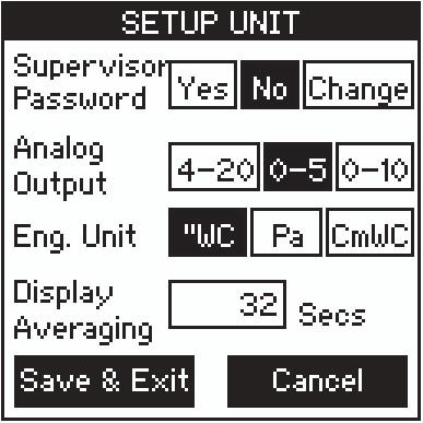
15 4.5 SETUP UNIT OPERATION ENTERING DATA Press (or tap) button to select an output or engineering unit. Selected button background will change from clear to black. PASSWORD PROTECTION Lightly pressing (or tapping) the Yes button activates Supervisor password protection. With Supervisor password protection enabled, operators can not access menu screens to update setup. Pressing No disables password protection. Pressing Change will open Password Setting Screen. To change the password, enter the present password (numeric value), followed by the new password in the New Password and Confi rm New Password entry boxes, then press save. Be careful to store password for future reference. Analog Output Select : 4-20, 0-5, or 0-10 Eng. Unit Select: WC, Pa, CmWC DISPLAY AVERAGING Lightly pressing (or tapping) the Display Averaging box activates the Data Entry Screen ). Enter from 0 to 60 seconds. Display averaging affects the analog output. Increase the display averaging time to smooth out the pressure readings, this will also reduce the display update rate. 15
 Erase any mistakes by using the Back Space key.")
16 Press Save and Exit. DATA ENTRY SCREEN Enter numbers by pressing each key in sequence until the desired character is displayed in the data entry box above the keypad. (Note: The cursor will blink for one to two seconds then stop and display the character.) Erase any mistakes by using the Back Space key. When fi nished entering data, press the Enter key to return to SETUP UNIT screen. Note: Use the eraser end of a pencil or back-end of a pen to press (or tap) box on screen to increase accuracy of inputs. 16
17 4.6 SETUP ROOM SCREEN SETUP ROOM OPERATION Setup alarm limits for protective positive room static pressure, isolating negative room static pressure or neutral (where the limits can be to +). ENTERING DATA Press lightly or tap in the Lower Limit data entry box. Enter the lower limit pressure. Enter the Upper Limit pressure. The Room type box will change depending on the lower and upper limits. If both entries are positive, the room will be a Positive Room. If both are negative, the room will be a Negative Room and if the Lower Limit is negative and the Upper Limit is positive the room will be a Neutral Room. OPERATOR PASSWORD The operator can only change the room from Occupied to No Isolation and vice versa. Lightly pressing (or tapping) the Yes button activates Operator password protection. With Operator password protection enabled, room Occupied/No Isolation status can not be changed without entering a valid Operator password. Pressing No disables password protection. Pressing Change will open Password Setting Screen. To change the password, enter the present password, followed by the new password in the New Password and Confi rm New Password entry boxes, then press save. Be careful to save the operator password for future reference. 17
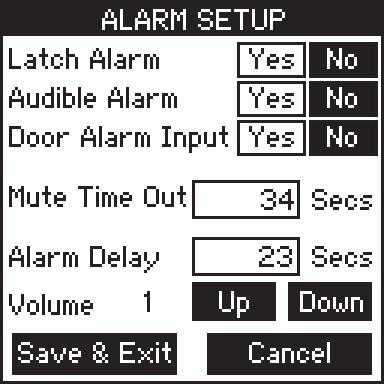
18 4.7 SETUP ALARMS SCREEN From this screen the user can access the following: a. Latched Alarm requires the pressure to return to normal and the alarm to be acknowledged before the alarm can be silenced and reset. b. Enable the audible alarm by selecting Yes or use visual only alarm by selecting No. c. Provide a door open warning visual indication. When a door jamb contact switch is used and this button is activated by pressing Yes, the door status open condition is indicated by the touch screen display turning from green to yellow, and door open indicated on the monitoring (default) screen. d. Set the time (in seconds) that the alarm can be silenced in the latched alarm mode before the alarm resumes. This assumes that the room static pressure is still outside the normal or set operating limits. The Mute Time Out can be set from 0 to 9999 seconds. e. Set the Alarm Delay (in seconds) from the time that the room pressure goes out of the preset limits until the alarm activates. The alarm delay may be set from 0 to 9999 seconds. f. Set the alarm volume or sound level. Using the Up and Down keys, the volume can be set at level 1-4. Level 4 alarm volume is the loudest and corresponds to a sound level of 85 db at a distance of 4 inches. ALARM SETUP OPERATION Lightly press (or tap) button to select Yes or No for Latch Alarm, Audible Alarm, or Door Alarm Inputs. Selected box background will change from clear to black when selected. MUTE TIME OUT/ALARM DELAY Pressing (or tapping) the Mute Time Out or Alarm Delay box activates the Data Entry screen to set the time delay duration. 18

19 4.8 SELF TEST SCREEN Self Test Operation This screen identifi es the Product Model Part Number and Software Version. User can also perform a Self Test of the unit to verify that the data in protected area of the EEPROM memory hasn t been corrupted and also test the alarm to verify the sound level and alarm setup. Press Self Test button to initiate EEPROM memory checksum test sequence. Press Alarm Test to test beeper, visual Red LED Alarm, and relay output. This can be used to verify the system in alarm mode. Press Cancel Test to stop the alarm test. Press Exit to return to Main Menu. 19
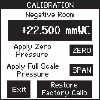
20 4.9 CALIBRATION SCREEN CALIBRATION To re-zero the device, disconnect the electropneumatic Header H1 so that room pressures are not applied to the pressure sensor and lightly press (or tap) the Zero button. If a sufficiently accurate Pressure Calibrator is available, apply a steady full-scale pressure signal to the + on the header fi tting and press (or tap) the Span button. Reconnect the room pressure tube and calibration is complete. Calibration must be within ±5% of original calibration for this to occur otherwise an error message will occur. The original factory pressure calibration can be restored, if desired, by pushing the Restore Factory Setting button. 20
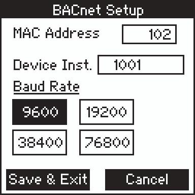
21 4.10 BACnet Setup Screen BACnet Setup To setup up BACnet communications, the MAC address enable switch (S1 [See Section 8]) on the dip switch must be enabled by pushing it to the right. Set MAC address, input the address of the device. Select Device Instance by inputting the device instance into the data entry box. Select baud rate by pressing the correct baud rate button, 9600 to Save and Exit to save settings or Cancel to cancel setting changes. Once complete disable the BACnet setup by moving the dip switch position 1 to off (left) position. If the unit will be at the end of the line, the pull up resistor can be enabled by pushing position 3 to on. The termination resistor can be inserted by pushing position 4 switch on. The pull down resistor can be enabled by turning position 5 to on. Save and Exit. After the unit returns to the main menu screen disconnect the power to the unit, then re-connect to boot up with the proper MAC address and Device Instance. Position Function 1 MAC address enable 2 Not Used 3 Pull Up Resistor 4 Termination Resistor 5 Pull Down Resistor See Setra website for information on Points list and PICS and BIBBS statements. 21

22 Click here to access ROOM MODE Screen PRESSURE MONITORING SCREENS At completion of setup, the main display will be the pressure monitoring screen, which displays the actual room static pressure.the room static pressure is shown as a number on the LCD as well as a Moving Bar indicator operating between the preset pressure limits. Normal room pressure conditions within the preset pressure limits are verifi ed by a green colored screen. When the door is opened under conditions within the preset pressure limits, the screen turns to yellow. Room static pressure outside of the preset limits is indicated by a Red screen after the alarm s time delay expires. CHANGING ROOM MODES The SRPM can quickly be changed from active monitor and alarming to No Isolation (or unoccuped). To do this touch the room mode indicator at the top of the pressure monitoring screen (see above). OCCUPIED/NO ISOLATION Use these buttons to quickly change the room to Occupied (Standby) or No Isolation status. If No Isolation is used there will be no alarms generated if the room is outside pressure limits. Press Save and Exit. 22
23 5.0 REMOTE ANNUNCIATOR Audible Alarm Green LED Red LED Acknowledge Switch The Remote Annunciator provides remote indication of room status. Green LED Red LED Audible Alarm Acknowledge Switch Visual indication of normal room condition. Visual indication of a breach in room pressure protection. Beeper sounds to indicate breach in room pressure protection. Press to silence beeper. OPERATION Under normal conditions, the green LED remains on. When an alarmed condition occurs (i.e., room pressure falls outside preset range), a signal is triggered by the SRPM, the green LED shuts off, the red LED fl ashes, and the audible alarm sounds. The acknowledge button can be pressed to momentarily turn-off the audible alarm and the red LED will continue to fl ash until the alarmed condition is corrected. When the alarmed condition is corrected the annunciator will reset itself. The green LED will turn on, and the red LED and audible alarm will shut-off. If the SRPM reaches the mute time out limit it will re-sound the alarm. 23
24 6.0 MAINTENANCE The SRPM is designed to operate in an indoor environment, monitoring clean, dry air. Upon fi nal installation of the SRPM Room Pressure Monitor, no routine maintenance is required. A periodic check of system calibration is recommended. The SRPM is not fi eld serviceable and should be returned if repair is needed (fi eld repair should not be attempted and may void warranty). Be sure to include a brief description of the problem plus any relevant application notes. Contact customer service to receive a return goods authorization number before shipping. CLEANING Important Do not blow into the pressure tubing or fi ttings with mouth, compressed air, or canned air. Such actions may permanently damage the pressure sensor. Do not clean or wash-down the SRPM with industrial cleaners or solvents. The housing may be wiped down with soap and water or isopropyl alcohol. The LCD may only be cleaned with isopropyl alcohol. Do not immerse unit. 24
25 7.0 AGENCY ELECTRICAL STANDARDS This device falls into CSA Pollution Degree 2 for PCB insulation and CSA Installation Category 2. The SRPM meets the following requirements: CSA Standard C22.2 No 0-M 91: General Requirements - Canadian electrical code, Part 1 CAN/CSA C22.2 No : Bonding of Electrical Equipment CAN/CSA-C22.2 No : Safety requirements for electrical equipment for measurement, control and laboratory Use Part-1: General Requirements ANSI/UL (Second Edition): Safety requirements for electrical equipment for measurement, control and laboratory use Part 1: General Requirements. 25
26 8.0 LOCATION OF COMPONENTS AND ACCESSORIES 26


27 9.0 MENU TREE 27
28 10.0 RETURNING PRODUCTS FOR REPAIR Before returning the unit for repair, please contact a Setra application engineer ( , ) to review information relative to your application. Many times only minor field adjustments may be necessary. When returning a product to Setra, the unit should be carefully packaged and shipped prepaid to: Setra Systems, Inc. 159 Swanson Road Boxborough, MA Attn: Repair Department To assure prompt handling, please refer to return instructions on our Web site at Allow approximately 3 weeks after receipt at Setra for the repair and return of the unit. Non-warranty repairs will not be made without customer approval and a purchase order to cover repair charges. Calibration Services Setra maintains a complete calibration facility that is traceable to the National Institute of Standards & Technology (NIST). If you would like to recalibrate or recertify your Setra pressure transducers or transmitters, please call our Repair Department at ( ) for scheduling WARRANTY AND LIMITATIONS OF LIABILITY Setra warrants its products to be free from defects in materials and workmanship, subject to the following terms and conditions: Without charge, Setra will repair or replace products to be found to be defective in materials or workmanship within the warranty period; provided that: a.) the product has not been subjected to abuse, neglect, accident, incorrect wiring not our own, improper installation or servicing, or use in violation of instructions furnished by Setra; b.) the product has not been repaired or altered by anyone except SETRA or its authorized service agencies; c) the serial number or product code has not been removed, defaced, or otherwise changed; and d) examination discloses, in the judgement of SETRA, the defect in materials or workmanship developed under normal installation, use and service; e) SETRA is notified in advance of and the product is returned to SETRA transportation prepaid. Unless otherwise specified in a manual or warranty card, or agreed to in a writing signed by a SETRA officer, SETRA pressure and acceleration products shall be warranted for one year from date of sale. The foregoing warranty is in lieu of all warranties, express, implied or statutory, including but not limited to, any implied warranty of merchantability for a particular purpose. SETRA s liability for breach of warranty is limited to repair or replacement, or if the goods cannot be repaired or replaced, to a refund of the purchase price. SETRA s liability for all other breaches is limited to a refund of the purchase price. In no instance shall SETRA be liable for incidental or consequential damages arising from a breach of warranty, or from the use or installation of its products. No representative or person is authorized to give any warranty other than as set out above or to assume for SETRA any other liability in connection with the sale of its products. For all CE technical questions, contact Setra Systems, USA. EU customers may contact our EU representative Hengstler GmbH, Uhlandstr 49, Aldingen, Germany (Tel: ; Fax: ). 159 Swanson Road, Boxborough, MA 01719, Tel: ; Fax: ; sales@setra.com; Web: 28 SS-SRPM351 Rev D 08/14/09
Series RSM Room Status Monitor. Specifications - Installation and Operating Instructions 5-13/32 [137.16] 8 [203.20] 4-5/8 [117.
![Series RSM Room Status Monitor. Specifications - Installation and Operating Instructions 5-13/32 [137.16] 8 [203.20] 4-5/8 [117.](/thumbs/92/109946408.jpg "Series RSM Room Status Monitor. Specifications - Installation and Operating Instructions 5-13/32 [137.16] 8 [203.20] 4-5/8 [117.") Series RSM Room Status Monitor Specifications - Installation and Operating Instructions Bulletin p-3-rsm 5-13/32 [137.16] 1-5/8 [41.66] 2-5/32 [55.12] 8 [203.20] 4-5/8 [117.09] TUBING HEADER PORT ROOM
Series RSM Room Status Monitor Specifications - Installation and Operating Instructions Bulletin p-3-rsm 5-13/32 [137.16] 1-5/8 [41.66] 2-5/32 [55.12] 8 [203.20] 4-5/8 [117.09] TUBING HEADER PORT ROOM
DPG300 SERIES M-5258/0213
 1 DPG300 SERIES M-5258/0213 OMEGAnet Online Service omega.com Internet e-mail info@omega.com Servicing North America: U.S.A: Omega Engineering, Inc., One Omega Drive, P.O. Box 4047 ISO 9001 Certified Stamford,
Setra Model SRH Relative Humidity Sensor Series with Active or Passive Temperature Sensing Installation Instructions
 Setra Model SRH Relative Humidity Sensor Series with Active or Passive Temperature Sensing Installation Instructions 1.0 GENERAL INFORMATION Every SRH humidity sensor product is tested and calibrated before
Analog Room Pressure Monitor RPC Series
 Description The Room Pressure Monitor is used to measure differential pressure in the range of 0.125 to 1"wc or 30 to 250 Pa. It combines precision high sensitivity silicon sensing capabilities and the
Oxygen (O2) Single-Point Gas Detection System
 Single-Point Gas Detection System") Oxygen (O) Single-Point Gas Detection System DESCRIPTION Wall-mounted gas monitor with built-in oxygen (O) sensor, accepts one analog remote device such as a secondary gas sensor, temperature or humidity
Oxygen (O) Single-Point Gas Detection System DESCRIPTION Wall-mounted gas monitor with built-in oxygen (O) sensor, accepts one analog remote device such as a secondary gas sensor, temperature or humidity
Nitrogen Dioxide (NO2) Single-Point Gas Detection System
 Single-Point Gas Detection System") Nitrogen Dioxide (NO) Single-Point Gas Detection System DESCRIPTION Wall-mounted gas monitor with built-in nitrogen dioxide (NO)/diesel fume gas sensor, accepts one analog remote device such as a secondary
Nitrogen Dioxide (NO) Single-Point Gas Detection System DESCRIPTION Wall-mounted gas monitor with built-in nitrogen dioxide (NO)/diesel fume gas sensor, accepts one analog remote device such as a secondary
GG-2 2-CHANNEL GAS DETECTION CONTROL PANEL. Installation and Operation Manual
 GG-2 2-CHANNEL GAS DETECTION CONTROL PANEL Installation and Operation Manual 2 GG-2 Warning Use this product only in the manner described in this manual. If the equipment is used in a manner not specified
Beacon 800 Gas Monitor Operator s Manual
 Beacon 800 Gas Monitor Operator s Manual Part Number: 71-0037RK Revision: F Released: 4/18/17 www.rkiinstruments.com Product Warranty RKI Instruments, Inc. warrants gas alarm equipment sold by us to be
GASGUARDIAN Channel Controller OPERATING & INSTALLATION MANUAL
 GASGUARDIAN 2 3 2-Channel Controller OPERATING & INSTALLATION MANUAL GasGuardian 2 3 Operating and Installation Manual Table of Contents General description.... 3 Installation. 3 Locating the GasGuardian-2..
Beacon 410A Gas Monitor Operator s Manual
 Beacon 410A Gas Monitor Operator s Manual Part Number: 71-0397 Revision: F Released: 12/5/17 www.rkiinstruments.com Product Warranty RKI Instruments, Inc., warrants gas alarm equipment sold by us to be
Carbon Monoxide Transmitter
 Introduction The CO Transmitter uses an electrochemical sensor to monitor the carbon monoxide level and outputs a field-selectable 4-20 ma or voltage signal. The voltage signal may also be set to 0-5 or
RPM1600 Series Room Pressure Monitors
 RPM1600 Series Room Pressure Monitors Technical Bulletin LB-RPM1611-0, LB--0 Code No. LIT-12012228 Issued October 2017 Refer to the QuickLIT website for the most up-to-date version of this document. How
Two-Channel Gas Controller
 Two-Channel Gas Controller Specifications subject to change without notice. USA 09 Page of DESCRIPTION Highly configurable, UL 0 performance-tested and -certified, and wall-mounted gas monitor; continuously
Mark 25 Ultrapure Water Conductivity Analyzer
 Martek Instruments, Inc. Mark 25 Ultrapure Water Conductivity Analyzer Instruction Manual WARRANTY POLICY Unless otherwise stated, MARTEK INSTRUMENTS, INC. warrants this equipment to be free from defects
VA301C CONTROLLER WITH BACnet OPTION
 ORDERING INFORMATION VA301C Controller VA301C-DLC VA301C-DLC-BIP Gas detection controller with data logging, display and plastic housing. Gas detection controller with data logging and display, BACnet/IP
Static Pressure Control
 The (model SPC-2) is a fully programmable controller that provides extensive flexibility for your curtain or awning control needs. The SPC-2 automatically controls the pressure in a room by operating a
AMC-RAM-4. Refrigerant Alarm Module USER MANUAL. Please read the installation and operating instructions completely and carefully before starting.
 AMC-RAM-4 Refrigerant Alarm Module USER MANUAL IMPORTANT: Please read the installation and operating instructions completely and carefully before starting. Filename: 3310405B, DOC, AMC_RAM4_Manual.doc
Long Range Radio Alarm Transmitter
 TM Long Range Radio Alarm Transmitter INSTALLATION MANUAL Version 1.3W FEATURES Transmits alarm information to a long range radio network Varitech Transmission Format Note: If automatic SIA is used in
Multiview Monitor / Controller
 FEATURES: Bright/sunlight readable 7.0 LCD touch screen. Displays large, easy to read values, set points, room status, modes and alarms Up to six fully configurable Icons including: Environmental points
Model 405 AIRGARD Fume Hood Monitor
 INSTALLATION AND MAINTENANCE INSTRUCTIONS Model 405 AIRGARD Fume Hood Monitor A TSI Company Model 405 AIRGARD Fume Hood Monitor Specifications Instrument Dimensions Instrument Weight Shipping Weight Green
INSTALLATION. and INSTRUCTION MANUAL. for QUALITY AIR BREATHING SYSTEMS. Model ABM - 715
 INSTALLATION and INSTRUCTION MANUAL for QUALITY AIR BREATHING SYSTEMS Model ABM - 715 M A R T E C H S E R V I C E S C O M P A N Y P.O. Box 7079 OFFICE: 800-831-1525 Mazeppa, MN 55956 Fax : (507)843-4953
Operating & Maintenance Manual. Alert-4 Ethernet LCD Master Alarm
 Operating & Maintenance Manual Alert-4 Ethernet LCD Master Alarm w w w. a m i c o. c o m Contents User Responsibility 4 Introduction 4 Features 5 Description of the Alarm 5 Shipment Details 5 The Alarm
GasScanner 8C. Eight Channel Monitor. Operator s Manual. MINT-0281-XX Rev. A 01/29/08
 GasScanner 8C Eight Channel Monitor Operator s Manual MINT-0281-XX Rev. A 01/29/08 Product Warranty Matheson Tri-Gas, Inc., warrants gas alarm equipment sold by us to be free from defects in materials,
Model SRCM Operation
 Model SRCM Operation 1 Contents OPERATION... 4 Condition Banner... 6 Condition Banner Touch Screen... 7 Operation... 7 Alarms Cause Condition Banner to Turn Red... 7 Condition Banner Functions... 7 Operating
Duct and Rough Service Carbon Monoxide Sensor
 Product Identification and Overview Duct and Rough Service Carbon Monoxide Sensor BAPI s Carbon Monoxide Sensor offers enhanced electrochemical sensing with outstanding accuracy at low concentrations.
GasScanner 4C. Four Channel Monitor. Operator s Manual. MINT-0280-XX Rev. A 02/25/08
 GasScanner 4C Four Channel Monitor Operator s Manual MINT-0280-XX Rev. A 02/25/08 Product Warranty Matheson Tri-Gas., warrants gas alarm equipment sold by us to be free from defects in materials, workmanship,
FUME HOOD MONITOR ALNOR AIRGARD 200
 FUME HOOD MONITOR ALNOR AIRGARD 200 OWNER S MANUAL P/N 116670080, REV 09 SEPTEMBER 2014 LIMITATION OF WARRANTY AND LIABILITY (effective April 2014) (For country-specific terms and conditions outside of
Beacon 110 Gas Monitor Operator s Manual
 Beacon 110 Gas Monitor Operator s Manual Part Number: 71-0110RK Revision: H Released: 12/5/17 RKI Instruments, Inc. www.rkiinstruments.com Product Warranty RKI Instruments, Inc., warrants gas alarm equipment
TMC. Installation and Operation Manual TMC. Temperature and Pressure Monitoring for Heating and Cooling Applications. Temperature Monitoring Control
 Installation and Operation Manual Temperature and Pressure Monitoring for Heating and Cooling Applications Temperature Monitoring Control VALVE OPEN ALARM System= 128 o F Alarm At= 130 o F RESET /BACK
GG-R REFRIGERANT SENSOR. Installation and Operation Manual
 GG-R REFRIGERANT SENSOR Installation and Operation Manual 2 GG-R Warning Use this product only in the manner described in this manual. If the equipment is used in a manner not specified by Calibration
MODEL QTS-1800 SERIES WALL MOUNT DIGITAL AND ANALOG TRANSMITTER/SENSOR
 MODEL QTS-1800 SERIES WALL MOUNT DIGITAL AND ANALOG TRANSMITTER/SENSOR INSTALLATION OPERATION AND MAINTENANCE MANUAL QUATROSENSE ENVIRONMENTAL LTD. 5935 OTTAWA STREET, PO BOX 749 RICHMOND, ONTARIO CANADA
SPM-4000-DC GUARDIAN INFINITY SPACE PRESSURIZATION MONITOR AND DUAL CONTROLLER
 Technical Data Sheet SP-4000-DC GUARDIAN INFINITY PRESSURIZATION ONITOR AND DUAL CONTROLLER Description The Guardian Infinity is a true differential space pressure measurement system engineered to combine
GG-EM ENTRANCE MONITOR. Installation and Operation Manual
 GG-EM ENTRANCE MONITOR Installation and Operation Manual 2 GG-EM Warning Use this product only in the manner described in this manual. If the equipment is used in a manner not specified by Calibration
Instruction Manual WARNING
 Controllers Instruction Manual WARNING THIS MANAUL MUST BE CAREFULLY READ BY ALL INDIVIDUALS WHO HAVE OR WILL HAVE THE RESPONSIBILITY FOR INSTALLING, USING OR SERVICING THIS PRODUCT. Like any piece of
Series A3 and A4 Differential Pressure Controller
 Bulletin 102-0 Installation and Operation Series A3 and A4 Differential Pressure Controller Sensocon, Inc. Phone: (863) 248-2800 Fax: (863) 248-2798 www.sensocon.com 1. Introduction 1.1. Model Number Configuration
User Manual. Dryer Controller M720
 User Manual Dryer Controller M720 Hardware version 1.00 Software version 1.00 Preliminary version Manual M720 Dryer controller Page 1 of 42 Document history Preliminary version: - Created in April, 2009
Model # Airflow Monitor Warranty. Installation, Operation, Maintenance Manual. Analog Airfl ow Monitor Model Number #51403
 Model # 51403 Airflow Monitor Warranty 1 Year Limited Warranty (Effective 05.1.2014) Installation, Operation, Maintenance Manual Analog Airfl ow Monitor Model Number #51403 HEMCO warrants UniFlow Laboratory
INSTALLATION & OPERATION MANUAL
 INSTALLATION & OPERATION MANUAL Model TME- * * Balance of model number is determined by customer specifi ed limits and Setbacks. AUTOMATIC SETBACK THERMOSTAT LIGHT SENSING OR CONTACT CLOSURE FOR LOW VOLTAGE
Public Safety DAS Annunciator Panel
 Public Safety DAS Annunciator Panel 120 VAC Models: 1221-A, 1221-B, 1221-C Revision D 91117 48 VDC Models: 1221-A-48, 1221-B-48, 1221-C-48 24 VDC Models: 1221A-24, 1221-B-24, 1221-C-24 CAUTION: (Read This
Product Manual SZ1145
 Product Manual SZ114 General Purpose Monitor Communicating Controls Description The SZ114 is a microprocessor-based monitoring and alarm interface designed to monitor up to four 1000 Ω platinum temperature
TTSIM-1A. TraceTek Sensor Interface Module with Relay. Installation/Operation Instructions. Installation Items (not supplied) Tools Required.
 Tools Required.") TTSIM-1A TraceTek Sensor Interface Module with Relay Installation Items (not supplied) General Information Installation/Operation Instructions Please read these instructions and keep them in a safe place.
TTSIM-1A TraceTek Sensor Interface Module with Relay Installation Items (not supplied) General Information Installation/Operation Instructions Please read these instructions and keep them in a safe place.
Controllers. Instruction Manual WARNING
 Controllers Instruction Manual WARNING THIS MANUAL MUST BE CAREFULLY READ BY ALL INDIVIDUALS WHO HAVE OR WILL HAVE THE RESPONSIBILITY FOR INSTALLING, USING OR SERVICING THIS PRODUCT. Like any piece of
GAS MONITOR Model Model
 Sierra Monitor Corporation 1991 Tarob Court, Milpitas, CA 95035 (408) 262-6611 (800) 727-4377 (408) 262-9042 - Fax E-mail: sierra@sierramonitor.com Web Site: www.sierramonitor.com GAS MONITOR Model 2350-00
ProTalk. Expander. Operating Manual Model B1292. July 28, 2009 Rev. 1.01
 ProTalk Expander Operating Manual Model B1292 July 28, 2009 Rev. 1.01 TABLE OF CONTENTS 1. Introduction... 1 2. Installation... 2 2.1 Wiring Diagram... 3 3. Operations... 4 4. Programming (B1225 Mode)...
ModSync Sequencing System Installation & Operation Manual. For use with Fulton Steam Boilers.
 ModSync Sequencing System Installation & Operation Manual For use with Fulton Steam Boilers. Revision 3.0 8/21/2008 - 2 - Table of Contents Introduction Page 4 Features Page 4 Sequence of Operation Page
Multi-Gas-Controller MGC2
 Page 1 Aug. 2018 Gas measuring, monitoring and warning controller based on state-of-the-art micro-technology for continuous monitoring of the ambient air to detect toxic and combustible gases, refrigerants
Combustible Gas Detection and Control System
 Combustible Gas Detection and Control System DESCRIPTION Gas monitor with built-in combustible gas sensor, wall-mounted, accepts inputs from remote devices such as other gas sensors, temperature or humidity
ECA-DIN. Users Manual. Current and Voltage Alarms. March 2018
 March 2018 -DIN Introduction The DIN-style Alarm Trip features a solid metal housing that stands up to the continual rigors of process control and factory automation applications. Rugged and reliable,
MAINTENANCE & TROUBLESHOOTING GUIDE LEAK ALARM CHANNEL DRY OIL WATER AUX ALARM HIGH LOW CRITICAL WATER TANK LEVEL ALARM MODEL LDE-740 ADVANCE PAPER
 PNEUMERCATOR Liquid Level Control Systems Electronic Systems Excluding LC2000 And TMS Series MAINTENANCE & TROUBLESHOOTING GUIDE 400 300 500 FUEL LEVEL LEAK MONITOR 1 200 600 OIL/GAS NORMAL WATER PNEUMERCATOR
User Guide. for the Beacon ProActTM 200 System
 TM User Guide for the Beacon ProActTM 200 System BEACON recommends that this product, like all sump pumprelated products, be installed by or under the supervision of a professional plumbing contractor.
SEC 2000 Millenium Infrared Gas Detector
 SEC 2000 Millenium Infrared Gas Detector Instruction and Operation Manual Sensor Electronics Corporation 5500 Lincoln Drive Minneapolis, Minnesota 55436 USA (952) 938-9486 Fax (952) 938-9617 Email: sales@sensorelectronic.com
Toxic and Explosive Smart Gas Monitor PN / Installation and User Manual
 Toxic and Explosive Smart Gas Monitor PN 151022/151023 Installation and User Manual Quest Controls, Inc. 208 9 th Street Dr. West Palmetto, FL 34221 www.questcontrols.com Phone: (941) 729-4799 Fax: (941)
F PC and AO OUTPUT BOARDS INSTRUCTION MANUAL. Blue-White. Industries, Ltd.
 F-2000 PC and AO OUTPUT BOARDS INSTRUCTION MANUAL Blue-White R Industries, Ltd. 500 Business Drive Huntington Beach, CA 92649 USA Phone: 714-89-8529 FAX: 714-894-9492 E mail: sales@blue-white.com or techsupport@blue-white.com
Model OEM-2 INSTRUCTIONS FOR USE
 ECO SENSORS, INC. 3-03.2 OEM OZONE CONTROLLER Model OEM-2 INSTRUCTIONS FOR USE GENERAL The model OEM-2 is a system to control ozone generators and alarms based on an adjustable ozone concentration set
GasScanner 1C. Single Channel Monitor. Operator s Manual. MINT-0278-XX Rev A
 GasScanner 1C Single Channel Monitor Operator s Manual MINT-0278-XX Rev A Product Warranty Matheson Tri-Gas, Inc., warrants gas alarm equipment sold by us to be free from defects in materials, workmanship,
INSTALLATION INSTRUCTIONS
 TT-1343 5/06b INSTALLATION INSTRUCTIONS Original Issue Date: 8/03 Model: Automatic Transfer Switches Equipped with Series 1000 Programmable Controller Market: ATS Subject: Remote Annunciator Kits GM28938-KP1,
Dryer Controller M720
 User Manual Dryer Controller M720 Hardware version 2.00 Software version 2.00 Manual M720 Dryer controller Page 1 of 60 Document history Preliminary version: - Created in April, 2009 Hardware Version 2.00,
Product Manual SZ1144
 Product Manual SZ1144 Refrigeration Temperature Monitor Communicating Controls Description The SZ1144 is a microprocessor-based monitoring and alarm interface designed to monitor up to four 1000 Ω platinum
Model Gas Alarm Panel APPLICABILITY & EFFECTIVITY. This manual provides instructions for the following Sierra Monitor products:
 Model 2102 Gas Alarm Panel APPLICABILITY & EFFECTIVITY This manual provides instructions for the following Sierra Monitor products: Model Description 2102-00 Alarm Panel 2 Channel 2102-01 Alarm Panel 2
Long Range Radio Alarm Transmitter
 W A R N I N G Please refer to the System Installation Manual for information on limitations regarding product use and function and information on the limitations as to liability of the manufacturer. TM
FW-RA-LED Remote Multiplex Annunciator Panels
 FW-RA-LED Remote Multiplex Annunciator Panels WIRING and INSTALLATION INSTRUCTION LNOTICE All information, documentation, and specifications contained in this manual are subject to change without prior
LUMA-NET 804CP / 808CP REMOTE CONTROL PANEL
 LUMA-NET 804CP / 808CP REMOTE CONTROL PANEL INSTALLATION AND OPERATION GUIDE INTRODUCTION The NSI 804CP and 808CP represents a key part of a state of the art, total lighting control system. Combined with
Models NFPA 1221-A, NFPA 1221-B Public Safety DAS Annunciator Panel. Revision E 61117
 Models NFPA 1221-A, NFPA 1221-B Public Safety DAS Annunciator Panel Revision E 61117 CAUTION: (Read This First) This panel has been designed to make it nearly bullet proof to mistakes made when wiring
SCAN200E USER S MANUAL
 SCAN200E USER S MANUAL Code No. 2071 1052 rev. 1.4 Code No. 2071 1052 Rev. 1.4 Page 2/16 SCAN200E User s Manual Foreword This manual is for SCAN200E Controller running software version 2.03 or later. We
Crypto-Lock. Model CC-8521B Updated 7/17. Access Control System. MONITEQ, Inc. INSTRUCTION MANUAL
 Crypto-Lock Model CC-8521B Updated 7/17 Access Control System INSTRUCTION MANUAL MONITEQ, Inc. 2 TABLE OF CONTENTS 1. INTRODUCTION..4 2. SPECIFICATIONS.....6 3. SUPPLIED EQUIPMENT.. 6 4. FUNCTIONS OF CONTROLS
Warranty Registration
 WARRANT Y AND LIMITS OF LIABILIT Y Vulcain Inc. warrants to the original purchaser that its product, and the component parts thereof, will be free from defects in workmanship and materials for a period
Chore-Tronics Load Cell Indicator
 Chore-Tronics Load Cell Indicator June 2008 CTB Inc. Warranty Load Cell Indicator CTB Inc. Warranty CTB Inc. warrants each new product manufactured by it to be free from defects in material or workmanship
Document No
 CO Guardian LLC 1951 E. Airport Dr. Tucson, AZ 85706 CARBON MONOXIDE DETECTOR MODEL 452 INSTALLATION AND OPERATIONAL MANUAL Document No. 01-2510-02 MODEL 452 INSTALLATION AND OPERATIONAL MANUAL Page 1
MODEL AC-SCC-5 INSTALLATION, OPERATION & MAINTENANCE MANUAL
 5CIM2-0413 W30-AC0056 MODEL AC-SCC-5 INSTALLATION, OPERATION & MAINTENANCE MANUAL Multi-zone Hydronic Chiller Interface Module SECTION 1: INTRODUCTION Unit description... 5 Location... 5 Handling... 5
CONsOlIDATOR 4 & 8. MulTI- C h ANNEl CONTROllERs. ConsoliDator 4 Model PD940 ConsoliDator 4 Features. ConsoliDator 8 Features.
 CONsOlIDATOR 4 & 8 MulTI- C h ANNEl CONTROllERs ConsoliDator 4 Model PD940 ConsoliDator 4 Features Four 4-20 Four 4-20 Outputs ConsoliDator 8 Features Eight 4-20 Two 4-20 Outputs Common Features Four Pulse
Product Data Sheet. Remote Terminals. Features:
 Remote Terminals Product Data Sheet Features: Based around two core products, the Mx- 4010 Remote Display Terminal (RDT) and the fully functional Mx-4020 Remote Control Terminal (RCT). Both remote terminals
DIGITAL METERS Large Display Temperature Meters Instruction Manual
 DIGITAL METERS Large Display Temperature Meters PD755 PD756 PD757 Handles Thermocouple & RTD Inputs with Simplicity J, K, T, E, R, & S Thermocouples 100 Ω Platinum RTD (0.00385 or 0.00392 curve) Large
Flostop TS D7E and A8E. Operation Manual
 Flostop TS D7E and A8E Operation Manual United Kingdom Spectron Gas Control Systems Ltd, Unit 4, ATU1, University of Warwick science Park, Coventry, +44 (0) 24 7641 6234 sales@spectron-gcs.com Germany
WARRANT Y AND LIMITS OF LIABILIT Y Vulcain Inc. warrants to the original purchaser that its product, and the component parts thereof, will be free fro
 A d e v i h c r D c o n e m u WARRANT Y AND LIMITS OF LIABILIT Y Vulcain Inc. warrants to the original purchaser that its product, and the component parts thereof, will be free from defects in workmanship
DWYER INSTRUMENTS, INC. P.O. BOX 373 MICHIGAN CITY, INDIANA 46360, U.S.A. Series 670 Hood Monitor. Bulletin AV-670
 Bulletin AV-670 Series 670 Hood Monitor Specifications - Installation and Operating Instructions DWYER INSTRUMENTS, INC. P.O. BOX 373 MICHIGAN CITY, INDIANA 46360, U.S.A. Phone: 219/879-8000 Fax: 219/872-9057
GG-NH3 AMMONIA GAS SENSOR. Installation and Operation Manual
 GG-NH3 AMMONIA GAS SENSOR Installation and Operation Manual 2 GG-NH3 Warning Use this product only in the manner described in this manual. If the equipment is used in a manner not specified by Calibration
GG-NO2 NITROGEN DIOXIDE GAS SENSOR. Installation and Operation Manual
 GG-NO2 NITROGEN DIOXIDE GAS SENSOR Installation and Operation Manual 2 GG-NO2 Warning Use this product only in the manner described in this manual. If the equipment is used in a manner not specified by
MRMS Multi-Room Monitoring Station
 Technical Specification Sheet Document. 149-213 October 2, 2014 MRMS Multi-Room Monitoring Station High Definition Color (TFT) Touchscreen Display Meets CE Conformance Standards Immediate feedback on room
DSGH. Radiation-Based Detector with GEN2000 Electronics for Density Measurement QUICK REFERENCE GUIDE
 DSGH Radiation-Based Detector with GEN2000 Electronics for Density Measurement QUICK REFERENCE GUIDE Revision History Revision History Version of manual Description Date 1.0 Initial release 051025 1.1
MBCE-110/230UV Flame Sensor Module
 MBCE-1002 FEBRUARY 3, 2017 MBCE-110/230UV Flame Sensor Module DESCRIPTION The MBCE-110/230UV modules provide visual indication and electrical outputs that signal the user regarding flame presence in a
RK-05 Carbon Monoxide Transmitter Operator s Manual
 65-2432RK-05 Carbon Monoxide Transmitter Operator s Manual Part Number: 71-0113RK Revision: B Released: 11/26/14 www.rkiinstruments.com WARNING Read and understand this instruction manual before operating
Danfoss gas detection units
 Data sheet Danfoss gas detection units Types GD Premium, Premium+, Premium Duplex, Premium Remote, Premium Flex and Premium Uptime The Premium line gas detection units are used for monitoring and warning
Replaceable LED modules. Sleep or unattended mode. Auto-silence and auto-acknowledge
 Replaceable LED modules 11 Alarm Sequences as per ISA-18.1 standard Each channel/window fully field programmable RS232 or RS485 MODBUS-RTU communication Repeat relay for each window and multifunction relays
HALOGUARD IR MULTI-POINT, COMPOUND SPECIFIC MONITOR INSTRUCTION MANUAL
 HALOGUARD IR MULTI-POINT, COMPOUND SPECIFIC MONITOR INSTRUCTION MANUAL S E R I A L N O. M O D E L N O. T e m p. R a n g e 1 - = > 6 0 o F 2 - = 4 0-6 0 o F 3 - = < 4 0 o F - G a s T y p e 1 - R -1 1 2
Radiant Thermostat 519
 106103_dl_02 Radiant Thermostat 519 Installation & Operation Manual Introduction The Radiant Thermostat 519 accurately controls the room and/or floor temperature for a hydronic heating zone using Pulse
ANALOX 101 D2 PORTABLE OXYGEN MONITOR USER MANUAL
 ANALOX 101 D2 PORTABLE OXYGEN MONITOR USER MANUAL Analox Sensor Technology Ltd 15 Ellerbeck Court Stokesley Business Park Stokesley TS9 5PT Tel: +44 (0)1642 711400 Fax: +44 (0)1642 713900 Email: info@analox.net
D A R A - 4. Data Aire Relay Auto-Changeover
 D A R A - 4 Data Aire Relay Auto-Changeover WARNING: If adding the DARA-4 panel to existing units that did not include a DARA-4 panel when originally purchased it will be necessary to add a relay or relays.
Macurco DVP-120 / DVP-120M Detection and Ventilation Control Panel User Instructions
 Macurco DVP-120 / DVP-120M Detection and Ventilation Control Panel User Instructions IMPORTANT: Keep these User Instructions for reference. TABLE OF CONTENTS 1 Introduction 4 1.1 DVP-120 General Information
R Series Remote Annunciators and Expander Installation and Operation Guide
 GE Security R Series Remote Annunciators and Expander Installation and Operation Guide P/N 3100969 REV 1.0 ISS 15JUL08 Copyright Copyright 2008 GE Security, Inc. All rights reserved. This document may
A10. Installation & Operation Manual. Flow Switch. For the latest version of this manual, visit kteksolidslevel.com.
 Installation & Operation Manual A10 For the latest version of this manual, visit kteksolidslevel.com. K-TEK Solids Level l 6100 West by Northwest #140 l Tel: +(1) 713.462.7665 l Toll Free 800.245.7056
RK CO 2 Transmitter Operator s Manual
 65-2397RK CO 2 Transmitter Operator s Manual Part Number: 71-0185RK Revision: B Released: 7/18/14 RKI Instruments, Inc. www.rkiinstruments.com WARNING Read and understand this instruction manual before
TTSIM-2 TRACETEK SENSOR INTERFACE MODULE WITH LCD AND RELAY INSTALLATION/OPERATION INSTRUCTIONS
 TTSIM-2 TRACETEK SENSOR INTERFACE MODULE WITH LCD AND RELAY INSTALLATION/OPERATION INSTRUCTIONS GENERAL INFORMATION Please read these instructions and keep them in a safe place. These instructions must
Alarm Tone Generator Model AG17
 Alarm Tone Generator Installation & Operation P005089 Rev. C 150930 9/30/2015 12:25 PM Ph: 403.258.3100 \ email:info@guardiantelecom.com \ www.guardiantelecom.com Table of Contents Package Contents...
METEOROLOGICAL INSTRUMENTS
 METEOROLOGICAL INSTRUMENTS INSTRUCTIONS WIND TRACKER MODEL 06206 R.M. YOUNG COMPANY 2801 AERO PARK DRIVE, TRAVERSE CITY, MICHIGAN 49686, USA TEL: (231) 946-3980 FAX: (231) 946-4772 WEB: www.youngusa.com
Macurco DVP-120 Detection and Ventilation Control Panel
 Macurco DVP-120 Detection and Ventilation Control Panel User Instructions IMPORTANT: Keep these User Instructions for reference. TABLE OF CONTENTS 1 Introduction 4 1.1 General Information 4 1.2 Features
Syncro AS. Analogue Addressable Fire Control Panel. User Manual
 Syncro AS Analogue Addressable Fire Control Panel User Manual Man-1100 Issue 02 Nov. 2008 Index Section Page 1. Introduction...3 2. Safety...3 3. Panel Controls...4 3.1 Access Level 1...4 3.2 Access Level
Flopurge TS. Operation Manual
 Flopurge TS Operation Manual Part Number 079-0204 Spectron Gas Control Systems United Kingdom Unit 4, Herald Court, University of Warwick Science Park, Coventry, CV4 7EZ +44 (0)24 7641 6234 sales@spectron-gcs.com
Single Phase Simplex SXL21=3, SXL24=3, SXH21=3, and SXH24=3
 Single Phase Simplex SXL21=3, SXL24=3, SXH21=3, and SXH24=3 Manufactured by SJE-Rhombus Installation Instructions and Operation/Troubleshooting Manual 7000 Apple Tree Avenue Bergen, New York 14416 Phone:
GG-NH3-2% AMMONIA GAS SENSOR. Installation and Operation Manual
 GG-NH3-2% AMMONIA GAS SENSOR Installation and Operation Manual 2 GG-NH3-2% Warning Use this product only in the manner described in this manual. If the equipment is used in a manner not specified by Calibration
Pioneer-R16 Gas Monitor Operator s Manual
 Pioneer-R16 Gas Monitor Operator s Manual Edition 7/2/97 RKI INSTRUMENTS, INC RKI Instruments, Inc. 33248 Central Ave, Union City, CA 94587 (510) 441-5656 Chapter 1: Description About the Pioneer-R16 Gas