XP95 Intrinsically Safe Product Guide MAN 3054
|
|
|
- Alexandra Mason
- 6 years ago
- Views:
Transcription
1 XP95 Intrinsically Safe Product Guide MAN 3054

2 TABLE OF CONTENTS. Page No. 1 Introduction to Intrinsically Safe Classification of Hazardous Areas XP95 I.S. Ionisation Smoke Detector Safety Note Technical Data XP95 I.S. Optical Smoke Detector Technical Data XP95 I.S. Heat Detector Technical Data XP95 I.S. Detector Base XP95 I.S. Manual Call Point Technical Data XP95 Intrinsically Safe Communications Protocol XP95 Protocol Translator Translator Operation Technical Data System Design Types of Safety Barriers Single Channel 28V/300Ω Barrier Star-connected A.C. Barrier Galvanically Isolated Barrier Approved Safety Barriers Safety Earth Wiring and Cabling Types Maximum Loading of I.S. Circuit Installation Remote LED Connection Servicing Approvals Acknowledgement XP95 I.S. System Drawing... 18
3 1 Introduction to Intrinsically Safe There are many places where an explosive mixture of air and gas or vapour is or may be present continuously, intermittently or as a result of an accident. These are defined as hazardous areas by BS EN 60079, the code of practice for installation and maintenance of electrical apparatus in potentially explosive atmospheres. Hazardous areas are common in petroleum and chemical engineering plants and in factories processing and storing gases, solvents, paints and other volatile substances. Electrical equipment for use in these areas needs to be designed so that it cannot ignite an explosive mixture, not only in normal operation but also in fault conditions. There are a number of methods available to achieve this oil immersion, pressurised apparatus and powder filling, for example, but the two in most common use are flameproof enclosures and intrinsic safety. Flameproof equipment is contained in a box so strong that an internal explosion will neither damage the box nor be transmitted outside the box. The surface must remain cool enough not to ignite the explosive mixture. When flameproof equipment is interconnected, flameproof wiring must be used. This method is most valuable when high power levels are unavoidable but it is not acceptable for areas in which an explosive gas/air mixture may be continuously present or present for long periods. For this reason fire detectors are made intrinsically safe rather than flameproof. Intrinsically safe equipment operates at such low power and with such small amounts of stored energy that it is incapable of causing ignition: in normal conditions with a single fault (for ib classification) with any combination of two faults (for ia classification) In any of these conditions every component must remain cool enough not to ignite the gases for which it is approved. 2 Classification of Hazardous Areas BS EN :2003 defines a hazardous area as one in which explosive gas/air mixtures are, or may be expected to be, present in quantities such as to require special precautions for the construction and use of electrical apparatus. The degree of risk in any area is a function of: the probability of an explosive mixture being present the type of gas which may be present the temperature at which a gas might ignite spontaneously These are defined in Table 1, Zone Classification, Table 2, Subdivision of Group II Gases and Table 3, Temperature Classification, respectively. Zone Definition Zone 0 in which an explosive gas/air mixture is continuously present Ex ia or present for long periods Zone 1 in which an explosive gas/air mixture is likely to occur in Ex ia or Ex ib normal operation Zone 2 in which an explosive gas/air mixture is not likely to occur in normal operation and if it occurs it will exist only for a short time Ex ia or Ex ib XP95 detectors are approved to Ex ia and are suitable for all zones. Table 1: Zone Classification Intrinsically Safe Equipment Approval Required 1
4 Representative Gas Other Gases, Liquids, Vapours Intrinsically Safe Equipment Approval Required Hydrogen Carbon Disulphide Acetylene IIC Ethylene Butadiene, Formaldehyde, Diethylether IIB or IIC Methane Acetaldehyde, Acetone, Benzene, Butane, Ethane, Hexane, Heptane, Kerosene, Naphtha, Petroleum, Styrene, Xylene IIA or IIB or IIC XP95 detectors are approved to IIC and may be used for all gases listed in PD IEC :2000. Temperature Class Maximum Surface Temperature ( C) Table 2: Subdivision of Group II Gases Gases, Liquids, Vapours Intrinsically Safe Approval Required T6 85 T6 T5 100 Carbon Disulphide T5 or T6 T4 135 Acetaldehyde, Diethylether, Isopropylnitrate T4 or T5 or T6 T3 200 Hexane, Heptane T3 or T4 or T5 or T6 T2 300 Butane, Butadiene, Ethylene T2 or T3 or T4 or T5 or T6 Acetone, Ammonia, T1 450 Benzene, T1 or T2 or T3 or T4 or Carbon Monoxide, T5 or T6 Ethane, Hydrogen, Methane, Propane, Ethylene XP95 detectors are approved to T5 at 40 C and are suitable for all gases listed in PD IEC :2000. Table 3: Temperature Classification 2
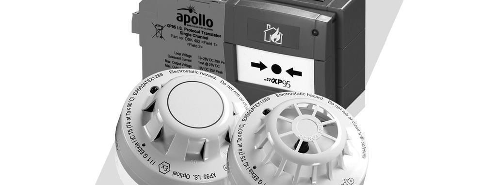
5 3 XP95 I.S. Ionisation Smoke Detector The sensing part of the detector consists of two chambers an open, outer chamber and a reference chamber within. Mounted in the reference chamber is a low-activity radioactive foil of Americium 241 which enables current to flow across the inner and outer chambers when the detector is powered up. Item No Part No Description APO XP95 I.S. Ionisation Smoke Detector As smoke enters the detector, it causes a reduction of the current flow in the outer chamber and hence an increase in the voltage measured at the junction between the two chambers. This analogue voltage signal is converted to a digital signal by the electronic circuitry and transmitted to the control panel on interrogation. The micro-processor in the control equipment then compares the signal with stored data and initiates a prealarm or fire alarm as smoke density increases. When a fire condition exists, the panel instructs the detector to switch on its indicator LED. Full details of the principles of operation and electrical description are published in the XP95 Engineering Product Guide. Information on the performance of XP95 in adverse environmental conditions is also given in this guide. XP95 I.S. detectors have the same operating characteristics as the standard versions. 3.1 Safety Note In the United Kingdom, ionisation smoke detectors are subject to the requirements of the Radioactive Substances Act 1993 and to the Ionising Radiations Regulations 1999 made under the provisions of the Health and Safety at Work Act The detectors, independently tested by the National Radiological Protection Board (NRPB), conform to all the requirements specified in the Recommendations for ionisation smoke detectors in implementation of radiation standards published by the Nuclear Energy Agency of the Organisation for Economic Co-operation and Development (OECD) Technical Data Specifications are typical and given at 23 C and 50% relative humidity unless otherwise specified. Technical Data for the I.S. ionisation detector is identical to that for the standard version, except for the information given below: XP95 I.S. Ionisation Smoke Detector Base Item No Base Part No Supply Wiring Two wire supply, polarity sensitive. Terminal Functions L1: positive supply. L2: negative supply and remote LED negative. +R: remote LED positive. Notes: 1. I.S. detectors are polarity sensitive. Notes: 2.Refer Remote LED Connection section for correct wiring details. Supply Voltage Volts dc. Quiescent Current 300µA Operating Temperature 20 C to +40 C (T5). 20 C to +60 C (T4). Remote LED Current 1mA (internally limited) BASEEFA Certificate No BAS02ATEX1289 Classification E Ex ia IIC T5 (T4 at Ta 60 C) 3
6 There is no limit to the number of ionisation smoke detectors which may be installed in any fire protection system. Storage regulations depend on local standards and legislation, but, in the UK, up to 500 detectors may be stored in any premises, although there are stipulations on storage facilities if more than 100 ionisation detectors are stored in one building. At the end of their recommended working life of ten years, ionisation smoke detectors should be returned to the manufacturer for safe disposal or disposed of in an otherwise locally approved and environmentally safe manner. Please refer MAN3046 for information regarding detector cleaning, maintenance & testing. Guidance on storage and handling can be requested from: Radioactive Substances Regulation Function Environment Agency Rio House, Waterside Drive Aztec West, Almondsbury Bristol BS32 4UD. Outside the UK, please contact the relevant national agency. 4

7 4 XP95 I.S. Optical Smoke Detector Optical smoke detectors incorporate a pulsing LED located in a labyrinth within the housing of the detector. The labyrinth is designed to exclude light from any external source. At an angle to the LED is a photo-diode which, in clear air conditions, does not receive light directly from the LED. The detector transmits a clear air signal to the control panel. When smoke enters the labyrinth, light is scattered onto the photo-diode and the signal to the panel increases. Item No Part No Description APO XP95 I.S. Optical Smoke Detector The signal is processed by the electronic circuitry and transmitted to the control equipment in exactly the same way as in the case of the ionisation smoke detector. Full details of the principles of operation and the electrical description are published in the XP95 Engineering Product Guide. XP95 I.S. detectors have the same operating characteristics as the standard versions. 4.1 Technical Data Specifications are typical and given at 23 C and 50% relative humidity unless otherwise specified. Technical Data for the I.S. optical detector is identical to that for the standard version, except for the information below. XP95 I.S. Optical Smoke Detector Base Item No Base Part No Supply Wiring Two wire supply, polarity sensitive. Terminal Functions L1: positive supply. L2: negative supply and remote LED negative. +R: remote LED positive. Notes: 1. I.S. detectors are polarity sensitive. Notes: 2.Refer Remote LED Connection section for correct wiring details. Supply Voltage Volts dc. Quiescent Current 340µA Operating Temperature 20 C to +40 C (T5). 20 C to +60 C (T4). Remote LED Current 1mA (internally limited) BASEEFA Certificate No BAS02ATEX1289 Classification E Ex ia IIC T5 (T4 at Ta 60 C) 5
8 5 XP95 I.S. Heat Detector The XP95 I.S heat detector is distinguishable from XP95 I.S smoke detectors by its low air-flow resistance case which allows good contact between the sensing thermistor and the surrounding air. Item No Part No Description APO XP95 I.S. Heat Smoke Detector The device monitors temperature by using a single thermistor network which provides a voltage output proportional to the external air temperature. The voltage signal is processed and transmitted to the control equipment in the same way as in the case of the ionisation smoke detector. Full details of the principles of operation and the electrical description are published in the XP95 Engineering Product Guide. XP95 I.S. detectors have the same operating characteristics as the standard versions. 5.1 Technical Data Specifications are typical and given at 23 C and 50% relative humidity unless otherwise specified. Technical data for the I.S. heat detector is identical to that for the standard version, except for the information below. XP95 I.S. Heat Smoke Detector Base Item No Base Part No Supply Wiring Two wire supply, polarity sensitive. Terminal Functions L1: positive supply. L2: negative supply and remote LED negative. +R: remote LED positive. Notes: 1. I.S. detectors are polarity sensitive. Notes: 2.Refer Remote LED Connection section for correct wiring details. Supply Voltage Volts dc. Quiescent Current 300µA Operating Temperature 20 C to +40 C (T5). 20 C to +60 C (T4). Remote LED Current 1mA (internally limited) BASEEFA Certificate No BAS02ATEX1289 Classification E Ex ia IIC T5 (T4 at Ta 60 C) 6 XP95 I.S. Detector Base The base for the intrinsically safe range is not identical with that for the standard range. This ensures that standard detectors cannot inadvertently be fitted to an intrinsically safe system. For full details of the XP95 address mechanism refer to the XP95 Engineering Product Guide. Item No Part No Description XP95 I.S. Detector Base 6
9 7 XP95 I.S. Manual Call Point When activated, the intrinsically safe call point not only interrupts the polling cycle to indicate to the control panel that it has been operated, but also reports its address. Thus an alarm and its location can be reported in less than 0.2 seconds. Item No Part No Description APO XP95 I.S. Manual Call Point Full details of the principles of operation and the electrical description are published in the XP95 Engineering Product Guide. XP95 I.S. manual call points have the same operating characteristics as the standard versions. They are available in two types of housing and in a number of versions. The standard call point is based on the KAC waterproof model and is a red, break-glass call point. This model is also available in other colours and a protective lift-up flap is available. Table 4 gives full details of KAC based versions and part numbers. Item No Part No Colour IP Rating Red Yellow* Blue* 65 Table 4: KAC based manual call points *Does not have LPCB or CPD approval, or comply with EN54-11 For heavy-duty applications a robust manual call point based on a model by MEDC is available. This model is made of glass-reinforced polyester and may be ordered as a break-glass or push-button call point and in a variety of colours. Break-glass models may be supplied with or without a stainlesssteel protective flap. Table 5 gives part numbers and full details of MEDCbased call points. Part No APO Description XP95 I.S. MEDC Manual Call MEDC-based break-glass units have two M20 cable entries on the bottom face of the back-box. Push button units have one M20 cable entry on the bottom face and one on the top face. Other cable entry configurations can be provided to special order. Part No Colour Type IP Rating Red Break Glass Yellow Break Glass Blue Break Glass Black/Yellow stripes Break Glass Red Break Glass with flap Yellow Break Glass with flap Blue Break Glass with flap Black/Yellow stripes Break Glass with flap Red Push-button Yellow Push-button Blue Push-button Black/Yellow stripes Push-button 66 Table 5: MEDC - based Manual Call Points 7
10 7.1 Technical Data Specifications are typical and given at 23 C and 50% relative humidity unless otherwise specified. Technical data for the I.S. manual call point is identical to that for the standard version, except for the information below. XP95 I.S. Manual Call Points Supply Wiring Two wire supply, polarity sensitive. Terminal Functions L1: positive supply L2: negative supply Note: I.S. devices are polarity sensitive Supply Voltage Volts dc. Quiescent Current 230µA Operating Temperature 20 C to +40 C (T5). 20 C to +60 C (T4). Remote LED Current 1mA (internally limited) BASEEFA Certificate No BAS02ATEX1290 Classification E Ex ia IIC T5 (T4 at Ta 60 C) Dimensions & Weight Part No (KAC-based MCP): 124mm x 124mm x 60mm. Weight: approx. 400g Part No (MEDC-based MCP): 126mm x 120mm x 67mm (126mm x 120mm x 114mm push button call point). Weight: approx. 1.20kg 8
11 8 XP95 Intrinsically Safe Communications Protocol The standard XP95 communications protocol is designed to be very robust and to give the maximum flexibility to designers of loop driver circuits. The current and voltage levels used are chosen to be well above noise levels and to operate in adverse conditions with the minimum of errors. The maximum voltage and current levels used are, however, outside the limits of intrinsically safe systems and it has been necessary to apply lower limiting values for both current and voltage in the I.S. range. The voltage limitation arises because of the need for safety barriers. The barriers used with I.S. detectors are rated at 28 volts, the highest rating that is commercially available. These are used to limit the voltage inside the hazardous area to a (practical) maximum of about 26V DC. Although this is within the standard XP95 protocol specification, it is lower than that provided by most loop drivers. The safety barrier is also responsible for the current limitation because the 28V barriers have a series resistance of at least 300 ohms. This resistance results in unacceptable voltage drops if the normal 20mA current pulses are used. It has therefore been necessary to reduce the amplitude of the current pulses to 10mA. The differences between the standard protocol and the intrinsically safe are summarised in Table 6. Parameter XP95 Standard XP95 I.S. DC Input Voltage 17-29V DC 14 22V DC Pulse Voltage Peak to Peak 5 9V 5 9V DC + Pulse Voltage 37V max 26.5V max Current Pulse Amplitude 18 22mA 9 11mA Input Voltage Polarity Polarity insensitive L1 positive L2 negative Table 6: Protocol Variance Data 8.1 XP95 Protocol Translator In order to enable the use of standard control and indicating equipment in intrinsically safe systems, a device to translate voltage levels from any loop driver operating within the XP95 limits to levels compatible with the I.S. detectors is required. The translator also boosts the current pulses returned by the I.S. detectors from 10mA to 20mA, thereby ensuring compatibility with standard loop driver thresholds. Item No Part No Description APO XP95 Single Channel Protocol Translator APO XP95 Dual Channel Protocol Translator The translator is a loop-powered device which draws a low quiescent current and is therefore transparent to both the loop driver and the I.S. detectors. Since the translator is used within the safe area, i.e., before the safety barrier, no certification is necessary. The translator falls within the generic description Safe Area Apparatus on the certified system diagram. The translator is housed in a moulded plastic enclosure which can be either clipped onto a standard 35mm DIN rail (DIN 46277) or panel mounted by using pull-out latches in the base. The translator is available in single-channel or dual-channel versions. Each channel should only be connected to a single intrinsically safe circuit through an appropriate safety barrier. Each channel is thus capable of supplying up to twenty XP95 I.S. devices. A block schematic of the dual-channel translator, showing terminal designations, is given in Fig 1. In the single-channel unit the Channel 2 circuit is not fitted and terminal 12 is not used. The input to the unit consists of the normal XP95 signal, that is a d.c. voltage on which is superimposed the protocol pulses. 9
12 8.2 Translator Operation The translator first regulates the d.c. level to 18V. The incoming protocol pulses are then sensed and regenerated and shaped with a fixed amplitude of 6V, and superimposed on the 18V d.c. output level. The 10mA current pulses drawn by the I.S. devices are detected by the current pulse sensor whose output is used to switch the 10mA current sink across the input terminals synchronously with the device current pulse. The current boosting mechanism is inhibited during the protocol pulses so that when low resistance loads are connected to the translator output the protocol current is not boosted. A separate current limiting circuit is incorporated in each channel which limits the maximum (peak) output current to 35mA. This level of current will ensure that safety barrier fuses are not blown in the event of a short-circuit on the barrier output. When the dual-channel unit is used it must be remembered that the loop input, and the negative side of the output, is common to the two channels. It is not possible, therefore, to connect the two channels to different loops. Although the two channels have a common input, their outputs are individually current-limited to 35mA (nominal). Hence, a short-circuit on one channel will cause the loop current to increase by 35mA and as long as the panel is able to support this load the second channel will continue to operate normally. 8.3 Technical Data Figure 1: Schematic Diagram XP95 Protocol Translator Specifications are typical and given at 23 C and 50% relative humidity unless otherwise specified. Supply Wiring Supply Voltage Modulation Voltage at Translator Input Current (no load condition) Output Voltage (to barrier) Output Modulation Voltage (no barrier) Output Current (to barrier) Input Pulse Current (from barrier) Output Pulse Current (drawn from loop) Operating Temperature Humidity (no condensation) Dimensions Weight XP95 Protocol Translator Two wire supply, polarity sensitive 19 to 28 Volts 5 to 9 Volts peak to peak 2mA max (dual channel) 1mA (single channel) 16.5 to 19 Volts 5 to 6.5 Volts 0.2 to 30mA 8 to 12mA. 17 to 23mA. 20 C to +60 C. 10 to 95% relative humidity x 110 x 20mm Approx 100g 10
13 9 System Design The design of an intrinsically safe fire detection system should only be undertaken by engineers familiar with codes of practice for detection systems and hazardous area electrical systems. In the UK the relevant standards are BS5839: Part 1 and BS EN :2003 respectively. The fire detection performance of the XP95 I.S. range is the same as that of its standard counterparts. Performance information given in the XP95 Engineering Product Guide is therefore applicable to the I.S. range. The BASEEFA certification of the I.S. devices covers their characteristics as components of an intrinsically safe system and indicates that they can be used with a margin of safety in such systems. The precise way in which the system can be connected and configured is covered by an additional, system certification. The System Diagram, Z20982, shown at the back of this guide, details cable parameters and permissible configurations of detectors, manual call points and safety barriers which are certified by BASEEFA. Any user wishing to install a system outside the parameters given on this system diagram cannot make use of the device certification and should seek independent certification from a competent certification body. The BASEEFA system certificate number is Ex94C2444. Any system installed within the parameters specified in Z20982 should be marked in accordance with BS EN :2004. The marking should include at least XP95 I.S. Fire Detection System, BASEEFA No Ex94C2444 SYST. In safe area (standard) applications it will be normal practice to connect the wiring as a loop, with both ends terminated at the control panel. In the event of an open-circuit fault it is then possible to drive both ends simultaneously. In a hazardous area it is not possible to use a loop configuration because the potential to feed power from each end of the loop would double the available energy in the hazardous area and contravene the energy limitations of the I.S. certification. All XP95 I.S. circuits must therefore be connected as spurs from the safe area loop or as radial connections from the control panel. It is recommended, for the highest system integrity, that each I.S. circuit be restricted to a single zone and that the connection from the safe area loop to the I.S. spur be protected on each side by XP95 isolators. The DIN-rail dual isolator ( ) is particularly suited to this application. This configuration, shown in Fig 3, will conform fully with the requirements of BS5839:Part 1 and with the European Guidelines DD CEN/TS 54-14:2004 since a single wiring fault will result in the loss of only one zone of detection. In certain circumstances it may be possible for the simpler configuration, shown in Fig 4, to be used. This arrangement may include single or dual-channel translators, housed, together with the critical wiring, in a robust mechanical enclosure. Figure 2: Schematic Wiring Diagram of XP95 I.S. Circuit 11
14 Figure 3: Schematic Wiring Diagram of XP95 I.S. circuit using Dual Channel Protocol Translator Figure 4: Detail of Schematic Diagram of I.S. Zone 12
15 10 Types of Safety Barriers The certified system configurations allow for three types of safety barrier, each of which has its own advantages and disadvantages. A brief outline of their characteristics is given below Single Channel 28V/300Ω Barrier This is the most basic type of barrier and therefore the lowest in cost. Being passive devices, they also impose the minimum of restrictions on the operation of the fire detectors. Thus, single channel barriers are available either as positive or negative polarity where the polarity refers to the polarity of the applied voltage relative to earth. The significance of this is that one side of the barrier must be connected to a high-integrity (safety) earth. Although this earth connection has no effect on the operation of the XP95 I.S. devices and is not needed for their correct operation, it may not be acceptable to the operation of the control and indicating equipment. This is particularly true if the control equipment incorporates earth leakage monitoring and even without this feature the earthing of the loop may cause unwanted cross-talk between loops. If the earth connection is not acceptable then the A.C. or isolating barriers should be used Star-connected A.C. Barrier A.C. barriers are also passive devices and must still be connected to a high-integrity safety earth. However, they are designed to allow either positive or negative voltages with respect to earth and under normal conditions provide a connection to earth via a reverse-biased diode, rather than directly. The disadvantage of this type of barrier is that the end-to-end resistance is nominally 1200 ohms compared with the 300 ohms of the single channel type. This high resistance results in an extra voltage drop in the circuit. This type of barrier is not recommended for general use Galvanically Isolated Barrier Galvanically isolated barriers (also known as transformer isolated barriers) differ from conventional shunt zener barriers in that they provide electrical isolation between the input (safe area) and the output (hazardous area). This is achieved by the use of a D.C./D.C. converter on the input side which is connected to the hazardous area through a voltage-and power-limiting resistor/zener combination similar to a conventional barrier. The galvanic isolation technique means that the circuit does not need a high integrity (safety) earth and that the intrinsically safe circuit is fully floating. Earth leakage problems for control and indicating equipment are therefore eliminated if this type of interface is used. Note: Although the circuit does not require a high-integrity earth, it is permissible to earth either side of the hazardous area circuit if required by other system considerations. Although galvanically isolated barriers are widely used with conventional fire detectors the pulse response of standard products has been too slow to allow their use in analogue addressable systems. Pepperl + Fuchs have developed a special galvanically isolated barrier which freely transmits the XP95 protocol pulses without introducing severe voltage drops. This interface is available as single or dual channel versions and is recommended for any application in which direct earth connections are not acceptable. The Pepperl + Fuchs type numbers are KFDO-CS-Ex1.54 and KFDO-CS-Ex2.54 for the single and dual channel devices respectively. Both versions are BASEEFA certified under certificate number BAS00ATEX7087. (The KFDO- types have replaced the earlier KHDOtypes.) The galvanically isolated barrier is a two-wire device which does not need an external power supply. Current drawn from the XP95 loop by the barrier itself is less than 2mA when loaded as specified by the manufacturer. The housing is a rail-mounted type identical to that used for the protocol translator. 13
16 10.4 Approved Safety Barriers The system certification includes a generic specification for barriers, two additional, individually approved barriers and two transformer isolated current repeaters (ie, barriers). The generic specification is: any shunt zener diode safety barrier certified by BASEEFA or any EEC approved certification body to E Ex ia IIC having the following or lower output parameters: Uz = 28V I max:out = 93.3mA W max:out = 0.67W In any safety barrier used the output current must be limited by a resistor R such that I max:out = Uz R A number of single-channel barriers meet this specification and examples are given below: Supplier Type Supplier Type Polarity Mounting Pepperl & Fuchs Ltd Z728 +ve DIN-rail Z828 -ve DIN-rail Z428/Ex +ve DIN-rail/surface Z528/Ex -ve DIN-rail/surface Measurement Technology Ltd MTL728+ +ve Busbar MTL ve DIN-rail MTL ve DIN-rail Weidmuller (Klippon) S951 +ve (Cat No ) DIN-rail/surface +ve (Cat No ) E951APOS +ve DIN-rail/surface E951ANEG -ve DIN-rail/surface Two individually approved star barriers are: Table 7: 28V/300Ω single channel safety barriers Pepperl & Fuchs Z978 Star connected shunt zener disode safety barrier, 28V/600Ω, dual channel. BASEEFA certificate No Ex 93C2412, BAS01ATEX7005 Measurement Technology Ltd. MTL 778 Star connected shunt zener diode safety barrier, 28V/600V. BASEEFA certificate no. Ex , BAS01ATEX Safety Earth Single channel and star connected A.C. safety barriers must be connected to a high integrity earth by at least one and preferably two copper cables, each of cross sectional area of 4mm2 or greater. The connection must be such that the impedance from the connection point to the main power system earth is less than one ohm. Intrinsically safe circuits in the hazardous area should be insulated from earth and must be capable of withstanding a 500V RMS A.C. test voltage for at least one minute. When using armoured or copper sheathed cables, the armour or sheath is normally isolated from the safe area busbar. 14
17 11 Wiring and Cabling Types It is not permitted to connect more than one circuit in the hazardous area to any one safety barrier and that circuit may not be connected to any other electrical circuit. Both separate and twin cables may be used. A pair contained in a type A or B multicore cable (as defined in clause of BS EN :2004) may also be used, provided that the peak voltage of any circuit contained within the multicore does not exceed 60V. The capacitance and either the inductance or the inductance to resistance (L/R) ratio of the hazardous area cables must not exceed the parameters specified in Table 8. The reason for this is that energy can be stored in a cable and it is necessary to use cable in which energy stored is insufficient to ignite an explosive atmosphere. To calculate the total capacitance or inductance for the length of cables in the hazardous area, refer to Table 9, which gives typical per kilometer capacitance and inductance for commonly used cables. (Note: All XP95 I.S. devices have zero equivalent capacitance and inductance.) Group Capacitance µf Inductance mh L/R Ratio µh/ohm IIC IIB IIA Table 8: Limits for Energy Stored in Cables Cable Type Core Size mm² MICC Pyrotenax light duty MICC Pyrotenax heavy duty Pirelli FP200 PVC sheathed and insulated to BS 6004 Conductance resistance ohm/km/core Inductance mh/km Capacitance µf/km core to core core to sheath Sheath Resistance ohm/km All All Table 9: Examples of electrical characteristics of cable commonly used in fore protection systems 11.1 Maximum Loading of I.S. Circuit Because of the finite resistance of the safety barrier, there will be a limit to the current drain which can be tolerated before the voltages on the circuit fall outside the specified limits for XP95 I.S. devices. Two components of the current drain must be considered, namely the standing current of the devices by themselves and the maximum drain caused by alarm LEDs being illuminated. The standing current of the devices can be calculated by taking the sum of the individual device currents on the circuit, as given in the section Technical data for each product. The maximum number of LEDs that can be illuminated simultaneously should ideally be limited by the panel software. Because the LED load is often the limiting factor in determining the voltage drop, the later versions of the XP95 I.S detectors are fitted with high efficiency LEDs. This has allowed a reduction from 2mA to 1mA in the LED current. It is important when fitting remote LEDs that high efficiency types are used. 15
18 Table 10 shows the maximum device standing current which can be supported for varying numbers of LEDs illuminated. Maximum number of LEDs illuminated Max (total) device load (ma) Table 10: Maximum Loading (28V/300Ω single channel barrier) 11.2 Installation It is important that the XP95 I.S. detectors are installed in such a way that all terminals and connections are protected to at least IP20 when the detector is in the base. Special care must be taken with the rear of the mounting base where live metal parts (rivets) may be accessible. Flush mounting of the base on a flat surface will provide the required degree of protection. If the base is mounted on a conduit box (e.g. BESA box or similar) whose diameter is less than 85mm then the base should be fitted with a Series 60/XP95 Backplate (part number ). Use of the backplate will prevent access to the metal parts and will also protect the rear of the base from water ingress. The conduit box, part no , is also acceptable for mounting I.S. bases together with a range of deckhead mounting boxes. Note that the earth terminal in the base is provided for convenience where continuity of a cable sheath or similar is required. It is not necessary for the correct operation of the detector nor is it provided as a termination point for a safety earth Remote LED Connection A drive point is provided on each of the XP95 I.S. detectors for a remote LED indicator. For connection details see Fig. 4. The indicator must be a standard high-efficiency red LED and does not require a series limiting resistor since current is limited within the detector to approximately 1mA. The remote LED cannot, as in the standard XP95 range, be controlled independently from the integral LED since it is effectively connected in series with the integral LED. The benefit of this configuration is that illumination of the remote LED does not increase the current drawn from the loop. The system certification allows for the use of any LED indicator having a surface area between 20mm2 and 10cm2 which covers all commonly used case styles from T1 (3mm) upwards but would exclude some miniature and surface mounted types. Additional requirements of the certification are that the LED and its terminations must be afforded a degree of protection of at least IP20 and must be segregated from other circuits and conductors as defined in BS EN :2003. The MiniDisc Remote Indicator ( ) is suitable. 16
19 12 Servicing Servicing of I.S. fire detectors may be carried out only by a BASEEFA authorised body. In practical terms this means that XP95 I.S. fire detectors may be serviced only by the manufacturer at its factory. Servicing of the fire protection system should be carried out as recommended by the code of practice BS 5839: Part 1 or other local regulations in force. For more information on servicing detectors, please refer to MAN3046, Detector Cleaning, Maintenance and Functional Testing. 13 Approvals XP95 I.S. detectors have been approved by LPCB to EN54 and the XP95 I.S. manual call point, part no , is LPCB approved to BS5839 : Part 2. These products have also been approved for marine use by the following bodies: American Bureau of Shipping Bureau Veritas Det Norske Veritas Germanisher Lloyd Lloyds Register of Shipping Maritime and Coastguard Agency Details of approvals held are available on request. The product Certification Technical Files for the XP95 IS range are held by BASEEFA in accordance with the requirements of the ATEX Directive 94/9/EC. All detectors and manual call points are marked. 14 Acknowledgement The XP95 range of detectors and products are manufactured for Ampac by Apollo Fire Detectors Ltd. 17
20 15 XP95 I.S. System Drawing Note: P + F Z378/Ex has been superseded by P + F Z978 18
21 19
22 UNCONTROLLED DOCUMENT NOTE: Due to AMPAC s commitment to continuous improvement specifications may change without notice. 20
Intrinsically Safe Flame Detector Installation Guide
 This document is IS Installation Guide/00/Issue 3 Intrinsically Safe Installation Guide General This Installation Guide gives information on the intrinsically safe (I.S.) version of the flame detectors
Orbis IS Product Guide MAN 3041
 Orbis IS Product Guide MAN 3041 TABLE OF CONTENTS Page No. 1 Introduction to Intrinsic Safety... 2 2 Range of Products... 3 3 Features of Orbis IS... 3 4 Choosing a Detector: Q & A... 3 5 Orbis IS Optical
Series 65 Product Guide MAN 3036
 Series 65 Product Guide MAN 3036 TABLE OF CONTENTS Page No. 1 Ionisation Smoke Detector... 1 1.1 Operating Principles:... 1 1.2 Product Codes... 2 1.3 Integrating Version:... 2 1.4 Options:... 2 1.5 Safety
SERIES 65 ENGINEERING PRODUCT GUIDE
 SERIES 65 ENGINEERING PRODUCT GUIDE Wide voltage conventional detectors Series 65 incorporates well-proven sensing technologies, including an IC based on that used in XP95 analogue addressable detectors.
SERIES 65 ENGINEERING PRODUCT GUIDE
 SERIES 65 ENGINEERING PRODUCT GUIDE Wide Voltage Conventional Detectors Series 65 incorporates well-proven sensing technologies, including an Integrated Circuit based on that used in XP95 analogue addressable
INSTRUCTION MANUAL IS-mB1 Minialite Intrinsically Safe Round LED Beacon
 INSTRUCTION MANUAL Minialite Intrinsically Safe Round LED This instruction sheet describes installations which conform to EN60079:Part14:2008 Electrical Installation in Hazardous Areas. When designing
Intrinsically Safe Solutions
 Intrinsically Safe Solutions INSTALLATION MANUAL 04/12/14 Rev D DOC-01-029 Documentation Feedback Your feedback helps us keep our documentation up to date and accurate. If you have any comments or suggestions
DB5 Intrinsically Safe Sounder Type DB-5
 Operating Instructions RTK Instruments Limited DB5 Intrinsically Safe Sounder Type DB-5 Description The DB5 Sounder is a strong, lightweight warning sounder, CENELEC certified to Ex II 1G EExia IIC T4
4) Intrinsic Safety Certification
 Intrinsic Safety Certification") INSTRUCTION MANUAL Minialert Intrinsically Safe Round Combined Unit Section Volume Control Tone Generator S2 S3 Tone Selection Switches Fig 1 Simplified block diagram The combined unit is CE marked for
INSTRUCTION MANUAL Minialert Intrinsically Safe Round Combined Unit Section Volume Control Tone Generator S2 S3 Tone Selection Switches Fig 1 Simplified block diagram The combined unit is CE marked for
XP95 ENGINEERING PRODUCT GUIDE
 XP95 ENGINEERING PRODUCT GUIDE Ionisation Smoke Detector Optical Smoke Detector Temperature Detector Multisensor Detector Manual Call Point Isolating Base The XP95 range of intelligent fire detectors is
Optical Smoke Detector Heat Detector Manual Call Point Output Unit Isolator
 TECHNICAL GUIDE Optical Smoke Detector Heat Detector Manual Call Point Output Unit Isolator The XPlorer Range XPlorer is a new range of analogue addressable detectors and interfaces developed for all who
Fire Alarm System Accessories
 Approved by APPROVED Fire Alarm System Accessories FM Approved* Intrinsically Safe Devices Single and Dual Channel Isolated Barrier Modules Features Single or dual channel intrinsically safe, transformer
S200Plus Triple Infra Red Flame Detector Triple Waveband Infra-Red Flame Detection
 DATASHEET S200Plus Triple Infra Red Flame Detector Triple Waveband Infra-Red Flame Detection Features: Unrivalled black body rejection over a wide range of source temperatures Triple waveband infra-red
MINERVA S200Plus. Fire Detection. Triple Waveband Infra-Red Flame Detection. Features: Minerva S200PLUS
 MINERVA S200Plus Triple Waveband Infra-Red Flame Detection Features: Unrivalled black body rejection over a wide range of source temperatures Triple waveband infra-red solar blind flame detection for optimum
A GUIDE TO EUROPEAN (EEC) CERTIFICATION FOR ELECTRICAL EQUIPMENT IN HAZARDOUS AREAS
 CERTIFICATION FOR ELECTRICAL EQUIPMENT IN HAZARDOUS AREAS") A GUIDE TO EUROPEAN (EEC) CERTIFICATION FOR ELECTRICAL EQUIPMENT IN HAZARDOUS AREAS For a print friendly page click here INTRODUCTION Hazardous areas are those in which there exists a risk of explosion
A GUIDE TO EUROPEAN (EEC) CERTIFICATION FOR ELECTRICAL EQUIPMENT IN HAZARDOUS AREAS For a print friendly page click here INTRODUCTION Hazardous areas are those in which there exists a risk of explosion
The R. STAHL Technology Group Worldwide Success with Competence and Customer Support
 The R. STAHL Technology Group Worldwide Success with Competence and Customer Support The entrepreneurial basis of the R. STAHL Technology Group follows a long tradition. The product range is aimed at specialised
Engineering Product Guide Ionisation Smoke Detectors Optical Smoke Detectors Resettable Heat Detectors
 Engineering Product Guide Ionisation Smoke Detectors Optical Smoke Detectors Resettable Heat Detectors SERIES 60 CONVENTIONAL FIRE DETECTORS Series 60 is a range of conventional fi re detectors, designed
ED820-24V MODEL INSTRUCTION MANUAL. fire DETECTOR
 ED820 24V MODEL fire DETECTOR INSTRUCTION MANUAL Address: Enigma House, Enigma Business Park, Malvern, Worcestershire, WR14 1GD Tel: 44 (0)1684 891500 Fax: 44 (0)1684 891600 Email: sales@electronicdevices.co.uk
IECEx Certificate of Conformity
 INTERNATIONAL ELECTROTECHNICAL COMMISSION IEC Certification Scheme for Explosive Atmospheres for rules and details of the IECEx Scheme visit www.iecex.com Certificate No. : Status: Date of Issue: Applicant:
Fire Alarm System Accessories
 UL, ULC Approved* Fire Alarm System Accessories Intrinsically Safe Devices Single and Dual Channel Isolated Barrier Modules Features Single or dual channel intrinsically safe, transformer isolated barrier
Universal Tank Alarm Type Installation, Operation & Maintenance
 Universal Tank Alarm Type 14400 Installation, Operation & Maintenance Universal Tank Alarm Type 14400 Contents Declaration of Conformity 3 IMPORTANT 3 General Description 4 General Operation 4 Installation
Hazardous Areas - EXPLOSIONPROOF SOLENOIDS
 Hazardous Areas - EXPLOSIONPROOF SOLENOIDS SOME HISTORY The classification of hazardous areas into zones established the level of protection required for electrical equipment installed in explosive gas
1. GENERAL TECHNICAL INFORMATION
 1. GENERAL TECHNICAL INFORMATION 1.1 EXPLOSIVE ATMOSPHERES: Every time that dangerous quantities and concentration of flammable gas, vapors mixture or dust clouds exists, risk of explosions may arise.
Page 1 Copyright by the Fieldbus Foundation All rights reserved.
 Page 1 Copyright by the Fieldbus Foundation 1996-2004.. FOUNDATION Fieldbus Application Guide 31,25 kbit/s Intrinsically Safe Systems AG-163 Revision 2.0 This application guide has been prepared to aid
VERSAFLOW VORTEX Supplementary instructions
 VERSAFLOW VORTEX Supplementary instructions Vortex flowmeter Equipment category II 2G CONTENTS VERSAFLOW VORTEX 1 Safety instructions 3 1.1 General notes... 3 1.2 EC conformity... 3 1.3 Approval according
0 A EIS Intrinsically-Safe Plug-in Intelligent Photoelectronic Smoke Detector INSTALLATION AND MAINTENANCE INSTRUCTIONS
 INSTALLATION AND MAINTENANCE INSTRUCTIONS 2251EIS Intrinsically-Safe Plug-in Intelligent Photoelectronic Smoke Detector A Division of Pittway 3825 Ohio Avenue, St. Charles, Illinois 60174 1-800-SENSOR2,
XP95 Product Guide MAN 3037
 XP95 Product Guide MAN 3037 TABLE OF CONTENTS Page No. 1 Introduction... 1 2 Application of XP95 Detectors... 1 3 Addressing and Communications... 1 4 Approvals & Regulatory Compliance... 2 5 Protocol
ENGINEERING PRODUCT GUIDE
 RDM ENGINEERING PRODUCT GUIDE Radio linked detectors and interfaces CONTENTS Radio Detector Monitoring 1 RDM Ionisation Smoke Detector RDM Radio-linked detectors with base and interfaces Operating Principles
INSTRUCTION & SERVICE MANUAL
 INSTRUCTION & SERVICE MANUAL D2xC1 ALARM HORN AND STROBE For Use In Hazardous Locations 3) Ratings and Markings 3.1 ATEX / IECEx certification The D2xC1 Alarm Horn and Strobe complies with the following
INSTRUCTION MANUAL (ATEX/IECEx/SIL2) BExBG05D-SIL Flameproof Xenon SIL 2 Beacons For use in Flammable Gas and Dust Atmospheres
 BExBG05D-SIL Flameproof Xenon SIL 2 Beacons For use in Flammable Gas and Dust Atmospheres") INSTRUCTION MANUAL (ATEX/IECEx/SIL2) BExBG05D-SIL Flameproof Xenon SIL 2 Beacons For use in Flammable Gas and Dust Atmospheres 1) Introduction The BExBG05D-SIL is a flameproof beacon which is certified
INSTRUCTION MANUAL (ATEX/IECEx/SIL2) BExBG05D-SIL Flameproof Xenon SIL 2 Beacons For use in Flammable Gas and Dust Atmospheres 1) Introduction The BExBG05D-SIL is a flameproof beacon which is certified
DUR 40Ex Intrinsically Safe SMOKE DETECTOR
 DUR 40Ex Intrinsically Safe SMOKE DETECTOR Installation and Maintenance Manual IK E317 001GB IB Issue 2 IK E317 001GB The Universal Optical Smoke Detector DUR 40Ex covered by the present manual, complies
A guide to the use of electrical equipment in potentially explosive atmospheres To view this document in PDF format click here.
 A guide to the use of electrical equipment in potentially explosive atmospheres To view this document in PDF format click here Introduction Potentially Explosive Atmospheres exist where there is a risk
INSTRUCTION MANUAL (ATEX / IECEx)
") INSTRUCTION MANUAL (ATEX / IECEx) BExS110D and BExS110D-R Sounder For use in Flammable Gas and Dust Atmospheres BExS110D BExS110D-R 1) Warnings DO NOT OPEN WHEN AN EXPLOSIVE ATMOSPHERE IS PRESENT DO NOT
INSTRUCTION MANUAL (ATEX / IECEx) BExS110D and BExS110D-R Sounder For use in Flammable Gas and Dust Atmospheres BExS110D BExS110D-R 1) Warnings DO NOT OPEN WHEN AN EXPLOSIVE ATMOSPHERE IS PRESENT DO NOT
Technical Data. General specifications Switching element function Rated operating distance s n 4 mm
 0102 Model Number Features 4 mm non-flush Accessories BF 12 Mounting flange, 12 mm Technical Data specifications Switching element function NAMUR, NO Rated operating distance s n 4 mm Installation non-flush
Analogue addressable devices
 Apollo XP95 Analogue addressable devices from Channel Safety Systems Apollo XP95 Analogue addressable devices The XP95 range of analogue addressable fire detectors is advanced in design, improved in performance
E2S Datasheet v10a. The IS-mA1 is suitable for all intrinsically safe signalling applications including fire, security and process control.
 E2S Datasheet 1.2.1 v10a ISmA1 ISminialarm The ISmA1 is a compact, 100dB(A) alarm sounder. Approvals include ATEX, IECEx and GOSTR for Zone 0 applications and FM approval for Class I Division 1 and Class
BA334D Intrinsically safe Externally powered pulse input field mounting rate totaliser Issue 13
 TR Automatyka Sp. z o. o. Tel. (+48 022) 886 10 16 www.trautomatyka.pl ul. Lechicka 14 ; 02-156 Warszawa Fax. (+48 022) 846 50 37 biuro@trautomatyka.pl BA334D Intrinsically safe Externally powered pulse
MR300 OPTICAL SMOKE DETECTOR RANGE PRODUCT APPLICATION & DESIGN INFORMATION
 DOCUMENT CONTROL NUMBER / MR300 OPTICAL SMOKE DETECTOR RANGE PRODUCT APPLICATION & DESIGN INFORMATION 1. INTRODUCTION The MR300 range of optical smoke detectors forms part of the M300 series of plug-in
Additional Operating Instructions SITRANS F. Vortex flowmeters. SITRANS FX330 Ex-i.
 Additional Operating Instructions SITRANS F Vortex flowmeters Ex-i Edition 09/2018 CONTENTS 1 Safety instructions 3 1.1 General notes... 3 1.2 EU conformity... 3 1.3 Approval according to the IECEx scheme...
OilSET Installation and Operating Instructions. Oil Separator Alarm Device with SET/DM3AL sensor
 Labkotec UK Ltd Adminicle House 1 Lumb Lane Audenshaw Manchester M34 5WH GREAT BRITAIN Tel: 0844 3350 477 Fax: 0161 4281 179 E-mail: info@labkotec.co.uk 10.8.2012 Internet: www.labkotec.co.uk 1/13 OilSET-1000
Battery Powered Separator Alarm Type Standalone Unit. Installation, Operation & Maintenance
 Battery Powered Separator Alarm Type 17200 Standalone Unit Installation, Operation & Maintenance Battery Powered Separator Alarm Type 17200 Contents Declaration of Conformity 3 IMPORTANT 3 General Description
Documentation. Explosion-Protection. for Smoke Detection Panels SDS-4, SDS-8, SDS-12 and Extension Panels SDS-E8, SDS-E12, SDS-E16, SDS-EC16
 safetec Documentation Explosion-Protection for Smoke Detection Panels SDS-4, SDS-8, SDS-12 and Extension Panels SDS-E8, SDS-E12, SDS-E16, SDS-EC16 in Smoke Detection System SDS-48 according IEC 60079-25
INSTRUCTION MANUAL (ATEX)
") INSTRUCTION MANUAL (ATEX) ISmA1M Minialarm Intrinsically Safe Round ISmA1M Volume Control Tone Generator S3 Tone Selection Switches Fig 1 Simplified block diagram The ISmA1M sounder is CE marked for compliance
INSTRUCTION MANUAL (ATEX) ISmA1M Minialarm Intrinsically Safe Round ISmA1M Volume Control Tone Generator S3 Tone Selection Switches Fig 1 Simplified block diagram The ISmA1M sounder is CE marked for compliance
Installation and Operating Instruction
 Installation and Operating Instruction Automatic Fire Detectors Series 900 Ex (i) 9893 0.00 GB Technical changes reserved! 0 Installation and Operating Instruction Automatic Fire Detectors Series 900 Ex
Instrumentation Products and Applications
 1 1/0 Instrumentation Products and Applications 1 Instrumentation Safety barriers I.S. Isolators - DIN rail mounting - Eurocards - Modules Remote I/O Operating and monitoring systems Instrumentation systems
Hazardous Area Zirconia Oxygen Systems
 Operating Instructions IM/EXGP-INT_7 Hazardous Area Zirconia Oxygen Systems Interface Electronics Unit ABB The Company We are an established world force in the design and manufacture of instrumentation
E2S Datasheet v10a
 E2S Datasheet 1.2.3 v10a ISmC1 ISminialert The ISmC1 is a compact combined 100dB(A) alarm sounder and L.E.D. beacon only one Zener barrier or galvanic isolator required to run both sounder & beacon or
ABB Instrumentation. Instruction Manual. Model 6553 Series of Intrinsically Safe Gas Analyser Systems for Hydrogen & Purge Gas Purity Measurement
 Model 6553 Series of Intrinsically Safe Gas Analyser Systems for Hydrogen & Purge Gas Purity Measurement Instruction Manual Digital Displays 4689 500/501 ABB Kent -Taylor 95.0 H2-AIR 4600 Zero ABB Kent
Installation, Operating and Maintenance Manual
 STATUS ZONES CONTROLS FIRE FAULT DISABLED FIRE 1 2 3 4 5 6 7 8 TEST FAULT DISABLED 1 5 BUZZER SILENCE RESET 1 2 TEST 2 6 LAMP TEST 3 SUPPLY 3 7 SYSTEM FAULT 4 8 SOUNDERS ACTIVATE/ SILENCE 4 FAULTS INSTRUCTIONS
Installation Guide. EXGP Oxygen Analyzer System (ATEX) Interface Electronics Unit
 Interface Electronics Unit") EXGP Oxygen Analyzer System (ATEX) Installation Guide Interface Electronics Unit DO NOT OPEN WHEN ENERGISED OR WHEN AN EXPLOSIVE GAS ABB The Company We are an established world force in the design and
EXGP Oxygen Analyzer System (ATEX) Installation Guide Interface Electronics Unit DO NOT OPEN WHEN ENERGISED OR WHEN AN EXPLOSIVE GAS ABB The Company We are an established world force in the design and
Beamex. Calibration White Paper. Calibration in hazardous areas
 Beamex Calibration White Paper info@beamex.com Calibration in hazardous areas This article discusses calibration in hazardous areas and what everyone needs to be aware of before entering into a hazardous
DSF xx15.xx xhv Ex-Atex Ex-Atex Certified Two wire Hall Effect Speed Sensor
 DSF xx15.xx xhv Ex-Atex Product ID Type # Product # Drawing # DSF 1215.01 SHV Ex-atex (5m) 304Z-05197 113216 DSF 1415.01 AHV Ex-atex S148 304Z-05256 113351 DSF 1615.01 SHV Ex-atex (5m) 304Z-05196 113214
ATEX - GUIDE. A short introduction to ATEX Terminology. Equipment for use in flammable atmospheres C E R T I F I E D DANISH TECHNOLOGICAL INSTITUTE
 DANISH TECHNOLOGICAL INSTITUTE The Danish Technological Institute is a self-owned and not-f-profit institution. We develop, apply and disseminate research- and technologically-based knowledge f the Danish
REGULATIONS EUROPEAN ATEX DIRECTIVE. INTERNATIONAL SCHEME: IECEx AREAS CLASSIFICATION DEFINED BY DIRECTIVE 1999/92/EC
 EUROPEAN ATEX DIRECTIVE > European Directive 2014/34/EU ATEX Directive 2014/34/EU is a "new approach" directive that applies to protective systems against explosions as well as all equipment used in or
Fieldbus Non-Incendive Concept takes FISCO into Zone 2 and Division 2 hazardous areas. Phil Saward
 Foundation Fieldbus End Users Council Australia Inc. 9 Corcoran St Duncraig, WA 6023 P.O.Box Z5546 Perth, WA 6831 AUSTRALIA ABN 60 120 236 370 Fieldbus Non-Incendive Concept takes FISCO into Zone 2 and
BA338C Intrinsically safe Externally powered pulse input panel mounting rate totaliser issue 13
 BA338C Intrinsically safe Externally powered pulse input panel mounting rate totaliser issue 13 Certification information label Total display Rate display Rotating flow indicator Annunciators for optional
INSTRUCTION MANUAL (ATEX / IECEx)
") INSTRUCTION MANUAL (ATEX / IECEx) BExBG15E and BExBG10E Flameproof / Increased Safety Xenon Beacons For use in Flammable Gas and Dust Atmospheres 1) Introduction The BExBG15E and BExBG10E beacons are flameproof
INSTRUCTION MANUAL (ATEX / IECEx) BExBG15E and BExBG10E Flameproof / Increased Safety Xenon Beacons For use in Flammable Gas and Dust Atmospheres 1) Introduction The BExBG15E and BExBG10E beacons are flameproof
Today's world of increasing
 Applying Intrinsic Safety Today's world of increasing process control in potentially explosive atmospheres has forced designers and engineers to specify more efficient and effective ways of protecting
User Information Sheet 008 : 2010
 User Information Sheet 008 : 2010 Formerly UIS008, July 2009 ELECTRICAL INSTALLATIONS ASSOCIATED WITH BULK LPG INSTALLATIONS 1. Introduction This Information Sheet describes some of the principles and
SET Installation and Operating Instructions. Level switch for one sensor
 Labkotec Oy Myllyhaantie 6 FI-33960 PIRKKALA FINLAND Tel.: +358 29 006 260 Fax: +358 29 006 1260 7.11.2013 Internet: www.labkotec.fi 1/14 SET-1000 Level switch for one sensor Copyright 2013 Labkotec Oy
MAINS KLARGESTER SEPARATOR ALARM INSTALLATION & OPERATIONS MANUAL
 MAINS KLARGESTER SEPARATOR ALARM INSTALLATION & OPERATIONS MANUAL Contents IMPORTANT... 3 General Description... 4 General Operation... 4 Changing Factory Settings... 4 Alarm Type... 4 Check Interval...
NZ 400 AUTOMATIC FIRE ALARM SYSTEM OPERATORS MANUAL
 NZ 400 AUTOMATIC FIRE ALARM SYSTEM OPERATORS MANUAL Document No...G108WO1.DOC Serial No... Issue Date...17 th SEPTEMBER 1999 Software Version...1.4 APPROVED TO: NZS 4512:1997 AS/NZS 3548:1992 Fire Alarm
BA374C Intrinsically safe field mounting indicating temperature transmitter
 BA374C Intrinsically safe field mounting indicating temperature transmitter Issue: 5 3rd December 2003 CONTENTS 1. Description 2. Operation 2.1 Controls 3. Intrinsic Safety Certification 3.1 ATEX certificate
INSTRUCTION MANUAL (ATEX/IECEx/SIL2)
") INSTRUCTION MANUAL (ATEX/IECEx/SIL2) BExS110D-SIL Flameproof Sounders For use in Flammable Gas Atmospheres BExS110D-SIL 1) Warnings DO NOT OPEN WHEN AN EXPLOSIVE ATMOSPHERE IS PRESENT DO NOT OPEN WHEN
INSTRUCTION MANUAL (ATEX/IECEx/SIL2) BExS110D-SIL Flameproof Sounders For use in Flammable Gas Atmospheres BExS110D-SIL 1) Warnings DO NOT OPEN WHEN AN EXPLOSIVE ATMOSPHERE IS PRESENT DO NOT OPEN WHEN
PNC 1000 SERIES 2, 4, 8 Zone Fire Alarm Control Panel
 PNC 1000 SERIES 2, 4, 8 Zone Fire Alarm Control Panel INSTALLATION, OPERATION AND MAINTENANCE MANUAL Version: CN-PM-1000.VER1.1-12/2012 EN54 INFORMATION In accordance with EN 54-2 clause 13.7, the maximum
Guide to Explosion Protection and Plant Safety
 Guide to Explosion Protection and Plant Safety Explosion Protection and Plant Safety In almost every industrial application flammable substances are used. Equipment installed in these areas needs to be
Beamex Calibration White Paper. Calibration in hazardous areas
 Beamex Calibration White Paper info@beamex.com Calibration in hazardous areas This article discusses calibration in hazardous areas and what everyone needs to be aware of before entering into a hazardous
DICTATOR Hold-Open Systems for Hazardous Areas
 DICTATOR for Hazardous Areas Products to be used in hazardous areas obviously have to meet special demands. The European ATEX directives (first the EN 94/9/EG and then the directive 2014/34/ EU) brought
ATEX - GUIDE. A short introduction to ATEX Terminology. Equipment for use in flammable atmospheres
 Quick Introduction to: DANISH TECHNOLOGICAL INSTITUTE The Danish Technological Institute is a self-owned and not-fprofit institution. We develop, apply and disseminate research- and technologically-based
EUROPEAN DIRECTIVES Explosive atmospheres ATEX 2014/34/EU
 EUROPEAN DIRECTIVES Explosive atmospheres ATEX 2014/34/EU GENERAL The accidental ignition of an atmosphere containing a large quantity of gas, vapour, mists and/or dust may cause an explosion. Specific
Standard detectors. General information. Product Sheet Detec on
 General information Loop detectors and modules The detector series offers ionisation smoke detectors, optical smoke detectors, heat detectors and a multisensor detector, communicating with the FMZ 5000
Hazardous Area Classifications and Protections
 Hazardous Area Classifications Product Bulletin Hazardous Area Classifications and Protections The intent of this document is to provide a broad overview of hazardous area classifications and the types
LDM-519-DIM LHDC MONITOR Digital Line Heat Detector Interface
 LDM59DIM LHDC MONITOR The module is designed to monitor a length of Digital Linear Heat Detecting Cable (LHDC) for both Fire condition, and Fault status (open circuit). Digital LHDC may be employed in
MICROpeL 75 Combustible Gas Sensor Part Number: PM
 MICROpeL 75 Combustible Gas Sensor Part Number: PM759-000 Key Features & Benefits: ATEX, UL and CSA Approvals Withstands EN/IEC 60079-0 impact test Enhanced H 2 S and silicone poison resistance Reduced
SBEx-4 BISTATE SEPARATOR 1, 2, 3 or 4 channels in rail housing (TS35, 22,5mm width)
") SBEx-4 BISTATE SEPARATOR,, 3 or 4 channels in rail housing (TS3,,mm width) - group I category (M), group II and III category () accompanying device, - intrinsically safe input circuits with ia protection
SBEx-4 BISTATE SEPARATOR,, 3 or 4 channels in rail housing (TS3,,mm width) - group I category (M), group II and III category () accompanying device, - intrinsically safe input circuits with ia protection
FIRE DETECTOR TYPE ED816 ZONE 5 ZONE 4 ZONE 6 ZONE 7 FIRE FIRE FIRE FIRE FAULT FAULT FAULT FAULT DISABLED DISABLED DISABLED DISABLED OFF OFF OFF OFF
 DETECTOR TYPE ED816 ZE 1 ZE 2 ZE 3 ZE 4 ZE 5 ZE 6 ZE 7 S ZE 8 CIRCUIT 1 ZE 9 ZE 10 ZE 11 ZE 12 ZE 13 ZE 14 ZE 15 ZE 16 CIRCUIT 1 POWER POWER SUPPLY GENERAL MENT DC GENERAL SYSTEM ALARM DELAYED ALARM RESOUND
PROTECT SRB 200EXi-1A
 2 Installation up to zone 1/21 J S L1 0V X1 X3 S11 S12 S21 S22 Installation up to zone 2 A1 F1 F2 U B U EXi U i 0V S12 S22 X1 X3 K1 Logic K2 K1 K2 13 23 U EXi SRB 200EXi U B -1A U i K1 K2 PA PA A1 A2 13
WHAT WHITE PAPER IS POTENTIALLY EXPLOSIVE ATMOSPHERE CERTIFICATION AND WHY YOU. June 2010
 WHITE PAPER WHAT IS POTENTIALLY EXPLOSIVE ATMOSPHERE CERTIFICATION AND WHY YOU MAY NEED IT! June 2010 Copyright Extronics Ltd 2010 The information contained in this document is subject to change without
Airo Wireless Intrinsically Safe White Paper. Written By: David Schmitt
 Airo Wireless Intrinsically Safe White Paper Written By: David Schmitt Intrinsically Safe Cell Phone/Smartphone/PDA Intrinsically Safe (IS) is a protection certification for safe operation with electronic
RTK Instruments Limited St James Business Park, Knaresborough, North Yorkshire, England. HG5 8PJ
 Operating Instructions RTK Instruments Limited Telephone: 44 (0)1423 580500 Facsimile: 44 (0)1423 580501 DA135 Intrinsically Safe LED Beacon Introduction This manual provides the information necessary
Guide for hazardous areas
 Guide for hazardous areas 1 Hazardous areas definitions 2 Gas and dust s 3 Temperature classifications 4 Common flammable gases, vapours and dust types 5 Protection concepts ATEX and IECEx 6 Protection
IR1xxx Series 1, IR2xxx Series 1 Miniature Infrared Gas Sensors for Hazardous Areas and Intrinsic Safety in Mining
 IR1xxx Series 1, IR2xxx Series 1 Miniature Infrared Gas Sensors for Hazardous Areas and Intrinsic Safety in Mining FEATURES * Configured for carbon dioxide (IR11BD, IR21BD), hydrocarbons (,,, ) or acetylene
Technical Data. Dimensions
 0102 Model Number Features 15 mm non-flush Technical Data specifications Switching element function NAMUR, NC Rated operating distance s n 15 mm Installation non-flush Assured operating distance s a 0...
OilSET Installation and Operating Instructions. Oil Separator Alarm Device
 Labkotec Oy Myllyhaantie 6 FI-33960 PIRKKALA FINLAND Tel: +358 29 006 260 Fax: +358 29 006 1260 18.11.2010 Internet: www.labkotec.fi 1/10 OilSET-1000 Oil Separator Alarm Device Copyright 2010 Labkotec
HAZARDOUS AREA CLASSIFICATION AND SELECTION OF EQUIPMENT FOR SAFE USE THEREIN FROM AN ELECTRICAL VIEWPOINT
 HAZARDOUS AREA CLASSIFICATION AND SELECTION OF EQUIPMENT FOR SAFE USE THEREIN FROM AN ELECTRICAL VIEWPOINT Olof Bekker Pr. Eng. BSc. Eng. BML S.MSAIEE, M.NACE Engineering Manager, Electrical COMMITMENT
User Guide IM/AK1/23 Rev. N. AK102 and AK103 Gas analyzer systems for Hydrogen-cooled alternators
 User Guide IM/AK1/23 Rev. N AK102 and AK103 Gas analyzer systems for Hydrogen-cooled alternators The Company We are an established world force in the design and manufacture of measurement products for
VSD AND SS DRIVING ATEX MOTORS February 2014
 VSD AND SS DRIVING ATEX MOTORS February 2014 1 Introduction to ATEX 2 ATEX motor designation 3 VSD Sample Solutions 4 SS descriptions Introduction to ATEX EU territory define the use of electrical equipment
Fire & Security Products. Siemens Building Technologies Group
 Fire & Security Products Siemens Building Technologies Group . 1 Brief overview.................................................... 1 1.1 Characteristics....................................................
Crowcon Gasmaster. 1 to 4 channel gas detection control panel. Installation, Operation and Maintenance Manual
 1 to 4 channel gas detection control panel Installation, Operation and Maintenance Manual M070010 Issue 2 October 2014 The equipment described in this manual may have mains voltages applied to it. Ensure
OilSET-1000 (12 VDC)
") Labkotec Oy Myllyhaantie 6 FI-33960 PIRKKALA FINLAND Tel: +358 29 006 260 Fax: +358 29 006 1260 Internet: www.labkotec.fi 20.03.2009 1/11 OilSET-1000 (12 VDC) Oil Separator Alarm Device Copyright 2009
Labkotec Oy Myllyhaantie 6 FI-33960 PIRKKALA FINLAND Tel: +358 29 006 260 Fax: +358 29 006 1260 Internet: www.labkotec.fi 20.03.2009 1/11 OilSET-1000 (12 VDC) Oil Separator Alarm Device Copyright 2009
Weighing Solutions for Hazardous Areas FULL COMPLIANCE WITH ATEX DIRECTIVE
 Weighing Solutions for Hazardous Areas FULL COMPLIANCE WITH ATEX DIRECTIVE PUE HX5.EX explosion-proof hazardous area indicator ATEX APPROVAL PUE HX5.EX is a cutting-edge weighing indicator, designed to
Technical Data. Dimensions
 0102 Model Number Features 8 mm non-flush Stainless steel housing Usable up to SIL2 acc. to IEC 61508 Technical Data specifications Switching element function NAMUR, NC Rated operating distance s n 8 mm
IFD-E Flame Detector User Manual
 IFD-E Flame Detector User Manual 2 Hochiki Europe (UK) Ltd General Description The flame detector is designed for use where open flaming fires may be expected. It responds to the light emitted from flames
SAFETY INTEGRITY LEVEL MANUAL. IEC and IEC XP95 and Discovery SIL Approved Product Range
 SAFETY INTEGRITY LEVEL MANUAL IEC 61508 and IEC 61511 XP95 and Discovery SIL Approved Product Range 0729 Contents General Information... 2 ty Integrity Levels explained... 3 Why do we need ty Integrity
Instruction Manual. Model 6553 Series (ATEX) Gas Analyser Systems for Intrinsically Safe Hydrogen & Purge Gas Purity Measurement
 Gas Analyser Systems for Intrinsically Safe Hydrogen & Purge Gas Purity Measurement") Zero Zero Model 6553 Series (ATEX) Gas Analyser Systems for Intrinsically Safe Hydrogen & Purge Gas Purity Measurement Instruction Manual Digital Displays 4689 500/501 and 4689 500/503Models %H2 IN AIR
Zero Zero Model 6553 Series (ATEX) Gas Analyser Systems for Intrinsically Safe Hydrogen & Purge Gas Purity Measurement Instruction Manual Digital Displays 4689 500/501 and 4689 500/503Models %H2 IN AIR
4P-90 CiTipeL Combustible Gas Sensor Part Number: PM
 Key Features & Benefits: ATEX, UL and CSA Approvals Withstands EN/IEC 60079-0 impact test Enhanced H 2 S and silicone poison resistance 4P-90 CiTipeL Combustible Gas Sensor Part Number: PM143-000 Performance
IRceL CH4 Methane (CH 4
 Product Datasheet IRceL CH4 Methane Sensor Document Purpose The purpose of this document is to present the performance specification of the IRceL CH4 Methane gas sensor. This document should be used in
PYROS. Código: FT-PY01-I Revisión: TECHNICAL DATA. Polycarbonate tube of 4 mm. thickness LIGHT FITTING. Laquered steel painted white
 . TECHNICAL DATA LIGHT FITTING REFLECTOR Polycarbonate tube of 4 mm. thickness Laquered steel painted white END CAPS Aluminium 2030 (polyester paint RAL 7047) POWER SOURCE LAMP TYPE 220-240V, 50/60Hz T8
Solution F2. Fire Alarm Control Panels one step ahead.
 Solution F2 Fire Alarm Control Panels one step ahead. Sicherheitstechnik Sicherheitstechnik GmbH GmbH The Fire Alarm Control Panel Solution F2 Solution F2 in B2 enclosure (B01090-00) The Concept The Solution
Implementation of ATEX Guidelines
 Implementation of ATEX Guidelines Temperature and Climatic Test Chambers for Usage under Conditions Carrying a Risk of Fire and Explosion What are ATEX guidelines? Introduction Duties of the system user...