SERIES 65 ENGINEERING PRODUCT GUIDE
|
|
|
- Cameron Hubbard
- 5 years ago
- Views:
Transcription


1 SERIES 65 ENGINEERING PRODUCT GUIDE Wide voltage conventional detectors

2 Series 65 incorporates well-proven sensing technologies, including an IC based on that used in XP95 analogue addressable detectors. The Series 65 range has a wide operating voltage of 9 33V and consists of ionisation, integrating ionisation and optical smoke detectors, four grades of heat detector and a range of bases. This product guide aims to provide engineers with comprehensive information on Series 65, in order to be able to design optimum solutions to fire protection problems. Apollo Fire Detectors Ltd, part of the Halma plc group of companies, operates from one site at Havant, near Portsmouth, England. All departments Research and Development, Sales and Marketing, Manufacturing and Finance are located here. Apollo applies the most modern production techniques and has invested in sophisticated manufacturing equipment to ensure consistent high quality of product and fast response to customer requirements. Through planned expansion Apollo has reached a leading position in the market for professional fire detectors and exports over half of its production to countries around the world. Apollo Fire Detectors is certified to ISO9001:2000 by the Loss Prevention Certification Board. Information in this guide is given in good faith, but Apollo Fire Detectors Limited cannot be held responsible for any omissions or errors. The company reserves the right to change specifications of products at any time without prior notice.
3 SERIES 65 TABLE OF CONTENTS Ionisation Smoke Detector Operating principles 4 Integrating version 5 Options 5 Safety note 5 Environmental characteristics 5 Technical data 6 Optical Smoke Detector Operating principles 7 Options 7 Technical data 8 Heat Detector Operating principles 9 Options 9 Response tine 10 Technical data 11 Mounting Base Specification 12 page 3 Mini Disc Remote Indicator Specification 13 Interchangeability 14 Control Panel Compatibility 14 EMC 14 Approvals and Regulatory Compliance 14

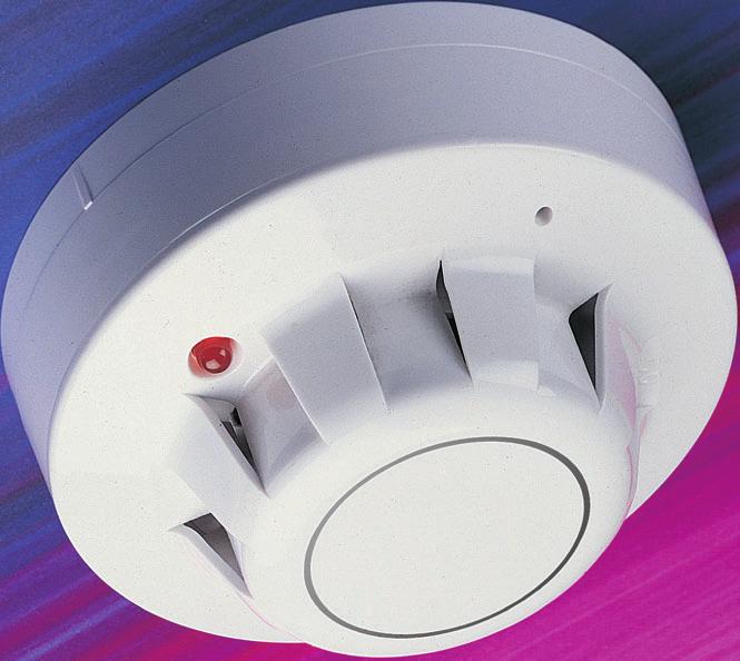
4 SERIES 65 IONISATION SMOKE DETECTOR page 4 Series 65 Standard Ionisation Smoke Detector Part nos Ionisation detector Detector with flashing LED Detector with reed switch & flashing LED Series 65 Integrating Ionisation Smoke Detector Ionisation detector Detector with flashing LED Detector with reed switch & flashing LED OPERATING PRINCIPLES The detector has a moulded self-extinguishing white polycarbonate case with wind resistant smoke inlets. Nickel plated stainless steel wiper contacts connect the detector to the base. Inside the detector case a printed circuit board has the ionisation chamber mounted on one side and the signal processing electronics on the other. The ionisation chamber consists of a reference chamber contained inside a smoke chamber (Fig. 1). The outer smoke chamber has inlet apertures fitted with insect resistant mesh. The radioactive source holder and smoke chamber form positive and negative electrodes respectively. An Americium 241 radioactive source mounted within the reference chamber irradiates the air in both chambers, producing positive and negative ions. A voltage across the electrodes produces an electric field. Ions are attracted to the electrode of the opposite sign to their own charge. Many recombine but a small electric current flows between the electrodes. At the junction between reference and smoke chambers the sensing electrode converts variations in chamber current into voltage changes. When smoke particles enter the ionisation chamber ions become attached to them with the result that the current flowing through the chambers decreases. This effect is greater in the smoke chamber than in the reference chamber, and the imbalance causes the sensing electrode to become more positive. The voltage at the sensing electrode is fed to a comparator where it is compared with a factory-set clean air reference voltage. If the monitored voltage exceeds the reference voltage, the comparator switches the alarm latch on, increasing the current drawn from the supply from about 40µA to a maximum of 75mA. This fall in the impedance of the detector is recognised by the Lid moulding Reference chamber PCB Smoke chamber Inner cover control panel as an alarm signal. The alarm latch current also illuminates the detector integral LED. A remote indicator connected between the L1 IN terminal and the R terminal will have a voltage equal to the supply voltage less 1 volt across it and so will illuminate. See page 13 for details of the remote indicator. To ensure correct operation of the detector the control panel must be arranged to supply a maximum of 33 volts DC and a minimum of 9 volts DC in normal operation. The supply may fall to 6 volts DC in alarm conditions if a supply current of at least 10mA is available at this voltage. To ensure effective illumination of the integral LED and any remote indicator, the supply to the detector should exceed 12 volts. To restore the detector to quiescent condition, it is necessary to expel any smoke and interrupt the electrical supply to the detector for a minimum of one second. Positive supply on foil holder Radioactive foil Integrated circuit 0V LED Sensing electrode Fig.1 Side view, Series 65 Optical Smoke Detector
5 INTEGRATING VERSION Circuitry in the Integrating Ionisation Smoke Detector protects against transient levels of smoke above the normal threshold level for 10 to 20 seconds. The sensitivity of the detector is not affected by this modification. OPTIONS (Apply to standard and integrating versions) 1. Flashing LED: The alarm indicating LED flashes when the detector is in a quiescent state. 2. Reed Switch and Flashing LED: A reed switch in the circuit of the detector can be magnetically activated from outside the case to initiate an alarm condition for test and commissioning purposes. A flashing LED, as outlined above, is also included. SAFETY NOTE In the United Kingdom, ionisation smoke detectors are subject to the requirements of the Radioactive Substances Act 1993 and to the Ionising Radiations Regulations 1999 made under the provisions of the Health and Safety at Work Act The detectors, independently tested by the National Radiological Protection Board (NRPB), conform to all the requirements specified in the Recommendations for ionisation smoke detectors in implemetation of radiation standards published by the Nuclear Energy Agency of the Organisation for Economic Co-operation and Development (OECD) There is no limit to the number of ionisation smoke detectors which may be installed in any fire protection system within the United Kingdom. See Certificate of Approval no TA1 issued by the Health & Safety Executive for further details. Storage regulations depend on local standards and legislation, but, in the UK, the number of ionisation smoke detectors in any building or premises shall be less than 500. See Certificate of Approval no TA3 of 1999 issued by the Health & Safety Executive for further details. At the end of their recommended working life of ten years, ionisation smoke detectors should be returned to Apollo for safe disposal or disposed of in an otherwise locally approved and environmentally safe manner. Please see A guide to the care, maintenance and servicing of Apollo products, PP2055. Guidance on storage and handling can be given by Apollo Fire Detectors and full details can be requested from: Radioactive Substances Regulation Function Environment Agency Rio House Waterside Drive Aztec West, Almondsbury Briston BS32 4UD Outside the UK, please contact the relevant national agency. ENVIRONMENTAL CHARACTERISTICS Series 65 ionisation smoke detectors operate over a temperature range of 20 C to +60 C. Ionisation detectors have some sensitivity to air movement (wind). The extent to which the sensor output will change depends on the wind speed and on the orientation of the detector relative to the wind direction. Relatively small changes in wind direction can cause significant changes in sensor output. For wind speeds up to 1m/s (200ft/min) sensitivity will change by less than 20%. Continuous operation in wind speeds greater than 2m/s (400ft/min) is not recommended. However, wind speeds up to 10m/s (2000ft/min) can be tolerated for short periods and will not under any conditions increase the probability of false alarms. Series 65 ionisation smoke detectors are supplied in individual packing with a red lid serving as a dust cover which can be left in place after fitting to prevent ingress of foreign material until commissioning of the system takes place. At this point the covers must be removed. page 5
6 page 6 TECHNICAL DATA Specifications are typical and given at 23 C and 50% relative humidity unless specified otherwise. Detector Type: Point type smoke detector for fire detection and alarm systems for buildings Detection Principle: Ionisation chamber Chamber Configuration: Twin compensating chambers using one singlesided ionising radiation source Radioactive Isotope: Americium 241 Activity: 33.3 k Bq, 0.9 µci Supply Wiring: Two wire monitored supply, polarity insensitive Terminal Functions: L1 IN and L2: supply in connections (polarity insensitive) L1 OUT and L2: supply out connections (polarity insensitive). R: remote indicator negative connection Supply Voltage: 9 to 33V DC Ripple Voltage: 2V peak to peak maximum at 0.1Hz to 100kHz Quiescent Current: 20 45µA at 24V Switch-on Surge Current: 110µA Alarm Voltage: 6 to 33V Normal Alarm Current: 61mA at 28V 52mA at 24V 18mA at 10V Alarm Indicator: Red, Light Emitting Diode (LED) Design Alarm Load: 420Ω in series with a 2V drop Holding Voltage: 6V (min) Holding Current: 10mA (min) Minimum Voltage Required to Illuminate Indicator: 12V Alarm Reset Time: 1 second Remote Output Characteristics: Remote is a current sink to the negative line limited to 17mA Calibration: Factory set to V of 0.8V Sensitivity: Nominal threshold Y value of 0.7 to EN 54 7: 2000 Temperature Range: Maximum continuous operating temperature 60 C Minimum continuous operating temperature 0 C Minimum operating temperature 20 C (no condensation or icing) Storage 30 C to +80 C Temperature Compensation: Automatic compensation by dual chambers to comply with EN 54 7: 2000 across the operating temperature range Humidity: 0% to 95% relative humidity (no condensation) Atmospheric Pressure: Automatic compensation by dual chambers to maintain sensitivity up to a height of 2000m Wind Speed: 10m/s maximum IP Rating: 23D in accordance with BS EN EMC, approvals and regulatory compliance: Refer to Page 14 of this document Dimensions: (dia. x height) Detector: 100x42mm Detector in Base: 100x50mm Weights: Detector: 102g Detector in Base: 153g Materials: Detector housing: White polycarbonate rated V-0 in accordance with UL 94. Terminals: Nickel plated stainless steel CE 3852 Alarm Reset Voltage: 1V technical data
7 SERIES 65 OPTICAL SMOKE DETECTOR Optical Smoke Detector Part nos Standard detector Detector with flashing LED Detector with reed switch & flashing LED OPERATING PRINCIPLES The Series 65 Optical Smoke Detector has a moulded selfextinguishing white polycarbonate case with wind resistant smoke inlets. Nickel plated stainless steel wiper contacts connect the detector to the base. Inside the case a printed circuit board has the optical system mounted on one side and the signal processing electronics on the other. The sensing chamber is a black moulding configured as a labyrinth which prevents penetration of ambient light. The labyrinth has a fine gauze insectresistant cover. The chamber houses an infrared light emitting diode (LED) and a photo-diode which has an integral visible-light filter as extra protection against ambient light. Every 3 seconds the LED emits a burst of collimated light, modulated at 4kHz. In clear air, light from the LED does not fall directly on the diode because the LED is positioned at an obtuse angle to the diode (as shown in Fig 2). When smoke enters the chamber, a fraction of the collimated light is scattered onto the photo-diode. If the resulting signal from the photo-diode is above a preset threshold, the LED emits two more bursts of light, this time at two-second intervals. If light is scattered onto the photo-diode by both these pulses due to the presence of smoke the detector signals an alarm state by switching the alarm latch on, increasing the current drawn from the supply from about 40µA to a maximum of 75mA. This fall in the impedance of the detector is recognised by the control panel as an alarm signal. The alarm current also illuminates the detector integral LED. A remote indicator connected between the L1 IN terminal and the R terminal will have a voltage equal to the supply voltage less 1 volt across it and so will illuminate. To ensure correct operation of the detector the control panel must be arranged to supply a maximum of 33 volts DC and a minimum of 9 volts DC in normal operation. The supply may OPTICAL CHAMBER PCB COVER CASE MOULDING fall to 6 volts DC in alarm conditions if a supply current of at least 10mA is available at this voltage. To ensure effective illumination of the integral LED and any remote indicator, the supply to the detector should exceed 12 volts. To restore the detector to quiescent condition, it is necessary to expel any smoke and interrupt the electrical supply to the detector for a minimum of one second. OPTIONS 1. Flashing LED: The integral LED flashes when the detector is in a quiescent state. 2. Reed Switch and Flashing LED: A reed switch in the circuit of the detector can be magnetically activated from outside the case to initiate an alarm condition for test and commissioning purposes. A flashing LED, as outlined above, is also included. PHOTO-DIODE INFRA-RED LED page 7 Apollo Fire Detectors LImited 1991/RHD Fig.2 Top section, Series 65 Optical Smoke Detector
8 page 8 TECHNICAL DATA Specifications are typical and given at 23 C and 50% relative humidity unless specified otherwise. Detector Type: Point type smoke detector for fire detection and alarm systems for buildings Detection Principle: Photo-electric detection of light scattered in a forward direction by smoke particles Chamber Configuration: Horizontal optical bench housing an infra-red emitter and sensor arranged radially to detect forward scattered light Sensor: Silicon PIN photo-diode Emitter: GaAs Infra-red light emitting diode Sampling Frequency: Once every 3 seconds Confirmation Frequency: Once every 3 seconds Number of Consecutive Sensed Alarm Signals Needed To Trigger Detector Alarm: 3 Supply Wiring: Two wire monitored supply, polarity insensitive Terminal Functions: L1 IN and L2: supply in connections (polarity insensitive). L1 OUT and L2: supply out connections (polarity insensitive). R: remote indicator negative connection Supply Voltage: 9 to 33V DC Ripple Voltage: 2V peak to peak maximum at 0.1Hz to 100kHz Quiescent Current: 30 50µA at 24V Switch-on Surge Current: 115µA at 24V Alarm Voltage: 6 to 28V Normal Alarm Current: 61mA at 28V 52mA at 24V 18mA at 10V Alarm Indicator: Clear light emitting diode (LED) emitting red light Design Alarm Load: 420Ω in series with 2V drop Holding Voltage: 6V (min) Holding Current: 10mA (min) Minimum Voltage Required to Illuminate Indicator: 12V Alarm Reset Voltage: 1V Alarm Reset Time: 1 second Remote Output Characteristics: Remote is a current sink to the negative line limited to 17mA Sensitivity: Nominal alarm threshold of 0.15dB/m obscuration, measured in accordance with EN 54 7: 2000 Temperature Range: 20 to +60 C (no condensation or icing). Humidity: 0% to 95% relative humidity (no condensation) Wind Speed: Insensitive to wind Atmospheric Pressure: Insensitive to atmospheric pressure Wind Speed: 10m/s maximum IP Rating: 23D in accordance with BS EN EMC, approvals and regulatory compliance: Refer to Page 14 of this document Dimensions: (dia. x height) Detector: 100x42mm Detector in Base: 100x50mm Weights: Detector: 99g Detector in Base: 150g Materials: Detector housing: White polycarbonate rated V-0 in accordance with UL 94. Terminals: Nickel plated stainless steel CE 3852 technical data

9 SERIES 65 HEAT DETECTOR Series 65 Heat Class A1R Part nos Standard detector Detector with flashing LED Detector with reed switch & flashing LED Series 65 Heat Class BR Standard detector Detector with flashing LED Detector with reed switch & flashing LED Series 65 Heat Class CR Standard detector Detector with flashing LED Detector with reed switch & flashing LED Series 65 Heat Class CS Standard detector Detector with flashing LED Detector with reed switch & flashing LED OPERATING PRINCIPLES The detector has a moulded self-extinguishing white polycarbonate case. Nickel plated stainless steel wiper contacts connect the detector to the base. Inside the case a printed circuit board holds the signal processing electronics. A pair of matched negative temperature coefficient thermistors are mounted on the PCB in such a way that one thermistor is exposed to give good thermal contact with the surrounding air while the other thermistor is thermally insulated. Under stable conditions both thermistors are in thermal equilibrium and have the same value of resistance. If air temperature increases rapidly the resistance of the exposed thermistor becomes less than that of the insulated thermistor. The ratio of the resistance of the thermistors is monitored electronically and an alarm is initiated if the ratio exceeds a factory preset level. This feature determines the rate of rise response of the detector. If air temperature increases slowly, no significant resistance difference develops between the thermistors, but at high temperatures a fixed value resistance connected in series with the insulated thermistor becomes significant. When the sum of the resistance of the insulated thermistor and the fixed resistor compared to the resistance of the exposed thermistor reaches a preset value, an alarm is initiated. The value of the fixed resistor is selected to set the detector into alarm state at a specified fixed temperature. The detector signals an alarm state by switching an alarm latch on, increasing the current drawn from the supply from about 50µA to a maximum of about 75mA. This fall in the impedance of the detector is recognised by the control panel as an alarm signal. The alarm current also illuminates the detector integral LED. A remote indicator connected between the L1 IN terminal and the R terminal will have a voltage equal to the supply voltage less 1 volt across it and so will illuminate. To ensure correct operation of the detector the control panel must be arranged to supply a maximum of 33 volts DC and a minimum of 9 volts DC in normal operation. The supply may fall to 6 volts DC in alarm conditions if a supply current of at least 10mA is available at this voltage. To ensure effective illumination of the integral LED and any remote indicator, the supply to the detector should exceed 12 volts. To restore the detector to quiescent condition, it is necessary to restore a normal temperature level and interrupt the electrical supply to the detector for a minimum of one second. OPTIONS 1. Flashing LED: The integral LED flashes when the detector is in a quiescent state. 2. Reed Switch and Flashing LED: A reed switch in the circuit of the detector can be magnetically activated from outside the case to initiate an alarm condition for test and commissioning purposes. A flashing LED, as outlined above, is also included. page 9
10 page 10 RESPONSE TIME European Standard EN54 5:2000 classifies heat detectors according to the alarm temperature and ambient operating temperature. Each heat detector classification has a static response (changing to alarm at a preset temperature) and may also have a rate of rise response (changing to alarm at or above a preset increase of temperature). The heat detector classes available in Series 65 are A1R, BR, CR, CS. The suffix R indicates that the detector has been tested and approved as a rate-ofrise detector. The suffix S indicates that the detector has been tested and approved as a static detector. Supply Voltage (V) Table 1 A1R Standard A1R Flashing LED A1R Flashing LED/ Reed Switch Quiescent Alarm Quiescent Alarm Quiescent Alarm 24 45µA 52mA 55µA 52mA 55µA 52mA 9 40µA 17mA 50µA 17mA 50µA 17mA Class Typical current against voltage charateristics for quiescent and alarm states Max application temperature C Max static response temperature C Standard Part number Flashing LED Flashing LED/ Reed Switch A1R BR CR Table 2 CS Series 65 Heat Detector Temperatures and part numbers Fig. 3 Choosing a heat detector
11 TECHNICAL DATA Specifications are typical and given at 23 C and 50% relative humidity unless otherwise specified. Detector Type: Point type heat detector for fire detection and alarm systems for buildings Supply Wiring: Two wire monitored supply, polarity insensitive Terminal Functions: L1 IN and L2: supply in connections (polarity insensitive). L1 OUT and L2: supply out connections (polarity insensitive) R: remote indicator negative connection Supply Voltage: 9 to 33V Ripple Voltage: 2V peak to peak maximum at 0.1 Hz to 100 khz Quiescent Current: See table 1 Switch-on Surge Current: As per Quiescent Current Alarm Voltage: 6 to 28V Alarm Current: See table 1 Alarm Indicator: Red light emitting diode Design Alarm Load: 420Ω in series with a 2V drop Holding Voltage: 6V Minimum Voltage Required to Light Alarm Indicator: 12V Remote Output Characteristics: Remote is a current sink to the negative line limited to 17mA Storage Temperature Range: 30 C to 120 C. Operating Temperature: 20 C to +90 C (no icing) Humidity: 0% to 95% relative humidity Atmospheric Pressure: Unaffected IP Rating: 23D in accordance with BS EN EMC, approvals and regulatory compliance: Refer to Page 14 of this document Dimensions: (dia. x height) Detector: 100x42mm Detector in Base: 100x50mm Weights: Detector: 80g Detector in Base: 131g Materials: Detector housing: White polycarbonate rated V-0 in accordance with UL 94. Terminals: Nickel plated stainless steel CE 3852 Holding technical Current: data 10mA page 11

12 SERIES 65 MOUNTING BASE Series 65 Mounting Base page 12 SPECIFICATION Full details of all bases and accessories are given in PP1089. All detectors in the Series 65 range fit into Series 60 standard mounting bases. The bases are of 100mm diameter and have five terminals marked according to their function: Line 1 in, line 1 out, line 2 in and out, remote indicator negative, earth. Detectors are polarity insensitive, so that identification of positive and negative lines is only required if a remote LED is fitted. An earth connection is not required for either safety or correct operation of detectors. The earth terminal is provided for tidy termination of earthed conductors or cable screens and to maintain earth continuity where necessary. Bases have a wide interior diameter for ease of access to cables and terminals and there are two slots for fixing screws at a spacing of 51 to 69mm. Detectors fit into bases one way only and require clockwise rotation without push force to be plugged in. They can be locked into the base by a grub screw using a 1.5mm hexagonal driver, part no OPTIONS For conventional systems which are required to operate normally when one or more detector heads have been removed, a base with a Schottky diode in LINE 1 is available (part no ). The diode conducts when the associated detector is removed, allowing power to reach devices downstream. Active monitoring can be used in systems with diode bases.

13 SERIES 65 MINI DISC REMOTE INDICATOR Mini Disc Remote Indicator SPECIFICATION page 13 The MiniDisc remote indicator is only 20mm high and 80mm in diameter. It comprises two parts the base which is installed onto a wall or soffit and the lid which is fitted to the base with a bayonet lock. An anti-tamper screw in the lid locks the unit together. A 1.5mm hexagonal driver, part number , is available from Apollo. Two pairs of keyholes are provided one for 50mm and the other for 60mm fixing centres. The MiniDisc Remote Indicator is polarity sensitive. Connect positive line to Terminal A or B and negative line to Terminal C. + From control panel Fig.3 L1 IN L1OUT EARTH L2 R L1 IN L1OUT EARTH L2 R L1 IN R L1OUT End-of-line device EARTH L2 Schematic wiring diagram of Series 65 monitored detector circuit with a common remote indicator. Remote LED + From control panel L1 IN L1OUT EARTH L2 R L1 IN L1OUT EARTH L2 R L1 IN L1OUT EARTH L2 R End-of-line device Fig.4 Schematic wiring diagram of Series 65 monitored detector circuit
14 page 14 INTERCHANGEABILITY Any detector in the Series 65 range may be replaced with any other type in the range. If, for example, a smoke detector proved unsuitable for a particular application, it could simply be replaced with a heat detector. The bases are designed specifically for Series 65 detectors and will not accept devices from other Apollo product ranges, including earlier Apollo models but with the expection of Series 60. CONTROL PANEL COMPATIBILITY Series 65 has been designed to be connected to any conventional control panel that will operate existing ranges of Apollo conventional detectors. When engineering systems with Series 65, it should be borne in mind that the alarm impedance of a detector be considered as 420 Ohms in series with a 2 volt drop with LED open circuit. Typical current against voltage characteristics for quiescent and alarm states for heat detectors are shown in Table 1. EMC All Series 65 detectors and relay bases comply with the requirements of the following EMC standards: Generic Emission Standard EN Emission standards for residential, commercial and light industrial environments Generic Emission Standard EN Emission standards for industrial environments EN : Alarm Systems Electromagnetic compatibility product family standard: immunity requirements for components of fire, intruder and social alarm systems EN Electrostatic discharge EN Radiated immunity EN Fast transient bursts EN Surge immunity EN Conducted immunity All standard detectors and the relay bases have been assessed to the additional VdS EMC requirements shown below and have demonstrated full compliance: 30V/m with 80% Am sine and 100% pulse modulation depth over the frequency ranges 415 to 467MHz and 890 to 960 MHz. Series 65 optical detector, part no , and heat detector, part no , have been declared to be compliant with the standard EN 50155: Railway applications : Electronic equipment used on rolling stock. APPROVALS AND REGULATORY COMPLIANCE The Series 65 range of detectors and relay bases is approved by a large number of certification bodies. These include approvals to EN54 : 2000 with LPCB, VdS, DIBT, BOSEC, and FG. For further information on approvals held by Apollo contact us on sales@apollo-fire.co.uk or phone Information on approvals is also held on our website Series 65 complies with the requirements of a number of European New Approach Directives such as the EMC Directive 89/336/EEC and the Construction Products Directive 89/106/EEC. Visit the Apollo website to view EC certificates of conformity issued by LPCB as a Notified Body. Copies of Declarations of Conformity issued by Apollo for all applicable New Approach Directives are available from Apollo on request. All Series 65 products will comply with the marking requirements of the WEEE Directive, 2002/96/EC. For further information on disposing of applicable electrical and electronic waste contact Apollo directly.
15
16 PP2061/2005/Issue 1 Apollo Fire Detectors Ltd Assessed to ISO 9001: 2000 Certificate number Brookside Road, Havant, Hampshire PO9 1JR, UK. Tel: +44 (0) Fax: +44 (0) sales@apollo-fire.co.uk Website: Apollo GmbH, Am Anger 31, Gütersloh, Germany. Tel: Fax: Air Products and Controls Inc., 1749 E Highwood, Pontiac, MI 48340, USA. Tel: Fax:
Series 65 Product Guide MAN 3036
 Series 65 Product Guide MAN 3036 TABLE OF CONTENTS Page No. 1 Ionisation Smoke Detector... 1 1.1 Operating Principles:... 1 1.2 Product Codes... 2 1.3 Integrating Version:... 2 1.4 Options:... 2 1.5 Safety
SERIES 65 ENGINEERING PRODUCT GUIDE
 SERIES 65 ENGINEERING PRODUCT GUIDE Wide Voltage Conventional Detectors Series 65 incorporates well-proven sensing technologies, including an Integrated Circuit based on that used in XP95 analogue addressable
Engineering Product Guide Ionisation Smoke Detectors Optical Smoke Detectors Resettable Heat Detectors
 Engineering Product Guide Ionisation Smoke Detectors Optical Smoke Detectors Resettable Heat Detectors SERIES 60 CONVENTIONAL FIRE DETECTORS Series 60 is a range of conventional fi re detectors, designed
Optical Smoke Detector Heat Detector Manual Call Point Output Unit Isolator
 TECHNICAL GUIDE Optical Smoke Detector Heat Detector Manual Call Point Output Unit Isolator The XPlorer Range XPlorer is a new range of analogue addressable detectors and interfaces developed for all who
XP95 ENGINEERING PRODUCT GUIDE
 XP95 ENGINEERING PRODUCT GUIDE Ionisation Smoke Detector Optical Smoke Detector Temperature Detector Multisensor Detector Manual Call Point Isolating Base The XP95 range of intelligent fire detectors is
ENGINEERING PRODUCT GUIDE
 RDM ENGINEERING PRODUCT GUIDE Radio linked detectors and interfaces CONTENTS Radio Detector Monitoring 1 RDM Ionisation Smoke Detector RDM Radio-linked detectors with base and interfaces Operating Principles
optical detector multisensor detector heat detector mounting bases product guide
 optical detector multisensor detector heat detector mounting bases product guide ...conventional detectors from Apollo orbis is a range of conventional detectors which has been developed and tested to
ORBIS PRODUCT GUIDE. Optical Detector. Multisensor Detector. Heat Detector. Mounting Bases
 PRODUCT GUIDE Optical Detector Multisensor Detector Heat Detector Mounting Bases 2...conventional detectors from Apollo orbis is a range of conventional detectors which has been developed and tested to
XP95 Product Guide MAN 3037
 XP95 Product Guide MAN 3037 TABLE OF CONTENTS Page No. 1 Introduction... 1 2 Application of XP95 Detectors... 1 3 Addressing and Communications... 1 4 Approvals & Regulatory Compliance... 2 5 Protocol
Conventional Smoke Detectors KFAPO
 Kingfisher Company, inc. Conventional Smoke Detectors KFAPO Features: Wide operating voltage, 9-33 VDC Advanced electronic technology Flashing LED Magnetic test switch Proven detection performance Designed
Analogue addressable devices
 Apollo XP95 Analogue addressable devices from Channel Safety Systems Apollo XP95 Analogue addressable devices The XP95 range of analogue addressable fire detectors is advanced in design, improved in performance
XP95 Sounder VAD Base
 PP2478/2016/Issue 5 XP95 Sounder VAD Base FUNC TION The XP95 Sounder Visual Alarm Device (VAD) Bases incorporates a standard mouting base with a loop-powered sounder VAD. It is used to signal a fire alarm
Orbis IS Product Guide MAN 3041
 Orbis IS Product Guide MAN 3041 TABLE OF CONTENTS Page No. 1 Introduction to Intrinsic Safety... 2 2 Range of Products... 3 3 Features of Orbis IS... 3 4 Choosing a Detector: Q & A... 3 5 Orbis IS Optical
MR300 OPTICAL SMOKE DETECTOR RANGE PRODUCT APPLICATION & DESIGN INFORMATION
 DOCUMENT CONTROL NUMBER / MR300 OPTICAL SMOKE DETECTOR RANGE PRODUCT APPLICATION & DESIGN INFORMATION 1. INTRODUCTION The MR300 range of optical smoke detectors forms part of the M300 series of plug-in
EVC-P CONVENTIONAL PHOTOELECTRIC SMOKE DETECTOR. instruction manual. evolution EVC-P Conventional Photoelectric Smoke Detector
 EVC-P CONVENTIONAL PHOTOELECTRIC SMOKE DETECTOR instruction manual Ref No: NISM/EVC-P/03 Date: Jan 2010 Issue: 3 Quality System Certificate No. 041 Assessed to BS EN ISO 9001:2000 NITTAN (UK) LTD. Hipley
Emergi-Lite Orbis detectors
 Emergi-Lite Orbis detectors Emergi-Lite Orbis brings the latest in fire detector microprocessor technology to the Firetec and Eurofire systems. Non-addressable (conventional) smoke and heat sensors respond
The supplier and installer of the system should be approved by the local civil defence authority.
 ANALOGUE ADDRESSABLE FIRE ALARM SYSTEM 1. Scope of Work The contractor shall supply, install, test and commission a modern Analogue Addressable Fire Detection and Alarm System of an approved manufacturer
Elite-A Analog Addressable Fire Control Panels (2 or 4 Loops) (Apollo Protocol)
 (Apollo Protocol)") EliteA Analog Addressable Fire Control Panels (2 or 4 Loops) (Apollo Protocol) VF1460 (2 Loops) VF1480 (4 Loops) Standard Features UL 864 9th Edition listed MultiLoop 2 Analog Addressable Loops Field upgradable
EliteA Analog Addressable Fire Control Panels (2 or 4 Loops) (Apollo Protocol) VF1460 (2 Loops) VF1480 (4 Loops) Standard Features UL 864 9th Edition listed MultiLoop 2 Analog Addressable Loops Field upgradable
4 wire conventional alarm system
 Scimitar 4 wire conventional alarm system from Channel Safety Systems Scimitar 4 wire conventional alarm system The Scimitar Fire Alarm Control System is a comprehensive range of high specification conventional
Rules for Intruder Alarm Systems
 Rules for Intruder Alarm Systems Opening detectors (Magnetic contacts) Part 1: Requirements VdS 2120en 03/96 (03) Subject 44 1 General; 2 Terms and definitions; 3 Classification 1 General 1.1 Scope These
S200Plus Triple Infra Red Flame Detector Triple Waveband Infra-Red Flame Detection
 DATASHEET S200Plus Triple Infra Red Flame Detector Triple Waveband Infra-Red Flame Detection Features: Unrivalled black body rejection over a wide range of source temperatures Triple waveband infra-red
Fire & Security Products. Siemens Building Technologies Group
 Fire & Security Products Siemens Building Technologies Group . 1 Brief overview.................................................... 1 1.1 Characteristics....................................................
4100S. The operation and functions described in this manual are available from Software Version 4100S onwards.
 4100S The operation and functions described in this manual are available from Software Version 4100S-023-013 onwards. Specifications: Item Specification Details Enclosure Steel IP30 Dimensions H x W x
INTRODUCING SOTERIA, POWERED BY COREPROTOCOL APOLLO'S MOST ADVANCED FIRE DETECTION SYSTEM
 INTRODUCING SOTERIA, POWERED BY COREPROTOCOL APOLLO'S MOST ADVANCED FIRE DETECTION SYSTEM INTELLIGENCE EFFICIENCY REFINEMENT INTEGRATION INTUITION Apollo Fire Detectors, the world-leading independent fire
MINERVA S200Plus. Fire Detection. Triple Waveband Infra-Red Flame Detection. Features: Minerva S200PLUS
 MINERVA S200Plus Triple Waveband Infra-Red Flame Detection Features: Unrivalled black body rejection over a wide range of source temperatures Triple waveband infra-red solar blind flame detection for optimum
Reflective Optical Beam Smoke Detector User Guide
 Reflective Optical Beam Smoke Detector User Guide 1. Installation IMPORTANT NOTE: The infrared beam path MUST be kept clear of obstructions at all times! Failure to comply may result in the system initiating
Product Guide MAN7030-2
 MAN7030-2 Product Guide Ampac addressable range expansion Wireless Minimsies disruption to building and occupants Enables rapid retrofit or temporary solution AS4428-9 Dual batteries for enhanced integrity
XP95 Intrinsically Safe Product Guide MAN 3054
 XP95 Intrinsically Safe Product Guide MAN 3054 TABLE OF CONTENTS. Page No. 1 Introduction to Intrinsically Safe... 1 2 Classification of Hazardous Areas... 1 3 XP95 I.S. Ionisation Smoke Detector... 3
MULTISENSOR SMOKE AND HEAT DETECTOR DMP-100 OPTICAL SMOKE DETECTOR DRP-100 FIXED TEMPERATURE / RATE-OF-RISE HEAT DETECTOR DCP-100
 MULTISENSOR SMOKE AND HEAT DETECTOR DMP-100 OPTICAL SMOKE DETECTOR DRP-100 FIXED TEMPERATURE / RATE-OF-RISE HEAT DETECTOR DCP-100 Installation Manual dmp-100_en 06/15 SATEL sp. z o.o. ul. Budowlanych 66
Apollo Accreditation. Need further information? Visit
 Product Catalogue 2016/2017 Apollo Accreditation Apollo products are certified in a global arena to meet the most exacting standards set by both our customers, and the dynamic and challenging environments
ICS Regent. Fire Detector Input Modules PD-6032 (T3419)
") ICS Regent Fire Detector Input Modules (T3419) Issue 1, March, 06 Fire detector input modules provide interfaces for 16 fire detector inputs such as smoke detectors, flame detectors, temperature detectors,
ICS Regent Fire Detector Input Modules (T3419) Issue 1, March, 06 Fire detector input modules provide interfaces for 16 fire detector inputs such as smoke detectors, flame detectors, temperature detectors,
RE-PR3-E-27 3-Phase Panel Mount 27kW
 Page 1 of 6 RE-PR3-E-27 3-Phase Panel Mount 27kW Features: Benefits: 0-10Vdc, 0-5Vdc, 4-20mA or manual via potentiometer control input Over temperature protection with auto reset Enclosed panel mounting
Reflective Beam Smoke Detector
 Reflective Beam Smoke Detector SRA-ET Features! 5-30m range! Small flat reflector! Powered directly from the zone! Full line continuity options! Automatic compensation! Approved by LPCB & VdS Description
INSTRUCTION MANUAL (ATEX/IECEx/SIL2) BExBG05D-SIL Flameproof Xenon SIL 2 Beacons For use in Flammable Gas and Dust Atmospheres
 BExBG05D-SIL Flameproof Xenon SIL 2 Beacons For use in Flammable Gas and Dust Atmospheres") INSTRUCTION MANUAL (ATEX/IECEx/SIL2) BExBG05D-SIL Flameproof Xenon SIL 2 Beacons For use in Flammable Gas and Dust Atmospheres 1) Introduction The BExBG05D-SIL is a flameproof beacon which is certified
INSTRUCTION MANUAL (ATEX/IECEx/SIL2) BExBG05D-SIL Flameproof Xenon SIL 2 Beacons For use in Flammable Gas and Dust Atmospheres 1) Introduction The BExBG05D-SIL is a flameproof beacon which is certified
EUROFLAT SERIES TYPES C... S... M...
 EUROFLAT SERIES TYPES C... S... M... AUTOMATIC CONTROL SYSTEMS FOR GAS BURNERS AND GAS BURNING APPLIANCES WITH OR WITHOUT FAN APPLICATION The electronic systems of this range are suitable to control gas
The new detector from Rafiki
 The new detector from Rafiki Three smoke detectors Three heat detectors Combined smoke/heat detector Full alarm sounder Strobe End-of-line device/loop isolator Rafiki s Multipoint ASD detector range have
DSF xx15.xx xhv Ex-Atex Ex-Atex Certified Two wire Hall Effect Speed Sensor
 DSF xx15.xx xhv Ex-Atex Product ID Type # Product # Drawing # DSF 1215.01 SHV Ex-atex (5m) 304Z-05197 113216 DSF 1415.01 AHV Ex-atex S148 304Z-05256 113351 DSF 1615.01 SHV Ex-atex (5m) 304Z-05196 113214
System 800 Addressable Fire Detection & Alarm System
 SECTION 5: page 1 Section 5: System 800 Addressable Fire Detection & Alarm System SECTION 5: page 3 10 reasons to specify 800 1 Plug and Play A user friendly panel not requiring special software tools
Audible warning devices for external alarm
 VdS SCHADENVERHÜTUNG VdS Publisher: Gesamtverband der Deutschen Versicherungswirtschaft e.v. (GDV) Büro Schadenverhütung Publishing house: VdS Schadenverhütung Rules for Intruder Alarm Systems Audible
Installation, Operating and Maintenance Manual
 STATUS ZONES CONTROLS FIRE FAULT DISABLED FIRE 1 2 3 4 5 6 7 8 TEST FAULT DISABLED 1 5 BUZZER SILENCE RESET 1 2 TEST 2 6 LAMP TEST 3 SUPPLY 3 7 SYSTEM FAULT 4 8 SOUNDERS ACTIVATE/ SILENCE 4 FAULTS INSTRUCTIONS
DUR 40Ex Intrinsically Safe SMOKE DETECTOR
 DUR 40Ex Intrinsically Safe SMOKE DETECTOR Installation and Maintenance Manual IK E317 001GB IB Issue 2 IK E317 001GB The Universal Optical Smoke Detector DUR 40Ex covered by the present manual, complies
PNC 1000 SERIES 2, 4, 8 Zone Fire Alarm Control Panel
 PNC 1000 SERIES 2, 4, 8 Zone Fire Alarm Control Panel INSTALLATION, OPERATION AND MAINTENANCE MANUAL Version: CN-PM-1000.VER1.1-12/2012 EN54 INFORMATION In accordance with EN 54-2 clause 13.7, the maximum
ALK-V PHOTOELECTRIC SMOKE SENSOR
 ALK-V PHOTOELECTRIC SMOKE SENSOR APPLICATION The HOCHIKI America ALK-V Photoelectric Smoke Sensor is particularly suited to detecting optically dense smoke typical of fires involving materials such as
Door Release Power Supply
 www.protectingpeople.co.uk Door Release Power Supply Engineer / Installation Manual Document: VI55.1 Protecting People Printed : 04/03/2004-1 - Ventcroft Ltd Door Release Power Supply Engineer / Installation
High-Power Q-Switched Diode-Pumped UV Laser Q-Series, Q305
 High-Power Q-Switched Diode-Pumped UV Laser Q-Series, Q305 The new high-power Q305 laser is an expansion of the existing Q-Series that provides a solution for demanding applications requiring faster throughput.
RS Pro Infrared Temperature Sensor
 Instruction Manual RS Pro Infrared Temperature Sensor Stock Number: 161-8103 Introduction The RS Pro Infrared Temperature Sensor is a device for measuring the temperature of the surface of a solid or liquid
Movement Detector GJD 300
 Movement Detector GJD 300 Installation & Set Up Guide Introduction A CCTV event trigger utilising two independent passive infrared detectors combined in a T05 package. Both sensors have to trigger before
Evolution Analogue Addressable Fire System
 Addressable Fire System optimum fire safety systems solutions High speed FSK protocol, uniquely resistant to noise Up to 254 addresses per loop for flexible system design Built to exceptional marine standards
Xenex Conventional Fire Detection & Alarm System
 SECTI 4: page 1 Section 4: Xenex Conventional Fire Detection & Alarm System SECTI 4: page 3 Xenex system architecture Beam Transmitter Beam Receiver End of Line Call Point Smoke Detector Smoke Detector
Interface Modules for SENTRI
 EQUIPMENT INTERFACED Data and Installation Interface s for SENTRI Low voltage (LV) / SEN-INT-INPUT 1- Interface (low voltage) SEN-INT-OUTPUT 1- & 1- Interface (low voltage) SEN-INT-4IO # 4- / Interface
D-TECT Introduction. Connecting the Unit. Quick Installation. Multi Beam Alignment & Masking. Mounting the Unit
 D-TECT 2 GJD300 Quad PIR Movement Detector Package Contents Package Contains: 1 x D-Tect 2 1 x Drilling template for fixing holes 3 x 31.75mm wall plugs 3 x 31.75mm screws 2 x Spare Sliding Curtains 2
Description. Optex Incorporated
 Optex Incorporated Description 1845 W. 205 th St. Torrance, CA 90501-1510 USA TEL (310) 533-1500 and (800) 966-7839 FAX (310) 533-5910 Doc: Model: Desc: Architect/ Engineer Specifications CX-502 PIR Intrusion
INSTRUCTION MANUAL (ATEX / IECEx)
") INSTRUCTION MANUAL (ATEX / IECEx) BExS110D and BExS110D-R Sounder For use in Flammable Gas and Dust Atmospheres BExS110D BExS110D-R 1) Warnings DO NOT OPEN WHEN AN EXPLOSIVE ATMOSPHERE IS PRESENT DO NOT
INSTRUCTION MANUAL (ATEX / IECEx) BExS110D and BExS110D-R Sounder For use in Flammable Gas and Dust Atmospheres BExS110D BExS110D-R 1) Warnings DO NOT OPEN WHEN AN EXPLOSIVE ATMOSPHERE IS PRESENT DO NOT
DI601AM Outdoor PIR/AM Detector Installation Sheet
 DI601AM Outdoor PIR/AM Detector Installation Sheet EN DE ES FR IT NL PL PT SV Figure 1 Figure 2 Figure 3 Figure 4 Figure 5 Figure 6 Figure 7 TOP Figure 8 Figure 9 TOP Long range 30m section Short/ medium
Class 1 laser beam sensor safe for your eyes
 1129 PHOTO PHOTO PARTICUR Sensor SERIES Related Information General terms and conditions... F-3 About laser beam... P.193~ guide... P.121~ General precautions... P.19 Conforming to FDA regulations (-11
ALARMLINE ANALOGUE Linear Heat Detection System
 ALARMLINE ANALOGUE Linear Heat Detection System Alarmline Analogue cable senses temperature variations by continuously monitoring the resistance of specially doped Negative Temperature Coefficient (N.T.C.)
FCP 320/FCH 320 Conventional Automatic Fire Detectors
 Fire Alarm Systems FCP 320/FCH 320 Conventional Automatic Fire Detectors FCP 320/FCH 320 Conventional Automatic Fire Detectors High reliability of detection thanks to evaluation electronics Active adjustment
Fire Alarm Systems Design. incorporating Amendment No.2. a guide to BS5839. Part1:2002
 a guide to Fire Alarm Systems Design BS5839 Part1:2002 incorporating Amendment No.2 The Regulatory Reform (Fire Safety) Order (RRO) became law on 1 October 2006 Legally you must comply! What is the RRO?
Class 1 laser beam sensor safe for your eyes
 113 Sensor SERIES Related Information General terms and conditions... F-7 About laser beam... P.199~ Sensor selection guide... P.1~ General precautions... P.11 PHOTO PHOTO PARTICUR MEASURE ITY panasonic.net/id/pidsx/global
OH110, OP110, HI110 Automatic fire detectors
 OH110, OP110, HI110 Automatic fire detectors For collective and conventional detector lines Signal processing with detector algorithms Selectable parameter sets 3 color LED indication Drift compensation
Standard detectors. General information. Product Sheet Detec on
 General information Loop detectors and modules The detector series offers ionisation smoke detectors, optical smoke detectors, heat detectors and a multisensor detector, communicating with the FMZ 5000
SOUNDER CONTROL MODULE SCM-AS4
 1 of 9 INTRODUCTION DESCRIPTION The forms part of the Nittan (UK)'s SENSORTEC-ANALOGUE range of Analogue Addressable Devices. This module is designed to control a group of bells or sounders from the detection
5000 INSTALLATION GUIDE
 5000 INSTALLATION GUIDE Table of Contents Section Page No 1. INTRODUCTION... 3 2. WARNINGS AND CAUTIONS... 3 3. UNPACKING... 3 4. INSTALLATION... 4 5. CONTROL PANEL - REMOVING ITEMS BEFORE MOUNTING...
7XG3130 ReyArc30 Optical Arc Fault Sensor Energy Management
 Reyrolle Protection Devices 7XG3130 ReyArc30 Optical Arc Fault Sensor Energy Management 7XG3130 - RA30 Optical Arc Fault Sensor Features Compact rugged design One or two optical detectors High speed arc
G4 Pulsed Fiber Laser
 G4 Pulsed Fiber Laser OEM Safety and System Integration Manual Module types B1 and B4 Module type B1 - fitted with ILLK beam delivery optic Module type B4 - fitted with ILOC beam delivery optic 1 1 Preface
VdS SCHADENVERHÜTUNG. VdS-Rules for Intruder Alarm Systems
 VdS SCHADENVERHÜTUNG VdS Publisher: Gesamtverband der Deutschen Versicherungswirtschaft e.v. (GDV) Büro Schadenverhütung Publishing house: VdS Schadenverhütung. All rights reserved. VdS-Rules for Intruder
Class 1 laser beam sensor safe for your eyes
 13 Sensor SERIES Related Information General terms and conditions... F-17 About laser beam... P.13~ Sensor selection guide... P.967~ General precautions... P.1 PHOTO PHOTO Conforming to EMC Directive Conforming
FT702LT Turbine control wind sensor gives durability a new meaning FT702LT. series
 FT702LT Turbine control wind sensor......gives durability a new meaning FT702LT series Proven High Availability The FT702LT ultrasonic anemometer is the result of FT Technologies 10 years of experience
Polycarbonate External Sounder & Strobe Unit
 Polycarbonate External Sounder & Strobe Unit Designed for maximum reliability at the most cost-effective price, the Odyssey 1E brings high security sounder technology into the residential marketplace.
Elite. GJD022 /GJD023 35m External PIR. Multi Beam Lens Data
 Elite GJD022 /GJD023 35m External PIR Multi Beam Lens Data The GJD multifunction lens fitted to the GJD Elite detector produces 9 long range beams and 9 medium to short range curtain beams. Movement across
G4 Pulsed Fiber Laser
 G4 Pulsed Fiber Laser OEM Safety and System Integration Manual Module types C1 and C2 Module type C1 - fitted with IBeam1 delivery optic Module type C2 - fitted with IBeam2 delivery optic 1 1 Preface Definition
EFBW series - BiWire Ultra control panel
 4.2 Control panels and repeater panels EFBW series - BiWire Ultra control panel Eaton s new BiWire Ultra fire detection system is unlike any other standard conventional system as the panel, conventional
D-Tect 2 GJD300 Quad PIR Movement Detector
 D-Tect GJD0 Quad PIR Movement Detector Package Contents 3. Package Contains: x D-Tect x Drilling template for fixing holes x Allen Key 3 x 3.75mm wall plugs 3 x 3.75mm screws x Spare Sliding Curtains x
EUROBOX SERIES TYPES CM... SM... MM...
 EUROBOX SERIES TYPES CM... SM... MM... AUTOMATIC GAS BURNER CONTROL SYSTEMS FOR GAS BURNERS AND GAS BURNING APPLIANCES WITH OR WITHOUT FAN Application This range of electronic gas burner control systems
Schedule of Accreditation issued by United Kingdom Accreditation Service 2 Pine Trees, Chertsey Lane, Staines-upon-Thames, TW18 3HR, UK
 2 Pine Trees, Chertsey Lane, Staines-upon-Thames, TW18 3HR, UK Langer Road Contact: Mr I Frost Felixstowe Tel: +44 (0)1394 694000 Suffolk Fax: +44 (0)1394 276030 IP11 2ER E-Mail: ian.frost@itron.com Website:
Table of Contents. Page Quick Set-up Instructions 1. Theory of Operation 2. Specifications 3. TM 1003W Controls and Connections 4
 Table of Contents Page Quick Set-up Instructions 1 Theory of Operation 2 Specifications 3 TM 1003W Controls and Connections 4 1. Power Source Connector 5 2. Alarm Output Connector 5 3. Variation Detection
Intrusion Outdoor Protection Perimeter
 Intrusion Outdoor Protection Perimeter Borders Commercial industrial Military base Correctional institution VIP Estates/Residences Communication Airports Warehouses Perimeter Sensors: the ideal solution
Industrial Solid State Contactor TE10S. Static switching of resistive loads and shortwave infrared heating tubes up to 20 kw
 Industrial Solid State Contactor TE10S Static switching of resistive loads and shortwave infrared heating tubes up to 20 kw Partial load failure (PLF) detection option User Manual Copyright Eurotherm Automation
Conventional Fire Detection
 SECTI 4: page 1 Section 4: Conventional Fire Detection Contents System Architecture Control Panel Automatic & Manual Detection Manual Call Points Smoke Detectors Heat Detectors Beam Smoke Detectors Duct
GS100-ATEX. Hazardous Areas Infra-Red Beam PULSE MODULATED ACTIVE INFRA-RED BEAM FOR HAZARDOUS AREAS ZONE 1 OR ZONE 2 GENERAL
 GS100-ATEX Hazardous Areas Infra-Red Beam PULSE MODULATED ACTIVE INFRA-RED BEAM FOR HAZARDOUS AREAS ZONE 1 OR ZONE 2 GENERAL The GS100 beam set is a detection device only, and is designed to be used in
Siemens aspirating smoke detector (ASD) for the addressed FDnet/C-NET detector line or for standalone operation
 for the addressed FDnet/C-NET detector line or for standalone operation") Sinteso Cerberus PRO FDA241, FDA221 ASD Aspirating smoke detector Siemens aspirating smoke detector (ASD) for the addressed FDnet/C-NET detector line or for standalone operation Patented technology Early
Sinteso Cerberus PRO FDA241, FDA221 ASD Aspirating smoke detector Siemens aspirating smoke detector (ASD) for the addressed FDnet/C-NET detector line or for standalone operation Patented technology Early
Control Panel Engineering and Commissioning Instructions
 Twinflex - V3 Fire Detection & Alarm System Control Panel Engineering and Commissioning Instructions (TO BE RETAINED BY THE COMMISSIONING ENGINEER) 26-0338 Issue 9 Fike s policy is one of continual improvement
D-TECT Dual Tech. GJD360 Triple Technology External Detector
 D-TECT Dual Tech GJD360 Triple Technology External Detector PACKAGE CONTENTS 1 x Dual Tech 1 x Drilling template for fixing holes 3 x 31.75mm wall plugs 3 x 31.75mm screws 2 x Spare Sliding Curtains 2
ED820-24V MODEL INSTRUCTION MANUAL. fire DETECTOR
 ED820 24V MODEL fire DETECTOR INSTRUCTION MANUAL Address: Enigma House, Enigma Business Park, Malvern, Worcestershire, WR14 1GD Tel: 44 (0)1684 891500 Fax: 44 (0)1684 891600 Email: sales@electronicdevices.co.uk
AVAILABLE TO DOWNLOAD ON THE APOLLO APP. Pocket guide to. Fire Alarm Systems Design BS Standard
 Pocket guide to Fire Alarm Systems Design BS 5839-1 Standard AVAILABLE TO DOWNLOAD ON THE APOLLO APP The Regulatory Reform (Fire Safety) Order (FSO) became law on 1 October 2006 Legally you must comply!
TrueAlarm Smoke Detectors
 UL, ULC Approved* TrueAlarm Smoke Detectors TrueAlarm Photoelectric Smoke Detector with TrueSense Smoke/Heat Detection Features detection. If any of these alarm conditions are experienced, an alarm is
HOA1888 Series. Infrared Assemblies Wide Gap Transmissive Sensor. MICRO SWITCH Sensing and Control
 Wide Gap Transmissive Sensor HOA1888 Series FEATURES Choice of phototransistor or photodarlington output Visible ambient light and dust protective filter 12 mm (0.47 in.) slot width Snap-in housing The
Datasheet for Models: 1SFWR 1SFW. NEW range. capability. 230V Mains Fast-Fit Ionisation Smoke Alarms. Key Features. Applications
 Datasheet for Models: 1SFWR 1SFW NEW range Developed specifically for social and private housing, Slick is the only range of fast-fit rechargeable ionisation and optical smoke alarms, and heat alarms guaranteed
HART XL High Sensitivity Smoke Detection
 High Sensitivity Smoke Detection The Hart XL High Sensitivity Smoke Detection system (HSSD) is an aspirating fire detection system designed to give very early indication of an incipient fire condition.
Thermo-Sealer. Manual Heat Sealer. User Manual
 Thermo-Sealer Manual Heat Sealer User Manual Thermo-Sealer Contents Page Page Introduction 2 Safety 2 Declaration of conformity 3 Caution and safety signs in accordance with IEC 417 4 Unpacking 4 Technical
ABB Instrumentation. Specifications. COMMANDER 150 Universal Process Indicator. the 1 /8 DIN indicator to match all your display requirements
 Specifications COMMANDER 150 Universal Process Indicator High visibility 6-digit LED display the clearest view of your process status 0.1% measurement accuracy precise indication of process measurement
C-Bus Four Channel Analogue Output Unit Installation Instructions
 C-Bus Four Channel Analogue Output Unit Installation Instructions 5504AMP Series REGISTERED PATENT Table of Contents Section... Page 1.0 Product Range...3 2.0 Description...3 3.0 Capabilities...3 4.0 Wiring
INSTRUCTION MANUAL (ATEX / IECEx)
") INSTRUCTION MANUAL (ATEX / IECEx) BExTS110D Flameproof Sontel 1) Introduction The BExTS110D is a flameproof Sontel telephone sounder which is certified to the meet the requirements of the ATEX directive
INSTRUCTION MANUAL (ATEX / IECEx) BExTS110D Flameproof Sontel 1) Introduction The BExTS110D is a flameproof Sontel telephone sounder which is certified to the meet the requirements of the ATEX directive
Installation and user manual for the BiWire / Conventional Repeater Panel
 Panel EFBWCV-REPEATER Contents Introduction.... 3 Purpose... 3 The Panel.... 3 Indication Equipment (IE).... 3 Power Supply Equipment (PSE).... 4 System Wiring.... 5 Status Indications.... 5 Repeater I/O....
Addressable Detectors & Bases
 Edwards Signaling Catalog u Intelligent Initiating Addressable Detectors & Bases Detectors: E-PD, E-PHD, E-HD Bases: B4U, RB4U, IB4U, SB4U Overview Edwards intelligent addressable detectors are meticulously
2015 Amphenol Advanced Sensors. Jinton Industrial Park, Wujin, Changzhou, Jiangsu, China. Web:
 AAS-920-668A Nov., 2015 2015 Amphenol Advanced Sensors Jinton Industrial Park, Wujin, Changzhou, Jiangsu, China Web: www.amphenol-sensors.com Table of Contents 1. Description...................................................................
Laboratory Honeywell Technology Solutions, Bangalore-EMC Lab, 19/2, Devarabisanahalli Village, K.R. Puram, Varthur Hobli, Bangalore, Karnataka
 Last Amended on 07.10.2015 Page 1 of 18 I. EMC Test Facility 1. Electrical and Electronic Products, Process Control Devices, Lighting Control Products, Sensing and Control Devices, Electromechanical Products,
SPECIFICATIONS PARTICLE SENSOR KS-41B Higashimotomachi, Kokubunji, Tokyo , Japan
 SPECIFICATIONS PARTICLE SENSOR KS-41B 3-20-41 Higashimotomachi, Kokubunji, Tokyo 185-8533, Japan No. 11025-4E 18-01 Printed in Japan Outline The KS-41B is a sensor which uses the light scattering method
Test Report Garvan Enterprises Limited
 Test Report 8526255. Garvan Enterprises Limited Page 1 of 14 Introduction. This report has been prepared by A Reeve and relates to the activity detailed below: Job/Registration Details Job number: 8526255
Open-area Smoke Imaging Detection (OSID)
") Open-area Smoke Imaging Detection (OSID) OSID Smoke Detection Open-area Smoke Imaging Detection (OSID) by Xtralis is a new innovation in projected beam smoke detection technology. By using advanced dual
Open-area Smoke Imaging Detection (OSID) OSID Smoke Detection Open-area Smoke Imaging Detection (OSID) by Xtralis is a new innovation in projected beam smoke detection technology. By using advanced dual