AFRL-RX-TY-TR
|
|
|
- Anastasia Singleton
- 6 years ago
- Views:
Transcription

1 AFRL-RX-TY-TR FIELD DEMONSTRATION OF A CENTRIFUGAL ULTRA HIGH PRESSURE (UHP) P-19 Jennifer L. Schroeder Fire Science Solutions, LLC 9117 Sunshine Drive Youngstown, FL Michael J. McDonald Applied Research Associates, Inc P.O. Box Tyndall Air Force Base, FL John R. Hawk and R. Craig Mellerski Air Force Research Laboratory 139 Barnes Drive, Suite 2 Tyndall AFB, FL Contract No. FA D-0001 MARCH 2010 DISTRIBUTION A: Approved for public release; distribution unlimited. AIR FORCE RESEARCH LABORATORY MATERIALS AND MANUFACTURING DIRECTORATE Air Force Materiel Command United States Air Force Tyndall Air Force Base, FL
2 NOTICE AND SIGNATURE PAGE Using Government drawings, specifications, or other data included in this document for any purpose other than Government procurement does not in any way obligate the U.S. Government. The fact that the Government formulated or supplied the drawings, specifications, or other data does not license the holder or any other person or corporation; or convey any rights or permission to manufacture, use, or sell any patented invention that may relate to them. This report was cleared for public release by the Air Force Research Laboratory, Materials and Manufacturing Directorate, Airbase Technologies Division, Public Affairs and is available to the general public, including foreign nationals. Copies may be obtained from the Defense Technical Information Center (DTIC) ( REPORT NUMBER AFRL-RX-TY-TR HAS BEEN REVIEWED AND IS APPROVED FOR PUBLICATION IN ACCORDANCE WITH ASSIGNED DISTRIBUTION STATEMENT. //SIGNATURE// //SIGNATURE// R. CRAIG MELLERSKI, DR-III SANDRA R. MEEKER, DR-IV Work Unit Manager Chief, Deployed Base Systems Branch //SIGNATURE// ALBERT N. RHODES, PhD Acting Chief, Airbase Technologies Division This report is published in the interest of scientific and technical information exchange, and its publication does not constitute the Government s approval or disapproval of its ideas or findings.
3 REPORT DOCUMENTATION PAGE Form Approved OMB No The public reporting burden for this collection of information is estimated to average 1 hour per response, including the time for reviewing instructions, searching existing data sources, gathering and maintaining the data needed, and completing and reviewing the collection of information. Send comments regarding this burden estimate or any other aspect of this collection of information, including suggestions for reducing the burden, to Department of Defense, Washington Headquarters Services, Directorate for Information Operations and Reports ( ), 1215 Jefferson Davis Highway, Suite 1204, Arlington, VA Respondents should be aware that notwithstanding any other provision of law, no person shall be subject to any penalty for failing to comply with a collection of information if it does not display a currently valid OMB control number. PLEASE DO NOT RETURN YOUR FORM TO THE ABOVE ADDRESS. 1. REPORT DATE (DD-MM-YYYY) 2. REPORT TYPE 3. DATES COVERED (From - To) 4. TITLE AND SUBTITLE 5a. CONTRACT NUMBER 5b. GRANT NUMBER 5c. PROGRAM ELEMENT NUMBER 6. AUTHOR(S) 5d. PROJECT NUMBER 5e. TASK NUMBER 5f. WORK UNIT NUMBER 7. PERFORMING ORGANIZATION NAME(S) AND ADDRESS(ES) 8. PERFORMING ORGANIZATION REPORT NUMBER 9. SPONSORING/MONITORING AGENCY NAME(S) AND ADDRESS(ES) 10. SPONSOR/MONITOR'S ACRONYM(S) 11. SPONSOR/MONITOR'S REPORT NUMBER(S) 12. DISTRIBUTION/AVAILABILITY STATEMENT 13. SUPPLEMENTARY NOTES 14. ABSTRACT 15. SUBJECT TERMS 16. SECURITY CLASSIFICATION OF: a. REPORT b. ABSTRACT c. THIS PAGE 17. LIMITATION OF ABSTRACT 18. NUMBER OF PAGES 19a. NAME OF RESPONSIBLE PERSON 19b. TELEPHONE NUMBER (Include area code) Standard Form 298 (Rev. 8/98) Prescribed by ANSI Std. Z39.18
4 TABLE OF CONTENTS Section Page LIST OF FIGURES... v LIST OF TABLES... vi PREFACE... vii 1.0 INTRODUCTION Background Scope Objective PHASE I; OSHKOSH TECHNOLOGY DEMONSTRATOR VEHICLE TESTING SUMMARY Phase I Vehicle Description Phase I Testing Phase I Conclusions Phase I Recommendations PHASE II; FIELD DEMONSTRATION OF FIVE MODIFIED P-19 S SUMMARY UHP P-19c Demonstration Locations Training UHP P-19c Field Demonstration Overview Foam Quality Methods and Results Pump Cycle Methods and Results Three-Dimensional Engine Nacelle Fire Methods and Results Pool Fire Methods and Results Cold Weather Evaluations Design Issues Identified During Testing PHASE II; FIELD DEMONSTRATION OF FIVE MODIFIED P-19 S Hardware Components Darley Centrifugal Pump Elkhart Brass Bumper Turret and Nozzles Akron Brass Bumper Turret and Nozzles Oshkosh Truck Corporation HMA Fire Apparatus UHP P-19c Demonstration Locations Training UHP P-19c Field Demonstration Overview Instrumentation and Equipment Foam Quality Methods and Results Pump Cycle Methods and Results Three-Dimensional Engine Nacelle Fire Methods and Results Pool Fire Methods and Results Cold Weather Operation Design Issues Identified During Testing Compressed Air Foam System UHP Handline and Turret Operation Pump and Roll in Handline Mode iii
5 Handline Operations and Problems with the Gear Shift Akron Brass Handline Nozzle Temperatures Elkhart Brass Handline Nozzle Clogging Pump Gear Box Cooling Field Demonstration Database CONCLUSIONS RECOMMENDATIONS REFERENCES APPENDIX A - Memorandum from W.S. Darley & Co on the CRADA TD Pump Failure APPENDIX B - Correspondence from Elkhart Brass on UHP Nozzle Redesign APPENDIX C - Oshkosh Engineering Technical Reports APPENDIX D - Refractometer Calibration Curves APPENDIX E - Phase II Field Prototype Data ACRONYMS GLOSSARY iv
6 LIST OF FIGURES Figure Page 1. The Technology Demonstrator TD Centrifugal Pump Installation for UHP P-19c Pumping System and Hydraulic Drive for UHP P-19p The Darley Six Stage Centrifugal Pump The Elkhart Brass Combination UHP and Hydro-Chem Turret Akron Brass UHP Nozzle in Fog Pattern The Combination Akron Brass UHP and Hydro-Chem Turret UHP P-19c Cab Control Panel HMA Force Feedback Joystick Davis-Monthan Live Fire Burn Facility Dyess Live Fire Burn Facility Ellsworth Live Fire Burn Facility Mountain Home Live Fire Burn Facility Tyndall Live Fire Burn Facility Atago Pal-1 Digital Refractometer Atago PR-32 Digital Refractometer Foam Concentration Measurements for the UHP Turret Foam Concentration Measurements for the CAF Turret Foam Concentration Measurements for the UHP Handline Foam Concentration Measurements for the CAF Handline Diagram of the F100 Engine Nacelle UHP Turret Fire Application Rates CAF Turret Fire Application Rates Hydro-Chem Turret Fire Application Rates UHP Handline Fire Application Rates CAF Handline Fire Application Rates Hydro-Chem Handline Fire Application Rates v
7 LIST OF TABLES Table Page 1. Performance Specifications for the Darley Six Stage Centrifugal Pump Effective Burn Areas Field Evaluation Test Sequence NFPA 412 and Requirements for Foam Quality for Vehicles >528 to 1585 Gallons Discharge Distance Data Summary for UHP and CAF Systems Foam Quality Data for the Elkhart Brass and Akron Brass UHP Bumper Turrets Foam Quality Data for the Compressed Air Foam Bumper Turret Foam Quality Data for the Akron Brass UHP Handline Foam Quality Data for the Compressed Air Foam Handline Pump Cycle Testing Summary F100 Engine Nacelle Extinguishment Times for Akron Brass UHP Handline Total Number of Fires Requested and Completed on the UHP P-19c Nominal Foam Solution Flow Rates Summary of Application Rates of Turret Systems Statistical Comparisons of UHP-P19c Agent Application Rates with FEET Results Application Rate in Cold Weather vi
8 PREFACE This report details field demonstration of the Ultra High Pressure (UHP) fire fighting technology that was initially researched and developed (R&D) by the Air Force Research Laboratory (AFRL) in Over the past seven years, AFRL has conducted extensive R&D to scale UHP from 10 gallons per minute (gpm) on the First Response Expeditionary (FRE) fire fighting system to the 300 gpm system used for field evaluation in this report. The ultimate goal of UHP technology was to develop a fire fighting system that exceeded the effectiveness of current technology while reducing the amount of agent needed to extinguish a burning aircraft. AFRL has shown through the careful scaling of the technology that a greater than 300% improvement in fire fighting efficiency can be obtained using UHP. This is revolutionary technology advancement. AFRL would like to acknowledge several organizations for their contributions to this project including the Air Force Civil Engineering Support Agency, the five Air Force bases Davis- Monthan, Dyess, Ellsworth, Mountain Home, and Tyndall, W.S. Darley Co, Oshkosh Corporation, Elkhart Brass, Akron Brass and HMA Fire Apparatus. Without the support of the Air Force Civil Engineering community and the fire equipment manufacturers, this technology would not be transitioning to the commercial sector. vii
9 1.0 INTRODUCTION 1.1 Background Headquarters Air Force Civil Engineer Support Agency (AFCESA), is finalizing the specifications for the next generation ARFF vehicle for deployed locations. The P-19 has been a highly successful Aircraft Rescue Fire Fighting (ARFF) vehicle over the years, becoming the backbone for U.S. military operations both stateside and overseas. However, this aging fleet of vehicles, built in the mid-1980 s, must be replaced in the near future, creating the need for a new fire fighting vehicle. In recent years, AFRL has pioneered the development of revolutionary concepts in fire fighting equipment, techniques and strategy that will provide the basis for new military ARFF vehicle designs. The major goal for the next generation deployable ARFF vehicle is to increase the fire fighting capability using innovative technologies with current fire fighting agents. Ultra High Pressure (UHP) technology was first investigated by AFRL in 2002 for small hydrocarbon pool and running fuel fires. Over the past six years, AFRL has proven the technology can be scaled to exceed the level of protection provided by 500 gallons per minute (gpm) systems using 2/3rds less water than conventional low pressure, high flow systems. AFRL completed prototype design and testing of a 300 gpm system with the efficiency of a system three times the size and flow. Evaluation of UHP technology in a relevant environment reduces risk to the Air Force as the technology transitions to industry. The purpose of Phase I (AFRL-ML-TY-TR ) was to test and evaluate the prototype six-stage centrifugal pump developed by W.S. Darley Co (Darley) on the Oshkosh Technology Demonstrator (TD). The purpose of this effort (Phase II) was to demonstrate the five modified A/S32P-19 (P-19) fire trucks to include UHP water/foam, Compressed Air Foam (CAF) and Dry Chemical (DC) delivery systems at five different Air Force bases. The trucks were evaluated for reliability of the UHP pump and associated equipment; fire fighting effectiveness using Air Force firefighters versus AFRL fire technicians who have extensive UHP experience; and ease of operation for firefighters in the field that have never used UHP technology. Results from Phase II were analyzed to validate AFRL s Phase I results and conclusions from an operator's perspective. The Air Force Fire Chief and the Fire Chiefs at the Major Air Commands have observed multiple demonstrations of the UHP technology and agreed that substantial improvement in the efficiency of fire fighting agent has been achieved. The demonstration information can be used by the Air Force Fire Chief to provide specifications for the next generation of ARFF vehicles, including the replacement for the deployable P Scope This report provides a summary of the results of the demonstration AFRL performed on the UHP fire fighting system and details of the field evaluations at five Air Force bases of five modified A/S32P-19 (P-19) fire trucks (UHP P-19c) to include UHP water, CAF and Dry Chemical delivery systems. 1
10 1.3 Objective The objective of the field trials was to demonstrate UHP and the new pump technology reliability, fire fighting effectiveness and ease of operation for firefighters in the field. The Air Force bases chosen for this program were Davis-Monthan (DM), Dyess (D), Ellsworth (E), Mountain Home (MH) and Tyndall (T). This report documents discharge distance, expansion ratio, drain time and extinguishment performance for the 300 gpm UHP turret, the 20 gpm UHP handline, the 300 gpm Hydro-Chem turret and the 45 gpm Hydro-Chem handline. Fire suppression tests were conducted to demonstrate extinguishment time and agent use for firefighters in the field versus efficiencies demonstrated in a more controlled laboratory environment. The modification and field demonstrations of each of the fire trucks validated UHP for a new future vehicle buy using these technologies. Although 121 live fire tests were performed to obtain as much objective data as possible, all subjectivity could not be eliminated due to variations in conditions such as wind, humidity and temperature during the test fires. Therefore to compensate for a lack of statistical confidence, the mature technology was put through rigid performance testing at five different installations by functional experts (firefighters). 2
 to develop a dual agent 300 gallons per minute (gpm) UHP/CAF fire truck using a single centrifugal pump.")
11 2.0 PHASE I; OSHKOSH TECHNOLOGY DEMONSTRATOR VEHICLE TESTING SUMMARY In May 2006, AFRL entered into a Cooperative Research and Development Agreement (CRADA) with Oshkosh to modify an existing fire vehicle platform (Technology Demonstrator- TD) to develop a dual agent 300 gallons per minute (gpm) UHP/CAF fire truck using a single centrifugal pump. Previous work by AFRL/RXQD used reciprocating pumps to produce the required pressure and flow. Typically fire trucks use centrifugal pumps because they are smaller, simpler in design and ultimately more reliable in the field. This TD was designed and modified by Oshkosh to incorporate centrifugal pumps and the CAF system. The pump was developed from a concept originated by W. S. Darley & Co. (Darley), a longstanding provider of fire pumps and associated equipment. Evaluation of a Centrifugal Pump System for Ultra High Pressure and Compressed Air Foam Fire Fighting 3 (AFRL-RX-TY-TR ) provides detailed test methods and data. A summary of the vehicle design, conclusions and recommendations is provided as background for the subsequent field evaluations of the five modified UHP-19s. 2.1 Phase I Vehicle Description The platform chosen for the CRADA program was an Oshkosh T-1500 fire truck (Figure 1) with a 540 horsepower Detroit Diesel engine, power divider with two power take-offs (PTO), with pump and roll capability referred to as the Technology Demonstrator (TD). Modifications made by Oshkosh to the TD included installation of the UHP system, the CAF system, a combined UHP/CAF bumper turret, UHP and CAF handlines, and associated instrumentation and controls. Figure 1. The Technology Demonstrator 3
 developed by AFRL/RXQD.")
12 A new six-stage centrifugal pump (Figure 2) was designed and built by W. S. Darley & Co. (Darley) and Oshkosh specifically for this project recognizing that this technology could revolutionize ARFF. The centrifugal pump provided a simpler, more compact and less expensive pumping system than the plunger pump system previously used on the plunger pump UHP P-19 (UHP P-19p) developed by AFRL/RXQD. The UHP P-19p was developed as a proof of concept system using commercial-off-the-shelf (COTS) components exclusively. The COTS components used were a centrifugal pump and three UHP CAT PUMP plunger pumps. Power was supplied to each of these four pumps using a separate hydraulic motor and hydraulic pump. These components (Figure 3) were located in the engine compartment, along the left side of the chassis, and behind the water tank. In comparison, the TD used a single centrifugal pump that was shaft driven from the power divider. The TD s centrifugal pump fit in a compact package along the left side of the truck chassis. The three plunger pumps for the UHP P-19p cost $15, each 4. The hydraulic motors, pumps, hoses, hydraulic tank, hydraulic control system, and hydraulic pump belt drive increase the cost of the total system to approximately $85,000. The single Darley UHP centrifugal pump that replaced these items was estimated to cost $25, In addition to the cost savings, the new centrifugal pump allowed room on the TD (and later the UHP P-19c) for the original 1000 gallon water tank and provided a pump similar in design to the original centrifugal pump found on the P-19, which provided familiarity to vehicle maintenance personnel. Figure 2. TD Centrifugal Pump Installation for UHP P-19c 4
13 Hydraulic Motor Hydraulic Pump UHP Plunger Pumps Hydraulic Motors Centrifugal Water Pump Hydraulic Pumps Hydraulic Fluid Tank Figure 3. Pumping System and Hydraulic Drive for UHP P-19p 2.2 Phase I Testing The truck was delivered to the AFRL/RXQD to perform experiments/testing for foam quality, discharge distance and extinguishment evaluations. These tests were prematurely terminated due to failure of the new centrifugal pump that was the result of reusing a snap ring. Although no design changes were required to correct this failure, testing was discontinued. From the tests that were accomplished, the performance indicated that the centrifugal pump could supply the pressure and flow previously demonstrated using the piston pump technology. 2.3 Phase I Conclusions 1. The TD showed promise that the centrifugal pump configuration could provide the fire fighting capabilities established in the program goals and NFPA 412 requirements, particularly with the UHP system. 2. The performance of the UHP turret provided greater pressure and flow than the program goals. Expansion ratio, drain times and discharge distance met requirements in NFPA 412. Extinguishment using the TD used less agent than that the standard P-19 as determined during the Fire Extinguishing Effectiveness Testing 6 (FEET). 3. The UHP handline on the TD was modified due to firefighter concerns about reaction force, ultimately resulting in decreased pressure, flow and discharge distance because the orifice was inserted at the hose reel instead of internal to the nozzle itself. The TD was equipped with a nozzle orifice that could not be adjusted. If a nozzle with the appropriate orifice size were available, the reaction force could have been reduced without significantly impacting nozzle pressure and discharge distance. The expansion ratio demonstrated by the TD 5
14 handline was greater than the value required by NFPA 412. Fire extinguishment efficiency exceeded NFPA requirements, indicating a reduction in agent used. 4. The CAF turret also met the requirement for flow, but did not meet the pressure requirement. There were no CAF fires conducted with the TD because of the pump failure. 5. The pump failure was the result of reusing snap rings during repeated assembly and disassembly procedures. The design of the pump was not defective, and it would not have failed if new snap rings had been installed. The five pumps tested in the P-19 retrofit program used new snap rings and no failures were experienced. 2.4 Phase I Recommendations 1. AFCESA should continue with the P-19 Retrofit Program and AFRL should evaluate the performance of the five trucks to validate that preproduction units can meet specifications under field conditions. 2. The poppet foam system should be replaced with a system that meets the foam proportioning requirements for each of the four discharge systems. 3. Continue reliability testing on the Darley pump to determine life cycle costs and mean time between failures. 4. Additional tests should be conducted on system pressure, flow and fire extinguishment to provide statistical information with at least 90% confidence levels. 6
15 3.0 PHASE II; FIELD DEMONSTRATION OF FIVE MODIFIED P-19 S SUMMARY 3.1 UHP P-19c Demonstration Locations Five Air Force bases were chosen based on their ability to conduct testing of the prototype vehicles using JP-8 hydrocarbon fuel for live fire testing. The bases are also located throughout the United States and offer a variety of environments, weather conditions and fire pit configurations. The Air Force bases chosen for this program include Davis-Monthan, Dyess, Ellsworth, Mountain Home and Tyndall. 3.2 Training AFRL provided training on each UHP modified P-19 vehicle upon delivery from Oshkosh. The firefighters who extinguished the fires were provided with classroom instruction and hands-on training from AFRL personnel with their modified UHP P-19c vehicle to gain a level of comfort with the capabilities, limitations and differences in the vehicle versus a standard P-19. Oshkosh provided training to the vehicle maintenance personnel upon delivery of the vehicle, including maintenance of the new fire fighting system, basic troubleshooting and repairs. Oshkosh provided an overview of the major systems, how they functioned, maintenance items, the frequency of maintenance, and contact information for the fire department and vehicle maintenance personnel in the event of a problem. Each base was provided with a supplemental manual to describe the modifications to the vehicle. 3.3 UHP P-19c Field Demonstration Overview The field demonstrations consisted of system checkout to assure the function of the pump, turrets, handlines and pressures for each foam system; and foam quality including foam proportioning, fire extinguishing effectiveness, discharge distance, expansion ratio and drain time. Demonstration testing also adhered to the standards outlined in NFPA. 3.4 Foam Quality Methods and Results The field evaluations consisted of system checkout and foam quality. System checkout assured the function of the pump, turrets, handlines and pressures for each foam system. Foam quality evaluations included foam proportioning, fire extinguishing effectiveness, discharge distance, expansion ratio and drain time. The measured foam concentration for the UHP turret was within tolerance ranges for one test at Dyess, all tests at MH and all tests at Tyndall. All foam concentration tests conducted at DM and Ellsworth were outside the tolerance ranges. Large variances in foam concentration were likely due to the plate and plunger system used to meter the foam. The foam proportioning system on the Tyndall vehicle was not functioning towards the end of fire testing and despite installing a new system, the foam was eventually premixed to the desired concentration in the water tank because the problem could not be resolved. Premixed Aqueous Film Forming Foam (AFFF) was used for all fire testing of the CAF and Hydrochem turret and handline. 7
16 Foam quality results for the CAF bumper turrets were all within requirements except for the drain time at Dyess. The foam concentration measurements for the CAF bumper turrets were within National Fire Protection Association (NFPA) tolerance ranges for one test at DM, one test at Ellsworth and three tests at MH. Due to foam proportioning malfunctions mentioned above, all other tests were outside the tolerance range and the measurements for Tyndall were especially high at 6.7% and 7.5%. The foam expansion ratio and drain time for the Akron Brass UHP handline were all above the minimum requirements however, all the foam concentration measurements except two from DM were below the NFPA tolerance range. Foam proportioning was most difficult to control on the low flow 20 gpm UHP handline because of the way the plate and plunger system works by introducing foam through an orifice in the plate. While fluid calculations were done to determine the proper orifice size to obtain the correct foam proportion, metering at small flow rates is difficult to control with any degree of accuracy. The expansion ratio and drain time results for the CAF handline exceeded the NFPA minimum requirements. MH and Ellsworth each had foam concentration measurements that fell within tolerance ranges while DM and Tyndall were both below the minimum range. While DM had the lowest foam concentration measurements, the foam expansion ratio and drain time were well above the minimum requirements. 3.5 Pump Cycle Methods and Results AFRL was not provided with funds to complete time to failure analysis on the new centrifugal pump so pump cycle testing was determined to be the next best test method to stress the pump and test the reliability of the new technology. The Centrifugal Pump UHP P-19 (UHP P-19c) was operated using water only in an on/off cycle mode. Turning the pump completely on and off is one of the most mechanically stressful operating procedures. Hour and cycle counters were installed to obtain reliability data on all water and foam fire fighting systems. Five meters were installed, tracking operation of the UHP pump, UHP turret, UHP handline, CAF turret and CAF handline. Only data on the UHP pump and UHP turret are reported because the other systems were not used for pump cycle testing. 3.6 Three-Dimensional Engine Nacelle Fire Methods and Results After the original test plan was written and approved, AFCESA requested Tyndall to complete a series of fire evaluations on the three-dimensional running fuel fire engine nacelle mockup. These tests evaluated effectiveness of low flow UHP handlines on hidden compartment running fuel fires and the ease of use for fighting these difficult fires. Testing was only conducted at Tyndall since AFRL is the only base that has this equipment. The 20 gpm UHP handline was able to successfully extinguish all three fires and was comparable to the performance of Halon The UHP P-19c handline extinguishment times ranged from 8.41 to with an average of seconds using 4.38 gallons (36.55 lbs) of agent. 8
17 3.7 Pool Fire Methods and Results The application rates from the UHP P-19c field evaluations are shown in comparison to data obtained from the Fire Extinguishing Effectiveness Testing (FEET) completed at Tyndall in 2004 for the UHP, CAF and Hydro-Chem turrets systems. Handline comparisons were not conducted during FEET. All UHP P-19c testing was completed using the foam proportioning systems on the vehicles with the exception of the CAF and Hydro-Chem handline fires conducted at Tyndall because the foam proportioner did not function correctly. The purpose of the live fire evaluations was to show that even with minimal training and experience, firefighters can use UHP technology very effectively. Forty-five fires were completed using the UHP bumper turret. UHP turret operations averaged gallons per square foot (gsf) needed to extinguish the fire as compared to gsf observed during the FEET study. Eleven fires were completed using the CAF bumper turret. UHP P-19c CAF turret operations averaged gsf as compared to gsf observed during the FEET study. Eleven fires were completed using the Hydro-Chem bumper turret. The UHP P-19c Hydro- Chem turret operations averaged gsf as compared to gsf observed during the FEET study. Twenty-one fires were completed using the UHP handline. The FEET study did not evaluate handline operations, so no comparable data exists. Typically, application rates are improved by a factor of ten when compared to turret operations due to the firefighter having greater ability to control the application of the agent, resulting in less waste. The UHP handline average gsf application rate in comparison to gsf for the UHP turret. Fifteen fires were completed with the CAF handline with an average application rate of gsf (0.038 gsf for CAF turret). Eighteen fires were completed with the Hydro-Chem handline with an average application rate of gsf (0.023 gsf for the Hydro-Chem turret). 3.8 Cold Weather Evaluations Four fires using different fire fighting systems were completed by Ellsworth at temperatures near or below freezing with burning JP-8 on top of the frozen fire pit surface. The five vehicles used for this field evaluation were not modified with any additional cold weather protection for the new fire fighting system other than what already existed on the vehicle. Normal storage, maintenance and operational guidelines were followed for cold weather environments. While testing in sub-freezing temperatures was not required for the field evaluation, the results showed that the UHP P-19c was still effective at extinguishing fires using UHP and CAF plus dry chemical in the form of Hydro-Chem. The handline fires were challenging for the firefighters as they had to extinguish the fires while walking on a sheet of ice. Review of the videos from 9
18 each fire showed that the sub-freezing temperatures did not have any negative effects on agent stream characteristics or fire extinguishment effectiveness. 3.9 Design Issues Identified During Testing During field evaluations, several engineering design issues were identified. While most issues were corrected either in the field or at the manufacturer, some issues were not resolved either because they were related to the P-19 and systems not related to the modified fire fighting package or they were issues that needed to be addressed by the component manufacturer. These issues included the air compressor (which was fixed), concurrent handline and turret operations (which was fixed), ability to use the handline and the vehicle to move at the same time, UHP handline heating up, UHP handline clogging, and a cooling system is required for pump gear box. 10

19 4.0 PHASE II; FIELD DEMONSTRATION OF FIVE MODIFIED P-19 S 4.1 Hardware Components AFRL has maintained a partnership with several manufacturers over the development of the UHP technology, which has made the prototype vehicle a reality. The following sections give some details on three main components that were designed specifically for the UHP P-19c, but do not represent all the manufacturers who have worked with AFRL during the seven year development of UHP from 10 gpm to 300 gpm Darley Centrifugal Pump W.S. Darley & Co designed, engineered, fabricated and tested a new six stage centrifugal pump capable of producing low and ultra high pressure with a single pump (Figure 4). The pump specifications for both low and ultra high pressure are shown in Table 1. The first stage provides low pressure while the other five stages build the pressure to UHP. Development started in 2006, and in 2007 Darley finalized a prototype for testing. The first unit was used for testing in the Oshkosh TD. Unfortunately, a problem with a snap ring caused the pump to fail but identified an issue that could easily be addressed in future units. Darley conducted additional testing on the next pump including hydrostatic pressure, high/low pressure performance points, endurance testing, dry run testing, wear component and calculated time to failure to assure reliability and durability. The notes from those tests are provided in Appendix A. Darley has finalized the commercial production of the pump and provided the first five units for retrofit for the field prototype testing. Figure 4. The Darley Six Stage Centrifugal Pump 11
20 Table 1. Performance Specifications for the Darley Six Stage Centrifugal Pump Pressure (psi) Flow (gpm) Power Requirements (hp) Low Pressure High Pressure Elkhart Brass Bumper Turret and Nozzles Over the past several years, AFRL has been working with industry to develop an UHP high flow nozzle. AFRL has completed extensive research on fluid dynamics of UHP water and nozzle design to optimize flow, pressure, discharge distance and stream shape 7. While several designs were fabricated and tested, AFRL could not obtain the performance necessary to scale UHP to large flow rates. Elkhart Brass has engineered several UHP turret designs that have been tested on the UHP P- 19p, Oshkosh TD and UHP P-19c. The most recent design incorporated a single waterway for both UHP and CAF foam Figure 5. The Elkhart Brass Combination UHP and Hydro-Chem Turret using a sliding plate that positions the selected nozzle in line with the turret waterway. This unique design allowed the turret to sit lower on the bumper, improving the field of view for the vehicle operator while simplifying the plumping and associated hardware. This system was installed on the Tyndall, MH and DM vehicles then later retrofitted on the Dyess and Ellsworth vehicles. During testing at MH, an engineering defect was found with the UHP nozzle. The pattern selector sleeve broke away from the nozzle while cycling the nozzle from fog to straight stream. Elkhart Brass redesigned the part and performed cycle testing to assure performance. In total, four design modifications were required before the problem was completely resolved. Appendix B contains schematics and correspondence on the resolution to the failure. All five bases have new UHP nozzles with the current design changes incorporated and are functioning properly without any issues. 12


21 Figure 5. The Elkhart Brass Combination UHP and Hydro-Chem Turret Akron Brass Bumper Turret and Nozzles Akron Brass has designed and fabricated several versions of a UHP bumper turret and nozzle system. Originally, Akron Brass focused on the UHP nozzle and did not incorporate the Hydro- Chem nozzle. The first Akron Brass UHP turret and nozzle, tested on the UHP P-19p in 2006, was very effective and equaled performance to the Elkhart Brass UHP system in foam expansion ratio, drain time and discharge distance. The Akron Brass UHP nozzle had a different fog pattern than the Elkhart Brass nozzle and followed the traditional conical stream pattern (Figure 6). Also, due to the design of the nozzle, a small straight stream of water was discharged simultaneously from the center of the nozzle providing some level of longer range protection. The stream pattern was altered for the system used on the UHP P-19c. Figure 6. Akron Brass UHP Nozzle in Fog Pattern 13

22 Fig. 7 shows the combination Akron Brass turret that was designed for the UHP P-19c. This system was originally installed on the Tyndall, Dyess and Ellsworth vehicles. Oshkosh was responsible for the design to marry the Hydro-Chem nozzle to the UHP nozzle so that both nozzles could be controlled with a single motor. Four issues were identified with this design and ultimately led to the replacement of the Akron Brass system with the Elkhart Brass system. The pressure at the nozzle would drop below 800 psi when in fog pattern, which would activate a warning that UHP pump pressure was below tolerance levels. The reaction force due to the placement of the Hydro-Chem nozzle would not allow the turret to move completely to the left while flowing foam or foam/dry chemical. The mounting of the Hydro-Chem nozzle obscured the field of view of the driver/operator, hindering extinguishment performance. Another design consideration of the bumper turret is the shape of the water stream in fog pattern. Akron Brass designed the pattern so that it formed a horizontal fan rather the traditional conical pattern. This was done to minimize overspray onto the windshield while improving the field of view of the driver/operator and still providing protection. Careful consideration needs to be made when reattaching or tightening the nozzle to assure the nozzle is in the right orientation otherwise the stream will not be horizontal, which reduces the effectiveness of the fog pattern. Per the performance specifications in the contract, Oshkosh was notified of these problems and given the opportunity to either correct the Akron Brass system or replace the bumper turret with the Elkhart Brass system. Due to time and cost constraints, Oshkosh chose to replace the Akron Brass system with the Elkhart Brass system. Figure 7. The Combination Akron Brass UHP and Hydro-Chem Turret 14

23 4.1.4 Oshkosh Truck Corporation Oshkosh was responsible for the engineering design and modifications of the vehicle once the performance specifications were finalized by the Air Force. One of the main objectives of the modification was to minimize the complexity so that the firefighters could focus on fire fighting versus trying to learn new controls. While a few new switches were installed for added functions, such as CAF, the overall dashboard panel remained unchanged (Figure 8). Accomplishing the retrofit of the centrifugal pump system required Oshkosh to convert the original P-19 two dimensional line drawings into three dimensional solid models. The P-19 computer model allowed Oshkosh to design the vehicle in model space before the vehicle was physically modified. Creative engineering allowed for all the components to be fitted within the original envelope of the P-19 while maintaining the original 1000 gallon water capacity (previously the UHP P-19p water tank was cut to 750 gallons to accommodate the three plunger pumps and associated hardware). Oshkosh performed extensive testing to calibrate agent flow and pressure at each nozzle as well as testing each vehicle for stability (using tilt table testing) and weight distribution across each wheel (Appendix C). Figure 8. UHP P-19c Cab Control Panel 15

24 4.1.5 HMA Fire Apparatus HMA Fire Apparatus and AFRL have been working together on a variable speed joystick controller for the UHP and CAF turret (Figure 9). Current systems only allow the buyer to choose motors with a speed of either fast or slow. Fast motors can quickly overshoot the target while slow motors delay the reaction time of repositioning the turret. The solution was to design a variable speed controlled joystick. The farther the joystick is moved from the spring returned center, the faster the turret moves in the given direction, essentially creating a variable speed turret. The HMA joystick worked with both the Akron Brass and Elkhart Brass bumper turret systems. Figure 9. HMA Force Feedback Joystick 16

25 4.2 UHP P-19c Demonstration Locations Five Air Force bases were chosen based on their ability to conduct testing of the prototype vehicles using hydrocarbon fuel for live fire testing. The bases are located throughout the United States and offer a variety of environments, weather conditions and fire pit configurations. The effective burn areas for each fire pit are listed in Error! Reference source not found.. Figures 0-14 show the fire pits and mockups at each base participating in the UHP P-19c field evaluation. Table 2. Effective Burn Areas Location Fire Pit Diameter (Ft) Fire Pit Burn Area (Sq. Ft) Davis-Monthan, Tucson, AZ (DM) Dyess, Abilene, TX (D) Ellsworth, Rapid City, SD (E) Mountain Home, Boise, ID (MH) Tyndall, Panama City, FL (T) Figure 10. Davis-Monthan Live Fire Burn Facility 17


26 Figure 11. Dyess Live Fire Burn Facility Figure 12. Ellsworth Live Fire Burn Facility 18


27 Figure 13. Mountain Home Live Fire Burn Facility Figure 14. Tyndall Live Fire Burn Facility 19
28 4.3 Training AFRL provided training on each UHP P-19c vehicle upon delivery from Oshkosh. The firefighters who extinguished the fires were provided with classroom instruction and hands-on training from AFRL personnel with their vehicle to gain a level of comfort with the capabilities, limitations and differences in the vehicle versus a standard P-19. The classroom portion consisted of a PowerPoint presentation reviewing vehicle modifications; the different fire fighting systems; fire fighting operations; fire fighting techniques; special considerations related to the operation of the vehicle such as exercising caution around the UHP water streams; pumping limitations; videos of fires conducted by AFRL to show the optimal technique and a review of the requirements of the test plan. The classroom session lasted approximately two hours and was followed with hands-on training with the base s modified vehicle. The firefighters were given an overview of the modified fire fighting system and the components that needed to be maintained by the fire department, such as the oil level in the separator. The AFRL fire technician then completed a test run of the vehicle with the two firefighters involved in the testing. This allowed the firefighters to become familiar with the controls and the technique established by AFRL to provide the effective use of the UHP water and foam. AFRL assisted each base in performing the initial foam quality testing including foam expansion ratio, drain time, foam concentration and live fire testing. The hands-on portion of training required between 6-18 hours of time depending on the needs of the fire department. Oshkosh provided training to the vehicle maintenance personnel upon delivery of the vehicle, including maintenance of the new fire fighting system, basic troubleshooting and repairs. The mechanical engineer responsible for the assembly of the UHP P-19c vehicles was sent to each base to provide this training. Oshkosh provided an overview of the major systems, how they functioned, maintenance items, the frequency of maintenance and contact information for the fire department and vehicle maintenance personnel in the event of a problem. Each base was provided with a supplemental technical order to describe the modifications to the vehicle. Training required one day with each base. AFRL established a three-tier system to address issues and problems with the modified vehicles. The base vehicle maintenance would coordinate with Oshkosh and AFRL initially. If the problem could not be resolved at the base, AFRL would provide specially trained vehicle maintenance personnel to assist in repairing the vehicle. If AFRL and the base vehicle department determined that the cost of repairs for labor and materials were in excess of $5000, Oshkosh would complete the repairs under warranty for a period of 12 months from vehicle delivery. AFRL will continue to provide advice to support issues related to the vehicles for the duration of their service life and assist the base vehicle maintenance with problems or repairs as necessary. As of the date of this report, no major repairs were required for any of the five vehicles. 20
29 4.4 UHP P-19c Field Demonstration Overview The field demonstrations consisted of system checkout to assure the function of the pump, turrets, handlines and pressures for each foam system; and foam quality including foam proportioning, fire extinguishing effectiveness, discharge distance, expansion ratio and drain time. Demonstration testing also adhered to the standards outlined in NFPA 412 for the respective tests depicted in Table 3. The number of tests were based on the limited funding available for fuel and was designed to optimize the information needed by AFCESA to determine the viability of the new centrifugal pump. Testing was conducted using two firefighters. AFRL and AFCESA determined that having two firefighters with varying levels of experience would provide the best range of opinions and feedback. AFRL and AFCESA requested that one firefighter have a minimum of 10 years experience and one with less than 3 years of experience, if available. Limiting testing to two firefighters assured that a minimal level of proficiency was gained during testing while the difference in fire fighting experience provided two varying points of view from a seasoned versus rookie firefighter. The foam quality tests were requested to be conducted once at the vehicle delivery, once after the completion of the first 14 fires and once after all 28 fires were completed. The number of tests completed by each base varied from the original test plan. The fires were conducted in the order determined by the fire department. 21
30 Table 3. Field Evaluation Test Sequence Test No. No. of Trials Method GPM UHP turret: Measure foam concentration (NFPA ); expansion ratio and drain time (NFPA ); and discharge distance (NFPA ) GPM UHP handline: Measure foam concentration (NFPA ); expansion ratio and drain time (NFPA ); and discharge distance (NFPA ) GPM CAF turret: Measure foam concentration (NFPA ).; expansion ratio and drain time (NFPA ); and discharge distance (NFPA ) GPM UHP handline: Measure foam concentration (NFPA ); expansion ratio and drain time (NFPA ); and discharge distance (NFPA ) 5 8 Conduct full pit fire using Akron Brass UHP turret (D, E, T) 6 8 Conduct full pit fire using Elkhart Brass UHP turret (MH, DM, T) 7 4 Conduct half pit fire using Akron Brass UHP handline (E, MH, DM) 8 4 Conduct half pit fire using Elkhart Brass UHP handline (E, T) 8 4 Conduct full pit fire using CAF turret (All) 9 4 Conduct half pit fire using CAF handline (All) 10 4 Conduct full pit fire using CAF turret with dry chemical (All) 11 4 Conduct half pit fire using CAF handline with dry chemical (All) 12 3 Conduct F100 running fuel fire using UHP handline (T) 13 5 Pump cycle testing: one minute run, one minute off (All) DM = Davis-Monthan; D = Dyess; E = Ellsworth; MH = Mountain Home; T = Tyndall 4.5 Instrumentation and Equipment Foam concentration was measured with a digital refractometer. Foam expansion ratio was measured with a digital scale. AFRL monitored the total number of starts and pump operation time for each of the five following modes: UHP turret, UHP handline, CAF turret, CAF handline and pump on. Pump on included all of the above plus idle time and cycles. Pump on was 22


31 measured by installing a counter and an hour meter, similar to an odometer located in the cab. The intent was to have a source of this data without the operator needing to remember to take the measurements. 4.6 Foam Quality Methods and Results Foam quality is one of the most important aspects of any fire fighting vehicle. If the foam quality is not properly maintained, the fire fighting performance can be reduced and the data obtained from testing cannot be consistently compared with other tests. Foam quality evaluations are also a critical tool to determine that the vehicle s fire fighting system is reliable. Changes in foam proportioning, or foam concentration, may indicate a maintenance issue with the foam proportioning system. As part of the test plan, each base was asked to check the foam quality at the beginning, middle and end of testing to assure that the fire fighting system was functioning as designed. All five bases conducted foam quality testing using the proportioning system specially designed to deliver 3% CAF handline/turret, 4% UHP turret and 6% UHP handline. All five bases were provided with Chemguard military specification (MIL SPEC) aqueous film forming foam (AFFF) to reduce variations in fire fighting performance due to differences in foam effectiveness as extinguishment efficiencies can vary between manufacturers. However, due to some confusion about test requirements, Ellsworth used National Foam MIL SPEC AFFF. All MIL SPEC foams must meet minimum requirements as determined by MIL-F-24385F Fire Extinguishing Agent, Aqueous Film Forming Foam (AFFF) Liquid Concentration, For Fresh and Sea Water for foam quality and fire fighting capability 2. The greatest difference in MIL SPEC foams when using a refractometer to measure concentration is the additive used to give the refractive index. The brix measurement is sensitive to the amount of refractive material and therefore, calibration curves and conversion factors were established for both foam brands. Two different models of Atago digital refractometers were used during testing. The Pal-1 was purchased for Dyess, Ellsworth and Davis-Monthan because they did not possess a digital refractometer (Figure 15). Mountain Home and Tyndall used the PR-32, which both bases already had on hand (Figure 16). Figure 15. Atago Pal-1 Digital Refractometer Figure 16. Atago PR-32 Digital Refractometer 23
32 Both refractometers function alike and use the same calibration procedures, however; brix readings were shown by AFRL to vary between the models, therefore calibration curves not only had to be established for each brand of AFFF but also for the model of refractometer used by each base. This resulted in three different calibration curves (Appendix D). Both refractometers had a resolution of ±0.1 brix, which translates to ±0.4% foam concentration. For example, a brix reading of 0.9 could actually range anywhere from 0.85 to 0.94 with the refractometer rounding up to the nearest tenth of a brix. The resolution of the refractometer preferred by AFRL would be ±0.01 to provide better accuracy of the foam concentration since a small change in the brix can translate to a significant difference in the true foam concentration. Very few digital refractometers have this resolution and cost approximately $20,000, therefore, purchasing refractometers of this precision was not practical for this project. AFRL has no way to determine if discrepancies in foam concentration are from the foam proportioning system or the limited resolution of the refractometer. AFRL provided each base with a detailed set of instructions on calibration and use of the refractometer. Each base was given a class on how to use the equipment and take measurements to limit mistakes caused by different techniques. Foam concentration measurements were taken by using portions of solution drained the foam expansion and drain time testing. Refractive index readings of the test sample were converted to a percent foam concentration based on the equations calculated from the calibration curves. Each base was provided with a spreadsheet with the conversion factors already included so that the firefighters only had to enter the brix number from the refractometer to calculate foam concentration. The graphs of foam concentration measurement data for the UHP turret, UHP handline, CAF turret and CAF handline, which appear later in this section (Fig. 17 thru Fig. 20), show the foam concentrations converted from the brix readings along with the error associated with the resolution of the instrument. Dyess is represented by a diamond, Davis-Monthan by a square, Ellsworth by a triangle, Mountain Home by a circle and Tyndall by an asterisk. Initial testing conducted at Tyndall on the first modified UHP P-19c included reevaluation of UHP foam at double the 3% concentration as was necessary at lower flow rates. Table 4 includes upper and lower limits on concentration for 4% and 5% AFFF mixtures. These limits were interpolated based on limits for 3% and 6% mixtures specified in NFPA
33 Table 4. NFPA 412 and Requirements for Foam Quality for Vehicles >528 to 1585 Gallons Performance Description Handline Discharge Distance (NFPA 414) Bumper Turret Discharge Distance (NFPA 414) Expansion Ratio (Air aspirated foam) 5.0 Drain Time (Air aspirated foam) NFPA Requirement 65 feet 150 feet 3 minutes Foam Concentration 3%* turret handline Foam Concentration 4%** turret handline Foam Concentration 5%** turret handline Foam Concentration 6%* turret handline *Based on NFPA 412 requirements. **Based on interpolation between 3 and 6% from NFPA 412 Discharge distance, expansion ratio and drain time testing were all performed in accordance with NFPA and Table 4 shows the minimum requirements defined by NFPA for foam quality. The handline and bumper turret discharge distance requirements are for systems that flow greater than 95 and 250 gpm, respectively. The expansion ratio and drain times requirements are for air aspirated foam since NFPA does not have a specific category for compressed air foam or UHP. NFPA 412 only gives foam proportioning ranges for 3 and 6%, therefore, the 4 and 5% range was interpolated. NFPA 412 Handline Discharge Distance 1. Ground sweep nozzles and handline foam nozzles were discharged onto a hard surface for a period of 30 seconds. 2. Ground sweep nozzles were discharged from their fixed positions. 3. The tests were conducted under wind conditions of five mph or less. 4. Handline nozzles were held at their normal working height and tilted upward to form a 30-degree angle with the horizontal. 5. Immediately after foam discharge has stopped, markers were placed around the outside perimeter to preserve the identity of the foam pattern as it fell on the ground. For purposes of defining the edge of the pattern, any foam less than inch in depth was 25
34 disregarded. The distance from the nozzle to the end of the effective foam pattern was measured and recorded on the data sheet. 6. Patterns from the straight stream were established, measured and recorded. NFPA 412 Turret Discharge Distance 1. Discharge tests were conducted to establish the fire fighting foam discharge patterns produced and the maximum range attainable by the turret nozzle. The test was conducted under wind conditions of five mph or less. To determine maximum discharge range, the turret nozzle was tilted upward to form a 30-degree angle with the horizontal. 2. Foam was discharged onto a hard surface for a period of 30 seconds at the specified pressure, in both the straight stream and fully dispersed nozzle settings. Immediately after foam discharge was stopped, markers were placed around the outside perimeter to preserve the identity of the foam pattern as it fell on the ground. For purposes of defining the edge of the pattern, any foam less than inch in depth was disregarded. The distance from the nozzle to the end of the effective foam pattern was measured and recorded on the data sheet. Table 5 shows all the discharge distance data collected from the bases that completed the measurements. Unfortunately, not all the bases were able to complete the discharge distance testing requested by AFRL due to time constraints. Both the Elkhart Brass and Akron Brass UHP turret exceeded the NFPA minimum discharge distance. Initially, Dyess and Ellsworth were equipped with the Akron Brass bumper turret system while MH and DM were equipped with the Elkhart Brass bumper turret system. Tyndall was provided with both systems for comparison testing using the same vehicle. UHP turret discharge distance testing conducted by Tyndall showed that both systems performed similarly with the Akron Brass (224 feet) and the Elkhart Brass (220 feet) nozzles, exceeding both the NFPA 414 and P-19 technical order (TO 36A ) requirements for bumper and roof turrets. This represents a 50% improvement over the bumper turret and 30% improvement over the roof turrets minimum requirements. The Hydro-Chem bumper turret nozzle used with both bumper turrets was identical and the only difference was the design used to mount the nozzle to the UHP turret system. Tyndall tested the Hydro-Chem turret in CAF mode while attached to the Elkhart Brass system. Results showed the nozzle could discharge 172 feet, which exceeded the minimum NPFA and P-19 TO requirements for bumper turrets (150 feet). The UHP and CAF handline discharge distance tests performed by Tyndall all exceeded the NFPA minimum requirements (65 feet); however, did not meet the minimum (96 feet) established in the P-19 TO for the 60 gpm handline nozzle. Turret testing completed by DM showed lower performance compared to Tyndall tests. Slight variations in wind and not orienting the vehicle such that the agent stream is discharged with the wind can have dramatic effects on discharge distance; therefore, all discharge distance testing at Tyndall was completed in low (less than two mph) wind conditions below the NFPA maximum of five mph. The other four bases were advised to follow these 26
35 procedures as closely as possible but because wind conditions were not reported by the other bases, AFRL cannot make any conclusions about discrepancies in the data. Table 5. Discharge Distance Data Summary for UHP and CAF Systems UHP Turret (ft) CAF Turret (ft) UHP Handline (ft) CAF Handline (ft) DM 184 (E) 121* 63 (A)* 79 DM 190 (E) 135* 61 (A)* 63 MH 232 (E) 55 (A)* Tyndall 220 (E) (E) 67 Tyndall 224 (A) 65 (A) Tyndall 67 (A) Standard P- 500 gpm Roof 250 gpm Bumper 60 gpm Handline 19 P-19 Technical Order Turret (ft) Turret (ft) (ft) Specifications * Did not meet minimum NFPA requirements for bumper turrets or handlines. A = Akron Brass nozzle; E = Elkhart Brass nozzle. NFPA 412 Expansion Ratio and Drain Time The foam sample was collected in a standard 1000-mL-capacity graduated cylinder. The cylinder was cut off at the 1000-mL mark to ensure a fixed volume of foam as a sample. The cylinder was marked in 10-mL graduations below the 100-mL mark. The empty weight of the foam sample container was recorded to the nearest gram on a balance having a maximum capacity sufficient to weigh the foam sample container and the foam sample. The foam sample collector was then located in the center of the discharge pattern. The foam sample container was positioned at the bottom of the foam collector so that the foam hitting the collector flowed into the container. The foam nozzle was aimed so that the foam deflects off the side of the foam collector, adjusted to its normal operating pressure, and then moved so as to discharge foam onto the foam sample collector. As soon as the foam sample container was completely filled with foam, the discharge nozzle was shut off and the timing of the 25 percent drainage started. The foam sample container was removed from the base of the foam collector, excess foam struck off the top of the foam container using a straight edge and any remaining foam wiped from the outside surface of the container. The container was then placed on the balance. The total weight of the foam sample and container was determined to the nearest gram. The weight of the foam sample in the container was determined by subtracting the weight of the empty container from the weight of the container filled with the foam. The weight of the foam sample in grams was divided by 4 to obtain the equivalent 25 percent drainage volume in milliliters. 27
36 The foam sample container was placed on a level surface at a convenient height. At 30-second intervals, the level of accumulated solution in the bottom of the cylinder was noted and recorded. The drainage time versus the volume relationship was recorded until the 25 percent volume was exceeded. The 25 percent drainage time was then interpolated from the data. Foam samples were weighed to the nearest gram. The expansion of the foam was calculated in Equation 1: (1) Where: Full weight is the weight of the cylinder plus the weight of the foam. Empty weight is the weight of the cylinder when dry. Table 6 shows all the foam quality data collected for both the Elkhart Brass and Akron Brass UHP bumper turrets. All the numbers with an asterisk were outside the NFPA 412 and 414 requirements. The expansion ratio measurements were within NPFA requirements for all tests except DM and Ellsworth. Possible explanations include the method used to collect the foam, not completely cleaning the excess foam off the cylinder prior to weighing, debris in the cylinder or low foam concentration due to the foam proportioner not functioning correctly. Drain times exceeded the minimum requirements for all tests. Not all requested expansion ratio and drain time tests were completed due to time constraints. 28
37 Table 6. Foam Quality Data for the Elkhart Brass and Akron Brass UHP Bumper Turrets Ultra High Pressure Turret Exp Ratio (1) Exp Ratio (2) Drain Time (1) Drain Time (2) DM (E) * 3.88* * 3.49* > Dyess (A) Ellsworth (A) * 4.18* >6 >6 MH (E) >6 > >6 >6 Tyndall 1 - Elkhart Brass (4) Akron Brass (6) Akron Brass (5) Akron Brass (4) * Did not meet minimum NFPA requirements (A) = Akron Brass nozzle and turret; (E) = Elkhart Brass nozzle and turret (4) = 4% foam concentration; (5) = 5% foam concentration; (6) = 6% foam concentration The measured foam concentration was within tolerance ranges for one test at Dyess, all tests at MH and all tests at Tyndall (Fig. 18). All foam proportioning tests conducted at DM and Ellsworth were outside the tolerance ranges. Large variances in foam concentration were likely due to the plate and plunger system used to meter the foam. While each system was fully tested at Oshkosh for proper performance, they are still subject to operational problems, which can affect foam concentration measurements. The foam proportioning system on the Tyndall vehicle was not functioning towards the end of fire testing and, despite installing a new proportioning system, the foam was eventually premixed in the water tank because the problem could not be resolved. Premixed AFFF was used for fire testing of the CAF and Hydro-Chem turret and handline. Tyndall also conducted a series of tests to look at foam quality as a function of foam concentration (Figure 17). When UHP was first introduced in the FRE fire fighting system, 6% foam (double the amount of Type 3) was used to provide additional burnback protection due to the small amount of foam and water needed to extinguish the fire. As UHP technology scaled 29
38 Foam Concentration (%) from 14 gpm to 300 gpm, AFRL felt that reevaluating the necessity to continue the use of enriched foam was appropriate. Additional foam expansion ratio and drain time tests were conducted at 6%, 5% and 4% foam concentration to determine if the foam concentration could be reduced while meeting NFPA standards and while maintaining fire fighting performance. Results showed that 4% foam of Type 3 AFFF used with the UHP turret exceeded the NFPA minimum requirements for expansion ratio and drain time and provided effective extinguishment and burnback protection. The use of foam at 5% and 6% did not improve foam quality and just resulted in excess agent that was not necessary to maintain optimal performance. The foam proportioning system was set to 4% for the UHP turret on all 5 trucks as a result of the foam concentration test results. The final 4% foam concentration was tested on a half pit hydrocarbon fuel fire at Tyndall to assure that extinguishment and burnback properties were not affected by the reduction in foam or changes to the foam blanket. The 4% foam concentration provided effective extinguishment and burnback protection Tyndall 6% Tyndall 5% 4.0 Dyess Ellsworth MH DM Tyndall 4% % Upper Limit 4% Lower Limit Figure 17. Foam Concentration Measurements for the UHP Turret 30
39 Foam quality results for the CAF bumper turrets were all within requirements except for the drain time at Dyess (Table 7). AFRL representatives were present when the test was conducted and everything was done according to procedure. Since the expansion ratio and foam concentration were well above minimum requirements, the drain time should have easily exceeded six minutes, as in tests conducted by other bases. No explanation for this anomaly can be provided. Table 7. Foam Quality Data for the Compressed Air Foam Bumper Turret Compressed Air Foam Bumper Turret Exp Ratio (1) Exp Ratio (2) Drain Time (1) Drain Time (2) DM >6 > >6 >6 Dyess <2.5* <2.5* Ellsworth >6 >6 MH >6 > >6 >6 Tyndall * Did not meet minimum NFPA requirements 31
40 The foam concentration measurements for the CAF bumper turrets were within NFPA tolerance ranges for one test at DM, one test at Ellsworth and three tests at MH (Figure 18). All other tests were outside the tolerance range and the measurements for Tyndall were especially high at 6.7% and 7.5%. When live fire tests of the CAF system (see Section 4.6) on the Tyndall vehicle, were conducted late in 2008, foam was premixed because the foam proportioner was not functioning. Foam concentration testing was not repeated Tyndall Dyess DM Ellsworth MH % Upper Limit 3% Upper Limit 3% Lower Limit Figure 18. Foam Concentration Measurements for the CAF Turret 32
41 Table 8 shows that the foam expansion ratio and drain time for the Akron Brass UHP handline were all above the minimum requirements however, all the foam concentration measurements except two from DM were below the NFPA tolerance range (Figure 19). Foam proportioning was most difficult to control on the low flow 20 gpm UHP handline. The plate and plunger system works by introducing foam through an orifice in the plate. While fluid calculations were done to determine the proper orifice size to obtain the correct foam proportion, metering at small flow rates is difficult to control with any degree of accuracy. Table 8. Foam Quality Data for the Akron Brass UHP Handline Ultra High Pressure Handline Exp Ratio (1) Exp Ratio (2) Drain Time (1) Drain Time (2) DM Ellsworth * * MH >6 > Tyndall >5.3 >5 * Information not provided by the base. 33
42 DM Ellsworth MH Tyndall % Upper Limit 6% Lower Limit Figure 19. Foam Concentration Measurements for the UHP Handline The expansion ratio and drain time results for the CAF handline all exceeded the NFPA minimum requirements (Table 9). As seen in the CAF turret testing, the foam concentration for the handline showed similar results (Fig. 20). MH and Ellsworth both had foam proportioning measurements that fell within tolerance ranges while DM and Tyndall were both below the minimum range. While DM had the lowest foam concentration measurements, the foam expansion ratio and drain time were all well above the minimum requirements. AFRL was present during the first measurement (a second test was performed a week later with similar results) and the discrepancy in expansion ratio and drain time as a function of foam concentration cannot be explained. 34
43 Table 9. Foam Quality Data for the Compressed Air Foam Handline Compressed Air Foam Handline Exp Ratio (1) Exp Ratio (2) Drain Time (1) Drain Time (2) DM >6 > > Ellsworth >6 >6 MH >6 > >6 >6 Tyndall >5 > Ellsworth MH Tyndall 1.0 DM % Upper Limit 3% Lower Limit Figure 20. Foam Concentration Measurements for the CAF Handline 35
44 4.7 Pump Cycle Methods and Results AFRL was not provided with funds to complete time to failure analysis on the new centrifugal pump so pump cycle testing was determined to be the next best test method to stress the pump and test the reliability of the new technology. The UHP P-19c was operated using water only in an on/off cycle mode. Turning the pump completely on and completely off is one of the most mechanically stressful operating procedures. Hour and cycle counters were installed to obtain reliability data on all water and foam fire fighting systems. Five meters were installed, tracking operation of the UHP pump, UHP turret, UHP handline, CAF turret and CAF handline. Only data on the UHP pump and UHP turret are reported because the other systems were not used for pump cycle testing. This monitoring will continue as the vehicles are used by the fire departments and will also allow AFRL to identify the pump run time in the event of a problem or failure. Each base was requested to conduct pump cycle testing five times during the test period totaling at least five hours of cycle testing. Below are the procedures for completing the test: 1. Check the fuel level in the UHP P-19c. 2. Park the truck near the hydrant. Connect the hydrant to the truck using a 2.5 inch hose. Turn the water on and fill the water tank. Leave the hydrant on. 3. Record the time and cycle count from the water pump and high pressure turret counters. 4. Select high pressure. Do not select foam. Start the water pump. Open the discharge valve. Pump water for approximately one minute. 5. Close the discharge valve. Turn the pump off. Wait for approximately one minute. 6. Repeat steps 4 and 5 until 30 cycles are completed (one hour). 7. When finished, record time and cycle data. Table 10 shows a summary of the dates, times and cycles completed for each base. DM and MH completed the minimum requested five hours of testing while Tyndall completed six hours of testing. Dyess completed two hours of cycle testing and Ellsworth was not able to complete any cycle testing. Even though Dyess only completed two hours of pump cycle testing, the vehicle had over 18 hours of discharge time on the pump and 685 cycles. The majority of the pump discharge time was completed by Oshkosh during modification of the vehicle to test various components of the UHP system. All five pumps performed well and no problems were identified during testing, assuring that the issue with the snap ring that caused the failure of the Oshkosh TD was resolved by Darley. 36
45 Table 10. Pump Cycle Testing Summary UHP Pump Cycle Testing Davis-Monthan AFB, AZ Date Run Time Water Pump UHP Turret Time (Hrs) Cycles Time (Hrs) Cycles Start End Start End Start End Start End 11/5/ /5/ /6/ /13/ /4/ /5/ Dyess AFB, TX Date Run Time Water Pump UHP Turret Time (Hrs) Cycles Time (Hrs) Cycles Start End Start End Start End Start End 11/3/ /5/ Ellsworth AFB, SD Date Run Time Water Pump UHP Turret Time (Hrs) Cycles Time (Hrs) Cycles Start End Start End Start End Start End Final na na 3.91 na 205 na 2.98 na 456 Mountain Home AFB, ID Date Run Time Water Pump UHP Turret Time (Hrs) Cycles Time (Hrs) Cycles Start End Start End Start End Start End 10/5/ /21/ /23/ /5/ /13/ Tyndall AFB, FL Date Run Time Water Pump UHP Turret Time (Hrs) Cycles Time (Hrs) Cycles Start End Start End Start End Start End 6/26/ na 202 na 1.03 na 224 na na 60 na na na na na na na na na 60 na na na na na na na na 7/22/ /3/ /21/ na = The pump cycle testing was completed however the operator did not document the date, times or pump cycles. 37

46 4.8 Three-Dimensional Engine Nacelle Fire Methods and Results After the original test plan was written and approved, AFCESA requested Tyndall to complete a series of fires on the three-dimensional running fuel fire engine nacelle mockup. These tests evaluated effectiveness of low flow UHP handlines on hidden compartment running fuel fires and the ease of use for fighting these difficult fires. Testing was only conducted at Tyndall since AFRL is the only base that has this equipment. Three running fuel fires were extinguished using the 20 gpm UHP handline on the F100 engine nacelle test fixture to determine the effectiveness of UHP foam and water on three dimensional spray fuel fires. Figure 21 shows the layout of the nozzles and baffles inside the fixture. Previous testing with other UHP handline systems has shown this technology to be highly effective on this type of fire and that it can meet or exceed the 30 second maximum extinguishment time for flightline fire extinguishers. 10,11 Figure 21. Diagram of the F100 Engine Nacelle 10 38
47 The fires were conducted as follows: Initial Fire Ignite afterburner (nozzle 3) fuel spray (JP-8, 2 gpm) Heat tail pipe for five minutes Shut off fuel Allow metal to cool to 475 ± 25 F Flow 25 gallons of JP-8 through the fixture into the concrete pan Ignite low pressure turbine and afterburner fuel sprays with a suitable torch applied through the ignition port Ignite pan Allow to burn for 15 seconds Extinguish fire with UHP handline using water and 6% AFFF Record time to extinguish Subsequent Fires Initial heating of tail pipe is not necessary if all three fires are conducted back to back Flow 25 gallons of JP-8 through the fixture into the concrete pan Ignite low pressure turbine and afterburner fuel sprays with a suitable torch applied through the ignition port Ignite pan Allow to burn for 15 seconds Extinguish fire with UHP handline using water and 6% AFFF Record time to extinguish The 20 gpm Akron Brass UHP handline was able to successfully extinguish all three fires and was comparable to the performance of Halon The UHP P-19c handline extinguishment times ranged from 8.41 to with an average of seconds using 4.38 gallons (36.55 lbs) of agent (Table 11). In comparison, Halon 1211 averaged seconds using 67.6 lbs of agent. 12 Table 11. F100 Engine Nacelle Extinguishment Times for Akron Brass UHP Handline Test Number Extinguishment Time (seconds)
48 4.9 Pool Fire Methods and Results Live fire evaluations were conducted at all five bases to show the ease of use of the system outside the laboratory atmosphere. All half and full pit pool fires were conducted using the following procedures: The water level was adjusted in the pit such that the gravel was covered with water as exposed gravel can skew the extinguishment results by providing a three dimensional aspect to the fire as well as a heat sink. Small residual fires in the gravel surrounding the outside of the pit or the berm dividing the pit were not counted as part of the total extinguishment time as these fires can require a lot of time to extinguish skewing the times in comparison to the suppression of the primary fire. The videos from all the fires were reviewed by AFRL to assure consistency in determining when the fire was extinguished. 1. AFRL requested that all tests be conducted when the wind was less than 15 mph as determined by a wind meter, however, some bases could not meet this requirement because of naturally windy environments. Testing was not limited based on temperature or humidity. Wind was from any direction. 2. A pretest briefing was conducted. Test objectives and personnel assignments were identified. The test director verified that all personnel were familiar with emergency procedures. 3. Video cameras were placed according to wind direction. Prior to each test, test information was recorded on each video camera and an accompanying data sheet was prepared. Information recorded included test number, date, test type and fire size. 4. All equipment was verified operational and fully serviced, including the test article, backup truck, torch and camera(s). 5. All non-essential personnel were moved to a safe location and all personnel involved in testing were in their assigned stations prior to approval for beginning testing (as signaled by the test operator). The test article and the backup truck were placed in the appropriate locations, considering the wind direction and fuel lighting approach. 6. Steps 1-5 were completed prior to pumping fuel. Fuel was pumped into the fire pit. All half pit fires used up to 250 gallons of fuel and full pit fires used up to 500 gallons of fuel. 7. The safety officer verified that all personnel were ready for testing. The cameras were started and the fuel was ignited. 8. Once the fuel was fully involved, extinguishment started. AFRL has no requirement for a set pre-burn time, however sufficient time was allowed to have full fuel involvement prior to extinguishment. The vehicle was advanced at the discretion of the vehicle firefighter. During UHP testing, only UHP foam and water were used to extinguish the fire. During CAF, only compressed air foam and water were used to extinguish the fire. During CAF 40
49 with dry chemical, compressed air foam, water and dry chemical will be used simultaneously for the duration of extinguishment. 9. Data and video recording were discontinued and the data sheet was completed. 10. The fire pit area was cleaned and the vehicle was reserviced. Table 12 shows the total number of fires outlined in the test plan versus the actual number of fires completed. Some fires were not completed due to weather, equipment problems and repairs to fire pits. In particular, the CAF and Hydro-Chem, which used CAF, were not completed or only partially completed by Ellsworth and Dyess due to reaction force problems with the Akron Brass turret, as mentioned in Section The data is separated by the agent application used. Specific observations for each fire as reviewed by AFRL can be found in Appendix E. The extinguishment times used to calculate efficiency were based on AFRL review of each video so that determination of fire out was consistent. In addition, time to reposition the vehicle (while no foam was being discharged) was not included in the extinguishment efficiency measurements. The notes in Appendix F state the total time to extinguish along with the length of agent application. Table 12. Total Number of Fires Requested and Completed on the UHP P-19c Test Type Test Requested Tests Completed UHP Turret CAF Turret Hydro-Chem Turret UHP Handline CAF Handline Hydro-Chem Handline The Fire Extinguishing Effectiveness Testing 6 (FEET) study established application rate as the unit of measure to compare different flow rates and application technologies on an equal basis. Application rate is defined as the quantity of agent applied divided by the area of fire extinguished (gallons/sq ft). For these tests of the P-19c, the total quantity of agent applied was determined by multiplying nominal flow rate of the system (Table 13) by the total time agent was flowed. The flow rate of each system on each vehicle was verified by Oshkosh and not by each base, therefore, the flows for each fire fighting system were assumed to be accurate. The area of the fire extinguished used to calculate application rate for these tests was estimated by visually studying the videos of testing submitted to AFRL. Effective fire area was then estimated using the fire pit area multiplied by the estimated fire size in percent. 41
50 Table 13. Nominal Foam Solution Flow Rates Test Type Nominal Flow Rate (gpm) UHP Turret 300 CAF Turret 300 Hydro-Chem Turret 300 UHP Handline 20 CAF Handline 45 Hydro-Chem Handline 45 Table 14 shows the average application rate for each turret system for the UHP P-19c as compared to results obtained in FEET. Overall, all three technologies were more efficient than low pressure foam application typical of the standard P-19, with UHP showing the greatest level of improvement. Table 14. Summary of Application Rates of Turret Systems FEET (gal/sq ft) UHP P-19c (gal/sq ft) UHP Turret CAF Turret Hydro-Chem Turret Standard P-19 Low Pressure Turret na Statistical comparisons of performance between the UHP-P19c fire fighting systems with the standard P-19 system are provided in the first six lines of Table 15. These comparisons were accomplished using the t test, showing confidence levels that data sets are statistically different from each other. For each comparison, Test 1 represents the system with the lower mean application rate and Test 2 represents the system with the higher mean application rate. All systems except the CAF turret exceeded the standard P-19 system performance demonstrated in FEET to a very high confidence ( 99%). The CAF turret also exceeded the standard P-19 performance but only to an 88% level of confidence. Performance comparisons between the UHP P-19c UHP turret, CAF turret and Hydro-Chem turret with corresponding systems tested during FEET are provided in the last 3 lines of Table 15. The UHP turret and CAF turret performance during FEET exceeded the performance of the UHP P-19c to a confidence level 98% for both systems. The 76% confidence level comparing the UHP P-19c Hydro-Chem turret performance to that observed during FEET is not adequate to accept that the UHP P-19c performance is better than the FEET systems performance. 42
51 Table 15. Statistical Comparisons of UHP-P19c Agent Application Rates with FEET Results Test 1 Test 2 Combined Mean Std Dev n Mean Std Dev n DOF Std Dev Probability UHP P-19c UHP turret FEET P >.99 UHP P-19c CAF turret FEET P UHP P-19c Hydro-Chem turret FEET P UHP P-19c UHP handline FEET P >.99 UHP P-19c CAF handline FEET P >.99 UHP P-19c Hydro-Chem handline FEET P >.99 UHP P-19c FEET UHP turret FEET CAF turret UHP P-19c Hydro-Chem turret UHP turret UHP P-19c CAF turret FEET Hydro- Chem turret
52 The FEET tests were conducted using a limited group of experienced firefighters, tightly controlled application methods and a limited range of weather conditions. The tests were conducted at Tyndall with wind less than 7 mph with temperature ranging from the low 40 s to mid 90 s F. Higher wind (>30 mph) and lower temperatures (<32 F) were experienced at Ellsworth and MH during UHP P-19c testing. These tests are important to include because they show that the ability of the UHP P-19c to extinguish fires is not limited to low wind and moderate temperatures. The vehicles were not equipped with any additional winterization equipment for the new fire fighting system and the vehicle was maintained and operated the same as the standard P-19. The FEET study was conducted in a pit without a steel aircraft mockup while each base participating in the field evaluations had a different size and style of mockup. All tests were conducted from a stationary position, rather than moving the truck as the fire was extinguished. The FEET tests were conducted at lower flow rates of gpm compared to 300 gpm for the UHP P-19c. Higher flow on the UHP P-19c offered greater advantage by providing greater discharge distance. The CAF and Hydro- Chem tests during FEET were nominally tested at gpm, so the difference in discharge distance was not as great for these technologies. The application rates from the UHP P-19c field evaluations are shown in comparison to data obtained from FEET for the UHP, CAF and Hydro-Chem turrets. Handline comparisons were not completed during FEET. All testing was completed using the foam proportioning systems on the vehicles with the exception of the CAF and Hydro-Chem handline fires conducted at Tyndall because the foam proportioner was not functioning correctly. The purpose of the live fire evaluations was to show that even with minimal training and experience, UHP technology is still very effective even with a less experienced firefighter. Forty-five fires were completed using the UHP bumper turret (Figure 22). UHP turret operations averaged gallons per square foot (gsf) as compared to gsf observed during the FEET study. One fire from Dyess took 91 seconds to extinguish because the vehicle was repositioned three times during extinguishment, which extended fire fighting time. The DM fires were all extinguished quickly and with minimal agent because the fires were small and did not involve the entire fire pit area, averaging between 11 to 26 seconds, without having to reposition the vehicle. 44
53 Application Rate (Gal/Sq Ft) DM Dyess Ellsworth MH Tyndall Average FEET Test Number Figure 22. UHP Turret Fire Application Rates 45
54 Application Rate (Gal/Sq Ft) Eleven fires were completed using the CAF bumper turret (Figure 23). UHP P-19c CAF turret operations averaged gsf as compared to gsf observed during the FEET study. The first fire completed by DM took 66 seconds to extinguish. The firefighter needed to reposition the vehicle to apply the foam to the area that was still involved in the fire and therefore, extended the extinguishment time. The second fire completed by Tyndall took longer than the others because the vehicle was repositioned twice during extinguishment. The firefighter conducting the testing at Tyndall was new and had no experience with CAF. The third and fourth fires show the improvement in extinguishment from the first two fires DM Ellsworth MH Tyndall Average FEET Test Number Figure 23. CAF Turret Fire Application Rates 46
55 Application Rate (Gal/Sq Ft) Eleven fires were completed using the Hydro-Chem bumper turret (Figure 24). The UHP P- 19c Hydro-Chem turret operations averaged gsf as compared to gsf observed during the FEET study. The majority of the fires was extinguished at or below the overall average with the exception of Tyndall fires 2-4. The first Hydro-Chem fire was completed by an experienced AFRL fire technician and the last three were completed by a new fire technician. Test 3 had the highest application rate. This was due to repositioning the vehicle twice during extinguishment DM Ellsworth MH Tyndall Average FEET Test Number Figure 24. Hydro-Chem Turret Fire Application Rates 47
56 Application Rate (Gal/Sq Ft) Twenty-one fires were completed using the UHP handline (Figure 25). The FEET study did not evaluate handline operations, no comparable data exists. Typically, application rates are improved by a factor of ten when compared to turret operations due to the firefighter having greater ability to control the application of the agent, resulting in less waste. The UHP handline average gsf application rate in comparison to gsf for the UHP turret. Fires 3 and 4 at Dyess were higher than average due to the technique used by the firefighters, which included shutting off the agent flow as they advanced and applying agent to rocks on the side of the pit rather than focusing on the pool fire. Fire 4 at DM was almost three times the average. Review of the video shows a very poor foam blanket, which could indicate a problem with the foam proportioning system or that the foam switch was not activated for this fire DM Dyess Ellsworth MH Tyndall Average Test Number Figure 25. UHP Handline Fire Application Rates 48
57 Application Rate (Gal/Sq Ft) Fifteen fires were completed with the CAF handline (Figure 26) with an average application rate of gsf (0.038 gsf for CAF turret). The single CAF fire at Dyess required more than twice the average agent. Review of the video showed a very large full pit fire that required over 87 seconds to extinguish. Handline tests required that 50% of the pit area be involved in the fire while this fire involved 100% of the pit area. The application rate was calculated based on the full pit area even though the test only required half the area DM Dyess Ellsworth MH Tyndall Average Test Number Figure 26. CAF Handline Fire Application Rates 49
58 Application Rate (Gal/Sq Ft) Eighteen fires were completed with the Hydro-Chem handline (Figure 27) with an average application rate of gsf (0.023 gsf for the Hydro-Chem turret). Fire 3 at Ellsworth required twice the application rate because of difficulties with the bonded twin agent hose. The hose is only 100 feet long and requires careful prepositioning to assure the firefighter can reach all areas of the pit. During this fire, Ellsworth firefighters had to stop and reposition twice to reach the fire areas. They stopped a third time to get a kink out of the hoseline, which caused the agent to stop flowing. Fire 5 at MH required almost four times the agent to extinguish. Review of the video showed a very large intense fire with very little foam blanket DM Ellsworth MH Tyndall Average Test Number Figure 27. Hydro-Chem Handline Fire Application Rates 50
59 4.10 Cold Weather Operation Four fires were completed by Ellsworth at temperatures near or below freezing with burning JP-8 on top of the frozen fire pit surface. The five vehicles were not modified with any additional cold weather protection for the new fire fighting system other that what already existed on the vehicle. Normal storage, maintenance and operational guidelines were followed for cold weather environments. While testing in sub-freezing temperatures was not required for the field evaluation, the results showed that the UHP P-19c was still effective at extinguishing fires using UHP and CAF plus dry chemical in the form of Hydro-Chem (Table 16). The handline fires were challenging for the firefighters as they had to extinguish the fires while walking on a sheet of ice. Review of the videos from each fire showed that the sub-freezing temperatures did not have any negative effects on agent stream characteristics or fire extinguishment effectiveness. Table 16. Application Rate in Cold Weather Date Fire Type Temperature ( F) Application Rate (gal/sq ft) Average Application Rate (gal/sq ft) UHP Handline UHP Turret Hydro-Chem Handline UHP Turret
60 4.11 Design Issues Identified During Testing Compressed Air Foam System The air compressor used to generate the injection air for the CAF has to bleed down once the CAF system is shut off, which could take up to 90 seconds. The air compressor comes on when the pump is turned on and shuts off when the pump is turned off. The CAF handline or turret foam discharge can be turned on and off repeatedly without any problems as long as the pump is left on. Once the pump is turned off, the air compressor has to bleed the pressure to below 30 psi before it can be turned back on. This pressure cannot be dumped because of needing to separate the oil from the air, which can only be done slowly. Oshkosh consulted with the compressor manufacturer and designed the following solution: I [Oshkosh] consulted with the compressor manufacturer and there are two things that allow us to engage with pressure in the tank. Because our reservoir is above the compressor the oil intake on the compressor will always be flooded with oil. This oil will be at or very near the pressure of the oil on the output side of the compressor. Due to this balance across the rotors of the compressor, that component is OK starting with pressure. Therefore, the high psi safety switch's primary function is to protect the power transmission device (in our case the electric clutch). Due to the fact that we have now nearly doubled the capacity of our clutch this may not be as much of a concern. Using the Davis (DM) truck we tuned the blowdown to give us the absolute minimum bleed down per the manufacturers recommendation. That is 45 seconds from operating pressure to 30 psi. This will help bleed down the pressure as quickly as possible when the system is shutdown. As you may have observed, the pressure drops quite rapidly at the beginning and slows down as the pressure drops. This will minimize the shock to the clutch in the event that the compressor is shut down and restarted quickly. To ensure that the clutch could handle this additional load we bypassed the high psi safety entirely and tried three different scenarios. One without discharging the turret we simply engaged CAFS, let the engine come up to speed and air pressure up to the set point then, turned CAFS off and back on again. Secondly, we did the same except we turned the pump off and then back on and restarted CAFS. In each of these scenarios the engine high idle signal is interrupted and the engine speed dips. The CAFS clutch, while taking slightly longer to engage, did achieve full lock up and system pressure was restored quickly. Finally we were discharging CAFS with the bumper turret and momentarily disengaged the CAFS switch and turned it back on. In this case the engine should not dip. The clutch was still able to lock up and rebuild system pressure. Based on these observations, we [Oshkosh] are going to remove the 30 psi safety switch from the reservoir and supply a jumper plug for the connector. We [Oshkosh] do not recommend operating in this manner and will have a caution placed in the operators manual to avoid doing this. However, in an emergency situation the firefighter will be able to engage the CAFS compressor at any time the truck is in LOW pressure mode and FOAM is on. Due to the low likelihood of this scenario and the relatively light duty cycle that this particular system will see this should be an effective solution. 52
61 UHP Handline and Turret Operation The UHP turret did not operate when the UHP handline was engaged. This issue was first identified at Dyess, verified at Tyndall and brought to the attention of Oshkosh. Below is Oshkosh s initial response: What Mr. Slaughter has experienced can be attributed to the fact the high pressure supply valve is unable to open when the engine is at high idle because it is holding back up to 1600 psi. That is the reason the system has a 3 sec delay between the time a discharge is opened and the engine goes to high idle. As observed by Mr. Slaughter, the turret and handline can be activated and operated independently, but if both are to be used at the same time the sequence must be roof turret first then handline, not vice versa. With both the turret and handline discharging, if the turret is turned off it will be necessary to turn off the handline to allow the engine speed to come down and the pressure drop before reactivating the turret discharge. This scenario should not be seen during low pressure CAFS operations (confirmed by AFRL). UHP installations on additional P-19 retrofits or on new vehicles will be modified to include provisions which will eliminate the discharge sequencing procedure necessary on the first five P-19 UHP retrofit vehicles. AFRL sent a message to all the bases warning of this issue so that the necessary safety precautions and training could be implemented. AFRL received strong concern from Dyess so we reevaluated the problem with our in-house mechanical engineers. AFRL proposed two simple modifications that would resolve the problem, which were proposed to Oshkosh. Oshkosh designed a relay switch to send a signal to the engine to drop the rpm whenever the turret was operated if the handline was engaged. This allowed the pressure to drop and actuator valve to open to discharge from the UHP turret. This caused a short (1-2 second) drop in pressure at the handline but did not affect flow and the handline operator did not lose function. Oshkosh ordered parts to fix all five vehicles and repairs were made in the field at each base by the base mechanics Pump and Roll in Handline Mode Oshkosh installed a safety feature on the vehicle limiting handline operation during pump and roll. Pump and roll is a typical vehicle operation during turret discharge. Pump and roll allows for continued application of agent while the vehicle is moving. Oshkosh was concerned that firefighters could be injured while using the handlines if the vehicle was not in neutral with the parking brake applied. After consultation with AFCESA and the bases involved in field testing, AFRL requested that Oshkosh remove this feature as the firefighters thought operations were safer if they were given the ability to continue to apply agent with the handline while the vehicle was moving. Oshkosh refused to make this change even if the Air Force signed legal documents exempting Oshkosh from any liability. This issue was not resolved on any of the five vehicles but should be addressed in future vehicle specifications as this function is standard on other fire fighting vehicles. 53
62 Handline Operations and Problems with the Gear Shift The gear shift on the UHP P-19c was not modified for the retrofit of the new fire fighting system. As mentioned above in Section 4.6.3, the vehicle must be in neutral with the parking brake applied for the UHP, CAF or Hydro-Chem handlines to operate. Occasionally during testing, the handline would not operate once the vehicle was moved into position to fight a fire. AFRL consulted with Oshkosh and determined that the gear shift did not always lock completely into neutral and the handle would have to be moved back and forth until neutral engaged and the valve opened to the handlines. This issue is related to the age of the vehicle and was outside the scope of the modifications to these vehicles Akron Brass Handline Nozzle Temperatures AFRL noticed that the Akron Brass handline became very hot after a few minutes of operation. AFRL consulted with Oshkosh and was told that water recirculated through the pump to keep the pump from overheating when in low flow UHP handline operation. AFRL attached thermocouples to the nozzle to monitor temperature and determined that the pistol grip reached 130 F after three to five minutes of operation. The design of the Akron Brass handline nozzle flowed water through the uninsulated pistol grip and out the nozzle body. AFRL sent the nozzle back to Akron Brass and an insulative plastic coating was applied to the grip. AFRL retested the nozzle but obtained similar results. No additional modifications have been made to the nozzle to eliminate this issue Elkhart Brass Handline Nozzle Clogging The Elkhart Brass handline nozzle clogs easily from small debris in the water and needed to be flushed several times during operation to function properly. Debris in the nozzle caused decreased pressure, flow and discharge distance. Elkhart Brass was consulted on the issue but no additional modifications were made to the nozzle Pump Gear Box Cooling The Oshkosh TD was designed and fabricated to operate for short periods of time in order to evaluate the fire fighting systems; therefore, a cooling system for the pump gear box was not installed. The five UHP P-19c vehicles were supposed to be designed not only for test purposes but also to remain at the base as part of the response fleet. During the design of the UHP P-19c, this feature was overlooked by Oshkosh and, as a result, the pump could only be operated for a short period of time before overheating would occur. AFRL attached two thermocouples to the pump to monitor interior and exterior temperatures. The pump was cycled on for one minute then off for one minute in UHP mode for both the turret and handline. Measurements were made at the end of each cycle until the interior pump temperature reached 280 F. AFRL consulted with Oshkosh about installing a cooling system but determined that the modification would be too costly due to major redesigned considerations. Based on data, AFRL determined that the turret could be continuously operated to discharge one tank of foam (approximately 10 minutes) and the handline could continuously operate for one tank of water (approximately 50 minutes). 54
63 Future vehicles should have a cooling system installed so that the pump can run indefinitely when attached to a water source Field Demonstration Database AFRL has prepared a separate database that includes all the fires, field data sheets and comments from the firefighters participating in the testing. The database can be searched by test type, date or location to easily review the video and associated information on that fire. Requests for a copy of the database should be made to the Defense Technical Information Center (DTIC) ( referencing AFRL-RX-TY-TN , Field Demonstration of a Centrifugal Ultra High Pressure (UHP) P-19 (Database). 55
64 5.0 CONCLUSIONS 1. While the Oshkosh TD pump experienced a failure early in testing, initial data showed that the overall pump performance exceeded the requirements established by the Air Force. The failure also identified a maintenance issue that was corrected in subsequent units and was written into the operations manual for the vehicle. 2. Foam proportioning using the plate and plunger system is not reliable and did not accurately meter the foam both with the Technology Demonstrator and UHP P-19c. 3. The new Darley six stage centrifugal pump performed as designed and no problems were encountered during testing. 4. The Elkhart Brass bumper turret system met the performance specifications designated by the Air Force while changes to the Akron Brass bumper turret are necessary to resolve several issues including overall height and reaction forces from the Hydro-Chem nozzle. 5. The Akron Brass handline nozzle reaches temperatures of 130 F and gloves should be worn at all times when operating the system. 6. The Elkhart Brass handline nozzle is prone to clogging and should be flushed on a regular basis to avoid problems with flow, pressure and discharge distance. Elkhart Brass has agreed to investigate the cause of this problem and find an engineering fix. 7. The controls on the UHP P-19c are simple to use and minimal training is required for the firefighter to gain proficiency based on the amount of time AFRL spent with each base during the initial familiarization period. Firefighters were using all six systems proficiently within the first two days. 8. Locating the retrofitted vehicles at five different bases provided a wide variety of experience, techniques and weather conditions, which expanded the demonstration of the technology beyond more controlled laboratory conditions at AFRL. 9. Minimal guidance should be required to integrate UHP technology into the other bases and training programs based on the amount of training provided to the four bases provided with modified vehicles. 10. The UHP and CAF turret and handline systems provided good expansion ratio and drain times indicating a good quality foam. 11. The UHP and CAF turret and handline systems showed excellent discharge distance and exceeded the minimum NFPA requirements. The UHP turret provided a 50% improvement in discharge distance compared to the NFPA minimum requirements for bumper turret systems. 56
65 12. AFRL testing of the UHP turret at 4%, 5%, and 6% of Type 3 foam concentrate showed that the amount of 3% foam concentrate could be reduced from 6% to 4% without affecting fire fighting performance or burnback protection. 13. Pump cycle testing did not show any signs of wear or damage to the pump. With the exception of Ellsworth, all four pumps had been cycled on and off over 600 times without failure or the need for maintenance. As of the date of publication, all five pumps have been in operation without any problems. 14. The UHP handline consistently extinguished running and compartment fuel fires. UHP foam and water used approximately 50% less agent by weight compared to Halon UHP foam and water is an acceptable agent for three dimensional and hidden fuel fires, such as those in engine nacelles. 15. UHP, CAF and Hydro-Chem were more efficient than low pressure foam and water application techniques. UHP showed superior performance compared to CAF or Hydro- Chem in both turret and handline operations. 16. UHP and Hydro-Chem agents performed well in sub-freezing environments. No issues related to cold weather were identified with the UHP P-19c. 17. Several engineering issues were identified during testing and all but one (pump and roll using the handline) was resolved with the cooperative efforts of Oshkosh and AFRL. 57
66 6.0 RECOMMENDATIONS 1. UHP foam and water should be considered a suitable replacement for dry chemical and gaseous agents used for hidden compartment and running fuel fires. 2. UHP turret foam and water should be considered a suitable replacement for low pressure, high flow roof turrets. 3. UHP handline foam and water should be considered a suitable replacement for low pressure, high flow handline nozzles. 4. Continue to meter the Type 3 AFFF concentrate at 3% for CAF, 4% for UHP turret and 6% for UHP handline operations. 5. Additional testing in cold weather environments should be conducted to confirm the performance of all handline and turret systems. 6. Replace the snap ring every time the centrifugal pump is disassembled to prevent the impeller from coming loose and causing pump failure. 7. Use an electronic foam proportioning system with proven accuracy to meter the foam, especially if using the UHP and CAF turret and handline systems, which require three different proportioning rates. 8. Redesign of the Akron Brass bumper turret or the method of attaching the Hydro-Chem nozzle to the turret is necessary to lower the overall profile and eliminate the reaction force caused by the Hydro-Chem nozzle. 9. If used with high temperature water, the Akron Brass handline nozzle needs to be insulated so that the nozzle can be handled without gloves. 10. Install a cooling system for UHP pumps to prevent overheating. 11. The Elkhart Brass handline nozzle needs to be re-engineered to eliminate clogging at the nozzle discharge. 12. Speed proportional joysticks should be integrated into any fire fighting system as they give the firefighter greater control over the turret operation. 13. Continue pump cycle testing at all bases with the UHP P-19c so that additional time can be logged on the centrifugal pumps. 14. The CAF or Hydro-Chem systems should be capable of being turned on and off repeatedly without damage to the air compressor system. 58
67 15. The turret and handline systems should be capable of operating separately or simultaneously and switch on and off without affecting discharge. 16. The vehicle should have pump and roll capability in handline mode in order to reposition the vehicle while maintaining agent flow. 59
68 7.0 REFERENCES 1. National Fire Protection Agency, NFPA 412: Standard for Evaluating Aircraft Rescue and Fire-Fighting Foam Equipment, 2009 Edition. 2. Military Specification, MIL-F-24385F: Fire Extinguishing Agent, Aqueous Film Forming Foam (AFFF) Liquid Concentration, For Fresh and Sea Water, 7 January McDonald, Michael and Hawk, John. Evaluation of a Centrifugal Pump for Ultra High Pressure and Compressed Air Foam Fire Fighting. Defense Technical Information Center. AFRL-RX-TY-TR July Verbal Quote from Pat DeBound of Depco Pumps, December 17, Verbal Quote from Paul Darley, President, W. S. Darley & Co. December 17, McDonald, Michael, Dierdorf, Douglas, Kalberer, Jennifer, and Barrett, Kimberly. Fire Extinguishing Effectiveness Tests. Defense Technical Information Center. AFRL-ML-TY- TR Nov Menchini, Christopher, Dierdorf, Douglas, Kalberer, Jennifer, McDonald, Michael., Cozart, Kristopher., Casarez, Adrianna, and Carr, Virgil. The Development and Design of a Prototype Ultra High Pressure P-19 Firefighting Vehicle. Defense Technical Information Center. AFRL-ML-TY-TR Feb National Fire Protection Agency, NFPA 414: Standard for Aircraft Rescue and Fire-Fighting Vehicles, 2007 Edition. 9. Air Force Technical Order 36A Aircraft Crash and Structural Firefighting Truck: Operation and Operator Maintenance Instructions. USAF Type A/S32P-19 Technical Manual: 11 January Air Force Research Laboratory. Minimum Performance Requirement for Air Force Flightline Fire Extinguishers: Extinguishing Performance Against 3-Dimensional and Hidden Fires. Defense Technical Information Center. AFRL-ML-TY-TR May Bowman, H., Davidson, R., Verdonick, D., Darwin, R., Hawk, J., Dormer, K., and Mullenhard, P. ESTCP Demonstration Plan Qualification of an Acceptable Alternative to Halon 1211 DoD Flightline Extinguishers ESTCP Thrust Area: Pollution Prevention (Material Substitution). Draft. Naval Air Warfare Center Weapons Division. ESTCP 06-D- PP April Dierdorf, D and J. Kiel. Halon Flightline Extinguisher Evaluation: Data Supporting Standard Development. Defense Technical Information Center. AFRL-ML-TY-TR Oct
69 APPENDIX A - Memorandum from W.S. Darley & Co on the CRADA TD Pump Failure In August, 2008 AFRL initiated a program to modify five P-19s with the Darley centrifugal pump technology and conduct a series of tests under field conditions including foam quality, pump cycling and fire extinguishment effectiveness. In the months following the conclusion of the Oshkosh testing of the first centrifugal pump, Darley investigated the cause of the pump failure and designed engineering and maintenance practices to assure this problem would not happen with subsequent units. The following tests were completed by Darley to analyze pump performance and identify potential failure modes: 1. The pump can withhold a hydrostatic pressure of 1950 psig for 15 minutes. 2. For the pump's high pressure performance point, the pump can attain 1240 psig while flowing 300 gpm through its 6th stage discharge. To operate at this test point, the pump must be provided with shaft horsepower at 3550 rpm and the 1st stage discharge must be closed. 3. For the pump's low pressure performance point, the pump can attain 198 psig while flowing 300 gpm through its 1st stage discharge. To operate at this test point, the pump must be provided with shaft horsepower at 3550 rpm. The " orifice will flow approximately 20 gpm which will experience a 50 F increase in temperature. 4. The pump was endurance tested for 20 hours of accumulated time by undergoing a repeated cycle of operating at its high pressure performance point for 5 minutes followed by being stopped for 5 minutes. This cycle was repeated intermittently (10 hour days) until the accumulation of time that it was being operated at its high pressure performance point equaled 20 hours. The results of the endurance test showed we could lengthen the life of the large mechanical seal by adding the element Antimony to the carbon pusher ring. After the endurance test the pump was still functional. 5. The pump was drained of water and run dry for a period of 5 minutes at 3550 rpm. Running dry is not a recommended practice but the test was conducted to see if the seal withstood the abuse. After the running dry test, the pump passed a dry vacuum test by being able to hold a static vacuum of 22 inches of mercury for 5 minutes. 6. The wear components of the pump consist of the four gear box bearings, three oil seals, two mechanical water seals and 80W-90 gear box lubricant. The estimated time to replace all of these wear components on a pump that has been removed from the truck is 2 hours. 7. The estimated time to failure (calculated L 10 life) on the wear components is 1,375 hours when operated at the high pressure performance point. 61
70 APPENDIX B - Correspondence from Elkhart Brass on UHP Nozzle Redesign Figure B-1. Elkhart Brass UHP Nozzle Parts Schematic 62
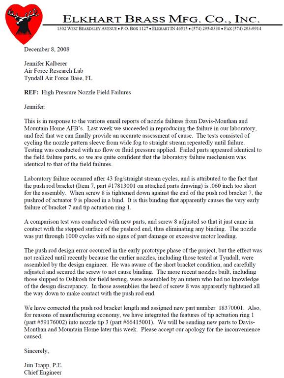
71 63
72 APPENDIX C - Oshkosh Engineering Technical Reports 64
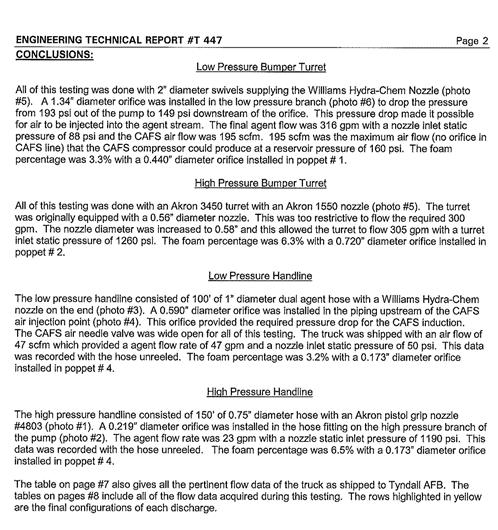
73 65
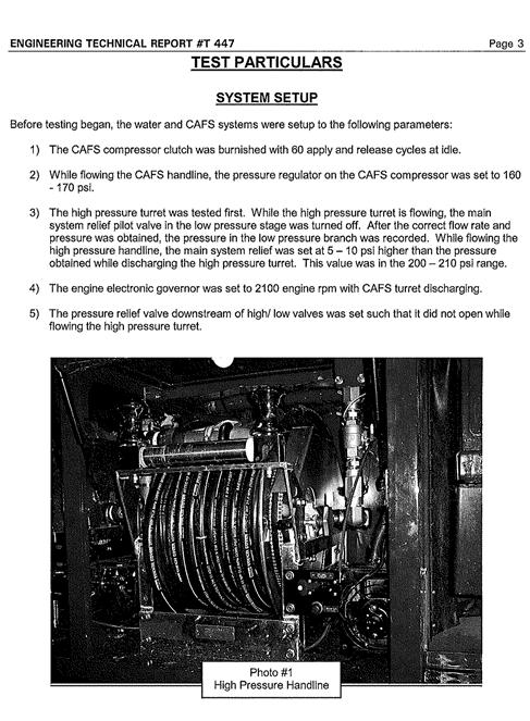
74 66
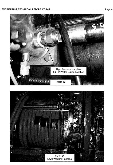
75 67
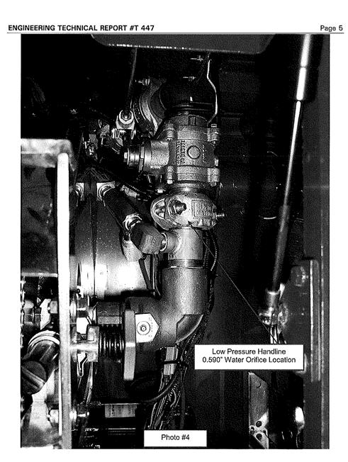
76 68
77 69
78 70
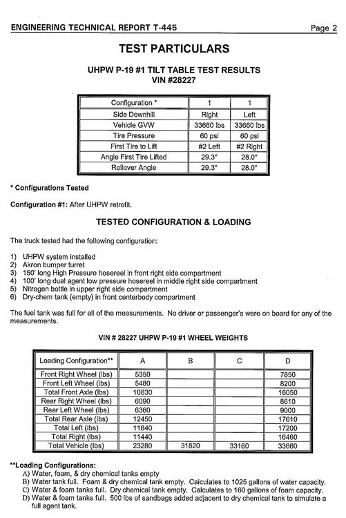
79 71
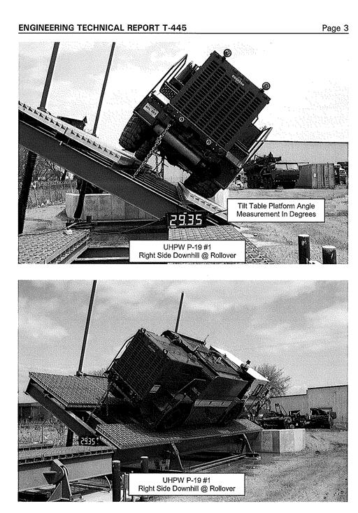
80 72
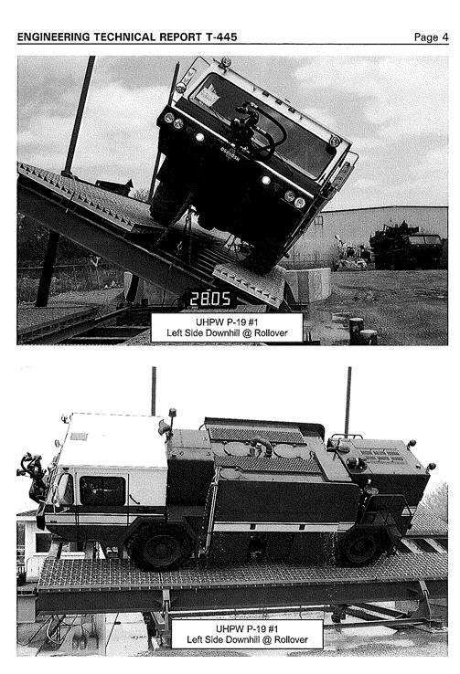
81 73
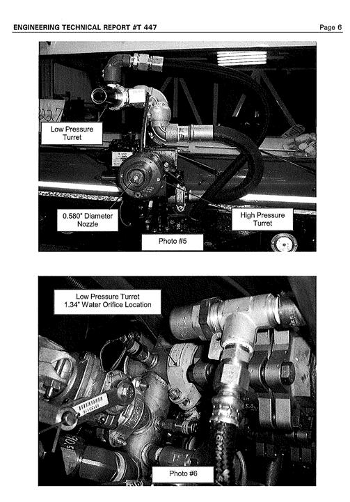
82 74
HALON FLIGHTLINE EXTINGUISHER EVALUATION: DATA SUPPORTING STANDARD DEVELOPMENT [INCLUDES NOVEMBER 2007 ADDENDUM]
![HALON FLIGHTLINE EXTINGUISHER EVALUATION: DATA SUPPORTING STANDARD DEVELOPMENT [INCLUDES NOVEMBER 2007 ADDENDUM]](/thumbs/77/74926656.jpg "HALON FLIGHTLINE EXTINGUISHER EVALUATION: DATA SUPPORTING STANDARD DEVELOPMENT [INCLUDES NOVEMBER 2007 ADDENDUM]") AFRL-RX-TY-TR-2008-4573 HALON FLIGHTLINE EXTINGUISHER EVALUATION: DATA SUPPORTING STANDARD DEVELOPMENT [INCLUDES NOVEMBER 2007 ADDENDUM] John R. Hawk Applied Research Associates P.O. Box 40128 Tyndall
AFRL-RX-TY-TR-2008-4573 HALON FLIGHTLINE EXTINGUISHER EVALUATION: DATA SUPPORTING STANDARD DEVELOPMENT [INCLUDES NOVEMBER 2007 ADDENDUM] John R. Hawk Applied Research Associates P.O. Box 40128 Tyndall
EXTINGUISHMENT AND BURNBACK TESTING OF FIRE FIGHTING AGENTS
 AFRL-ML-TY-TR-2005-4581 EXTINGUISHMENT AND BURNBACK TESTING OF FIRE FIGHTING AGENTS Kimberly D. Barrett Jennifer L. Kalberer Applied Research Associates, Inc. P.O. Box 40128 Tyndall AFB, FL 32403 Interim
REPORT DOCUMENTATION PAGE
 REPORT DOCUMENTATION PAGE Form Approved OMB No. 0704-0188 The public reporting burden for this collection of information is estimated to average 1 hour per response, including the time for reviewing instructions,
MINIMUM PERFORMANCE REQUIREMENT FOR AIR FORCE FLIGHTLINE FIRE EXTINGUISHERS:
 AFRL-ML-TY-TR-02-4540 MINIMUM PERFORMANCE REQUIREMENT FOR AIR FORCE FLIGHTLINE FIRE EXTINGUISHERS: EXTINGUISHING PERFORMANCE AGAINST 3-DIMENSIONAL AND HIDDEN FIRES MAY 2002 Approved for Public Release;
EVALUATION OF FIKE CORPORATION S EXPLOSION SUPPRESSION SYSTEM FOR ULTRA-HIGH SPEED FIRE SUPPRESSION APPLICATIONS
 AFRL-RX-TY-TR-2008-4516 EVALUATION OF FIKE CORPORATION S EXPLOSION SUPPRESSION SYSTEM FOR ULTRA-HIGH SPEED FIRE SUPPRESSION APPLICATIONS John Hawk, PE Applied Research Associates P.O. Box 40128 Tyndall
AFRL-ML-TY-TR
 AFRL-ML-TY-TR-2004-4511 PERFORMANCE EVALUATION OF THE COMBINED AGENT FIRE FIGHTING SYSTEM (CAFFS) September 2003 Jennifer L. Kalberer Michael J. McDonald Kimberly D. Barrett Kristofor S. Cozart Applied
FIRE PROTECTION FOR. Dist A. MILITARY GROUND VEHICLES. Steve McCormick US Army RDECOM-TARDEC.
 FIRE PROTECTION FOR MILITARY GROUND VEHICLES Steve McCormick US Army RDECOM-TARDEC (586) 753-2610 steven.j.mccormick@us.army.mil April 2009 UNCLAS: Approved for public release Report Documentation Page
The Conservation Fund The Center for Conservation and Development
 The Conservation Fund The Center for Conservation and Development Partners in Land and Water Conservation Smart Growth and Sustainable Ranges August 23, 2004 Savannah, GA The Conservation Fund--8/23/04
AFRL-RB-WP-TR
 AFRL-RB-WP-TR-2012-0191 NOVEL HEAT TRANSFER DEVICE RESEARCH Ryan E. Mikus Advanced Structural Concepts Branch Structures Division Kenneth D. Kihm University of Tennessee APRIL 2012 Interim Report See additional
TECHNICAL MANUAL OPERATOR'S, ORGANIZATIONAL AND DIRECT SUPPORT MAINTENANCE MANUAL (INCLUDING REPAIR PARTS AND SPECIAL TOOLS LIST)
") TECHNICAL MANUAL OPERATOR'S, ORGANIZATIONAL AND DIRECT SUPPORT MAINTENANCE MANUAL (INCLUDING REPAIR PARTS AND SPECIAL TOOLS LIST) TRUCK, FIRE FIGHTING, 4x4, MODEL 1350 PKP/200 AFFF NSN 4210-00-484-5729
TECHNICAL MANUAL OPERATOR'S, ORGANIZATIONAL AND DIRECT SUPPORT MAINTENANCE MANUAL (INCLUDING REPAIR PARTS AND SPECIAL TOOLS LIST) TRUCK, FIRE FIGHTING, 4x4, MODEL 1350 PKP/200 AFFF NSN 4210-00-484-5729
Converting Existing Copper Wire Firing System to a Fiber-Optically Controlled Firing System for Electromagnetic Pulsed Power Experiments
 ARL-TN-0863 DEC 2017 US Army Research Laboratory Converting Existing Copper Wire Firing System to a Fiber-Optically Controlled Firing System for Electromagnetic Pulsed Power Experiments by Robert Borys
Force Protection Joint Experiment (FPJE) Battlefield Anti-Intrusion System (BAIS) Sensors Data Analysis and Filtering Metrics
 Battlefield Anti-Intrusion System (BAIS) Sensors Data Analysis and Filtering Metrics") Force Protection Joint Experiment (FPJE) Battlefield Anti-Intrusion System (BAIS) Sensors Data Analysis and Filtering Metrics C.M. Barngrover, R.T. Laird, T.A. Kramer, J.R. Cruickshanks, S.H. Cutler Space
Force Protection Joint Experiment (FPJE) Battlefield Anti-Intrusion System (BAIS) Sensors Data Analysis and Filtering Metrics C.M. Barngrover, R.T. Laird, T.A. Kramer, J.R. Cruickshanks, S.H. Cutler Space
Low Impact Development at Naval Facilities: Opportunities and Constraints
 Low Impact Development at Naval Facilities: Opportunities and Constraints Jim Harris, PE and Khoi Nguyen, PhD, PE Naval Facility Engineering Command Atlantic Sustainability Track 8027 - May 7, 2009 Environment,
Vision Protection From Lasers Overview for Dr. Beagley, Australia
 DISTRIBUTION A: Approved for public release; Distribution is Unlimited. Vision Protection From Lasers Overview for Dr. Beagley, Australia DISTRIBUTION STATEMENT A: Unlimited distribution. Approved for
A Novel Approach for a Hostile Arms Fire Sensor
 UNCLASSIFIED: Dist A. Approved for public release Joseph Rudy Montoya, PhD and Jorge Melchor US Army Research Laboratory-SLAD White Sands Missile Range, NM Venu Siddapureddy and Darryl Bryk US Army RDECOM-TARDEC
AFCEC-CX-TY-TR
 Dr. Mark Enlow Applied Research Associates 430 West 5 th Street, Suite 700 Panama City, FL 32401 AFCEC-CX-TY-TR-2016-0004 Development and Evaluation of a Prototype Wheeled Ultra-High Pressure Extinguisher
ULTRA HIGH PRESSURE FIRE SUPPRESSION SYSTEMS Product Catalog HMAFIRE.COM FIRE
 HMA FIRE ULTRA HIGH PRESSURE FIRE SUPPRESSION SYSTEMS 2018 Product Catalog HMAFIRE.COM 844.855.FIRE HMA FIRE ULTRA HIGH PRESSURE FIRE SUPPRESSION SYSTEMS Roots from Air Force Testing The story of HMA Fire
DURIP: Fast Oscilloscope and Detectors for Air Laser Research
 DURIP: Fast Oscilloscope and Detectors for Air Laser Research Office of Naval Research N14-13-1-683 Principal Investigator Richard Miles Princeton University Department of Mechanical and Aerospace Engineering
Self Expanding Foam Fire Suppression System SPECIFICATION SHEET Rev
 Self Expanding Foam Fire Suppression System SPECIFICATION SHEET Rev 1.0 03-07-2017 Description Self Expanding Foam Systems (SEFS) are the alternative solution to existing flammable and combustible liquid
Industrial Workshop Gettysburg, PA February 26, 2004
 Industrial Workshop Gettysburg, PA February 26, 2004 US Army Corps of Engineers ERDC-CERL Using Air-to-Air Energy Recovery for Industrial Process and Energy Optimization to Comply with 90.1 and Score with
Unattended Radiation Sensor Systems for Remote Terrestrial Applications and Nuclear Nonproliferation
 Unattended Radiation Sensor Systems for Remote Terrestrial Applications and Nuclear Nonproliferation Lodewijk van den Berg, Alan E. Proctor, Ken R. Pohl, Alex Bolozdynya and Raymond DeVito Constellation
Airport Firefighter Recertification Core Competency Task Book
 2011 Airport Firefighter Recertification Core Competency Task Book Agency:_ TASK BOOK ASSIGNED TO: INDIVIDUAL S PRINTED NAME & TITLE 1 2 DO NOT COMPLETE THIS UNLESS YOU ARE RECOMMENDING THE INDIVIDUAL
AFRL-RX-TY-TR
 AFRL-RX-TY-TR-2012-0022 ANALYSIS OF COMMERCIALLY AVAILABLE HELMET AND BOOT OPTIONS FOR THE JOINT FIREFIGHTER INTEGRATED RESPONSE ENSEMBLE (JFIRE) Jennifer L. Schroeder President, Fire Science Solutions,
FIRE HAZARD ASSESSMENT IN SUPPORTING FIRE PROTECTION SYSTEM DESIGN OF A CHEMICAL PROCESS FACILITY ABSTRACT
 FIRE HAZARD ASSESSMENT IN SUPPORTING FIRE PROTECTION SYSTEM DESIGN OF A CHEMICAL PROCESS FACILITY Ali Pezeshk, Joseph Chang, Dwight Hunt, and Peter Jahn Parsons Infrastructure & Technology Group, Inc.
TECHNICAL MANUAL OPERATOR'S, ORGANIZATIONAL AND DIRECT SUPPORT MAINTENANCE MANUAL (INCLUDING REPAIR PARTS AND SPECIAL TOOLS LIST)
") TM 5-4210-228-14&P-2 TECHNICAL MANUAL OPERATOR'S, ORGANIZATIONAL AND DIRECT SUPPORT MAINTENANCE MANUAL (INCLUDING REPAIR PARTS AND SPECIAL TOOLS LIST) TRUCK, FIRE FIGHTING, 4x4, MODEL 1350 PKP/200 AFFF
TM 5-4210-228-14&P-2 TECHNICAL MANUAL OPERATOR'S, ORGANIZATIONAL AND DIRECT SUPPORT MAINTENANCE MANUAL (INCLUDING REPAIR PARTS AND SPECIAL TOOLS LIST) TRUCK, FIRE FIGHTING, 4x4, MODEL 1350 PKP/200 AFFF
ECBC SBIR/STTR Projects. ECBC SBIR/STTR MSCoE STRF Conference
 ECBC SBIR/STTR Projects ECBC SBIR/STTR MSCoE STRF Conference JAMES M. CRESS, JANET L. JENSEN, JAMES O. JENSEN OCTOBER 2012 Report Documentation Page Form Approved OMB No. 0704-0188 Public reporting burden
TECHNICAL MANUAL OPERATOR S, ORGANIZATIONAL, DIRECT SUPPORT AND GENERAL SUPPORT MAINTENANCE MANUAL IINCLUDING REPAIR PARTS AND SPECIAL TOOLS LISTI FOR
 TM 5-4210-222-14&P-3 TECHNICAL MANUAL OPERATOR S, ORGANIZATIONAL, DIRECT SUPPORT AND GENERAL SUPPORT MAINTENANCE MANUAL IINCLUDING REPAIR PARTS AND SPECIAL TOOLS LISTI FOR TRUCK, FIREFIGHTIN6G DRY CHEMICAL
Saskatchewan Evaluation and Certification Guide. Appendix D
 Saskatchewan Evaluation and Certification Guide Appendix D NFPA 1002 Fire Apparatus Driver/Operator Professional Qualifications Revised 2013 Emergency Management and Fire Safety Page 1 of 13 Table of Contents
AIRPORT FIRE FIGHTER ID#: STANDARD:
 4.1 General Requirements Evaluation Sheet: ARFF 4.1.1.4-A 4.1.1.4 General Skill Requirements JPR - HAF - 1 Standard Area: General Skill Requirement Revised 1/27/2017 STANDARD: 4.1.1.4 FAA #3 Rescue Safety
Direct measurement of the aerosol absorption and extinction cross section for a variety of chemical and biological simulants in the LWIR
 Direct measurement of the aerosol absorption and extinction cross section for a variety of chemical and biological simulants in the LWIR Kristan P. Gurton Rachid Dahmani David Ligon Army Research Laboratory,
WILLIAM HICKS. MSc, CFEI, CFPS, IAAI-CFI, MIFireE, EFO, CFOD, F-IAFI. Associate Professor Eastern Kentucky University
 Foam Systems WILLIAM HICKS MSc, CFEI, CFPS, IAAI-CFI, MIFireE, EFO, CFOD, F-IAFI Associate Professor Eastern Kentucky University William.Hicks@eku.edu Objectives Classify high, medium, and lowexpansion
Public Comment No. 3-NFPA [ Chapter 7 ]
![Public Comment No. 3-NFPA [ Chapter 7 ]](/thumbs/92/109131250.jpg "Public Comment No. 3-NFPA [ Chapter 7 ]") Page 1 of 8 Public Comment No. 3-NFPA 405-2013 [ Chapter 7 ] Chapter 7 ARFF Personnel Safety and Safety Management 7.1 Scope. This chapter identifies the knowledge and skills necessary to ensure ARFF personnel
Page 1 of 8 Public Comment No. 3-NFPA 405-2013 [ Chapter 7 ] Chapter 7 ARFF Personnel Safety and Safety Management 7.1 Scope. This chapter identifies the knowledge and skills necessary to ensure ARFF personnel
Fire Suppression Performance of Manually Applied CAF and Other Water Based System
 Fire Suppression Performance of Manually Applied CAF and Other Water Based System Andrew Kim and George Crampton Fire Suppression Research and Applications A Technical Working Conference (SUPDET2012) Outline
AIRCRAFT RESCUE AND FIREFIGHTING
 AIRCRAFT RESCUE AND FIREFIGHTING ICAO/FAA Regional Workshop for Aerodrome Certification Safety Inspectors November 6-8, 2012 ARFF 1 INSPECTING AIRCRAFT RESCUE AND FIREFIGHTING (ARFF) Tools, records, knowledge
Recent Advances in Mercuric Iodide Detector Fabrication and Instrument Development*
 Recent Advances in Mercuric Iodide Detector Fabrication and Instrument Development* Lodewijk van den Berg and Steven W. Pauly Constellation Technology Corp., 7887 Bryan Dairy Road, Suite 100, Largo, FL
SECURITY BLANKET Foam Fire Protection Products
 SECURITY BLANKET Foam Fire Protection Products REAL DANGERS DEMAND REAL SOLUTIONS If your business manufactures, stores, or transports flammable liquids, the thought of a devastating fire always burns
Design Considerations for Abrasive Blast Rooms & Recovery Systems
 Clemco Industries Corp. presents Design Considerations for Abrasive Blast Rooms & Recovery Systems by Bob Kerr Business Development Manager Report Documentation Page Form Approved OMB No. 0704-0188 Public
FIRE PROTECTION BUREAU ACCREDITATION AND CERTIFICATION PO Box Olympia WA (360) FAX: (360) AIRPORT FIREFIGHTER
 FAX: (360) AIRPORT FIREFIGHTER") 5.2 RESPONSE 5.2.1 Responding to Incidents Daytime Evaluation Sheets: 5.2.1; 5.3.6 Skill Sheet: A Birth STANDARD: 5.2.1 and 5.3.6 TASK: Respond to a daytime incident or accident on and adjacent to the
5.2 RESPONSE 5.2.1 Responding to Incidents Daytime Evaluation Sheets: 5.2.1; 5.3.6 Skill Sheet: A Birth STANDARD: 5.2.1 and 5.3.6 TASK: Respond to a daytime incident or accident on and adjacent to the
TWO TIMES THE FIGHT Twin-Agent Fire Suppression Systems
 TWO TIMES THE FIGHT Twin-Agent Fire Suppression Systems A TOUGH SOLUTION FOR TOUGH FIRES No fire should be taken lightly. Yet, there are some that go far beyond a typical fire. These extremely hazardous
6 th Pipeline Technology Conference 2011
 6 th Pipeline Technology Conference 2011 Pipeline Leak Detection and Theft Detection Using Rarefaction Waves Authors: Dr Alex Souza de Joode, VP International Operations; ATMOS International, UK. Andrew
When it Really Matters
 When it Really Matters 1 CURRENT TOOLS OF THE TRADE Crash Rescue Equipment Service, Inc. Dallas, Texas ARFF vehicles have evolved to provide safe, rapid response to get agent transported from the fire
C-NRPP Quality Assurance Guidance for Radon Test Devices
 C-NRPP Quality Assurance Guidance for Radon Test Devices Table of Contents: 1. Purpose 2. Definitions 3. Quality Assurance Plan 4. Calibration 5. Spikes/Performance Tests 6. Duplicates 7. Blanks 8. Cross-Checks
NOTICE AND SIGNATURE PAGE
 DISCLAIMER Reference herein to any specific commercial product, process, or service by trade name, trademark, manufacturer, or otherwise does not constitute or imply its endorsement, recommendation, or
Distribution Restriction Statement
 DEPARTMENT OF THE ARMY ETL 1110-3-485 U.S. Army Corps of Engineers CEMP-ET Washington, D.C. 20314-1000 Technical Letter No. 1110-3-485 15 October 1997 Engineering and Design FIRE PROTECTION FOR HELICOPTER
Driver/Operator ARFF
 National Certification Program Study Guide March 2010 Driver/Operator ARFF NFPA 1002, Standard for Fire Appratus Driver/Operator Professional Qualifications, 2009 Edition This document is provided at no
Class Outline NFPA 1003/ProBoard Basic Aircraft Rescue Firefighting
 Class Outline NFPA 1003/ProBoard Basic Aircraft Rescue Firefighting Class Length: 5 days (M-F), 40 hours Class Times: (M-Th) 0800-1300 (F) Reading Materials: IFSTA- Aircraft Rescue and Firefighting, 5
Required Materials For complete material(s) information, refer to
 information, refer to") Butler Community College Health, Education, and Public Safety Division Troy R. Jellison Revised Fall 2018 Implemented Spring 2019 COURSE OUTLINE Firefighter 1 Course Description FS 100. Firefighter 1.
Butler Community College Health, Education, and Public Safety Division Troy R. Jellison Revised Fall 2018 Implemented Spring 2019 COURSE OUTLINE Firefighter 1 Course Description FS 100. Firefighter 1.
High-Reach Extendable Turrets With Skin-Penetrating Nozzle
 DOT/FAA/AR-05/53 Office of Aviation Research and Development Washington, D.C. 20591 High-Reach Extendable Turrets With Skin-Penetrating Nozzle November 2005 Final Report This document is available to the
Distribution Restriction Statement
 DEPARTMENT OF THE ARMY U.S. Army Corps of Engineers CEMP-ET Washington, DC 20314-1000 ETL 1110-3-489 Technical Letter No. 1110-3-489 3 April 1998 Engineering and Design DOMESTIC WATER HEATERS FOR BARRACKS
REQUIREMENTS. For FIRE DEPARTMENTS. State of West Virginia. Bob Wise Governor THE DEPARTMENT OF MILITARY AFFAIRS AND PUBLIC SAFETY
 REQUIREMENTS For FIRE DEPARTMENTS State of West Virginia Bob Wise Governor THE DEPARTMENT OF MILITARY AFFAIRS AND PUBLIC SAFETY Joe Martin Secretary West Virginia State Fire Commission 1207 Quarrier St.,
TIME TO PRIME, by Rich Teske
 TIME TO PRIME, by Rich Teske Fire pump design on motorized vehicles experienced a radical change starting as early as 1912. That was when the basic fire pump designs started to change over from the positive
Based on NFPA 1003: Standard for Airport Fire Fighter Professional Qualifications 2015 Edition
 Based on NFPA 1003: Standard for Airport Fire Fighter Professional Qualifications 2015 Alabama Fire College Airport Firefighter Instructional JPR Verification Sheet Full Name: Fire Department: This Instructional
1.1. SYSTEM MODELING
 1 INTRODUCTION Electro-optical imaging system analysis is a mathematical construct that provides an optimum design through appropriate trade studies. A comprehensive model includes the target, background,
SPECIALISTS IN INDUSTRIAL PROTECTION
 SPECIALISTS IN INDUSTRIAL PROTECTION commitment PASSION FOR EXCELLENCE KME Works for You. As a privately held family company since 1946, KME is truly a success story. We ve experienced six decades of steady
Sustainability Criteria for Planning, Constructing, and Operating Contingency Bases
 Sustainability Criteria for Planning, Constructing, and Operating Contingency Bases Giselle Rodriguez, P.E. Civil and Environmental Engineer Construction Engineering Research Laboratory Engineer Research
ANSI/AHRI Standard 620 (I-P) 2014 Standard for Performance Rating of Self-contained Humidifiers for Residential Applications
 2014 Standard for Performance Rating of Self-contained Humidifiers for Residential Applications") ANSI/AHRI Standard 620 (I-P) 2014 Standard for Performance Rating of Self-contained Humidifiers for Residential Applications Approved by ANSI on 19 November 2014 IMPORTANT SAFETY DISCLAIMER AHRI does not
ANSI/AHRI Standard 620 (I-P) 2014 Standard for Performance Rating of Self-contained Humidifiers for Residential Applications Approved by ANSI on 19 November 2014 IMPORTANT SAFETY DISCLAIMER AHRI does not
Amerex Fire Suppression Systems. Because Operators and the Environment are NOT Disposable Quality is Behind the Diamond.
 Amerex Fire Suppression Systems Because Operators and the Environment are NOT Disposable Quality is Behind the Diamond. Quality is Behind the Diamond. Diamonds have long been a symbol for quality. At Amerex
NTC THERMISTOR SENSOR PERFORMANCE
 NTC THERMISTOR SENSOR PERFORMANCE Accuracy, Interchangeability, Beta Tolerance, Tolerance Comparison, Stability, Drift, and Moisture Induced Failure When designing the best temperature probe for a specific
Conceptual Design of a Better Heat Pump Compressor for Northern Climates
 Purdue University Purdue e-pubs International Compressor Engineering Conference School of Mechanical Engineering 1976 Conceptual Design of a Better Heat Pump Compressor for Northern Climates D. Squarer
WHITE PAPER. ANSI/AHRI Standard for Fan and Coil Evaporators - Benefits and Costs
 Abstract Fan and coil evaporators as used in the industrial refrigeration industry can be certified for performance per ANSI/AHRI Standard 420-2008, Performance Rating of Forced-Circulation Free-Delivery
DEPARTMENTAL GUIDELINES CHAPTER 6 TACTICAL OPERATIONS
 Section 400.000 Suppression Systems The purpose of this guide is to assist the Incident Commander (IC), Fire Officers and Firefighters with the planning of effective operations for supporting water-based
ARKANSAS FIRE PROTECTION LICENSING BOARD ACT 743 OF 1977
 ARKANSAS FIRE PROTECTION LICENSING BOARD ACT 743 OF 1977 As Amended July 1, 1999 20-22-601. LEGISLATIVE INTENT FIRE PROTECTION LICENSING BOARD It is the purpose and intent of this subchapter to provide
OWNER'S SERVICE MANUAL NO INSPECTION, MAINTENANCE AND RECHARGE
 FOAM FIRE EXTINGUISHERS MODEL 254-6 LITER AFFF FOAM WITH SPRAY NOZZLE Model 250 2 ½ GAL.LON AFFF FOAM WITH ASPIRATED NOZZLE MODEL 252 2 ½ GAL.LON FFFP (ALCOHOL RESISTANT) FOAM WITH ASPIRATED NOZZLE OWNER'S
Subchapter 7. General Industry Safety Orders Group 27. Fire Protection Article 157. Portable Fire Extinguishers. Return to index New query
 This information is provided free of charge by the Department of Industrial Relations from its web site at www.dir.ca.gov. These regulations are for the convenience of the user and no representation or
Chapter 17 Test. Directions: Write the correct letter on the blank before each question.
 Chapter 17 Test Name: Date: Directions: Write the correct letter on the blank before each question. Objective 1: Describe initial factors to consider when suppressing structure fires. 1. Which strategy
Twin-Agent Fire Fighting/Securing Systems Specifications
 Twin-Agent Fire Fighting/Securing Systems Specifications Models 450/50, 450/100, 900/100 & 1350/200 INDEX 1.0 GENERAL 1.1 References 1.2 Submittals 1.3 System Capabilities 1.4 Quality Control 1.5 Warranty,
A.U.P.C.I ASOCIACIÓN URUGUAYA DE PROTECCION CONTRA INCENDIO AUPCI
 A.U.P.C.I ASOCIACIÓN URUGUAYA DE PROTECCION CONTRA INCENDIO Foam Overview Applications Flammable Liquid Storage Tanks Diked Storage Tanks Loading Racks/Transfer Stations Closed Head Sprinkler Systems Deluge
Foam Systems U.S. Quick Reference Guide
 Foam Systems U.S. Quick Reference Guide This guide is intended for general reference only. Prior to the design, layout, and/or installation of any sprinkler system, please refer to Viking s technical documentation
ANSUL. Twin-Agent Fire Fighting/Securing Systems Specifications. Models 450/50-B, 450/100-B, 900/100-B INDEX SPECIFICATIONS
 ANSUL Twin-Agent Fire Fighting/Securing Systems Specifications Models 450/50-B, 450/100-B, 900/100-B INDEX 1.0 GENERAL 1.1 References 1.2 Submittals 1.3 System Capabilities 1.4 Quality Control 1.5 Warranty,
SUBJECT FIRE OPERATIONS GUIDELINE (F.O.G.) #F510 Issued: 1/2014 Last Revision: 1/2014 Pages: 9 By Order Of: J.S. Thompson, Fire Chief
 #F510 Issued: 1/2014 Last Revision: 1/2014 Pages: 9 By Order Of: J.S. Thompson, Fire Chief") THE COLONY FIRE DEPARTMENT FIRE OPERATIONS GUIDELINE SUBJECT FIRE OPERATIONS GUIDELINE (F.O.G.) #F510 Issued: 1/2014 Last Revision: 1/2014 Pages: 9 By Order Of: J.S. Thompson, Fire Chief Review Reviewed
THE COLONY FIRE DEPARTMENT FIRE OPERATIONS GUIDELINE SUBJECT FIRE OPERATIONS GUIDELINE (F.O.G.) #F510 Issued: 1/2014 Last Revision: 1/2014 Pages: 9 By Order Of: J.S. Thompson, Fire Chief Review Reviewed
The 2012 Fire Suppression Rating Schedule (FSRS)
") The 2012 Fire Suppression Rating Schedule (FSRS) Summary of Changes March 21, 2017 How to Get a Copy of the FSRS Only FIRE CHIEFS may request a free copy of the FSRS. Submit (via e-mail only) an ATTACHED
The 2012 Fire Suppression Rating Schedule (FSRS) Summary of Changes March 21, 2017 How to Get a Copy of the FSRS Only FIRE CHIEFS may request a free copy of the FSRS. Submit (via e-mail only) an ATTACHED
NISH Report: Team Catalyst Paper Folding Machine
 1 : Team Catalyst Paper Folding Machine ABSTRACT Ohio University s Team Catalyst was given a task to find a customer who was physically or mentally handicapped and required further assistance in order
SECTION WET-PIPE SPRINKLER SYSTEMS
 SECTION 21 13 13 WET-PIPE SPRINKLER SYSTEMS PART 1 - GENERAL 1.1 SCOPE OF WORK A. Design, installation and testing shall be in accordance with NFPA 13 except for specified exceptions. B. The demolition
ENERGY EFFICIENCY PROJECTS. NO-COST AND LOW-COST UPGRADES FOR YOUR FACILITY In partnership with: Refrigerating Engineers & Technicians Association
 ENERGY EFFICIENCY PROJECTS NO-COST AND LOW-COST UPGRADES FOR YOUR FACILITY In partnership with: Refrigerating Engineers & Technicians Association INTRODUCTION Save Money, Improve Operations Today s refrigeration
Incident Symbology Framework, Guideline, and Operational Implementation Guidance Version 2.0
 Produced in partnership with Ardent Management Consulting and with support from: HSHQDC-14-F-00048 Incident Symbology Framework, Guideline, and Operational Implementation Guidance Version 2.0 I. Guideline
API MANUAL OF PETROLEUM MEASUREMENT STANDARDS
 API MANUAL OF PETROLEUM MEASUREMENT STANDARDS Chapter 22 Testing Protocols Section 1 General Guidelines for Developing Testing Protocols for Devices Used in the Measurement of Hydrocarbon Fluids Type Testing
Town of Whitby By-law #
 Town of Whitby By-law # 7263-17 Fire Department Establishing and Regulating By-law Being a By-law to Establish and Regulate the Fire Department, and to Repeal By-law # s. 4202-98, 6078-08 and 6834-14.
Chapter 1 Introduction
 Chapter 1 Introduction This chapter presents an introductory background to the research work undertaken, the problem statement, research issues involved and objectives of the research work. The contribution
AMADOR FIRE PROTECTION DISTRICT
 SUMMARY DESCRIPTION: Class specifications are intended to present a descriptive list of the range of duties performed by the employees in the class. Specifications are not intended to reflect all duties
COUNTY OF BERGEN DEPARTMENT OF PUBLIC SAFETY LAW AND PUBLIC SAFETY INSTITUTE POLICE, FIRE & EMS ACADEMIES 281 Campgaw Road Mahwah, N.J.
 COUNTY OF BERGEN DEPARTMENT OF PUBLIC SAFETY LAW AND PUBLIC SAFETY INSTITUTE POLICE, FIRE & EMS ACADEMIES 281 Campgaw Road Mahwah, N.J. 07430 (201)785-6000 Police FAX (201)785-6036 Fire FAX (201)785-6036
Project Number: P15441
 Multidisciplinary Senior Design Kate Gleason College of Engineering Rochester Institute of Technology Rochester, New York 14623 Project Number: P15441 MINI-AIR: PERSONAL COOLING DEVICE Alexander Cornell
Australian Standard. Water mist fire protection systems System design, installation and commissioning AS
 AS 4587 1999 Australian Standard Water mist fire protection systems System design, installation and commissioning This Australian Standard was prepared by Committee FP/12, Aqueous Fire Protection Systems.
J. R. Qualey III, L. Desmarais, J. Pratt Simplex Time Recorder Co., 100 Simplex Drive, Westminster, MA 01441
 J. R. Qualey III, L. Desmarais, J. Pratt Simplex Time Recorder Co., 100 Simplex Drive, Westminster, MA 01441 Response-Time Comparisons of Ionization and Photoelectric/Heat Detectors 1. Introduction Despite
USER APPROVAL OF SAFETY INSTRUMENTED SYSTEM DEVICES
 USER APPROVAL OF SAFETY INSTRUMENTED SYSTEM DEVICES Angela E. Summers, Ph.D., P.E, President Susan Wiley, Senior Consultant SIS-TECH Solutions, LP Process Plant Safety Symposium, 2006 Spring National Meeting,
A.C.A. Tit. 20, Subtit. 2, Ch. 22, Subch. 6 Note
 A.C.A. Tit. 20, Subtit. 2, Ch. 22, Subch. 6 Note Arkansas Code of 1987 Annotated Official Edition 1987-2014 by the State of Arkansas All rights reserved. *** Legislation is current through the 2013 Regular
HIGH-RISE RETROFIT ORDINANCES - NO and NO
 INFORMATION BULLETIN / PUBLIC - BUILDING CODE REFERENCE NO.: LAMC 91.8604 Effective: 9-06-90 DOCUMENT NO. P/BC 2002-054 Revised: 4-15-03 Previously Issued As: MGD 88 HIGH-RISE RETROFIT ORDINANCES - NO.
Design and Evaluation of a Wildfire Sprinkler
 Design and Evaluation of a Wildfire Sprinkler September 2017 Roy Campbell Technical report no. 53 Wildfire Operational Research Group http://wildfire.fpinnovations.ca/ fpinnovations.ca FPInnovations is
FUNCTIONAL SAFETY IN FIRE PROTECTION SYSTEM E-BOOK
 FUNCTIONAL SAFETY IN FIRE PROTECTION SYSTEM E-BOOK USEFUL TERMINOLOGY BASIC PROCESS CONTROL SYSTEM (BPCS) System which responds to input signals from the process, its associated equipment, other programmable
POWERFUL CUSTOMIZED SOLUTIONS UNMATCHED QUALITY
 Vactor celebrates over 45 years as your powerful sewer cleaning partner. For nearly 50 years, Vactor Manufacturing has been the leader in building combination sewer cleaners with technological innovation
Based on NFPA 1001: Standard for Fire Fighter Professional Qualifications, 2013 Edition.
 Based on NFPA 1001: Standard for Fire Fighter Professional Qualifications, 2013 Edition. Revised 02/10/2017 Alabama Fire College Firefighter II Instructional JPR Verification Sheet Full Name: Fire Department:
The Next Generation of Foam Fire Suppression. Automatic CAF Fire hose reel system FEATURES
 Fire hose reel system The first automatic CAF, fire hose reel system FEATURES The Automatic CAF Fire Hose Systems are ideal for firefighting needs in locations that require foam as a fire fighting agent.
GUIDELINES FOR THE APPROVAL OF HELICOPTER FACILITY FOAM FIRE-FIGHTING APPLIANCES
 E 4 ALBERT EMBANKMENT LONDON SE1 7SR Telephone: +44 (0)20 7735 7611 Fax: +44 (0)20 7587 3210 GUIDELINES FOR THE APPROVAL OF HELICOPTER FACILITY FOAM FIRE-FIGHTING APPLIANCES MSC.1/Circ.1431 31 May 2012
AS Australian Standard. Portable fire extinguishers Guide to servicing. This is a free 7 page sample. Access the full version online.
 AS 3676 1989 Australian Standard Portable fire extinguishers Guide to servicing This Australian Standard was prepared by Committee FP/3, Fire Extinguishers. It was approved on behalf of the Council of
2017 Annual Report. King County Fire District No. 27 Fall City, WA
 2017 Annual Report King County Fire District No. 27 Fall City, WA Foreword Beginning in 2006, the District began collecting the detailed data elements necessary to develop and publish an annual report
HOW IT RELATES TO PERFORMANCE IN REFRIGERATED COMPRESSED AIR DRYERS
 ENERGY CONSUMPTION HOW IT RELATES TO PERFORMANCE IN REFRIGERATED COMPRESSED AIR DRYERS Introduction Those in charge of specifying and purchasing equipment for industrial compressed air systems have many
Foam Solutions, LLC Performance Parkway, Columbus, Ohio Ph ; Fax
 Foam Solutions, LLC 2251 Performance Parkway, Columbus, Ohio 43207 Ph 614-586-1326; Fax 614-586-1278 Foam Proportioner Test Manual Aqua Foam Test Method U.S. Patent 7,080,694/7,513,315. Other patents pending
Failure Modes, Effects and Diagnostic Analysis
 Failure Modes, Effects and Diagnostic Analysis Project: Detcon FP-700 Combustible Gas Sensor Customer: Detcon The Woodlands, TX USA Contract No.: DC 06/08-04 Report No.: DC 06/08-04 R001 Version V1, Revision
NORTHWESTERN UNIVERSITY PROJECT NAME JOB # ISSUED: 03/29/2017
 SECTION 21 0800 - COMMISSIONING OF FIRE SUPPRESSION SYSTEMS GENERAL 1.1 SUMMARY General 1. Work under this contract shall meet the requirements of Division 01, General Requirements, Conditions of Contract,
Technical Article. Foam Systems - Low Expansion, Medium Expansion, High Expansion. Martin Workman, Product Manager Special Hazards Division
 Technical Article Foam Systems - Low Expansion, Medium Martin Workman, Product Manager Special Hazards Division March, 2006 Worldwide Fire Protection www.vikingcorp.com TABLE OF CONTENTS DEFINITION - FOAM
SOUTHERN AFRICAN EMERGENCY SERVICES INSTITUTE NPC Registration No. 2014/162285/08. Interior Industrial Fire Brigade Member- NFPA 1081, 2007
 SOUTHERN AFRICAN EMERGENCY SERVICES INSTITUTE NPC Registration No. 2014/162285/08 Contact Details: Phone: 011-660 5672 Fax2Email: 086 544 0008 Fax: 011 660 1887 Email: info@saesi.com Website: www.saesi.com