Rosemount 3144P Temperature Transmitter with HART Protocol
|
|
|
- Matthew Wade
- 6 years ago
- Views:
Transcription
1 Quick Installation Guide Rosemount 3144P Rosemount 3144P Temperature Transmitter with HART Protocol Start Step 1: Configure (Bench Calibration) Step 2: Verify Configuration Step 3: Set the Switches Step 4: Mount the Transmitter Step 5: Wire and Apply Power Step 6: Perform a Loop Test Safety Instrumented Systems Product Certifications End e
2 Rosemount 3144P Quick Installation Guide 2011 Rosemount Inc. All rights reserved. All marks property of owner. The Emerson logo is a trade mark and service mark of Emerson Electric Co. Rosemount and Rosemount logotype are registered trademarks of Rosemount Inc. HART is a registered trademark of the HART Communications Foundation. Emerson Process Management Rosemount Division 8200 Market Boulevard Chanhassen, MN USA T (US) (800) T (Intnl) (952) F (952) Emerson Process Management Temperature GmbH Frankenstrasse Karlstein Germany T 49 (6188) F 49 (6188) Emerson Process Management Asia Pacific Private Limited 1 Pandan Crescent Singapore T (65) F (65) IMPORTANT NOTICE This installation guide provides basic guidelines for the Rosemount 3144P. It does not provide instructions for detailed configuration, diagnostics, maintenance, service, troubleshooting, Explosion-proof, Flameproof, or intrinsically safe (I.S.) installations. Refer to the 3144P reference manual (document number ) for more instruction. The manual and this QIG are also available electronically on WARNING Explosions could result in death or serious injury: Installation of this transmitter in an explosive environment must be in accordance with the appropriate local, national, and international standards, codes, and practices. Please review the approvals section of this manual for any restrictions associated with a safe installation. In an Explosion-proof/Flameproof installation, do not remove the transmitter covers when power is applied to the unit. Process leaks may cause harm or result in death Install and tighten thermowells or sensors before applying pressure. Do not remove the thermowell while in operation. Electrical shock can result in death or serious injury Avoid contact with the leads and terminals. High voltage that may be present on leads can cause electrical shock. 2
3 Quick Installation Guide Rosemount 3144P STEP 1: CONFIGURE (BENCH CALIBRATION) The Rosemount 3144P communicates using a Field Communicator (communication requires a loop resistance between 250 and 1100 ohms) or AMS. Do not operate when power is below 12 Vdc at the transmitter terminal. Refer to the 3144P Reference Manual (document number ) and Field Communicator Reference Manual (document number ) for more information. Update the Field Communicator Software The Field Communicator Field Device Revision Dev v6, DD v2 or greater is required to fully communicate with the 3144P. The Device Descriptors are available with new communicators at or can be loaded into existing communicators at any Emerson Process Management Service Center. Perform the following steps to determine if an upgrade is required. Refer to Figure Connect the sensor (see the wiring diagram located on the inside of the housing cover). 2. Connect the bench power supply to the power terminals ( + or ). 3. Connect a Field Communicator to the loop across a loop resistor or at the power/signal terminals on the transmitter. 4. The following message will appear if the communicator has a previous version of the device descriptors (DDs). NOTICE: Upgrade the communicator software to access new XMTR functions. Continue with old description? NOTE: If this notice does not appear, the latest DD is installed. If the latest version is not available, the communicator will communicate properly, but when the transmitter is configured some new capabilities may not be visible. To prevent this from happening, upgrade to the latest DD or answer NO to the question and default to the generic transmitter functionality. Figure 1. Connecting a Communicator to a Bench Loop. Power/Signal Terminals 250 R L 1100 Power Supply 3

4 Rosemount 3144P Quick Installation Guide STEP 2: VERIFY CONFIGURATION The Traditional Interface Fast Key Sequences in Table 1 and Device Dashboard Fast Key Sequences in Table 2 may be used for transmitter configuration and startup. Field Communicator User Interface The Traditional Interface - Device Revision 6 and DD Revision 2 Fast Key Sequences can be found on Table 1 on page 5. Figure 2. Traditional Interface - Device Revision 6 and DD Revision 2 The Device Dashboard - Device Revision 6 and DD Revision 3 Fast Key Sequence can be found on Table 2 on page 7. Figure 3. Device Dashboard - Device Revision 6 and DD Revision 3 4
5 Quick Installation Guide Rosemount 3144P Table 1. Traditional Interface - Device Revision 6 and DD Revision 2 Fast Key Sequences Function Fast Key Sequence Active Calibrator 1, 2, 2, 1, 3 Alarm Values 1, 3, 4, 2, 1 Analog Output 1, 1, 4 Average Temperature Setup 1, 3, 3, 2 Average Temperature Configuration 1, 3, 3, 2 Burst Mode 1, 3, 4, 3, 3 Burst Option 1, 3, 4, 3, 4 Calibration 1, 2, 2 Clear Log 1, 2, 1, 6 Configure Hot Backup 1, 3, 3, 4 Configuration 1, 3 D/A Trim 1, 2, 2, 2 Damping Values 1, 3, 4, 1, 3 Date 1, 3, 5, 2 Descriptor 1, 3, 5, 3 Device Information 1, 3, 5 Diagnostics and Service 1, 2 Differential Temperature Setup 1, 3, 3, 1 Differential Temperature Configuration 1, 3, 3, 1 Drift Alert 1, 3, 3, 5 Filter 50/60 Hz 1, 3, 6, 1 First Good Temperature Setup 1, 3, 3, 3 First Good Temperature Configuration 1, 3, 3, 3 Hardware Revision 1, 4, 1 Hart Output 1, 3, 4, 3 Intermittent Sensor Detect 1, 3, 6, 2 Intermittent Threshold 1, 3, 6, 3 Loop Test 1, 2, 1, 1 LRV (Lower Range Value) 1, 3, 4, 1, 1 LSL (Lower Sensor Limit) 1, 3, 4, 1, 5 Master Reset 1, 2, 1, 3 Message 1, 3, 5, 4 Meter Options 1, 3, 4, 4 Open Sensor Holdoff 1, 3, 6, 4 Percent Range 1, 1, 5 Poll Address 1, 3, 4, 3, 1 Process Temperature 1, 1 Process Variables 1, 1 Range Values 1, 3, 4, 1 Review 1, 4 Scaled D/A Trim 1, 2, 2, 3 5
6 Rosemount 3144P Quick Installation Guide Function Fast Key Sequence Sensor 1 Configuration 1, 3, 2, 3 Sensor 2 Configuration 1, 3, 2, 4 Sensor Limits 1, 3, 2, 2 Sensor 1 Serial Number 1, 3, 2, 3, 3 Sensor 2 Serial Number 1, 3, 2, 4, 3 Sensor 1 Setup 1, 3, 2, 3 Sensor 2 Setup 1, 3, 2, 4 Sensor Trim 1, 2, 2, 1, 1 Sensor Type 1, 3, 2, 1 Sensor 1 Unit 1, 3, 2, 3, 1 Sensor 2 Unit 1, 3, 2, 4, 1 Software Revision 1, 4, 1 Status 1, 2, 1, 4 Tag 1, 3, 5, 1 Terminal Temperature Setup 1, 3, 2, 5 Test Device 1, 2, 1 Transmitter-Sensor Matching 1, 3, 2, 1 URV (Upper Range Value) 1, 3, 4, 1, 2 USL (Upper Sensor Limit) 1, 3, 4, 1, 6 Variable Mapping 1, 3, 1 View Log 1, 2, 1, 5 Wires 1, 3, 2, 1 2-wire Offset Sensor 1 1, 3, 2, 3, 6 2-wire Offset Sensor 2 1, 3, 2, 4, 6 Input/Verify Callendar Van-Dusen Constants If Transmitter-Sensor Matching is being used with this combination of a transmitter and sensor, verify the constants input. When using two sensors, repeat Steps 1 5 for the second sensor. 1. At the Home screen, select 1 Device Setup, 3 Configuration, 2 Sensor Config, 1 Change Type/Conn., 1 Sensor 1 (Select Sensor 2 two sensors). Set the control loop to manual. Select OK. 2. Select Cal VanDusen at the Enter Sensor Type prompt. 3. Select the appropriate number of wires at the Enter Sensor Connection prompt. 4. Enter the R o, Alpha, Beta, and Delta values from the stainless steel tag attached to the special-order sensor. 5. Select OK after you return the control loop to automatic control. 6
7 Quick Installation Guide Rosemount 3144P Table 2. Device Dashboard - Device Revision 6 and DD Revision 3 Fast Key Sequences Function Fast Key Sequence Alarm Values 2, 2, 5, 6 Analog Output 2, 2, 5 Average Temperature Setup 2, 2, 3, 2 Burst Mode 2, 2, 8, 3 Burst Option 2, 2, 8, 4 Configure Hot Backup 2, 2, 4, 1, 3 Date 2, 2, 7, 1, 2 Descriptor 2, 2, 7, 1, 3 Device Information 2, 2, 7, 1 Differential Temperature Setup 2, 2, 3, 1 Drift Alert 2, 2, 4, 2 Filter 50/60 Hz 2, 2, 7, 5, 1 First Good Temperature Setup 2, 2, 3, 3 Hardware Revision 1, 8, 9, 3 Intermittent Sensor Detect 2, 2, 4, 2, 1 Intermittent Threshold 2, 2, 4, 2, 2 Loop Test 3, 5, 1 LRV (Lower Range Value) 2, 2, 5, 5, 3 Message 2, 2, 7, 1, 4 Open Sensor Holdoff 2, 2, 7, 4 Percent Range 2, 2, 5, 4 Sensor 1 Configuration 2, 2, 1 Sensor 2 Configuration 2, 2, 2 Sensor 1 Serial Number 2, 2, 1, 7 Sensor 2 Serial Number 2, 2, 2, 7 Sensor 1 Setup 2, 2, 1 Sensor 2 Setup 2, 2, 2 Sensor 1 Type 2, 2, 1, 2 Sensor 2 Type 2, 2, 2, 2 Sensor 1 Unit 2, 2, 1, 4 Sensor 2 Unit 2, 2, 2, 4 Software Revision 1, 8, 9, 4 Tag 2, 2, 7, 1, 1 Terminal Temperature Units 2, 2, 7, 3 URV (Upper Range Value) 2, 2, 5, 5, 2 Variable Mapping 2, 2, 8, 5 2-wire Offset Sensor 1 2, 2, 1, 5 2-wire Offset Sensor 2 2, 2, 2, 5 Input/Verify Callendar Van-Dusen Constants If Transmitter-Sensor Matching is being used with this combination of a transmitter and sensor, verify the constants input. When using two sensors, repeat Steps 1 4 for the second sensor. 1. At the Home screen, select 2 Configure, 2 Manual Setup, 1 Sensor 1 (Select Sensor 2 two sensors). Select Sensormatching-CVD. Set the control loop to manual. Select OK. 2. Enter the R o, Alpha, Beta, and Delta values from the stainless steel tag attached to the special-order sensor. 3. Select OK after you return the control loop to automatic control. 7
8 Rosemount 3144P Quick Installation Guide STEP 3: SET THE SWITCHES The Security and Failure Mode Switches are located on the top center of the electronics module. Follow the steps below to set the switches. Without a LCD Display 1. Set the loop to manual (if applicable) and disconnect the power. 2. Remove the electronics housing cover. 3. Set the switches to the desired position. Reattach housing cover. 4. Apply power and set the loop to automatic control. With a LCD Display 1. Set the loop to manual (if applicable) and disconnect the power. 2. Remove the electronics housing cover. 3. Unscrew the LCD display screws and slide the meter straight off. 4. Set the switches to the desired position. 5. Reattach the LCD display and electronics housing cover (consider LCD display orientation rotate in 90 degree increments). 6. Apply power and set the loop to automatic control. STEP 4: MOUNT THE TRANSMITTER Mount the transmitter at a high point in the conduit run to prevent moisture from draining into the transmitter housing. Typical Field Mount Installation 1. Mount the thermowell to the process container wall. Install and tighten thermowells. Perform a leak check. 2. Attach any necessary unions, couplings, and extension fittings. Seal the fitting threads with an approved thread sealant, such as silicone or PTFE tape (if required). 3. Screw the sensor into the thermowell or directly into the process (depending on installation requirements). 4. Verify all sealing requirements. 5. Attach the transmitter to the thermowell/sensor assembly. Seal all threads with an approved thread sealant, such as silicone or PTFE tape (if required). 6. Install field wiring conduit into the open transmitter conduit entry (for remote mounting) and feed wires into the transmitter housing. 7. Pull the field wiring leads into the terminal side of the housing. 8. Attach the sensor leads to the transmitter sensor terminals (the wiring diagram is located inside the housing cover). 9. Attach and tighten both transmitter covers. A B C A = Thermowell B = Extension (Nipple) C = Union or Coupling E D D = Conduit for Field Wiring (dc power) E = Extension Fitting Length 8
9 Quick Installation Guide Rosemount 3144P STEP 4 CONTINUED... Typical Remote Mount Installation 1. Mount the thermowell to the process container wall. Install and tighten thermowells. Perform a leak check. 2. Attach a connection head to the thermowell. 3. Insert sensor into the thermowell and wire the sensor to the connection head (the wiring diagram is located inside the connection head). 4. Mount the transmitter to a 2-in. (50 mm) pipe or a panel using one of the optional mounting bracket (B4 bracket is shown below). 5. Attach cable glands to the shielded cable running from the connection head to the transmitter conduit entry. 6. Run the shielded cable from the opposite conduit entry on the transmitter back to the control room. 7. Insert shielded cable leads through the cable entries into the connection head / transmitter. Connect and tighten cable glands. 8. Connect the shielded cable leads to the connection head terminals (located inside the connection head) and to the sensor wiring terminals (located inside the transmitter housing). A D E B C A = Cable Gland B = Shielded Cable from Sensor to Transmitter C = Shielded Cable from Transmitter to Control Room D = 2-in. (50 mm) pipe E = B4 Mounting Bracket 9
10 Rosemount 3144P Quick Installation Guide STEP 5: WIRE AND APPLY POWER Wire the Transmitter Wiring diagrams are located inside the terminal block cover. See 3144P Single-Sensor below. 3144P Single-Sensor 2-wire RTD and Ohms 3-wire RTD and Ohms** 4-wire RTD and Ohms T/Cs and Millivolts RTD with Compensation Loop* * Transmitter must be configured for a 3-wire RTD in order to recognize an RTD with a compensation loop. ** Rosemount provides 4-wire sensors for all single-element RTDs. You can use these RTDs in 3-wire configurations by leaving the unneeded leads disconnected and insulated with electrical tape. 3144P Dual-Sensor T/Hot Backup/Dual Sensor with 2 RTDs* T/Hot Backup/Dual Sensor with 2 Thermocouples* T/Hot Backup/Dual Sensor with RTDs/ Thermocouples T/Hot Backup/Dual Sensor with RTDs/ Thermocouples T/ Hot Backup/Dual Sensor with 2 RTDs with Compensation Loop * * * * Rosemount provides 4-wire sensors for all single-element RTDs. You can use these RTDs in 3-wire configurations by leaving the unneeded leads disconnected and insulated with electrical tape. Power the Transmitter An external power supply is required to operate the transmitter. 1. Remove the terminal block cover. 2. Connect the positive power lead to the + terminal. Connect the negative power lead to the terminal. 3. Tighten the terminal screws. 4. Reattach and tighten the cover. 5. Apply power. Sensor Terminals (1 5) + Test Ground 10

11 Quick Installation Guide Rosemount 3144P STEP 5 CONTINUED... Load Limitations The power required across the transmitter power terminals is 12 to 42.4 Vdc (the power terminals are rated to 42.4 Vdc). To prevent the possibility of damaging the transmitter, do not allow terminal voltage to drop below 12.0 Vdc when changing the configuration parameters. Maximum Load = 40.8 X (Supply Voltage ) (1) Load (Ohms) ma dc Min Supply Voltage (Vdc) (1) Without transient protection (optional). HART and Analog Operating Range Analog Only Operating Range Ground the Transmitter Ungrounded Thermocouple, mv, and RTD/Ohm Inputs Each process installation has different requirements for grounding. Use the grounding options recommended by the facility for the specific sensor type, or begin with grounding Option 1 (the most common). Option 1 (recommended for ungrounded transmitter housing): 1. Connect signal wiring shield to the sensor wiring shield. 2. Ensure the two shields are tied together and electrically isolated from the transmitter housing. 3. Ground shield at the power supply end only. 4. Ensure that the sensor shield is electrically isolated from the surrounding grounded fixtures. Sensor Wires Transmitter 4-20 ma loop Connect shields together, electrically isolated from the transmitter Shield ground point 11
. 2. Ensure the sensor shield is electrically isolated from surrounding fixtures that may be grounded. 3.")
12 Rosemount 3144P Quick Installation Guide STEP 5 CONTINUED... Option 2 (recommended for grounded transmitter housing): 1. Connect sensor wiring shield to the transmitter housing (only if the housing is grounded). 2. Ensure the sensor shield is electrically isolated from surrounding fixtures that may be grounded. 3. Ground signal wiring shield at the power supply end. Sensor Wires Transmitter 4-20 ma loop Option 3: 1. Ground sensor wiring shield at the sensor, if possible. 2. Ensure that the sensor wiring and signal wiring shields are electrically isolated from the transmitter housing and other fixtures that may be grounded. 3. Ground signal wiring shield at the power supply end. Sensor Wires Shield ground point Transmitter 4-20 ma loop Grounded Thermocouple Inputs 1. Ground sensor wiring shield at the sensor. 2. Ensure that the sensor wiring and signal wiring shields are electrically isolated from the transmitter housing and other fixtures that may be grounded. 3. Ground signal wiring shield at the power supply end. Sensor Wires Shield ground point Transmitter 4-20 ma loop Shield ground point 12
13 Quick Installation Guide Rosemount 3144P STEP 6: PERFORM A LOOP TEST The Loop Test verifies transmitter output, loop integrity, and operation of any recorders or similar devices installed in the loop. Traditional Interface - Device Revision 6, DD v2 Initiate a loop test 1. Connect an external ampere meter in series with the transmitter loop (so the power to the transmitter goes through the meter at some point in the loop). 2. From the Home screen, select 1 Device Setup, 2 Diag/Serv, 1 Test Device, 1 Loop Test. The communicator displays the loop test menu. 3. Select a discreet milliampere level for the transmitter to output. At Choose Analog Output select 1 4mA, 2 20mA or select 4Other to manually input a value between 4 and 20 milliamperes. Select Enter to show the fixed output. Select OK. 4. In the test loop, check the transmitter s actual ma output and the HART ma reading are the same value. If the readings do not match, either the transmitter requires an output trim or the current meter is malfunctioning. 5. After completing the test, the display returns to the loop test screen and allows the user to choose another output value. To end the Loop Test, Select 5 End and Enter. Initiate Simulation Alarm 1. From the Home screen, select 1 Device Setup, 2 Diag/Serv, 1 Test Device, 1 Loop Test, 3 Simulate Alarm. 2. The transmitter will output alarm current level based on the configured alarm parameter and switch settings. 3. Select 5 End to return the transmitter to normal conditions. Device Dashboard - Device Revision 6, DD v3 Initiate a loop test 1. Connect an external ampere meter in series with the transmitter loop (so the power to the transmitter goes through the meter at some point in the loop). 2. From the Home screen, select 3 Service Tools, 5 Simulate, 1 Perform Loop Test. The communicator displays the loop test menu. 3. Select a discreet milliampere level for the transmitter to output. At Choose Analog Output select 1 4mA, 2 20mA or select 4 Other to manually input a value between 4 and 20 milliamperes. Select Enter to show the fixed output. Select OK. 4. In the test loop, check the transmitter s actual ma output and the HART ma reading are the same value. If the readings do not match, either the transmitter requires an output trim or the current meter is malfunctioning. 5. After completing the test, the display returns to the loop test screen and allows the user to choose another output value. To end the Loop Test, Select 5 End and Enter. Initiate Simulation Alarm 1. From the Home screen, select 3 Service Tools, 5 Simulate, 1 Perform Loop Test, 3 Simulate Alarm. 2. The transmitter will output alarm current level based on the configured alarm parameter and switch settings. 3. Select 5 End to return the transmitter to normal conditions. 13
14 Rosemount 3144P Quick Installation Guide SAFETY INSTRUMENTED SYSTEM (SIS) When using a 3144P transmitter, the following guidelines should be followed. For additional Safety Instrumented Systems information consult the Rosemount 3144P reference manual (document number ). The manual is available electronically on or by contacting a sales representative. 3144P Safety Certified Identification All safety certified 3144P transmitters require safety certified electronics. To identify a safety certified transmitter, verify one of the following: 1. See a yellow tag affixed to outside of transmitter. 2. Verify the option code QT in the model string. Installation No special installation is required in addition to the standard installation practices outlined in this document. Always ensure a proper seal by installing the electronics housing cover(s) so that metal contacts metal. Environmental limits are available in the 3144P Product Data Sheet (document number ). This document can be found at The loop should be designed so the terminal voltage does not drop below 12 Vdc when the transmitter output is 24.5 ma. Position the security switch to the ON position to prevent accidental or deliberate change of configuration data during normal operation. SIS Configuration Use any HART-compliant master to communicate with and verify configuration of the 3144P SIS (see "Table 1: Traditional Interface - Device Revision 6 and DD Revision 2 Fast Key Sequences" to verify configuration). User-selected damping will affect the transmitter s ability to respond to changes in the applied process. The damping value + response time should not exceed the loop requirements. NOTES 1. Transmitter output is not safety-rated during the following: configuration changes, multidrop, loop test. Alternative means should be used to ensure process safety during transmitter configuration and maintenance activities. 2. DCS or safety logic solver should be configured to match transmitter configuration. Figure 4 identifies the Rosemount alarm and saturation levels. (Alarm and saturation values are user-configurable.) Position the alarm switch to the required HI or LO alarm position. With a Field communicator, select the alarm and saturation levels using the following HART fast keys 1 Device Setup, 3 Configuration, 4 Dev Output Config, 2 Alarm/Saturation, 2 AO Levels. 14
15 Quick Installation Guide Rosemount 3144P Figure 4. Rosemount Standard Alarm Levels Normal Operation 3.75 ma (1) 4 ma 20 ma max 3.9 ma 20.5 ma low saturation high saturation (1) Transmitter Failure, hardware alarm in LO position. (2) Transmitter Failure, hardware alarm in HI position (2) min. 3. Some detected faults are indicated on the analog output at a level above high alarm or below low alarms regardless of the alarm levels configured. 4. For specific saturation and alarm level settings, see the reference manual ( ). Operation and Maintenance for Safety Instrumented Systems The following proof tests are recommended. In the event that an error is found in the safety functionality, proof test results and corrective actions taken must be documented at Use "Table 1: Traditional Interface - Device Revision 6 and DD Revision 2 Fast Key Sequences" and "Table 2: Device Dashboard - Device Revision 6 and DD Revision 3 Fast Key Sequences" to perform Loop Test, Review Device Variables, and view Status. See the 3144P Reference Manual for additional information. The required proof test intervals will depend on the transmitter configuration and the temperature sensor(s) in use. Refer to the FMEDA report and reference manual for further information. Abbreviated Proof Test Conducting the Abbreviated Proof Test will detect approximately 63% of transmitter DU failures and approximately 90% of temperature sensor(s) DU failures, not detected by the 3144P safety-certified automatic diagnostics, for a typical overall assembly coverage of 72%. 1. Using Loop Test, enter the milliampere value representing a high alarm state. 2. Check the reference meter to verify the ma output corresponds to the entered value. 3. Using Loop Test, enter the milliampere value representing a low alarm state. 4. Check the reference meter to verify the ma output corresponds to the entered value. 5. Use a Field Communicator to view detailed device status to ensure no alarms or warnings are present in the transmitter. 6. Check that sensor value(s) are reasonable in comparison to a basic process control system (BPCS) value. 7. Document the test results per the plant s requirements. Extended Proof Test Conducting the Extended Proof Test, which includes the Abbreviated Proof Test, will detect approximately 96% of transmitter DU failures and approximately 99% of temperature sensor(s) DU failures, not detected by the 3144P safety-certified automatic diagnostics, for a typical overall assembly coverage of 97%. 1. Execute the Abbreviated Proof Test. 2. Perform a minimum two point sensor verification check. If two sensors are used, repeat for each sensor. If calibration is required for the installation, it may be done in conjunction with this verification. 3. Verify that the housing temperature value is reasonable Document the test results per the plant s requirements.
16 Rosemount 3144P Quick Installation Guide Inspection Visual Inspection Not required Special Tools Not required Product Repair All failures detected by the transmitter diagnostics or by the proof-test must be reported. Feedback can be submitted electronically at The 3144P is repairable by major component replacement. SIS Reference Certification 3144P is designed, developed, and audited to be compliant to IEC Safety certified SIL 2 Claim Limit (redundant in SIL 3). Specifications The 3144P must be operated in accordance to the functional and performance specifications provided in the 3144P reference manual. The 3144P Safety Certified specifications are the same as the 3144P. Start-up time Performance within specifications is achieved within 6 seconds after power is applied to the transmitter when the damping is set to 0 seconds. Failure Rate Data The FMEDA report includes failure rates and common cause Beta factor estimates. This report is available at P Safety Certified Safety Failure Values Safety accuracy: 2.0% (1) or 2 C, whichever is greater. Safety response time seconds Self-diagnostics Test Interval: At least once per hour Product Life 50 years based on worst case component wear-out mechanisms, not based on the wear-out of process sensors. (1) A 2% variation of the transmitter ma output is allowed before a safety trip. Trip values in the DCS or safety logic solver should be derated by 2%. 16
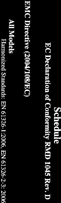
17 Quick Installation Guide Rosemount 3144P PRODUCT CERTIFICATIONS Rosemount 3144P With HART / 4 20 ma Approved Manufacturing Locations Rosemount Inc. Chanhassen, Minnesota, USA Rosemount Temperature GmbH Germany Emerson Process Management Asia Pacific Singapore European Union Directive Information The most recent revision of the European Union Declaration of Conformity can be found at ATEX Directive (94/9/EC) Rosemount Inc. complies with the ATEX Directive. Electro Magnetic Compatibility (EMC) (2004/108/EC) EN :2006 and EN :2006 Hazardous Locations Installations North American Certifications Factory Mutual (FM) Approvals E5 FM Explosion-proof, Dust Ignition-proof and Non-Incendive Certificate Number: Explosion-proof for Class I, Division 1, Groups A, B, C, D. Dust Ignition-Proof for use in Class II/III, Division 1, Groups E, F, and G. Temperature Code: T5 (T amb = 50 to 85 C) Explosion-proof and Dust Ignition-proof when installed in accordance with Rosemount drawing Indoor and outdoor use. Type 4X. NOTE For Group A, seal all conduits within 18 inches of enclosure; otherwise, conduit seal not required for compliance with NEC (A)(1). Non-incendive for use in Class I, Division 2, Groups A, B, C, and D. Suitable for use in Class II/III, Division 2, Groups F and G. Temperature Codes: T5 (T amb = 60 to 85 C) T6 (T amb = 60 to 60 C) Non-incendive when installed in accordance with Rosemount drawing
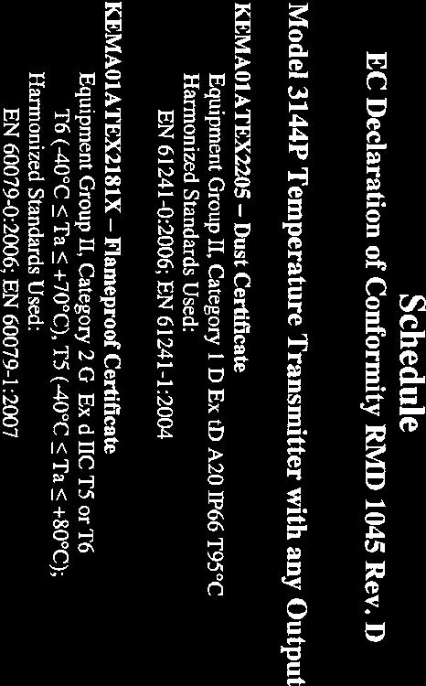
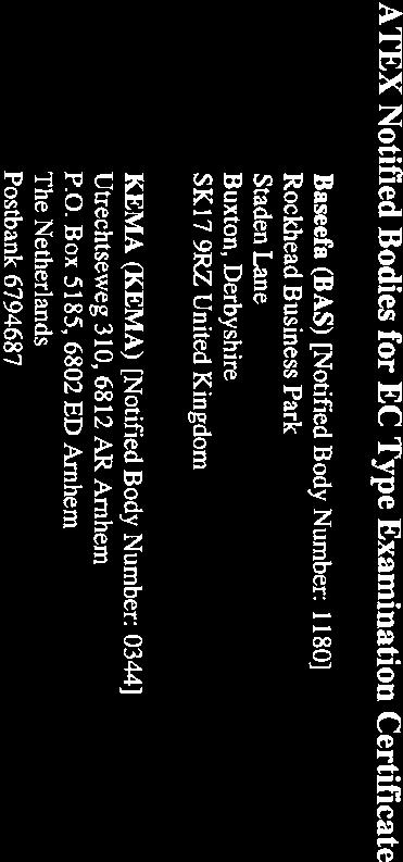
18 Rosemount 3144P Quick Installation Guide I5 FM Intrinsically Safe and Non-incendive Certificate Number: Intrinsically Safe for Class I/II/III, Division 1, Groups A, B, C, D, E, F, and G. Temperature Codes: T4A (T amb = 60 to 60 C) T5 (T amb = 60 to 50 C) Zone Marking: Class I, Zone 0, AEx ia IIC Temperature Code: T4 (T amb = 50 to 60 C) Non-incendive for use in Class I, Division 2, Groups A, B, C, and D. Suitable for use in Class II / III, Division 2, Groups F and G. Temperature Codes: T6 (T amb = 60 to 60 C) T5 (T amb = 60 to 85 C) Intrinsically Safe and Non-incendive when installed in accordance with Rosemount drawing Canadian Standards Association (CSA) Approvals I6 CSA Intrinsically Safe and Division 2 Certificate Number: Intrinsically Safe for Class I, Division 1, Groups A, B, C, and D; Class II, Division 1, Groups E, F, and G; Class III, Division 1 Suitable for Class I, Division 2, Groups A, B, C, and D. Intrinsically Safe and Division 2 when installed per Rosemount drawing K6 Combination of I6 and the following: Explosion-proof for Class I, Division 1, Groups A, B, C, and D; Class II, Division 1, Groups E, F, and G; Class III, Division 1 hazardous locations. Factory sealed. European Certifications E1 ATEX Flameproof (Zone 1) Certificate Number: KEMA01ATEX2181X ATEX Category Marking II 2 G Ex d IIC T6 (T amb = 40 to 70 C) Ex d IIC T5 (T amb = 40 to 80 C) Maximum Supply Voltage: 42.4 Vdc Special Conditions for Safe Use (X): For information on the dimensions of the flameproof joints the manufacturer shall be contacted. I1 ATEX Intrinsic Safety (Zone 0) Certificate Number: BAS01ATEX1431X ATEX Category Marking II 1 G Ex ia IIC T6 (T amb = 60 to 50 C) Ex ia IIC T5 (T amb = 60 to 75 C) 18
19 Quick Installation Guide Rosemount 3144P Table 3. Input Entity Parameters Power/Loop Sensor U i = 30 Vdc C i = 5 nf U o = 13.6 V C i = 78 nf I i = 300 ma L i = 0 I o = 56 ma L i = 0 P i = 1.0 W P o =190 mw Special Conditions for Safe Use (X): The transmitter is not capable of withstanding the 500 V insulation test as defined in Clause of EN This condition must be taken into account during installation. N1 ATEX Type n (Zone 2) Certificate Number: BAS01ATEX3432X ATEX Category Marking II 3 G Ex nl IIC T6 (T amb = 40 to 50 C) Ex nl IIC T5 (T amb = 40 to 75 C) U i = 42.4 V Special Conditions for Safe Use (X): The transmitter is not capable of withstanding the 500 V insulating test required by Clause 9.1 of EN50021:1999. This condition must be taken into account during installation. ND ATEX Dust Ignition-proof Certificate Number: KEMA01ATEX2205 ATEX Category Marking II 1 D Ex td A20 IP66 T95 C (T amb = 40 to 80 C) Maximum Supply Voltage: 42.4 Vdc International Certifications IECEx Certifications E7 IECEx Flameproof Certificate Number: IECEx KEM X Ex d IIC T6 (T amb = -40 to 70 C) Ex d IIC T5 (T amb = -40 to 80 C) Maximum Supply Voltage: 42.4 V Special Conditions for Safe Use (X): For information on the dimensions of the flameproof joints the manufacturer shall be contacted. I7 IECEx Intrinsic Safety Certificate Number: IECEx BAS X Ex ia IIC T6 (T amb = 60 to 50 C) Ex ia IIC T5 (T amb = 60 to 75 C) 19
20 Rosemount 3144P Quick Installation Guide Table 4. Input Entity Parameters Power/Loop Sensor U i = 30 V C i = 5 nf U o = 13.6 V C i = 78 nf I i = 300 ma L i = 0 I o = 56 ma L i = 0 P i = 1.0 W P o = 190 mw Special Conditions for Safe Use (X): When fitted with the transient terminal options, the apparatus is not capable of withstanding the 500 V electrical strength test as defined in Clause of IEC : This must be taken into account during installation. N7 IECEx Type n Certificate Number: IECEx BAS X Ex na nl IIC T6 (T amb = 40 to 50 C) Ex na nl IIC T5 (T amb = 40 to 75 C) U i = 42.4 V Special Conditions for Safe Use (x): When fitted with the transient terminal options, the apparatus is not capable of withstanding the 500 V electrical strength test as defined in Clause of IEC : This must be taken into account during installation. NK IECEx Dust Ignition-proof Certificate Number: IECEx KEM Ex td A20 IP66 T95 C (T amb = -40 to 80 C) Maximum Supply Voltage: 42.4 Vdc Consult factory for NF availability Brazilian Certifications Centro de Pesquisas de Energia Eletrica (CEPEL) Approval E2 INMETRO Flameproof Certificate Number: CEPEL-EX-0307/2004X BR-Ex d IIC T6 (T amb = -40 to 65 C) BR-Ex d IIC T5 (T amb = -40 to 80 C) Special Conditions for Safe Use (X): 1. The accessory of cable entries or conduit must be certified as flameproof and needs to be suitable for use conditions. 2. For ambient temperature above 60 ºC, cable wiring must have minimum isolation temperature 90 ºC, to be in accordance to equipment operation temperature. 3. Where electrical entry is via conduit, the required sealing device must be assembled immediately close to enclosure. 20
21 Quick Installation Guide Rosemount 3144P I2 INMETRO Intrinsic Safety Certificate Number: CEPEL-Ex-0723/05X BR-Ex ia IIC T6 (T amb = -60 to 50 C) BR-Ex ia IIC T5 (T amb = -60 to 75 C) Enclosure: IP66W Special Conditions for Safe Use (X): 1. The apparatus enclosure may contain light metals. The apparatus must be installed in such a manner as to minimize the risk of impact or friction with other metal surfaces. 2. A transient protection device can be fitted as an option, in which the equipment will not pass the 500 V test. Japanese Certifications E4 TIIS Flameproof Various certificates and configurations available. Consult factory for certified assemblies. China (NEPSI) Certifications I3 China Intrinsic Safety Ex ia IIC T4 Certificate Number: GYJ06586/GYJ06587 Special Conditions for Safe Use (x): 1. The temperature of the process medium must be less than +121 C. 2. The ambient temperature range is from -40 C to + 60 C. 3. Safety Parameters: Table 5. NEPSI Input Entity Parameters HART Protocol, including SIS Input Parameters RTD Terminals U i = 30 V U o = 14.1 V l i = 300 ma l o = 18.6 ma P i = 1.0 W P o = 65.7 W C i = F C o = 0.63 F L i = 0 mh L o = 93.3 mh 4. The cable entry of the temperature transmitter must be protected to ensure the degree of protection of the enclosure to IP 20(GB ) at least. 5. The terminals for connection to power supply of the temperature transmitter must be connected to an associated apparatus certified by NEPSI in accordance with GB and GB to establish an intrinsic safety system. The following requirements must be fulfilled: 21
22 Rosemount 3144P Quick Installation Guide U o U i I o I i P o P i C o C i + C c L o L c + L i Where: C c, L c the distributed capacitance and inductance of the cables U o, I o, P o maximum output parameters of the associated apparatus C o, L o maximum external parameters of the associated apparatus 6. The terminals for connection to sensor of temperature transmitter must be connected to an intrinsic safety sensor certified by NEPSI in accordance with GB and GB to establish an intrinsically safe system. The following requirements must be fulfilled: U i U o I i I o P o P i C i C o - C c L i L c - L o Where: C c, L c the distributed capacitance and inductance of the cables U i, I i, P i maximum input parameters of intrinsically safe sensor C i, L i maximum internal parameters of intrinsically safe sensor 7. The cables between temperature transmitter, associated apparatus, and sensor are 2-core shielded cables (the cables must have insulated shield). The cable core section area should be more than 0.5 mm 2. The shielded cable has to be grounded in a non-hazardous area and isolated from the housing. The wiring has to not be affected by electromagnetic disturbance. 8. Associated apparatus should be installed in a safe location. During installation, operation, and maintenance, the regulations of the instruction manual have to be strictly observed. 9. End users are not permitted to change the internal components or hardware of the device. 10. During installation, operation, and maintenance of the temperature transmitter, observe the following standards: a. GB Electrical apparatus for explosive gas atmospheres Part 13: Repair and overhaul for apparatus used in explosive gas atmospheres. b. GB Electrical apparatus for explosive gas atmospheres Part 15: Electrical installations in hazardous area (other than mines). c. GB Code for construction and acceptance of electric device for explosion atmospheres and fire hazard electrical equipment installation engineering. 22
23 Quick Installation Guide Rosemount 3144P E3 China Flameproof Ex d IIC T6 Certificate Number: GYJ06583/GYJ06584 Special Conditions for Safe Use (x): 1. Device must only be subjected to the ambient temperature range from -40 C to +70 C. 2. The temperature of the process medium must be less than +80 C. 3. The ground connection must be properly and reliably connected within the enclosure of the device. 4. During installation, use, and maintenance of the temperature transmitter, observe the warning Don t open the cover when the circuit is live. 5. During installation, there should be no mixture harm to the flameproof housing. 6. When installing in hazardous locations, the cable entry must be certified by NEPSI with protection type Ex d II C, in accordance with GB and GB Five full threads must be engaged when the cable entry is assembled to the temperature transmitters. 7. The diameter of the cable must observe the instruction manual of cable entry. The compressing nut should be fastened. The aging of seal ring should be changed in time. 8. Maintenance must be performed in a non-hazardous location. 9. The end user is not permitted to change any of the internal components or hardware of the device. 10.During installation, operation, and maintenance of the temperature transmitter, observe the following standards: a. GB Electrical apparatus for explosive gas atmospheres Part 13: Repair and overhaul for apparatus used in explosive gas atmospheres. b. GB Electrical apparatus for explosive gas atmospheres Part 15: Electrical installations in hazardous area (other than mines). c. GB Code for construction and acceptance of electric device for explosion atmospheres and fire hazard electrical equipment installation engineering. Combination Certifications Stainless steel certification tag is provided when optional approval is specified. Once a device labeled with multiple approval types is installed, it should not be reinstalled using any other approval types. Permanently mark the approval label to distinguish it from unused approval types. KA KB K1 K7 K5 K6 Combination of K1 and K6 Combination of K5 and K6 Combination of E1, N1, I1, and ND Combination of E7, N7, and I7 Combination of I5 and E5 CSA Combination 23
24 Rosemount 3144P Quick Installation Guide Additional Certifications SBS American Bureau of Shipping (ABS) Type Approval Certificate Number: 02-HS289101/1-PDA Intended Service: Measurement of temperature applications on ABS Classed Vessels, Marine and Offshore installations. ABS Rule: 2009 Steel Vessels Rules: 1-1-4/ /1.11, 4-8-3/13.1, 4-8-3/13.3; 2008 MODU Rules 4-3-3/3.1.1, /9.3.1, 4-3-3/9.3.2 SBV Bureau Veritas (BV) Type Approval Shipboard Certificate Number: 23154/AO BV Requirements: Bureau Veritas Rules for the Classification of Steel Ships Application: Approval valid for ships intended to be granted with the following additional class notations: AUT-UMS, AUT-CCS, AUT-PORT and AUT-IMS. Cannot be installed on diesel engines. SDN Det Norske Veritas (DNV) Type Approval Certificate Certificate Number: A Intended Service: The Rosemount 3144P is found to comply with Det Norske Veritas' Rules for Classification of Ships, High Speed & Light Craft and Det Norske Veritas' Offshore Standards. Table 6. Application Location Temperature Humidity Vibration EMC Enclosure Class D B A A D SLL Lloyd's Register Type Approval Certificate Certificate Number: 11/60002 Application: Marine, offshore and industrial use. Suitable for use in environmental categories ENV1, ENV2, ENV3 and ENV5 as defined in LR Test Specification No. 1: GOSTANDART Tested and approved by Russian Metrological Institute. Measuring Instruments Directive Parts Certification The Rosemount 3144P Temperature Transmitter and Rosemount 0065 RTD Temperature Sensor have been certified to meet the European Union Measurement Instrument Directive (MID) for Custody Transfer metering of liquids and gases. (1) Choosing Rosemount Temperature for a MID solution ensures that critical temperature measurement equipment will meet high expectations for unmatched system accuracy and reliability. For more information, please contact your local Emerson Process Management Representative. (1) Limited global availability. Consult factory for available ordering locations. 24


25 Quick Installation Guide Rosemount 3144P 25


26 Rosemount 3144P Quick Installation Guide 26

27 Quick Installation Guide Rosemount 3144P 27
28 Rosemount 3144P Quick Installation Guide 28
Rosemount 644H and 644R Smart Temperature Transmitters
 Quick Installation Guide March 2011 Rosemount 644 Rosemount 644H and 644R Smart Temperature Transmitters Start Step 1: Configure (Bench Calibration) Step 2: Verify Configuration Step 3: Set the Switches
Rosemount 3144P Rosemount 3144P Temperature Transmitter
 Temperature Transmitter Sensor Drift Alert and Hot Backup features improve measurement reliability while the Transmitter-Sensor Matching feature improves temperature measurement accuracy Statistical Process
Rosemount 3144P Rosemount 3144P Temperature Transmitter
 Product Data Sheet Rosemount 3144P Rosemount 3144P Temperature Transmitter Industry-leading temperature transmitter delivers unmatched field reliability and innovative process measurement solutions Achieve
Rosemount 2088, 2090P, and 2090F Pressure Transmitters
 April 2013 Rosemount 2088 and 2090 Rosemount 2088, 2090P, and 2090F Pressure Transmitters with 4-20 ma HART and 1-5 Vdc HART Low Power Protocol Start Step 1: Mount the Transmitter Step 2: Set the Jumpers
Rosemount 248 Temperature Transmitter. Quick Start Guide , Rev. EA April 2013
 Rosemount 248 Temperature Transmitter 00825-0100-4825, Rev. EA NOTICE This installation guide provides basic guidelines for the Rosemount 248 Wireless. It does not provide instructions for detailed configuration,
Annubar Flowmeter Series
 Reference Manual Appendix B Approvals Annubar Flowmeter Series Hazardous Locations Installations.................. page B-1 Rosemount 3051SFA Product Certifications.......... page B-1 Rosemount 3095MFA
Rosemount 4500 Hygienic Pressure Transmitter. Start
 Quick Installation Guide June 2007 Rosemount 4500 Rosemount 4500 Hygienic Pressure Transmitter ProductDiscontinued Start Step 1: Mount the Transmitter Step 2: Set the Switches Step 3: Connect Wiring and
Model 144H. Product Data Sheet , Rev DB February Content
 Rosemount 144 PC-Programmable Temperature Transmitter Provides an installation-ready solution for temperature monitoring applications using Complete Point Solutions (CPS) Increases measurement accuracy
Rosemount 2051 Pressure Transmitter with 4-20 ma HART and 1-5 Vdc HART Low Power Protocol
 Quick Installation Guide August 2009 Rosemount 2051 Rosemount 2051 Pressure Transmitter with 4-20 ma HART and 1-5 Vdc HART Low Power Protocol Start Step 1: Mount the Transmitter Step 2: Consider Housing
Rosemount 3051 Pressure Transmitter Includes Transmitter Option TR ProductDiscontinued. Start
 Quick Installation Guide June 2009 Rosemount 3051 Rosemount 3051 Pressure Transmitter Includes Transmitter Option TR ProductDiscontinued Start Step 1: Mount the Transmitter Step 2: Consider Housing Rotation
Rosemount 3051 Pressure Transmitter
 Quick Start Guide 00825-0100-4001, rev. JA Rosemount 3051 Pressure Transmitter with 4-20 ma HART and 1-5 Vdc Low Power Protocol Rosemount 3051CF Series Flowmeter Transmitter with 4-20 ma HART and 1-5 Vdc
Rosemount 702 Wireless Discrete Transmitter
 August 2009 Rosemount 702 Rosemount 702 Wireless Discrete Transmitter Start Step 1: Physical Installation Step 2: Verify Operation Step 3: Reference Information Product Certifications EC Declaration of
Rosemount 644 Temperature Transmitter
 Quick Start Guide 00825-0200-4728, Rev GB Rosemount 644 Temperature Transmitter with 4 20 ma HART Protocol (Revision 5 and 7) Note Before installing the transmitter, confirm the correct device driver is
Quick Start Guide , Rev DA June Rosemount 644H (Device Revision 7 or Previous) and 644R Smart Temperature Transmitters
 and 644R Smart Temperature Transmitters") Quick Start Guide 00825-0100-4728, Rev DA Rosemount 644H (Device Revision 7 or Previous) and 644R Smart Temperature Transmitters Quick Start Guide NOTICE This guide provides basic guidelines for the Rosemount
Quick Start Guide 00825-0100-4728, Rev DA Rosemount 644H (Device Revision 7 or Previous) and 644R Smart Temperature Transmitters Quick Start Guide NOTICE This guide provides basic guidelines for the Rosemount
Rosemount 3051S MultiVariable Transmitter
 HART Reference Card HART Rosemount 3051SMV Rosemount 3051S MultiVariable Transmitter A check ( ) indicates the basic configuration parameters. At minimum, these parameters should be verified as part of
Rosemount 3144P Temperature Transmitter
 Temperature Transmitter Sensor Drift Alert and Hot Backup features improve measurement reliability while the Transmitter-Sensor Matching feature improves temperature measurement accuracy Statistical Process
Model 144H. Product Data Sheet , Rev DB February Content
 Rosemount 144 PC-Programmable Temperature Transmitter Provides an installation-ready solution for temperature monitoring applications using Complete Point Solutions (CPS) Increases measurement accuracy
Quick Start Guide , Rev HA January Rosemount 248 Temperature Transmitter
 00825-0100-4825, Rev HA Rosemount 248 Temperature Transmitter NOTICE This guide provides basic guidelines for the Rosemount 248. It does not provide instructions for detailed configuration, diagnostics,
Rosemount 3144P Temperature Transmitter
 Temperature Transmitter Sensor Drift Alert and Hot Backup features improve measurement reliability while the Transmitter-Sensor Matching feature improves temperature measurement accuracy. Communicates
J. Rosemount 3051S Series Pressure Transmitter and Rosemount 3051SF Series Flowmeter with HART Protocol.
 Quick Installation Guide Rosemount 3051S Series Pressure Transmitter and Rosemount 3051SF Series Flowmeter with HART Protocol Rosemount 3051S Start Step 1: Mount the Transmitter Step 2: Consider Housing
Quick Start Guide , Rev CB May Rosemount 3144P Temperature Transmitters with FOUNDATION fieldbus Protocol
 Quick Start Guide 00825-0100-4834, Rev CB Rosemount 3144P Temperature Transmitters with FOUNDATION fieldbus Protocol Quick Start Guide NOTICE NOTICE This guide provides basic guidelines for the Rosemount
Rosemount 2090P Pulp and Paper Pressure Transmitter
 Product Data Sheet Rosemount 2090P Pulp and Paper Pressure Transmitter Rosemount 2090P 1-inch flush mount compatible with a PMC process connection, or 1 1 /2-inch threaded mounting connection Absolute
Rosemount 8800D Series Vortex Flowmeter
 Quick Installation Guide Rosemount 8800D Rosemount 8800D Series Vortex Flowmeter Start Step 1: Mount the Flowmeter Step 2: Consider Housing Rotation Step 3: Set Jumpers and Switches Step 4: Connect Wiring
Rosemount 752 Fieldbus Remote Indicator
 Product Data Sheet Rosemount 752 Rosemount 752 Fieldbus Remote Indicator ROSEMOUNT 752 DELIVERS: Two-wire segment powered device Displays up to 8 values Link Master Capability Optional PID, Characterizer,
Rosemount 2088, 2090F, and 2090P Pressure Transmitter
 Quick Start Guide 00825-0100-4108, Rev BA Rosemount 2088, 2090F, and 2090P Pressure Transmitter with 4-20 ma HART and 1-5 Vdc Low Power HART Protocol (Revision 5 and 7) Quick Start Guide NOTICE This guide
Rosemount 2051T In-Line Pressure Transmitter
 Rosemount 2051T In-Line Pressure Transmitter 2051T In-Line Wireless Pressure Transmitter Configuration Transmitter Output Code 4-20 ma HART 2051 A 2051 with Selectable HART (1) Lower Power 2051 2051 with
Rosemount 148 Temperature Transmitter. Quick Start Guide , Rev GA September 2016
 Rosemount 148 Temperature Transmitter 00825-0100-4148, Rev GA NOTICE This guide provides basic guidelines for the Rosemount 148. It does not provide instructions for detailed configuration, diagnostics,
Rosemount Pipe Clamp Sensor. Reference Manual , Rev BA February 2014
 Rosemount Pipe Clamp Sensor Reference Manual Reference Manual Title Page The Rosemount 0085 Pipe Clamp Sensor NOTICE Read this manual before working with the product. For personal and system safety, and
Rosemount 3144P Temperature Transmitter
 00825-0100-4021, Rev MA Rosemount 3144P Temperature Transmitter with HART Protocol and Rosemount X-well Technology NOTICE This guide provides basic guidelines for the Rosemount 3144P Transmitter. It does
Rosemount 3144P Temperature Transmitter
 Quick Start Guide 00825-0100-4021, Rev NA Rosemount 3144P Temperature Transmitter with HART Protocol and Rosemount X-well Technology Quick Start Guide NOTICE This guide provides basic guidelines for the
Rosemount 2051T In-line Pressure Transmitter
 February 2017 T In-line Pressure Transmitter T In-line Wireless Pressure Transmitter Configuration 4 20 ma HART with Selectable HART (1) Lower Power with Selectable HART (1) FOUNDATION Fieldbus PROFIBUS
Rosemount 3144P Temperature Transmitters with FOUNDATION Fieldbus Protocol. Quick Start Guide , Rev DA June 2016
 Rosemount 3144P Temperature Transmitters with FOUNDATION Fieldbus Protocol 00825-0100-4834, Rev DA NOTICE This guide provides basic guidelines for Rosemount 3144P. It does not provide instructions for
Rosemount 4500 Hygienic Pressure Transmitter
 Product Data Sheet Rosemount 4500 Rosemount 4500 Hygienic Pressure Transmitter Hygienic design conforms to 3-A and EHEDG standards Demonstrated best-in-class performance during SIP/CIP for process temperatures
Rosemount 2090F Hygienic Pressure Transmitter
 Hygienic Pressure Transmitter Conforms to 3-A Sanitary s Features CIP/SIP service for process temperatures up to 284 F (140 C) Absolute or gage pressure ranges from 0-1.5 to 0-300 psi Mounts with either
Rosemount 644 Temperature Transmitter
 Product Data Sheet September 2018 00813-0100-4728, Rev UD Rosemount 644 Temperature Transmitter The most versatile temperature transmitter Reduce complexity and simplify the day-to-day operations of your
Rosemount 848T High Density Temperature Measurement Family
 Product Data Sheet July 2017 00813-0100-4697, Rev PA Rosemount 848T High Density Temperature Measurement Family Innovative temperature measurement for high density applications that provide installation
SmartPower Solutions [ SmartPower Solutions. Quick Installation Guide , Rev AC January 2012
 Start Step 1: Physical Installation Step 2: Verify Operation Disposal/Recycling of Depleted Power Modules Product Certifications EC Declaration of Conformity End 00825-0100-4701[ 2012 Rosemount Inc. All
Rosemount 848T FOUNDATION Fieldbus High Density Temperature Transmitter
 Quick Start Guide 00825-0100-4697, Rev SF Rosemount 848T FOUNDATION Fieldbus High Density Temperature Transmitter Device Revision 8 - Requires New DD/CFF Revision Quick Start Guide NOTICE This guide provides
Rosemount 4600 Oil & Gas Panel Pressure Transmitter. Quick Start Guide , Rev GA September 2017
 Rosemount 4600 Oil & Gas Panel Pressure Transmitter 00825-0100-4022, Rev GA NOTICE NOTICE This guide provides basic guidelines for the Rosemount 4600 Oil & Gas Panel Pressure Transmitter. It does not provide
Rosemount 248 Temperature Transmitter
 Product Data Sheet March 2017 00813-0100-4825, Rev LA Rosemount 248 Temperature Transmitter Basic temperature transmitter offers a reliable solution for temperature monitoring points. Standard transmitter
Rosemount 248 Temperature Transmitter
 Product Data Sheet November 2013 00813-0100-4825, Rev KA Rosemount 248 Temperature Transmitter Basic temperature transmitter offers a reliable solution for temperature monitoring points transmitter design
Rosemount 3144P Temperature Transmitter
 Product Data Sheet August 2014 00813-0100-4021, Rev NA Rosemount 3144P Temperature Transmitter For every responsibility you have, you are confronted with a number of challenges. You have aggressive production
Rosemount 3051CFC Compact Flowmeter
 CFC Compact Flowmeter CFC Compact Flowmeters provide a quick, reliable installation between existing raised face flanges. Depending on your application needs, you can reduce energy loss with the Compact
Rosemount 2088 Absolute and Gage Pressure Transmitter
 Product Data Sheet Rosemount 2088 Rosemount 2088 Absolute and Gage Pressure Transmitter Performance of 0.075% with High Accuracy option Lightweight, compact design for cost effective installation Protocols
Rosemount 148 Temperature Transmitter. Reference Manual , Rev CA April 2014
 Rosemount 148 Temperature Transmitter Reference Manual Reference Manual Rosemount 148 Temperature Transmitter Rosemount 148 Hardware Revision 5 NOTICE Read this manual before working with the product.
Rosemount 2088 Absolute and Gage Pressure Transmitter
 Product Data Sheet February 2015 00813-0100-4690, Rev PB Rosemount 2088 Absolute and Gage Pressure Transmitter Performance of 0.065% with High Accuracy option Lightweight, compact design for cost-effective
Rosemount 3051CFP Integral Orifice Flowmeter
 December 2013 Rosemount 3051 Rosemount 3051CFP Integral Orifice Flowmeter See Specifications on page 47 and options for more details on each configuration. Rosemount 3051CFP Integral Orifice Flowmeters
Rosemount 644H Temperature Transmitters
 Quick Start Guide 00825-0100-4829, Rev DA Rosemount 644H Temperature Transmitters with FOUNDATION Fieldbus Quick Start Guide NOTICE This guide provides basic guidelines for the Rosemount 644. It does not
Rosemount 3095MFC Compact Orifice Mass Flowmeter
 Rosemount 3095MFC Compact Orifice Mass Flowmeter SPECIFICATIONS Performance System Reference Accuracy Percent (%) of mass flow rate TABLE 11. 3095MFC Compact Orifice Mass Flowmeter TYPE Repeatability ±0.1%
Quick Start Guide , Rev. BB February Rosemount 1495 Orifice Plate Rosemount 1496 Orifice Flange Union
 00825-0100-4792, Rev. BB Rosemount 1495 Orifice Plate Rosemount 1496 Orifice Flange Union NOTICE This installation guide provides basic guidelines for Rosemount 1495 Conditioning Orifice Plate. It does
Configuration Data Sheet
 Product Data Sheet Configuration Data Sheet HART / 4 20 ma / AND SAFETY CERTIFIED TRANSMITTER = Default Configuration Customer Information Customer P.O. No. Sensor Model No. Line Item Sensor Type Sensor
Rosemount 8800D Series Vortex Flowmeter. Quick Start Guide , Rev FE October 2018
 Rosemount 8800D Series Vortex Flowmeter 00825-0100-4004, Rev FE 1 About this guide This guide provides basic guidelines for the Rosemount 8800D Series Vortex Flowmeter. It does not provide instructions
Rosemount 2051G Pressure Transmitter
 Quick Start Guide 00825-0700-4101, Rev AB Rosemount 2051G Pressure Transmitter with 4 20 ma HART Protocol (Revision 5 and 7) Quick Start Guide NOTICE This guide provides basic guidelines for Rosemount
Rosemount 3051S MultiVariable Transmitter Rosemount 3051SF Series Flowmeter MultiVariable Transmitter
 Quick Start Guide 00825-0100-4803, Rev EF Rosemount 3051S MultiVariable Transmitter Rosemount 3051SF Series Flowmeter MultiVariable Transmitter Quick Start Guide NOTICE This guide provides basic guidelines
Rosemount 248 Temperature Transmitter
 Product Data Sheet January 2018 00813-0100-4825, Rev LB Rosemount 248 Temperature Transmitter Basic temperature transmitter offers a reliable solution for temperature monitoring points. Standard transmitter
Rosemount 4500 Hygienic Pressure Transmitter Demonstrated best-in-class performance during SIP/CIP for process temperatures up to 400 F (204 C)
") Product Data Sheet December 2012 00813-0100-4027, Rev BB Rosemount 4500 Hygienic Pressure Transmitter ProductDiscontinued R 37-01 Hygienic design conforms to 3-A and EHEDG standards Demonstrated best-in-class
Product Data Sheet December 2012 00813-0100-4027, Rev BB Rosemount 4500 Hygienic Pressure Transmitter ProductDiscontinued R 37-01 Hygienic design conforms to 3-A and EHEDG standards Demonstrated best-in-class
Rosemount 3490 Series
 Product Data Sheet July 2014 00813-0100-4841, Rev DA Rosemount 3490 Series 4 20 ma + HART Compatible Controller Field mounted controller with integral multi-function LCD and keypad Tough weatherproof wall
Rosemount 2090F Sanitary Pressure Transmitter with HART Protocol
 Sanitary Pressure Transmitter with HART Protocol A TRADITION OF EXCELLENCE IN PERFORMANCE Conforms to 3-A Sanitary Standards Features CIP/SIP service with an upper temperature limit of 284 F (140 C) USDA
Rosemount 752 FOUNDATION Fieldbus Remote Indicator
 Rosemount 752 FOUNDATION Fieldbus Remote Indicator Product Data Sheet 00813-0100-4377, Rev FA Two-wire segment powered device Displays up to eight values Link Master Capability Optional PID, Characterizer,
Rosemount 3051S Series Pressure Transmitter and Rosemount 3051SF Series Flowmeter
 Quick Start Guide 00825-0100-4801, Rev NA Rosemount 3051S Series Pressure Transmitter and Rosemount 3051SF Series Flowmeter with HART Protocol Quick Start Guide NOTICE This guide provides basic guidelines
Rosemount 1595 Conditioning Orifice Plate
 Quick Installation Guide December 2007 Rosemount 1595 Rosemount 1595 Conditioning Orifice Plate Start Step 1: Primary Element Location Step 2: Primary Element Orientation Step 3: Primary Element Installation
Rosemount 644H Temperature Transmitters
 Quick Start Guide 00825-0300-4728, Rev BA Rosemount 644H Temperature Transmitters with PROFIBUS PA Quick Start Guide NOTICE This guide provides basic guidelines for the Rosemount 644. It does not provide
Sensor Wiring Instructions and Approval Drawings
 Manual Supplement Series 58C, 68, 68Q, and 78 RTD Sensor Wiring Instructions and Approval Drawings Wiring Instructions.................................... page 1-1 Approval Drawings for Hazardous Location
Rosemount 2088 Absolute and Gage Pressure Transmitter
 Product Data Sheet Rosemount 2088 Rosemount 2088 Absolute and Gage Pressure Transmitter Absolute and gage pressure ranges from 0 1.5 psi to 0 4,000 psi (0 0.1 to 0 276 bar) Performance of 0.075% with high
Rosemount 3051S MultiVariable Transmitter Rosemount 3051SF Series MultiVariable Flowmeter
 Quick Start Guide 00825-0100-4853, Rev AD Rosemount 3051S MultiVariable Transmitter Rosemount 3051SF Series MultiVariable Flowmeter with FOUNDATION Fieldbus Protocol Quick Start Guide NOTICE This guide
Rosemount 3051S Series of Instrumentation
 Product Data Sheet October 2017 00813-0100-4801, Rev UG Rosemount 3051S Series of Instrumentation Scalable pressure, flow, and level solutions Innovation reaching across your operation With the Rosemount
Rosemount 3051L Level Transmitter
 Rosemount 3051 December 2013 Rosemount 3051L Level Transmitter The Rosemount 3051L Level transmitter combines the performance and capabilities of Rosemount 3051 transmitters with the reliability and quality
SmartPower Solutions. Quick Start Guide , Rev CA March 2015
 SmartPower Solutions 00825-0100-4701, Rev CA NOTICE This guide provides basic guidelines for the SmartPower family of products. It does not provide instructions for detailed configuration, diagnostics,
SmartPower Solutions. SmartPower Solutions. Product Data Sheet , Rev AC January Contents
 Product Data Sheet Intrinsically Safe design enables ability to perform routine maintenance in hazardous areas Predictable life specified under installed conditions Robust design for use in harsh environments
Rosemount 2160 Wireless Vibrating Fork Level Switch
 January 2012 Rosemount 2160 Rosemount 2160 Wireless Vibrating Fork Level Switch Start Considerations and Recommendations Step 1: Physical Installation Step 2: Verify Operation Step 3: Reference Information
Rosemount 2051 Pressure Transmitter
 Rosemount 2051 Pressure Transmitter Product Data Sheet April 2013 00813-0100-4101, Rev JA Coplanar platform enables integration of primary elements, manifolds, and remote seal solutions Best in Class performance
Rosemount 3051S Series of Instrumentation
 Product Data Sheet January 2016 00813-0100-4801, Rev UA Rosemount 3051S Series of Instrumentation Scalable pressure, flow, and level solutions Innovation reaching across your operation With the Rosemount
Rosemount 3051SFC Compact Orifice Flowmeter
 Rosemount Compact Orifice Product Data Sheet Rosemount 3051SFC Compact Orifice Flowmeter SPECIFICATIONS Performance System Reference Accuracy Percent (%) of volumetric flow rate TABLE 1. 3051SFC Compact
Rosemount 644H Temperature Transmitters
 Quick Start Guide 00825-0300-4728, Rev CA Rosemount 644H Temperature Transmitters with PROFIBUS PA Quick Start Guide NOTICE This guide provides basic guidelines for the Rosemount 644. It does not provide
SAFETY MANUAL. PointWatch Eclipse Infrared Hydrocarbon Gas Detector Safety Certified Model PIRECL
 SAFETY MANUAL PointWatch Eclipse Infrared Hydrocarbon Gas Detector SIL 2 Certified Model PIRECL Safety Certified Model PIRECL PointWatch Eclipse IR Gas Detector This manual addresses the specific requirements
Rosemount 3490 Series 4 20 ma + HART Compatible Controller
 00825-0200-4841, Rev AB Rosemount 3490 Series 4 20 ma + HART Compatible Controller Failure to follow safe installation guidelines could result in death or serious injury The Rosemount 3490 Series Control
Rosemount 2051 Pressure Transmitter
 Rosemount 2051 Pressure Transmitter Product Data Sheet May 2016 00813-0100-4101, Rev KB Rosemount Coplanar platform enables integration of primary elements, manifolds, and remote seal solutions Best in
User s Manual. YTA110, YTA310, YTA320, and YTA710 Temperature Transmitters. Manual Change No
 User s Manual YTA110, YTA310, YTA320, and YTA710 Temperature Transmitters Manual Change No. 16-045 Please use this manual change for the manuals listed below. 1. Applicable manuals, revised item, revised
Rosemount 214C Sensor. Quick Start Guide , Rev AF August 2017
 Rosemount 214C Sensor 00825-0400-2654, Rev AF NOTICE This guide provides basic guidelines for Rosemount 214C Sensor models. If the sensor was ordered assembled to a temperature thermowell or transmitter,
Temperature Measurement Transmitters for field mounting
 Siemens AG 07 Overview Application The SITRANS TF can be used everywhere where temperatures need to be measured under particularly harsh conditions. For that reasons users from all industries have opted
Rosemount 3490 Series 4 20 ma + HART Compatible Controller
 00825-0100-4841, Rev BA Rosemount 3490 Series 4 20 ma + HART Compatible Controller Quick Start Guide for Installation Failure to follow safe installation guidelines could result in death or serious injury
Rosemount 8600 Series Vortex Flowmeter. Quick Start Guide , Rev EB April 2018
 Rosemount 8600 Series Vortex Flowmeter 00825-0100-4860, Rev EB April 2018 April 2018 1 About this guide This guide provides basic guidelines for the Rosemount 8600D Series Vortex Flowmeter. It does not
Rosemount 3051 Pressure Transmitter
 Rosemount 3051 Pressure Transmitter Product Data Sheet September 2014 00813-0100-4001, Rev SA With the Rosemount 3051 Pressure Transmitter, you ll gain more control over your plant. You ll be able to reduce
Rosemount 0085 Pipe Clamp Sensor Assembly. Quick Start Guide , Rev CA June 2016
 Rosemount 0085 Pipe Clamp Sensor Assembly 00825-0100-4952, Rev CA NOTICE This guide provides basic guidelines for Rosemount 0085 Pipe Clamp Sensor. It does not provide instructions for configuration, diagnostics,
Rosemount 3051S Series Pressure Transmitter and Rosemount 3051SF Series Flowmeter
 Quick Start Guide 00825-0100-4801, Rev MC Rosemount 3051S Series Pressure Transmitter and Rosemount 3051SF Series Flowmeter with HART Protocol Quick Start Guide NOTICE This guide provides basic guidelines
Rosemount 2088, 2090P, and 2090F Pressure Transmitters
 Quick Start Guide 00825-0100-4690, Rev FD Rosemount 2088, 2090P, and 2090F Pressure Transmitters with 4 20 ma HART and 1 5 Vdc HART Low Power Protocol Quick Start Guide NOTICE This installation guide provides
Rosemount 3051 Pressure Transmitter
 Rosemount 3051 Pressure Transmitter Product Data Sheet December 2017 00813-0100-4001, Rev TB With the Rosemount 3051 Pressure Transmitter, you ll gain more control over your plant. You ll be able to reduce
Rosemount 3051S MultiVariable Transmitter Rosemount 3051SF Series Flowmeter MultiVariable Transmitter
 Quick Start Guide 00825-0100-4803, Rev EA Rosemount 3051S MultiVariable Transmitter Rosemount 3051SF Series Flowmeter MultiVariable Transmitter Quick Start Guide NOTICE This guide provides basic guidelines
Rosemount 3100 Series Ultrasonic Level Transmitters
 Product Data Sheet Ultrasonic Level Transmitters Non-contacting measurement with no moving parts Integral LCD and push-buttons as standard for on-site programming Continuous measurement of level or distance-to-surface.
SAFETY MANUAL. Electrochemical Gas Detector GT3000 Series Includes Transmitter (GTX) with H 2 S or O 2 Sensor Module (GTS)
 with H 2 S or O 2 Sensor Module (GTS)") SAFETY MANUAL Electrochemical Gas Detector GT3000 Series Includes Transmitter (GTX) with H 2 S or O 2 Sensor Module (GTS) Sensor Module (GTS) Transmitter (GTX) Detector (GT3000) SAFETY CERTIFIED GT3000
SAFETY MANUAL Electrochemical Gas Detector GT3000 Series Includes Transmitter (GTX) with H 2 S or O 2 Sensor Module (GTS) Sensor Module (GTS) Transmitter (GTX) Detector (GT3000) SAFETY CERTIFIED GT3000
Rosemount 3100 Series Ultrasonic Level Transmitters
 Product Data Sheet Ultrasonic Level Transmitters Non-contacting measurement with no moving parts Integral LCD and push-buttons as standard for on-site programming Continuous measurement of level or distance-to-surface.
Rosemount 8800D Series Vortex Flowmeter
 Product Data Sheet May 2013 00813-0100-4004, Rev JB Rosemount 8800D Series Vortex Flowmeter Hart and FOUNDATION fieldbus Protocols All welded, non-clog design provides maximum performance, reliability
Rosemount 8732E Magnetic Flowmeter System with Profibus PA digital fieldbus (Transmitter and Sensor)
") Quick Installation Guide January 2010 Rosemount 8732 Rosemount 8732E Magnetic Flowmeter System with Profibus PA digital fieldbus (Transmitter and Sensor) Start Step 1: Pre-Installation Step 2: Handling
Quick Installation Guide January 2010 Rosemount 8732 Rosemount 8732E Magnetic Flowmeter System with Profibus PA digital fieldbus (Transmitter and Sensor) Start Step 1: Pre-Installation Step 2: Handling
Rosemount 4600 Oil & Gas Panel Pressure Transmitter
 Product Data Sheet October 2017 00813-0100-4022, Rev LA Rosemount 4600 Oil & Gas Panel Pressure Transmitter A compact, lightweight, all-welded stainless steel design Up to 40:1 rangeability for increased
SAFETY CERTIFIED MODEL FP-700 COMBUSTIBLE GAS DETECTOR
 SAFETY MANUAL SIL 2 Certified Model FP-700 Combustible Hydrocarbon Gas Sensor Version 2.0 1 SAFETY CERTIFIED MODEL FP-700 COMBUSTIBLE GAS DETECTOR This manual addresses the specific requirements and recommendations
Fisher LCP100 Local Control Panel
 Instruction Manual LCP100 Local Control Panel Fisher LCP100 Local Control Panel Contents Introduction... 1 Scope of Manual... 1 Description... 2 Specifications... 2 Installation... 3 Hazardous Area Classifications
Rosemount 3051S MultiVariable Extension Supplement
 Product Data Sheet April 2015 00813-0400-4801, Rev AA Rosemount 3051S MultiVariable Extension Supplement With the Rosemount 3051S MultiVariable Extensions, you can gain valuable process insight with two
Rosemount 3051SFP Proplate Flowmeter
 SPECIFICATIONS Rosemount 3051SFP Proplate Flowmeter Performance System Reference Accuracy Percentage (%) of volumetric flow rate (1) Beta ( ) (2) Repeatability ±0.1% Line Sizes 1 /2-in. (15 mm) 1-in. (25
Rosemount 2088, 2090F, and 2090P Pressure Transmitter
 Quick Start Guide 00825-0100-4108, Rev CA Rosemount 2088, 2090F, and 2090P Pressure Transmitter with 4 20 ma HART and 1 5 Vdc Low Power HART Protocol (Revision 5 and 7) Quick Start Guide NOTICE This guide
STT 3000 Series STT250 Smart Temperature Transmitters Specifications Models STT25T EN0l-6091 February 2009
 STT 3000 Series STT250 Smart Temperature Transmitters Specifications Models STT25T EN0l-6091 February 2009 Introduction Honeywell s STT 3000 family of microprocessor based transmitters covers the full