Important Notice This guide is delivered subject to the following conditions and restrictions:
|
|
|
- Conrad Nathaniel Wells
- 5 years ago
- Views:
Transcription


1 Installer Manual


2 Important Notice This guide is delivered subject to the following conditions and restrictions: This guide contains proprietary information belonging to RISCO Group. Such information is supplied solely for the purpose of assisting explicitly and properly authorized users of the system. No part of its contents may be used for any other purpose, disclosed to any person or firm, or reproduced by any means, electronic or mechanical, without the express prior written permission of RISCO Group. The information contained herein is for the purpose of illustration and reference only. Information in this document is subject to change without notice. Corporate and individual names and data used in examples herein belong to their respective owners. Compliance Statement Hereby, RISCO Group declares that the Agility series of central units and accessories are designed to comply with: EN , EN Grade 2 EN Environmental class II EN Type A UK: DD243:2004, PD 6662:2004, ACPO (Police) USA: FCC: Part 15B, FCC part 68 CANADA: CS 03, DC 01 All rights reserved RISCO Group March 2010 Page ii
3 Table of Contents CHAPTER 1 INTRODUCTION ARCHITECTURE MAIN FEATURES TECHNICAL SPECIFICATIONS CHAPTER 2 INSTALLING THE AGILITY AGILITY MAIN COMPONENTS MOUNTING THE AGILITY Choosing the mounting location Wall Mounting the Agility Connecting the Backup Battery Connecting the Agility to Power Supply Configuration A Ground Connection Connecting the Agility to Power Supply Configuration B Completing Installation DIP switch setting Connecting a telephone line to the Agility Connecting a network cable to the Agility SIM Card Installation External Audio Unit CHAPTER 3 INSTALLER PROGRAMMING PROGRAMMING METHODS Configuration Software Wireless Keypad Installer Keypad PTM: Data Storing Device WIRELESS DEVICE ALLOCATION Quick Allocation using the main unit button Allocation using the keypad Allocation using the Configuration Software Transmitters Write Message Method DELETING WIRELESS ACCESSORIES CHAPTER 4 INSTALLER MENUS USING THE AGILITY KEYPAD KEYS ACCESSING THE INSTALLER MENUS PROGRAMMING MENU Page iii
4 1. Programming: System Menu Timers Controls Labels Sounds System Settings Service Information Firmware Update Programming: Radio Devices Menu Allocation Modification Identification Programming: Codes Menu User Grand Master Installer Sub Installer Code Length DTMF Code Parent Control Programming: Communication Menu Method Monitoring Station Configuration Software Follow Me Programming: Audio Messages Menu Assign Message Local Message TESTING MENU Main Unit Zone Remote Control Keypad Siren GSM IP Unit UO Unit ACTIVITIES MENU FOLLOW ME MENU CLOCK MENU Page iv
5 EVENT LOG MENU MACRO MENU Programming Macro Keys Activating a Macro APPENDIX A REPORT CODES...A 1 APPENDIX B INSTALLER EVENT LOG MESSAGES... B 1 APPENDIX C LIBRARY VOICE MESSAGES...C 1 APPENDIX D EN COMPLIANCE... D 1 APPENDIX E INSTALLER PROGRAMMING MAPS... E 1 APPENDIX F SIA CP 01 COMPLIANCE... F 1 Page v
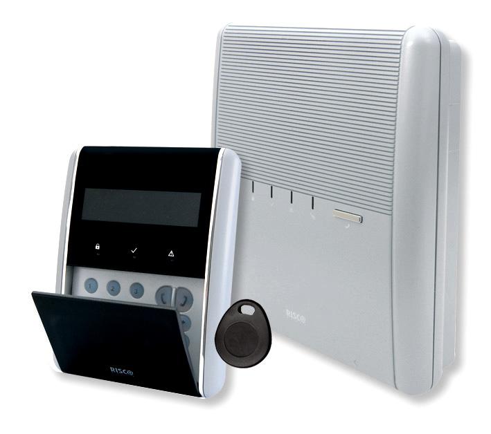
6 Chapter 1 Introduction The Agility is a Flexible Wireless Security Solution that incorporates state of the art wireless and communication technology. Agility is ideal for installation in any home or office environment and supports RISCO Group s extensive range of one way and two way wireless security and safety devices, keypads, remote controls, keyfobs, panic buttons, fully wireless sirens and other accessories. Main Benefits: Main Features: Flexible Plug in Communication IP Module GSM/GPRS Module Fast PSTN Module Use any single module, any combination or all three modules for backup, or no communication for audible only installations 2 Way Wireless Keypad with full programming capability 2 Way 8 button Wireless Remote Control with code protection, key lock and system status request and indication 2 way voice communication Easy enrolling of Wireless Devices without a keypad Remote enrolling according to Device ID Combine one way or two way transmitters in the same system Flash memory for easy firmware upgrade Simple physical installation with wall brackets Separate main panel, can be hidden for higher security Program Transfer Module (PTM) for program backup Simplified menu logic (only menus of installed devices are displayed, only menus according to the authorization code are displayed) 32 wireless zones 3 partitions Up to 3 bi directional wireless keypads Up to 8 Remote Control keyfobs (combination of 8 or 4 button) or one way Input/Output module: 2 way wireless communication to the Agility Local transformer with rechargeable backup batteries 4 wired zones with selectable EOL resistance & 4 outputs (2x3A relay and 2x500mA) Includes X 10 adaptor 32 user codes 250 event log Uses regular Sealed Lead Acid Battery 6V 3.2Ah Page 1-1


7 Architecture The following diagram provides an overview of the Agilityʹs architecture and capabilities. Examine the figure before beginning with your Agility installation to obtain an overall picture of the full extent of the Agility system capabilities. Page 1-2

8 Main Features The following illustration describes the main features of the Agility: Detectors 32 Wireless zones: 4 Wired zones via optional Wireless I/O Expander Total zones: 36 More than 25 zone types Full zone supervision 2 way and 1 way detectors combined on the same system Sirens Built in siren Fully wireless external and internal wireless sirens Add up to 3 Sirens Bi directional Keypad Fully Wireless LCD display S.O.S / Two way communication emergency key Double tamper protection (Box & Wall) Codes: 1 installer code 1 sub installer code 1 grand master code 32 user codes 4 authority level Optional 4 or 6 digits code definition Follow Me: 16 follow me destinations Follow me can be defined as voice message, SMS or User control over the system Security code protection Monitoring Station Remote programming, diagnostics and communication test. Report to 3 MS. Report thought PSTN, GSM, GPRS or IP. MS polling through IP network. Account number for each MS. Flexible split reporting for backup. Call Save mode for nonurgent reports. Remote device enrollment. Voice capabilities: 2 Way communication Remote phone operation Full voice menu guide System event messaging Local announcement messages Voice description for zones, partitions, etc. Communication: Flexible communication over GSM/GPRS, IP or PSTN. Backup capability between the communication methods. Supports major reporting formats. Add on module for each communication type. Wireless Features: Signal jamming indication Receiver calibration 868MHz/433 MHz radio frequencies Programmable supervision time Tamper detection in transmitters Low battery detection in transmitters Installer Programming: Local /Remote using configuration software Program transfer module. Full programming using bi directional wireless keypad. Flexible device enrollment by serial ID serial number or by RF allocation. Keypad programming menu adjusted to existing hardware. User Operating Tools: Bi directional 8 button key fob Bi directional Keypad 4 button keyfob Remote phone operation SMS Configuration software Web browser (will be available in future versions of Agility) Home Automation 4 outputs via wireless I/O expander 16 X 10 outputs via wireless I/O expander Outputs can follow system, partition, zone or user events Outputs can be scheduled, or activated automatically, or by user command (SMS, web browser or remote phone) False Alarm Reduction: Swinger shutdown Zone crossing Report delay to MS Abort alarm feature Soak test Final exit zone Page 1-3
9 Technical Specifications The following technical specifications are applicable for the Agility: Electrical Characteristics Power Units consumptions Backup battery Internal Siren intensity Operating temperature Storage temperature Physical Characteristics Dimension Weight (no battery) Wireless Characteristics 230VAC ( 15%+10%), 50Hz, 50mA Main board: Typical 130mA GSM: Stand by 35mA, Communication 300mA Modem: Stand by 20mA, Communication 60mA IP Card: 90mA (Max) Sealed Lead Acid Battery 6V 3.2Ah C to 40 C (14 F to 131 F) 20 C to 60 C ( 4 F to 140 F) mm x mm x 64 cm (10.57 x 8.64 x 2.52 inch) 1.31Kg (Full configuration) GSM module: Kg Radio Immunity According to EN Frequency MHz/ MHz Page 1-4
10 ON Agility Installer Manual Chapter 2 Installing the Agility This chapter covers the installation procedures of the Agility, as follows: Agility Main Components, page 2 1 Mounting the Agility, page 2 2 Choosing the mounting location, page 2 2 Wall Mounting the Agility page 2 2 Connecting the Backup Battery, page 2 5 Connecting the Agility to Power Supply, page 2 6 Ground Connection, page 2 6 DIP switch setting, page 2 8 Connecting a telephone line to the Agility, page 2 9 SIM Card Installation, page 2 9 External Audio Unit, page 2 12 Agility Main Components The illustration below shows the internal components (when the Mounting Bracket is disassembled from the Back Panel) OPEN LOCK Configuration A Configuration B 15 Figure 1: Agility Main Components 1. Installation Bracket 7. Transformer 13 RS 232 communication connector 2. Telephone Jacks 8. Back Panel 14. Battery compartment 3. Audio Unit terminals 9. SIM Card socket 15. Battery compartment cover 4. Ribbon flat cable jack 10. Ribbon flat cable 16. Battery fling leads 5. AC connection terminals/dc Socket 11. DIP Switches 17. Tamper switch 6. Fuse 12 PTM connector 18. IP Card network connector Page 2-1
11 Mounting the Agility IMPORTANT: The Agility has no user replaceable parts (for instance: power cord, fuse, battery, etc.) only certified installers are allowed to replace faulty parts. Choosing the mounting location Before you mount the Agility, study the premises carefully in order to choose the exact location of the unit for the best possible coverage and yet easily accessible to prospective users of the alarm system. The mounting location of the Agility should be: Try to centrally locate the system between all the transmitters. Near an uninterrupted AC outlet. Near a telephone outlet. Far from sources of interference, such as: Direct heat sources Electrical noise such as computers, televisions etc. Large metal objects, which may shield the antenna. In a place where the alarm can be heard during Part Arming mode. Wall Mounting the Agility The Agility is comprised of two sub assemblies: Mounting bracket, Main unit which in its turn is comprised from: Front panel (not disassembled on a regular installation procedure) Back panel The mounting bracket is mounted on the wall, using the supplied proper hardware, as described below: To mount the Agility on the Wall: 1. Separate the Mounting bracket as follows: a. Release the Mounting bracket captive locking screws (1, Figure 2) located at the bottom of the unit by turning screws counterclockwise. 1 Figure 2: Mounting Bracket screws Page 2-2
12 b. Gently, pull up the Mounting bracket to a 45 angle and slide it down to release the Mounting bracket (2, Figure 3) from the two locking tabs (1, Figure 3) at the top of the unit. Note: Do not open the Mounting bracket to a larger angle in order not to break the two top tabs and not to tear up the ribbon flat cable connecting the power supply unit to the front panel (PCB). c. Disconnect the ribbon flat cable (3) from the power supply unit while leaving it connected to the Main panel. Figure 3: Mounting Bracket removal 2. Hold the Mounting bracket against the wall as a template and mark the locations for the mounting holes (5 mounting holes item 1, and an additional hole for securing the tamper protection bracket item 2, are available, see Figure 4). 3. Drill the desired mounting holes and place the screw anchors. Use the supplied 5 Philips pan head screws to attach the Mounting bracket to the wall (ST4.2 mm x 32 mm DIN 7981). 4. According to the location of the wall cables, route and insert the wires and cables via the cable s openings (3) (including AC cable and telephone cable), see figure If required, remove cable knockouts (5) to allow wire passage. 6. Anchor cables with dedicated hooks (4). Page 2-3
13 Configuration A 1 Configuration B Figure 4: Wall Installation 7. Adjust the Tamper switch (using a flat screwdriver) according to your preferred configuration. a. Box and Wall configuration (see Figure 4, detail 6) Triggers the tamper when the box or the wall mounting are tampered. b. Box only configuration (see Figure 4, detail 7) Triggers the tamper when the box is tampered. Page 2-4
14 Connecting the Backup Battery The Agility has safety approved, sealed lead acid 6V, 3.2Ah rechargeable backup battery used in time of main power failure: Note: The battery is supplied with the Agility. To insert the Backup battery: Remove the battery compartment cover screw (see Figure 5,3) located at the top of the cover by turning screw counterclockwise and pull the Agility battery cover outward Figure 5: Battery Compartment a. Insert the battery into its place and connect the flying leads to the battery according to the correct polarity (Red +) (Black ). b. Return the battery compartment cover (after placing the battery in) and secure with locking screw. Note: The Agility Rechargeable battery should be charged for at least 24 hours. 2 Important: When replacing the battery be sure to buy the same type. Failure to comply with this instruction may result in damage to personnel and/or equipment. Dispose of used batteries according to the proper instructions. Page 2-5
15 Connecting the Agility to Power Supply - Configuration A Note: The Agility panel is permanently connected to the mains. The connection must be made according to your countryʹs local regulations. As a general guideline, connect the Live Neutral and Ground using a safety approved 3 wire 18AWG power cable (14 mm minimum diameter flexible PVC cable which complies with IEC60227). The cable should be brought to the Agility panel in a protective plastic conduit (diameter 16mm minimum). A 2 pole 16A circuit breaker and earth leakage protector should be used to disconnect the live conductor, and should be provided as part of the building installation. The Agility is powered by a safety approved 230VAC. 1. Remove the power supply unit cover (Figure 6, 1). 2. Connect the power wire (Safety approved, SVT, 18AWG, 0.75mm 2 ) to the power terminal located on the power supply unit (TB1) (2, Figure 6). Note: The power wire is not supplied with the Agility. 3. DO NOT connect the cable to the wall power supply at this point. Ground Connection Grounding provides a degree of protection against lightning and induced transients for any piece of electronic equipment that may, due to lightning or static discharge, experience permanent or general malfunctions. The ideal ground is considered to be a unified earth ground in which an 8 foot copper clad rod, located close to the existing power and telephone ground rods, is sunk several feet into the earth. Appropriate hardware and clamps are then used to electrically connect each of these rods together and then to the ground terminal of the device to be protected. It may be possible to use an existing electrical ground on the premises if one is close enough to the Agility. When connecting the ground wire, use a solid 14 gauge wire [or larger (numerically lower) size]. Keep this wire as short as possible and do not run it in conduit, coil it, bend it sharply, or run it alongside other wiring. If you must bend it or change its direction, it should have a radius of at least 8 inches at the point from which it is bent. If in doubt, you may want to enlist the help of a licensed electrician in matters concerning such grounding. To connect to ground (Earth): Connect between the Agility s ground terminal and an acceptable electrical ground connection for the lightning transient protective devices in this product to be effective. Important: Connecting to ground must be performed according to the local National Electrical Code. Page 2-6
16 2 TB1 ~ 1 Figure 6: Connecting AC Power wires Connecting the Agility to Power Supply - Configuration B 1. The Agility is powered by a 9VDC/1.0A Transformer. 2. Connect the transformer power jack to the power supply located on the power supply card (1, Figure 6A). 3. DO NOT connect the transformer inlet cable to the wall power supply at this point. From 9VDC/1.0A Transformer 1 2 Figure 6A: Connecting DC Power Cable Page 2-7
17 Completing Installation 1. Set the DIP Switches according to the DIP Switch Setting section (see page 2 8). 2. Connect the ribbon flat cable between the main panel and the mounting bracket (J1). 3. Mount the Main unit to the mounting bracket using captive locking screws. 4. Plug in the power cable to the wall power outlet. 5. Power up the Agility. DIP switch setting ON Factory Default DIP Switch 1 (E A): External Audio: Used to define if the voice of the Agility will go from the main unit or from an External Audio Unit. When the external unit is connected to the Agility the voice will be heard only through the Audio voice unit. ON: External Audio Unit is connected to the Agility OFF (Default): External Audio unit not connected to the Agility. DIP Switch 2 (DFLT): Default jumper: Used when performing the following 3 operations: 1. To return installer, sub installer and grand master codes to their default factory values. Set this DIP switch to ON, disconnect all power and then reconnect the power. Note: Code Length does not change. 2. To manually erase wireless devices. Set this DIP switch to ON while power is connected. Execute a long press on the main unit button until a beep, indicating that all wireless devices have been erased, is heard. 3. To save or transfer data to or from the PTM device. ON: To transfer data from the PTM to the panel. OFF: To transfer data from the panel to the PTM. (Refer to Chapter 3 for these procedures.) DIP Switch 3 (PRGM): Enables loading local software updates to the Agility ON: software updates to the Agility can be loaded OFF (Default): software updates to the Agility can not be loaded DIP Switch 4 (BAT): Defines the Battery Discharge Protection option settings ON: Battery Discharge Protection is OFF: The battery may be totally discharged during continuous AC failure, thus battery replacement may be required (no deep discharge protection). Note: In this position the Agility will start to operate from a battery power supply whether it is connected to the Mains or not. OFF (Default): Battery deep Discharge Protection is ON: If an AC power outage occurs, the Agility automatically disconnects the battery when its backup battery voltage drops below 5.8 VDC, in order to prevent ʺdeep discharge that may damage the battery. Note: In this position the Agility will not start to operate from a battery power supply, unless connected to the Mains first. Page 2-8
18 Connecting a telephone line to the Agility Connect the system to a telephone line if the system configuration includes an internal modem (identical for Configuration A and B). 1. Connect the incoming telephone line to the plug in CONN2 jack RJ11 (pins 2, 3) or to plug in CONN3 RJ31 (pins 4, 5) (see Figure 7: Telephone Line Jacks). 2. Connect any telephone on the premises to the plug in CONN2 jack RJ11 (pins 1, 4) or to plug in CONN3 RJ31 (pins 1, 8) (see Figure 7: Telephone Line Jacks). NOTE: To ensure line seizure capability, and comply with FCC part 68 regulations, the equipment must be connected directly to the Phone company lines (ʹCOʹ). Whether connected via RJ11, RJ31, the line port must be connected to the CO lines without any other phones or other telecom equipment between them. Other telecom equipment can be connected only after (in series) the alarm panel. CONN2 RJ11 CONN3 RJ31 Figure 7: Telephone Line Jacks Page 2-9
19 Connecting a network cable to the Agility If your Agility is equipped with an IP Card, you should connect the incoming network cable in order to enable IP Communication. 1. Separate the Agility from the mounting bracket. 2. According to the location of the network cable, route and insert the cable via the cable s openings (see figure 3). 3. If required, remove cable knockouts (5, Figure 3) to allow cable passage. 4. Connect the incoming network cable to the plug in. Page 2-10
. SIM Card LOCK OPEN LOCK OPEN LOCK OPEN 1. Slide down SIM card hatch.")
20 SIM Card Installation If your Agility is equipped with a GSM/GPRS module, you should insert a SIM card in order to enable communication through the GSM/GPRS network. 1. Insert the SIM into the dedicated SIM card slot located on the rear side of the back panel (See Figure 1: Agility Main Components). SIM Card LOCK OPEN LOCK OPEN LOCK OPEN 1. Slide down SIM card hatch. 2. Open the SIM card hatch. Insert SIM card into dedicated slot. Figure 8: SIM Card Insertion 3. Close the SIM card hatch. Slide up to lock. Important: Do not install SIM card while power is applied to the Agility. Do not touch SIM Card connectors! If doing so, you may release an electrical discharge that could damage the SIM card. 2. If a PIN code is required for the SIM card, the Agility will indicate a PIN code trouble. To fix the trouble, and thus enable the SIM card to operate properly, enter the PIN code number, located in the Communication > GSM parameters menu. Note: Ensure that you have the PIN code. Be aware that after three wrong attempts (recognized by the SIM card) to enter a PIN number, the SIM card will lock. You will have to contact your local cellular provider to unlock the SIM card. 3. If you want to disable the SIM PIN code you should follow the steps: a. Insert the SIM card into a standard GSM mobile phone. b. Insert the PIN code. c. Access the phone security menu and selecting PIN OFF. Once done, re test by switching the phone OFF, then switching ON. The PIN code should not be requested again. 4. Once the SIM card is placed it is recommended to test the operation of the SIM by conducting a call and testing the GSM signal strength. For more information refer to the programming menus of the GSM menu. Note: In some countries an SMS center phone number might be required in order to enable SMS messaging. This phone number is provided by the provider. Programming the SMS center phone into the SIM can be done using a standard GSM mobile phone or from the Agility keypad or configuration software. Page 2-11
21 External Audio Unit The Agility enables to connect an external Audio Unit instead of the internal unit in order to listen to the systemʹs audio messages in a distance from the main unit. In addition the unit enables you to talk into your premises. To connect the Audio unit: 1. Wire the Audio unit to the Agility as displayed in the Wiring Diagram described in Figure 9. The terminals for wiring the Audio Unit to the Agility are located on mounting bracket the Agility. 2. Set DIP Switch 1 (E A) (External Audio) to On position. Figure 9: Wiring the External Audio Unit to Agility Page 2-12
22 Programming Methods Chapter 3 Installer Programming There are 4 available options for programming the Agility: Configuration Software Wireless Keypad Installer Keypad PTM Configuration Software A software application that enables you to program the Agility from a PC computer. It offers the following alternatives: Working locally, through a portable computer connected to the Agility via cable Working at a remote site, communicating with the Agility via a phone line, modem or IP address. For further information on programming the Agility via the Configuration software, refer to the Agility Configuration Software manual. Wireless Keypad The Agility can be fully configured via the wireless keypad. Notes: 1. The Agility can be programmed via any of the 2 way keypads in your system, but only using one keypad at a time for programming. 2. During installer programming, the keypad will turn off after 4 minutes if no entry has been made to the keys. Press any button to restore the keypad. It will display the last parameter you were working on. To program the Agility via the Wireless Keypad, follow this procedure: 1. Perform system device allocation for the keypad (refer to page 3 4). 2. Press and enter the installer code (default code is 0132). The keypad will sound a confirmation sound. Note: If a Grand Master code is required to confirm the installer code, it should be entered at this stage after the installer code. Page 3-1
23 3. Go to the Programming menu and press. Once the panel is in programming mode, the Agility main unit LEDs will flash simultaneously and a confirmation sound will be heard. Note: The installer can also program user activities by selecting the Activities menu instead of the Programming menu. Use the buttons to navigate between the menus. Installer Keypad For those systems that do not have keypads, RISCO Group offers the Agility installer a temporary keypad to be used as any Agility wireless keypad for configuring a system. An hour after exiting the programming mode the Installer Keypad will be erased from the Agility memory or when power is lost to the system. To program the Agility via the Installer Keypad, follow this procedure: 1. To allocate the Installer Keypad into the system perform a short press on the main unit button. 2. Press the buttons on the keypad simultaneously until the following message appears: 3. Enter the Grand Master code and press. The following confirmation message is heard: Installer Keypad Allocated. Note: When a wrong Grand Master code is entered, the keypad will be deleted. To continue this procedure, perform reallocation of the keypad. 4. Follow steps 2 and 3 of the wireless keypad (see page 3 1) to begin programming the system. PTM: Data Storing Device The PTM is a tiny circuit board into which the Agility panel can transmit a copy of the systemʹs configuration. The PTM stores this copy and can also transmit the configuration information back to the Agility panel. To transfer the system configuration from the panel to the PTM, follow this procedure: 1. Disconnect the flat cable and remove the Agility main unit from its wall bracket. Note: Make sure the battery is inserted into the main unit. 2. Make sure that Dipswitch 2 is set to OFF (default setting). Page 3-2
24 3. Place the PTM onto the 5 pin PTM located on the rear of the main unit PCB. The PTM LED will turn on. 4. Press the main unit button for 5 seconds. The PTM LED will flash quickly during the transmission of information to the PTM. 5. Once transmission is complete, the panel will sound a confirmation beep and the PTM LED will stop flashing and turn on steady. 6. Disconnect the PTM from the main unit. 7. Reconnect the flat cable to the main unit and replace the main unit in its wall bracket. To transfer the system configuration from the PTM to the Agility panel, follow this procedure: 1. Disconnect the flat cable and remove the Agility main unit from its wall bracket. Note: Make sure the battery is inserted into the main unit. Make sure that the Default Enable system flag is on 2. Set Dipswitch 2 to ON. 3. Place the PTM onto the 5 pin PTM connector located on the main unit PCB. 4. All LEDS on the main unit will begin to flash simultaneously. The PTM LED will flash quickly during the transmission of information to the panel. 5. Once transmission is complete, the panel will sound a confirmation beep. Note: If the procedure fails the panel will make 3 short error beeps, and you will need to do the procedure again 6. Disconnect the PTM from the main unit. 7. Reset Dipswitch 2 to OFF. 8. Reconnect the flat cable to the main unit and replace the main unit in its wall bracket. Page 3-3
25 Wireless Device Allocation Each wireless device must identify itself to the system receiver. The following section describes the different ways to allocate all of your devices to the system in order to later configure each deviceʹs parameters The learning procedure between the wireless devices and the main unit can be performed either from the main unit, a wirless keypad or via the Configuration Software. Quick Allocation using the main unit button To perform quick allocation using the main unit button, follow this procedure: Note: To enable Quick Allocation mode the System bit ʺQuick Learnʺ should be enabled. 1. Set the main unit to Learn mode with a long press on the main unit button. Each LED will light up one after another. Note: The unit will sound each time you enter or exit the Learn mode. 2. Send a transmission from each device (refer to the Transmitters write message method table in section). The system will automatically identify each device according to different categories (for example: detectors, sirens, keypads, remote controls etc.) and enter each device and its default value into the unitʹs memory. Each device receives an index number from the system. 3. Exit the Learn mode with a short press on the main unit button. Allocation using the keypad It is possible to perform allocation via the keypad in two different ways: RF Allocation or by entering the device s serial code. To perform RF Allocation via the keypad, follow this procedure: 1. Go to the Installer menu and select Programming Radio Device Allocation 1) RF Allocation. The system immediately goes into Learn mode. 2. Send a transmission from the device. (See table: Transmitters write message method) 3. The main unit will acknowledge the transmission with a sound. When the system recognizes the device the keypad LCD will display the deviceʹs serial number and category. The system also automatically allocates the device the next available index number. To perform allocation via the keypad using a serial code, follow this procedure: 1. Go to the Installer menu and select Programming Radio Device Allocation 2) By Code. Enter the device s 11 digit serial code number. Page 3-4

26 2. The system automatically recognizes the device and allocates it the next available index number. The system will sound the device type that has been allocated and the place it has been allocated to. To allocate zones to a predefined place via the keypad follow this procedure: Compared to the RF and Code allocations mentioned before, where the wireless elements are allocated automatically by the system to the first available place, when it comes to zones allocation the Agility also enables the allocation of zones to a pre defined location. 1. Go to the Installer menu and select Programming Radio Device Allocation 3) Zone Allocation. 2. Select the zone number to which you want to assign the detector and press. 3. Using the arrow keys select the allocation method: RF or Code allocation. RF allocation: Send a transmission from the device. (See table: Transmitters write message method) Code allocation: Enter the device s 11 digit serial code number. 4. The system allocates the detector into the selected index number. The system will sound the device type that has been allocated and the place it has been allocated to. Allocation using the Configuration Software It is possible to perform wireless device allocation via the configuration software in two different ways: RF Allocation or by entering the device s serial code. To perform RF allocation from the configuration software 1. Establish Communication between the main unit and the Configuration software. (For more information refer to the Configuration Software Manual) 2. Open the Activities > Radio Device Allocation screen. 3. Click on the button. This operation will set the main unit to Learn mode. The following message appears: 4. Send a transmission from the device. (See table below) Page 3-5
27 5. The main unit will acknowledge the transmission with a sound. When the system recognizes the device the Radio Device Allocation screen indicates that the status of allocation has been successful. The serial number, accessory type and the index number information will be displayed. The index number is automatically addressed by the system. Note: If required you can change the index number of the wireless device by selecting the required index number and pressing the button again. 6. To allocate an other wireless device click on the button and then repeat stages 3 7. To perform Code allocation from the configuration software 1. Establish Communication between the main unit and the Configuration software by selecting Communication>Connect from the main menu. (For more information refer to the Configuration Software Manual) 2. Open the Radio Device Allocation screen. In the Allocation area, enter the deviceʹs serial number. Note: The serial number can be found on the device. 3. Select the wireless device index number. Automatic means that the index number is automatically addressed by the system, 4. Press the button. 5. The main unit will acknowledge the transmission with a sound. When the system recognizes the device the Radio Device Allocation screen indicates that the status of allocation has been successful. Page 3-6
28 Transmitters Write Message Method How to send a write message (transmission): Wireless Device Detector/Contacts 2 Way Keypad Sending Write Message Press the tamper switch for 3 seconds 1 Way Keypad Press the key twice 1 Way Key fob 2 Way Remote Control Smoke Detector Siren Gas, CO detectors Press both keys and simultaneously for at least 2 seconds Press the button for at least 2 seconds Press both keys and simultaneously for at least 2 seconds Insert battery. Write message is send automatically within 10 seconds. Press the reset switch on the siren. After a squawk is sounded at the siren you have 10 seconds to press on the tamper switch for at least 3 seconds. Press the test button for 3 seconds 2 Panic Button Key fob Press both buttons for at least 7 seconds Deleting Wireless Accessories Deleting all wireless devices can be done manually (from the main unit) or from the Configuration software. To manually delete all wireless accessories from the system: 1. Place Dip Switch 2 to ON position. 2. Press the main unit button until it sounds. 3. Replace Dip Switch 2 to OFF position. To delete a wireless accessory from the Wireless Keypad 1. Go to the Installer menus and select Programming Radio Device Modification 2. Select the device category 3. Go to Parameters option. 4. Select the device index number 5. Go to Serial number option and type in Press. The device will be deleted Page 3-7
29 To delete a wireless accessory from the system via the Configuration software: 1. Establish Communication between the main unit and the Configuration software (For more information refer to the Configuration Software Manual) 2. In the Radio Device Allocation screen in the Delete Accessories area enter the deviceʹs serial code and click the Delete button. To delete all wireless accessories from the system via the Configuration software: 1. Establish Communication between the main unit and the Configuration software by selecting Communication>Connect from the main menu. (For more information refer to the Configuration Software Manual) 2. In the Radio Device Allocation screen in the Delete Accessories area, click the Delete All button. When all accessories have been deleted the screen will indicate that deletion has been successful. Page 3-8
30 Chapter 4 Installer Menus The following chapter describes the parameters and programming options of the system and radio devices. These parameters can be programmed via the Agility keypad or the configuration software by the installer. Note: A note appears next to the parameters that can only be programmed via the configuration software. For more information regarding the installation and use of the configuration software refer to the Configuration Software manual. Using the Agility keypad keys The Agility two way keypad contains three LED indicators, an LCD display and a variety of keys. The following table describes the typical uses of the keys when in programming mode. Keys Description The numerical keys on the keypad are used as quick keys, a numerical sequence used as a shortcut to program an option. To program the system using Quick keys: 1. Access the installer menus (see below) and select the relevant main menu option. 2. Press the quick keys in sequence to locate the parameter and press. Numerical keys are also used to input the numeric codes that may be required for arming, disarming, or used to activate specific functions. Exits from the current menu and returns to Normal Operation mode Terminates commands and confirms data to be stored Used to browse through the menu: Scrolls up a list or moves the cursor Changes data Page 4-1
31 Accessing the Installer Menus To access the installer menus via the Agility keypad, follow this procedure: Press the key to activate the keypad. Enter the installer code 0132 (default code). Note: If the Authorize Installer system bit is defined as YES, a Grand Master code is required to authorize the installer to enter the programming mode. In this case the Grand Master code should be entered after the installer code via the Grand Master menu Activities Authorize Installer. The following menu appears displaying a list of all the installer menus: 1) Programming 2) Testing 3) Activities 4) Follow Me 5) Clock 6) Event Log 7) Macro Using the keys to select the options. Programming Menu All the system parameters are programmed by the installer via the programming menu. After accessing the installer menus, select the 1) Programming option. The following list appears: 1. System 2. Radio Devices 3. Codes 4. Communication 5. Audio 6. Exit 1. Programming: System Menu The System menu provides access to parameters that are used for programming configuration settings applicable to the entire system. The System menu is divided into the following sub menus: 1. Timers 2. Controls 3. Labels Page 4-2
32 4. Sounds 5. Settings 6. Service Information 7. Firmware Update 1.1 Timers The Timers menu contains parameters that specify the duration of an action. System: Timers Parameter Default Range Exit/Entry Delay 1 The amount of time before the system is armed/disarmed. Usually used on front entrance door. Entry Delay 1 30 sec sec Duration of entry delay 1 before the system is disarmed Exit Delay 1 45 sec sec Duration of exit delay 1 before the system is armed Exit/Entry Delay 2 The amount of time before the system is armed/disarmed. Usually used to back door. Entry Delay 2 45 sec sec Duration of entry delay 2 before the system is disarmed Exit Delay 2 60 sec sec Duration of exit delay 2 before the system is armed Bell Timeout Duration of the siren during alarm. Bell Delay 04 min min 00 min min The time delay before a siren sound is produced after triggering an alarm. AC Off Delay 30 min min In the case of a loss of AC power, this parameter specifies the delay period before reporting the event or operating the Programmable Output. If the delay time is set to zero, there will be no delay period. Jamming Time None None, 10, 20 or 30 sec Specifies the period of time that the systemʹs receiver tolerates unwanted radio frequencies capable of blocking (jamming) signals produced by the systemʹs transmitters. Once the specified time is reached, the system sends a report code to the monitoring station or activates a local siren, depending on the Audible Jamming system control. NONE: No jamming will be detected or reported. Page 4-3
33 System: Timers Parameter Default Range RX Supervision 3 hours 0 7 hours Specifies how often the system expects to get a signal from the systemʹs transmitters. If a signal from a zone is not received during the specified time the zone will be regarded as lost, the system will send a report code to the monitoring station, and the system status will be ʺNot Readyʺ. Notes: 0 hours disables supervision It is recommended to set the supervision time to a minimum of 3 hours TX Supervision min Specifies how often a bi directional wireless device generates a supervision request to the system. If any of the accessories does not respond to the request, at least once, during the RX Supervision time, the system will regard the accessory as Lost. Note: The device will generate the supervision message according to the time defined. Important: The RX Supervision time should be higher than the Tx Supervision time in order to eliminate false lost event. Redial Wait 30 sec sec The number of seconds between attempts at redialing the same phone number. Applies to both the MS Retries and FM Retries parameters. Note: Used for both PSTN and GSM. More Swinger Limit Shutdown times A swinger is a repeated violation of the same zone, often resulting in a nuisance alarm and usually due to a malfunction, an environmental problem, or the incorrect installation of a detector or sensor. This parameter specifies the number of violations of the same zone reported during a single armed period, before the zone is automatically bypassed. Note: 00 to disables the swinger shutdown No Activity hours Determines the time limit for reception of signals from sensors used to monitor the activity of sick, elderly or disabled people. If no signal is received from a zone defined with the ʺNo Activityʺ feature at least once within the defined time limit, a noactivity alert can be send to Follow Me destination, a local message can be heard and a report to Monitoring Station can be defined to be send. Options: 0 =this parameter is inactive. Page 4-4
34 System: Timers Parameter Default Range Last Exit Sound seconds Defines the last seconds of the Exit Time that the beep sound will change (main unit and keypads), indicating to the user that Exit Time is about to end. 1.2 Controls The Control menu contains parameters that control specific system operations. System: Controls Parameter Basic programming Quick Arm Default YES: Eliminates the need for a user code when arming (Full or partial) the system by a keypad or 2 way remote control. NO: A valid user code is required for arming using a keypad or remote control. Allow Bypass YES: Permits zone bypassing by authorized system users after entering a valid user code. NO: Zone bypassing is NOT permitted. Quick Status YES: A user code is not required before pressing the status key/button on your wireless keypad or bi directional remote control. NO: A user code is required to activate the status key. False Code Trouble YES: A false code report is sent to the monitoring station after five successive attempts at arming or disarming in which an incorrect user code is entered. No alarm sounds at the premises, but a trouble indication appears. The wireless keypad will be locked for 30 minutes. NO: A local alarm is sounded at the premises. Siren Squawk YES: Arming or disarming the system using a remote control, wireless keypad or a keyswitch produces a brief ʺchirpʺ and activates the strobe as follows: One chirp indicates the system is armed (also when arming with a keypad). Two chirps indicate the system is disarmed. Four chirps indicate the system is disarmed after an alarm. NO: No ʺchirpʺ is produced. YES YES YES YES YES Page 4-5
35 System: Controls Parameter Audible Panic Default YES: The sirens operate when a ʺPolice Alarmʺ is initiated at the keypad (if defined), the remote control or when a panic zone is activated. NO: No siren operation occurs during a ʺPanic Alarm,ʺ making the alarm truly ʺsilentʺ (Silent Panic). Note: The system always transmits a panic report to the monitoring station. Buzzer Bell YES: If an alarm occurs when the system is armed in the Stay Arm mode, a buzzer sounds for 15 seconds before the sirens operate. NO: An alarm in the Stay Arm mode causes sirens to operate simultaneously. Audible Jamming Relates to the Jamming Time parameter. YES: Once the specified time is reached, the system activates the siren and sends a report code to the monitoring station. NO: Once the specified time is reached the sirens do not operate. Exit Beeps at Stay Determines whether the system will sound beeps during exit time in Stay Arming. YES: Exit beeps will sound NO: Exit beeps will not sound Forced Device Arming YES: Arming a partition, using a remote control or key switch can be performed with violated (not ready) zones in the system. Any violated (not ready) zone(s) in the partition will be bypassed automatically. The partition is then ʺforce armed,ʺ and all intact zones are capable of producing an alarm. NO: The partition cannot be armed until all violated (not ready) zones are secured. Arm Pre warning Related to auto Arm/Disarm operation. YES: For any partition(s) set up for Auto Arming, an audible Exit Delay (warning) countdown will commence 4.25 minutes prior to the automatic Arming. During this period, Exit Delay beeps will be heard. You can enter a valid User Code at any time during the countdown to delay the partitionʹs automatic Arming by 45 minutes. When an ʺAuto Armʺ partition is disarmed, as described above, it can no longer be automatically armed during the current day. The extended 4.25 minutes warning does not apply to automatic Partial Arming. NO NO NO YES YES YES Page 4-6
36 System: Controls Parameter Default NO: Auto Arming for any programmed partition(s) takes place at the designated time. The programmed Exit Delay period and any audible signal occur as expected. Default Enable YES This option contains parameters that relate to what happens to the Installer, Sub Installer and Grand Master codes if the Main Panelʹs DEFAULT Dip Switch 2 is in place when power to the Main Panel is switched off and then on. For more information regarding panel defaults refer to Chapter 2, Dip Switch Setting, see explanation of Dip Switch 2. YES: The Installer, Sub Installer and Grand Master codes will return to the original, factory default values. NO: The Installer, Sub Installer and Grand Master codes will NOT return to the original, factory default values by an unauthorized user. Main Button: Status Y/Talk N The Agility enables the MS to perform Listen In and Talk functions in order to verify a cause of event or to guide someone in distress. The Main Button: Status Y/Talk N parameter determines the function of the button on the surface of the main unit to enable Listen In and Talk. YES: Status button The system will relay the system status. NO: Service call button The system dials the Monitoring Station to establish 2 way communication. Quick Learn Enables the button on the surface of the main unit to perform quick allocation of wireless devices. (See Chapter 3 System Device Allocation: Manual Setup) YES: Quick learn mode is enabled. Long press on the main unit button will start Learn mode. The LEDs on the main unit will start flashing one after the other NO: Quick learning mode is disabled. The main unit button is not in Learn mode. Advanced programming Area Changes the system operation to Area instead of Partition, which then changes only the operation of a common zone. YES: When selected, the following points are relevant: A common zone will be armed after any partition is armed. A common zone will be disarmed only when all partitions are disarmed. NO: When selected, the following points are relevant: A common zone will be armed only when all partitions are armed. A common zone will be disarmed when any partition is disarmed. YES YES NO Page 4-7
37 System: Controls Parameter Default Global Follower NO YES: Specifies that all zones (that are programmed to follow an Exit/Entry Delay time) will follow the Exit/Entry Delay time of any armed partition. NO: Specifies that all zones (that are programmed to follow an Entry Delay time) will follow the Entry Delay time of only the partitions to which they are assigned. Summer/Winter YES: The system automatically sets its time of day clock one hour ahead in the spring (on the last Sunday in March) and one hour back in the Autumn (on the last Sunday in October). NO: No automatic time accommodation is made. 24 Hour Bypass NO YES: It is possible for the user to bypass a 24 hour zone. NO: It is not possible for the user to bypass a 24 hour zone. Technician Tamper YES: It is necessary to enter the Installer Code to reset a Tamper alarm. Therefore, resetting a Tamper alarm requires the intervention of the alarm company. However, the system can still be set. NO: Correcting the problem resets a Tamper alarm, requiring no alarm company help. Technician Reset YES: It is necessary to enter the Installer Code to reset an alarmed partition after it has been disarmed. This requires the intervention of the alarm company. Note: Before the Ready LED can light all zones within the partition must be secured. NO: Once an alarmed partition is reset the Ready LED lights when all zones are secured. Installer Tamper YES: After a Tamper alarm, the system is not ready to arm. This requires the intervention of the alarm company. NO: After a Tamper alarm is restored the system is ready. Low Battery Arm YES YES: Allows arming of the system when a low battery condition is detected in the main unit. NO: Arming the system is disabled when a low battery condition is detected. NO NO NO NO Page 4-8
38 System: Controls Parameter Default Siren Pre Alarm NO Specifies if the system will send a pre alarm message to the siren while an entry delay starts. YES: The system sends a pre alarm signal to the siren at the beginning of the entry delay. If the siren does not receive a cancellation signal from the system at the end of the entry time, the siren goes into alarm. NO: Pre Alarm disabled Bell 30/10 YES: The sirens cease to sound for 10 seconds after each 30 seconds of operation. NO: The sirens operate without interruption. Fire Alarm Pattern YES: During a fire alarm, the sirens produce a pattern of 3 short bursts followed by a brief pause. NO: During a fire alarm, the flow of sounds produced by the siren is a pattern of 2 seconds ON, then 2 seconds OFF. IMQ YES: Causes the following parameters to function as follows: Auto Arm Bypass: If there is an open zone during the Auto Arm process, the system will be armed, and a silent alarm will be activated (unless the open zone is closed). A utility output defined as Auto Arm Alarm is activated. A utility output defined as Zone Loss Alarm is activated NO: Causes the following parameters to function as follows: Auto Arm Bypass: If the Auto Arm programming arms the system and there is an open zone during the auto arm, the system will bypass the open zones and arm the system. A utility output defined as Auto Arm Alarm is deactivated. A utility output defined as Zone Loss Alarm is deactivated. Disable Incoming Call This parameter is used to disable all incoming calls trying to come in via the voice channel (PSTN or GSM). YES: Incoming calls from voice channel are disabled. NO: Incoming calls from voice channel are enabled. Note: Incoming data call via the GSM data channel is still enabled. NO NO NO NO Page 4-9
39 System: Controls Parameter Communication MS Enable Default YES: Enables communication with the Central Station to report alarms, trouble, and supervisory events. NO: No communication with the Central Station is possible. Choose NO for installations that are NOT monitored by a Central Station. Configuration Software Enable YES YES: Enables communication between the alarm company and the system using the Configuration software. This enables modifying an installationʹs configuration, obtaining status information, and issuing Main Panel commands, all from a remote location. NO: Disables communication, as detailed above. FM Enable YES: Enables Follow Me communication. If both the MS phones and the FM phones are defined, the system will first call the MS phones and then the FM phones. NO: Disables Follow Me communication. EN programming Authorize Installer This option limits the Installer and Sub installer authorization to access the programming menu. YES: A Grand Master code is required to authorize the installer to enter the programming mode for 1 hour. NO: The Installer does not need an authorization code. Override Trouble Specifies if the system/partition can be armed when there is a fault in the system. YES: The system will arm even if there is a fault in the system. NO: When the user starts the arming process and there is a system fault, the user must confirm that he is aware of all faults before continuing with the Arming process. This is done via the User menu Activities Bypass Trouble. The system will not arm during forced arming if a fault occurred in the system YES YES NO YES Page 4-10
40 System: Controls Parameter Restore Alarm Default YES: The user must confirm that he is aware that alarm occurred in the system before rearming the system. The system will be in ʺNot Readyʺ status until he confirms the alarm. This is done via the User menu Activities Advanced Restore Alarm. NO: The user does not need to confirm the alarm before rearming the system. Mandatory Event Log YES: Only mandatory events (specified in the EN standard) will be displayed in the Event Log. NO: All the events will be displayed in the Event Log. Restore Troubles YES: The user must manually confirm the restoral of each trouble to a normal condition. This is done via the User menu Activities Advanced Restore Troubles. NO: The restoral report of each trouble is automatic. Exit Alarm YES: A violated zone outside the exit route will generate an alarm during the exit time. A report to the monitoring station for arming the system is sent at the beginning of the arming procedure. NO: A violated zone outside the exit route will cancel the arming process. A report to the monitoring station is send at the end of a successful arming procedure. Entry Delayed Alarm This feature is used to reduce false alarm reports to the MS. YES: The report to the MS and the siren alarm will be delayed for 30 seconds or until the end of the predefined entry delay (the shorter time of the two) following a violation of a zone outside the entry route. NO: A violated zone outside the entry route will generate an alarm during the entry time and a report will be sent to the MS. 20 Minutes Signal NO YES: Prior to arming the system, the system will check for zones that did not send a signal for more than 20 minutes. These zones will be regarded as not ready. A partition assigned with a not ready zone cannot be armed. NO: Prior to arming, the system will not check whether a zone did not send a signal for more than 20 minutes. NO NO NO YES NO Page 4-11
41 System: Controls Parameter Attenuation Default YES: The Agility receiver will be attenuated by 6 db during the communication test. NO: The Agility receiver works in normal operation mode. DD243 programming Bypass Exit/Entry YES: It is possible for the user to bypass an Exit/Entry zone. NO: An Exit/Entry zone cannot be bypassed. Entry Disable YES: The alarm confirmation process will be disabled when the entry time starts. NO: The alarm confirmation process will start when the entry time starts. Route Disable YES: The panel disables the entry route zones (EX/EN, EX (OP)/EN, followers and Final Exit) from participating in the alarm confirmation process when the entry time starts. Note: Sequential confirmation can still be established from two confirmed zones, located off the entry route. NO: The entry route zones will participate in the alarm confirmation process when the entry time starts. Installer Reset Confirmation YES: An installer reset confirmation is required in order to reset the system after a confirmed alarm. The system cannot be armed until an Installer Reset Confirmation is performed. The reset can be done by entering the Anti code or entering the installation mode or by performing a Installer reset from the keypad. NO: Any means can be used to arm or disarm the system (keypad, remote phone operation etc.). Key Switch Lock YES: Only a Latched Key Switch zone can arm or disarm the system. Note: When the system has more than 1 zone defined as Latch Key Switch, the arm/disarm operation will occur only after all these zones are armed or disarmed. NO YES NO: Any means can be used to arm or disarm the system (keypad, remote phone operation etc.). NO NO NO NO Page 4-12
42 System: Controls Parameter Entry Disarm Determines if the system s disarming depends on the entry time. YES: Only a remote control can disarm the system during the entry time. Default NO Note: The system can not be disarmed with a remote control while the system is armed. NO: The system can be disarmed during any time using any disarming device. CP 01 programming Exit Restart This parameter is used to define if an exit time shall restart one additional time while an entry/exit zone is tripped twice during exit time. YES: Exit time will restart for one time only when an entry/exit zone is tripped during exit time. NO: Exit time will not be affected if an entry/exit zone is tripped during exit time. Auto Stay This parameter is used to define the systemʹs arming mode when using a keypad and no exit/entry zone is tripped during exit mode. YES: If no exit/entry zone is tripped during exit time the system will be armed in STAY mode. NO: If no exit/entry zone is tripped during exit time the system will be armed in Away mode. Exit Error This parameter is used to define what will happen if an Exit/Entry zone is left open at the end of the exit time. YES: Local alarm will be activated at the end of the exit time. Exit error report will be sent to the monitoring station together with an alarm report if the system has not been disarmed during the entry time that immediately started after the exit time expiration. NO: No local alarm will be activated at the end of the exit time. Only an alarm report will be sent to the monitoring station if the system has not been disarmed during the entry time that immediately started after the exit time expiration NO NO NO Page 4-13
43 System: Controls Parameter Default 3 Minute Bypass NO YES: Bypasses all zones automatically for 3 minutes when power is restored to an ʺunpoweredʺ system. NO: No bypassing occurs. 1.3 Labels You can rename the labels that identify the system and partitions by changing the default labels (Partition 1, Partition 2 and so on) to, for example, The Jonesʹs, Sales Dept, or Mastr Bedr as appropriate. Labels that can be renamed: System: Labels Parameter Default Range System Security System Any 16 characters Edits the global (system) label Partition 1/2/3 Partitions 1 through 3 Any 16 characters Edits partition labels To rename labels using the keypad keys to produce characters see the table below: Key Data Sequence 1 1., ʹ?! ʺ ( / : _ + & * # 2 2 a b c A B C 3 3 d e f D E F 4 4 g h i G H I 5 5 j k l J K L 6 6 m n o M N O 7 7 p q r s P Q R S 8 8 t u v T U V 9 9 w x y z W X Y Z 0 0 Use these keys to toggle forwards and backwards through all the available characters. Page 4-14
44 1.4 Sounds The Sounds menu contains parameters that enable you to set the sound(s) that will be produced by the system after the following system events: System: Sounds Parameter Default Range Tamper Sound BELL/A Sil/D 1 to 6 Sets the sound(s) produced by a Tamper violation according to the following options: Silent Bell (External/Internal siren) Buzzer (main unit) Bell + Buzzer Bell/A Buzzer/D: Bell when system armed, Buzzer when system disarmed Bell/A S/Disarm: Bell when system armed, Silence when system disarmed Local Speaker Alarm Volume Level Sets the main unitʹs internal speaker Alarm volume. The volume ranges between 0 (silent) to 5 (Max volume). After setting/changing the volume, sound will be emitted by the internal speaker to enable evaluation of the selected volume level. Local Speaker Squawk Volume Level Sets the main unitʹs internal speaker Squawk volume. The volume ranges between 0 (silent) to 5 (Max volume). After setting/changing the volume, sound will be emitted by the internal speaker to enable evaluation of the selected volume level. Exit/Entry Beeps Volume Level Determines the volume of the beeps sounded from the main unit during the Exit/Entry times. Speaker Messages Volume Level Determines the volume of the messages sounded from the main unit or the Listen In and Talk unit. Page 4-15
45 1.5 System Settings This option allows to set the system settings as language, specific standardization and more. System: Settings Parameter Default Range Default Panel Restores programming options to factory defaults. The Panel Default option will be followed by questions regarding the defaults of the labels and erasing wireless devices. Use to select your option. Erase Wireless Device Erase wireless devices without changing the system current programmed parameters. Language Sets the system language ( , SMS and keypad language) Standards EN Sets the panel programming options in compliance with EN standards. (See Appendix D) DD243 Sets the panel programming options in compliance with DD243 standards. CP 01 Sets the panel programming options in compliance with CP 01 standards. NO NO NO 1.6 Service Information The Service Information menu enables you to insert information accessible to the systemʹs users of the alarm company from whom the service is obtained. System: Service Information Parameter Default Range Name Any 16 characters Enables you to insert and/or edit the name of the alarm company from whom service may be obtained. The information can be viewed by the user using the wireless keypad. Phone Any 16 characters Enables you to insert and/or edit the service phone number. The information can be viewed by the user using the wireless keypad Page 4-16
46 1.7 Firmware Update The Agility enables you to remotely upgrade the main unit firmware versions via IP or GPRS channels. Under the Firmware Update menu you need to define the location of the upgrade file. The request to start the remote upgrade can be done from the Agility keypad or from the Agility Configuration Software. For detailed information refer to the Remote Software Upgrade instruction guide. System: Firmware Update Parameter Default Range Server IP Enter the IP address of the router/gateway where the upgrade file is located. Server Port 80 Enter the port on the router/gateway where the upgrade file is located. File Path Enter the upgrade file name. For example: /Agility/0UK/cpcp.bin Please contact Customer Support services for the file name parameters. Page 4-17
47 2. Programming: Radio Devices Menu The Radio Devices menu provides access to sub menus that are used for programming, defining and editing each of the systemʹs wireless devices. The Radio Devices menu is divided into the following sub menus: 1. Allocation 2. Modification 3. Identification 2.1 Allocation Each wireless device must be identified to the system receiver before its parameters can be configured. See Chapter 3 for further information on the allocation procedures. 2.2 Modification The modification menu is used to change the values of the parameters configured by the system for each wireless device. The modification menu is divided into the following submenus: 1. Zones 2. Remote Controls (Keyfobs) 3. Keypads 4. Sirens 5. I/O Expanders Note: This list varies according to the devices that have been allocated to the system. Only devices that have been allocated can be configured or modified by the installer Zones The Zones menu is divided into the following sub menus: Parameters Alarm (Sequential) Confirmation Soak Test Zone Crossing Parameters Note: The parameters displayed, vary according to the type of zones connected to the system. Zones: Parameters Parameter Default Range Label Zone 01/02/03/ Any characters A label identifies the zone in the system. Up to 16 characters). Page 4-18
48 Zones: Parameters Parameter Default Range Serial Number The internal ID number of the zone. Each wireless device has its own unique ID number. Placing ID will delete the zone. Partition The partition (1 to 3) assignment for each zone. Type Each zone can be defined as one of the following types: Not Used Disables a zone. All unused zones should be given this designation. Exit/Entry 1 Used for Exit/Entry doors. Violated Exit/Entry zones do not cause an intrusion alarm during the Exit/Entry Delay. If the zone is not secured by the end the delay expires it will trigger an intrusion alarm. To start an arming process, this zone should be secured. When system is armed, this zone starts the entry delay time. Exit/Entry 2 Same as above, except that the Exit/Entry 2 time period applies. Exit(Op)/Entry 1 Used for an Exit/Entry door. This zone behaves as described in the Exit/Entry 1 parameter, shown above, except that, if faulted, the arming process is not prevented. To avoid an intrusion alarm, it must be secured before the expiration of the Exit Delay period. Exit(Op)/Entry 2 Same as above, except that the Exit (Op)/Entry 2 time period applies. Entry Follower Usually assigned to motion detectors and to interior doors protecting the area between the entry door and the system. This zone(s) causes an immediate intrusion alarm when violated unless an Exit/Entry zone was violated first. In this case, Entry Follower zone(s) will remain bypassed until the end of the Entry Delay period. Page 4-19
49 Zones: Parameters Parameter Default Range Intruder (Instant) Usually intended for non exit/entry doors, window protection, shock detection, and motion detectors. Causes an immediate intrusion alarm if violated after the system is armed or during the Exit Delay time period. When Auto Arm and Pre Warning are defined, the instant zone will be armed at the end of the Pre Warning time period. Interior + Exit/Entry 1 Used for Exit/Entry doors, as follows: If the system is armed in the Away (Full Arm) mode, the zone(s) provide a delay (specified by Exit/Entry 1) allowing entry into and exit from an armed premises. If the system is armed in the Stay mode, the zone is bypassed. Interior + Exit/Entry 2 Same as the I + Exit/Entry 1 parameter, described above, but the Exit/Entry 2 time period is applicable. Interior + Exit(Op)/Entry 1 Used for an exit/entry door that, for convenience, may be kept open when the system is being armed, as follows: In Away (Full Arm) mode behaves as an Exit (Op)/Entry 1 zone. In Stay mode, the zone will be bypassed. Interior + Exit(Op)/Entry 2 Same as the I + Exit (Op)/Entry 1 parameter, described above, but the Exit/Entry 2 time period is applicable. Interior + Entry Follower Generally used for motion detectors and/or interior doors (for example, foyer), which would have to be violated after entry in order to disarm the system, as follows: In Away (Full Arm) mode behaves as an Entry Follower zone. In Stay mode, the zone will be bypassed. Interior + Intruder (Instant) Usually intended for non exit/entry doors, window protection, shock detection and motion detectors. In Away (Full Arm) mode behaves as an Intruder (instant) zone. In Stay mode, the zone is bypassed. Page 4-20
50 Zones: Parameters Parameter Default Range Entry Follower + Stay Assigned to motion detectors and to interior doors protecting the area between the entry door and the keypad, as follows: In Away (Full Arm) mode behaves like an Entry Follower Zone. In Stay mode behaves like an Exit/Entry 1 zone. 24 Hours Usually assigned to protect non movable glass, fixed skylights, and cabinets (possibly) for shock detection systems. A violation of such a zone causes an instant intrusion alarm, regardless of the systemʹs state. Fire For smoke or other types of fire detectors. This option can also be used for manually triggered panic buttons or pull stations (if permitted), as follows: If violated, it causes an immediate fire alarm, fire report to the monitoring station. Panic Used for external panic buttons and wireless panic transmitters. If violated, an immediate panic alarm is sounded (if the zone sound is not defined as silent or Audible Panic system control is enabled), regardless of the systemʹs state and panic report is send to the monitoring station. An alarm display will not appear on the keypads. Special For external auxiliary emergency alert buttons and wireless auxiliary emergency transmitters. If violated, an immediate auxiliary emergency alarm is sounded, regardless of the systemʹs state and report is sent to the monitoring station. Tamper For tamper detection. This zone operates the same as 24 hours zone, but it has a special reporting code. Note: For this zone type the zone sound is determined according to the Tamper Sound defined under System Sound Tamper Water (Flood) For flood or other types of water detectors. This zone operates the same as 24 hours zone, but it has a special flood report code. (See Appendix A: Report Codes) Page 4-21
51 Zones: Parameters Parameter Default Range Gas For Gas (natural gas) leak detector. This zone operates the same as 24 hours zone, but it has a special gas report code. (See Appendix A: Report Codes) CO For CO (Carbon Monoxide) gas detectors. This zone operates the same as 24 hours zone, but it has a special CO report code. (See Appendix A: Report Codes) High Temperature For detector temperature (hot or cold). This zone operates the same as 24 hours zone, but it has a special report code. (See Appendix A: Report Codes) Low Temperature For detector temperature (hot or cold). This zone operates the same as 24 hours zone, but it has a special report code. (See Appendix A: Report Codes) Technical This zone operates the same as 24 hours zone, its report code should be manually set according to the relevant detector connected to the zone. Final Exit Zones of this type must be the last detector to be activated on exit or the first detector to be activated on entry. When arming the system, the related partition arms 10 seconds after this zone is closed, or opened and then closed. After it is triggered once, the zone acts as an exit (open)/entry 1 zone. Exit Termination This type of zone is used to avoid a false alarm by acting like an Exit (OP)/Entry zone. When triggered (after arming the system and closing the door or opening the door, arming the system, and closing the door), the systemʹs Exit Delay time period will be shortened to 3 seconds. When you re open the door, the entry time restarts. UO Trigger For a device or zone, which if violated at any time triggers a previously programmed Utility Output, capable of activating an external indicator, relay, appliance, and so on. Page 4-22
52 Zones: Parameters Parameter Default Range Day Usually assigned to an infrequently used door, such as an emergency door or a movable skylight. Used to alert the system user if a violation occurs during the disarmed period (trouble by day; burglary at night), as follows: With the system armed (either Away or Stay), the zone acts as an instant zone. A violation of this zone after the system is armed or during the Exit Delay time period causes an immediate intrusion alarm. With the system disarmed, a violation of this zone attempts to alert the user by causing the (Trouble) LED to flash rapidly. This directs the user to view the systemʹs status. Optionally, such a violation can be reported to the Monitoring Station as a Zone Trouble. Pulsed Key Switch Connect an external momentary action key switch to any zone given this designation. This zone will arm/disarm the partitions assigned to it. Pulsed Key Switch Delayed Used to apply the Exit/Entry Delay 1 parameter to the Pulsed Key Switch zone. Latched Key Switch Connect an external SPST latched (non momentary) key switch follows: After arming one or more partitions using the key switch and then disarming using the keypad, the related partitions will be disarmed. In order to arm the partition using the key switch again, turn the key to the disarm position and then to the arm position. If a key switch latch is assigned to more than one partition and one of the partitions is armed by using the keypad (the key switch stays in the disarm position), then: When changing the position of the key switch to the arm position, all the disarmed partitions, which belong to this key switch, will be armed. When turning the key switch to the disarm position, all the partitions will be disarmed. Latched Key Switch Delay Used to apply the Exit/Entry Delay 1 parameter to the latched key switch zone. Page 4-23
53 Zones: Parameters Parameter Default Range Sound Bell+Buzzer Contains parameters that enable you to program the sound produced when a system zone triggers an alarm for the time defined under the Bell Time Out parameter. Silent Produces no sound Bell Activates the wireless sirens (internal or external) and alarm from the main unit assigned to the partitions of the zone. Buzzer (main unit) Activates the internal buzzer on the main unit. Bell + Buzzer Activates the wireless sirens and siren on the main unit simultaneously. Bell/Arm Buzzer/Disarm In a case of alarm, the following occurs: In Away mode (Full Arm) the wireless siren will operate. In Disarm mode, only the buzzer on the main unit will operate. Advanced programming Chime None The Chime parameter is used as an audible indication to a zone violation while the system is Disarmed. Define which sound occurs when violated: Options: None Buzzer (Main unit) Chime Sound 1 Chime Sound 2 Chime Sound 3 Zone message Controls Supervision Choose which zone will be supervised by the system receiver according to the time defined under the timer RX Supervision. (See page 4 4) Page 4-24
54 Zones: Parameters Parameter Default Range Forced Arming Y/N This option enables or disables the use of forced arming for each of the systemʹs zones, as follows: If forced arming is enabled for a particular zone, it allows the system to be armed even though this zone is faulty. When a zone(s) enabled for forced arming is faulted, the LED blinks during the disarm period. After arming, all zones enabled for forced arming are bypassed at the end of the Exit Delay time period. If a faulted zone (one enabled for force arming) is secured during the armed period, it will no longer be bypassed and will be included among the systemʹs armed zones. No Activity Y/N Determines whether the zone participates in the No Activity function. The No Activity function is for reception of signals used to monitor the activity of sick, elderly or disabled people. See Timer ʺNo Activityʺ on page 4 4. LED Enable Y/N (Only for 2 Way PIR and 2 Way WatchOUT) Defines the LED operation mode. YES: Detectorʹs LED activated NO: Detectorʹs LED deactivated Abort Alarm Y/N Y/N This parameter defines whether a zone alarm report to the monitoring station will be immediate or delayed: YES: A report to the MS will be delayed according to the Abort Time Delay parameter (Communication MS MS Times Abort Alarm). Note: If a valid User Code is entered to reset the alarm within the cancel delay time (Communication MS MS Times Cancel Report), a cancel report alarm code will be sent to the Monitoring Station. NO: A report to the MS will be sent immediately. Detection Mode (Only for 2 Way Detectors) Normal Fast (Walk Test): When the detector is in disarm it will transmit after each detection Normal (Default): When the detector is in disarm, there will be 2.5 minutes dead time between detection transmissions Note: For both options, when the detector is armed it will transmit after each detection. Page 4-25
55 Zones: Parameters Parameter Default Range Sensitivity (Only for 2 Way PIR and 2 Way WatchOUT) Defines the PIR Sensitivity of the detector. Low Medium (2 Way WatchOUT) High Maximum (2 Way WatchOUT) Alarm Confirmation The Alarm Confirmation menu enables to define protection against false alarms and will be used for alarm verification. Zones: Alarm Confirmation Parameter Default Range Confirm Partition Defines which partitions will be defined for alarm sequential confirmation. Each confirmed partition has a separate timer, which is equivalent to the confirmation time defined in Confirmation Time Window. A confirmed intruder alarm will be reported if two separate alarm conditions are detected in the same confirmed partition, during the confirmation time. Confirm Zones Define which zones will be defined for alarm sequential confirmation. When the first zone goes into alarm the system transmits the first zone alarm. When the second zone goes into alarm, during the confirmation time, the panel transmits the zone alarm and the Police code. Notes: 1. A confirmed zone will be part of the sequential confirmation only if the partition in which the alarm occurs is defined as confirmed partition as well. 2. Any Code can reset a confirmed alarm. 3. If the first zone is violated and not restored until the end of the confirmation time (no second zone alarm), than this zone will be excluded from the confirmation process until the next arming. Soak Test The Soak Test feature is designed to allow false alarming for predefined detectors to be omitted from the system, while any alarms generated are displayed to the user for reporting to the MS. This is especially useful if Police response withdrawal is being threatened and a particular zone is causing unidentified problems. Page 4-26
56 Each zone can be placed on Soak Test. Any zone placed in the Soak Test list is omitted from the system for 14 days and is automatically reinstated after that time if NO alarms have been generated by it. If a zone in the Soak Test list has an alarm during the 14 day period, the keypad indicates to the user that the test has failed. After the user looks at the View Fault option, the fault message will be erased. This will be indicated in the event log, but no alarm will be generated. The alarmed zoneʹs 14 day Soak Test period is then reset and restarted. Zone Crossing The Zone Crossing menu is used for additional protection from false alarms and contains parameters that enable you to link together two related zones. Both must be violated within a designated time period (between 1 and 9 minutes) before an alarm occurs. This type of linking is used with motion detectors in hostile or false alarm prone environments. Default: No cross zoning Zones: Zone Crossing Parameter 1 st Zone The 1 st zone of a pair of zone defined for zone crossings. 2 nd Zone The 2 nd zone of a pair of zone defined for zone crossings. Time The amount of time allowed between the triggering events for both zones to be considered a valid violation Correlation Type Determine how the Agility will process violations of the paired zones. Not correlate: Temporarily disables any associated zone pairings Ordered correlate: Effects an alarm so the first listed zone is tripped before the second Not ordered correlate: Affects an alarm in which either zone in the pair may be tripped first. If this case, the specified zone order (1st, 2nd) has no bearing on the alarm activation. Note: Zones crossed within themselves are valid pairs. They need to register a violation twice to trigger the alarm. This process is known as Double Knock. Page 4-27
57 2.2.2 Remote Controls The Remote Controls menu defines the operation of the remote controls. Up to 8 remote controls can be assigned to the system. The system supports 2 types of remote controls: One Way Remote Controls (4 button) Two Way (bidirectional) Remote Controls (8 button) Parameters The programming options under the parameters menu vary according to the type of the remote control. One Way Remote Control Parameters Each one way remote control consists of 4 buttons, and each button can be programmed to a different mode of operation. Remote Controls Parameters: One Way Remote Controls Parameter Label A label identifying the user of the remote control. Serial Code The internal ID number of the remote control. Each wireless device has its own unique serial number. Placing ID will delete the remote control. Partition Assign the relevant partitions for the selected remote control. Button 1 ( ) Set the operation of button 1 of the remote control from the following options: None: Button disabled. Arm: The button is used for Away (Full) arming of the remote controlʹs partitions. Stay: The button is used for Stay (Home) arming of the remote controlʹs partitions. Button 2 ( ) Set the operation of button 2 of the remote control from the following options: None: Button disabled. Disarm: The button is used for disarming its assigned partitions. Button 3 Set the operation of button 3 (Small blank button) of the remote control from the following options: None: Button disabled. Panic: The button is used to send a panic alarm. UO Control (1 20): The button is used to operate a single Utility Output. Page 4-28
58 Remote Controls Parameters: One Way Remote Controls Parameter Button 4 Set the operation of button 4 (Large blank button) of the remote control from the following options: None: Button disabled. Arm: The button is used for Away (Full) arming of the remote controlʹs partitions. Stay: The button is used for Stay (Home) arming of the remote controlʹs partitions. UO Control (1 20): The button is used to operate a Utility Output. Two Way Bi directional Remote Controls The bi directional remote control is an 8 button rolling code wireless transmitter designed for remote system operation. Being bi directional enables each command that is sent to the panel to receive a reply status indication back from the panel using its 3 color LEDs and internal buzzer siren. For higher security, commands can be defined to be activated with a 4 digit PIN code. Remote Controls Parameters: 2 Way Remote Control Parameter Label A label identifying the user of the remote control. Serial Code The internal ID number of the remote control. Each wireless device has its own unique serial number. Placing ID will delete the remote control. Partition Assign the relevant partitions for the selected remote control. PIN Code 4 digit PIN code used for higher security when sending commands from the remote control. The code can be comprised from digits 1,2,3,4. Note: The use of the PIN code depends on the control Quick UO or system control Quick Arm Panic Function Define whether sending panic alarm from the remote control is permitted. If permitted, pressing on keys and simultaneously for 2 seconds on the will send a panic alarm. UO Key 1/2/3 Each remote control can activate up to 3 outputs. Assign to each of the keys 1 3 the relevant output. Page 4-29
59 Controls The Controls menu options are used for both types of remote controls. Remote Controls: Controls Control Instant Arm YES: Away arming from any remote control will be instant. NO: Away arming from any remote control will be delayed, following exit delay 1. Instant Stay YES: Stay arming from any remote control will be instant. NO: Stay arming from any remote control will be delayed, following exit delay 1. Disarm + Code (For 2 Way Remote Controls) Defines if a PIN code is required to perform the disarm operation while using any of the bidirectional remote controls. Parent Control The Parent Control option is used to monitor the activity of children. This option allows you to monitor when the children arrive home and disarm the system or when they arm the system in Away, using a remote control or the keypad. With each activation/deactivation of the system a message is sent to a specified Follow Me number. After selecting this option, using the key, define which of the remote controls are authorized with this feature and which are not Keypads The system can support up to 3 wireless keypads. For detailed information regarding the operation of the keypads refer to the instructions supplied with the product. Parameters Keypads: Parameters Parameter Default Range Label A label identifying the keypad Serial Code The internal ID number of the keypad. Each wireless device has its own unique serial number. Placing ID will delete the remote keypad. NO NO NO Page 4-30
60 Keypads: Parameters Parameter Default Range Emergency Keys YES YES/NO Defines whether the following keys will operate as emergency keys: Keys and when pressed simultaneously will send a fire alarm. Keys and when pressed simultaneously will send an emergency alarm. Function Key Panic Defines the operation of the keys for each keypad. Disable: Keys disabled. Panic: Send a panic alarm to the monitoring station. MS Listen In & Talk: The system dials the Monitoring Station to establish 2 way communication. UO Control Assign outputs that will be activated by a long press on keys bidirectional keypad. on the Notes: Outputs can be assigned only if I/O is assigned to the system. Each keypad can activate different outputs. Only outputs defined as Follow Code can be activated by the keypad keys Controls The Controls menu defines programming options that are used for all keypads. Keypads: Controls Parameter Default Range RF Wake up Determines whether the system can wake the keypad up during exit/entry times or when failing to set the system. YES: The system wakes the keypad. NO: The system cannot wake up a keypad. Use this option to save battery life. (Default) Sirens The Sirens menu enables to define all parameters of external and internal wireless sirens that can be connected to the system. Up to 3 sirens can be added to the system. For detailed information regarding the operation of the sirens refer to the instructions supplied with the product. NO Page 4-31
61 Wireless Device: Sirens Parameter Default Range Label A label identifying the siren. Serial Code The internal ID number of the sirens. Each wireless device has its own unique serial number. Placing ID will delete the siren. Partition Assign the partitions that will effect the sounder operation. Supervision Choose if the siren will be supervised or not. Volume Define the volume of the sounder for the following scenarios in the system. Page 4-32 YES Alarm Volume The sound volume produced during an alarm (0 indicates silence). Squawk Volume The sound volume produced during squawk sounds (0 indicates silence). Exit/Entry Volume The sound volume produced during exit/entry time. (0 indicates silence). Strobe (External siren only) Defines the parameters for the strobe of the external siren. Strobe Control Defines the Strobe operation mode: Always off: The strobe is deactivated Follow Bell: The strobe is activated when the siren bell is triggered Follow Alarm: The strobe is activated when an alarm event occurs in the system Strobe Blink 40 Defines the number of times that the strobe will blink in a minute: 20 times per minute 30 times per minute 40 times per minute 50 times per minute 60 times per minute Strobe Arm Blink Defines the time that the strobe will blink when the system is armed.
62 2.2.5 I/O Wireless Expander The Wireless Input/Output Expander is a self powered device enabling system control of additional 4 wired zones and has home automation capabilities. With the I/O Expander the system can control 4 outputs and 16 home automation units employing the X10 protocol. Wired Zones The 4 inputs on the I/O Expander are regarded as zones in the system. I/O Expander: Wired Zones Parameter Default Range Label A label identifies the zone in the system. (up to 16 characters). Partition 1 The partitions assignment for each zone. Type Intruder Contains parameters that enable you to program the zone type for any zone. Refer to the list of options for the Zone Type on page Sound Contains parameters that enable you to program the sound produced when a system zone triggers an alarm for the time defined under the Bell Time Out parameter. Refer to the list of options for the Zone Sound on page Advanced programming Chime Bell None The Chime parameter is used as an audible indication to a zone violation while the system is Disarmed. When violated, the main unit can sound one of the 5 available chime options. Controls Forced Arm Define whether the zone can be force armed or not. For more information regarding the force arming feature refer to page No Activity Determines whether the zone participates in the No Activity function. The No Activity function is for reception of signals used to monitor the activity of sick, elderly or disabled people. For more information regarding the force arming feature refer to page Page 4-33
63 I/O Expander: Wired Zones Parameter Default Range Termination Abort Alarm This parameter defines whether a zone alarm report to the monitoring station will be immediate or delayed. For more information regarding the force arming feature refer to page The Termination menu enables you to program the connection type used for the wired zones The actual (physical) termination for each zone must comply with that selected in the zone termination menu. N/C: (Normally Closed) Uses normally closed contacts and no terminating End of Line Resistor. N/O: (Normally Open) Uses normally open contacts and no terminating End of Line Resistor EOL: (End of Line) Uses normally closed (NC) and/or normally open (NO) contacts in a zone terminated by a supplied 2200Ω End of Line Resistor NORMALLY CLOSED ZONE CONFIGURATION zone com NORMALLY OPEN ZONE CONFIGURATION zone com END OF LINE ZONE (N.C CONTACT) zone com END OF LINE ZONE (N.O CONTACT) zone com 2.2 K 2.2 K Loop response DETECTOR ALARM DETECTOR ALARM ALARM DETECTOR ALARM DETECTOR The Loop Response menu enables you to set the different times for which a wired zone violation must exist before the zone will trigger an alarm condition. The following option are available: Normal 400 ms 0.5 hours 2 hours 3.5 hours Slow: 1 second 1 hour 2.5 hours 4 hours Fast: 10 ms 1.5 hours 3 hours Detection Mode Normal (Default): 2.5 minutes dead time between alarm detections transmissions. Fast (Walk Test): Alarm detection is immediately transmitted. D Page 4-34
64 Output Parameters The I/O expander has 4 physical outputs on board. (2 relay 3Amp and 2 Transistor Outputs (500 ma) I/O Expander: Output Parameters Parameter Default Range Label A label identifies the output in the system. Type There are 4 types of outputs in the system as follows Not Used Follow System: The utility output will follow a System Event Follow Partition: The utility output will follow a Partition Event. Follow Zone: The utility output will follow a Zone Event. Each Utility Output can be activated by a group of up to five zones. Follow Code: The utility output will be activated by a user defined as UO Control or from the user programming menu. Follow System Events: Bell Activates when a bell is triggered. If a bell delay was defined, the utility output will be activated after the delay period. No Telephone Line Activates when a telephone line fault is detected. If a PSTN Lost Delay time period is defined, the utility output will be activated after the delay time Monitoring Station Communication Fail Activates when communication with the Central Station cannot be established. Deactivates after a successful call is established with the Central Station. General Trouble Activates when a system trouble condition is detected. Deactivates after the trouble has been corrected Main unit Low battery Activates when the Agility battery has insufficient reserve capacity and the voltage decreases to 6V. AC Loss Activates when the source of the Main Panelʹs AC power is interrupted. This activation will follow the delay time defined in the system control times and the AC Off Delay Time parameter. Page 4-35
65 I/O Expander: Output Parameters Parameter Default Range Bell burglary Activates the Utility Output after any bell burglary alarm in any partition in the system. Scheduler The utility output will follow the predefined time programming that is defined in the scheduler of the weekly programs for utility output activation. Tamper Activates the utility output when a Tamper occurs in the system. Duress Activates the Utility Output when a duress alarm is initiated by any user defined as duress code. GSM Trouble Activates the utility output when there is trouble in the GSM module. Follow Partition Events: Ready Activates the utility output when all the selected partition(s) are in the Ready state. Arm Activates the utility output when the selected partition(s) is armed in Away (Full) mode. The utility output will be activated immediately, regardless of the Exit Delay time period. Disarm Activates the Utility Output when the selected partition(s) is disarmed. Alarm Activates the Utility Output when an alarm occurs in the selected partition(s). Intruder alarm Activates the utility output when an intrusion (Burglary) alarm occurs in the selected partition(s). Fire Activates the utility output when a fire alarm is triggered in the selected partition(s) from the keypads or a zone defined as Fire. Panic Activates the utility output when a panic alarm is triggered in the selected partition(s) from the keypads, remote controls or a zone defined as Panic. Page 4-36
66 I/O Expander: Output Parameters Parameter Default Range Special Activates the utility output when a special alarm is triggered in the selected partition(s) from the keypads or a zone defined as Special. Exit/Entry Activates the Utility Output when the selected partition(s) initiates an Exit/Entry Delay period. Zone Bypass Activates the Utility Output when the relevant partitions are in ARM or STAY mode and any zone in the relevant partitions is bypassed. Auto Arm Alarm Activates the utility output when there is a not ready zone at the end of the prewarning time during an auto arm process. The output restore shall be on Bell Timeout or at user Disarm. Zone Lost Activates the utility output when there is a lost wireless zone in the system. The output restore shall be on Bell Timeout or at user Disarm. Stay Follow Activates the Utility Output when the selected partition(s) is armed in Stay mode. Chime Follow Activates the Utility Output following a chime sound in the selected partition(s) Bell Stay Off This parameter causes the utility output to function as follows: In Away arming mode, the utility output will follow the bell activation in the defined partitions. In Stay arming mode, the utility output will not be activated. Bell Activates the utility output when one of the defined partitions is in Alarm mode and the bell is triggered. This enables the connection of different sirens to different partitions. Follow Zone Events: Zone Activates the utility output when the selected zone is tripped. The tripped zone need not be armed to trigger the Utility Output. Page 4-37
67 I/O Expander: Output Parameters Parameter Default Range Alarm Activates the utility output when the selected zone causes an alarm. Arm Activates the utility output when the selected zones are armed. Disarm Activates the utility output when the selected zones are disarmed. Follow User Code: Pattern Defines the User Code(s) for triggering the selected UO. The activation of the UO is performed from the User Activities menu. Use the key to toggle between [Y] YES or [N] NO for each user chosen to trip the designated Utility Output. For each output you need to define the pattern of operation. The available options are: Pulse N/O (Normally Open) The utility output is always Deactivated (N/O) before it is triggered (pulled up). When triggered, it activates (pulled down) for the Pulse Duration specified, then deactivates automatically. Latched N/O (Normally Open) The Utility Output is always Deactivated (N/O) before it is triggered (pulled up). When triggered, it activates (pulled down) and remains activated (latched) until the operation is restored. Pulse N/C (Normally Closed) The utility output is always Activated (N/C) before it is triggered (pulled down to negative). When triggered, it deactivates for the Pulse Duration specified below and then reactivates automatically. Latched N/C (Normally Close) The Utility Output is always Activated (N/C) before it is triggered (pulled down to negative). When triggered, it deactivates and remains deactivated (latched) until the operation is restored. Page 4-38
68 I/O Expander: Output Parameters Parameter Default Range Activation / Deactivation When the utility output is following more than one partition or zone, the installer can choose the logic of the Utility Output activation as follows: If the pattern operation of the output is defined as Latch N/O or Latch N/C, the activation and deactivation of the outputs can follow either after all the Partitions/Zones or after any of the Partitions/Zones. If the Pattern operation of the output is defined as Pulse N/O or Pulse N/C, the activation of the outputs can follow either after all the Partitions/Zones or after any of the Partitions/Zones. The deactivation operation follows the defined time period. Pulse Duration Length 05 sec The time that an output defined as Pulsed N.O or Pulsed N.C will be activated. At the end of the pulse duration the output reactivates automatically. X 10 Outputs The wireless I/O expander enables the system to control X 10 devices. The I/O expander converts the information sent from the programmable utility output into the X 10 protocol. Up to sixteen X 10 devices can be activated. These are recognized in the system as outputs I/O Expander: X-10 Outputs Parameter Default Range Label A label identifies the output in the system Type Refer to the explanation under the utility output section. Pattern Refer to the explanation under the utility output section. Pulse Length 05 sec Refer to the explanation under the utility output section. Parameters The following table describes the general parameters for the I/O module. I/O Expander: Parameters Parameter Default Range Serial Code The internal ID number of the I/O Expander. Each wireless device has its own unique serial number. Page 4-39
69 I/O Expander: Parameters Parameter Default Range Controls X 10 House ID I/O Expander Supervision Choose if the I/O Expander will be supervised or not. Quick Output Operation A user can activate a UO from the bidirectional remote control or keys on the wireless keypad without the need to enter his user code. Defines the house code, which matches the code defined by the X 10 modules. UO DTMF Control The Agility enables to activate 8 utility outputs from remote DTMF phone. To operate a UO via the telephone you must assign a specific UO to a digit on the phone. 2.3 Identification This option provides the ability to identify the serial number of a wireless device in the system from a keypad or from the configuration software. When using a keypad follow this procedure: Go to Programming Radio Devices Menu Identification and press following message appears on the keypad LCD:. The Press on the device s Learn mode. The serial number of the relevant device appears on the keypad LCD. Page 4-40
70 3. Programming: Codes Menu The Codes menu provides the ability do define parameters and codes for the system users. 3.1 User User rights can be defined by allocating each user a specific authority level and specific partitions. Up to 32 users can be defined in the system. Codes: User Codes Parameter Labels Used to define the user name. Up t o 32 characters can be used. Partition Default Enables you to assign the partition(s) in which all User Codes (except for the Grand Master) will operate. Authority Level Allocate an authority level to a user according to the following list: User: There are no restrictions in the number of User Codes (as long as they do not exceed the number of codes remaining in the system). The User has access to the following: Arming and disarming Bypassing zones Viewing system status, trouble, and alarm memory Activating designated Utility Outputs Changing his/her own User Code Setting keypadʹs settings Cleaner: The Cleaner Code is a temporary code, which is to be immediately deleted from the system as soon as it is used to arm. This code is typically used for maids, home attendants, and repairmen who must enter the premises before the owner(s) arrive. These codes are used as follows: For one time arming in one or more partitions If first used to disarm the system, the code may be used once for subsequent arming Arm Only: There are no restrictions in the number of Arm Only Codes (as long as they donʹt exceed the number of codes remaining in the system). Arm Only Codes are useful for workers who arrive when the premises are already open, but because they are last to leave, theyʹre given the responsibility to close the premises and arm the system. The users with Arm Only Codes have access for arming one or more partitions. Page 4-41
71 Codes: User Codes Parameter Default Duress: When coerced into disarming the system, the user can comply with the intruderʹs wishes while sending a silent duress alarm to the Central Station. To do so, a special duress code must be used, which when used, will disarm the system in the regular manner, while simultaneously transmitting the duress alarm. In any other situation the Duress authority level behaves as the same as the User authority level. 3.2 Grand Master The Grand Master Code is used by the systemʹs owner and is the highest Authority Level. The owner can set/change the Grand Master Code. Default: 1234 Note: In the Configuration software the Grand Master is identified as Code Installer The Installer Code provides access to the Installer Programming menu, allowing modification of all system parameters. The Installer Code is used by the Agility installation company technician to program the system. The Installer can change the Installer Code. Default: Sub-Installer The Sub Installer Code allows limited access to selected parameters from the Installer Programming menu. It is used by a technician sent by the Agility installation company to carry out restricted tasks defined at the time of system installation by the installation technician. The Sub Installer can access with his code only those programming menus predefined for his access. Default: 0232 The Sub Installer is prohibited to access the following parameters: Default Enable MS Enable Configuration Software Enable Code Length Installer Code Note: In the Agility Configuration Software, the Configuration Software and Monitoring Station menus are unavailable to the sub installer. Page 4-42
72 3.5 Code Length The Code Length specifies the minimum number of digits requested. Default: 4 digits Notes: When you change the Code Length parameter, all User Codes are deleted and must be re programmed or downloaded. For a 6 digit Code Length system, 4 digit default codes like (Grand Master), (Installer), and (Sub Installer) become , , and , respectively. If you change the Code Length back to 4 digits, the system codes are restored to the default 4 digit codes. EN standard specifications: All code length are 4 digits: xxxx For each digit 0 9 can be used All codes from 0000 to 9999 are acceptable Invalid codes cannot be created since after 4 digits are typed, the ʺEnterʺ is automatic. Codes are rejected when trying to create a code that does not exist. 3.6 DTMF Code This is a telephone remote access code made up of two digits that enables entry into the system when dialing in from a remote number. Default code= Parent Control The Parent Control option is used to monitor the activity of children. This option allows all users to monitor when the children arrive home and disarm the system or when they arm the system in Away mode. With each activation/deactivation of the system a message is sent to a specified Follow Me number. Use the key to toggle between [Y] YES or [N] NO for each user chosen to be assigned with the parent control feature. Page 4-43
73 4. Programming: Communication Menu The Communication menu provides access to submenus and their related parameters that enable the system to establish communication with the Monitoring Station, Follow Me or Upload/Download. The Communication menu is divided into the following sub menus: 1. Method 2. Monitoring Station 2. Configuration Software 3. Follow Me 4.1 Method This option allows you to configure the parameters of the communication methods (channels) of the Agility. 3 optional communication types are available: 1. PSTN 2. GSM 3. IP PSTN The PSTN screen contains parameters for the communication of the Agility over the PSTN network Communication Type: PSTN Parameter Default Range Timers Timers related to communication through the PSTN channel Controls PSTN Lost Delay minutes The time after which the system will regard the PSTN line as lost. This time also specifies the delay before reporting the event into the event log or operating a utility output that follows this event. 00 indicates no supervision of the phone line. Wait for Dial Tone seconds The number of seconds the system waits to detect a dial tone. Alarm Line Cut YES: Activates the external sirens if the land line, connected to the Agility panel is cut or the telephone service is interrupted for the time defined in the PSTN Lost time parameter. NO: No activation occurs. Page 4-44
74 Communication Type: PSTN Parameter Default Range Parameters GSM Answering Machine Override YES: The Answering Machine Override is enabled, as follows: The configuration software at the alarm company calls the account. The software hangs up after one ring by the configuration operator. Within one minute, the software calls again. The system is programmed to pick up this second call on the first ring, thus bypassing any interaction with the answering machine. Note: This feature is used to prevent interference from an answering machine with remote configuration operations. NO: The Answering Machine Override is disabled, and communication takes place in the standard manner. Rings to Answer to 15 The number of rings before the system answers an incoming call Area code The system area telephone code. This code will be deleted from a telephone number while the system tries to dial the number through the GSM network. PBX Prefix A number dialed to access an outgoing line when the system is connected to a Private Branch Exchange (PBX) and not directly to a PSTN line. This number will be added automatically by the system while trying to call from a PSTN line. The GSM screen contains parameters for the communication of the system over the GSM/GPRS network. Method: GSM Parameter Default Range Timers Allows to program timers related to operation with the GSM module GSM Lost 10 min min The time after which the GSM module regards the GSM network as loss. Network loss is defined as RSSI level below the level defined GSM Network Sensitivity parameter. Page 4-45
75 Method: GSM Parameter Default Range SIM Expire months A Pre paid SIM card has a defined life length defined by the provider. After each charging of the SIM, the user will have to manually reset the expiration time of the SIM card. A notification will be displayed on the wireless keypad when asking for status indication. Set the SIM expiring date (in months) using the numeric keys, according to the time given by the provider. MS Keep Alive (Polling) times The time period that the system will establish automatic communication (polling) with the MS over GPRS, in order to check the connection. 3 polling times can be defined: Primary, Secondary and Backup. For each time period define the number of units between Each unit represents a time frame of 10 seconds. Note: When using the polling feature through GPRS the MS channel parameter must be defined as GPRS only. The report code for MS polling is 999 (Contact ID) or ZZ (SIA) The use of these time periods depends on the reporting order to the MS defined by the Report Split MS Urgent parameter (See: [4]Communication > [2]MS > [7]Report Split) Primary: This time period is used when the MS channel is defined as GPRS Only and the Report Split parameter is not defined as 1 st backup 2 nd. Secondary: This time period is used when the MS 2 channel is defined as IP GPRS Only and the Report Split parameter is defined as 1 st backup 2 nd. Backup: This time period will be assigned to the backup channel in the following case: MS 2 channel is defined as IP GPRS Only Report Split parameter is defined as 1st backup 2 nd The communication with MS 1 is disconnected. Page 4-46
76 Method: GSM Parameter Default Range GPRS Allows programming parameters that relate for the communication over the GPRS network. E mail Access Point Network (APN) Code To establish a connection to the GPRS network an APN (Access Point Name) code is required. The APN code differs from country to country and from one provider to another (the APN code is provided by your cellular provider). The system supports an APN code field of up to 30 alphanumeric characters and symbols (!, &,? etc). APN User Name Enter APN user name (if required). The User name is provided by your provider. The system supports a user name field of up to 20 alphanumeric characters and symbols (!, &,? etc). APN Password Enter the APN password (up to 20 alphanumeric characters and symbols.) as provided by your provider (if required). The following programming parameters are used to enable sending Follow Me event messages by e mail through GPRS. Note: To enable e mail messaging, the GPRS parameters have to be defined. Mail Host The IP address or the host name of the SMTP mail server SMTP Port The port address of the SMTP mail server address The address that identifies the system to the mail recipient. SMTP User Name A name identifying the user to the SMTP mail server. The user name field can include up to 10 alphanumeric characters and symbols (!, &,? etc). Provision for future functionality SMTP Password The password authenticating the user to the SMTP mail server. The password can include up to 10 alphanumeric characters and symbols (!, &,? etc). Provision for future functionality Page 4-47
77 Method: GSM Parameter Default Range Controls Allows to control timers related to operation with the GSM module. Parameters Caller ID The Caller ID function enables to restrict SMS remote control operations to the predefined follow me phone numbers. If the incoming number is recognized as one of the Follow Me numbers, the operation will be executed. Disable GSM YES: The system will disable the GSM/GPRS module from any activity. NO: GSM/GPRS module is enabled in the system. Allows to program timers related to the operation with the GSM module. SIM PIN Code The PIN (Personal Identity Number) code is a 4 to 8 digit number giving you access to the GSM network provider. Note: You can cancel the PIN code request function by inserting the SIM card into a regular mobile phone and according to the phone settings, disable this function. SMS Center Phone A telephone number of the message delivery center. This number can be obtained from the network operator. GSM Network Sensitivity (RSSI) Set the minimum acceptable network signal level (RSSI level). Options: Disabled (No troubles for low signal reception) / Low signal / High signal SIM Number The SIM phone number. The system uses this parameter to receive the time from the GSM network in order to update the system time. Prepaid SIM Card Allows programming parameters that will be used when a prepaid SIM card is used in the system. Get Credit by Depending on the local network provider, the user can receive the credit level of the prepaid SIM card by sending a predefined SMS command to a defined number or by calling a predefined number through the voice channel. The activation of the credit request can be done by the Grand Master. SMS Credit Message: Type in the message command as defined by the Page 4-48
78 Method: GSM Parameter Default Range provider and the provider s phone number to which the credit level SMS message request will be sent. Voice Credit: Type in the provider s phone number to which a call will be established Service Command: Type in the service command message as defined by the provider Phone to Get Credit Message The provider s phone number to which the credit level SMS message request will be sent to or a call will be established, depending on the selection in the Get Credit by parameter. Phone to Receive SMS Credit Message: The provider s telephone number from which an automatic SMS credit status message will be sent from IP Communication Type: IP Parameter Default Range IP Configuration Obtain Automatic IP YES Y/N Defines whether the IP address, which the Agility refers to, is static or dynamic. YES: The system refers to an IP address provided by the DHCP. NO: The system refers to a static IP Address. Panel IP The Agility IP address. Subnet Mask The subnet mask is used to determine where the network number in an IP address ends. Gateway The IP address of the local Gateway, which enables communication settings to other LAN segments. This address is the IP address of the router connected to the same LAN segment as the Agility. DNS Primary The IP address of the primary DNS server on the network. DNS Secondary The IP address of the secondary DNS server on the network Page 4-49
79 Communication Type: IP Parameter Default Range E mail Allows programming parameters that enable the Agility to send messages following Follow Me events Host Name Mail Host The IP address or the Host name of the mail server. SMTP Port The port address of the SMTP mail server. Default: E mail address Agility E mail address. Default: YourCompany.com SMTP User name If required by the mail server, fill in the Authentication User name SMTP User password If required by the mail server, fill in the Authentication User password IP address or a text name used to identify the Agility over the network. Default: Security System (Up to 32 characters) MS Keep Alive (Polling) The time period that the system will establish automatic communication (polling) with the MS over the IP network, in order to check the connection. 3 polling times can be defined: Primary, Secondary and Backup. For each time period define the number of units between Each unit represents a time frame of 10 seconds. Note: When using the polling feature through IP, the MS channel parameter must be defined as IP only. The use of these time periods depends on the reporting order to the MS defined by the Report Split MS Urgent parameter (See: [4]Communication > [2]MS > [7]Report Split) Primary: This time period is used when the MS channel is defined as IP Only and the Report Split parameter is not defined as 1 st backup 2 nd. Default: (60 seconds) Secondary: This time period is used when the MS 2 channel is defined as IP IP Only and the Report Split parameter is defined as 1 st backup 2 nd. Default: 360 (3600 seconds) Backup: This time period will be assigned to the backup channel in the following case: MS 2 channel is defined as IP IP Only Report Split parameter is defined as 1st backup 2 nd The communication with MS 1 is disconnected. Default: (60 seconds) Page 4-50
80 Controls Disable IP YES: The system will disable the IP module from any activity. NO: The IP module is enabled in the system. 4.2 Monitoring Station The Monitoring Station menu contains parameters that enable the system to establish communication with the Monitoring Station and transmit data. Communication: Monitoring Station Parameter Default Range Report Type Type Defines the communication type that the system will establish with each monitoring station. The system can report in 3 optional communication types: Voice SMS IP Voice Reports to the monitoring station will be done through the PSTN or GSM network. Reporting by Voice can be established through different channels. The optional channels depend on the hardware installed in your system. Select the required channel as follows: PSTN/GSM: The system checks for the availability of the PSTN line. During regular operation mode all calls and data transmission are carried out using the PSTN line. In the case of trouble in the PSTN line, the line is routed to the GSM line. GSM/PSTN: The panel checks for the availability of the GSM line. During regular operation mode all calls and data transmission are carried out using the GSM line. In the case of trouble in the GSM line, the line is routed to the PSTN line. PSTN Only: The outgoing calls are executed through the PSTN audio channel only. Use this option for installations where no GSM line is available. GSM Only: The outgoing calls are executed through the GSM audio channel only. Use this option for installations where no PSTN line is available. Enter the monitoring station telephone number including area code and special letters (if required). If calling from PBX do not include the number for outgoing line. Page 4-51
81 Communication: Monitoring Station Parameter Default Range Function Stop dialing and wait for a new dial tone Results W Wait a fixed period before continuing, Send the DTMF character Send the DTMF # character # Delete numbers from the cursor position [ ] [0] simultaneously SMS Events are sent to the monitoring station using encrypted SMS messages (128 BIT AES encryption). Each event message contains information including the account number, report code, communication format, time of event and more. The event messages are received by RISCO Groupʹs IP/GSM Receiver Software located at the MS/ARC site. The IP/GSM Receiver translates the SMS messages to standard protocols used by the monitoring station applications (For example; Contact ID).This channel requires that RISCO Group s IP/GSM receiver has to be used at the MS side. Enter the relevant phone numbers for the MS that will receive reports from the system. (See explanation in Voice type on page 4 51) IP Encrypted events are sent to the monitoring station over the IP or GPRS network using TCP/IP protocol. 128 BIT AES encryption is used. RISCO Groupʹs IP/GSM Receiver Software located at the MS/ARC site receives the messages and translates them to standard protocols used by the monitoring station applications (For example; Contact ID). Note: To enable GPRS communication the SIM card has to support GPRS channel Reporting by IP can be established through different channels. The optional channels depend on the hardware installed in your system. Select the required channel via the Configuration Software as follows: IP/GPRS: The panel checks for the availability of the IP network. During regular operation mode all calls and data transmission are carried out using the IP network line. In the case of trouble in the IP network, the report is routed to the GPRS network. GPRS/IP: The panel checks for the availability of the GPRS network. During regular operation mode all calls and data transmission are carried out using the GPRS. In the case of trouble the report is routed to the IP network. Page 4-52
82 Communication: Monitoring Station Parameter Default Range IP Only: The report is executed through the IP network only. GPRS Only: The report is executed through the GPRS network. Enter the relevant IP and Port numbers for the MS that will receive reports from the system. (See IP and Port) Accounts Account Number The number that recognizes the customer at the monitoring station. You can define an account number for each monitoring station. These account numbers are the 6 digit numbers assigned by the central station. Notes for Account Number in Contact ID Communication Format: 1. The account number will always be reported as 4 digits, for example: A number defined as will be reported as If more than 4 digits were defined, the system always sends the last 4 digits of the account number, for example: Account number that was defined as will be sent as In Contact ID you can place digits and letters A F. The A character is always sent as 0 for example: Account number that was defined as 00C2AB will be sent as C20B. Notes for Account Number in SIA Communication Format: 1. Account number for SIA should be defined as a decimal number (Only digits 0..9) 2. Account number can be reported as 1 to 6 digits. To send an account number with less than 6 digits use the 0 digit, for example: For account number 1234 enter In this case the system will not send the 0 digit to the monitoring station. 3. In order to send the 0 digit in SIA format, located at the left side of the number, use the A digit instead of the 0 digit. For example, for account number 0407 enter 00A407, for a 6 digit account number such as enter AA1207. Communications Format Enables the system to contact the Monitoring Station in order to obtain details of the communication protocol used by the digital receiver for each account. The codes are automatically uploaded when the communication format has been selected: Contact ID: The system allocates Report Codes supporting ADEMCO Contact (Point) ID SIA: The system allocates Report Codes supporting the SIA (Security Industry Association) format Note: See Appendix A for the report codes list. Page 4-53
83 Communication: Monitoring Station Parameter Default Range Controls Allows to program control related to operation with the Monitoring Station. Parameters Handshake NO YES: All LEDs on the Agility main unit light for one second when the handshake signal is received from the Central Stationʹs receiver. NO: No indication for establishing communication with the Central Stationʹs receiver. Kiss Off Y/N YES: All LEDs on the Agility main unit light for one second and an audible sound is emitted when the kissoff signal is received from the Central Stationʹs receiver. NO: No indication for establishing communication with the Central Stationʹs receiver. Allows to program parameters related to operation with the Monitoring Station. MS Timers MS Retries The number of times the system redials the Monitoring Station after failing to establish communication. Alarm Restore NO BTO Specifies under what conditions an Alarm Restoral is reported. This option informs the MS of a change in the specified condition(s) during an alarm restore. These reports need a valid Report Code. On Bell Time Out (BTO) Reports the restoral after the audible alarm times out. Follow Zone Reports the restoral when the zone in which the alarm occurs returns to its non violated (secured) state. At Disarm Reports the restoral when the system (or the partition in which the alarm occurs) is disarmed, even if the siren has already timed out. Allows to program timers related to operation with the Monitoring Station. Periodic Test The Periodic Test enables you to set the time period that the system will automatically establish communication to the Monitoring Station in order to check the connection. The periodic test involves sending the account number and a valid test report code (Contact ID 602, SIA TX). Set the test time and daily interval for Periodic Test Reporting. Page 4-54
84 Communication: Monitoring Station Parameter Default Range Abort Alarm 15 sec sec Defines the time delay before reporting an alarm to the MS. If the alarm system is disarmed within the Abort Window, no alarm transmission shall be sent to the MS. Cancel Delay 5 min min If an alarm is sent in error, it is possible for the MS to receive a Cancel Alarm Code, sent subsequently to the initial Alarm Code. This happens if a valid User Code is entered to reset the alarm in the Cancel Delay time window that starts after the defined Abort Alarm time is over. Note: Cancel Alarm report code should be defined. Listen In seconds The time duration for the monitoring station to Listen in and perform voice alarm verification. After this period the system hangs up the line. The monitoring station can expand the listen in time during the conversation by pressing the digit ʺ1ʺ on the telephone. In this case, the Listen In time will reset and start over again. Confirmation The confirmation times relate to the Zone Sequential Confirmation. Confirm Start (Confirm delay time) min Specifies that the system cannot start a sequential confirmation process until the timer has expired. This time starts when the system has set and will prevent confirmed alarms being generated in situations when a person has been accidentally locked in the building. Confirm Time Window min Specifies a time period that starts when an alarm is triggered for the first time. If a second alarm is triggered before the end of the confirmation time window, the system will send a confirmed alarm to the monitoring station. No Arm weeks A No Arm code will be sent to the MS if no arming or disarming has been established during the time defined (1 12 weeks). (0=not activated) Page 4-55
85 Communication: Monitoring Station Parameter Default Range Report Split The Report Split menu contains parameters that enable the routing of specified events to up to three MS Receivers. (See Appendix A Reports Codes) MS Arm/Disarm Reports Arming/Disarming (meaning Closings/Openings) events to the MS Do not call (no report) Send 1st: Reports Openings and Closings to MS 1 Send 2nd: Reports Openings and Closings to MS 2 Send 3rd: Reports Openings and Closings to MS 3 Send all: Reports Openings and Closings to the all defined MS. 1st Backup 2nd: Reports Openings and Closings to MS 1. If communication is not established, calls MS 2. MS Urgent Reports urgent (alarm) events to the Central Monitoring Station Do not call (no report) Call 1st: Reports urgent events to MS 1 Call 2nd: Reports urgent events to MS 2 Call 3rd: Reports urgent events to MS 3 Call all: Reports urgent events to the all defined MS. 1st Backup 2nd: Reports urgent events to MS 1. If communication is not established, calls MS 2 MS Non Urgent Reports non urgent events (troubles and test reports) to the MS Do not call (no report) Call 1st: Reports non urgent events to MS 1 Call 2nd: Reports non urgent events to MS 2 Call 3rd: Reports non urgent events to MS 3 Call all: Reports non urgent events to the all defined MS. 1st Backup 2nd: Reports non urgent events to MS 1. If communication is not established, calls MS 2 Page 4-56
86 Communication: Monitoring Station Parameter Default Range Report Codes Enables you to view or program the codes transmitted by the system to report events (for example, alarms, troubles, restores, supervisory tests, and so on) to the monitoring station. The codes specified for each type of event transmission are a function of the Central Stationʹs own policies. Before programming any codes, it is important to check the Central Station protocols. Reporting codes are assigned by default, according to the selected communication format SIA or Contact ID Assigns a specified report code for each event, based on the reporting format to the monitoring station. An event that is not assigned with a report code will not be reported to the monitoring station. For list of report events refer to Appendix A. 4.3 Configuration Software The Configuration Software menu contains parameters that enable the configuration software to establish connection with the system. Communication: Configuration software Parameter Default Range Security Enables you to set parameters for remote communication between the technician and the system using the Configuration software Access Code 5678 Enables you to define an Access Code that is stored in the system. RISCO Group recommends using a different 4 digit Access Code for each installation. In order to enable communication between the alarm company and the system the same Access Code must subsequently be entered into the corresponding account profile created for the installation in the configuration software For successful communication, the Access Code along with the ID code must match between the configuration software and the system. Remote ID 0001 Defines an ID Code that serves as an extension of the Access Code. In order to enable communication between the alarm company and the Installation, the same Remote ID code must be entered into the account profile in the configuration software. For successful communication, the ID Code along with the Access Code must match between the Upload/Download software and the Main Panel. Dealers often use the customerʹs Monitoring Station Account Number for the ID Code, but you can use any 4 digit code unique to the installation Page 4-57
87 Communication: Configuration software Parameter Default Range Call Back MS Lock MS Lock is a security function used in conjunction with the configuration software. It provides greater proprietary security when viewing Monitoring Station parameters. The same 6 digit code, which will be stored in the panel, must be entered into the corresponding account profile created for the installation in the Configuration software. If there is no match between the MS Lock Code defined in the Main Panel and the MS Lock Code defined in the Configuration software, the Installer will not have permission to change the following Monitoring Station parameters from the Configuration software: MS Lock, Installer Code, MS IP Port, MS IP Address, MS Phone, Default Enable, MS Account, MS Format, MS Channel, MS Backup, MS Enable, Remote ID, Access Code. Call Back YES The call back feature requires the system to call back to a pre programmed telephone number to which the alarm companyʹs configuration software computer is installed. This provides more security for remote operations using the configuration software. YES: Call back is enabled NO: Call back is disabled Call Back Phones Define 3 numbers that the panel can call to perform Configuration Software communication. If no numbers have been defined, a call back can be performed to any phone. The installer will enter a phone number when establishing communication to the panel. If at least one number has been defined, it will be the only number that the call back can be established too. When the Configuration Software establishes communication to the panel, it sends the panel its calling phone number. (This number needs to be defined as My Number under the GSM and PSTN Communication menu in the Configuration Software.) If the panel identifies one of the numbers as one of the numbers predefined in the panel, the call will hang up and the panel will call back to that same number. Page 4-58
88 Communication: Configuration software Parameter Default Range Configuration Software Port (IP Gateway) The IP and port address of the configurationʹs software PC. If you have a router connected to the PC of the configuration software then you should enter the IP of the router. This definition will be used when there is a request to create a remote connection from the panel to the configuration software. The connection can be done over IP or GPRS. Note: In the configuration software, under Communication Configuration GPRS you should enter the IP address of the PC that the software is installed in. 4.4 Follow-Me In addition to reporting to the monitoring station, the Agility has a Follow Me feature which enables reporting a system events to a predefined follow me destinations using a voice message, SMS message or . Up to 16 Follow Me destinations can be defined in the system. Parameters Communication: Follow-Me Parameter Default Range Label (via the Configuration Software) A label identifying the follow me destination Type Defines the type of reporting events to a follow me destination: Voice: Report to follow me will be done by voice message thorough the PSTN or GSM network. (See Channel For Voice Messaging below). Type in the telephone number including area code or special letters for Follow Me defined as SMS or Voice. SMS: Report to follow me will be done by SMS. Each event message contains information including the system label. Event type and time. Type in the telephone number including area code or special letters for Follow Me defined as SMS or Voice. E mail: Report to follow me will be done by e mail thorough IP or GPRS. Each e mail contains information including the system label. Event type and time. (See Channel For E mail report below)type in the e mail address for follow me destination defined as e mail type. Page 4-59
89 Communication: Follow-Me Parameter Default Range Channel Reporting events by Voice or can be established through different channels. The optional channels depend on the hardware installed in the system. Select the required channel as follows: For Voice Messaging: PSTN/GSM: The system checks for the availability of the PSTN line. During regular operation mode voice messaging is carried out using the PSTN line. In the case of trouble in the PSTN line, the line is routed to the GSM line. GSM/PSTN: The panel checks for the availability of the GSM line. During regular operation mode voice messaging is carried out using the GSM line. In the case of trouble in the GSM line, the line is routed to the PSTN line. PSTN Only: The outgoing calls are executed through the PSTN audio channel only. Use this option for installations where no GSM line is available. GSM Only: The outgoing calls are executed through the GSM audio channel only. Use this option for installations where no PSTN line is available. For E mail report: Events IP/GPRS: The system checks for the availability of the IP network. During regular operation s will be sent using the IP network line. In the case of trouble in the IP network, the is routed to the GPRS network. GPRS/IP: The system checks for the availability of the GPRS network. During regular operation mode s will be sent using the GPRS. In the case of trouble the is routed to the IP network. IP Only: The report is executed through the IP network only. GPRS Only: The report is executed through the GPRS network Each Follow Me destination can be assigned with its own set of events. Choose the events that will be reported to each Follow Me Event Description Default Alarms Intruder Intruder alarm in the system Yes Fire Fire alarm in the system Yes Emergency Emergency alarm in the system Yes Panic (S.O.S) A panic alarm in the system Yes Tamper Any tamper alarm in the system No Duress Alarm Duress alarm in the system from user xx Yes No Movement No movement report indication No Page 4-60
90 Communication: Follow-Me Parameter Default Range Arm/Disarm Arm Arming operation has been performed in the system No Disarm Disarming operation has been performed in the system No Parent Control Troubles False Code System armed/disarmed by user/remote control defined with the Parent control feature After 5 unsuccessful attempts of entering an incorrect code. Main Low Battery Low battery indication from the Agility main panel (below 6V) Wireless Low Battery Low battery indication from any wireless device in the system WL Jamming Jamming indication in the system No WL Lost AC Off PSTN Trouble Wireless device lost. When no supervision signal is received from a wireless device Interruption in the source of the main AC power. This activation will follow the delay time predefined in the AC Loss Delay timer PSTN lost event. If PSTN Loss Delay time period is defined, the message will be sent after the delay time IP Network Communication trouble with the IP network. No GSM GSM Trouble General GSM trouble (SIM card fault, Network availability, Network Quality, PIN code error, Module communication, GPRS password, GPRS IP fault, GPRS Connection, PUK code fault SIM Trouble Any trouble with the SIM card No SIM Expire SIM Credit Report to Follow Me will be established 30 days before the SIM Expiration Time defined for a prepaid SIM card. An automatic SMS credit message (or any other message) received from the provider s number predefined in SMS Receive Phone will be transferred to the Follow Me number No No No No No No No No No No Page 4-61
91 Communication: Follow-Me Parameter Default Range Environmental Gas Alert Gas (natural gas) alert from a zone defined a Gas detector Flood Alert Flood alert from a zone defined as flood type No CO Alert High Temperature CO (Carbon Monoxide) alert from a zone defined a CO detector High Temperature alert from a zone defined a Temperature detector Low Temperature Low Temperature alert from a zone defined a Temperature detector Technical Alert from the zone defined as Technical No Miscellaneous Zone Bypass Zone has been bypassed No Periodic test Remote programming Restore Events: Alarms Follow Me test message will be established following the time defined in the Periodic Test parameter under the MS parameters System is in remote installation mode Intruder Alarm Intruder alarm in the system restored Yes Tamper Tamper alarm in the system restored No Troubles Main Low Battery Low battery indication from the Agility main panel restored WL Low Battery Low battery indication from any wireless device in the system restored Jamming Jamming indication in the system restored No WL Lost Wireless device lost restored No AC Off Interruption in the source of the main AC power restored PSTN Trouble PSTN lost event restored No IP Network Communication trouble in the IP restored No GSM Trouble General GSM trouble restored No No No No No No No No No No Page 4-62
92 Communication: Follow-Me Parameter Default Range Environmental Gas Alert Gas Alert restored No Flood Alert Flood Alert restored No CO Alert CO Alert restored No High Temperature High Temperature Alert restored Low Temperature Low Temperature Alert restored Technical Technical Alert restored No Remote Control Partition Remote Listen Enables the user of the follow me phone to perform remote listen and talk operation with the premises. Remote program Enables the user of the follow me phone to enter the Remote Operation menu and perform all available programming options. For more details see the User manual. Assign the partitions from which events will be reported to the follow me number. Controls Allows to program control related to operation with the Follow Me Parameters Disarm Stop Follow Me YES: The Follow Me calls will stop when the partitions are disarmed by a user code NO: The Follow Me calls will continue to be made when the partitions are disarmed by a user code Allows to program parameters related to operation with the Follow Me Follow Me Retries No No No The number of times the Follow Me phone number is redialed Voice Message Recurrence This number of times a voice message repeats itself when establishing a call to a Follow Me number. No No Page 4-63
93 Communication: Follow-Me Parameter Default Range Follow Me Periodic Test The Periodic Test enables you to set the time period that the system will automatically establish communication to a Follow Me destination defined with the Periodic Test event. Page 4-64
94 5. Programming: Audio Messages Menu This menu is used to define voice message parameters. The Audio Messages menu is divided into the following sub menus: 1. Assign Message 2. Local Message 5.1 Assign Message The installer can assign a voice message to a zone, partition,output or macro. When an event occurs this voice message will be heard accordingly. Each message can be comprised of up to 4 words. Each word has been pre recorded and assigned a number. When comprising a message the installer will enter the number of each word into the message sequence. The system recognizes the numbers and sounds the words assigned to those numbers. For example: For the system to sound Top Floor Guest Bedroom, the installer must enter the following sequence: The table in Appendix C: Library Voice Messages displays the directory of the pre recorded programming descriptors, each is identified by a 3 digit number. Note: The first five descriptors allow for customized words specific for the client s needs. The customized words can be recorded via the telephone. Each recording is 2 seconds long. To assign a message follow this procedure: 1. Go to Programming Audio Messages Assign Message. 2. Select the relevant device and go to Define. 3. Enter the relevant descriptor numbers (see Appendix 3: Library Voice Messages) and press. 4. Go to Play to hear the message. 5.2 Local Message Upon event occurrence, the system can announce the security situation to occupants of the premises by sounding a local announcement message. This announcement message can be enabled or disabled, per event. Enable or disable each message announcement according to your customer request. Audio Messages: Local Messages Parameter Description Default Intruder alarm Intruder alarm Yes Fire alarm Fire alarm Yes Emergency Emergency (medical) alarm Yes Panic alarm Panic alarm Yes Page 4-65
95 Audio Messages: Local Messages Parameter Description Default Tamper alarm Tamper alarm Yes Environmental alert Flood, Gas, CO or Temperature alert Away arm System/Partition armed in Away(Full arm) Yes Stay arm System/Partition armed in Stay(Part set arm) Yes Disarm System/Partition disarmed Yes Audible Status Status heard when pressing the status button on the keypad/remote control Exit / Entry System in exit or entry delay Yes Auto arm System in auto arm process Yes Output On/Off Walk test Output activated or deactivated (Outputs defined as Follow Code) Walk test. The Agility will sound the zone number and description No Movement No movement message Yes Miscellaneous Chime status and Macro messages Yes Yes Yes No Yes Page 4-66
96 Testing menu The following menu is used to perform tests on the system. Note that each test refers to the last time the device was activated. Tests can be performed on the following elements: 1. Main Unit 2. Zone 3. Remote Control 4. Keypad 5. Siren 6. GSM 7. IP Unit 8. UO Unit 1. Main Unit Main Unit Parameter Noise Level This feature establishes the threshold noise level of the main unit receiver. The threshold noise level can be established automatically or manually (when using a keypad). To establish the main unit receiverʹs noise level: Automatic: For automatic calibration select [2] Calibration. After the calibration process is accomplished, the new noise threshold level is displayed. Manual: For manual calibration select [1] View/Edit. The value displayed is the last Siren measured value. Set a new threshold level and press Activates the main unit siren. Speaker to confirm. Sounds the local test message: Test message. Select Start to activate the feature. Select Stop to end the test. Battery Displays the battery voltage of the main unit. Version Displays the main unitʹs software version. Serial Number Displays the main unitʹs serial number. Page 4-67
97 2. Zone Zone Parameter Comm Test Displays the results of the last measurement performed after the last transmission (last detection or last supervision signal). To receive an updated signal strength, activate the detector prior to performing the communication test. For successful communication, the strength of the signal should be higher than the noise threshold level as measured during calibration of the main unit. Battery Test Displays the results of the last battery test performed after the last transmission. OK message is displayed for a successful test. For an updated value activate the device. Walk Test Used to easily test and evaluate the operation of selected zones in your system. It is recommended to perform walk test after installing all wireless devices and also prior to performing Testing operation. The keypad LCD displays the following information: Zone number; TRIP: Successful detection; TMP: Tamper detection and Trbl: Low battery Version This menu displays software version of the selected 2 way detector. 3. Remote Control Remote Control Parameter Default Range Comm Test Displays the results of the last measurement performed after the last transmission. To receive an updated signal strength, activate the remote control prior to performing the communication test. For successful communication, the strength of the signal should be higher than the noise threshold level as measured during calibration of the main unit. Battery Test Displays the results of the last battery test performed after the last transmission. OK message is displayed for a successful test. For an updated value activate the device. Version This menu displays information regarding the 2 way remote controlʹs version. Page 4-68
98 4. Keypad Keypad Parameter Default Range Comm Test Displays the results of the last measurement performed after the last transmission. To receive updated signal strength, activate the keypad prior to performing the communication test. For successful communication, the strength of the signal should be higher than the noise threshold level as measured during calibration of the main unit Battery Test Displays the results of the last battery test performed after the last transmission. OK message is displayed for a successful test. For an updated value activate the device. Version This menu displays information regarding the keypadʹs version. 5. Siren Siren Parameter Comm Test The siren communication test performs a communication test between the Agility and the selected siren. The value displayed indicates the sirenʹs signal strength as received by the Agility. For successful communication, the strength of the signal should be higher than the noise threshold level as measured during calibration of the main unit. Battery Test Speaker batteries voltage: Tests the selected siren s speaker batteries voltage. Radio (Transceiver) batteries voltage: Tests the selected siren s radioʹs batteries voltage. Sound Test Activates squawk sound in the selected siren. Page 4-69
99 Siren Parameter Noise Level This feature establishes the threshold noise level of the wireless siren receiver. The threshold noise level can be established automatically or manually (when using a keypad). To establish a siren receiverʹs noise level: 1. Select the siren for which you want to calibrate its receiver. 2. For automatic calibration select [2] Calibration. After the calibration process is accomplished, the new noise threshold level is displayed. 3. For manual calibration select [1] View/Edit. The value displayed is the last Version measured value. Set a new threshold level and press This menu displays information regarding the sirenʹs version. to confirm. 6. GSM GSM Parameter Default Range Signal (RSSI) Displays the signal level measured by the GSM module. (0=No signal, 5= Very high signal) Version Displays information regarding the GSM card version. IMEI View the IMEI number of the GSM module. This number is used for identification of the Agility at the RISCO IP receiver when using GSM or GPRS communication. 7. IP Unit IP Unit Parameter Default Range IP Address View the IP address of the Agility Version View the version on the IP card Page 4-70
100 IP Unit Parameter Default Range MAC Address View the MAC address of the IP card. This number is used for identification of the Agility at the RISCO IP receiver when using IP communication. 8. UO Unit UO Unit Parameter Default Range Comm Test Displays the results of the last measurement performed after the last transmission. To receive an updated signal strength, activate the UO unit prior to performing the communication test. For successful communication, the strength of the signal should be higher than the noise threshold level as measured during calibration of the main unit. Battery Test Displays the results of the last battery test performed after the last transmission. OK message is displayed for a successful test. For an updated value activate the device. Version This menu displays information regarding the UO unitʹs version. Activities Menu The installer can perform special activities on the system via the Activities menu. Some of these activities can also be performed by the user. Activities Parameter Default Range Main Buzzer On/Off Used to activate/deactivate the main unit buzzer. KP Sleep Time 10 seconds seconds Used to set the keypadʹs Sleep mode time. (The LCD display is turned off.) Siren TMP Mute Used to silence an alarm initiated by a tamper from a siren for 20 minutes. Use this option for example, when replacing the siren battery. Page 4-71
101 Activities Parameter Default Range Avoid Report Programming Some protocols have a report code to the monitoring station for entering and exiting the installer programming. To avoid the entering report and save time, this function postpones the report for two minutes during which the engineer can enter the programming menu and no report will be made. Bypass Box Tamper Provides ability to bypass box tamper condition. When activated and tamper condition occurs, there will be no alarm, no indication to the MS and no record in the event log. Note: To enable Bypass Box Tamper, both the Allow Bypass and 24 Hour Bypass parameters must be set to YES (refer to page 4 6 and page 4 8 for more information). Installer Reset Use this option to reset an alarm. Configuration Software Connect Enables to establish remote communication with the configuration software at a predefined location through IP or GPRS. Note: The location of the configuration software should be predefined under Communication Configuration Software IP Gateway Firmware Update This option activates a firmware update process. The update can be established through IP or GPRS. The location of the new firmware should be predefined under Installer Programming System Firmware Update. Once the communication method is selected (IP or GPRS) a special manufacturer password should be entered. Please refer to your local RISCO branch for this password. Follow Me Menu Follow Me Parameter Define Used to define Follow Me destinations phone number or E mail address according to its type: Voice message, SMS or E mail Test FM Used to test Follow Me reporting. Page 4-72
102 Clock Menu Clock Parameter Default Range Time + Date Allows the setting of the system time and date. This definition is required for setting the scheduler programming in the system. Scheduler On/Off Enables you to activate or deactivate preprogrammed schedules that were defined by your installer. Up to 8 weekly programs can be defined in the system during which the system automatically arms / disarms or activates utility outputs. Note: The definition of the scheduling programs is done from the configuration software. Automatic Clock Used to get an automatic time update (NTP or Daytime) through the IP network or GPRS. Server Select the Internet time protocol NTP or Daytime Host The IP address or server name. Port The server port. Time Zone (GMT/ UTC) Use the key to add an hour to the GMT/UTC time. Use the key to subtract an hour from the GMT/UTC time. Event Log Menu Allows the viewing of significant system events including date and time. Scroll the list using the arrow keys to view the events in the system. Macro Menu Programming Macro Keys Agility enables the installer or Grand Master to record a series of commands and assign them to a macro. When the macro is pressed, the recorded commands are executed from beginning to end. Up to 3 macros can be programmed to a system using the Agility keypad or the Agility Configuration Software. Page 4-73
103 Before programming a macro, it is recommended to perform your required series of commands, making a note of every key you press while doing so. Note: Macros cannot be programmed to perform disarming commands. To program a macro: 1. In the Macro menu select a macro (A, B or C) and press. 2. Enter the sequence of characters according to the following table: Key Represents Used to enter numerical characters Press 1 twice Press 3 twice Used to move the curser to the left Used to move the curser to the right Represents the character Represents the character Press 4 twice Represents the key Press 6 twice Represents the key Press 7 twice Represents the character Press 9 twice Represents the # character and 0 simultaneously / Deletes your entry from the cursor position forward Use to toggle between / / / /#/ and all of the numeric characters Used to end the sequence and save it to memory 3. Press to save your entry. The series of characters is saved and assigned to the selected macro. For example: To arm partition 1 with the code 1234, enter the following sequence: Activating a Macro Press 7/8/9 on the keypad for 2 seconds to activate the macro A/B/C respectively. A confirmation message will be heard: ʺ[Macro X] activatedʺ. Page 4-74
104 Report Codes Appendix A Report Codes Parameter Contact ID SIA Report Category Alarms Panic alarm 120 PA Urgent Panic alarm restore 120 PH Urgent Fire alarm 115 FA Urgent Fire alarm restore 115 FH Urgent Medical alarm 100 MA Urgent Medical alarm restore 100 MH Urgent Duress alarm 121 HA Urgent Duress alarm restore 121 HH Urgent Box tamper 137 TA Urgent Box tamper restore 137 TR Urgent Confirmed alarm 139 BV Urgent Confirmed alarm restore 139 Urgent Recent Close 459 Non urgent Main Troubles Low battery 302 YT Non urgent Low battery restore 302 YR Non urgent AC loss 301 AT Non urgent AC restore 301 AR Non urgent Clock not set 626 Non urgent Clock set 625 Non urgent False code 421 JA Non urgent False code restore 421 Non urgent Main phone trouble 351 LT Non urgent Main phone trouble restore 351 LR Non urgent RF Jamming 344 XQ Non urgent RF Jamming restore 344 XH Non urgent GSM trouble 330 IA Non urgent GSM trouble restore 330 IR Non urgent Page A-1
105 Report Codes Parameter Contact ID SIA Report Category GSM Pre Alarm Non urgent IP Network trouble IP Network trouble restore Arm/Disarm Non urgent Non urgent User Arm 401 CL Arm/Disarm User Disarm 401 OP Arm/Disarm Stay arm 441 CG Arm/Disarm Disarm after alarm 458 OR Arm/Disarm Keyswitch Arm 409 CS Arm/Disarm Keyswitch Disarm 409 OS Arm/Disarm Auto Arm 403 CA Arm/Disarm Auto Disarm 403 OA Arm/Disarm Remote Arm 407 CL Arm/Disarm Remote Disarm 407 OP Arm/Disarm Forced Arm 574 CF Arm/Disarm Quick Arm 408 CL Arm/Disarm No Arm 654 CD Arm/Disarm Auto Arm fail 455 CI Arm/Disarm Detectors(Zones) Burglary alarm 130 BA Urgent Burglary alarm restore 130 BH Urgent Fire alarm 110 FA Urgent Fire alarm restore 110 FH Urgent Foil alarm 155 BA Urgent Foil alarm restore 155 BH Urgent Panic alarm 120 PA Urgent Panic alarm restore 120 PH Urgent Medical alarm 100 MA Urgent Medical alarm restore 100 MH Urgent 24 Hour alarm 133 BA Urgent 24 Hour alarm restore 133 BH Urgent Page A-2
106 Report Codes Parameter Contact ID SIA Report Category Entry/Exit 134 BA Urgent Entry/Exit restore 134 BH Urgent Water (Flood) alarm 154 WA Urgent Water (Flood) alarm restore 154 WH Urgent Gas alarm 151 GA Urgent Gas alarm restore 151 GH Urgent Carbon Monoxide alarm 162 GA Urgent Carbon Monoxide alarm restore 162 GH Urgent Environmental alarm 150 UA Urgent Environmental alarm restore 150 UH Urgent Low Temperature (Freeze alarm) 159 ZA Urgent Low Temperature restore 159 ZH Urgent High Temperature 158 KA Urgent High Temperature restore 158 KH Urgent Zone trouble 380 UT Urgent Zone trouble restore 380 UJ Urgent Burglary trouble 380 BT Urgent Burglary trouble restore 380 BJ Urgent Zone bypass 570 UB Urgent Zone bypass restore 570 UU Urgent Burglary bypass 573 BB Urgent Burglary bypass restore 573 BU Urgent Zone supervision loss 381 UT Urgent Zone supervision restore 381 UJ Urgent Tamper 144 TA Urgent Tamper restore 144 TR Urgent Zone lost 381 UT Urgent Zone lost restore 381 UJ Urgent Low battery 384 XT Non urgent Low battery restore 384 XR Non urgent Soak fail 380 UT Urgent Page A-3
107 Report Codes Parameter Contact ID SIA Report Category Soak fail restore 380 UJ Urgent Zone Alarm 134 BA Urgent Zone Alarm restore 134 BH Urgent Zone confirm alarm 139 BV Urgent Zone confirm alarm restore 139 Urgent No activity 393 NC Urgent No activity restore 393 NS Urgent Wireless Keypad Tamper 145 TA Urgent Tamper restore 145 TR Urgent Low battery 384 XT Non urgent Low battery restore 384 XR Non urgent Keypad lost 355 BZ Urgent Keypad lost restore 355 Urgent Wireless Keyfob Arm 409 CS Arm/Disarm Disarm 409 OS Arm/Disarm Low battery 384 XT Non urgent Low battery restore 384 XR Non urgent Wireless Siren Tamper 145 TA Urgent Tamper restore 145 TR Urgent Low battery 384 XT Non urgent Low battery restore 384 XR Non urgent Siren lost 355 BZ Urgent Siren lost restore 355 Urgent Wireless I/O Expander Low battery 384 XT Non urgent Low battery restore 384 XR Non urgent I/O Expander lost 355 BZ Urgent I/O Expander lost restore 355 Urgent Page A-4
108 Report Codes Parameter Contact ID SIA Report Category Tamper 145 TA Urgent Tamper restore 145 TR Urgent AC trouble 301 AT Non urgent AC trouble restore 301 AR Non urgent RF Jamming 380 XQ Urgent RF Jamming restore 380 XH Urgent Miscellaneous Enter programming (local) 627 LB Arm/Disarm Exit programming (Local) 628 LS (LX ) Arm/Disarm Enter programming (Remote) 627 RB Arm/Disarm Exit programming (Remote) 628 RS Arm/Disarm MS periodic test 602 RP Non urgent MS keep alive (polling) 999 ZZ Urgent Call back 411 RB Non urgent System reset 305 RR Urgent Listen in begin 606 LF Urgent Cancel Report 406 OC Urgent Walk Test 607 BC Non urgent Walk Test restore 607 Non urgent Exit Error 374 Non urgent Page A-5
109 Appendix B Installer Event Log Messages Event Message Activate UO=xx Actv UO=xx KF=zz Alarm abort P=y Alarm Zone=xx Anti code reset Auto Add GSM Auto Add IP card Auto Add MODEM Auto Del GSM Auto Del IP card Auto Del MODEM Auto test fail Auto test OK Away fail P=y Away:P=y C=zz Away:P=y KF=zz Bell tamper Bell tamper rst Box tamper Box tamper rst Bypass Box+Bell Bypass Trbl C=xx Bypass Zone=xx Cancel Alarm P=x Change code=xx Change FM=yy Change tag=xx Clock not set Clock set C=xx CO Alarm Zn=xx CO Rst. Zn=xx Com ok IP card Comm OK Siren=y Comm. OK GSM Comm.OK I/O Mdl. Conf. alarm P=y Description UO XX activation UO XX is activated from remote control ZZ Alarm aborted on partition Y Alarm in zone no. XX Remote reset GSM Module added to the main unit IP Module added to the main unit Modem added to the main unit GSM Module was removed from the main unit IP Module removed from the main unit Modem removed from the main unit Failure of zone self test Automatic zone self test OK Partition Y failed to arm Partition Y armed by user no. ZZ Partition Y armed by remote control ZZ Bell tamper alarm Bell tamper alarm restore Box tamper alarm from main unit Box tamper alarm restore Box + Bell tamper is bypassed System troubles were bypassed by user XX Zone no. XX is bypassed Cancel alarm event has occurred from partition X. A valid user function is entered to reset the alarm after the defined Abort alarm time Changing user code XX Changing Follow Me number YY Changing keypad tag for user XX Time is not set Time defined by user no. XX CO alert from zone XX defined as a CO detector CO alert restored from zone XX defined as a CO detector Communication OK between the Agility and IP card Communication OK between the Agility and Siren Y Communication OK between the Agility and GSM Communication OK between the Agility and I/O module Confirmed alarm occurred in partition Y Page B-1
110 Event Message Confirm rs Z=xx Confirm Zone=xx CP reset Date set C=xx Day Away:P=y Day disarm:p=y Day stay: P=y Disarm:P=y C=zz Disarm: P=y KF=zz Duress C=xx Enter program Exit Error Zn=xx Exit program False code False restore Fire Keypad=y Fire ok Zone=xx Fire trbl Zn=xx Fire Zone=xx Foil ok Z=xx Foil Zone=xx Forced P=y Found Zone=xx Gas Alarm Zn=xx Gas Rst. Zn=xx GSM:IP OK GSM:IP Trouble GSM:Mdl comm.ok GSM: Module comm. GSM:NET avail. GSM:NET avail.ok GSM:NET qual.ok GSM:NET quality GSM:PIN code err GSM:PIN code OK Description Restore zone confirmed alarm Confirmed alarm occurred from zone XX The control panel has reset Date defined by user no. XX Daily arm on partition Y Daily disarm on partition Y Daily STAY arming in partition Y Partition Y disarmed by user ZZ Partition Y disarmed by remote control ZZ Duress alarm from user no. XX Entering installer programming from keypad or configuration software Exit error event from zone XX The zone was left open at the end of the exit time Exiting installer programming from keypad or configuration software False code alarm False code alarm restore Fire alarm from wireless keypad Y Trouble restore in fire zone no. XX Trouble in fire zone no. XX Fire alarm in zone no. XX Restore in foil (Day) zone no. XX Trouble in foil (Day) zone no. XX Partition Y is force armed Wireless zone found, zone no. XX Gas (natural gas) alert from zone XX defined as a gas detector Gas (natural gas) alert restored from zone XX defined as a gas detector IP connection OK IP address is incorrect Communication between the GSM/GPRS Module and the Agility is OK Internal GSM/GPRS BUS module trouble GSM network is not available GSM Network is available GSM Network quality is acceptable The GSM RSSI level is low PIN code entered is incorrect PIN code is correct Page B-2
111 Event Message GSM:PUK Code err GSM:PUK Code OK GSM:SIM OK GSM:SIM trouble H.Temp rst Zn=xx High Temp. Zn=xx I/O:AC Rstr I/O:AC Trouble I/O: Battery Rstr I/O: Battery Trbl I/O: Jamming I/O: Jamming Rstr I/O: Lost I/O: Tamper I/O: Tamper Rstr IO: Lost Restore IPC:DHCP error IPC:DHCP ok IPC: Network err IPC: Network ok IPC:NTP error IPC:NTP ok Jamming OK Zn=xx Jamming restore Jamming Z=xx KP=y Low Bat.Rst KP=y Low Battery Ksw away:p=y Ksw disarm:p=y L.bat rstr KF=yy L.Temp rst Zn=xx Lost Zone=xx Low Bat rs Z=xx Low bat. Zn=xx Low bat.kf=yy Description PUK code required PUK Code entered is correct SIM Card in place SIM card missing or not properly sited High temperature alert restored from zone XX defined as a temperature detector High temperature alert from zone XX defined as a temperature detector AC power restore on I/O module AC power trouble on I/O module I/O module battery trouble restored I/O module battery trouble alert I/O module jamming alert I/O module jamming alert restored I/O module is regarded as lost following supervision test I/O module tamper alert I/O module tamper alert restored The Agility received a signal from I/O module after it has been regarded as lost Failed to acquire an IP address from the DHCP server Succeeded to acquire an IP address from the DHCP server Failed to connect to IP network Successful connection to IP network Failed to acquire time data from the time server Succeeded to acquire time data from the time server Zone XX jamming OK Wireless receiver jamming restore Zone XX jamming trouble Low battery trouble restored from keypad Y Low battery trouble from keypad Y Partition Y is armed by key switch Partition Y is disarmed by key switch Low battery trouble restore from wireless remote control YY Low temperature alert restored from zone XX defined as a temperature detector Wireless zone lost, zone no. XX Low battery trouble restored from wireless zone no. XX Low battery trouble from wireless zone no. XX Low battery trouble from wireless remote control XX Page B-3
112 Event Message Low Temp. Zn=xx Main:AC restore Main: Battery rst Main: Low AC Main: Low battery MS=y call error MS=y restore Msg Box Tamper Msg Box Tmp Rst. No Com IP card No comm I/O Mdl. No comm Siren=y No comm. GSM Phone fail Phone restore Police Keypad=y Police KF=yy PTM: Send Data Radio l.bat S=y Radio l.bat rs=y Remote away:p=y Remote program Remote stay:p=y Restore Zone=xx RF Jamming Rmt disarm:p=y Siren=y Lost Siren=y Lost Rst Soak fail Z=xx Special KP=y Spkr l.bat rss=y Spkr low bat S=y Start exit P=y Stay:P=y C=zz Stay: P=y KF=zz Tamper I/O Mdl. Tamper I/O Mdl. Description Low temperature alert from zone XX defined as a temperature detector AC power restore on main panel Low battery trouble restore from the main panel Loss of AC power from the main panel Low battery trouble from the main panel Communication fail trouble to MS phone no. Y Communication fail trouble restore to MS phone no. Y Tamper alarm from the Listen In message box unit Tamper alarm restore from the Listen In message box unit Communication failure between the Agility and IP card Communication failure between the Agility and I/O module Communication failure between the Agility and siren Y No communication between the GSM/GPRS Module and the Agility If the phone line is cut or the DC level is under 1V Phone line trouble restore Police (panic) alarm from wireless keypad Y Police (panic) alarm from remote control YY Load new parameters into the Agility from PTM accessory Radio low battery trouble from siren Y Radio low battery restore from siren Y The system has been armed from the configuration software The system has been programmed from the configuration software The system has been armed in STAY mode from the configuration software Alarm restore in zone no. XX Wireless receiver jamming Partition Y disarmed from the configuration software Siren Y is regarded as lost following supervision test The Agility received a signal from siren Y after it has been regarded as lost Zone XX has failed in the soak test Special alarm from the from wireless keypad Y Speaker low battery restore from siren Y Speaker low battery trouble from siren Y Exit time started in partition Y Partition Y stay armed by user ZZ Partition Y stay armed by remote control ZZ Tamper alarm from I/O module Tamper alarm restored from I/O module Page B-4
113 Event Message Tamper Keypad=y Tamper rs Zn=xx Tamper rst KP=y Tamper Siren=y Tamper Zone=xx Tech alarm Zn=xx Tech rstr Zn=xx Tmp rstr Siren=y Unbyp Box+Bell Unbypass Zone=xx Unknown event User login C=xx Water Alrm Zn=xx Water rstr Zn=xx Z=xx auto bad Z=xx auto ok Zn=xx Trouble Zn=xx Trouble OK Description Tamper alarm from keypad ID=Y Tamper alarm restore on zone no. XX Keypad Y tamper restore Tamper alarm from wireless siren Y Tamper alarm from zone no. XX Alarm from zone XX defined as Technical Alarm restored from zone XX defined as Technical Tamper alarm restore from wireless siren Y Box + Bell reinstated from bypass Zone no. XX is reinstated from bypass Unknown event alert User XX has entered into programming mode. User 99 represents remote programming from the configuration software Flood alarm from zone no. XX Flood alarm restore on zone no. XX Zone self test failed, zone no. XX Zone self test OK, zone no. XX Zone trouble event from zone XX Zone trouble event restore from zone XX Page B-5
114 Appendix C Library Voice Messages 001 (Custom) E M 130 Store 002 (Custom) 046 East 087 Macro 131 Student room 003 (Custom) 047 Elevator 088 Magnet 132 Study 004 (Custom) 048 Emergency 089 Main T 005 (Custom) 049 Entrance 090 Master 133 Technical A 050 Entry 091 Middle 134 Temperature 006 A 051 Executive 092 Motion 135 Third 007 Above 052 Exit N 136 To 008 Air conditioner 053 External 093 Near 137 Top 009 An F 094 New 138 TV 010 And 054 Family 095 North U 011 Apartment 055 Fence 096 Nursery 139 Under 012 Area 056 Fire O 140 Up 013 At 057 First 097 Of 141 Upstairs 014 Attic 058 Flood 098 Office V B 059 Floor 099 On 142 Video camera 015 Babyʹs room 060 For 100 Outdoor W 016 Back 061 Foyer 101 Output 143 Wall 017 Balcony 062 Front 102 Outside 144 Warehouse 018 Basement G P 145 Washroom 019 Bathroom 063 Game 103 Panic 146 West 020 Bedroom 064 Garage 104 Partition 147 Window 021 Before 065 Garden 105 Passage Y 022 Behind 066 Gas 106 Patio 148 Yard 023 Bottom 067 Gate 107 Perimeter Z 024 Boyʹs room 068 Girlʹs room 108 Pool 149 Zone 025 By 069 Glass R Numbers C 070 Guest 109 Rear Camera H 110 Reception Ceiling 071 Hallway 111 Refrigerator Cellar 072 High 112 Relay Central I 113 Right Children 073 In 114 Roof Cleaner 074 Indoor 115 Room CO 075 Inside S Computer room 076 Internal 116 Safe Contact 077 Is 117 Safety Control K 118 Second 036 Corner 078 Keyfob 119 Sensor 037 Curtain 079 Kitchen 120 Shock D L 121 Shop 038 Desk 080 Landing 122 Shutter 039 Detector 081 Left 123 Side 040 Device 082 Library 124 Siren 041 Dining 083 Light 125 Site 042 Door 084 Living 126 Smoke 043 Down 085 Lobby 127 South 044 Downstairs 086 Low 128 Sprinkler 045 Dressing 129 Stairs Page C-1
115 Appendix D EN Compliance Compliance Statement Hereby, RISCO Group declares that the Agility series of central units and accessories are designed to comply with: EN , EN Grade 2 EN Environmental class II EN Type A UK: DD243:2004, PD 6662:2004, ACPO (Police) USA: FCC: Part 15B, FCC part 68 CANADA: CS 03, DC 01 Possible logical keys calculations: Logical codes are codes punched in the wireless keypad to allow Level 2 (users) and Level 3 (installer) access. All codes 4 digits structure: xxxx 0 9 can be used for each digit. There are no disallowed codes codes from 0001 to 9999 are acceptable. Invalid codes cannot be created due to the fact that after the code 4 th digit has been punched, ʺEnterʺ is automatically applied. Code is rejected when trying to create a non existing code. Possible physical keys calculations: Physical keys are implemented in the Wireless Keyfobs. It is assumed that only a user possesses a Keyfobs, therefore a physical key is considered as access Level 2 Each Keyfob has 24 bit identification code comprising 2^24 options. A Keyfob has to be recognized and registered by the Agility, therefore, a ʺwriteʺ process must be performed. A valid Keyfob is one ʺLearnedʺ by the panel and allowing Arm/Disarm A non valid Keyfob is one not ʺLearnedʺ by the panel and not allowing Arm/Disarm. System Monitoring The main unit is monitored for AC trouble, battery fault, low battery and more. The I/O Wireless Expander is monitored for AC trouble, battery fault, low battery and more. All other wireless elements are monitored for low voltage battery. Page D-1
116 Setting the Agility to comply with EN requirements 1. Access the Installer programming mode. 2. From the [1] System menu select [5] to access the Settings menu. 3. From the Settings menu select [4] to access the Standard option. 4. Select EN Once selected, the following changes will occur in the Agility software: Report Codes Feature Timers Phone Line cut delay Entry Delay AC Delay Jamming Time RX Supervision System Controls Quick Arm False Code Trouble Forced Arming Authorize installer Override Trouble Restore Alarm Mandatory Event Log Restore Trouble EN Compliance Immediate (0 minutes) 45 seconds (maximum allowed) Immediate (0 minutes) 0 minutes 2 hours Set to NO Set to Yes Set to NO Set to YES Set to NO Set to YES Set to YES Set to YES Exit Alarm Set to NO 20 Minutes Signal Set to YES Entry Alarm Attenuation Set to NO Set to YES Page D-2
117 Appendix E Installer Programming Maps 1) Programming See programming menu on page E 2. 2) Testing 1) Main Unit 1) Noise Level 4) Battery 2) Siren 5) Version 3) Speaker 6) Serial Number 2) Zone 1) Communication Test 3) Walk Test 2) Battery Test 4) Version 3) Remote Control 1) Communication Test 3) Version 2) Battery Test 4) Keypad 1) Communication Test 3) Version 2) Battery Test 5) Siren 1) Communication Test 4) Noise Level 2) Battery Test 5) Version 3) Sound Test 6) GSM 1) Signal 3) IMEI 2) Version 7) IP Unit 1) IP Address 3) MAC Address 2) Version 8) I/O Module 1) Communication Test 3) Version 2) Battery Test 3) Activities 1) Main Buzzer 2) KP Sleep Time 3) Siren TMP Mute 4) Avoid Report Prog 5) Bypass Box Tamp 6) Installer Reset 7) CS Connect 8) Firmware Update 4) Follow Me 1) Define 2) Test Follow Me 5) Clock 1)Time and Date 2) Scheduler Enable 3) Auto. Clock 1) Server 3) Port 2) Host 4) Time Zone 6) Event Log 7) Macro Page E-1
118 Installer Programming menu: 1) System 1) Timers 2) Controls 1) Ex/En Delay 1 2) Ex/En Delay 2 3) Bell Timeout 4) Bell Delay 5) AC Off Delay 6) Jamming Time 7) RX Supervision 8) TX Supervision 9) Redial Wait 0) More 1) Basic 2) Advanced 3) Communication 1)Swinger Shutdown 2) No Activity 3) Last Exit Sound Quick Arm Allow Bypass Quick Status False Code Trouble Siren Squawk Audible Panic Buzzer Bell Audible Jamming Exit Beeps At Stay Forced Arming Arm Pre Warning Default Enable Main But: Status/Talk Quick Learn Area Global Follower Summer/Winter 24 Hour Bypass Technician Tamper Technician Reset Installer Tamper Low Battery Arm Siren Pre alarm Bell 30/10 Fire Alarm Pattern IMQ Disable Incoming Call MS Enable Configuration Software Enable FM Enable Page E-2
119 3) Labels 4) Sounds 5) Settings 6) Service Info 4) EN ) DD243 Prog 6) CP 01 1) System 2) Partition 1 3) Partition 2 4) Partition 3 1) Tamper Sound 2) Local Alarm 3) Local Squawk 4) Ex/En Beeps 5) Speaker Volume 1) Default Panel 2) Erase WL Device 3) Language 4) Standards 1) Service Name 2) Phone Authorize Installer Override Trouble Restore Alarm Mandatory Events Restore Troubles Exit Alarm Entry Alarm 20 Minutes Signal Attenuation Bypass Exit/Entry Entry Disable Route Disable Installer Confirmation Keyswitch Lock Entry Disarm Exit Restart Auto Stay Exit Error 3 Min. Bypass Silent Bell Buzzer (main) Bell + Buzzer Bell/A + Buzzer/D Bell/A + S/Disarm EN DD243 CP 01 Page E-3
120 7) Firmware Update 2) Radio Devices 1) Allocation 2) Modification 1) Server IP 2) Server Port 3) File Path 1) RF Allocation 2) By Serial code 3) Zone Allocation 1) Zones 2) Keyfobs 1) Parameters 2) Alarm Confirmation 3) Soak Test 4) Cross Zones 1) Parameters 2) Controls 3) Parent Control 1) Label 2) Serial No. 3) Partition 4) Type 5) Sound 6) Advanced 1) Chime 2) Controls Supervision Forced Arming No Activity LED Enable Abort Alarm 3) Detection Mode 4) Sensitivity 1) Confirm Partition 2) Confirm Zones 1 Way Keyfob 2 Way Keyfob 1) Label 1) Label 2) Serial No. 2) Serial No. 3) Partition 3) Partition 4) Button 1 4) PIN Code 5) Button 2 5) Panic Enable 6) Button 3 6) UO Button 1 7) Button 4 7) UO Button 2 8) UO Button 3 Instant Arm Instant Stay Code Disarm Page E-4
121 3) Keypads 4) Sirens 5) I/O Modules 1) Parameters 1) Label 2) Serial No. 3) Emergency Keys 4) Function Key 5) UO Control 2) Controls RF Wake up 1) Label 2) Serial Number 3) Partition 4) Supervision 5) Volume 1)Alarm 2) Squawk 3) Exit Entry 5) Strobe (Ext.l) 1)Strobe Ctrl 2) Strobe Blink 3)Strobe Arm Blink 1) Wired Zones 1) Label 2) Partition 3) Type 4) Sound 5) Advanced 1) Chime 2) Control 3) Termination 4) Loop Response 5) Detection Mode 2) Outputs 1) Label 2) Type 3) Pattern 4) Pulse Length 3) X 10 Outputs 1) Label 2) Type 3) Pattern 4) Pulse Length 4) Parameters 1) Serial No. 2) Control 1) Supervision 2) Quick UO/X10 3) X10 House ID 4) UO DTMF Control Page E-5
122 3) Identification 3) Codes 1) User 2) Grand Master 3) Installer 4) Sub Installer 5) Code Length 6) DTMF Code 7) Parent Control 4) Communication 1) Method 1) Label 2) Partition 3) Authority 4 Digits 6 Digits 1) PSTN 2) GSM User Cleaner Arm Only Duress 1) Timers 2) Controls 3) Parameters 1) Timers 2) GPRS 3) 4) Controls 1) PSTN Lost Delay 2) Wait for Dial Tone Alarm Line Cut Answer Machine Override 1) Rings to Answer 2) Area Code 3) PBX Prefix 1) GSM Lost 2) SIM Expire 3) MS Keep Alive (Polling) 1) APN Code 2) APN User Name 3) APN Password 1) Mail Host 2) SMTP Port 3) E mail Address 4) SMTP User Name 5) SMTP Password Caller ID Disable GSM Page E-6
123 2) Monitoring Station 3) IP 1) Report Type 2) Accounts 3) Comm Format 4) Controls 5) Parameters 6) MS Timers 5) Parameters 6) Pre Paid SIM 1) IP Configuration 2) E mail 3) Host Name 4) MS Keep Alive (Polling) 5) Controls Voice SMS IP Contact ID SIA Handshake Kissoff 1) MS Retries 2) Alarm Restore 1) Periodic Test 2) Abort Alarm 3) Cancel Delay 4) Listen In 5) Confirmation 6) No Arm 1) SIM PIN Code 2) SMS Center Phone 3) GSM RSSI 4) SIM Number 1) Get Credit by 2)SMS Receive Phone 1) Obtain Auto IP 2) Panel IP 3) Subnet Mask 4) Gateway 5) DNS Primary 6) DNS Second 1) Mail Host 2) SMTP Port 3) E mail Address 4) SMTP Name 5) SMTP Password Disable IP Page E-7
124 3) Configuration s/w 4) Follow Me 5) Audio 1) Assign Message 2) Local Message 0) Exit 7) Report Split 8) Report Codes 1) Security 2) Call Back 3) IP Gateway 1) Define 2) Controls 3) Parameters 1) Zone 2) Partition 3) Output 4) X10 output 5) Macro 1) MS Arm/Disarm 2) MS Urgent 3) MS Non Urgent 1) Edit Codes 2) Delete All 1) Access code 2) Remote ID 3) MS Lock 1) Report type 2) Events 3) Restore events 4) Remote control 5) Partition Disarm stop FM 1) FM Retries 2) Voice Mesg Rec 3) Periodic test Voice SMS Remote listen Remote program Page E-8
125 Appendix F SIA CP-01 Compliance Compliance Statement Hereby, RISCO Group declares that the Agility series of central units and accessories are designed to comply with SIA CP 01. The minimum requirement system for SIA FAR Installations to comply with CP 01 standards: A minimum of 1 keypad (Agility KP) must be installed 1 CP 01 Control Panel (Agility Main) All system keypads must be audible (mute disabled). Setting the Agility to comply with SIA CP 01 requirement 1. Access the Installer programming mode. 2. From the [1] System menu select [5] to access the Settings menu. 3. From the Settings menu select [4] to access the Standard option. 4. Select CP 01, once selected, the following changes will occur in the Agility software: Report Codes Feature Timers Phone Line cut delay Entry Delay AC Delay Jamming Time RX Supervision System Controls Quick Arm False Code Trouble Forced Arming Authorize installer Override Trouble Restore Alarm Mandatory Event Log Restore Trouble Exit Alarm CP 01 Compliance Immediate (0 minutes) 45 seconds (maximum allowed) Immediate (0 minutes) 0 minutes 2 hours Set to NO Set to Yes Set to NO Set to YES Set to NO Set to YES Set to YES Set to YES Set to NO Page F-1
126 Report Codes Feature CP 01 Compliance 20 Minutes Signal Set to YES Entry Alarm Set to NO Attenuation Set to YES Feature Range Shipping default Quick Key / Remark Exit Delay time 45 sec 255 sec 45 seconds [1][1][1][2] / [1][1][2][2] Progress annunciation Exit Restore Auto Stay arm on un vacated premises Not programmable For re entry during exit delay If there is no exit after full arm Enabled Enabled [1][2][41] Enabled [1][2][42] Entry Delay(s) 30 sec 240 sec** 30 seconds [1][1][1][1] / [1][1][2][1] Abort Window for non fire zones May be disabled by zone Enabled [2][0][4] Abort window for non fire zones 15 sec 45 sec** 30 seconds [5][6][0][1] Abort annunciation Annunciate that no alarm was transmitted Enabled LCD Display message Communication Cancel window minutes 005 minutes [5][6][0][2] Duress feature Not a duplicate of other user codes Disabled [4][1] Can define dedicated user with authority level Cross zoning (XX) sec 1 9 minutes Disabled [2][7] Swinger shutdown For all non fire zones, shutdown at 1 or 2 trips One trip [5][6][8] Page F-2
127 Feature Range Shipping default Quick Key / Remark Fire alarm verification Depends on sensors Enabled [1][2][10] Call waiting cancel Depends on user phone line Disabled (Empty string) [5][6][0][3] String required for activation System test (test report + walk test mode + siren) Test periodically Disabled [6][8][0][5] / [6][8][0][6] Report to MS enabled when report code is entered AC Power Loss indication Enabled LCD message display during AC power loss Page F-3
128 FCC Compliance (Valid for 433MHz versions) FCC Part 15 Note (Radio): This equipment has been tested and found to comply with the limits for a Class B digital device, pursuant to Part 15 of the FCC Rules. These limits are designed to provide reasonable protection against harmful interference in a residential installation. This equipment generates, uses and can radiate radio frequency energy and, if not installed and used in accordance with the instructions, may cause harmful interference to radio communications. However, there is no guarantee that interference will not occur in a particular installation. If this equipment does cause harmful interference to radio or television reception, which can be determined by turning the equipment off and on, the user is encouraged to try to correct the interference by one or more of the following measures: Reorient or relocate the receiving antenna. Increase the separation between the equipment and receiver. Connect the equipment into an outlet on a circuit different from that to which the receiver is connected. Consult the dealer or an experienced radio/tv technician for help. FCC ID: JE4AGILITY IC: 6564A AGILITY FCC Warning: The manufacturer is not responsible for any radio or TV interference caused by unauthorized modifications to this equipment. Such modifications could void the userʹs authority to operate the equipment.
129 FCC Part 68 Note (Telecom): 1 This equipment complies with Part 68 of the FCC Rules and the requirements adopted by the ACTA. On the bottom panel of this equipment is a label, that contains among other information, a product identifier in the format US:RISAL10BMD2400. If requested, this number must be provided to the telephone company. 2 This equipment is designed to be connected to the telephone network using a terminal block, RJ31X or RJ 11. See Installation Instructions for details. 3 A plug and jack used to connect this equipment to the premises wiring and telephone network must comply with the applicable FCC Part 68 rules and requirements adopted by the ACTA. A compliant telephone cord and modular plug is provided with this product. It is designed to be connected to a compatible modular jack that is also compliant. See installation instructions for details. 4 The REN is used to determine the number of devices that may be connected to a telephone line. Excessive RENs on a telephone line may result in the devices not ringing in response to an incoming call. In most but not all areas, the sum of RENs should not exceed five (5.0). To be certain of the number of devices that may be connected to a line, as determined by the total RENs, contact the local telephone company. The REN of this alarm system is part of the product identifier that has the format US:RISAL10BMD If this equipment US:RISAL10BMD2400 causes harm to the telephone network, the telephone company will notify you in advance that temporary discontinuance of service may be required. But if advance notice is not practical, the telephone company will notify the customer as soon as possible. Also, you will be advised of your right to file a compliant with the FCC if you believe it is necessary. 6 The telephone company may make changes in its facilities, equipment, operations or procedures that could affect the operation of the equipment. If this happens the telephone company will provide advance notice in order for you to make necessary modifications to maintain uninterrupted service. 7 If trouble is experienced with this equipment US:RISAL10BMD2400, for repair or warranty information please contact Rokonet Industries USA Inc 2822 NW 79th Ave. Miami, Florida USA, phone number , URL: sales@rokonetusa.com. If the equipment is causing harm to the telephone network, the telephone company may request that you disconnect the equipment until the problem is resolved.
130 8 The user or installer is not to make any repairs to the product or the telephone interface, in case of problems please contact RISCOʹs customer service. 9 Connection to party line service is subjected to state tariffs. Contact the state public utility commission, public service commission or corporation for information. 10 If your home has additional alarm dialing equipment other then the AGILITY system which is connected to the telephone line, ensure the installation of this equipment US:RISAL10BMD2400 does not disable your alarm equipment. If you have questions about what will disable alarm equipment, consult your telephone company or qualified installer. Caution: To ensure proper operation, this equipment must be installed according to the enclosed installation instructions. To verify that the equipment is operating properly and can successfully report an alarm, this equipment must be tested immediately after installation, and periodically thereafter, according to the enclosed test. Equipment must be installed according to the manufacturer instructions in order for the alarm dialing equipment to work properly when other equipment connected to the same line is in use, see drawing below for info. Verification of the Line Seize capability should be made immediately after installation, and periodically thereafter, in order to ensure that this equipment can initiate a call even when other equipment (telephone, answering machine, computer modem, etc.) connected to the same line in use. Network Service Provider's Facilities RJ-31X Jack Alarm Dialing Equipment Unused RJ-11 Jack Computer Telephone Line Telephone Network Demarcation Point Telephone Answering System Fax Machine Unused RJ-11 Jack Telephone Customer Premises Equipment and Wiring

131 FCC Part 68 Self Declaration (Telecom): Date: December 18, 2008 Ref: sdoc_2400bps_modem_acta Supplier Declaration of Conformity (SdoC) December 4, 2008 Risco Ltd., Located at 14 Hachoma street, Rishon Lezion 75655, Israel, Hereby declare that the 2400 BPS modem, p/n RP128MD2400A, RW132MD2400A, bearing labeling identification number US:RISAL10BMD2400 complies with the Federal Communications commissionʹs (ʺFCCʺ) rules and regulations 47 CFR part 68, and the Administrative Council on Terminal Attachments (ʺACTAʺ) adopted technical criteria: TIA 968 A, TIA 968 A 1, TIA 968 A 2 and TIA 968 A 3, TIA 968 A 4, TIA 968 A 5, TIA 1096 and TIA 1096 A, Telecommunications Telephone Terminal Equipment Technical Requirements for Connection of Terminal Equipment To the Telephone Network. Signed, Efi Goren Certification Manager Risco Ltd.
Agility Engineer Manual. Important Notice This guide is delivered subject to the following conditions and restrictions:
 Engineer Manual ` Agility Engineer Manual Important Notice This guide is delivered subject to the following conditions and restrictions: This guide contains proprietary information belonging to RISCO Group.
Important Notice This guide is delivered subject to the following conditions and restrictions:
 Engineer Manual Important Notice This guide is delivered subject to the following conditions and restrictions: This guide contains proprietary information belonging to RISCO Group. Such information is
Installation and Programming Manual
 Installation and Programming Manual Installation and Programming Manual (Ver 4.31 and above) Table of Contents Chapter 1: Introducing WisDom...1-1 What is the WisDom?...1-1 WisDom Architecture and Capabilities...1-2
Contents. Glossary
 Contents Glossary ------------------------------------------------------------------------------------------------------ 6 1. Introduction to the IDS 1632 -------------------------------------------------------------
EVO192 v3.0 Fire and Burglary What s New
 EVO192 v3.0 Fire and Burglary What s New Compatibility: EVO192 v3.0 TM50 v1.31 K641 v2.41 Overview: CP-01 Compliancy Wiring Diagram The following sections/options have been added to the EVO192 panel. They
All-In-One Wireless Security System V3.2 Programming Guide. Model # MG6130 / MG6160
 All-In-One Wireless Security System V3.2 Programming Guide Model # MG6130 / MG6160 We hope this product performs to your complete satisfaction. Should you have any questions or comments, please visit www.paradox.com
Watchguard WGAP864 User Manual
 Watchguard WGAP864 User Manual v1.0 Issued September 2016 1 2 Table of Contents Glossary... 5 1. Introduction to your Watchguard WGAP864... 6 2. Before Operating your Alarm System... 6 3. Understanding
All-In-One Wireless Security System V1.0. Model #: MG Reference and Installation Manual
 All-In-One Wireless Security System V1.0 Model #: MG-6060 Reference and Installation Manual Table of Contents Introduction... 3 About Magellan and this Manual... 3 Conventions... 3 Specifications... 3
3 User s settings. 3.3 Internal clock setting
 2.9 Subsystem arming In a large building a sub control panel can be enrolled to the JA-63. The subsystem reports all alarms and failures to the main system. The installer can program if the systems will
JA-63 Profi User manual
 JA-63 Profi User manual Contents: 1 Limited warranty... 2 2 Indicators... 3 3 Controlling the system... 4 3.1 Arming... 5 3.2 Disarming... 6 3.3 Panic Alarm... 6 3.4 To stop ALARM... 6 3.5 Home arming...
All-In-One Wireless Security System V1.0. Model #: MG-6060
 All-In-One Wireless Security System V1.0 Model #: MG-6060 Reference and Installation Manual DRAFT Table of Contents Introduction... 5 About Magellan and this Manual... 5 Conventions... 5 Specifications...
User s Guide. SUB-MA7240O-0001.OG.Solution doc. Created: 6/05/03. Last Updated: 23/09/03. MA7240AO-0001 Version 1.0
 User s Guide SUB-MA7240O-0001.OG.Solution40-111.doc Created: 6/05/03 Last Updated: 23/09/03 MA7240AO-0001 Version 1.0 2 Table Of Contents User List...6 Quick Reference..7 Features...7 Keypad User's Guide...8
1. Introduction. 2. Product overview
 1. Introduction The AG400011 GSM Alarm panel is a control panel that is compatible with other H-net security devices from Everspring, such as wireless sensors, remote keyfobs, tags, and keypad. With this
IDS816 User Manual H Issued January 2009
 1 Contents Glossary-------------------------------------------------------------------------------------------------------------------6 1. Introduction to the IDS 816---------------------------------------------------------------------------7
MG Partition 64-Zone Wireless Console with GPRS/GSM Version 1.6. Section Programming Guide
 MG6250 2-Partition 64-Zone Wireless Console with GPRS/GSM Version.6 Section Programming Guide Things You Need to Know About this Programming Guide The MG6250 All-in-one Wireless Console can be programmed
Wolf Guard Touch Keypad GSM Wireless alarm system User s Manual
 Wolf Guard Touch Keypad GSM Wireless alarm system User s Manual Page 1 Warning Do not remove the front or back cover of the unit and keep it intact. There are no parts inside this unit that can be repaired
Honeywell Control Panels FOR RESIDENTIAL AND COMMERCIAL INSTALLATIONS. Feature Charts
 Honeywell Control Panels FOR RESIDENTIAL AND COMMERCIAL INSTALLATIONS Feature Charts Control Panels FEATURE CHART LYNX Plus (L3000) (Supported Feature) (Not Supported) N/A (Not Applicable) LYNX Touch (L5210)
X64 Wireless Training
 X64 Wireless Training IDS Contents 1 Contents Features 3 Wireless Hardware 4 IDS & Duevi integration PCB 5 LED operation 5 Wireless Device Hardware setup 6 Location 260 7 LED Keypad Instructions 7 Adding
External Wireless Sounder
 External Wireless Sounder Model: WL RWS401 Installation and Programming Instructions Table of Contents Introduction... 3 Operational Functions... 3 Alarm / Tamper Indication... 3 Low Battery Indication...
USER GUIDE. PowerMaster-10 G2 Fully supervised wireless alarm control system.
 USER GUIDE PowerMaster-10 G2 Fully supervised wireless alarm control system www.visonic.com PowerMaster-10/30 G2 Version 17 User's Guide Table of Contents 1. Introduction... 3 Preface... 3 Overview...
A1UL PERS. Personal Emergency Response System. For Technical Support Please Contact Your Service Provider Or Distributor
 A1UL PERS Personal Emergency Response System TABLE OF CONTENTS 1. READ THIS FIRST... 1 2. SYSTEM OVERVIEW.. 1 3. COMPONENTS 2 4. UNIT OPERATION! Standby Mode.. 3! Emergency Activation. 3! Answering Incoming
MG5000 V2.4 MG5050 V2.4 SP5500 V2.4 SP6000 V2.4 SP7000 V2.4. Programming Guide
 MG5000 V2.4 MG5050 V2.4 SP5500 V2.4 SP6000 V2.4 SP7000 V2.4 Programming Guide We hope this product performs to your complete satisfaction. Should you have any questions or comments, please visit www.paradox.com
Fire Burglary Instruments Inc. XL-2G Gold Control/Communicator Installation Training Seminar Rev. 5/96
 Fire Burglary Instruments Inc. XL-2G Gold Control/Communicator Installation Training Seminar Rev. 5/96 XL-2G Gold Product Overview 7 Zones (6 programmable + panic or keyswitch zone) Fast Loop Response
PERMACONN PM1030 Includes DI300. Installation Manual
 PERMACONN PM1030 Includes DI300 Installation Manual Radio Data Comms Unit 5/20-30 Stubbs Street Silverwater NSW 2128 Telephone: 02 9352 1777 Facsimile: 02 9352 1700 Introduction The PERMACONN system provides
IDS S E C U R I T Y IDS816. User Manual MANUAL NO C ISSUED APRIL 2005 VERSION 2.00
 INHEP DIGITAL IDS S E C U R I T Y IDS816 User Manual MANUAL NO. 700-283-01C ISSUED APRIL 2005 VERSION 2.00 Contents 1. Introduction to the IDS816... 4 2. Understanding the Keypad Indicators... 4 3. Programmable
Summary of Keypad Main User Commands
 User Manual Summary of Keypad Main User Commands Full Set Code > Part Set Code > System Unset Silence an Alarm Partition Full Set Partition Part Set Code> Code> Code > > Partition No. > Code > > Partition
External Wireless Sounder
 External Wireless Sounder WL S50 Installation and Programming Instructions 2 Wireless Sounder Instructions Table of Contents Introduction... 4 Operational Functions... 4 Alarm / Tamper Indication...4 Low
M2M Services Ltd. RControl Alarm - Installer Manual V 1.0
 M2M Services Ltd. RControl Alarm - Installer Manual V 1.0 Content Content... 2 Wiring the power supply module... 3 Wiring a siren... 3 SMARTEnroll self-learning zones... 3 Wireless keyfobs... 3 Supported
Testing the System. Battery Test. Dialer Test. Fire Drill Test (Code + [#] + 69) One-Man Fire Walk-Test (Code + [#] + 68)
![Testing the System. Battery Test. Dialer Test. Fire Drill Test (Code + [#] + 69) One-Man Fire Walk-Test (Code + [#] + 68)](/thumbs/79/79864325.jpg "Testing the System. Battery Test. Dialer Test. Fire Drill Test (Code + [#] + 69) One-Man Fire Walk-Test (Code + [#] + 68)") F A 1 7 0 0 c Testing the System Battery Test When AC power is present, the FA1700C runs a brief battery test every 60 seconds to determine if there is a battery connected, and runs an extended battery
F A 1 7 0 0 c Testing the System Battery Test When AC power is present, the FA1700C runs a brief battery test every 60 seconds to determine if there is a battery connected, and runs an extended battery
MOBILE CALL GSM Alarm System User s Manual
 MOBILE CALL GSM Alarm System User s Manual Profile For a better understanding of this product, please read this user manual thoroughly before using it. Contents Function Introduction (3) Alarm Host Diagram
BURGLAR ALARM PANEL BS-468
 BURGLAR ALARM PANEL BS-468 Contents 1. Description... 3 2. Instructions for the user... 4 2.1Basic operations... 4 Complete system.... 4 Split system.... 4 2.2 Armed system indication... 5 2.3 Advanced
User Guide PowerMaster-10/ PowerMaster-30 Fully supervised wireless alarm control system
 Fully pervised ireless alarm control tem Fully pervised ireless alarm control rol tem Fully pervised User Guide PowerMaster-10/ PowerMaster-30 Fully supervised wireless alarm control system PowerMaster-10
Table of Contents. Appendix A Special Characters 31
 Table of Contents Introduction 2 Section 1: General System Operation 3 1.1 Getting to Know Your System... 3 1.2 How to Arm... 4 1.3 Alternate Arming Methods... 5 1.4 Disarming... 6 1.5 Alarm Memory...
To activate using remote control: press [ ] key once. To activate using keyboard: on panel keyboard [ ] keys once.
![To activate using remote control: press [ ] key once. To activate using keyboard: on panel keyboard [ ] keys once.](/thumbs/93/113878877.jpg "To activate using remote control: press [ ] key once. To activate using keyboard: on panel keyboard [ ] keys once.") Table of Content 1.1General Description----------------------------------------------------------------------2 2.2System Setup-----------------------------------------------------------------------------3
Table of Content 1.1General Description----------------------------------------------------------------------2 2.2System Setup-----------------------------------------------------------------------------3
Version 1.03 January-2002 USER S MANUAL
 Version 1.03 January-2002 1 USER S MANUAL 2 Version 1.03 January-2002 System Details CUSTOMER:...... PHONE:... FAX:... INSTALLED BY:...... PHONE:... FAX:... MAINTENANCE & SERVICE:...... PHONE:... FAX:...
USER S MANUAL. Profile. MOBILE CALL GSM Alarm System
 MOBILE CALL GSM Alarm System USER S MANUAL System disarmed 00/00/00 00:00 ARM STAY CALL 1 2 3 4 5 6 7 8 9 Power Set Signal Alarm SOS ESC 0 ENTER Profile For a better understanding of this product, please
Solution Ultima Series Operators Manual ISSUE 1.00
 Solution Ultima Series Operators Manual ISSUE 1.00 Solution Ultima Series Operators Manual Copyright 1998 by, SYDNEY, AUSTRALIA Document Part Number MA488O DOCUMENT ISSUE 1.00 Printed 16 February 1999
Summit 3208GLD USER MANUAL. Electronics Line
 Summit 3208GLD USER MANUAL Electronics Line Table of Contents 1: Introduction... 2 2: Overview... 3 3: Keypad Functions... 4 3.1: Keypads... 4 3.2: 3108 LCD Keypad Layout... 4 4: Basic System Operation...
TYDOM 315. * _Rev.2* GSM domotics transmitter. 1. Presentation
 TYDOM 5 GSM domotics transmitter ) Présentation. Presentation Delta Dore hereby declares that the equipment complies with the essential requirements and other relevant provisions of the R&TTE Directive
WIRELESS ALARM SYSTEM WITH TELEPHONE AUTO DIALER
 BAT.LOW AC WIRELESS ALARM SYSTEM WITH TELEPHONE AUTO DIALER THE SYSTEM THAT CALLS YOU! Our WIRELESS ALARM SYSTEM WITH TELEPHONE AUTO DIALER is designed to allow you to create your own security system.
CC408. Quick Reference Guide Solution 880
 CC408 EN Quick Reference Guide Solution 880 CC408 Quick Reference Guide Notices EN 2 Copyright Notice Unless otherwise indicated, this publication is the copyright of Bosch Security Systems Pty Ltd ( Bosch
Alarm Control Panel WIC-16Z4P WIC-5Z2P. User Instructions
 WIC-16Z4P WIC-5Z2P User Instructions Page : 2/14 INDEX # Function Page 1 Add a New User Code 11 2 Arm or Disarm All Areas or Disarm Selected Areas (Partitioned System) 8 3 Arming the System (Away Mode)
CC488. Quick Reference Guide Solution Ultima 880
 CC488 EN Quick Reference Guide Solution Ultima 880 CC488 Quick Reference Guide Notices EN 2 Copyright Notice Unless otherwise indicated, this publication is the copyright of Bosch Security Systems Pty
600 Range Dialer Installation Manual. Version 1.0
 600 Range Dialer Installation Manual Version 1.0 The information contained is supplied without liability for any errors or omissions. No part may be reproduced or used except as authorised by contract
GSM Alarm System. User s Manual. Profile. MOBILE CALL GSM Alarm System
 MOBILE CALL GSM Alarm System GSM Alarm System System disarmed 11/26/2013 User s Manual Profile For a better understanding of this product, please read this user manual thoroughly before using it. CONTENTS
Ref.1067/032 Ref.1067/042
 DS1067-033A Mod. 1067 LBT8631 BUS CONTROL PANEL 8/32 INPUTS Ref.1067/032 Ref.1067/042 USER MANUAL TABLE OF CONTENTS 1 PREFACE... 5 2 COMMAND DEVICES... 6 2.1 1067/021 DISPLAY KEYPAD... 6 2.2 ELECTRONIC
JA-63 PROFI Alarm System MGK55402
 Contents: 1 Architecture of the control panel... 4 2 Control panel installation... 4 2.1 Mains supply connection... 5 3 Antenna for the radio module... 5 3.1 Rubber rod antenna used in the control panel...
AXI LED USER MANUAL (REV. 1.0)
") Security & Home Automation System AXI LED USER MANUAL (REV. 1.0) CONTENTS PREFACE FEATURES LED KEYPAD OUTLOOK 1.0 LIGHT INDICATION 1 2 4 6 CHAPTER 1: ALARM SYSTEM CONTROL 1.0 USING LED KEYPAD 1.0.1 ARMING
Security & Home Automation System AXI LED USER MANUAL (REV. 1.0) CONTENTS PREFACE FEATURES LED KEYPAD OUTLOOK 1.0 LIGHT INDICATION 1 2 4 6 CHAPTER 1: ALARM SYSTEM CONTROL 1.0 USING LED KEYPAD 1.0.1 ARMING
Alarm Control Panel WIC-16Z4P WIC-5Z2P. Installation & Operation User Manual
 WIC-16Z4P WIC-5Z2P Installation & Operation User Manual Page : 1/34 INDEX # Function Page 1 Abort Current Communication and Clear Reporting Queue (*59) 13 2 Abort Current Communications (*59) 10 3 Account
Independent Zone Control (I.Z.C.)
") Operation and Installation Guide Independent Zone Control (I.Z.C.) DELAYED INSTANT ARMED 1 2 3 4 7 5 6 8 9 * * fi Radionics R D279A Operation & Installation Guide 46456B Page 2 Copyright 2000 Radionics
Operation and Installation Guide Independent Zone Control (I.Z.C.) DELAYED INSTANT ARMED 1 2 3 4 7 5 6 8 9 * * fi Radionics R D279A Operation & Installation Guide 46456B Page 2 Copyright 2000 Radionics
Digiplex System V2.14 / V2.2ACC. Control Panel Programming Guide
 Digiplex System V2.14 / V2.2ACC Control Panel Programming Guide Table of Contents Getting Started...2 What Do I Do First?...2 How Do I Program the Control Panel?...2 Single Digit Entry Method...2 Multiple
Security System. User Guide for the LED Command Center
 Security System User Guide for the LED Command Center National Security Systems Inc (800)457-1999 MY SECURITY COMPANY IS: CALL BEFORE TEST: THIS SECURITY SYSTEM IS CONNECTED TO TELEPHONE NUMBER: THE SECURITY
Wireless Keypads LKP(E)S8M Series
S8M Series") Wireless Keypads LKP(E)S8M Series User manual Contents Congratulations on your purchase of this Honeywell wireless keypad. To make the best out of your equipment we advise you to read this manual carefully.
Wireless Keypads LKP(E)S8M Series User manual Contents Congratulations on your purchase of this Honeywell wireless keypad. To make the best out of your equipment we advise you to read this manual carefully.
System. For a better understanding of this product, please read this user manual thoroughly before using it.
 GSM Alarm System User s Manual For a better understanding of this product, please read this user manual thoroughly before using it. Chapter 1. Features Chapter 2. Control Panel Introduction Chapter 3.
NetworX Series. NX-8 Commercial Fire Panel Installation and Startup
 NetworX Series NX-8 Commercial Fire Panel Installation and Startup 2004 GE Security All rights reserved. Printed in the United States of America. These instructions do not purport to cover all details
Installation and Programming Manual
 Installer Manu Installation and Programming Manual Important Notice This guide is delivered subject to the following conditions and restrictions: This guide contains proprietary information belonging to
80 CHANNELS WIRELESS RECEIVER WITH LCD DISPLAY M1.1.1-Hx.x-F1.1-ENG [AN] [SPV] MADE IN ITALY INSTALLATION AND USE MANUAL
![80 CHANNELS WIRELESS RECEIVER WITH LCD DISPLAY M1.1.1-Hx.x-F1.1-ENG [AN] [SPV] MADE IN ITALY INSTALLATION AND USE MANUAL](/thumbs/72/67367199.jpg "80 CHANNELS WIRELESS RECEIVER WITH LCD DISPLAY M1.1.1-Hx.x-F1.1-ENG [AN] [SPV] MADE IN ITALY INSTALLATION AND USE MANUAL") RX808-LCD 80 CHANNELS WIRELESS RECEIVER WITH LCD DISPLAY 14.12-M1.1.1-Hx.x-F1.1-ENG [AN] [SPV] MADE IN ITALY INSTALLATION AND USE MANUAL WARNINGS Installation: This device must be installed only by qualified
RX808-LCD 80 CHANNELS WIRELESS RECEIVER WITH LCD DISPLAY 14.12-M1.1.1-Hx.x-F1.1-ENG [AN] [SPV] MADE IN ITALY INSTALLATION AND USE MANUAL WARNINGS Installation: This device must be installed only by qualified
QUICK USER MANUAL. Alarm Control Panel. The full user manual and other manuals are available on
 Alarm Control Panel Firmware Version 1.09 QUICK USER MANUAL The full user manual and other manuals are available on www.satel.eu versa_ip_us_en 11/17 SATEL sp. z o.o. ul. Budowlanych 66 80-298 Gdańsk POLAND
GLOBAL. InstallatIon & operation manual
 InstallatIon & operation manual INDEX 1. INTRODUCTION... 5 2. FEATURES AND FUNCTIONS 2.1 Reporting Options... 2.2 Interfaces... 2.3 Programming... 2.4 Indicators and Controls...... 6 6 6 6 6 3. INSTALLATION...
IDS S E C U R I T Y IDS816. User Manual. MANUAL NO A ISSUED November 2004 VERSION 1.00
 INHEP DIGITAL IDS S E C U R I T Y IDS816 User Manual MANUAL NO. 700-283-02A ISSUED November 2004 VERSION 1.00 Contents 1. Introduction to the IDS816... 4 2. Understanding the Keypad Indicators... 4 3.
Quick Reference Guide
 infinite Prime with Hybrid Connections User Manual - Version 1.00 Catalog Number: ZI0473A (1/07) All data is subject to change without prior notice. Hereby, Electronics Line 3000 Ltd. declares that this
ICP-CC488 ICP-CC488 EN. Control Panel. User s Guide
 ICP-CC488 EN User s Guide ICP-CC488 Control Panel ICP-CC488 User's Guide Notices EN 2 Copyright Notice Unless otherwise indicated, this publication is the copyright of Bosch Security Systems, Inc. ( Bosch
SK642 THE TELEPHONE DIALER REQUIRES A LAND TELEPHONE LINE TO MAKE OUTGOING CALLS AND ELECTRICITY.
 SK642 WIRELESS WATER ALARM SYSTEM WITH AUTO DIALER OWNER'S MANUAL AND SET UP INSTRUCTIONS. Thank you for choosing Ideal Security s Wireless Water Alarm with Telephone Dialer. Please read through complete
HA-263K HA-263D. OWNER'S MANUAL Installation And Operation 8-ZONE ALARM CONTROL PANEL FOR HOME AND OFFICE PROTECTIONS OPEN THE CABINET FOR SERVICE
 D (OPERATION) INITIATE A DYNAMIC BATTERY TEST The system tests the back-up battery once every 24 hours. The owner can initiate a dynamic battery test at any time with the following codes while the system
SMS8 Alarm Control Panel
 SMS8 Alarm Control Panel 8 Zone Alarm Control Panel with LCD Keypad, Inbuilt Dialler for Back to Base Monitoring and SMS Messaging. Easy Operation Dialler SMS Messaging I n s t r u c t i o n s N517 Code
Thank you for choosing Ideal Security s Home Security System with Telephone Dialer.
 SK618 WIRELESS ALARM SYSTEM WITH AUTO DIALER OWNER'S MANUAL Thank you for choosing Ideal Security s Home Security System with Telephone Dialer. If at any time during your installation you have any questions
Profile. For a better understanding of this product, please read this user manual thoroughly before using it.
 Intelligent GSM Auto-Dial Alarm System User s Manual Profile For a better understanding of this product, please read this user manual thoroughly before using it. Contents Function Introduction (3) Alarm
ATS1235 Advanced Wireless DGP on 868 MHz AM Installation Sheet
 ATS1235 Advanced Wireless DGP on 868 MHz AM Installation Sheet EN 1 2 1 3 2 4 1 5 12V 6 2 0V D+ D- CON3 7 CON1 ON 3 1 2 3 4 1234 8 3 4 1 0 ON 1 2 3 4 METAL METAL Address 1 1 0 ON 1 2 3 4 Address 2 2011
Other trade names mentioned in this document may be registered trademarks or trademarks of respective product manufacturers or vendor products.
 Attention! Read this user manual carefully. Representative of the company installing the alarm system will explain which security module SP231 functions needs to be activated to ensure proper security
Solution 880 Operators Manual. Issue 1.00
 Solution 880 Operators Manual Issue 1.00 Solution 880 Operators Manual Copyright 1998 by, SYDNEY, AUSTRALIA Document Part Number MA408O Document ISSUE 1.00 Printed 15 June 1998 This documentation is provided
Training Manual with Bi-directional Wireless
 Training Manual with Bi-directional Wireless Installer Training Firmware Version 2.7x X16 Stock Code: 860-1-473-X16 X64 Stock Code: 860-1-864-XS 2 IDS X-Series Training v2.7 Contents Contents 3 X-Series
Engineer Reference. EN :2006+A1:2009 EN :2009 EN :2008 EN :2005+A1:2008 Security Grade 2 Environmental Class II
 EN50131-1:2006+A1:2009 EN50131-3:2009 EN50131-6:2008 EN50131-5-3:2005+A1:2008 Security Grade 2 Environmental Class II Engineer Reference INTERNAL SIREN WARNING The Enforcer 32-WE control panel contains
USER GUIDE WIRE-FREE HOME PROTECTION SYSTEM AG100+ CONTENTS
 CONTENTS USER GUIDE WIRE-FREE HOME PROTECTION SYSTEM AG00 Section Getting started. General system overview. Introduction to the system. Items included with the system. Introduction to the Smart Panel.5
SA 2650 Kit User Manual
 SA 2650 Kit User Manual Table of Contents 1. System Installation Planning 1 2. Device Introduction 3 3. Getting Started 6 4. System Default Setting 10 5. Connect2Home Application 11 6. System Information
Solution Ultima 862 Operators Manual ISSUE 1.10
 Solution Ultima 862 Operators Manual ISSUE 1.10 Solution Ultima 862 Operators Manual Copyright 2001 by, SYDNEY, AUSTRALIA Document Part Number MA486O DOCUMENT ISSUE 1.10 Printed 24 April 2001 This documentation
NESS 5000 SERIES DIALLER
 NESS 5000 SERIES DIALLER INSTALLATION MANUAL This manual is designed to provide the installation instructions on the NESS SECURITY PRODUCT'S 5000 SERIES Dialler. For complete details on the warranty or
TABLE OF CONTENTS TABLE OF CONTENTS 1
 TABLE OF CONTENTS TABLE OF CONTENTS 1 FEATURES 2 Keypad Programmable... 2 EEPROM Memory... 2 Static/Lightning Protection... 2 Supervision... 2 Operation... 2 SPECIFICATIONS 2 PC1550 Control Panel... 2
IDS S E C U R I T Y IDS816. User Manual MANUAL NO B ISSUED DEC 2004 VERSION 2.00
 INHEP DIGITAL IDS S E C U R I T Y IDS816 User Manual MANUAL NO. 700-283-01 B ISSUED DEC 2004 VERSION 2.00 Contents 1. Introduction to the IDS816... 4 2. Understanding the Keypad Indicators... 4 3. Programmable
Installation Manual Premier 412/816/832. Issue 10
 Installation Manual Premier // Issue 0 Premier // Installation Manual 5. Operating the System Introduction Before attempting to operate the alarm system ensure you have familiarised yourself with all the
Installation Instructions
 NX-148E-RF LCD Touchpad with Receiver 466-2198C February 2006 Copyright 2006, GE Security Inc. Contents Product summary 1 Installation 1 Transmitter programming 2 Touchpad programming 5 Reference tables
CC880/LP880, SC8016. Operators Guide Solution-16, Solution-16 Safecom
 CC880/LP880, SC8016 EN Operators Guide Solution-16, Solution-16 Safecom CC880/LP880, SC8016 Operators Guide EN 2 Copyright Notice Unless otherwise indicated, this publication is the copyright of Bosch
Control/Communicator
 Architectural & Engineering Specifications Control/Communicator 1.0 GENERAL... 2 1.1 SCOPE OF WORK... 2 1.1.1 Introduction... 2 1.2 GENERAL CONDITIONS... 2 1.2.1 After-Sales Support... 2 1.2.2 Quality
PC4020 v3.2 Instruction Manual
 PC4020 v3.2 Instruction Manual WARNING: This manual contains information on limitations regarding product use and function and information on the limitations as to liability of the manufacturer. The entire
LYNX Touch Security System
 LYNX Touch Security System User Guide 1:35 2 PM October 26, 2011 72 Mostly Sunny 68 F F Feels Like 71 Security Messages Automation 5-Day Forecast News Traffic 800-10615 1/12 Rev. A LYNX Touch L5100 Series
System Introduction. 1.1 Specifications
 System Introduction S E C T I O N 1 1.1 Specifications Downloading Software Support PC585 uses DLS-1 v6.5 and up. Flexible Zone Configuration Four fully programmable zones; system expandable to eight zones
GSM RFID VOICE Alarm System
 GSM RFID VOICE Alarm System User s Manual For a better understanding of this product, please read this user manual thoroughly before using it. CONTENTS [Function Instruction] [Control Panel] Control Panel
AGRI-ALERT 9600 ALARM SYSTEM USER MANUAL
 AGRI-ALERT 9600 ALARM SYSTEM USER MANUAL M 890-00279 rev. 14 K 895-00004 rev. 00 Manufacturer: Viatron Electronics 5200, Armand-Frappier St-Hubert (Quebec) Canada J3Z 1G5 WARNINGS The warranty can be void
TABLE OF CONTENTS. AlphaVision ML User manual Rev
 User manual TABLE OF CONTENTS Table of contents... 2 Introduction... 4 Purpose of this manual...4 General Guidelines...4 European norm and security Grade...5 Zones and sections of the AlphaVision ML control
User Manual. with LED Keypad. Alarm Control Panel CA10 plus (software version 4.7) GDAŃSK. ca10pldu_e 07/03
 GDAŃSK. ca10pldu_e 07/03") User Manual Alarm Control Panel CA10 plus (software version 4.7) with LED Keypad GDAŃSK ca10pldu_e 07/03 WARNING In order to avoid any operational problems with the control panel, it is recommended that
User Manual Alarm Control Panel CA10 plus (software version 4.7) with LED Keypad GDAŃSK ca10pldu_e 07/03 WARNING In order to avoid any operational problems with the control panel, it is recommended that
Program version Alarm Control Panel USER MANUAL GDAŃSK. versa_u_en 03/09
 Alarm Control Panel Program version 1.00 USER MANUAL GDAŃSK versa_u_en 03/09 WARNING To avoid any problems during operation of this control panel, it is recommended that you familiarize yourself with this
Training Manual Multi-Language with Wireless
 Training Manual Multi-Language with Wireless Installer Training Firmware Version 2.3 X16 Stock Code: 860-1-473-X16 X64 Stock Code: 860-1-864-XS 2 Contents IDS X Series Training V2.3 Contents Contents 3
TABLE OF CONTENTS. FOR THE RECORD 15 PROGRAMMING WORK SHEETS 16 CONTROL PANEL WIRING DIAGRAM inside back cover
 TABLE OF CONTENTS FEATURES 2 SPECIFICATIONS 2 INSTALLATION 3 Mounting the Panel... 3 Mounting the Keypad... 3 Auxiliary Power Connection... 3 PGM Terminal Connections... 3 Bell/Siren Connection... 3 Keypad
IP & SMS Alarm Communicator
 Models: WGSMSC You deserve to feel safe, secure & protected IP & SMS Alarm Communicator Quick Start Guide Thank you for purchasing a Watchguard IP & SMS Alarm Communicator This Quick Start Guide covers
NetworX NX-548E Receiver Installation Instructions
 NetworX NX-548E Receiver Installation Instructions Content Introduction... 1 Internal mounting... 1 External mounting... 2 Wiring... 3 DIP switch settings... 3 Power up... 3 Programming... 4 Testing and
Integrated Security Solutions
 Integrated Security Solutions Table of Contents Control Panels 4 Keypads 8 Communication Modules 16 I/O Expanders 20 Door Control 24 Home Automation 25 RF Receivers 26 3 Our integrated security solutions
Intelligent Wireless GSM Alarm System
 Intelligent Wireless GSM Alarm System 00M2K User s Manual Profile For a better understanding of this product, please read this user manual thoroughly before using it. Contents [Function Instruction] [Alarm
PROGRAMMING GUIDE SPECTRA CONTROL PANELS V , 1725EX, 1728 AND 1728EX 1755, 1755EX, 1758, AND 1758EX
 PROGRAMMING GUIDE SPECTRA CONTROL PANELS V1.2 1725, 1725EX, 1728 AND 1728EX 1755, 1755EX, 1758, AND 1758EX TABLE OF CONTENTS HOW DO I PROGRAM THE SYSTEM?... 4 Single Digit Data Entry Method (Hexadecimal
 POWERMAX PRO USER GUIDE Quick Guide To Primary Alarm Control Operations...2 Contact list form...2 Luminous Indicator Signals...2 Siren Signals...3 Useful Hints For PowerMax Pro Users...3 1. Introduction...4
ALARM SYSTEM USER S MANUAL Rev
 ALARM SYSTEM USER S MANUAL Rev.06 890-00011 Manufacturer: Viatron Electronics 3514 1st Street, St-Hubert (Quebec) Canada J3Y 8Y5 WARNINGS the warranty can be void if the Agri-Alert 2400 is used in a manner
NetworX NX-8V2. LED Keypad User Manual
 NetworX NX-8V2 LED Keypad User Manual POWER Light is on when AC power is present; flashes to indicate a low battery condition. ARMED Light is on when armed; off when disarmed; flashes to indicate a previous