Agility Engineer Manual. Important Notice This guide is delivered subject to the following conditions and restrictions:
|
|
|
- Sharleen Douglas
- 5 years ago
- Views:
Transcription


1 Engineer Manual
2 ` Agility Engineer Manual Important Notice This guide is delivered subject to the following conditions and restrictions: This guide contains proprietary information belonging to RISCO Group. Such information is supplied solely for the purpose of assisting explicitly and properly authorized users of the system. No part of its contents may be used for any other purpose, disclosed to any person or firm, or reproduced by any means, electronic or mechanical, without the express prior written permission of RISCO Group. The information contained herein is for the purpose of illustration and reference only. Information in this document is subject to change without notice. Corporate and individual names and data used in examples herein belong to their respective owners. Compliance Statement Hereby, RISCO Group declares that the Agility series of central units and accessories are designed to comply with: EN , EN Grade 2 EN Environmental class II EN Type A UK: DD243:2004, PD 6662:2004, ACPO (Police) USA: FCC: Part 15B, FCC part 68 CANADA: CS 03, DC 01 All rights reserved RISCO Group October 2008 Page ii
3 Table of Contents CHAPTER 1 INTRODUCTION ARCHITECTURE MAIN FEATURES TECHNICAL SPECIFICATIONS CHAPTER 2 INSTALLING THE AGILITY AGILITY MAIN COMPONENTS MOUNTING THE AGILITY Choosing the mounting location Wall Mounting the Agility Connecting the Backup Battery Connecting a telephone line to the Agility Connecting the Agility to Power Supply Ground Connection Completing Installation DIP switch setting SIM Card Installation External Audio Unit CHAPTER 3 ENGINEER PROGRAMMING PROGRAMMING METHODS Configuration Software Wireless Keypad Engineer Keypad PTM: Data Storing Device WIRELESS DEVICE ALLOCATION Quick Allocation using the main unit button Allocation using the keypad Allocation using the Configuration Software Transmitters Write Message Method DELETING WIRELESS ACCESSORIES Page iii
4 ` Agility Engineer Manual CHAPTER 4 ENGINEER MENUS USING THE AGILITY KEYPAD KEYS ACCESSING THE ENGINEER MENUS PROGRAMMING MENU Programming: System Menu Timers Controls Labels Sounds Default Service Information Programming: Radio Devices Menu Allocation Modification Identification Programming: Codes Menu User Grand Master Engineer Sub Engineer Code Length DTMF Code Parent Control Programming: Communication Menu Method Monitoring Station Configuration Software Follow Me Programming: Audio Messages Menu Assign Message Local Message TESTING MENU Main Unit Zone Remote Control Keypad Sounder GSM Page iv
5 7. IP Unit PO Unit ACTIVITIES MENU FOLLOW ME MENU CLOCK MENU EVENT LOG MENU APPENDIX A REPORT CODES... A 1 APPENDIX B ENGINEER EVENT LOG MESSAGES...B 1 APPENDIX C LIBRARY VOICE MESSAGES... C 1 APPENDIX D EN COMPLIANCE... D 1 APPENDIX E PROGRAMMING MAPS...E 1 Page v
6 ` Agility Engineer Manual Page vi
7 Chapter 1 Introduction The Agility is a Flexible Wireless Security Solution that incorporates state of the art wireless and communication technology. Agility is ideal for installation in any home or office environment and supports RISCO Group s extensive range of one way and two way wireless security and safety devices, keypads, remote controls, keyfobs, panic buttons, fully wireless sounders and other accessories. Main Benefits: Main Features: Flexible Plug in Communication IP Module GSM/GPRS Module Fast PSTN Module Use any single module, any combination or all three modules for backup, or no communication for audible only installations 2 Way Wireless Keypad with full programming capability 2 Way 8 button Wireless Remote Control with code protection, key lock and system status request and indication 2 way voice communication Easy enrolling of Wireless Devices without any keypad Remote enrolling according to Device ID Combine one way or two way transmitters in the same system Flash memory for easy firmware upgrade Simple physical installation with wall brackets Separate main panel, can be hidden for higher security Program Transfer Module (PTM) for program backup Simplified menu logic (only menus of installed devices are displayed, only menus according to the authorization code are displayed) 32 wireless zones 3 partitions Up to 3 bi directional wireless keypads Up to 8 Remote Control keyfobs (combination of 8 or 4 button) or one way Input/Output module: 2 way wireless communication to the Agility Local transformer with rechargeable backup batteries 4 wired zones with selectable EOL resistance & 4 outputs (2x3A relay and 2x500mA) Includes X 10 adaptor 32 user codes 250 event log Uses regular Sealed Lead Acid Battery 6V 3.3Ah Page 1-1


8 Architecture The following diagram provides an overview of the Agilityʹs architecture and capabilities. Examine the figure before beginning with your Agility installation to obtain an overall picture of the full extent of the Agility system capabilities. Page 1-2

9 Main Features The following illustration describes the main features of the Agility: Detectors 32 Wireless zones: 4 Wired zones via optional Wireless I/O Expander Total zones: 36 More than 25 zone types Full zone supervision 2 way and 1 way detectors combined on the same system Sounders Built in sounder Fully wireless external and internal wireless sounders Add up to 3 Sounders Bi directional Keypad Fully Wireless LCD display S.O.S / Two way communication emergency key Double tamper protection (Box & Wall) Alarm Receiving Center Remote programming, diagnostics and communication test. Report to 3 ARC. Report thought PSTN, GSM, GPRS or IP. ARC polling through IP network. Account number for each ARC. Flexible split reporting for backup. Call Save mode for nonurgent reports. Remote device enrollment. Communication: Flexible communication over GSM/GPRS, IP or PSTN. Backup capability between the communication methods. Supports major reporting formats. Add on module for each communication type. Engineer Programming: Local /Remote using configuration software Program transfer module. Full programming using bi directional wireless keypad. Flexible device enrollment by serial ID serial number or by RF allocation. Keypad programming menu adjusted to existing hardware. User Operating Tools: Bi directional 8 button key fob Bi directional Keypad 4 button keyfob Remote phone operation SMS Configuration software Web browser Codes: 1 engineer code 1 sub engineer code 1 grand master code 32 user codes 4 authority level Optional 4 or 6 digits code definition Follow Me: 16 follow me destinations Follow me can be defined as voice message, SMS or User control over the system Security code protection Voice capabilities: 2 Way communication Remote phone operation Full voice menu guide System event messaging Local announcement messages Voice description for zones, partitions, etc. Wireless Features: Signal jamming indication Receiver calibration 868MHz/433 MHz radio frequencies Programmable supervision time Tamper detection in transmitters Low battery detection in transmitters Home Automation 4 outputs via wireless I/O expander 16 X 10 outputs via wireless I/O expander Outputs can follow system, partition, zone or user events Outputs can be scheduled, or activated automatically, or by user command (SMS, web browser or remote phone) False Code Reduction: Swinger shutdown Zone crossing Report delay to ARC Abort alarm feature Soak test Final exit zone Page 1-3
10 Technical Specifications The following technical specifications are applicable for the Agility: Electrical Characteristics Power Units consumptions Backup battery Internal Sounder intensity Operating temperature Storage temperature Physical Characteristics Dimension Weight (no battery) Wireless Characteristics 230VAC ( 15%+10%), 50Hz, 50mA Main board: Typical 130mA GSM: Stand by 35mA, Communication 300mA Modem: Stand by 20mA, Communication 60mA IP Card: 90mA (Max) Sealed Lead Acid Battery 6V 3.3Ah C to 40 C (14 F to 131 F) 20 C to 60 C ( 4 F to 140 F) mm x mm x 64 cm (10.57 x 8.64 x 2.52 inch) 1.31Kg (Full configuration) GSM module: Kg Radio Immunity According to EN Frequency MHz/ MHz Page 1-4
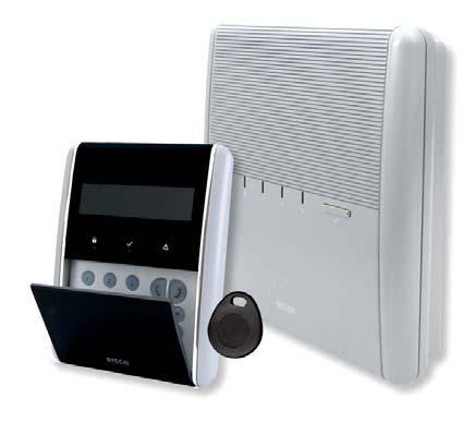
11 ON Agility Engineer Manual Chapter 2 Installing the Agility This chapter covers the installation procedures of the Agility, as follows: Agility Main Components, page 2 1 Mounting the Agility, page 2 2 Choosing the mounting location, page 2 2 Wall Mounting the Agility page 2 2 Connecting the Backup Battery, page 2 5 Connecting a telephone line to the Agility, page Error! Bookmark not defined. Connecting the Agility to Power Supply, page 2 6 Ground Connection, page 2 6 To connect to ground (Earth), page 2 6 DIP switch setting, page 2 8 SIM Card Installation, page 2 9 External Audio Unit, page 2 12 Agility Main Components The illustration below shows the internal components (when the Mounting Bracket is disassembled from the Back Panel) OPEN LOCK Figure 1: Agility Main Components 1. Installation Bracket 7. Transformer 13 RS 232 communication connector 2. Telephone Jacks 8. Back Panel 14. Battery compartment 3. Audio Unit terminals 9. SIM Card socket 15. Battery compartment cover 4. Ribbon flat cable jack 10. Ribbon flat cable 16. Battery fling leads 5. AC connection terminals 11. DIP Switches 17. Tamper switch 6. Fuse 12 PTM connector 18. IP Card network connector Page 2-1
12 Mounting the Agility IMPORTANT: The Agility has no user replaceable parts (for instance: power cord, fuse, battery, etc.) only certified engineers are allowed to replace faulty parts. Choosing the mounting location Before you mount the Agility, study the premises carefully in order to choose the exact location of the unit for the best possible coverage and yet easily accessible to prospective users of the alarm system. The mounting location of the Agility should be: Try to centrally locate the system between all the transmitters. Near an uninterrupted AC outlet. Near a telephone outlet. Far from sources of interference, such as: Direct heat sources Electrical noise such as computers, televisions etc. Large metal objects, which may shield the antenna. In a place where the alarm can be heard during Part Setting mode. Wall Mounting the Agility The Agility is comprised of two sub assemblies: Mounting bracket, Main unit which in its turn is comprised from: Front panel (not disassembled on a regular installation procedure) Back panel The mounting bracket is mounted on the wall, using the supplied proper hardware, as described below: To mount the Agility on the Wall: 1. Separate the Mounting bracket as follows: a. Release the Mounting bracket captive locking screws (1, Figure 2) located at the bottom of the unit by turning screws counterclockwise. 1 Figure 2: Mounting Bracket screws Page 2-2
13 b. Gently, pull up the Mounting bracket to a 45 angle and slide it down to release the Mounting bracket (2, Figure 3) from the two locking tabs (1, Figure 3) at the top of the unit. Note: Do not open the Mounting bracket to a larger angle in order not to break the two top tabs and not to tear up the ribbon flat cable connecting the power supply unit to the front panel (PCB). c. Disconnect the ribbon flat cable (3) from the power supply unit while leaving it connected to the Main panel. Figure 3: Mounting Bracket removal 2. Hold the Mounting bracket against the wall as a template and mark the locations for the mounting holes (5 mounting holes item 1, and an additional hole for securing the tamper protection bracket item 2, are available, see Figure 4). 3. Drill the desired mounting holes and place the screw anchors. Use the supplied 5 Philips pan head screws to attach the Mounting bracket to the wall (ST4.2 mm x 32 mm DIN 7981). 4. According to the location of the wall cables, route and insert the wires and cables via the cable s openings (3) (including AC cable and telephone cable), see figure If required, remove cable knockouts (5) to allow wire passage. 6. Anchor cables with dedicated hooks (4). Page 2-3
14 Figure 4: Wall Installation 7. Adjust the Tamper switch (using a flat screwdriver) according to your preferred configuration. a. Box and Wall configuration (see Figure 4, detail 6) Triggers the tamper when the box or the wall mounting are tampered. b. Box only configuration (see Figure 4, detail 7) Triggers the tamper when the box is tampered. Page 2-4
15 Connecting the Backup Battery The Agility has safety approved, sealed lead acid 6V, 3.3Ah rechargeable backup battery used in time of main power failure: Note: The battery is not supplied with the Agility. To insert the Backup battery: 1. Remove the battery compartment cover screw (see Figure 5,3) located at the top of the cover by turning screw counterclockwise and pull the Agility battery cover outward Figure 5: Battery Compartment a. Insert the battery into its place and connect the flying leads to the battery according to the correct polarity (Red +) (Black ). b. Return the battery compartment cover (after placing the battery in) and secure with locking screw. Note: The Agility Rechargeable battery should be charged for at least 24 hours. 2 Important: When replacing the battery be sure to buy the same type. Failure to comply with this instruction may result in damage to personnel and/or equipment. Dispose of used batteries according to the proper instructions. Page 2-5
16 Connecting the Agility to Power Supply Note: The Agility panel is permanently connected to the mains. The connection must be made according to your countryʹs local regulations. As a general guideline, connect the Live Neutral and Ground using a safety approved 3 wire 18AWG power cable (14 mm minimum diameter flexible PVC cable which complies with IEC60227). The cable should be brought to the Agility panel in a protective plastic conduit (diameter 16mm minimum). A 2 pole 16A circuit breaker and earth leakage protector should be used to disconnect the live conductor, and should be provided as part of the building installation. The Agility is powered by a safety approved 230VAC. 1. Remove the power supply unit cover (Figure 6, 1). 2. Connect the power wire (Safety approved, SVT, 18AWG, 0.75mm 2 ) to the power terminal located on the power supply unit (TB1) (Figure 6,2). Note: The power wire is not supplied with the Agility. 3. DO NOT connect the cable to the wall power supply at this point. Ground Connection Grounding provides a degree of protection against lightning and induced transients for any piece of electronic equipment that may, due to lightning or static discharge, experience permanent or general malfunctions. The ideal ground is considered to be a unified earth ground in which an 8 foot copper clad rod, located close to the existing power and telephone ground rods, is sunk several feet into the earth. Appropriate hardware and clamps are then used to electrically connect each of these rods together and then to the ground terminal of the device to be protected. It may be possible to use an existing electrical ground on the premises if one is close enough to the Agility. When connecting the ground wire, use a solid 14 gauge wire [or larger (numerically lower) size]. Keep this wire as short as possible and do not run it in conduit, coil it, bend it sharply, or run it alongside other wiring. If you must bend it or change its direction, it should have a radius of at least 8 inches at the point from which it is bent. If in doubt, you may want to enlist the help of a licensed electrician in matters concerning such grounding. To connect to ground (Earth): Connect between the Agility s ground terminal and an acceptable electrical ground connection for the lightning transient protective devices in this product to be effective. Important: Connecting to ground must be performed according to the local National Electrical Code. Page 2-6
17 2 TB1 ~ 1 Figure 6: Connecting AC Power wires Completing Installation 1. Set the DIP Switches according to the DIP Switch Setting section (see page 2 8). 2. Connect the ribbon flat cable between the main panel and the mounting bracket (J1). 3. Mount the Main unit to the mounting bracket using captive locking screws. 4. Plug in the power cable to the wall power outlet. 5. Power up the Agility. Page 2-7
18 DIP switch setting ON Factory Default DIP Switch 1 (E A): External Audio: Used to define if the voice of the Agility will go from the main unit or from an External Audio Unit. When the external unit is connected to the Agility the voice will be heard only through the Audio voice unit. ON: External Audio Unit is connected to the Agility OFF (Default): External Audio unit not connected to the Agility. DIP Switch 2 (DFLT): Default jumper: Used when performing the following 3 operations: 1. To return engineer, sub engineer and grand master codes to their default factory values. Set this DIP switch to ON, disconnect all power and then reconnect the power. 2. To manually erase wireless devices. Set this DIP switch to ON while power is connected. Execute a long press on the main unit button until a beep, indicating that all wireless devices have been erased, is heard. 3. To save or transfer data to or from the PTM device. ON: To transfer data from the PTM to the panel. OFF: To transfer data from the panel to the PTM. (Refer to Chapter 3 for these procedures.) DIP Switch 3 (PRGM): Enables loading local software updates to the Agility ON: software updates to the Agility can be loaded OFF (Default): software updates to the Agility can not be loaded DIP Switch 4 (BAT): Defines the Battery Discharge Protection option settings ON: Battery Discharge Protection is OFF: The battery may be totally discharged during continuous AC failure, thus battery replacement may be required (no deep discharge protection). Note: In this position the Agility will start to operate from a battery power supply whether it is connected to the Mains or not. OFF (Default): Battery deep Discharge Protection is ON: If an AC power outage occurs, the Agility automatically disconnects the battery when its backup battery voltage drops below 5.8 VDC, in order to prevent ʺdeep discharge that may damage the battery. Note: In this position the Agility will not start to operate from a battery power supply, unless connected to the Mains first. Page 2-8
19 Connecting a telephone line to the Agility Connect the system to a telephone line if the system configuration includes an internal modem. 1. Connect the incoming telephone line to the plug in CONN2 jack RJ11 (pins 2, 3) or to plug in CONN3 RJ31 (pins 4, 5) (see Error! Reference source not found.). 2. Connect any telephone on the premises to the plug in CONN2 jack RJ11 (pins 1, 4) or to plug in CONN3 RJ31 (pins 1, 8) (see Error! Reference source not found.). NOTE: To ensure line seizure capability, and comply with FCC part 68 regulations, the equipment must be connected directly to the Phone company lines (ʹCOʹ). Whether connected via RJ11, RJ31, the line port must be connected to the CO lines without any other phones or other telecom equipment between them. Other telecom equipment can be connected only after (in series) the alarm panel. CONN2 RJ11 CONN3 RJ31 Figure 7: Telephone Line Jacks Page 2-9
20 Connecting a network cable to the Agility If your Agility is equipped with an IP Card, you should connect the incoming network cable in order to enable IP Communication. 1. Separate the Agility from the mounting bracket. 2. According to the location of the network cable, route and insert the cable via the cable s openings (see figure 3). 3. If required, remove cable knockouts (5, Figure 3) to allow cable passage. 4. Connect the incoming network cable to the plug in. Page 2-10
. SIM Card LOCK OPEN LOCK OPEN LOCK OPEN 1. Slide down SIM card hatch.")
21 SIM Card Installation If your Agility is equipped with a GSM/GPRS module, you should insert a SIM card in order to enable communication through the GSM/GPRS network. 1. Insert the SIM into the dedicated SIM card slot located on the rear side of the back panel (See Figure 1: Agility Main Components). SIM Card LOCK OPEN LOCK OPEN LOCK OPEN 1. Slide down SIM card hatch. 2. Open the SIM card hatch. Insert SIM card into dedicated slot. Figure 8: SIM Card Insertion 3. Close the SIM card hatch. Slide up to lock. Important: Do not install SIM card while power is applied to the Agility. Do not touch SIM Card connectors! If doing so, you may release an electrical discharge that could damage the SIM card. 2. If a PIN code is required for the SIM card, the Agility will indicate a PIN code fault. To fix the fault, and thus enable the SIM card to operate properly, enter the PIN code number, located in the Communication > GSM parameters menu. Note: Ensure that you have the PIN code. Be aware that after three wrong attempts (recognized by the SIM card) to enter a PIN number, the SIM card will lock. You will have to contact your local cellular provider to unlock the SIM card. 3. If you want to disable the SIM PIN code you should follow the steps: a. Insert the SIM card into a standard GSM mobile phone. b. Insert the PIN code. c. Access the phone security menu and selecting PIN OFF. Once done, re test by switching the phone OFF, then switching ON. The PIN code should not be requested again. 4. Once the SIM card is placed it is recommended to test the operation of the SIM by conducting a call and testing the GSM signal strength. For more information refer to the programming menus of the GSM menu. Note: In some countries an SMS center phone number might be required in order to enable SMS messaging. This phone number is provided by the provider. Programming the SMS center phone into the SIM can be done using a standard GSM mobile phone or from the Agility keypad or configuration software. Page 2-11
22 External Audio Unit The Agility enables to connect an external Audio Unit instead of the internal unit in order to listen to the systemʹs audio messages in a distance from the main unit. In addition the unit enables you to talk into your premises. To connect the Audio unit: 1. Wire the Audio unit to the Agility as displayed in the Wiring Diagram described in Figure 9. The terminals for wiring the Audio Unit to the Agility are located on mounting bracket the Agility. 2. Set DIP Switch 1 (E A) (External Audio) to On position. Audio Unit Terminals on the Mounting Bracket External Audio Unit TMP GND AUX MIC SPKR AUDIO AUX COM IN OUT RED BLK TMP Figure 9: Wiring the External Audio Unit to Agility Page 2-12
23 Programming Methods Chapter 3 Engineer Programming There are 4 available options for programming the Agility: Configuration Software Wireless Keypad Engineer Keypad PTM Configuration Software A software application that enables you to program the Agility from a PC computer. It offers the following alternatives: Working locally, through a portable computer connected to the Agility via cable Working at a remote site, communicating with the Agility via a phone line, modem or IP address. For further information on programming the Agility via the Configuration software, refer to the Agility Configuration Software manual. Wireless Keypad The Agility can be fully configured via the wireless keypad. Notes: 1. The Agility can be programmed via any of the 2 way keypads in your system, but only using one keypad at a time for programming. 2. During engineer programming, the keypad will turn off after 4 minutes if no entry has been made to the keys. Press any button to restore the keypad. It will display the last parameter you were working on. To program the Agility via the Wireless Keypad, follow this procedure: 1. Perform system device allocation for the keypad (refer to page 3 4). 2. Press and enter the engineer code (default code is 0132). The keypad will sound a confirmation sound. Note: If a Grand Master code is required to confirm the engineer code, it should be entered at this stage after the engineer code. 3. Go to the Programming menu and press. Once the panel is in programming mode, the Agility main unit LEDs will flash simultaneously and a confirmation sound will be heard. Page 3-1
24 Note: The engineer can also program user activities by selecting the Activities menu instead of the Programming menu. Use the buttons to navigate between the menus. Engineer Keypad For those systems that do not have keypads, RISCO Group offers the Agility engineer a temporary keypad to be used as any Agility wireless keypad for configuring a system. An hour after exiting the programming mode the Engineer Keypad will be erased from the Agility memory or when power is lost to the system. To program the Agility via the Engineer Keypad, follow this procedure: 1. To allocate the Engineer Keypad into the system perform a short press on the main unit button. 2. Press the buttons on the keypad simultaneously until the following confirmation message is heard: Engineer Keypad Allocated. 3. Follow steps 2 and 3 of the wireless keypad (see page 3 1) to begin programming the system. PTM: Data Storing Device The PTM is a tiny circuit board into which the Agility panel can transmit a copy of the systemʹs configuration. The PTM stores this copy and can also transmit the configuration information back to the Agility panel. To transfer the system configuration from the panel to the PTM, follow this procedure: 1. Disconnect the flat cable and remove the Agility main unit from its wall bracket. Note: Make sure the battery is inserted into the main unit. 2. Make sure that Dipswitch 2 is set to OFF (default setting). 3. Place the PTM onto the 5 pin PTM located on the rear of the main unit PCB. The PTM LED will turn on. 4. Press the main unit button for 5 seconds. The PTM LED will flash quickly during the transmission of information to the PTM. 5. Once transmission is complete, the panel will sound a confirmation beep and the PTM LED will stop flashing and turn on steady. 6. Disconnect the PTM from the main unit. 7. Reconnect the flat cable to the main unit and replace the main unit in its wall bracket. Page 3-2
25 To transfer the system configuration from the PTM to the Agility panel, follow this procedure: 1. Disconnect the flat cable and remove the Agility main unit from its wall bracket. Note: Make sure the battery is inserted into the main unit. Make sure that the Default Enable system flag is on 2. Set Dipswitch 2 to ON. 3. Place the PTM onto the 5 pin PTM connector located on the main unit PCB. 4. All LEDS on the main unit will begin to flash simultaneously. The PTM LED will flash quickly during the transmission of information to the panel. 5. Once transmission is complete, the panel will sound a confirmation beep. Note: If the procedure fails the panel will make 3 short error beeps, and you will need to do the procedure again 6. Disconnect the PTM from the main unit. 7. Reset Dipswitch 2 to OFF. 8. Reconnect the flat cable to the main unit and replace the main unit in its wall bracket. Page 3-3
26 Wireless Device Allocation Each wireless device must identify itself to the system receiver. The following section describes the different ways to allocate all of your devices to the system in order to later configure each deviceʹs parameters The learning procedure between you re the wireless devices and the main unit can be performed either from the main unit, a wirless keypad or via the Configuration Software. Quick Allocation using the main unit button To perform quick allocation using the main unit button, follow this procedure: Note: To enable Quick Allocation mode the System bit ʺQuick Learnʺ should be enabled. 1. Set the main unit to Learn mode with a long press on the main unit button. Each LED will light up one after another. Note: The unit will sound each time you enter or exit the Learn mode. 2. Send a transmission from each device (refer to the Transmitters write message method table in section). The system will automatically identify each device according to different categories (for example: detectors, sounders, keypads, remote controls etc.) and enter each device and its default value into the unitʹs memory. Each device receives an index number from the system. 3. Exit the Learn mode with a short press on the main unit button. Allocation using the keypad It is possible to perform allocation via the keypad in two different ways: RF Allocation or by entering the device s serial code. To perform RF Allocation via the keypad, follow this procedure: 1. Go to the Engineer menus and select Programming Radio Device Allocation RF Allocation. The system immediately goes into Learn mode. 2. Send a transmission from the device. (See table: Transmitters write message method) 3. The main unit will acknowledge the transmission with a sound. When the system recognizes the device the keypad LCD will display the deviceʹs serial number and category. The system also automatically allocates the device the next available index number. To perform allocation via the keypad using a serial code, follow this procedure: 1. Go to the Engineer menus and select Programming Radio Device Allocation By Code. Enter the device s 12 digit serial code number. 2. The system automatically recognizes the device and allocates it the next available index number. The system will sound the device type that has been allocated and the place it has been allocated to. Page 3-4

27 Allocation using the Configuration Software It is possible to perform wireless device allocation via the configuration software in two different ways: RF Allocation or by entering the device s serial code. To perform RF allocation from the configuration software 1. Establish Communication between the main unit and the Configuration software. (For more information refer to the Configuration Software Manual) 2. Open the Activities > Radio Device Allocation screen. 3. Click on the button. This operation will set the main unit to Learn mode. The following message appears: 4. Send a transmission from the device. (See table below) 5. The main unit will acknowledge the transmission with a sound. When the system recognizes the device the Radio Device Allocation screen indicates that the status of allocation has been successful. The serial number, accessory type and the index number information will be displayed. The index number is automatically addressed by the system. Note: If required you can change the index number of the wireless device by selecting the required index number and pressing the button again. 6. To allocate an other wireless device click on the button and then repeat stages 3 7. To perform Code allocation from the configuration software 1. Establish Communication between the main unit and the Configuration software by selecting Communication>Connect from the main menu. (For more information refer to the Configuration Software Manual) 2. Open the Radio Device Allocation screen. In the Allocation area, enter the deviceʹs serial number. Note: The serial number can be found on the device itself and on its packaging. 3. Select the wireless device index number. Automatic means that the index number is automatically addressed by the system, 4. Press the button. Page 3-5
28 5. The main unit will acknowledge the transmission with a sound. When the system recognizes the device the Radio Device Allocation screen indicates that the status of allocation has been successful. Transmitters Write Message Method How to send a write message (transmission): Wireless Device Detector/Contacts 2 Way Keypad Sending Write Message Press the tamper switch for 3 seconds Press both keys and simultaneously for at least 2 seconds 1 Way Keypad Press the key twice 1 Way Key fob 2 Way Remote Control Smoke Detector Sounder Gas, CO detectors Press the button for at least 2 seconds Press both keys and simultaneously for at least 2 seconds Insert battery. Write message is send automatically within 10 seconds. Press the reset switch on the sounder. After a squawk is sounded at the sounder you have 10 seconds to press on the tamper switch for at least 3 seconds. Press the test button for 3 seconds 2 Panic Button Key fob Press both buttons for at least 7 seconds Page 3-6
29 Deleting Wireless Accessories Deleting all wireless devices can be done manually (from the main unit) or from the Configuration software. To manually delete all wireless accessories from the system: 1. Place Dip Switch 2 to ON position. 2. Press the main unit button until it sounds. 3. Replace Dip Switch 2 to OFF position. To delete a wireless accessory from the Wireless Keypad 1. Go to the Engineer menus and select Programming Radio Device Modification 2. Select the device category 3. Go to Parameters option. 4. Select the device index number 5. Go to Serial number option and type in Press. The device will be deleted To delete a wireless accessory from the system via the Configuration software: 1. Establish Communication between the main unit and the Configuration software (For more information refer to the Configuration Software Manual) 2. In the Radio Device Allocation screen in the Delete Accessories area enter the deviceʹs serial code and click the Delete button. To delete all wireless accessories from the system via the Configuration software: 1. Establish Communication between the main unit and the Configuration software by selecting Communication>Connect from the main menu. (For more information refer to the Configuration Software Manual) 2. In the Radio Device Allocation screen in the Delete Accessories area, click the Delete All button. When all accessories have been deleted the screen will indicate that deletion has been successful. Page 3-7
30 Page 3-8 Agility Engineer Manual
31 Chapter 4 Engineer Menus The following chapter describes the parameters and programming options of the system and radio devices. These parameters can be programmed via the Agility keypad or the configuration software by the engineer. Note: A note appears next to the parameters that can only be programmed via the configuration software. For more information regarding the installation and use of the configuration software refer to the Configuration Software manual. Using the Agility keypad keys The Agility two way keypad contains three LED indicators, an LCD display and a variety of keys. The following table describes the typical uses of the keys when in programming mode. Keys Description The numerical keys on the keypad are used as quick keys, a numerical sequence used as a shortcut to program an option. To program the system using Quick keys: 1. Access the engineer menus (see below) and select the relevant main menu option. 2. Press the quick keys in sequence to locate the parameter and press. Numerical keys are also used to input the numeric codes that may be required for setting, unsetting, or used to activate specific functions. Exits from the current menu and returns to Normal Operation mode Terminates commands and confirms data to be stored Used to browse through the menu: Scrolls up a list or moves the cursor Changes data Page 4-1
32 Accessing the Engineer Menus To access the engineer menus via the Agility keypad, follow this procedure: Press the key to activate the keypad. Enter the engineer code 0132 (default code). Note: If the Authorize Engineer system bit is defined as YES, a Grand Master code is required to authorize the engineer to enter the programming mode. In this case the Grand Master code should be entered after the engineer code via the Grand Master menu Activities Authorize Engineer. The following menu appears displaying a list of all the engineer menus: 1) Programming 2) Testing 3) Activities 4) Follow Me 5) Clock 6) Event Log Using the keys to select the options. Programming Menu All the system parameters are programmed by the engineer via the programming menu. After accessing the engineer menus, select the 1) Programming option. The following list appears: 1. System 2. Radio Devices 3. Codes 4. Communication 5. Audio 6. Exit 1. Programming: System Menu The System menu provides access to parameters that are used for programming configuration settings applicable to the entire system. The System menu is divided into the following sub menus: 1. Timers 2. Controls 3. Labels 4. Sounds Page 4-2
33 5. Settings 6. Service Information 1.1 Timers The Timers menu contains parameters that specify the duration of an action. System: Timers Parameter Default Range Exit/Entry Delay 1 The amount of time before the system is set/unset. Usually used on front entrance door. Entry Delay 1 30 sec sec Duration of entry delay 1 before the system is unset. Exit Delay 1 45 sec sec Duration of exit delay 1 before the system is set. Exit/Entry Delay 2 The amount of time before the system is set/unset. Usually used to back door. Entry Delay 2 45 sec sec Duration of entry delay 2 before the system is unset. Exit Delay 2 60 sec sec Duration of exit delay 2 before the system is set. Bell Timeout Duration of the sounder during alarm. Bell Delay 04 min min 00 min min The time delay before a sounder sound is produced after triggering an alarm. AC Off Delay 30 min min In the case of a loss of AC power, this parameter specifies the delay period before reporting the event or operating the Programmable Output. If the delay time is set to zero, there will be no delay period. Jamming Time None None, 10, 20 or 30 sec Specifies the period of time that the systemʹs receiver tolerates unwanted radio frequencies capable of blocking (jamming) signals produced by the systemʹs transmitters. Once the specified time is reached, the system sends a report code to the alarm receiving center or activates a local sounder, depending on the Audible Jamming system control. NONE: No jamming will be detected or reported. Page 4-3
34 System: Timers Parameter Default Range RX Supervision 3 hours 0 7 hours Specifies how often the system expects to get a signal from the systemʹs transmitters. If a signal from a zone is not received during the specified time the zone will be regarded as lost, the system will send a report code to the alarm receiving center, and the system status will be ʺNot Readyʺ. Notes: 0 hours disables supervision It is recommended to set the supervision time to a minimum of 3 hours TX Supervision min Specifies how often the system generates a supervision request to a bi directional wireless device. If any of the accessories does not respond to the request, at least once, during the RX Supervision time, the system will regard the accessory as Lost. Note: The device will generate the supervision message according to the time defined. Important: The RX Supervision time should be higher than the Tx Supervision time in order to eliminate false lost event. Redial Wait 30 sec sec The number of seconds between attempts at redialing the same phone number. Applies to both the ARC Retries and FM Retries parameters. Note: Used for both PSTN and GSM. Swinger Limit Shutdown times A swinger is a repeated violation of the same zone, often resulting in a nuisance alarm and usually due to a malfunction, an environmental problem, or the incorrect installation of a detector or sensor. This parameter specifies the number of violations of the same zone reported during a single set period, before the zone is automatically omitted. Note: 00 to disables the swinger shutdown No Activity hours Determines the time limit for reception of signals from sensors used to monitor the activity of sick, elderly or disabled people. If no signal is received from a zone defined with the ʺNo Activityʺ feature at least once within the defined time limit, a no activity alert can be send to Follow Me destination, a local message can be heard and a report to Monitoring Station can be defined to be send. Options: 0 =this parameter is inactive. Page 4-4
35 1.2 Controls The Control menu contains parameters that control specific system operations. System: Controls Parameter Basic programming Quick Set YES: Eliminates the need for a user code when setting (Full or partial) the system by a keypad or 2 way remote control. NO: A valid user code is required for setting using a keypad or remote control. Allow Omit Default YES: Permits zone omitting by authorized system users after entering a valid user code. NO: Zone omitting is NOT permitted. Quick Status YES: A user code is not required before pressing the status key/button on your wireless keypad or bi directional remote control. NO: A user code is required to activate the status key. False Code Fault YES: A false code report is sent to the alarm receiving center after five successive attempts at setting or unsetting in which an incorrect user code is entered. No alarm sounds at the premises, but a fault indication appears. The wireless keypad will be locked for 30 minutes. NO: A local alarm is sounded at the premises. Sounder Squawk YES: Setting or unsetting the system using a remote control, wireless keypad or a keyswitch produces a brief ʺchirpʺ and activates the strobe as follows: One chirp indicates the system is set (also when setting with a keypad). Two chirps indicate the system is unset. Four chirps indicate the system is unset after an alarm. NO: No ʺchirpʺ is produced. Audible Panic YES: The sounders operate when a ʺPolice Alarmʺ is initiated at the keypad (if defined), the remote control or when a panic zone is activated. NO: No sounder operation occurs during a ʺPanic Alarm,ʺ making the alarm truly ʺsilentʺ (Silent Panic). Note: The system always transmits a panic report to the alarm receiving center. YES YES YES YES YES NO Page 4-5
36 System: Controls Parameter Buzzer Bell Default YES: If an alarm occurs when the system is set in the Part Set mode, a buzzer sounds for 15 seconds before the sounders operate. NO: An alarm in the Part Set mode causes sounders to operate simultaneously. Audible Jamming Relates to the Jamming Time parameter. YES: Once the specified time is reached, the system activates the sounder and sends a report code to the alarm receiving center. NO: Once the specified time is reached the sounders do not operate. Exit Beeps at Part Set Determines whether the system will sound beeps during exit time in Part Setting. YES: Exit beeps will sound NO: Exit beeps will not sound Forced Device Setting YES: Setting a partition, using a remote control or key switch can be performed with violated (not ready) zones in the system. Any violated (not ready) zone(s) in the partition will be omitted automatically. The partition is then ʺforce set,ʺ and all intact zones are capable of producing an alarm. NO: The partition cannot be set until all violated (not ready) zones are secured. Set Pre warning Related to auto Set/Unset operation. YES: For any partition(s) set up for Auto Setting, an audible Exit Delay (warning) countdown will commence 4.25 minutes prior to the automatic Setting. During this period, Exit Delay beeps will be heard. You can enter a valid User Code at any time during the countdown to delay the partitionʹs automatic Setting by 45 minutes. When an ʺAuto Setʺ partition is unset, as described above, it can no longer be automatically set during the current day. The extended 4.25 minutes warning does not apply to automatic Partial Setting. NO: Auto Setting for any programmed partition(s) takes place at the designated time. The programmed Exit Delay period and any audible signal occur as expected. NO NO YES YES YES Page 4-6
37 System: Controls Parameter Default Enable Default This option contains parameters that relate to what happens to the Engineer, Sub Engineer and Grand Master codes if the Main Panelʹs DEFAULT Dip Switch 2 is in place when power to the Main Panel is switched off and then on. YES: The Engineer, Sub Engineer and Grand Master codes will return to the original, factory default values. NO: The Engineer, Sub Engineer and Grand Master codes will NOT return to the original, factory default values by an unauthorized user. Main Button: Status Y/Talk N The Agility enables the ARC to perform Listen In and Talk functions in order to verify a cause of event or to guide someone in distress. The Main Button: Status Y/Talk N parameter determines the function of the button on the surface of the main unit to enable Listen In and Talk. YES: Status button The system will relay the system status. NO: Service call button The system dials the Monitoring Station to establish 2 way communication. Quick Learn Enables the button on the surface of the main unit to perform quick allocation of wireless devices. (See Chapter 3 System Device Allocation: Manual Setup) YES: Quick learn mode is enabled. Long press on the main unit button will start Learn mode. The LEDs on the main unit will start flashing one after the other NO: Quick learning mode is disabled. The main unit button is not in Learn mode. Advanced programming Area Changes the system operation to Area instead of Partition, which then changes only the operation of a common zone. YES: When selected, the following points are relevant: A common zone will be set after any partition is set. A common zone will be unset only when all partitions are unset. NO: When selected, the following points are relevant: A common zone will be set only when all partitions are set. A common zone will be unset when any partition is unset. NO YES YES YES Page 4-7
38 System: Controls Parameter Global Follower YES: Specifies that all zones (that are programmed to follow an Exit/Entry Delay time) will follow the Exit/Entry Delay time of any set partition. NO: Specifies that all zones (that are programmed to follow an Entry Delay time) will follow the Entry Delay time of only the partitions to which they are assigned. Summer/Winter Default YES: The system automatically sets its time of day clock one hour ahead in the spring (on the last Sunday in March) and one hour back in the Autumn (on the last Sunday in October). NO: No automatic time accommodation is made. 24 Hour Omit NO YES: It is possible for the user to omit a 24 hour zone. NO: It is not possible for the user to omit a 24 hour zone. Technician Tamper YES: It is necessary to enter the Engineer Code to reset a Tamper alarm. Therefore, resetting a Tamper alarm requires the intervention of the alarm company. However, the system can still be set. NO: Correcting the problem resets a Tamper alarm, requiring no alarm company help. Technician Reset YES: It is necessary to enter the Engineer Code to reset an alarmed partition after it has been unset. This requires the intervention of the alarm company. Note: Before the Ready LED can light all zones within the partition must be secured. NO: Once an alarmed partition is reset the Ready LED lights when all zones are secured. Engineer Tamper YES: After a Tamper alarm, the system is not ready to set. This requires the intervention of the alarm company. NO: After a Tamper alarm is restored the system is ready. Low Battery Set YES YES: Allows setting of the system when a low battery condition is detected in the main unit. NO: Setting the system is disabled when a low battery condition is detected. NO NO NO NO NO Page 4-8
39 System: Controls Parameter Sounder Pre Alarm Default Specifies if the system will send a pre alarm message to the sounder while an entry delay starts. YES: The system sends a pre alarm signal to the sounder at the beginning of the entry delay. If the sounder does not receive a cancellation signal from the system at the end of the entry time, the sounder goes into alarm. NO: Pre Alarm disabled Bell 30/10 YES: The sounders cease to sound for 10 seconds after each 30 seconds of operation. NO: The sounders operate without interruption. Fire Alarm Pattern YES: During a fire alarm, the sounders produce a pattern of 3 short bursts followed by a brief pause. NO: During a fire alarm, the flow of sounds produced by the sounder is a pattern of 2 seconds ON, then 2 seconds OFF. IMQ YES: Causes the following parameters to function as follows: Auto Set Omit: If there is an open zone during the Auto Set process, the system will be set, and a silent alarm will be activated (unless the open zone is closed). A programming output defined as Auto Set Alarm is activated. A programming output defined as Zone Loss Alarm is activated NO: Causes the following parameters to function as follows: Auto Set Omit: If the Auto Set programming sets the system and there is an open zone during the auto set, the system will omit the open zones and set the system. A programming output defined as Auto Set Alarm is deactivated. A programming output defined as Zone Loss Alarm is deactivated. Disable Incoming Call This parameter is used to disable all incoming calls trying to come in via the voice channel (PSTN or GSM). YES: Incoming calls from voice channel are disabled. NO: Incoming calls from voice channel are enabled. Note: Incoming data call via the GSM data channel is still enabled. NO NO NO NO NO Page 4-9
40 System: Controls Parameter Communication ARC Enable Default YES: Enables communication with the Central Station to report alarms, fault, and supervisory events. NO: No communication with the Central Station is possible. Choose NO for installations that are NOT monitored by a Central Station. Configuration Software Enable YES YES: Enables communication between the alarm company and the system using the Configuration software. This enables modifying an installationʹs configuration, obtaining status information, and issuing Main Panel commands, all from a remote location. NO: Disables communication, as detailed above. FM Enable YES: Enables Follow Me communication. If both the ARC phones and the FM phones are defined, the system will first call the ARC phones and then the FM phones. NO: Disables Follow Me communication. EN programming Authorize Engineer This option limits the Engineer and Sub engineer authorization to access the programming menu. YES: A Grand Master code is required to authorize the engineer to enter the programming mode for 1 hour. NO: The Engineer does not need an authorization code. Override Fault Specifies if the system/partition can be set when there is a fault in the system. YES: The system will set even if there is a fault in the system. NO: When the user starts the setting process and there is a system fault, the user must confirm that he is aware of all faults before continuing with the Setting process. This is done via the User menu Activities Omit Fault. The system will not set during forced setting if a fault occurred in the system YES YES NO YES Page 4-10
Important Notice This guide is delivered subject to the following conditions and restrictions:
 Installer Manual Important Notice This guide is delivered subject to the following conditions and restrictions: This guide contains proprietary information belonging to RISCO Group. Such information is
Important Notice This guide is delivered subject to the following conditions and restrictions:
 Engineer Manual Important Notice This guide is delivered subject to the following conditions and restrictions: This guide contains proprietary information belonging to RISCO Group. Such information is
Installation and Programming Manual
 Installation and Programming Manual Installation and Programming Manual (Ver 4.31 and above) Table of Contents Chapter 1: Introducing WisDom...1-1 What is the WisDom?...1-1 WisDom Architecture and Capabilities...1-2
Summary of Keypad Main User Commands
 User Manual Summary of Keypad Main User Commands Full Set Code > Part Set Code > System Unset Silence an Alarm Partition Full Set Partition Part Set Code> Code> Code > > Partition No. > Code > > Partition
EVO192 v3.0 Fire and Burglary What s New
 EVO192 v3.0 Fire and Burglary What s New Compatibility: EVO192 v3.0 TM50 v1.31 K641 v2.41 Overview: CP-01 Compliancy Wiring Diagram The following sections/options have been added to the EVO192 panel. They
All-In-One Wireless Security System V3.2 Programming Guide. Model # MG6130 / MG6160
 All-In-One Wireless Security System V3.2 Programming Guide Model # MG6130 / MG6160 We hope this product performs to your complete satisfaction. Should you have any questions or comments, please visit www.paradox.com
Contents. Glossary
 Contents Glossary ------------------------------------------------------------------------------------------------------ 6 1. Introduction to the IDS 1632 -------------------------------------------------------------
Watchguard WGAP864 User Manual
 Watchguard WGAP864 User Manual v1.0 Issued September 2016 1 2 Table of Contents Glossary... 5 1. Introduction to your Watchguard WGAP864... 6 2. Before Operating your Alarm System... 6 3. Understanding
External Wireless Sounder
 External Wireless Sounder Model: WL RWS401 Installation and Programming Instructions Table of Contents Introduction... 3 Operational Functions... 3 Alarm / Tamper Indication... 3 Low Battery Indication...
A1UL PERS. Personal Emergency Response System. For Technical Support Please Contact Your Service Provider Or Distributor
 A1UL PERS Personal Emergency Response System TABLE OF CONTENTS 1. READ THIS FIRST... 1 2. SYSTEM OVERVIEW.. 1 3. COMPONENTS 2 4. UNIT OPERATION! Standby Mode.. 3! Emergency Activation. 3! Answering Incoming
External Wireless Sounder
 External Wireless Sounder WL S50 Installation and Programming Instructions 2 Wireless Sounder Instructions Table of Contents Introduction... 4 Operational Functions... 4 Alarm / Tamper Indication...4 Low
PERMACONN PM1030 Includes DI300. Installation Manual
 PERMACONN PM1030 Includes DI300 Installation Manual Radio Data Comms Unit 5/20-30 Stubbs Street Silverwater NSW 2128 Telephone: 02 9352 1777 Facsimile: 02 9352 1700 Introduction The PERMACONN system provides
All-In-One Wireless Security System V1.0. Model #: MG Reference and Installation Manual
 All-In-One Wireless Security System V1.0 Model #: MG-6060 Reference and Installation Manual Table of Contents Introduction... 3 About Magellan and this Manual... 3 Conventions... 3 Specifications... 3
JA-63 Profi User manual
 JA-63 Profi User manual Contents: 1 Limited warranty... 2 2 Indicators... 3 3 Controlling the system... 4 3.1 Arming... 5 3.2 Disarming... 6 3.3 Panic Alarm... 6 3.4 To stop ALARM... 6 3.5 Home arming...
3 User s settings. 3.3 Internal clock setting
 2.9 Subsystem arming In a large building a sub control panel can be enrolled to the JA-63. The subsystem reports all alarms and failures to the main system. The installer can program if the systems will
All-In-One Wireless Security System V1.0. Model #: MG-6060
 All-In-One Wireless Security System V1.0 Model #: MG-6060 Reference and Installation Manual DRAFT Table of Contents Introduction... 5 About Magellan and this Manual... 5 Conventions... 5 Specifications...
User s Guide. SUB-MA7240O-0001.OG.Solution doc. Created: 6/05/03. Last Updated: 23/09/03. MA7240AO-0001 Version 1.0
 User s Guide SUB-MA7240O-0001.OG.Solution40-111.doc Created: 6/05/03 Last Updated: 23/09/03 MA7240AO-0001 Version 1.0 2 Table Of Contents User List...6 Quick Reference..7 Features...7 Keypad User's Guide...8
600 Range Dialer Installation Manual. Version 1.0
 600 Range Dialer Installation Manual Version 1.0 The information contained is supplied without liability for any errors or omissions. No part may be reproduced or used except as authorised by contract
Honeywell Control Panels FOR RESIDENTIAL AND COMMERCIAL INSTALLATIONS. Feature Charts
 Honeywell Control Panels FOR RESIDENTIAL AND COMMERCIAL INSTALLATIONS Feature Charts Control Panels FEATURE CHART LYNX Plus (L3000) (Supported Feature) (Not Supported) N/A (Not Applicable) LYNX Touch (L5210)
BURGLAR ALARM PANEL BS-468
 BURGLAR ALARM PANEL BS-468 Contents 1. Description... 3 2. Instructions for the user... 4 2.1Basic operations... 4 Complete system.... 4 Split system.... 4 2.2 Armed system indication... 5 2.3 Advanced
1. Introduction. 2. Product overview
 1. Introduction The AG400011 GSM Alarm panel is a control panel that is compatible with other H-net security devices from Everspring, such as wireless sensors, remote keyfobs, tags, and keypad. With this
X64 Wireless Training
 X64 Wireless Training IDS Contents 1 Contents Features 3 Wireless Hardware 4 IDS & Duevi integration PCB 5 LED operation 5 Wireless Device Hardware setup 6 Location 260 7 LED Keypad Instructions 7 Adding
Testing the System. Battery Test. Dialer Test. Fire Drill Test (Code + [#] + 69) One-Man Fire Walk-Test (Code + [#] + 68)
![Testing the System. Battery Test. Dialer Test. Fire Drill Test (Code + [#] + 69) One-Man Fire Walk-Test (Code + [#] + 68)](/thumbs/79/79864325.jpg "Testing the System. Battery Test. Dialer Test. Fire Drill Test (Code + [#] + 69) One-Man Fire Walk-Test (Code + [#] + 68)") F A 1 7 0 0 c Testing the System Battery Test When AC power is present, the FA1700C runs a brief battery test every 60 seconds to determine if there is a battery connected, and runs an extended battery
F A 1 7 0 0 c Testing the System Battery Test When AC power is present, the FA1700C runs a brief battery test every 60 seconds to determine if there is a battery connected, and runs an extended battery
MG Partition 64-Zone Wireless Console with GPRS/GSM Version 1.6. Section Programming Guide
 MG6250 2-Partition 64-Zone Wireless Console with GPRS/GSM Version.6 Section Programming Guide Things You Need to Know About this Programming Guide The MG6250 All-in-one Wireless Console can be programmed
Galaxy Flex V3. User Guide. Honeywell Security. This user manual is located at
 Galaxy Flex V3 User Guide Honeywell Security This user manual is located at www.eaglesecuritysolutions.co.uk Contents Introduction... 5 Controlling your alarm system... 6 Users... 6 Panel control... 6
Fire Burglary Instruments Inc. XL-2G Gold Control/Communicator Installation Training Seminar Rev. 5/96
 Fire Burglary Instruments Inc. XL-2G Gold Control/Communicator Installation Training Seminar Rev. 5/96 XL-2G Gold Product Overview 7 Zones (6 programmable + panic or keyswitch zone) Fast Loop Response
Independent Zone Control (I.Z.C.)
") Operation and Installation Guide Independent Zone Control (I.Z.C.) DELAYED INSTANT ARMED 1 2 3 4 7 5 6 8 9 * * fi Radionics R D279A Operation & Installation Guide 46456B Page 2 Copyright 2000 Radionics
Operation and Installation Guide Independent Zone Control (I.Z.C.) DELAYED INSTANT ARMED 1 2 3 4 7 5 6 8 9 * * fi Radionics R D279A Operation & Installation Guide 46456B Page 2 Copyright 2000 Radionics
Wolf Guard Touch Keypad GSM Wireless alarm system User s Manual
 Wolf Guard Touch Keypad GSM Wireless alarm system User s Manual Page 1 Warning Do not remove the front or back cover of the unit and keep it intact. There are no parts inside this unit that can be repaired
USER GUIDE. PowerMaster-10 G2 Fully supervised wireless alarm control system.
 USER GUIDE PowerMaster-10 G2 Fully supervised wireless alarm control system www.visonic.com PowerMaster-10/30 G2 Version 17 User's Guide Table of Contents 1. Introduction... 3 Preface... 3 Overview...
Installation and Programming Manual
 Installer Manu Installation and Programming Manual Important Notice This guide is delivered subject to the following conditions and restrictions: This guide contains proprietary information belonging to
Version 1.03 January-2002 USER S MANUAL
 Version 1.03 January-2002 1 USER S MANUAL 2 Version 1.03 January-2002 System Details CUSTOMER:...... PHONE:... FAX:... INSTALLED BY:...... PHONE:... FAX:... MAINTENANCE & SERVICE:...... PHONE:... FAX:...
MG5000 V2.4 MG5050 V2.4 SP5500 V2.4 SP6000 V2.4 SP7000 V2.4. Programming Guide
 MG5000 V2.4 MG5050 V2.4 SP5500 V2.4 SP6000 V2.4 SP7000 V2.4 Programming Guide We hope this product performs to your complete satisfaction. Should you have any questions or comments, please visit www.paradox.com
GLOBAL. InstallatIon & operation manual
 InstallatIon & operation manual INDEX 1. INTRODUCTION... 5 2. FEATURES AND FUNCTIONS 2.1 Reporting Options... 2.2 Interfaces... 2.3 Programming... 2.4 Indicators and Controls...... 6 6 6 6 6 3. INSTALLATION...
Security System. User Guide for the LED Command Center
 Security System User Guide for the LED Command Center National Security Systems Inc (800)457-1999 MY SECURITY COMPANY IS: CALL BEFORE TEST: THIS SECURITY SYSTEM IS CONNECTED TO TELEPHONE NUMBER: THE SECURITY
TYDOM 315. * _Rev.2* GSM domotics transmitter. 1. Presentation
 TYDOM 5 GSM domotics transmitter ) Présentation. Presentation Delta Dore hereby declares that the equipment complies with the essential requirements and other relevant provisions of the R&TTE Directive
Beacon 200 Gas Monitor Operator s Manual. Part Number: RK Released: 6/6/08
 Beacon 200 Gas Monitor Operator s Manual Part Number: 71-2102RK Released: 6/6/08 Table of Contents Chapter 1: Introduction.................................................3 Overview.............................................................3
ATS1235 Advanced Wireless DGP on 868 MHz AM Installation Sheet
 ATS1235 Advanced Wireless DGP on 868 MHz AM Installation Sheet EN 1 2 1 3 2 4 1 5 12V 6 2 0V D+ D- CON3 7 CON1 ON 3 1 2 3 4 1234 8 3 4 1 0 ON 1 2 3 4 METAL METAL Address 1 1 0 ON 1 2 3 4 Address 2 2011
Digiplex System V2.14 / V2.2ACC. Control Panel Programming Guide
 Digiplex System V2.14 / V2.2ACC Control Panel Programming Guide Table of Contents Getting Started...2 What Do I Do First?...2 How Do I Program the Control Panel?...2 Single Digit Entry Method...2 Multiple
User Guide PowerMaster-10/ PowerMaster-30 Fully supervised wireless alarm control system
 Fully pervised ireless alarm control tem Fully pervised ireless alarm control rol tem Fully pervised User Guide PowerMaster-10/ PowerMaster-30 Fully supervised wireless alarm control system PowerMaster-10
JA-63 PROFI Alarm System MGK55402
 Contents: 1 Architecture of the control panel... 4 2 Control panel installation... 4 2.1 Mains supply connection... 5 3 Antenna for the radio module... 5 3.1 Rubber rod antenna used in the control panel...
Installation Instructions
 NX-148E-RF LCD Touchpad with Receiver 466-2198C February 2006 Copyright 2006, GE Security Inc. Contents Product summary 1 Installation 1 Transmitter programming 2 Touchpad programming 5 Reference tables
MOBILE CALL GSM Alarm System User s Manual
 MOBILE CALL GSM Alarm System User s Manual Profile For a better understanding of this product, please read this user manual thoroughly before using it. Contents Function Introduction (3) Alarm Host Diagram
80 CHANNELS WIRELESS RECEIVER WITH LCD DISPLAY M1.1.1-Hx.x-F1.1-ENG [AN] [SPV] MADE IN ITALY INSTALLATION AND USE MANUAL
![80 CHANNELS WIRELESS RECEIVER WITH LCD DISPLAY M1.1.1-Hx.x-F1.1-ENG [AN] [SPV] MADE IN ITALY INSTALLATION AND USE MANUAL](/thumbs/72/67367199.jpg "80 CHANNELS WIRELESS RECEIVER WITH LCD DISPLAY M1.1.1-Hx.x-F1.1-ENG [AN] [SPV] MADE IN ITALY INSTALLATION AND USE MANUAL") RX808-LCD 80 CHANNELS WIRELESS RECEIVER WITH LCD DISPLAY 14.12-M1.1.1-Hx.x-F1.1-ENG [AN] [SPV] MADE IN ITALY INSTALLATION AND USE MANUAL WARNINGS Installation: This device must be installed only by qualified
RX808-LCD 80 CHANNELS WIRELESS RECEIVER WITH LCD DISPLAY 14.12-M1.1.1-Hx.x-F1.1-ENG [AN] [SPV] MADE IN ITALY INSTALLATION AND USE MANUAL WARNINGS Installation: This device must be installed only by qualified
M2M Services Ltd. RControl Alarm - Installer Manual V 1.0
 M2M Services Ltd. RControl Alarm - Installer Manual V 1.0 Content Content... 2 Wiring the power supply module... 3 Wiring a siren... 3 SMARTEnroll self-learning zones... 3 Wireless keyfobs... 3 Supported
USER GUIDE HARDWIRED CONTROL PANELS
 USER GUIDE HARDWIRED CONTROL PANELS Scantronic Contents 1. Introduction... 3 The Alarm System... 3 The Keypads... 3 The 725r Remote Setting Device... 6 About This Guide... 6 2. Everyday Operation... 7
NetworX Series. NX-8 Commercial Fire Panel Installation and Startup
 NetworX Series NX-8 Commercial Fire Panel Installation and Startup 2004 GE Security All rights reserved. Printed in the United States of America. These instructions do not purport to cover all details
To activate using remote control: press [ ] key once. To activate using keyboard: on panel keyboard [ ] keys once.
![To activate using remote control: press [ ] key once. To activate using keyboard: on panel keyboard [ ] keys once.](/thumbs/93/113878877.jpg "To activate using remote control: press [ ] key once. To activate using keyboard: on panel keyboard [ ] keys once.") Table of Content 1.1General Description----------------------------------------------------------------------2 2.2System Setup-----------------------------------------------------------------------------3
Table of Content 1.1General Description----------------------------------------------------------------------2 2.2System Setup-----------------------------------------------------------------------------3
SMS8 Alarm Control Panel
 SMS8 Alarm Control Panel 8 Zone Alarm Control Panel with LCD Keypad, Inbuilt Dialler for Back to Base Monitoring and SMS Messaging. Easy Operation Dialler SMS Messaging I n s t r u c t i o n s N517 Code
Wireless Keypads LKP(E)S8M Series
S8M Series") Wireless Keypads LKP(E)S8M Series User manual Contents Congratulations on your purchase of this Honeywell wireless keypad. To make the best out of your equipment we advise you to read this manual carefully.
Wireless Keypads LKP(E)S8M Series User manual Contents Congratulations on your purchase of this Honeywell wireless keypad. To make the best out of your equipment we advise you to read this manual carefully.
USER S MANUAL. Profile. MOBILE CALL GSM Alarm System
 MOBILE CALL GSM Alarm System USER S MANUAL System disarmed 00/00/00 00:00 ARM STAY CALL 1 2 3 4 5 6 7 8 9 Power Set Signal Alarm SOS ESC 0 ENTER Profile For a better understanding of this product, please
IDS816 User Manual H Issued January 2009
 1 Contents Glossary-------------------------------------------------------------------------------------------------------------------6 1. Introduction to the IDS 816---------------------------------------------------------------------------7
Solution Ultima Series Operators Manual ISSUE 1.00
 Solution Ultima Series Operators Manual ISSUE 1.00 Solution Ultima Series Operators Manual Copyright 1998 by, SYDNEY, AUSTRALIA Document Part Number MA488O DOCUMENT ISSUE 1.00 Printed 16 February 1999
PERS-3600 PERSONAL EMERGENCY REPORTING SYSTEM INSTALLATION & OPERATION INSTRUCTIONS
 PERS-600 PERSONAL EMERGENCY REPORTING SYSTEM BY BY INSTALLATION & OPERATION INSTRUCTIONS (760) 8-7000 USA & Canada (800) -587 & (800) 9-0 Toll Free FAX (800) 68-0 www.linearcorp.com CONTENTS CONTROL AREA
SA 2650 Kit User Manual
 SA 2650 Kit User Manual Table of Contents 1. System Installation Planning 1 2. Device Introduction 3 3. Getting Started 6 4. System Default Setting 10 5. Connect2Home Application 11 6. System Information
NetworX NX-548E Receiver Installation Instructions
 NetworX NX-548E Receiver Installation Instructions Content Introduction... 1 Internal mounting... 1 External mounting... 2 Wiring... 3 DIP switch settings... 3 Power up... 3 Programming... 4 Testing and
Integrated Security Solutions
 Integrated Security Solutions Table of Contents Control Panels 4 Keypads 8 Communication Modules 16 I/O Expanders 20 Door Control 24 Home Automation 25 RF Receivers 26 3 Our integrated security solutions
GSM Alarm System. User s Manual. Profile. MOBILE CALL GSM Alarm System
 MOBILE CALL GSM Alarm System GSM Alarm System System disarmed 11/26/2013 User s Manual Profile For a better understanding of this product, please read this user manual thoroughly before using it. CONTENTS
8 plus and16 plus. User s Guide * # ent. esc GALAXY 16+ V2.XX TUE 30 JUN. IU ZST 962 Issue 2. A u B u
 8 plus and16 plus User s Guide GALAXY 16+ V2.XX 06.22 TUE 30 JUN 1 2 3 4 5 6 7 8 9 0 * # A u B u ent esc IU1-0018 ZST 962 Issue 2 Contents INTRODUCTION... 1 Glossary of Terms... 3 KEYPAD INFORMATION...
AXI LED USER MANUAL (REV. 1.0)
") Security & Home Automation System AXI LED USER MANUAL (REV. 1.0) CONTENTS PREFACE FEATURES LED KEYPAD OUTLOOK 1.0 LIGHT INDICATION 1 2 4 6 CHAPTER 1: ALARM SYSTEM CONTROL 1.0 USING LED KEYPAD 1.0.1 ARMING
Security & Home Automation System AXI LED USER MANUAL (REV. 1.0) CONTENTS PREFACE FEATURES LED KEYPAD OUTLOOK 1.0 LIGHT INDICATION 1 2 4 6 CHAPTER 1: ALARM SYSTEM CONTROL 1.0 USING LED KEYPAD 1.0.1 ARMING
Table of Contents. Appendix A Special Characters 31
 Table of Contents Introduction 2 Section 1: General System Operation 3 1.1 Getting to Know Your System... 3 1.2 How to Arm... 4 1.3 Alternate Arming Methods... 5 1.4 Disarming... 6 1.5 Alarm Memory...
Ref.1067/032 Ref.1067/042
 DS1067-033A Mod. 1067 LBT8631 BUS CONTROL PANEL 8/32 INPUTS Ref.1067/032 Ref.1067/042 USER MANUAL TABLE OF CONTENTS 1 PREFACE... 5 2 COMMAND DEVICES... 6 2.1 1067/021 DISPLAY KEYPAD... 6 2.2 ELECTRONIC
System. For a better understanding of this product, please read this user manual thoroughly before using it.
 GSM Alarm System User s Manual For a better understanding of this product, please read this user manual thoroughly before using it. Chapter 1. Features Chapter 2. Control Panel Introduction Chapter 3.
Installation Manual Premier 412/816/832. Issue 10
 Installation Manual Premier // Issue 0 Premier // Installation Manual 5. Operating the System Introduction Before attempting to operate the alarm system ensure you have familiarised yourself with all the
Alarm Control Panel WIC-16Z4P WIC-5Z2P. User Instructions
 WIC-16Z4P WIC-5Z2P User Instructions Page : 2/14 INDEX # Function Page 1 Add a New User Code 11 2 Arm or Disarm All Areas or Disarm Selected Areas (Partitioned System) 8 3 Arming the System (Away Mode)
Alarm Control Panel WIC-16Z4P WIC-5Z2P. Installation & Operation User Manual
 WIC-16Z4P WIC-5Z2P Installation & Operation User Manual Page : 1/34 INDEX # Function Page 1 Abort Current Communication and Clear Reporting Queue (*59) 13 2 Abort Current Communications (*59) 10 3 Account
System Introduction. 1.1 Specifications
 System Introduction S E C T I O N 1 1.1 Specifications Downloading Software Support PC585 uses DLS-1 v6.5 and up. Flexible Zone Configuration Four fully programmable zones; system expandable to eight zones
CC408. Quick Reference Guide Solution 880
 CC408 EN Quick Reference Guide Solution 880 CC408 Quick Reference Guide Notices EN 2 Copyright Notice Unless otherwise indicated, this publication is the copyright of Bosch Security Systems Pty Ltd ( Bosch
TABLE OF CONTENTS TABLE OF CONTENTS 1
 TABLE OF CONTENTS TABLE OF CONTENTS 1 FEATURES 2 Keypad Programmable... 2 EEPROM Memory... 2 Static/Lightning Protection... 2 Supervision... 2 Operation... 2 SPECIFICATIONS 2 PC1550 Control Panel... 2
M800, M800iD Plus, M1000 and M3000. User's Guide
 M800, M800iD Plus, M1000 and M3000 User's Guide Cooper Security Limited 2005 Every effort has been made to ensure that the contents of this book are correct. However, neither the authors nor Cooper Security
GSM RFID VOICE Alarm System
 GSM RFID VOICE Alarm System User s Manual For a better understanding of this product, please read this user manual thoroughly before using it. CONTENTS [Function Instruction] [Control Panel] Control Panel
IDS S E C U R I T Y IDS816. User Manual MANUAL NO C ISSUED APRIL 2005 VERSION 2.00
 INHEP DIGITAL IDS S E C U R I T Y IDS816 User Manual MANUAL NO. 700-283-01C ISSUED APRIL 2005 VERSION 2.00 Contents 1. Introduction to the IDS816... 4 2. Understanding the Keypad Indicators... 4 3. Programmable
System Introduction. 1.1 PC5015 Specifications S E C T I O N 1
 1.1 PC5015 Specifications System Introduction S E C T I O N 1 Flexible Zone Configuration: 8 Fully Programmable Zones 38 Access Codes: 32 User, 1 System Master, 2 Partition Master, 2 Duress and 1 maintenance
Long Range Radio Alarm Transmitter
 TM Long Range Radio Alarm Transmitter INSTALLATION MANUAL Version 1.3W FEATURES Transmits alarm information to a long range radio network Varitech Transmission Format Note: If automatic SIA is used in
2200 and 2200L ALARM CONTROL SYSTEMS
 2200 and 2200L ALARM CONTROL SYSTEMS OPERATING INSTRUCTIONS MODELS: 2200 (fitted software 3.4 or later) 2200L (fitted software 3.9L or later) Castle Care-Tech Ltd. 2200/2200L Alarm System Operating Manual
DS7446KP. User Guide. Keypad
 DS7446KP EN User Guide Keypad DS7446KP User Guide Command Quick Reference Command Quick Reference Command Type Basic Arming Commands Advanced Arming Commands System Disarming Commands Command Turn the
PROGRAMMING GUIDE SPECTRA CONTROL PANELS V , 1725EX, 1728 AND 1728EX 1755, 1755EX, 1758, AND 1758EX
 PROGRAMMING GUIDE SPECTRA CONTROL PANELS V1.2 1725, 1725EX, 1728 AND 1728EX 1755, 1755EX, 1758, AND 1758EX TABLE OF CONTENTS HOW DO I PROGRAM THE SYSTEM?... 4 Single Digit Data Entry Method (Hexadecimal
Any additional devices linked to the system ET08 (computer, sensors, relays etc.) must be approved by LST EN standard.
 must be approved by LST EN standard.") COMMUNICATOR ET08 User Manual v1.0 Safety instructions Please read and follow these safety guidelines in order to maintain safety of operators and people around: GSM communicator (gateway) ET08 (further
COMMUNICATOR ET08 User Manual v1.0 Safety instructions Please read and follow these safety guidelines in order to maintain safety of operators and people around: GSM communicator (gateway) ET08 (further
Profile. For a better understanding of this product, please read this user manual thoroughly before using it.
 Intelligent GSM Auto-Dial Alarm System User s Manual Profile For a better understanding of this product, please read this user manual thoroughly before using it. Contents Function Introduction (3) Alarm
CC488. Quick Reference Guide Solution Ultima 880
 CC488 EN Quick Reference Guide Solution Ultima 880 CC488 Quick Reference Guide Notices EN 2 Copyright Notice Unless otherwise indicated, this publication is the copyright of Bosch Security Systems Pty
Sentient. Downloader Manual D4854
 Sentient Downloader Manual D4854 Dycon Ltd Tel: +44 (0)1443 471 060 Fax: +44 (0)1443 479 374 Cwm Cynon Business Park Mountain Ash CF45 4ER - UK www.dyconsecurity.com sales@dyconsecurity.com TABLE OF CONTENTS
Easy Series ICP-EZM2. System Reference Guide
 Easy Series ICP-EZM2 en System Reference Guide Easy Series Table of Contents en 3 Table of Contents 1 Overview 6 1.1 Installation Workflow 6 1.2 System Components and Wiring 6 1.3 Phone Menus 10 1.3.1
ICP-CC488 ICP-CC488 EN. Control Panel. User s Guide
 ICP-CC488 EN User s Guide ICP-CC488 Control Panel ICP-CC488 User's Guide Notices EN 2 Copyright Notice Unless otherwise indicated, this publication is the copyright of Bosch Security Systems, Inc. ( Bosch
Beacon 800 Gas Monitor Operator s Manual
 Beacon 800 Gas Monitor Operator s Manual Part Number: 71-0037RK Revision: F Released: 4/18/17 www.rkiinstruments.com Product Warranty RKI Instruments, Inc. warrants gas alarm equipment sold by us to be
HA-263K HA-263D. OWNER'S MANUAL Installation And Operation 8-ZONE ALARM CONTROL PANEL FOR HOME AND OFFICE PROTECTIONS OPEN THE CABINET FOR SERVICE
 D (OPERATION) INITIATE A DYNAMIC BATTERY TEST The system tests the back-up battery once every 24 hours. The owner can initiate a dynamic battery test at any time with the following codes while the system
USER GUIDE WIRE-FREE HOME PROTECTION SYSTEM AG100+ CONTENTS
 CONTENTS USER GUIDE WIRE-FREE HOME PROTECTION SYSTEM AG00 Section Getting started. General system overview. Introduction to the system. Items included with the system. Introduction to the Smart Panel.5
DL150 DOWNLOADABLE CONTROL COMMUNICATOR INSTALLATION MANUAL
 DL150 DOWNLOADABLE CONTROL COMMUNICATOR INSTALLATION MANUAL TABLE OF CONTENTS 1. GENERAL DESCRIPTION... 2 2. STANDARD AND OPTIONAL PARTS LIST... 2 3. FEATURE DEFINITIONS... 3 4. TERMINAL DRAWING AND SPECIAL
Solution 880 Operators Manual. Issue 1.00
 Solution 880 Operators Manual Issue 1.00 Solution 880 Operators Manual Copyright 1998 by, SYDNEY, AUSTRALIA Document Part Number MA408O Document ISSUE 1.00 Printed 15 June 1998 This documentation is provided
WIRELESS ALARM SYSTEM WITH TELEPHONE AUTO DIALER
 BAT.LOW AC WIRELESS ALARM SYSTEM WITH TELEPHONE AUTO DIALER THE SYSTEM THAT CALLS YOU! Our WIRELESS ALARM SYSTEM WITH TELEPHONE AUTO DIALER is designed to allow you to create your own security system.
Engineer Reference. EN :2006+A1:2009 EN :2009 EN :2008 EN :2005+A1:2008 Security Grade 2 Environmental Class II
 EN50131-1:2006+A1:2009 EN50131-3:2009 EN50131-6:2008 EN50131-5-3:2005+A1:2008 Security Grade 2 Environmental Class II Engineer Reference INTERNAL SIREN WARNING The Enforcer 32-WE control panel contains
System Introduction. 1.1 Specifications S E C T I O N 1
 System Introduction S E C T I O N 1 1.1 Specifications Control Panel Specifications Flexible Zone Configuration: 8 Fully Programmable Zones 37 Access Codes: 32 User, 1 System Master, 2 Partition Master
P Zone Expandable Hybrid Security System
 Page 1 of 11 up to 8 hardwired keypads and 4 wireless keypads 4 hardwired keypads available with zone input PWLS910 wireless handheld keypad added wireless control is provided by - PWLS908 wireless panic
Interactive Fire Control Panel IFS7002 four signal loops Instruction Manual
 Interactive Fire Control Panel IFS7002 four signal loops Instruction Manual Revision 6/01.17 Contents 1. Introduction... 6 2. Terminology... 6 3. Function... 8 4. Technical data... 8 4.1. Physical configuration...
HEXA PROGRAMMING: STREAMLINED SECTION PROGRAMMING
 -961212-0004 SOFTWARE VERSION 3.10 CONTROL PANEL RESET: Installer lock must be unlocked. ( 058: enter any value other than 147) Power down reset (1) Remove battery and AC to power down the unit. (2) Connect
Training Manual with Bi-directional Wireless
 Training Manual with Bi-directional Wireless Installer Training Firmware Version 2.7x X16 Stock Code: 860-1-473-X16 X64 Stock Code: 860-1-864-XS 2 IDS X-Series Training v2.7 Contents Contents 3 X-Series
ElkGuard. Owner's Manual. Self-Contained Wireless Security System. ElkGuard
 ElkGuard TM Self-Contained Wireless Security System ElkGuard Owner's Manual THIS MANUAL IS PROVIDED TO ACQUAINT YOU WITH THE OPERATION OF THE SYSTEM AND HELP YOU BECOME PROFICIENT WITH IT S OPERATION.
Centaur TM II Cube Slave Alarm Signalling Equipment INSTALLATION GUIDE
 Centaur TM II Cube Slave Alarm Signalling Equipment INSTALLATION GUIDE General Description This guide provides a summary for installing and configuring the Centaur TM Cube Slave Alarm Signalling Equipment
The most user friendly Security Alarm System L S Section 1 Overview of System Section 2 Planning your Installation
 The most user friendly Contents Section 1 Overview of System 1.1 Kit Contents 1.2 Tools Required 1.3 System Features Security Alarm System L S 4 0 0 Section 2 Planning your Installation 2.1 Location of
TABLE OF CONTENTS. FOR THE RECORD 15 PROGRAMMING WORK SHEETS 16 CONTROL PANEL WIRING DIAGRAM inside back cover
 TABLE OF CONTENTS FEATURES 2 SPECIFICATIONS 2 INSTALLATION 3 Mounting the Panel... 3 Mounting the Keypad... 3 Auxiliary Power Connection... 3 PGM Terminal Connections... 3 Bell/Siren Connection... 3 Keypad
i on Compact Security System
 i on Compact Security System Administration and User Manual Issue 1 Control unit software version 5.03 Eaton 2017 The information, recommendations, descriptions and safety notations in this document are
NESS 5000 SERIES DIALLER
 NESS 5000 SERIES DIALLER INSTALLATION MANUAL This manual is designed to provide the installation instructions on the NESS SECURITY PRODUCT'S 5000 SERIES Dialler. For complete details on the warranty or