ir33 platform ir33 ir33 power ir33 DIN powercompact powercompact small mastercella
|
|
|
- Christine Jacobs
- 5 years ago
- Views:
Transcription


1 ir33 platform ir33 ir33 power ir33 DIN powercompact powercompact small mastercella User manual
2
3 User manual
4 IMPORTANT WARNINGS CAREL bases the development of its products on decades of experience in HVAC, on the continuous investments in technological innovations to products, procedures and strict quality processes with in-circuit and functional testing on 100% of its products, and on the most innovative production technology available on the market. CAREL and its subsidiaries nonetheless cannot guarantee that all the aspects of the product and the software included with the product respond to the requirements of the final application, despite the product being developed according to start-of-the-art techniques. The customer (manufacturer, developer or installer of the final equipment) accepts all liability and risk relating to the confi guration of the product in order to reach the expected results in relation to the specific final installation and/or equipment. CAREL may, based on specific agreements, acts as a consultant for the positive commissioning of the final unit/application, however in no case does it accept liability for the correct operation of the final equipment/system. The CAREL product is a state-of-the-art product, whose operation is specified in the technical documentation supplied with the product or can be downloaded, even prior to purchase, from the website Each CAREL product, in relation to its advanced level of technology, requires setup/configuration/ programming/commissioning to be able to operate in the best possible way for the specific application. The failure to complete such operations, which are required/indicated in the user manual, may cause the fi nal product to malfunction; CAREL accepts no liability in such cases. Only qualified personnel may install or carry out technical service on the product. The customer must only use the product in the manner described in the documentation relating to the product. In addition to observing any further warnings described in this manual, the following warnings must be heeded for all CAREL products: Prevent the electronic circuits from getting wet. Rain, humidity and all types of liquids or condensate contain corrosive minerals that may damage the electronic circuits. In any case, the product should be used or stored in environments that comply with the temperature and humidity limits specifi ed in the manual. Do not install the device in particularly hot environments. Too high temperatures may reduce the life of electronic devices, damage them and deform or melt the plastic parts. In any case, the product should be used or stored in environments that comply with the temperature and humidity limits specified in the manual. Do not attempt to open the device in any way other than described in the manual. Do not drop, hit or shake the device, as the internal circuits and mechanisms may be irreparably damaged. Do not use corrosive chemicals, solvents or aggressive detergents to clean the device. Do not use the product for applications other than those specified in the technical manual. All of the above suggestions likewise apply to the controllers, serial boards, programming keys or any other accessory in the CAREL product portfolio. CAREL adopts a policy of continual development. Consequently, CAREL reserves the right to make changes and improvements to any product described in this document without prior warning. The technical specifications shown in the manual may be changed without prior warning. The liability of CAREL in relation to its products is specified in the CAREL general contract conditions, available on the website and/or by specific agreements with customers; specifi cally, to the extent where allowed by applicable legislation, in no case will CAREL, its employees or subsidiaries be liable for any lost earnings or sales, losses of data and information, costs of replacement goods or services, damage to things or people, downtime or any direct, indirect, incidental, actual, punitive, exemplary, special or consequential damage of any kind whatsoever, whether contractual, extra-contractual or due to negligence, or any other liabilities deriving from the installation, use or impossibility to use the product, even if CAREL or its subsidiaries are warned of the possibility of such damage. Disposing of the parts of the controller: The controller is made up of metal and plastic parts and a lithium battery. All these parts must be disposed of separately in compliance with the local standards in force on waste disposal.
5 Content 1. INTRODUCTION Main features Display USER INTERFACE ir33,ir33 power and ir33din keypad powercompact, powercompact small and MasterCella keypad INSTALLATION PROGRAMMING THE INSTRUMENTS Modifying the parameters Storing the new values assigned to the parameters Classifi cation of the parameters Setting the set point Alarms with manual reset Procedure for setting the default parameter values Semi-automatic serial address assignment procedure Parameter copying key ACCESSORIES Remote control RS485 serial interface Programming kit Transformers (ir33, power, DIN) RS485 serial board (DIN) RS485 serial board (MasterCella) Door interlock (MasterCella) Terminals (MasterCella) Repeater display interface option IR00R*0000 display terminal PST00VR100 display terminal (powercompact) Optional interface-repeater display connection cable DESCRIPTION OF THE FUNCTIONS Models Testing the display and keypad on start-up Switching the controller ON and OFF Light management Defrost New defrost activation modes Pump down and low pressure Continuous cycle High condensing temperature alarm Control with dead band Control with second step Anti-sweat heater function Antifreeze alarm Special functions for the management of multiplexed cabinets (mpx) HACCP (Hazard Analysis and Critical Control Point)...33 ir rel
6 7. DESCRIPTION OF THE OPERATING PARAMETERS Temperature probe management parameters Temperature control parameters Compressor management parameters Defrost management parameters Alarm management parameters Fan management parameters General confi guration parameters HACCP alarm management parameters RTC and timed defrost management parameters Summary table of operating parameters ALARMS AND SIGNALS Summary table of alarms and signals: display, buzzer and relay Table of alarms and signals: functions enabled/disabled...59


, 230Vac or 115 to 230 Vac (switching).")

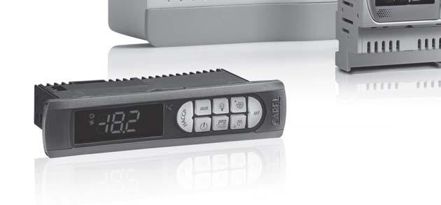
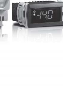
7 1. INTRODUCTION The ir33 platform for refrigeration is a complete range of products made up of integrated electronic microprocessor controllers with LED display, designed especially for the control of stand-alone refrigeration units: These controllers are especially suitable in applications that require high load switching power, a considerable number of outputs, functions and control with direct access from the keypad, high front panel IP and, at the same time, a compact shape that signifi cantly reduces the overall dimensions. The irr33 range is easy to install and ensures optimisation of production times for the manufacturer in mass production. Numerous models are available, providing the best solution for each application at the most competitive price. 1.1 Main features Power supply Models are available with power supply in the following versions: 12Vac, 12 to 24 Vac/dc (switching), 230Vac or 115 to 230 Vac (switching). All the models, furthermore, feature a low power mode to increase immunity to voltage drops. When the voltage inside the instrument falls below a certain threshold, the unit switches off the display so as to reduce power consumption, while still continuing to operate normally: the main relays remain energised and, as soon as the voltage returns to the normal level, the display comes on again. LED display The controller is fitted with a very powerful and aesthetically pleasant display, with 3 digits and decimal point, minus sign and icons to simplify the reading of the values and the operating status. Alarm buzzer All models are fitted with a buzzer to signal the alarms Keypad Keypad with 4 or 8 buttons, depending on the product, with clear indications and direct functions. Remote control To simplify the setting and display of the parameters, depending on the model, the instrument can be fi tted with an infrared receiver to allow the use of the new compact remote control: this device can be used on a series of ir33 controllers in the same room, without problems of interference. In fact, each controller is identifi ed by a different access code. Duty setting This function ensures the operation of the compressor even when the control probe (room probe) is faulty. If the probe is disconnected or short-circuited, the compressor is activated at set intervals, with a running time (in minutes) equal to the value assigned to the duty setting parameter (parameter C4), and a fi xed OFF time of 15 minutes. Smart defrost All ir33 series controllers can, as standard, manage the defrost functions in new modes with much more effi cient algorithms for optimising the times (see the paragraph on smart defrosts). Multifunction input All the instruments have two digital inputs that can be used in different modes, depending on the value set for the digital input confi guration parameters (parameters A4 and A5 for ir33, ir33power, powercompact small, + parameter A9 for ir33din, powercompact, MasterCella). These inputs can be used to enable/disable the defrost, to manage serious alarms that require the immediate shut-down of the unit (e.g. high pressure) or delayed shut-down of the unit (e.g. low pressure), or alternatively can be confi gured to read NTC probes, with parameters /3 and /4 for ir33, ir33power, powercompact small, + parameter /A5 for ir33din, powercompact, MasterCella. Multifunction output According to the model, the ir33 family can be provided with an additional multi-function output for remote control of the alarm signal for controlling additional units with ON/OFF activation. Real time clock The wide range also includes models fi tted with built-in real time clock. Pump down This function ensures the compressor is stopped only when the evaporator is discharged (see the paragraph Pump down and low pressure ). Condenser One of the new characteristics offered by these controllers is the possibility to manage, via an NTC probe input, the condensing temperature for both the alarms and control functions, using the auxiliary output confi gured by parameters H1 and H5. Double evaporator Two independent evaporators can be managed, connected to the same circuit. The end of defrost temperatures are independent and can be set by parameters dt1/dt2. Fig. 1.a - ir33, ir33 power Fig. 1.b - ir33din Fig. 1.c - powercompact - powercompact small Fig. 1.d - MasterCella 7
8 HACCP This function, increasingly required in the refrigeration market, is included as standard on all models with clock. This allows the monitoring of critical points by measuring and recording the temperatures in the event of high temperature alarms or power failures. Up to 3 high temperature alarms and 3 alarms corresponding to power failures can be saved. Light management The ir33 platform has been enhanced by the introduction of the function for managing the light when the door opens, set by parameter. Keypad protection The keypad and the remote control can be disabled to avoid tampering by unauthorised persons, above all in the event when the controller is installed in an area open to the public. Continuous cycle The continuous cycle function ensures the operation of the compressor for the time set by the corresponding parameter. This function is useful when a rapid reduction in the temperature is required. Serial connection The entire range has an RS485 serial port for network connection to supervisor or telemaintenance systems using a shielded twisted pair cable. Index of protection The gasket inside the front panel and the material used to make the keypad guarantee IP65 protection for the controller on the front panel. Installation The controllers are mounted using the screws at the front, or alternatively using two quick-fi t side brackets, with compact dimensions, made from plastic. In-circuit testing The ir33 platform controllers are made using the most advanced SMD technology. All the controllers undergo IN-CIRCUIT TESTING to check electrical operation of all components. NTC probe The controllers can manage two types of NTC probes (see parameter /P ): standard version 50T90 C (NTC0*HP*) or alternatively the model for high temperatures, up to 150 C (enhanced NTC 40T150 C). Watch dog This feature prevents the microprocessor from losing control over the unit even in the presence of considerable electromagnetic disturbance. In the event of abnormal operation, the watchdog function re-establishes the initial operating status. Not all the competitors fi t their products with this safety feature. Electromagnetic compatibility The ir33 platform is compliant with EU standards on electromagnetic compatibility. The quality and the safety of the ir33 controllers are ensured by the CAREL ISO 9001 certifi ed design and production system and by the CE mark on the product. Network functions The controllers feature management of multiplexed defrosts, remote alarm signals and the downloading of the parameters via the local network. Parameter selection Selection of the parameters on the display simplifi ed by the use of icons or with the standard Carel procedure. Confi guration of the digital inputs The digital inputs can be confi gured and used as NTC probe inputs, by simply setting a parameter. Connectors Models fi tted with spade connectors or fi xed screw terminals. Options programming key; RS485 serial interface can be added at any time; optional repeater display for models with switching power supply. For further information, see the chapter on Accessories. Number of relays Number of relays Compressor Light ir33 from 1 to 4 8A and 16 A ir33power from 1 to 4 2Hp ir33din from 1 to 5 16 A and 2Hp powercompact from 2 to 5 8A, 16 A and 2Hp powercompact small from 2 to 4 2Hp mastercella from 3 to 5 30 A 70A (2Hp) 8
9 2. USER INTERFACE 2.1 Display MasterCella Fig. 2.a ir33, ir33 DIN, ir33 power, powercompact, powercompact small ICON FUNCTION DESCRIPTION Start up ON OFF BLINK COMPRESSOR ON when the compressor starts. Flashes when the activation Compressor on Compressor off awaiting activation of the compressor is delayed by safety times. FAN DEFROST AUX ALARM ON when the fan starts.flashes when the activation of the fan is prevented due to external disabling or procedures in progress. ON when the defrost is activated. Flashes when the activation of the defrost is prevented due to external disabling or procedures in progress. Flashes if the anti-sweat heater function is active, ON when the auxiliary output (1 and/or 2) selected as AUX (or LIGHT in fi rmware version 3.6) is activated. ON following pre-activation of the delayed external digital input alarm. Flashes in the event of alarms during normal operation (e.g. high/low temperature) or in the event of alarms from an immediate or delayed external digital input. Fan on Fan off awaiting activation Defrost in progress Defrost not in progress awaiting activation AUX auxiliary output AUX auxiliary output active(version 3.6 light auxiliary not active output active) Delayed external alarm (before the time A7 elapses) No alarm present Anti-sweat heater function active Alarms in norm. operation (e.g. High/low temperature) or immediate or delayed alarm from external digital input CLOCK ON if at least one timed defrost has been set.at start-up, comes ON for a few seconds to indicate that the Real Time Clock is fi tted. If at least 1 timed defrost event has been set No timed defrost event set Alarm clock ON if realtime clock present LIGHT SERVICE Flashes if the anti-sweat heater function is active, ON when the auxiliary output (1 and/or 2) selected as LIGHT is activated (in fi rmware version 3.6 it does not fl ash in anti-sweat heater mode and comes on when the dead band output is active). Flashes in the event of malfunctions, for example E2PROM errors or probe faults. Light auxiliary output on(version 3.6 dead band auxiliary output active) Light auxiliary output off No malfunction Anti-sweat heater function active(version 3.6 does not fl ash in anti-sweat heater mode) Malfunction (e.g. E2PROM error or probe fault). Contact service DISPLAY Shows temperature in range -50 to +150 C.The temperature is displayed with resolution to the tenths between 19.9 and C (59.9 in fi rmware revision 3.4). The display of the tenths can be disabled by setting a parameter. HACCP CONTINUOUS CYCLE ON if the HACCP function is enabled.flashes when there are new HACCP alarms stored (HA and/or HF alarm shown on the display). ON when the CONTINUOUS CYCLE function is activated. Flashes if the activation of the function is prevented due to external disabling or procedures in progress (E.g.: minimum compressor OFF time). HACCP function enabled CONTINUOUS CYCLE operation activated HACCP function not enabled CONTINUOUS CYCLE function not activated HACCP alarm saved (HA and/or HF) CONTINUOUS CYCLE operation requested Tab. 2.a 9
10 2.2 ir33, ir33 power and ir33din keypad ir33, ir33 power Fig. 2.b ir33 DIN 7 Icon Start up Automatic address assignment request pressing the button alone pressing together with other buttons PRG/MUTE aux UP/AUX def DOWN/DEF SET Set If pressed for more than 5 seconds, accesses the menu for setting the type F parameters (frequent).mutes the audible alarm (buzzer) and deactivates the alarm relay If pressed for more than 1 s, activates deactivates the auxiliary output. If pressed for more than 5 seconds activates a manual defrost If pressed for more than 1 second, displays and/or sets the set point. PRG+SET: if pressed together for more than 5 seconds, accesses the menu for setting the type C parameters (confi guration) or downloading the parameters.prg+up/ AUX: if pressed for more than 5s, resets any alarms with manual reset UP/AUX+DOWN/DEF: if pressed together for more than 5 seconds, activates/deactivates continuous cycle operation. UP/AUX +SET: if pressed together for more than 5 seconds, starts the report printing procedure (if the controller is connected to the printer interface).up/aux +PRG/MUTE: if pressed together for more than 5 seconds, resets any active alarms with manual reset. DOWN/DEF +UP/AUX: if pressed together for more than 5 seconds activates/deactivates continuous cycle operation. DOWN/DEF +SET: if pressed together for more than 5 seconds, displays a sub-menu used to access the parameters relating to the HACCP alarms ( HA, HAn, HF, HFn ). SET+PRG/MUTE: if pressed together for more than 5 seconds accesses the menu for setting the type C parameters (configuration) or downloading the parameters.set+down/def: if pressed together for more than 5 seconds, displays a sub-menu used to access the parameters relating to the HACCP alarms ( HA, HAn, HF, HFn ).SET+UP/AUX: if pressed together for more than 5 seconds, starts the report printing procedure (if the controller is connected to the printer interface). If pressed for more than 5 seconds at start-up, activates the RESET default parameters procedure If pressed for more than 1 second, starts the automatic address assignment procedure Tab. 2.b Procedure for displaying and deleting the HACCP alarms 1. Press +SET for more than one second; 2. the display will show the name of the fi rst of the parameters of the HA and HF alarms; 3. use the + buttons to display the codes relating to the HA and HF alarms; 4. when having reached the desired parameter press SET to display the value; 5. if the selected parameter is HA or HF, us +, to scroll the year, month, day, hour, minutes and duration of the last HA or HF alarm activated. e.g.: y03 M07 d22 h23 m57 t99 start again The sequence indicates that the last HA or HF alarm was activated on 22 July 2003 at 23:57 and lasted 99 hours. Press SET again to return to the list of the parameters relating to the HA and HF alarms. The following operations are possible from inside the menu: a. delete the HACCP alarm by pressing +SET for more than 5 seconds (the message res indicates that the alarm has been deleted, the HACCP LED stops fl ashing, the HA and/or HF signal is also reset, and the monitoring of HA is reinitialised); b. delete the HACCP alarms and the alarms saved (HAn, HA, HA1, HA2, HFn, HF, HF1, HF2) by pressing, SET and for more than 5 seconds (the message res indicates that the alarms have been deleted, the HACCP LED stops fl ashing, the HA and/or HF signal is reset, the HAn, HA, HA1, HA2, HFn, HF, HF1, HF2 alarms saved are reset and the monitoring of HA is reinitialised) c. can be resumed at any time by pressing the button for 3 seconds or waiting for the expiry of the session due to timeout (60 seconds) without pressing any button. 10
11 2.3 powercompact, powercompact small and MasterCella keypad MasterCella Fig. 2.c powercompact, powercompact small Icon Start up Automatic address assignment request pressing the button alone pressing together with other buttons Enters the menu to display and delete of the HACCP alarms HACCP ON/OFF PRG/MUTE UP/CC LUCE AUX If pressed for more than 5 seconds, switches the unit on/off If pressed for more than 5 seconds accesses the menu for setting the type F parameters (frequent)in the event of alarms: mutes the audible alarm (buzzer) and deactivates the alarm relay If pressed for more than 5 seconds activates/deactivates the continuous cycle If pressed for more than 1 second, activates/deactivates auxiliary output 2 If pressed for more than 1 second, activates/deactivates auxiliary output 1 If pressed for more than 5 seconds activates/deactivates a manual defrost. PRG/MUTE+SET: if pressed for more than 5 seconds accesses the menu for setting the type C parameters (configuration) or downloading the parameters.prg/mute+up/cc: if pressed for more than 5 seconds, resets any alarms with manual reset UP/CC+SET: if pressed together for more than 5 seconds starts the report printing procedure (if the interface printer is connected to the controller)up/cc+prg/mute: if pressed together for more than 5 seconds, resets the any alarms with manual reset If pressed for more than 5 seconds at start-up, activates the procedure for restoring the default parameters If pressed for more than 1 second, starts the automatic address assignment procedure DOWN/DEF SET If pressed for more than 1 second, displays and/or sets the set point. SET+PRG/MUTE: if pressed for more than 5 seconds accesses the menu for setting the type C parameters (configuration) or downloading the parameters.set+up/cc: if pressed together for more than 5 seconds starts the report printing procedure (if the interface printer is connected to the controller). Tab. 2.c Procedure for displaying and deleting the HACCP alarms 1. Press the HACCP button (powercompact, powercompact small and MasterCella) or alternatively +SET for ir33, ir33power and ir33din for more than one second; the display will show the name of the first of the parameters of the HA and HF alarms. 2. use the and buttons to display the codes relating to the HA and HF alarms; 3. when having reached the desired parameter press SET to display the value; 4. if the selected parameter is HA or HF, use and, to scroll the year, month, day, hour, minutes and duration of the last HA or HF alarm activated. Example: y03 M07 down d22 h23 m57 t99 start again The sequence indicates that the last HA or HF alarm was activated on 22 July 2003 at 23:57 and lasted 99 hours. 5. Press SET again to return to the list of the parameters relating to the HA and HF alarms. The following operations are possible from inside the menu: delete the HACCP alarm by pressing the HACCP button (for powercompact and small, MasterCella), or +SET (ir33, ir33power and ir33din) for more than 1 second. The message res indicates that the alarm has been deleted (the HACCP LED stops fl ashing, the HA and/or HF signal is also reset, and the monitoring of HA is reinitialised); delete the HACCP alarms and the alarms saved (HAn, HA, HA1, HA2, HFn, HF, HF1, HF2) by pressing the HACCP button for more than 5 seconds (the message res indicates that the alarms have been deleted, the HACCP LED stops fl ashing, the HA and/or HF signal is reset, the HAn, HA, HA1, HA2, HFn, HF, HF1, HF2 alarms saved are reset and the monitoring of HA is reinitialised). 6. can be resumed at any time by pressing the prg button for 3 seconds or waiting for the expiry of the session due to timeout (60 seconds) without pressing any button. 11
12 3. INSTALLATION To install the controller, proceed as follows, with reference to the connection diagrams shown in the manual on electrical specifi cations and connections: 1. connect the probes and power supply: the probes can be installed up to a maximum distance of 10 m from the controller, using shielded cables with a minimum cross-section of 1mm². To improve the immunity to disturbance, use probes with shielded cables (connect only one end of the shield to the earth on the electrical panel). 2. Program the instrument: for more details, see the chapter Programming the instruments. 3. Connect the actuators: the actuators should only be connected after having programmed the controller. In this connection, carefully check the maximum capacities of the relays, indicated in the technical specifi cations. 4. Serial network connection: all ir33 models are fi tted with a serial connector for connection to the supervisory network via the serial interface code IROPZ Take care when earthing the system, in particular the secondary winding of the transformers that supply the instruments must not be earthed. If connection to a transformer with earthed secondary winding is required, an insulating transformer must be installed in between. A series of instruments can be connected to the same insulating transformer, nevertheless you are recommended to use a separate insulating transformer for each instrument. Warnings: Avoid installing the instrument in environments with the following characteristics: relative humidity over 90% non-condensing; heavy vibrations or knocks; exposure to continuous jets of water; exposure to aggressive and polluting atmospheric agents (e.g.: sulphur and ammonia gases, saline mist, smoke) which may cause corrosion and/or oxidation; high magnetic and/or radio frequency interference (e.g. near transmitting antennas); exposure to direct sunlight and atmospheric agents in general. The following warnings must be observed when connecting the controllers: Incorrect connection of the power supply may seriously damage the system; use cable ends that are suitable for the terminals. Loosen every screw and fi t the cable end, next tighten the screws and gently pull the cables to check their tightness. When tightening the screws, do not use automatic screwdrivers, or adjust the screws to a tightening torque less than 50 Ncm; separate as much as possible (by at least 3 cm) the probe signal and digital input cables from inductive loads and power cables, to avoid any electromagnetic disturbance. Never lay power cables and probe cables in the same cable conduits (including those for the electrical panels). Do not install the probe cables in the immediate vicinity of power devices (contactors, circuit breakers or the like). Reduce the length of the sensor cables as much as possible, and avoid spirals around power devices; only use IP67 guaranteed probes as end defrost probes; place the probes with the vertical bulb upwards, so as to facilitate drainage of any condensate. Remember that the thermistor temperature probes (NTC) have no polarity, so the order of connection of the ends is not important. Cleaning the instrument When cleaning the instrument do not use ethanol, hydrocarbons (petrol), ammonia and by-products. Use neutral detergents and water. 12
13 4. PROGRAMMING THE INSTRUMENTS The operating parameters can be modifi ed using the front keypad, and are divided into two families: frequent use parameters (type F ) and confi guration parameters (type C ). Access to the confi guration parameters is protected by a password that prevents unwanted modifi cations or access by unauthorised persons. How to access type F parameters (frequent use): press PRG for more than 5 seconds (if an alarm is active, the buzzer is muted fi rst of all), the display shows the code of the fi rst modifi able type F parameter. How to access type C parameters (confi guration): 1. Press prg and SET together for more than 5 seconds; the display will show the number 00, representing the password prompt; 2. press or until displaying the number 22 (the code of the password allows access to the parameters); 3. confi rm by pressing SET; the display will show the code of the fi rst modifi able type C parameter. 4.1 Modifying the parameters After having displayed the parameter, either type C or type F, proceed as follows: 1. press or suntil reaching the parameter to be modifi ed. When scrolling, an icon appears on the display representing the category the parameter belongs to. Alternatively, press prg to display a menu that is used to quickly access the family of parameters to be modifi ed; 2. scroll the menu with the and buttons; the display shows the codes of the various categories of parameters (see the Summary of operating parameters ), accompanied by the display of the corresponding icon (if present); 3. when having reached the desired category, press SET to move directly to the fi rst parameter in the category (if there are no visible parameters in the selected category, pressing SET will have no effect); 4. at this stage, continue to scroll the parameters, or return to the categories menu by pressing prg; 5. press SET to display the value associated with the parameter; 6. increase or decrease the value using the or button respectively; 7. press SET to temporarily save the new value and return to the display of the parameter code. Repeat the operations from point 1 or point 2; 8. if the parameter has sub-parameters, press SET to display the fi rst sub-parameter; 9. press or to display all the sub-parameters; 10. press SET to display the associated value; 11. increase or decrease the value using the or button respectively; 12. press SET to temporarily save the new value and return to the display of the sub-parameter code; 13. press prg to return to the display of the parent parameter. 4.2 Storing the new values assigned to the parameters To defi nitively store the new values of the modifi ed parameters, press prg for more than 5 seconds, thus exiting the parameter setting procedure. All the modifi cations made to the parameters, temporarily stored in the RAM, can be cancelled and normal operation resumed by not pressing any button for 60 seconds, thus allowing the parameter setting session to expire due to timeout. Important: if the programming session ends by timeout, the clock parameters will not be reset, as these parameters are saved immediately when entered. If the instrument is switched off before pressing prg, all the modifi cations made to the parameters and temporarily saved will be lost. 4.3 Classification of the parameters The parameters, as well as being divided by TYPE, are also grouped into logical CATEGORIES identifi ed by the initial letters or symbols. The following table lists the categories and the corresponding letters. Parameters Category Text Icon / Temperature probe management parameters Pro r Temperature control parameters CtL c Compressor safety time and activation parameters CMP d Defrost management parameters def A Alarm management parameters ALM F Fan management parameters Fan H confi guration General confi guration parameters (addresses, enabling, etc. ) CnF H haccp HACCP parameters HcP rtc RTC parameters rtc Tab. 4.a 13
14 4.4 Downloading the parameters via the network 1. Press the prg and SET buttons together for more than 5 seconds; the display will show the number 00 ; 2. press the or button to scroll the numbers until displaying 66 (download activation password), then confi rm by pressing SET; 3. the display will show the message dnl, indicating that the download is in progress; 4. at the end of the procedure, the message dnl is cancelled and, in the event of errors, one of the messages d1 to d6 is displayed to indicate which unit the error occurred on. 4.5 Setting the set point 1. Press SET for more than 1 second to display the set point; 2. increase or decrease the set point using the or buttons respectively, until reaching the desired value; 3. press SET again to confi rm the new value. 4.6 Alarms with manual reset The alarms with manual reset can be reset by pressing prg and ptogether for more than 5 seconds, if the causes are no longer present. 4.7 Procedure for setting the default parameter values To set the default parameter values, if Hdn = 0, proceed as follows: 1. switch the instrument off; 2. switch the instrument on again, holding the prg and SET buttons until the message _std_ is shown on the display. Note: the default values are set only for the visible parameters (e.g. C or F), according to the model; see the table of Operating parameters. If Hdn <> 0, a number of sets of customised default parameters are available. Proceed as follows: 1. switch the instrument off; 2. switch the instrument on again, holding prg and SET until the value 0 is displayed; 3. use and to select the desired set of default parameters. The sets between 0 and Hdn can be chosen; 4. pressing the button shows the message Std on the display. Set Customisable Note 0 NO The levels of visibility are not modifi ed. Used to set the values of the visible parameters only. 1, 2, 3 4, 5, 6 YES Sets the levels of visibility and the values of all the operating parameters. The unit parameters are not set. Tab. 4.b Note: The set of customisable default parameters can only be used on the controller if there is suitable hardware (expanded EEPROM memory); if when loading a set of customised default parameters there is an EF EEPROM error (memory error on the controller), the previous parameters can be restored by switching the instrument off and on again; if there is an EF EEPROM error, to maintain the loaded parameters, enter parameter confi guration mode, check the values then save them to the EEPROM using the special procedure. At then end of the operation, the EEPROM error signal will be cancelled; if there is a recurring EF EEPROM error when loading a set of customised default parameters, the EEPROM on the instrument should be corrected using the hardware programming key; after loading a set of customised default parameter, the controller automatically updates the memory, saving both the levels of visibility and the values of the parameters; Hdn must have the same value in all the sets of customised default parameters; for greater protection, parameter Hdn must be set to not visible. 4.8 Semi-automatic serial address assignment procedure The automatic setting of the serial address is a special procedure that, by using an application installed on a PC connected to the CAREL network (included in the PlantVisor supervision and monitoring software), sets and manages the addresses of all the instruments that include this feature in a simple way. Using the remote application, start the Network defi nition procedure; the application begins to send a special message ( <!ADR> ) across the network, containing the network address. Then: 1. press the prg button on the keypad of the instrument connected to the network, the instrument recognises the message sent by the remote application, automatically setting the address to the required value and sending a confi rmation message to the application, containing the unit code and fi rmware revision (message V ). When the message sent by the remote application is recognised, the instrument displays the message Add for 1 second, followed by the value of the assigned serial address; 2. the application, on receiving the confi rmation message from the units connected to the network, saves the information received in its database, increases the serial address and resumes sending the message <!ADR>. The procedure can be repeated starting from point 2 on another unit connected to the network, until all network addresses are defi ned. Note: when the operation for assigning an address to an instrument has fi nished, for reasons of safety, the operation is inhibited for 1 minute on that instrument. Consequently, a different address cannot be re-assigned to the instrument during that time. 14
15 5.1 Parameter copying key 5. ACCESSORIES Programming keys PSOPZKEY00/A0 The programming keys PSOPZKEY00 (Figure 5.a) and PSOPZKEYA0 (Figure 5.b) are used to copy the complete set of parameters relating to the CAREL ir33 controller parameters. The keys must be connected to the connector (4 pin AMP) fi tted on the compatible controllers, and work even without switching the controller on. Programming keys IROPZKEY00/A0 The programming keys IROPZKEY00/A0, unlike the PSOPZKEY00/A0, with the use of the confi guration kit PSOPZPRG00, can set up to seven different confi gurations of parameters inside the instrument. The keys must be connected to the connector (4 pin AMP) fi tted on the controllers. The keys IROPZKEY00/ A0 can only be used with the controllers based on the IR33 platform. All operations must be performed with the instrument off, unless otherwise indicated on the instruction sheet for the specifi c instrument. Important: PJOPZKEY00 to be used ONLY for PJ controllers; - PSOPZKEY** to be used ONLY for powercompact/ir33, Mastercella, power-split, MGE controllers and I/O modules. UPLOAD Fig. 5.a Fig. 5.b Three functions are available, and are selected by using the two supplied dipswitches; these can be accessed by removing the battery cover: load the parameters for a controller onto the key (UPLOAD - Fig. 5.c); copy from the key to a controller (DOWNLOAD - Fig. 5.d); extended copy from the key to a controller (EXTENDED DOWNLOAD - Fig. 5.e). Warning: the parameters can only be copied between instruments with the same code. The UPLOAD operation can, however, always be performed. DOWNLOAD Fig. 5.c Copying and downloading the parameters The following operations are used for the UPLOAD and/or DOWNLOAD or EXTENDED DOWNLOAD functions, simply by changing the settings of the dipswitches to change the function: 1. open the rear cover on the key and position the 2 dipswitches according to the desired operation; 2. close the rear cover on the key and insert the key in the connector on the controller; 3. press the button and check the LED: red for a few seconds, then green, indicates that the operation was completed correctly. Other signals or the fl ashing of the LED indicates that problems have occurred: refer to the table below; 4. at the end of the operation, release the button, after a few seconds the LED goes OFF; 5. remove the key from the controller. EXTENDED DOWNLOAD Fig. 5.d Fig. 5.e LED signal Cause Meaning and solution Red LED fl ashing Batteries discharged at start copy The batteries are discharged, the copy operation cannot be performed. Replace the batteries. Green LED fl ashing Red/green LED fl ashing (orange signal) Batteries discharged during copy or at end of copy Instrument not compatible During the copy operation or at the end of the operation the battery level is low. Replace the batteries and repeat the operation. The parameter set-up cannot be copied as the connected controller model is not compatible. This error only occurs for the DOWNLOAD function; check the code of the controller and run the copy only for compatible codes. Red and green LEDs ON Error in data being copied Error in the data being copied. The instrument s EEPROM is corrupted, and therefore the key cannot be copied. Red LED on steady Data transfer error The copy operation was not completed due to a serious error when transferring or copying the data. Repeat the operation, if the problem persists check the key connections. LEDs OFF Batteries disconnected Check the batteries. Notes: Tab. 5.a 1. at the start and the end of the UPLOAD and DOWNLOAD operations (normal or extended), the buzzer on the instrument will emit an audible signal; 2 the DOWNLOAD operation (normal or extended) is possible even if the operating parameters and controller are incorrect. If there is an error in the unit parameters, these will be recovered by the key. Be careful when recovering the unit parameters from a key, as these determine the low-level operation of the controller (unit model, type of interface, assignment of logical relay to physical relay, brightness of the display, level of modulation of the relay control signal ). The unit parameters from the original model must therefore be restored to ensure the correct operation of the controller. 15


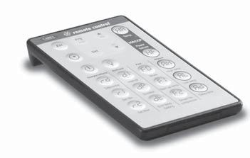
16 Fig. 5.f Fig. 5.g 5.2 Remote control The compact remote control with 22 buttons, allows direct access to the following parameters (Fig. 5.f): temperature; defrost; fans; alarms; HACCP. The following functions can also be controlled: start defrost; AUX; light; ON/OFF; mute. The standard remote control features the four buttons, PRG/mute, SET, UP and DOWN, which access almost all the functions provided by the instrument keypad. The buttons can be divided into three groups, based on their functions: Buttons for enabling and disabling the use of the remote control (Figure 5.g); Buttons for remote simulation of the instrument keypad (Figure 5.h); Buttons for direct display/modifi cation of the most commonly used parameters (Figure 5.i). Activating and deactivating the use of the remote control Button Immediate function Delayed function START used to enable the remote control; each instrument displays its own enabling code EXIT ends operation using the remote control, cancelling all changes made to the parameters PRG used to display the confi guration parameters pressing and holding for 5s ends use of the remote control, saving the modifi ed parameters. NUMBERS used to select the instrument, by entering the enabling code displayed. Tab. 5.b By pressing the START button, each instrument displays its own remote control enabling code (H3). The numeric keypad is used to enter the enabling code of the instrument in question. At the end of this operation, only the instrument with the selected enabling code will be programmed from the remote control, all the others will resume normal operation. Assigning different enabling codes to the instruments, allows, in this phase, only the desired instrument to be programmed using the remote control, without the risk of interference. The instrument enabled for programming from the remote control will display the reading and the message rct. This status is called Level 0. When having entered programming mode, pressing prg for 5 seconds exits the programming of the remote control, saving the modifi cations; vice-versa, press EXIT to exit the programming of the remote control, without saving the modifi cations Fig. 5.h Remote simulation of the instrument keypad The highlighted part is used to simulate the instrument keypad from the remote control. In Level 0 (display the reading and message rct), the following functions are active: Button Immediate function def start and stop defrosting aux activation and deactivation of auxiliary relay 1 light activation and deactivation of auxiliary relay 2 ON/OFF instrument ON/OFF PRG/mute mute the buzzer, if ON, and deactivate the alarm relay Tab. 5.c In this level, the set and PRG/mute buttons are also active, used to activate the set point (Level 1) and the confi guration parameters (Level 2). Fig. 5.i Button Immediate function Delayed function PRG/mute modify the confi guration parameters pressing and holding for 5s saves the modifi ed parameters set modify the set point Tab. 5.d In Levels 1 and Level 2, the PRG/mute, SET, UP and DOWN buttons repeat the corresponding functions on the instrument keypad. In this way, all the instrument parameters can be displayed and modifi ed, even those without shortcut buttons. Directly display/modify the most commonly used parameters: Some parameters, relating to: Temperature, Defrost, Alarms, Fans, HACCP are directly accessible using specifi c buttons. 16
. For further details, refer to the corresponding instruction sheet. Fig. 5.l 5.")


 mean they can be used in all types of applications. Code: TRA12VDE00: Transformer, 3VA 240/12VAC VDE - 153/M Fig. 5.m 5.")


17 5.3 RS485 serial interface The RS485 serial card option (IROPZ48500), shown in Figure 5.l, allows the ir33 instrument to be connected to the RS485 serial network for supervision. In addition, the serial interface option IROPZ485S0 is available, with automatic recognition of the polarity (+ and -). For further details, refer to the corresponding instruction sheet. Fig. 5.l 5.4 Programming kit This accessory interfaces the IROPZKEY00 programming key with any PC; this useful tool can be used to program the key using the standard instrument parameters, and save the different confi gurations to fi les that can be recalled during fi nal programming. For the new generation instruments, such as powercompact and ir33, the user can change the password, hide the parameters, change the level of visibility (with password protection or direct access) and, most importantly, assign the output relays according to the confi guration of the utilities. 5.5 Transformers (ir33, power, DIN) The transformers are used to convert mains voltage to the power supply voltage specifi ed for the ir33 and ir33din series controllers. Their compactness and sound design (winding immersed in plastic) mean they can be used in all types of applications. Code: TRA12VDE00: Transformer, 3VA 240/12VAC VDE - 153/M Fig. 5.m 5.6 RS485 serial board (DIN) The IROPZSER30 board is used to connect the ir33din via the RS485 network serial to the PlantVisor supervisory system (using the removable terminal supplied), as well as direct connection of the instrument to the repeater display using a PSTCON**B00 cable. Fig. 5.n Fig. 5.o 5.7 RS485 serial board (MasterCella) The IROPZSEM10/30 boards are used to connect the mastercella via the RS485 network serial to the PlantVisor supervisory system. The IROPZSEM30 board also allows the repeater display to be connected directly to mastercella using a PSTCON**B00 cable. Codes: IROPZSEM10: RS485 serial board; IROPZSEM30: RS485 serial board + repeater display connection. Fig. 5.p 5.8 Door interlock (MasterCella) Mastercella can be installed with a door interlock disconnecting switch, rated to 32 A, for the complete on/off management of all the units; this device allows the system to be locked in the Off position so that service operations can be performed in complete safety. Codes: CEL, 32 A disconnecting switch; CEL, shaft H=85mm; CEL, switch with yellow/red indicator. Fig. 5.q 17


, shown in the fi gure below, allows the ir33 to interface with a repeater display (IR00R*0000) to show the")
18 Fig. 5.r Fig. 5.s Fig. 5.t 5.9 Terminals (MasterCella) This accessory is used to group together the neutral, live and earth connections on a single board installed inside the mastercella. There are two models available: with 3 and 5 rows of terminals. In particular, the second accessory allows direct access with the cables from the loads (live, neutral and earth) to this board alone, thus avoiding having to make the connections during installation to the support terminal block on the mastercella. Codes: MDOPZCA000, 3 sets of connections; MDOPZCB000, 5 sets of connections Repeater display interface option The repeater display interface option (IROPZDSP00), shown in the fi gure below, allows the ir33 to interface with a repeater display (IR00R*0000) to show the temperature measured by the third probe. For further details on the connection, refer to the specifi c instruction sheet IR00R*0000 display terminal This can be connected in parallel with the interface for setting the parameters. It displays the temperature read by the third probe installed in the hottest point of the cabinet, as required by the EN standard. Codes: IR00RG0000 = ir33 green repeater display; IR00RG0000 = ir33 red repeater display 5.12 PST00VR100 display terminal (powercompact) Same as for the IR00R*0000. Fig. 5.u ir33 powercompact powercompact small IROPZDSP00 PSTCON0**B0 IR00R* Optional interface-repeater display connection cable The connection cables between the interface and the repeater display have the following codes: for ir33, ir33 power, ir33din, powercompact and powercompact small. PSTCON01B0 = 1.5 m PSTCON03B0 = 3 m PSTCON05B0 = 5 m for MasterCella only: PSTCON0300: 3 m PSTCON1000: 10 m ir33 DIN IR00R*0000 PSTCON0**B0 IROPZSER30 IROPZSEM30 MasterCella PSTCON0**00 IR00R*0000 Fig. 5.v 18
19 6. DESCRIPTION OF THE FUNCTIONS 6.1 Models Below is a list of the functions relating to the various models of controller. Function M (*) S Y F C H (**) A (***) D (***) temperature display display second probe with external contact temperature alarm monitoring compressor control defrost with compressor stop defrost with heater or hot gas continuous cycle duty setting evaporator fans auxiliary output 1 auxiliary output 2 Tab. 6.a The controllers can be fi tted with a maximum of two auxiliary relays. The associated functions are: alarm output, normally open or closed; auxiliary output; light output; second evaporator output; control output for pump down valve; control output for condenser fans; second delayed compressor output, auxiliary output, with deactivation when OFF; light output, with deactivation when OFF; no function associated with the output; reverse output in control with dead band; second compressor step output; second compressor step output with rotation. (*) = ir33 only (**) = powercompact and ir33 DIN only (***) = mastercella only The controllers can be fi tted with a maximum of three digital inputs (or three probe inputs). The associated functions are: immediate alarm; delayed alarm; select probe displayed (model M); enable defrost; start defrost; door switch with compressor and fan shutdown and light management; remote ON/OFF; curtain switch with set point variation and light management; low pressure alarm; door switch with fan shutdown and light management; direct/reverse selection; light sensor and light management; door switch with compressor and fans off, without light management; door switch with fans off, without light management. The controllers can be fi tted with a maximum of fi ve probes (three of which as alternatives to the digital inputs). The associated functions are: ambient probe (used to calculate the virtual control probe); product probe (if necessary, used to calculate the virtual control probe); defrost probe (main or secondary evaporator, end defrost on 3 evaporator temperature probes); condenser probe (used, if necessary, for condenser fan control). Other functions that enhance the range of the refrigeration controllers include: real time clock, for management of real time defrosts; real time clock for HACCP alarms management; real time clock for the activation/deactivation of the AUX and LIGHT outputs; real time clock for the automatic variation of the set point 6.2 Testing the display and keypad on start-up When the controller is switched on, a special procedure tests the display and the keypad: Phase Display Keypad Note First Display completely OFF for 2 seconds Press prg for 2 seconds to set the default values Second Display completely ON for 2 No effect seconds Third Three segments ( --- ) on Pressing each button lights up a In this phase, appears specifi c segment to indicate the presence of the RTC Fourth Tab. 6.b 19
20 6.3 Switching the controller ON and OFF The unit can be switched ON/OFF from a number of sources; supervisor and digital input. In this operating mode, the display will be show the temperature selected for parameter /ti, alternating with the OFF message. The digital input can be used to switch the controller on/off, setting parameter A4/A5 to 6. Switching on/off from digital input has priority over the same function from the supervisor. Origin Priority Note Digital input Priority 1 Disable On/Off from keypad and supervisor Keypad Priority 2 Supervisor Priority 3 Tab. 6.c OFF status: Important: if there is more than one digital input selected as the On/Off function (A4 and A5 = 6), the ON status will be activated when all the digital inputs are closed. If event one contact is open, the unit is switched OFF. Function Enabled Disabled compressor control (pump down valve OFF and shut) AUX control (H1= 11) with dead band second compressor step control with and without rotation (H1= 12, 13) defrost (cyclical and manual) fan control fan control at low relative humidity (if enabled) continuous cycle condenser fan control (if enabled) low temperature alarm (LO, alarm reset, and monitoring initialised) high temperature alarm (HI, alarm reset, and monitoring initialised) immediate alarm from external contact (IA, alarm reset and monitoring initialised) delayed alarm from external contact (da, alarm reset and monitoring initialised) defrost ended due to timeout alarm (Ed1 and Ed2, alarm reset) pump down ended due to maximum time alarm (Pd, alarm reset) low pressure from external contact alarm (LP, alarm reset and monitoring initialised) autostart alarm in pump down (AtS, alarm reset and not displayed) pre-alarm: high condenser temperature (cht, alarm reset, and monitoring initialised) high condenser temperature alarm (Cht, alarm reset, and monitoring initialised) door open for too long alarm (dor, alarm reset) antifreeze alarm (AFr, alarm reset) HA HACCP alarm (alarm reset, and monitoring initialised) HF HACCP alarm (alarm reset, and monitoring initialised) buzzer (OFF) and alarm relay (non-alarm status) HACCP control defrost according to programmed time bands defrost according to compressor running time (if enabled) defrost from digital input (if enabled) defrost from keypad and supervisor defrost started from digital input (if enabled) direct/reverse from digital input (if enabled). modifi cation and display of frequent and confi guration parameters and the set point ON/OFF auxiliary relay 1 (set as LIGHT or AUX) select the probe displayed (model M only) compressor autostart in pump down (if enabled) door switch (with fan and compressor shutdown) limited to light management remote ON/OFF curtain switch, limited to light management door switch (with fan shutdown only) limited to light management management of the light sensor updating of the defrost interval timer di control probe error (re) probe 1 error (E0) probe 2 error (E1) probe 3 error (E2) probe 4 error (E3) probe 5 error (E4) clock alarm (Etc) EEPROM alarm, unit parameters (EE) EEPROM alarm, operating parameters (EF) light or AUX on/off based on the set time bands modifi cation of the set point based on the set time bands Tab. 6.d Note: In the OFF status, the defrost interval di is always updated, to maintain the regularity of the interval. If a defrost interval expires during the OFF status, this event is saved and, when controller is switched back ON, a defrost request is generated. The controller switches from ON to OFF with the following sequence: the compressor protection times are observed; the pump down procedure is performed (if enabled); the defrost is forced OFF and will not resume when switched back ON; the continuous cycle is forced OFF and will not resume when switched back ON. The controller switches from OFF to ON with the following sequence: the compressor protection times are observed; the defrost on start-up (if enabled) is not performed, as this in fact refers to power-up; the compressor and fan delays on start-up are not set. 20
21 6.4 Auxiliary output management The auxiliary output can be controlled by a number of sources: button, supervisor, digital input, and time band. The AUX is switched on and off in the following events: Aux Action Button pressing the button Supervisor variation in value from the supervisor Digital input change in the status of the contact (opening/closing) Time band according to day, hour, minutes for switching on/off Tab. 6.e Therefore, if the digital inputs are stable, the AUX output can always be activated and de-activated from the keypad or the supervisor. The timed light or AUX on/off events (parameters ton and toff, depending on parameter H8) are also active when the unit is off. Note: the anti-sweat heater function, when the control is powered up or switched on, keeps the auxiliary output off until the control temperature is below the set value. The AUX output is activated when the event occurs. 6.5 Light management The light can be controlled by a number of sources: button, supervisor, door switch and curtain switch. The light is switched on and off in the following events: Light Action Button pressing the button Supervisor variation in value from the supervisor Door switch change in the status of the contact (opening/closing) Curtain switch change in the status of the contact (opening/closing) Light sensor on detecting light or darkness Tab. 6.f When the digital inputs (selected as door or curtain switches) are stable, the light can always be switched on or off from the keypad or the supervisor. The door switch features two different algorithms for switching the light on/off: the status of the light is not affected, and acts only on the compressor and fans; timed light or AUX on/off events (depending on parameter H8) are also active when the unit is off. Note: the anti-sweat heater function, when the control is powered up or switched on, keeps the light output off until the control temperature is below the set value. The light output is activated when the event occurs. 6.6 Defrost The parameter dc establishes the measurement unit for the times set by the parameters di (defrost interval) and dp1, dp2 (maximum defrost duration). If the auxiliary relay is selected as the auxiliary evaporator defrost output (H1), the defrost is performed at the same time on both evaporators. The parameter d/1 displays the defrost probe set for the main evaporator (the fi rst probe assigned as a defrost probe); while parameter d/2 displays the defrost probe set for the secondary evaporator (the second probe assigned as a defrost probe). If no probes have been assigned to the defrost function, the defrost will end by timeout, after the periods dt1 and dt Defrost events The following events activate the defrost function: Event Implementation Condition Interval between defrosts di expired Depending on enabling status At the expiry of the interval Expiry of RTC trigger Depending on enabling status Compressor running time Depending on enabling status When the defrost starts Interval between defrosts di expired with Depending on enabling status At the expiry of the interval skip defrost algorithm At start-up Depending on enabling status At start-up + d5 Digital input Depending on enabling status When the defrost starts Supervisor Always Keypad Always Tab. 6.g Implementation of defrost depending on enabling status: If a digital input is confi gured to enable the defrost, the defrost is performed when such input is in the enabling status, otherwise it stays pending. Important: the defrost started from the keypad or by the supervisor is always performed, even when there is a delayed defrost request from external digital input or if there is a defrost enabling input (in non-enabled or delayed status). If parameter r3 is set to 1 (Direct) or 2 (Reverse), the defrost is never performed Defrost request status This status exists when one of the events that activates the defrost is present, but defrost cannot be started and, therefore, is put on hold for the following reasons: compressor and fans start-up delay (c0), as these delay the activation of the compressor; compressor protection times (c1, c2, c3), as these delay the activation of the compressor; low pressure alarm (only with hot gas defrost), as this delays the activation of the compressor; continuous cycle running; pump down procedure running, as this delays the activation of the compressor; defrost delay at start-up (d5); defrost delay from digital input confi gured as defrost start or enable (d5); enable defrost (A4, A5); 21
22 immediate alarm from external digital input (A4, A5), as this delays compressor activation; alarm delayed by time (A7) from external digital input (A4, A5) as this delays compressor activation; high condenser temperature alarm (only with hot gas defrost), as this delays compressor activation opening the door (only with hot gas defrost if the compressor has the door management algorithm) Starting the defrost The defrost is performed by electric heater or hot gas, according to the value of parameter d0. If defrost by temperature has been selected, the defrost is performed only if the evaporator probe reading is less than the end defrost temperatures (dp1 and dp2), or if there is a probe error. This is also true in the case of two evaporators. For electric heater defrost: the compressor stops (pump down is run, if enabled); the time d3 elapses; the defrost relays for the main and second evaporators are activated, to start the heaters. In hot gas defrost: the compressor starts; the time d3 elapses; the defrost relays for the main and second evaporators are activated to open the hot gas valve Defrost in progress During the defrost procedure, the display is controlled according to the setting of parameter d6. If during this procedure, the opening of the door is detected by the external digital contact, the compressor stops (with the pump down procedure, if enabled). When the door closes, the compressor resumes the defrost procedure, while the status of the fans is determined by setting of parameter F3. If defrost by temperature is selected, the temperature thresholds deactivate the corresponding defrost relay when the temperature exceeds the thresholds ( dt1, dt2 ) and activate the corresponding defrost relay when the temperature is below the thresholds ( dt1, dt2 ) minus the fi xed hysteresis of 1 C. Notes: 1. if the defrost probe is specifi ed for the second evaporator, but the second evaporator defrost output is not used, the defrost on the second evaporator is performed using the output for the fi rst evaporator. In this case, if defrost by temperature is selected, the defrost relay is off if both evaporators probes have exceeded the corresponding thresholds ( dt1, dt2 ). 2. if the defrost probe is not specifi ed for the second evaporator, but the second evaporator defrost output is used, the defrost on the second evaporator is performed by time or considering the temperature of the fi rst evaporator End defrost The defrost ends by temperature (dt1, dt2) or by time (dp1, dp2) according to the setting of parameter d0. The defrost by temperature always ends after the set time ( dp1, dp2 ). If defrost by temperature is selected, it may also end by timeout (dp1, dp2) and, in this case, according to the setting of parameter A8, signal Ed1 or Ed2 is displayed. In the case of an error in the probe selected for the defrost (main or auxiliary evaporator), it is always performed by time, with the timeout signal if enabled (Ed1 or Ed2). In the case of two evaporators, the defrost ends when both the evaporators have reached the end defrost condition. If one evaporator fi nishes the defrost (by time or by temperature) before the other, the corresponding defrost relay is de-energised, while the compressor remains in the status required by the defrost. The defrost is ended early in the following situations: changeover from Direct operating mode with defrost to Reverse-cycle mode (heating), by parameter (r3) or the digital input (A4, A5); end of enabling signal from external digital contact (the defrost request remains pending); instrument switched OFF from the keypad, supervisor and digital input; end defrost from supervisor and keypad. If the defrost is completed early, the dripping and post-dripping (with the fans OFF) phases are not performed, as if the times were 0. Special case: if the controller is running a hot gas defrost and a low pressure alarm occurs, the compressor will stop due to the low pressure alarm, and the defrost will probably end by timeout. At the end of the defrost: the compressor is stopped (hot gas) and pump down is run (if enabled), if a dripping time is set (dd); the fans are stopped, if a dripping time (dd) or fans off for post-dripping (Fd) is set; the defrost relay is disabled; the alarm bypass time after defrost is activated (d8); any pending defrost requests are reset. If the dripping time is set to zero, the compressor remains in the previous status, and normal control resumes directly. If the dripping and post-dripping times are set to zero, the compressor and the fans remain in the previous status, and normal control resumes End multiplexed defrost The multiplexed defrost occurs: on the master In =1 following each event able to activate the defrost, on the slaves In =2 to 6 following a defrost signal from the supervisor. In the case of multiplexed defrosts, the end defrost conditions described in the previous point are still valid, however before going to dripping the master and slave wait for the signal from the network synchronizer. In any case, the defrost will end by timeout. 22
23 6.6.7 Dripping The dripping time is set by parameter dd, when the compressor is OFF and the fans are OFF. At the end of dripping time, the post-dripping phase starts with the fans OFF (Fd): the compressor restarts normal operation; the fans remain off. If the post-dripping time with fans OFF is set to zero, normal control is resumed directly. Post-dripping (fans OFF) The post-dripping time with fans OFF is set by parameter Fd. At the end of the post-dripping time with the fans OFF, normal control resumes. Notes on the defrost function If defrost with RTC is selected, the parameter di has no effect. In any case, the di timer is updated and the parameter becomes valid on all days only in the event of RTC alarms. The parameter di should therefore be set for safety reasons. The timer used to determine the defrost interval di is updated cyclically when reaching the end of the interval, thus enabling cyclical defrosts. The timer is also updated when the unit is OFF. If the timer di expires when the unit is OFF, a defrost is performed when the unit is started. If an RTC or manual defrost is run from the keypad or the supervisor, the timer linked to di is not reset at the start of the defrost. Consequently, at the end of defrost, the di timer may expire, and another defrost may be performed. If a defrost is run from the digital input, with the compressor running time algorithm, or from the supervisor in Slave controllers, the timer di is reset when the defrost request is generated. In this way, the defrost interval is a timeout for the generation of the defrost requests (used, for example, when the external timer is not working correctly). If defrost on start-up (d4) has been selected, and a defrost on start-up delay (d5) has been set, the timer di must be set to the end of the defrost delay on start-up. For units programmed in the same way, and with the same value of di and different values of d5, this enables the defrosts at start-up to be distributed through time, and the time staggering of the defrosts to be maintained for the subsequent events too. If control with 2 compressor steps is selected (with or without rotation, H1 = 12 or 13) the hot gas defrost requires the activation of the 2 steps, while the heater defrost deactivates the steps. Function active Normal direct or reverse-cycle control Remote off, from supervisor or keypad Defrost Continuous cycle Temperature alarm monitoring Evaporator fan control Power on Normally-open or normally-closed alarm output Auxiliary output Light output Second evaporator output Control output for pump down valve Condenser fan control output Second delayed compressor output Auxiliary output with switch off Light output with switch off No function associated with the AUX output Reverse output in control with dead band Second compressor step output Second compressor step output with rotation Door switch with compressor, fan off and light management Door switch with compressor off and light management Curtain switch with set point variation and light management Light sensor and light management Auxiliary output activation switch Door switch with compressor, fan off, no light management Door switch with compressor off, no light management Light activation from keypad or supervisor Auxiliary activation from keypad or supervisor Alarms Virtual control probe alarm Product probe alarm Defrost probe alarm Condenser probe alarm Antifreeze probe alarm Function with defrost On hold When off the defrost is terminated If required, the request remains during the defrost On hold On hold See table of alarms and signals Defrost ended due to timeout. Tab. 6.h 23
24 6.7 New defrost activation modes Defrost according to compressor running time To enable the controller for this operating mode, set a value >0 for parameter d10. This mode affects the start defrost, that is, according to the evaporator temperature (parameter d11), the controller checks the compressor running time (parameter d10) and decides whether to activate the defrost or not. There are two parameters: d10: compressor running time, with the evaporation temperature less than the threshold, after which a defrost request is generated; d11: evaporation temperature threshold. The defrost is generated if the compressor has operated: for time d10; with an evaporator probe reading less than d11. If there are two evaporators, two separate timers will be used for each evaporator, and the count of each timer will be activated whenever the compressor is ON and the corresponding evaporation probe is below the threshold d11. The defrost will start when at least one of the two timers has expired, that is, when at least one of the evaporators has operated for the time d10 below the temperature threshold d Defrost at variable intervals (di) To enable the controller for this operating mode, set parameter d12=1. The control algorithm, according to the duration of the previous defrost, increases or decreases the defrost interval (di) proportionally for the following defrosts. The following parameters are associated with this function. di: interval between defrosts; d12: enable the function; dn: nominal duration of the defrost, in proportion to the set defrost timeout (value expressed as a %); dp1 and dp2: maximum defrost duration for evaporator 1 and 2; dh: control proportional factor. The algorithm uses the following formulae: dn1 dn 100 dp1 and dn2 to calculate the nominal defrost times dn1 and dn2 (in the case of the second evaporator) obtained as percentages dn of dp1 and dp2. Therefore, if a defrost lasts less than the set time dn, the algorithm proportionally lengthens (depending on the value assigned to parameter dh) the next defrost interval din. dn 100 dp2 The parameter dh is a proportional factor that amplifi es or attenuates the variation of di : di dn 100 de * dp di dh 50 de* = effective defrost duration n di di di Sbrinamento DdI DdI Example: If, for example, the defrost interval (di) is set to 8 hours and the maximum defrost duration (dp1 or dp2) is set to 30 minutes, however usually the defrost is required for 50% less than the time dp1 or dp2, set parameter dn = 50%. The control algorithm will calculate, using the formula dn/100 x dp1= dn1 or dn/100 x dp2= dn2 (in the case of the second evaporator), the nominal defrost times dn1 or dn2, which, in the example shown, corresponds to 15 minutes, that is, 50% of dp. de < dn% de < dn% de > dn% The new interval di1 for the next defrost is calculated by the algorithm, using the formula: 0 Intervallo di tempo di (impostato) tra gli sbrinamenti di di 1 di di 2 di Nuovo intervallo di tempo (calcolato) tra gli sbrinamenti Fig. 6.a tempo Intervallo di tempo di (impostato) tra gli sbrinamenti 1 di dn di At this point, if the defrost ends after 10 minutes (de), replacing the known values in the formula gives: 1 di consequently: 100 de dp di dh 50 dh 50 di dh 50. It is therefore clear how the factor dh increases or decreases the new di1. 1) If dh= 0 (no infl uence) di1= 8 + 0= dl 8 hours 2) If dh= 25 (low infl uence) di1= 8 + (1.167*0.5) 8 h & 34 min. 3) If dh= 50 (medium infl uence) di1= 8 + (1.167*1) 9 h & 9 min. 4) If dh= 75 (med/high infl uence) di1= 8+(1.167*1.25) 9 h & 27 min. 5) If dh=100 (high infl uence) di1= 8 + (1.167*2) 10 h & 19 min. In summary, di1 varies from 8 hours (di) by setting dh=0 (minimum value), to 10 hours and 19 minutes, by setting dh=100 (maximum value). 24
25 6.7.3 Defrost at intervals calculated according to the duration of the previous defrost: Skip defrost To enable the controller for this operating mode, set the parameter d12=2. In this case, according to the duration of the last defrost operation, the controller establishes whether the next defrost is skipped or not. The following parameters are associated with this function: d12: enable the function; di: interval between defrosts; dn: nominal duration of the defrost, in proportion to the defrost timeout (value expressed as a %); dp1 and dp2: maximum defrost duration for evaporator 1 and 2. When setting these parameters correctly, the algorithm calculates, using the following formulae: dn1 dn 100 dp1 and dn2 dp2. the nominal defrost times dn1 and dn2 (in the case of the second evaporator) obtained as percentages dn of dp1 and dp2 This function is based on a very simple but very effective principle. If the defrost lasts less than or equal to the time dn1 or dn2 (calculated with the formulae shown above), the next defrost due after the time di will be skipped. When the next defrost is performed, the check is repeated, and if the outcome is the same, then the following two due defrosts are skipped, and so on according to the criteria described above (maximum 3 successive defrosts skipped). If 3 consecutive defrosts are skipped and the actual defrosting time is still less than dn%, the cycle is terminated and the controller will skip one more defrost. As soon as the defrost time exceeds dn% of the time dp, the next defrost will be performed and the function will start again. dn 100 Sbrinamento de < dn% de < dn% de < dn% di di di di di di di di di di tempo si salta lo sbrinamento previsto si saltano due sbrinamenti previsti si saltano tre sbrinamenti previsti Fig. 6.b The algorithm counts the defrosts to be skipped: if defrost fi nishes in less time than dn1, the counter of the defrost operations to be skipped is increased by 1. The current value of the counter indicates the defrost operations to be skipped; if the defrost ends normally, the next defrost is performed; when the counter reaches the value 3, three defrosts are skipped, and then the counter is reset to 1; when the instrument is switched on, the defrost is performed the fi rst 7 times without increasing the counter, after which the counter can be updated (from the eighth defrost on). To the side is a graphical description of the function. This function should be used with the programming of the defrosts equally distributed over the day (e.g. cyclical defrosts, parameter di ). This prevents skipping defrosts that would be the last before a long period programmed without defrosts (for example, when the clock is used to program the defrosting of the utility at night only). di Sbrinamento de < dn% di di di di di si salta lo sbrinamento de > dn% de < dn% lo sbrinamento viene eseguito regolarmente Fig. 6.c tempo si salta lo sbrinamento Defrost according to the duration of the previous defrost with skip defrost and variable di (combination of 1 and 2) To enable the controller for this operating mode, set parameter d12=3. In this mode, the controller performs the defrosts considering both the duration of the previous defrost and the possibility of skipping the defrost, as well as the interval set using parameter di. Parameters used: di: interval between defrosts; d12: enable the function; dn: nominal duration of the defrost, in proportion to the set defrost timeout (value expressed as a %); dp1 and dp2: maximum defrost duration for evaporator 1 and 2; dh: control proportional factor. The algorithm uses the following formulae to calculate: di dn 100 de * dp di dh 50 the nominal defrost times dn1 and dn2 (in the case of the second evaporator) obtained as percentages dn of dp1 and dp2 The parameter dh is a proportional factor that amplifi es or attenuates the variation of din. Consequently, in this operating mode, if a defrost lasts less than the time dn established, the algorithm will proportionally add (according to the value assigned to parameter dh) the time remaining from the previous defrost to the following defrost interval di1. In addition to this, the algorithm will skip, using the skip defrost principle, the next defrost/defrosts depending on the value reached by the skip defrost counter (from 1 to 3). 25
26 6.8 Pump down and low pressure Enabling the function The pump down function is activated by setting parameter c7 (pump down duration) to any value other than zero. The pump down valve must be connected to the auxiliary output, setting the relevant parameter (H1). In addition, one of the digital inputs (A4, A5) must be set as a low pressure input Pump down function When the set point is reached (if the minimum compressor ON time c3 has elapsed), the controller closes the pump down valve, stopping the refrigerant gas on the compressor suction side. Parameter c10 can be used to select pump down by pressure. In this case, once the pump down valve closes, the compressor continues to operate until reaching the low pressure value or the time c7. When this time elapses, the compressor is switched OFF, irrespective of the status of the low pressure input and the Pd alarm (pump down ended by timeout) is disabled. In this case, the compressor autostart function in pump down is disabl. Note: if the shut-down request occurs when the compressor is off and the valve open (since, following the opening of the valve, the compressor has not yet started again), the routine closes the valve and if necessary starts the pump down procedure if not in low pressure (if autostart and pump down by pressure is enabled). When the controller requests the activation of the compressor, if the minimum OFF time c2 and the minimum time between two starts of the compressor c1 have elapsed, the pump down valve is opened, allowing the refrigerant gas to return to the compressor intake. The compressor is started after the delay time c8 from the opening of the valve. Note: if the start request occurs when the compressor is ON and the valve OFF (as it is in pump down or autostart mode), the valve is opened immediately Compressor autostart in pump down Parameter c9 is used to enable the compressor autostart function in pump down status. Once the compressor has been stopped in pump down due to low pressure, if the low pressure switch signals an increase in pressure, due to the faulty seal of the pump down valve, the compressor is started again until it reaches the low pressure value. The compressor autostart function considers the minimum OFF time c2 and the time between two starts c1, while minimum ON time is ignored. Consequently, when reaching the low pressure value, the compressor is stopped even if time c2 has not elapsed. The activation of a compressor autostart cycle in pump down is signalled by the message AtS on automatic restoration of the next correct pump down cycle Low pressure alarm (LP) The low pressure alarm LP is activated when the pressure switch signals a low pressure situation with the pump down valve open and the compressor operating. The low pressure alarm signal is nonetheless delayed by the time set for parameter A7. Low pressure is not signalled during the compressor start-up phase (opening of the pump down valve and subsequent activation of the compressor after the time c8), during the shutdown of the compressor in pump down and during the compressor autostart cycle in pump down. The low pressure alarm shuts off the pump down valve and the compressor, and is automatically reset. The low pressure alarm can be reset in any situation. Note: if control with two compressor steps is selected (with or without rotation, H1= 12 or 13) the pump down is performed when both steps are deactivated. The autostart function re-activates both steps. 6.9 Continuous cycle Pressing for more than 5 seconds activates the continuous cycle function, that is, the compressor continues to operate, independently of the controller, for the time cc, so as to lower the temperature even below the set point. If time cc is set to 0, the continuous cycle is never activated. The continuous cycle is stopped after the time cc or when reaching the minimum specifi ed temperature, corresponding to the minimum temperature alarm threshold (AL). If, after the end of the continuous cycle, the temperature falls by inertia below the minimum temperature threshold, the low temperature alarm signal can be ignored by suitably setting the alarm bypass delay time after continuous cycle, c6. To start the continuous cycle, press (MasterCella, powercompact and powercompact small) or def aux + (ir33, power and DIN) for more than 5 seconds. The continuous cycle is not activated if: the duration of the continuous cycle (cc) is set to 0; the temperature is below the low level threshold; in reverse operation (heating), from parameter (r3) or from digital input (A4, A5), when the unit is OFF Await continuous cycle status SThis status exists when the activation of the continuous cycle is requested, however it cannot be started for one of the following reasons: compressor protection times (c1, c2, c3), as they delay activation of the compressor; immediate or delayed alarm from external dig. input (A4, A5), if this delays compressor activation; defrost, dripping or post-dripping in progress; compressor and fan start delay on start-up; door open (see Continuous cycle in progress, below); low pressure alarm (LP) active, as this delays activation of the compressor; high condenser temperature alarm (CHt) as this delays activation of the compressor. During the continuous cycle request, the icon fl ashes. 26
27 6.9.2 Continuous cycle in progress When the continuous cycle is running: the compressor is always ON; the low temperature alarm is deactivated; the icon is on steady. If, during the continuous cycle, the door is opened and one of the digital inputs is set to manage the opening of the door, the compressor stops and consequently the continuous cycle is temporarily interrupted. When the door closes the continuous cycle starts from where it left off, and thus,in practice, the continuous cycle duration timer (cc) is put on hold when the door is opened, and starts again when the door closes End of the continuous cycle The continuous cycle ends in the following ways: pressing (MasterCella, powercompact and powercompact small) or aux + (ir33, power and DIN) for more than 5 seconds; minimum specifi ed temperature (AL) reached; maximum duration of the continuous cycle (cc) reached; instrument switched off (OFF) from the keypad or supervisor; changeover from Direct operating mode or Direct with defrost to Reverse-cycle mode (heating), by parameter (r3) or the digital input (A4, A5). The low temperature alarm is bypassed for a time (c6) from the end of the continuous cycle. def Note: if control with 2 compressor steps is selected (with or without rotation, H1= 12 or 13) the continuous cycle activates both steps. Function active Normal direct or reverse-cycle control Remote off, from supervisor or keypad Defrost Continuous cycle Temperature alarm monitoring Evaporator fan control Power on Normally-open or normally-closed alarm output Auxiliary output Light output Second evaporator output Control output for pump down valve Condenser fan control output Second delayed compressor output Auxiliary output with switch off Light output with switch off No function associated with the AUX output Reverse output in control with dead band Second compressor step output Second compressor step output with rotation Door switch with compressor, fan off and light management Door switch with compressor off and light management Curtain switch with set point variation and light management Light sensor and light management Auxiliary output activation switch Door switch with compressor, fan off, no light management Door switch with compressor off, no light management Light activation from keypad or supervisor Auxiliary activation from keypad or supervisor Alarms Virtual control probe alarm Product probe alarm Defrost probe alarm Condenser probe alarm Antifreeze probe alarm Function with continuous cycle On hold When off, the continuous cycle ends If necessary, the request remains during the continuous cycle Activated Activated See table of alarms and signals Tab. 6.g 27
28 6.10 High condensing temperature alarm If a probe is set as a condenser probe (/A2, /A3, /A4, /A5), the condensing temperature can be monitored and a high temperature condition signalled, probably due to situations of fouling and obstruction. If no condenser probe is selected, the condenser pre-alarm and alarm are disabled. The condenser fan output, if selected, is always OFF. If two condenser probes are selected, the high condenser temperature pre-alarm and alarm management algorithms are performed with reference to the probe with the higher value. The alarm status on one of the two condenser probes activates alarm management, ignoring the value of the other probe. The condenser high temperature threshold can be set with the parameter Ac and with a hysteresis used for activating the high condenser temperature alarm and for controlling the condensation fans by parameter AE. If the condenser temperature is > Ac + ( AE /2), the pre-alarm is signalled, and there is no modifi cation to the status of the loads, but the display simply shows message cht. If in the pre-alarm situation the condenser temperature falls to < Ac, the pre-alarm ends and the signal cht is cancelled. If the condenser temperature is > Ac, the alarm delay timer is started (this can be set using the parameter Acd ). If, at the end of delay Acd, the temperature is still above the threshold Ac, the alarm CHt is activated, the message CHt is shown on the display and the compressor is stopped, without observing the safety times ( c1, c2, c3 ). Alarm CHt is manual reset only. If, on the other hand, the temperature returns below the threshold, the timer is reset and the pre-alarm status or normal operation resumes. The auxiliary relays can be set as condenser fan outputs ( H1 ), which are activated if the condenser temperature is > F4 + F5 and are deactivated if the condenser temperature is < F4. If two condenser probes are selected, the high condenser temperature pre-alarm and alarm management algorithms are performed with reference to the probe with the higher value. The alarm status on one of the two condenser probes activates alarm management, ignoring the value of the other probe. In the event of a condenser probe error, the pre-alarm cht and the alarm CHt are generated automatically. In the above situation, any auxiliary outputs confi gured accordingly are activated. Condenser probe Pre-alarm Alarm Condenser fan outputs selected Not present Not generated Not generated OFF Two probes On probe with higher value On probe with higher value On probe with higher value Error (one of the probes) Generated Generated ON Tab. 6.h Function active Normal direct or reverse-cycle control Remote off, from supervisor or keypad Defrost Continuous cycle Temperature alarm monitoring Evaporator fan control Power on Normally-open or normally-closed alarm output Auxiliary output Light output Second evaporator output Control output for pump down valve Condenser fan control output Second delayed compressor output Auxiliary output with switch off Light output with switch off No function associated with the AUX output Reverse output in control with dead band Second compressor step output Second compressor step output with rotation Door switch with compressor, fan off and light management Door switch with compressor off and light management Curtain switch with set point variation and light management Light sensor and light management Auxiliary output activation switch Door switch with compressor, fan off, no light management Door switch with compressor off, no light management Light activation from keypad or supervisor Auxiliary activation from keypad or supervisor Alarms Virtual control probe alarm Product probe alarm Defrost probe alarm Condenser probe alarm Antifreeze probe alarm Function with condenser fan control Condenser outputs deactivated, condenser pre-alarm and alarm reset See table of alarms and signals Condenser output on, condenser pre-alarm and alarm generated. Tab. 6.i 28
29 6.11 Control with dead band Control with dead band can be activated by using the aux1 output for the reverse step: H1=11. The set point St is in the centre of the dead band. The parameter rd represents the control differential associated with the compressor, rn the size of the dead band, rr the differential for reverse control associated with the aux1 output. The diagram in Figure 6.d shows control with dead band in the case of direct operating mode ( r3 =0 and 1). The dead band is mainly used in direct operating mode. The diagram in Figure 6.e shows control with dead band in the case of reverse operating mode ( r3 =2). The step associated with the aux1 output remains in reverse. The step associated with the compressor output passes from direct to reverse. Note: 1. the step associated with the aux1 output is only associated with the protection timer c0, while the step associated with the compressor (in both direct and reverse) is associated with the timers c0 c1 c2 c3. As a result, the steps may be active at the same time due to the protectors associated with the compressor step (minimum on time), as well as the unit defrost status. 2. if the curtain switch function is enabled ( A4 =7), the controller modifi es the set point when the contact closes, adding or subtracting the value of parameter r4 ; the new value is used for all functions relating to the set point (e.g. relative high and low temperature alarms, dead band, etc.). When r4 =3.0 (preset value) the set point is increased by 3 degrees compared to the value used with the curtain open in direct mode, and decreased by 3 degrees in reverse mode. The rotation of the loads is not envisaged in reverse operating mode ( r3 =2). The following table defi nes the status of the reverse output (aux1) in control with dead band. Function active Reverse output in control with dead band Normal direct or reverse-cycle control Remote off, from supervisor or keypad Reverse output deactivated Defrost Continuous cycle Reverse output deactivated Temperature alarm monitoring Evaporator fan control Power on Normally-open or normally-closed alarm output Auxiliary output Light output Second evaporator output Control output for pump down valve Condenser fan control output Second delayed compressor output Auxiliary output with switch off Light output with switch off No function associated with the AUX output Reverse output in control with dead band - Second compressor step output Second compressor step output with rotation Door switch with compressor, fan off and light management Door switch with compressor off and light management Curtain switch with set point variation and light management Light sensor and light management Auxiliary output activation switch Door switch with compressor, fan off, no light management Door switch with compressor off, no light management Light activation from keypad or supervisor Auxiliary activation from keypad or supervisor Alarms See table of alarms and signals Virtual control probe alarm Reverse output deactivated Product probe alarm Defrost probe alarm Condenser probe alarm Antifreeze probe alarm Tab. 6.l rr rn rd REVERSE rr R R = = zona di non intervento St Fig. 6.d rn/2 St Fig. 6.e rn DIRECT D Grandezza controllata rn/2 rd R Temperatura 29
30 Zona neutra rr St rd/2 rd Grandezza controllata St R D rd/2 Direct Fig. 6.f Direct D D rd/2 Fig. 6.g Direct D Sonda virtuale 6.12 Control with second step Control with a second step can be activated, using the aux1 output, H1=12 or 13 (with selection of rotation). The set point for the second step is equal to the sum of the set point St and the parameter rd /2, which represents the differential. Control in reverse mode is possible for the second step in the same way as for the fi rst ( parameter r3, digital input), therefore three steps are possible in reverse (with dead band control). Below is a diagram of control with the second step in the case of direct operating mode ( r3 =0 and 1). Note: the step corresponding to the aux1 output is associated with the timers c0, c1, c2, c3. In addition, parameter c11 is active, setting the activation delay between the fi rst and second step so as to distribute the starts over time; no delay is available when deactivating. If the curtain switch function is enabled ( A4 =7), the controller modifi es the set point when the contact closes, adding or subtracting the value of parameter r4. The new value is used for all functions relating to the set point (e.g. relative high and low temperature alarms, dead band, etc.). When r4 =3.0 (preset value) the set point is increased by 3 degrees compared to the value used with the curtain open in direct mode, and decreased by 3 degrees in reverse mode. Note: the rotation of the loads is available with the second step. Setting H1 =13 activates the function, according to the following table: Step 1 Step 2 Rotation Compressor 1 Compressor 2 Step 1 Step 2 Rotation Compressor 1 Compressor 2 off off 0 off off off off 0 off off on off 0 on off on off 0 on off on on 0 on on off on 1 off off on off 1 off on on off 1 off on off off 0 off off off off 0 off off on off 0 on off off off 1 off off off off 0 off off on off 1 off on on off 0 on off on on 1 on on on on 0 on on on off 0 on off on off 1 off on off off 1 off off on on 1 on on on off 1 off on on off 0 on off on on 0 on on Tab. 6.m When H1 =13, the rotation fl ag is reversed whenever the compressor stops, and then on the following start request or the following deactivation of one of the two loads, the load not involved in the previous Reverse activation or deactivation will be used. Note: if control with 2 compressor steps is selected, all the functions that feature the activation or deactivation R of the compressor will activate or deactivate both steps. R r2 rd/2 Direct + zona neutra rn/2 St rn/2 St R rd/2 D rd/2 rr rn/2 rn rn/2 R Fig. 6.h Fig. 6.i Reverse + zona neutra Fig. 6.l R rd/2 St Sonda virtuale D rd/2 R rd/2 Sonda virtu Temperatura The following table defi nes the status of the second step output (aux1) during control. Function active Second step output Normal direct or reverse-cycle control Remote off, from supervisor or keypad Output deactivated Defrost Continuous cycle Temperature alarm monitoring Evaporator fan control Power on Normally-open or normally-closed alarm output Auxiliary output Light output Second evaporator output Control output for pump down valve Condenser fan control output Second delayed compressor output Auxiliary output with switch off Light output with switch off No function associated with the AUX output Reverse output in control with dead band Second compressor step output - Second compressor step output with rotation - Door switch with compressor, fan off and light management Output deactivated Door switch with compressor off and light management Curtain switch with set point variation and light management Light sensor and light management Auxiliary output activation switch Door switch with compressor, fan off, no light management Door switch with compressor off, no light management Light activation from keypad or supervisor Auxiliary activation from keypad or supervisor Alarms See table of alarms and signals Virtual control probe alarm Output deactivated Product probe alarm Defrost probe alarm Condenser probe alarm Antifreeze probe alarm Tab. 6.n 30
31 6.13 Anti-sweat heater function The anti-sweat heater function is used to maintain the aux1 output, confi gured as the light or aux: (H1= 2, 3, 8, 9) deactivated while the control temperature (virtual probe) is less than St + Hdh when the instrument is fi rst powered up, the HI IA da CHt EE EF re alarms are reset, or when switching on. During the aforementioned alarms, the aux1 output, confi gured as above, is deactivated. Hdh represents the offset from the set point for the anti-sweat heater function. If Hdh =0, the anti-sweat heater function is disabled. Note: at the end of the anti-sweat heater function the outputs confi gured as the light or auxiliary can be controlled by the user using the keypad, the supervisor or the digital inputs. If the aux1 output is confi gured as light or auxiliary on power-up, it maintains the same status as prior to shutdown. If the anti-sweat heater function is enabled, this is no longer true: on power-up, the output remains off for the entire time that the function remains active. When the control temperature (virtual probe) reaches the value of St + Hdh, the function ends, activating the light output and the auxiliary output, irrespective of their status prior to shutdown. Function active Normal direct or reverse-cycle control Remote off, from supervisor or keypad Defrost Continuous cycle Temperature alarm monitoring Evaporator fan control Power on Normally-open or normally-closed alarm output Auxiliary output Light output Second evaporator output Control output for pump down valve Condenser fan control output Second delayed compressor output Auxiliary output with switch off Light output with switch off No function associated with the AUX output Reverse output in control with dead band Second compressor step output Second compressor step output with rotation Door switch with compressor, fan off and light management Door switch with compressor off and light management Curtain switch with set point variation and light management Light sensor and light management Auxiliary output activation switch Door switch with compressor, fan off, no light management Door switch with compressor off, no light management Light activation from keypad or supervisor Auxiliary activation from keypad or supervisor Alarms Virtual control probe alarm Product probe alarm Defrost probe alarm Condenser probe alarm Antifreeze probe alarm Function with anti-sweat heater Function restarted when switching on See table of alarms and signals Function restarted. Tab. 6.o 6.14 Antifreeze alarm The antifreeze alarm is only active if a probe has been set as the antifreeze probe, /Ax = 4 (x=2-5). ALF defi nes the temperature value below which the antifreeze alarm AFr is activated, delayed by the time set for parameter AdF. The alarm is reset manually or from the supervisor. This condition involves the deactivation of the compressor and the activation of the alarm relay, if H1=0, 1. Function active Normal direct or reverse-cycle control Remote off, from supervisor or keypad Defrost Continuous cycle Temperature alarm monitoring Evaporator fan control Power on Normally-open or normally-closed alarm output Auxiliary output Light output Second evaporator output Control output for pump down valve Condenser fan control output Second delayed compressor output Auxiliary output with switch off Light output with switch off No function associated with the AUX output Reverse output in control with dead band Second compressor step output Second compressor step output with rotation Door switch with compressor, fan off and light management Door switch with compressor off and light management Curtain switch with set point variation and light management Light sensor and light management Auxiliary output activation switch Function in antifreeze Function disabled (timer restarted) Sospeso o pendente Output energised with AFr 31
32 Function active Door switch with compressor, fan off, no light management Door switch with compressor off, no light management Light activation from keypad or supervisor Auxiliary activation from keypad or supervisor Alarms Virtual control probe alarm Product probe alarm Defrost probe alarm Condenser probe alarm Antifreeze probe alarm Function in antifreeze See table of alarms and signals Activation of AFr alarm Tab. 6.p 6.15 Special functions for the management of multiplexed cabinets (mpx) Multiplexed defrost The multiplexed defrost allows the showcases belonging to the same sub-network to be defrosted in synch. As regards the instruments, the function is managed by a synchronizer that controls the start and the end of the defrost, as well as checking when all the controllers have reached the end (before the dripping phase). The master spontaneously starts the defrost (from any of the sources: RTC, keypad, supervisor, at intervals, ). The synchronizer detects the start of the defrost on the master and then activates it on the slaves. The master and slaves tell the synchronizer when they have reached the end defrost condition (before the dripping phase). The synchronizer sends a signal to all the units in the defrost status to end the procedure and pass to the dripping phase when all of them have reached the end defrost condition (including the end defrost by time out, parameter dp). Note: the synchronization of the multiplexed defrost is only activated in the Master and Slave controllers ( In =1 to 6). In the case of Slaves, the synchronization only takes place if the defrost has been started from the supervisor Remote alarm signals The alarm signals can be activated on other controllers in the system. This means that on each controller, the synchronizer can activate an alarm signal relating to another controller, using the symbol nx, where x may be between 1 and 6. Therefore, for example, if the controller with local network address 2 (slave 2) has an alarm, the signal n2 will be displayed on the controllers enabled. The parameter HSA enables the synchronizer to send the alarms to the controller from other devices in the local network. When displaying the remote alarms the alarm relay, if selected, is activated. Note: the synchronizer decides which alarms are signalled remotely Remote light and auxiliary output The light and aux relays on the master and on the slaves connected in the local network can be synchronized. The parameters HrL and HrA enable the synchronizer to send the status of the master light and the auxiliary relay, respectively. Note: the remote light and auxiliary function is managed by the synchronizer Downloading the parameters Entering parameter confi guration mode, with the current password + 44 ( = 66), activates the download of the parameters. The download can be performed either from the master or from a slave in the local network. The controller that starts the function transfers its parameters to the other units. The synchronizer activates the message dnl on all the controllers for the duration of the operation. In the event of errors when transferring the parameters, network errors, or errors saving the parameters to the controller, at the end of the download the synchronizer activates the corresponding error message (dx, x=1 to 6) to indicate that the download to unit x was not performed correctly. Note: The parameters are downloaded by the network synchronizer, and thus this devices defi nes which parameters are transferred during the download. Important: the parameters HrL, HrA, HsA and In are masked and therefore only visible using the programming kit (IROPZPRG00). 32
33 6.16 HACCP (Hazard Analysis and Critical Control Point) This function can only be activated on the controllers with the RTC option fi tted, and allows advanced control of the operating temperature and the recording of any anomalies due to power failures or increases in the operating temperature due to various causes (breakages, severe operating conditions, operator errors, etc ). There are two types of HACCP alarm, signalled on the display with the following codes respectively: HA and HF. HA - if, during operation, the temperature measured is higher than the threshold set for the parameter AH (high temperature alarm threshold) for a time Th higher than the sum of the parameter Ad (HACCP alarm delay) and the parameter Htd (temperature alarm detection delay), the HA alarm is generated. AH set point (St) Temperatura Allarme HA Registrazione massima temperatura Tempo Htd+Ad Durata allarme Fig. 6.m HF this occurs after a power failure for an extended time (>1 minute) if, when power returns, the temperature is higher than the threshold set for the parameter AH (the absolute value of AH, if A1 = 0; the relative value equal to AH + St, if A1 = 1. Temperatura Allarme HF Black out AH set point (St) Tempo Fig. 6.n The following data are saved when the HA or HF event occurs: hour, minutes and day of the week, type of alarm, maximum temperature reached after the activation of the alarm, duration of the power failure. The activation of one or both of the alarms causes the HACCP LED to fl ash and the display of the alarm code, as well as the recording of the alarm to the E2PROM and the activation of the alarm relay or buzzer (if present). Pressing SET and down for more than 5 seconds resets the fl ashing of the HACCP LED, the HA and/or HF signal and reinitialises the monitoring of HA. Pressing the button mutes the buzzer and resets the alarm relay (if present). The date and time of the last 3 HA and HF alarms can be displayed with 6 parameters: HA, HA1, HA2 and HF, HF1, HF2. The activation of a new HA or HF alarm shifts the list of the last 3 alarms, deleting the oldest event. The new alarm can be displayed using the parameter that identifi es the most recent alarm, that is, HA or HF. The counter of the alarm events, HAn or HFn, is increased up to a maximum value of The activation of one or both of the alarms causes the HACCP LED to fl ash and the display of the alarm code, as well as the recording of the alarm to the E2PROM and the activation of the alarm relay or buzzer (if present). Pressing SET and down for more than 5 seconds resets the fl ashing of the HACCP LED, the HA and/or HF signal and reinitialises the monitoring of HA. Pressing the button mutes the buzzer and resets the alarm relay (if present). The date and time of the last 3 HA and HF alarms can be displayed with 6 parameters: HA, HA1, HA2 and HF, HF1, HF2. The activation of a new HA or HF alarm shifts the list of the last 3 alarms, deleting the oldest event. The new alarm can be displayed using the parameter that identifi es the most recent alarm, that is, HA or HF. The counter of the alarm events, HAn or HFn, is increased up to a maximum value of
34 7. DESCRIPTION OF THE OPERATING PARAMETERS 7.1 Temperature probe management parameters Code Parameter MSYF ** UOM Type Min Max Def. Pw Password MSYF - C /2 Measurement stability MSYF - C /3 Probe display response MSYF - C /4 Virtual probe MSYF - C /5 Select C or F MSYF fl ag C /6 Decimal point MSYF fl ag C /ti Display on internal terminal MSYF - C /te Display on external terminal MSYF - C /P Select type of probe MSYF - C /A2 Confi guration of probe 2 M-YF - C S-- - C /A3 Confi guration of probe 3 MSYF - C /A4 Confi guration of probe 4 MSYF - C /A5 Confi guration of probe 5 MSYF - C /c1 Calibration of probe 1 MSYF C/ F C /c2 Calibration of probe 2 MSYF C/ F C /c3 Calibration of probe 3 MSYF C/ F C /c4 Calibration of probe 4 MSYF C/ F C /c5 Calibration of probe 5 MSYF C/ F C Tab. 7.a Note: par. /A5 and /c5 refer to instruments with 5 relays (ir33din, powercompact and MasterCella). /2 : Measurement stability Defi nes the coeffi cient used to stabilise the temperature reading. Low values assigned to this parameter allow a prompt response of the sensor to temperature variations, but the reading becomes more sensitive to disturbance. High values slow down the response, but guarantee greater immunity to disturbance, that is, a more stable and more precise reading. The parameter acts on the temperature readings, fi ltering the minimum variations, and at the same time considers the average of the readings. Default: /2 =4. /3: Probe display response This parameter is used to set the update rate for the temperature display. The temperature shown on the display tends to follow rapid deviations away from the set point very slowly, and vice-versa, moves very quickly in the event where the temperature displayed is nearing the set point. If the control temperature exceeds the high or low temperature thresholds (and an AL or AH alarm is activated), or if the maximum number of fi ltering steps (255) is exceeded (see the Timeout column in Table 7.b), the fi ltering would immediately be bypassed and the temperature displayed would be the temperature effectively measured, until all the alarms are reset. The parameter only affects the temperature displayed, and not the temperature used for the control functions. Important: the control temperature actually measured differs from the value displayed, and therefore the outputs may not be activated with reference to the latter temperature value. if the probe displayed is a product probe, with temperature values higher than the set point, the probe display rate algorithm will be faster for decreases in the temperature and slower for increases; if the probe displayed is an evaporator or condenser probe, the display rate algorithm always refers to the set point and thus may have specifi c effects (fast when the evap. probe reading increases and slow when it decreases; fast when the condenser probe reading decreases and slow when it increases); the parameter /3 acts on the temperature displayed by the instrument, if /te=0 (no probe displayed by the repeater display); if the repeater display is confi gured (/te <> 0), the parameter /3 will act on the temperature displayed by the repeater. Example: in the case of bottle coolers, typically used in supermarkets, when the doors are opened frequently, due to the greater thermal inertia of the liquids compared to the air (and the fact that the probe is positioned in the air and not directly on the products), the instrument measures a temperature that is higher than effective temperature of the soft drinks, thus displaying a quite unrealistic temperature. Setting the parameter /3 to a value other than 0, any abrupt variations in temperature are fi ltered on the display, showing a temperature trend that is closer to the actual trend of the product temperature. The following table shows the possible values of /3 and the corresponding display delayed update values (Tdel). 34 Value of par. /3 Display delay (Tdel) Timeout 0 Disabled s 21 min 2 10 s 42 min 3 15 s 64 min 4 20 s 85 min 5 25 s 106 min 6 30 s 127 min 7 40 s 170 min 8 50 s 212 min 9 60 s 255 min s 319 min s 382 min s 446 min s 510 min s 637 min s 765 min Default: /3 =0 => Function disabled. Tab. 7.b
35 /4: Probe average (virtual probe) This parameter is used to choose whether to control the temperature based solely on the room probe reading, or alternatively whether to refer to the weighted average of the room probe S1 and probe 2 (S2, see the parameter /A2 ). This parameter is useful in special applications. Example: if the room probe is in intake mode, and probe 2 in outlet mode, control can be performed based on the weighted average of the 2 values read. The formula used is: probe average (Virtual probe) = [S1 x (100 - P) + (S2 x P)] / 100 where: S1 = room probe; S2 = probe 2; P = value of the parameter /4. Virtual probe: /4=0 control is performed using the room probe - this is the typical situation; /4=100 control is performed in reference to the values read by probe 2; /4=50 control refers to a virtual probe, calculated based on the average between the room probe and probe 2. With values above 50, probe 2 has a greater weight in the calculation, vice-versa for values below 50. Important: in the event of faults or if probe 2 is not enabled, the instrument uses the room probe only. If the fault is on the room probe, the Control probe error is signalled. Default: /4=0 => control on room probe. /5: Select C or F Defi nes the unit of measure (degrees Centigrade or degrees Fahrenheit) shown on the display. /5=0 to operate in degrees Centigrade. /5=1 to operate in degrees Fahrenheit. Default: /5=0 => operation in degrees centigrade. /6: Decimal point Used to enable or disable the display of the temperature with resolution to the tenth of a degree between -20 and Note: the exclusion of the decimal point is active only with reference to the display of the reading on the main and remote displays, while the parameters are always set to the tenth of a degree. /6 =0 the readings are displayed to the tenth of a degree, between -20 and +20 C; /6 =1 all the readings are displayed without the tenths of a degree. Default: /6 = 0 = > decimal point displayed. /ti: Probe displayed on instrument For selecting the probe to be displayed by the instrument. /ti=1 => virtual probe /ti=2 => probe 1 /ti=3 => probe 2 /ti=4 => probe 3 /ti=5 => probe 4 /ti=6 => probe 5 /ti=7 => set point Note: control is always based on the virtual control probe; if the probe to be displayed has not been enabled, the display will show the message. Default: /ti=1 => Virtual probe. /te: Probe displayed on external terminal Selects the probe to be displayed on the remote terminal. /te=0 => remote terminal not present /te=1 => virtual probe; /te=2 => probe 1; /te=3 => probe 2; /te=4 => probe 3; /te=5 => probe 4; /te=6 => probe 5. Important: Control is always based on the virtual control probe; If the probe to be displayed has not been enabled, the display will show the message ; If the probe to be displayed is faulty, the display will show the message ; If the terminal is not present, the display will remain completely dark. Default: /te=0 => Remote terminal not present. /P: Select type of probe Used to select the type of probe used for the measurements. /P=0 => NTC standard with range -50T90 C /P=1 => NTC with extended range -40T150 C /P=2 => PTC standard with range -50T150 C For correct readings from the PTC probes, the hardware must be prepared to accept PTC readings (as well as NTC). Note: all models in the ir33 range manage NTC probes with extended range (models HT). Default: /P =0 => NTC standard with range -50T90 C Available on all models fi tted with NTC inputs. 35
36 /A2: Confi guration of probe 2 Used to confi gure the operating mode of probe 2. /A2= 0 => probe 2 absent /A2= 1 => product probe (used for display only) /A2= 2 => defrost probe /A2= 3 => condenser probe /A2 = 4 => antifreeze probe In any case, probe 2 is used for calculating the virtual control probe. Default: /A2= 2 => defrost probe; /A2= 0 on model S => probe 2 absent. /A3: Confi guration of probe 3 As above, but relating to probe 3. Important note: the input is enabled for use with a probe only if the parameter corresponding to digital input A4 is set to 0. Default: /A3= 0 => Probe 3/Digital input absent. /A4: Confi guration of probe 4 As above, but relating to probe 4, if fi tted. Important note: the input is enabled for use with a probe only if the parameter corresponding to digital input A5 is set to 0. Default: /A4 = 0 => Probe 4/Digital input absent. /A5: Confi guration of probe 5 As above, but relating to probe 5, if fi tted. Important note: the input is enabled for use with a probe only if the parameter corresponding to digital input A9 is set to 0. Default: /A5 = 0 => Probe 5/Digital input absent. Note: if more than one probe is confi gured with the same operating mode, the controller will consider, for the operating mode in question, the fi rst probe in increasing order from 2 to 5 with this confi guration. Example: if there are two condenser probes confi gured, /A3=3 and /A5=3, the controller will manage the alarm algorithm with reference to probe 3. /C1: Calibration or offset for probe 1 /C2: Calibration or offset for probe 2 /C3: Calibration or offset for probe 3 /C4: Calibration or offset for probe 4 /C5: Calibration or offset for probe 5 These parameters are used to correct the temperature measured by the probes, using an offset: the value assigned to these parameters is in fact added to (positive value) or subtracted from (negative value) the temperature measured by the probes. The temperature value is corrected by the offset before checking if the reading is out-of-range. Example: to decrease the temperature measured by probe 1 by 2.3 degrees, set /C1= The calibration or offset can be set from -20 to +20. Warning: if the probe is disabled, the display shows. If the probe is faulty, the display shows the corresponding error code. When displaying the parameter, pressing SET shows the value of the corresponding probe already corrected with the offset, while pressing SET a second time displays the abbreviated code. Default: /C1=/C2=/C3=/C4=/C5=0 no offset. 7.2 Temperature control parameters DIRECT Freddo rd D Set Point Fig. 7.a Direct ON attuatore OFF Code Parameter MSYF ** UOM Type Min Max Def. St Temperature set point MSYF C/ F F r2 r1 0.0 rd Control delta -SYF C/ F F rn Dead band -SYF C/ F C rr Reverse differential for control with dead band -SYF C/ F C r1 Minimum set point allowed MSYF C/ F C r r2 Maximum set point allowed MSYF C/ F C 200 r1 60 r3 Operating mode -SYF fl ag C r4 Automatic night-time set point variation MSYF C/ F C r5 Enable temperature monitoring MSYF fl ag C rt Temperature monitoring interval MSYF hours F rh Maximum temperature read MSYF C/ F F rl Minimum temperature read MSYF C/ F F - - Tab. 7.c St: set point Establishes the set point value used by the controller. Default: St=0.0. St rd/2 rd/2 Fig. 7.b Sonda virtuale rd: Control delta Establishes the value of the differential, or hysteresis, used for temperature control. Low values guarantee an ambient temperature that deviates only slightly from the set point, but involves frequent starts and stops of the main actuator (normally the compressor). In any case, the compressor can be protected by suitably setting the parameters that limit the number of activations/hour and the minimum OFF time (see the C parameters). Note: if control with two compressor steps has been selected ( H1 =12, 13), the differential rd is divided between the two steps. Default: rd =2 36
37 rn: Dead band Establishes the value of the dead band, when the auxiliary output is selected as heating, in control with dead band mode. The differential is in the centre of the dead band. Note: the step associated with the aux1 output is only associated with the protection timer c0, while the step associated with the compressor (in both direct and reverse operation) is associated with the timers c0, c1, c2, c3. As a result, the steps may be active at the same time due to the protectors associated with the compressor step (minimum on time), as well as the unit defrost status; if the curtain switch function is enabled ( A4 =7), the controller modifi es the set point when the contact closes, adding or subtracting the value of parameter r4 ; the new value is used for all functions relating to the set point (e.g. relative high and low temperature alarms, dead band, etc.). When r4 =3.0 (preset value) the set point is increased by 3 degrees compared to the value used with the curtain open. Default: rn =4. rr: Reverse differential for control with dead band Establishes the value of the differential used in reverse temperature control, when the auxiliary output is selected as heating, in control with dead band mode. Default: rr =2. Note: no protection times are featured for the reverse output. r1: minimum set point allowed Determines the minimum value that can be set for the set point. Using this parameter prevents the user from setting a set point lower than the value indicated by r1. Default: r1=-50. r2: maximum set point allowed Determines the maximum value that can be set for the set point. Using this parameter prevents the user from setting a set point higher than the value indicated by r2. Default: r2 = +60. r3: operating mode ir33 can work as a thermostat and defrost controller for static units at normal temperature (r3=0), as a simple thermostat in Direct operation (r3=1), or as simple thermostat in Reverse-cycle operation (r3=2). r3=0 Direct thermostat with defrost control (cooling); r3=1 Direct thermostat (cooling); r3=2 Reverse-cycle thermostat (heating). Also see the description of parameters A4and A5. Note: with r3=1 and r3=2, the defrosts are always disabled. A digital input set for direct/reverse-cycle control has priority over the operating mode. The fi gure shows reverse control with two compressor steps. Default: r3=0=> Direct thermostat operation with defrost control. r4:automatic variation of the set point in night-time operation This parameter is part of the group for control of the curtain switch, together with A4 and A5, programmable for confi guring the digital inputs. When the curtain is closed, and consequently, the digital input connected to the curtain switch is closed, the controller automatically increases the set point by the value assigned to r4 in direct mode (cooling), and automatically decreases the set point by the value assigned to r4, in reverse mode (heating). Important: if the value of r4 is negative, the controller will decrease the set point with the curtain closed, in direct mode (cooling), and increase the set point in reverse mode (heating). Default: r4=3.0.. r5: Enable minimum and maximum temperature monitoring. r5=0 disabled r5=1 enabled Default: r5=0 rt: Effective interval for monitoring the maximum and minimum temperature. REVERSE Caldo rd R Reverse rd/2 Fig. 7.c ON attuatore OFF rd/2 St Sonda virtuale rh: Maximum temperature measured in the interval rt. rl: Minimum temperature measured in the interval rt All these parameters are used by the instruments to record the minimum and maximum temperature measured by the room probe in a period of up to 999 hours (over 41 days). To enable this function, proceed as follows: set r5=1; select rt; press SET to display for how many hours the minimum and maximum temperature have been recorded (if the function has just been enabled, rt=0); to start recording the temperatures again, press q for more than 5 seconds when displaying the hours (the message res indicates that the value has been reset). The instrument resets the number of hours and restarts the monitoring process; to display the maximum temperature measured by the probe, read the value associated with rh, while to display the minimum temperature measured by the probe, read the value associated with rl.. Important: after the maximum time of 999 hours, the monitoring of the minimum and maximum temperature continues, while the time value remains fi xed at 999. if the instrument is not connected to a UPS unit, a temporary power failure will reset the values of rt, rl and rh. Therefore, when power returns, monitoring resumes automatically from rt = 0. Default: r5=0. 37
38 ON 7.3 Compressor management parameters accensione strumento power ON richiesta di intervento insertion request compressore compressors richiesta inserimento insertion request compressore compressors richiesta inserimento insertion request compressore compressors richiesta inserimento insertion request compressore compressors compressore compressors C4 C3 C0 Fig. 7.d C1 Fig. 7.e Fig. 7.f Fig. 7.g C2 OFF = 15 min. Fig. 7.h OFF ON OFF ON OFF ON OFF ON OFF ON OFF ON OFF ON OFF ON OFF ON OFF Code Parametro MSYF ** U.M. Type Min Max Def. c0 Compressor, fan and AUX start delay on power up in -SYF min C dead zone c1 Minimum time between successive starts -SYF min C c2 Minimum compressor OFF time -SYF min C c3 Minimum compressor ON time -SYF min C c4 Duty setting -SYF min C cc Continuous cycle duration -SYF hours C c6 Alarm bypass after continuous cycle -SYF hours C c7 Maximum pump down time -SYF s C c8 Comp. start delay after open PD valve -SYF s C c9 Enable autostart function in PD -SYF fl ag C c10 Select pump down by time or pressure -SYF fl ag C c11 Second compressor delay -SYF s C Tab. 7.d c0: Compressor and fans start delay (if FAN relay present) on start-up When the controller is switched on, the compressor and the evaporator fans and the auxiliary relay in control with dead band (H1=11) start after a delay (in minutes) equal to the value set for this parameter, in order to protect the compressor against repeated power-ups in the event of frequent power drops. Default: c0=0 => no minimum delay is set. Example: setting c0=6 forces the compressor to wait 6 minutes before starting from when power returns. In the event of systems with more than one compressor, the parameter c0 can also be used to avoid simultaneous starts of a series of units. Simply set a different value of c0 for each compressor. Note: the second compressor step, for the aux1 output ( H1 =12, 13), is associated with the timers c0, c1, c2, c3. c1: Minimum time between two successive starts of the compressor Sets the minimum time (in minutes) that must elapse between two starts of the compressor, irrespective of the temperature and the set point. Setting this parameter limits the number of starts per hour. Default: c =0 => no minimum time is set between two starts. Example: if the maximum number of activations/hour allowed is 10, simply set c1=6 to ensure that this limit is respected. Note: the second compressor step, for the aux1 output ( H1 =12, 13), is associated with the timers c0, c1, c2, c3. c2: Minimum compressor OFF time SSets the minimum time (in minutes) for the compressor to remain OFF. The compressor is not started again until the minimum time selected (c2) has elapsed from when it last stopped. Note: this parameter is useful to ensure the balancing of the pressure after the compressor stops for systems with hermetic and capillary compressors. The second compressor step, for the aux1 output ( H1 =12, 13), is associated with the timers c0, c1, c2, c3. c3: Minimum compressor ON time Sets the minimum running time for the compressor. The compressor is not stopped until it has been ON for at least the minimum time selected (c3). Note: the second compressor step, for the aux1 output ( H1 =12, 13), is associated with the timers c0, c1, c2, c3. Default: c3=0 => no minimum running time is set. c4: Duty setting If the virtual control probe fault alarm occurs (see parameter /4 ), this parameter is used to ensure the operation of the compressor until the fault is resolved. Default: c4=0 => compressor always Off in the event of a virtual control probe error. Important: In the event of errors on probe 2, the virtual probe corresponds to the room probe (probe 1) and consequently the Duty Setting is not activated. In practice, as the compressor is no longer able to operate based according to the temperature (due to the probe fault), it is made to run cyclically with an operating time (ON time) equal to the value assigned to parameter c4 (in minutes) and a fi xed OFF time of 15 minutes. There are two values of c4 that cause special behaviour: c4=0, in the event of faults involving the virtual control probe, the compressor is always OFF; c4=100, the compressor is always ON, that is, the 15 minute OFF time is always ignored. Special situations: if the virtual control probe error occurs while the compressor is OFF, it remains OFF for 15 minutes, and is then started (respecting the times set for parameters c1 and c2) and remains ON for a time equal to c4, Duty Setting. This special operation is signalled by the LED that fl ashes during the compressor OFF period, and remains on steady when the compressor is operating. The fans continue to operate according the set parameters (see F parameters). If the duty setting requires the immediate shut-down of the compressor for a non-specifi ed time (c4= 0), this is done without observing the compressor protection times. if the virtual control probe error occurs while the compressor is ON, it remains ON for the time c4, and then is stopped (without observing the minimum ON time, if set for parameter c3) and remains OFF for 15 minutes (the LED fl ashes in this phase). After this, cyclical operation starts, with an operating time equal to the value of c4). Warning: If the probe error disappears, the unit returns to normal operation. Note: if control with two compressor steps is selected (with or without rotation, H1 = 12 or 13), the duty setting acts on both steps. 38
39 cc: Continuous cycle duration This is the time (in hours) during which the compressor operates continuously to lower the temperature, even below the set point. With cc=0 => the continuous cycle is disabled. The controller exits the continuous cycle procedure after the time set for parameter cc has elapsed, or upon reaching the minimum specifi ed temperature (see the minimum temperature alarm, parameter AL). Default: cc=0 (hours). Note: if control with two compressor steps is selected (with or without rotation, H1 = 12 or 13), the continuous cycle acts on both steps c6: Alarm bypass after continuous cycle This is the time (in hours) for which the temperature alarm is deactivated after a continuous cycle. If the temperature of the refrigeration unit, after the continuous cycle, falls due by inertia below the minimum temperature (set point AL), the activation of the low temperature alarm is delayed for time c6. Default: c6=2 (hours). Warning: remember that at the minimum specifi ed temperature (see the minimum temperature alarm, parameter AL) the continuous cycle is forced OFF and deactivated. c7: Maximum pump down time This parameter determines, depending on the setting of parameter c10, the maximum time in minutes by which the circuit must reach the required low pressure value in pump down operation (c10=0), or the compressor operating time after the closing of the pump down valve in case of pump down operation by time (c10=1). The pump down valve must be connected to the auxiliary output, setting the relevant parameter (H1). Pump down by pressure (c10=1): When reaching the maximum pump down time, the compressor stops and the Pd alarm is activated, which disables the compressor autostart function (see parameter c9) with the pump down valve closed, on the high pressure request from the pressure switch. The compressor remains OFF until the controller requires cooling. When reaching the set point, a pump down procedure is run and the alarm is automatically reset if the low pressure is reached within the time c7. Low pressure is monitored by connecting the low pressure switch to one of the two digital inputs and setting the parameter A4 or A5. Pump down by time (c10=1): When the compressor operating time c7 is reached after the opening of the valve, the compressor is stopped, irrespective of the low pressure reading, and the Pd alarm is deactivated. In any case, the compressor is stopped when reaching the low pressure. In this case, autostart in pump down is disabled. Default: c7 =0 => pump down disabled. c8 : Compressor start delay after opening of PD valve This parameter determines after how many seconds from the opening of the pump down valve the compressor starts. It is useful to avoid activating the LP alarm unnecessarily. The low pressure alarm (LP), with valve open and compressor ON, is activated by the opening of the pressure switch. This alarm stops the compressor and is reset automatically. The parameter is active if c7=0. Default: c8=5 => 5 seconds delay. c9: Enable autostart function with PD operation (active when C7=6) If the parameter is set to 0, the system will perform a pump down cycle each time the pump down valve closes. If the parameter is set to 1, on the other hand, the system will perform a pump down cycle each time the pump down valve closes and on each successive request from the low pressure switch when there is no cooling requirement (autostart situation). The autostart function is disabled if Pd alarms are active or if pump down by time is selected. Note: the autostart function is disabled in the off status and if the controller has been switched on but the compressor has not yet been activated (after the fi rst activation of the compressor, the autostart function, if selected, will be always active). Default: c9=0 => only one pump down cycle is run whenever the pump down valve is closed. c10: Select pump down by pressure or by time This parameter determines if the pump down procedure must end following the activation of the low pressure switch, or after a set time. In this case, after the valve closes, the compressor works for time c7 or until the low pressure value is reached. When this time has elapsed, the compressor is stopped, irrespective of the status of the low pressure input. The Pd alarm (pump down ended by timeout) and the compressor autostart function in pump down are disabled Default: c10=0 => pump down by pressure. c11: Second compressor delay This parameter determines the delay of the second compressor, compared to the main compressor, during start-up ( H1 =7). Vice-versa, the two compressors are stopped at the same time. If two compressor steps have been selected ( H1 =12, 13), the parameter c11 represents the delay for the activation of the second step from the fi rst. Important: select the auxiliary output as a delayed compressor or second compressor step using parameter H1. Default: c11=4 => 4 second delay. 39
40 7.4 Defrost management parameters Code Parameter MSYF ** UOM Type Min Max Def. d0 Type of defrost -SYF fl ag C di Interval between defrosts -SYF hours F dt1 End defrost temperature, evaporator -SYF C/ F F dt2 End defrost temperature, aux evap. -SYF C/ F F dp1 Maximum defrost duration, evaporator -SYF min F dp2 Maximum defrost duration, aux evap. -SYF min F d3 Defrost start delay -SYF Min C d4 Enable defrost on start-up -SYF fl ag C d5 Defrost delay on start-up -SYF min C d6 Display on hold during defrost -SYF - C dd Dripping time after defrost -SYF min F d8 Alarm bypass after defrost -SYF hours F d8d Alarm bypass after door open -SYF hours/ C min d9 Defrost priority over compressor protectors -SYF fl ag C d/1 Display of defrost probe 1 MSYF C/ F F d/2 Display of defrost probe 2 MSYF C/ F F dc Time base for defrost -SYF fl ag C d10 Compressor running time -SYF hours C d11 Running time temperature threshold -SYF C/ F C d12 Advanced defrost -SYF - C dn Nominal defrost duration -SYF - C dh Proportional factor, variation in di -SYF - C Tab. 7.e Important warning: afor the set times to become immediately operational, the instrument needs to be turned off and on again. If this operation is not carried out, timing resumes operation the next time it is used. d0: Type of defrost For the instruments fi tted with defrost relays: d0=0 electric heater defrost by temperature; d0=1 hot gas defrost by temperature; d0=2 electric heater defrost by time, Ed1 and Ed2 not displayed; d0=3 hot gas defrost by time, Ed1 and Ed2 not displayed. Defrosts can be performed for all models: by temperature, using the defrost probe fi tted on the evaporator. In any case, the defrost will be stopped after a maximum set safety time (dp1 and dp2). The warnings Ed1 and Ed2, end defrost due to maximum duration (parameter A8 ) can be disabled; by time: without the defrost probe; by time with temperature control: based on the evaporator temperature, the function is similar to the mode where d0=0. Once the temperatures dt1 and dt2 (end defrost) have been reached, the defrost does not end completely, and the controller reactivates the defrost output if the temperature falls below dt1 and dt2. This occurs for the entire duration of the defrost set using the parameter dp. Note: model S does not have a defrost relay, and consequently the defrost can only be performed by stopping the compressor and selecting end of defrost by time or temperature. If the alarms Ed1 and Ed2 are not disabled, when activated, they can be cancelled by pressing * and AUX together for more than 5 seconds, or automatically at the start of the next defrost operation. if control with two compressor steps is selected (with or without rotation, H1= 12 or 13) the defrost is performed acting on both steps. Default: d0=0 => electric heater defrost by temperature. di: Interval between defrosts The defrosts are performed cyclically at an interval equal to the value of di in hours (or minutes, see parameter dc), counted from the end of the previous period. The duration of the defrost therefore does not therefore affect the interval between defrosts. The interval di is also maintained when the unit is OFF. If the interval di expires when the controller is OFF, when it is started again a defrost is performed. If di =0 => the defrost is never performed except when forced from the keypad (manual defrost), from the supervisor or from the digital input (see parameter A4), or from the Real Time Clock. Important: PTo ensure regular defrosts, the interval between defrosts must be greater than the maximum defrost duration, plus the dripping time and post-dripping time. Note: during the defrost, the temperature alarms are disabled. Default: di =8 hour. 40
41 dt1: evaporator end defrost temperature set point This parameter is used to set the end defrost temperature, measured on the evaporator. In any case, the maximum defrost duration is equal to the value, in minutes, set for parameter dp1. if when a defrost is requested, the temperature measured by the defrost probe on the evaporator is greater than the value set for the end defrost, the cycle is not performed (including the dripping and post-dripping phases). The same is true for the defrost on start-up, from digital contact, from RTC and from the keypad; if the defrost probe on the evaporator is faulty or disabled, the controller performs a timed defrost, with a duration equal to the value set for parameter dp1; if the end defrost set point is not reached within the time set for parameter dp1, the defrost is stopped. If enabled (parameter A8), the error Ed1 is displayed, which persists until the start of the next defrost cycle. In the defrost by temperature, the parameter establishes the threshold for activating or deactivating the corresponding defrost relay. Default: dt1=4 C. dt2: end defrost temperature set point, auxiliary evaporator dt2 acts in the same way as parameter dt1 described above, but referring to the auxiliary evaporator. Note for dt1 and dt2: in the defrost by temperature, the parameter establishes the threshold for activating or deactivating the corresponding defrost relay. Default: dt2 =4 C. dp1: Maximum evaporator defrost duration Determines the maximum defrost duration on the evaporator in minutes (or seconds, see parameter dc) if defrost by temperature is selected. If timed defrost has been selected, this is the actual duration of the defrost. Default: dp1=30 minutes. dp2: Maximum defrost duration, auxiliary evaporator As for parameter dp1 described above, but refers to the auxiliary evaporator. Default: dp2=30 minutes. d3: Defrost start delay This parameter determines the time that must elapse, when the defrost is activated, between the stopping of the compressor (electric heater defrost) or the starting of the compressor (hot gas defrost), and the activation of the defrost relays on the main and auxiliary evaporators. The delay d3 is useful, in the hot gas defrost, to ensure a suffi cient quantity of hot gas for the defrost before the activation of the cycle reversing valve, in very special applications (see paragraph Description of software functions ). Default: d3=0 minutes. d4: Defrost when the instrument is switched on Activates a defrost when the instrument is switched on. Warning: this request has priority over the activation of the compressor and the continuous cycle. The possible values are: d4=0, no defrost is performed when the instrument is switched on; d4=1, a defrost is performed when the instrument is switched on. Starting a defrost when the instrument is switched on may be useful in special situations. Example: frequent power drops occur in the system, which cause the internal clock to be reset. This clock calculates the interval between two defrosting operations, restarting from zero. If the frequency of the power failure were, in an extreme case, greater than the defrost frequency (e.g. a power failure every 8 hours, against a defrost every 10 hours) the controller would never perform a defrost. In a situation of this type, it is preferable to enable defrost on start-up, above all if the defrost is controlled by temperature (probe on the evaporator), therefore avoiding unnecessary defrosts or at least reducing the running times. In the case of systems with a large number of units, if selecting defrosts at start-up, after a power failure all the units will start defrosting, thus causing a voltage overload. To overcome this, the parameter d5 can be used. It adds a delay before the defrost, and this delay must obviously be different for each unit. Default: d4=0 the instrument does not perform a defrost on start-up. Available on all models except for IR33M. d5: Defrost delay when the instrument is switched on or from multifunction input The time that must elapse between start-up of the controller and the start of the defrost. if the digital input is used to enable the defrost (see parameter A4=3) or to start a defrost from external contact (see parameter A4=4), the parameter d5 refers to the delay between enabling of the defrost or request to enable, and the effective start. the defrost digital input (see parameter A4) can be usefully employed to perform defrosts in real time, connecting a timer to the input. The defrost will be activated when the timer contact closes. If several units are connected to the same timer, parameter d5 should be used to delay the various defrosts, thus avoiding power overloads. In addition, to avoid unwanted defrosts started by the clock inside the instrument, set parameter di=0 (manual defrosts only, started from the keypad, by the RTC, by the calculation of the compressor running time or by the multifunction contact). Important warning: when connecting a series of units to the same timer, the best solution is to insulate all the contacts galvanically, fi tting intermediate relays for each contact. Default: d5=0 => no delayed defrost when switching the instrument on or following the activation of the multifunction input. 41
42 d6: Display during defrost Specifi ed values: d6=0 => during the defrost the instrument displays the text def alternating with the value read by the probe selected using parameter /ti. This is to signal that any high temperature values are due to the defrost procedure in progress. d6=1 => during the defrost the last temperature shown before the start of the cycle remains on the display. The display returns to normal when the control temperature reaches the set point, the temperature to be displayed is less than the value locked on the display or, in any case, after the time set for the alarm bypass after defrosting (d8). d6=2 => during the defrost the instrument displays the text def steady on the display. Note: in OFF and REVERSE modes, the display is unlocked after the defrost. Default: d6=1 => during the defrost the last temperature read before the start of the cycle remains on the display, both on the built-in terminal and on the remote terminal. dd: Dripping time This parameter is used to stop (in minutes) the compressor and the evaporator fans after a defrost to facilitate evaporator dripping. If dd=0 => there is no dripping time, therefore, at the end of the defrost the control functions start immediately. Default: dd=2 minutes. Note: if control with two compressor steps is selected (with or without rotation, H1= 12 or 13) the dripping acts on both steps. d8: Alarm bypass time after defrost and/or door open Indicates the time (in hours) that the high temperature alarm signal is ignored from after the end of a defrost cycle or from when the door to the cold room is opened, if the Multifunction input is connected to the door switch (see parameters A4 and A5). Important: parameter d8 can be expressed in hours dc1 =0 (default) or minutes dc1 =1. Parameter dc1 is masked and consequently not visible. Default: d8 =1 hour bypass. d8d: Open door alarm delay. This indicates the delay to signal that the door is open, if the multifunction input is connected to the door switch (see parameter A4, A5 or A9 ). If d8d = 0, parameter d8d is disabled and the open door alarm delay returns to d8. Default: d8d =0 disabled. d9: Defrost priority over compressor protective devices Ignores the compressor protection times at the start of the defrost. Compressor protection times: c1: minimum time between 2 successive starts; c2: minimum OFF time; c3: minimum operating time. d9 = 0 the protection times are respected d9 = 1 the protection times are not respected. Therefore, defrost has higher priority and the compressor times are ignored. In the hot gas defrost, this is useful to avoid delaying the start of the defrost if the compressor has just stopped and there is a minimum time between two starts of the compressor. Remember, however, that in this event the maximum number of compressor starts per hour may not necessarily be respected. Warning: if the defrost requires the activation of the compressor (hot gas defrost) and parameter d9=1, the compressor may risk being damaged due to an excessive number of close starts. Default: d9=0 => the defrost respects the compressor times (however by default these are set to zero). d/1: Defrost probe 1 reading This parameter is used to display the value measured by defrost probe 1 (on the instruments where this is fi tted), by pressing SET. If defrost probe 1 is disabled, three horizontal dashes _ will be displayed. d/2: Defrost probe 2 reading As for parameter d/1 described above, but refers to defrost probe 2. dc: Time base Used to modify the measurement unit used to count the times set for parameters di (defrost interval), dp1 and dp2 (defrost duration). dc=0 =>di expressed in hours, dp1 and dp2 in minutes. dc=1 =>di expressed in minutes, dp1 and dp2 in seconds. The parameter dc=1 can be used to test defrost operation at shorter times. In addition, it is useful for using the instrument to manage air driers. The defrost cycle then becomes the condensate discharge cycle, which must be performed at close intervals (minutes) and for short durations (seconds). Default: dc=0 =>di expressed in hours, dp1 and dp2 in minutes. d10: Compressor running time This parameter indicates the compressor operating time in hours, with the temperature below the threshold indicated by the parameter d11, after which a defrost request is generated. Setting d10=0 disables the function. Note: if control with two compressor steps is selected (with or without rotation, H1= 12 or 13) the compressor running time is only calculated on the fi rst step. Default: d10=0 => Function disabled. 42
43 d11: Running time temperature threshold This parameter indicates the evaporation temperature below which the compressor must continue to operate for the time d10 in order to generate a defrost request. Default: d11 =1 => 1 C. d12: Advanced auto-adapting defrosts This parameter is used to enable and disable the advanced defrost function, as per the following table: d12 Skip defrost Automatic variation of di 0 Disabled Disabled 1 Disabled Enabled 2 Enabled Disabled 3 Enabled Enabled Tab. 7.f Default: d12 =0 => Both the functions are disabled. dn: Nominal defrost duration This indicates the average duration of the defrost in normal operating conditions. It is expressed as a percentage, with reference to parameters dp1 and dp2, according to the following formulae: dn1 dn 100 dp1 and dn2 Example: with dn=65, dp1=90 min. and dp2=120 min. Nominal defrost duration on main evaporator: 59 min. Nominal defrost duration on auxiliary evaporator: 78 min. Default: dn=65 => 65% of dp1 or dp2 dn 100 dp2 dh: Proportional factor in the variation of the defrost interval This parameter is used to increase or decrease the infl uence of the effective duration of the defrost, in relation to the nominal duration, in the algorithm that manages the automatic variation of the defrost interval. By setting dh=0, the effective duration has no infl uence on the duration of the defrost interval. Vice versa, dh = 100 achieves maximum effi ciency. Default: dh= Alarm management parameters Code Parameter MSYF ** UOM Type Min Max Def. A0 Alarm and fan differential MSYF C/ F C A1 Type of threshold AL and AH MSYF fl ag C AL Low temperature alarm threshold MSYF C/ F F AH High temperature alarm threshold MSYF C/ F F Ad Low and high temperature signal delay MSYF min F A4 Digital input 1 confi guration -SYF - C M--- - C A5 Digital input 2 confi guration MSYF - C A6 Stop compressor from external alarm -SYF min C A7 External alarm detection delay -SYF min C A8 Enable alarms Ed1 and Ed2 -SYF fl ag C A9 Digital input 3 confi guration - C Ado Light management mode with door switch MSYF fl ag C Ac High condenser temperature alarm -SYF C/ F C AE High condenser temperature alarm differential -SYF C/ F C Acd High condenser temperature alarm delay -SYF min C AF Light sensor OFF time -SYF sec C ALF Antifreeze alarm threshold MSYF C/ F C AdF Antifreeze alarm delay MSYF min C Tab. 7.g Note: par. A9 refers to the instruments with 5 relays (ir33din, powercompact and MasterCella). Important warning: for the set times to become immediately operational, the instrument needs to be turned off and on again. If this operation is not carried out, timing resumes operation the next time it is used. A0: Alarm and fan differential This is the differential used for disabling high and low temperature alarms (AL and AH - see Figure 7.i) and for managing the fans (see the F parameters). In the event of an alarm, as can be seen from the fi gure, the value of A0 in part determines the effective activation points of the temperature alarms. Default: A0=2.0 degrees. A1: Type of threshold AL and AH Used to select whether the values of parameters AL and AH are considered absolute thresholds or relative to the value of the set point. A1 = 0 => AL and AH are considered as relative thresholds. A1 = 1 => AL and AH are considered absolute thresholds. Default: A1 = 0 => AL and AH are considered relative thresholds. AL : Minimum temperature alarm This is used to determine the activation threshold for the low temperature alarm. Relative threshold for low temperature alarm = (set point) - (value of AL) AL=0 => Alarm disabled; Absolute threshold for low temperature alarm = value of AL. AL=-50 => Alarm disabled. Important: If the threshold AL is selected as relative, the value for disabling the alarm is 0, while if selected as absolute, the alarm disabling value is -50. allarme bassa temperatura allarme alta temperatura A0 AL set point Fig. 7.i A0 43
44 Warnings for the relative threshold: The value of AL does not indicate the actual alarm temperature, but the maximum permissible deviation from the set point; changing the set point automatically changes the low temperature alarm, while the maximum deviation allowed (=AL ) remains fi xed. Note: the low temperature alarm features automatic reset (this means that if the temperature returns above the minimum value set, the alarm signal is cancelled automatically). Warnings for using the continuous cycle The low temperature alarm is also used in the continuous cycle (see the description of parameter cc. In fact, if the temperature falls to the alarm level, the continuous cycle is stopped automatically, even if the selected time has not yet elapsed. This deactivation, however, does not involve an alarm signal. Default: AL =0 => low temperature alarm disabled. Note: for the control probe alarm, the low temperature alarm is reset and monitoring reinitialised. AH: High temperature alarm This is used to determine the activation threshold for the high temperature alarm. Relative threshold for high temperature alarm = (set point) + (value of AH) AH=0 => Alarm disabled; Absolute threshold for high temperature alarm = value of AH. AH=200 => Alarm disabled. Important: if the threshold AH is selected as relative, the value for disabling the alarm is 0, while if selected as absolute, the alarm disabling value is 200. Warnings for the relative threshold: the value of AH does not indicate the alarm temperature, but the maximum permissible deviation from the set point; consequently, changing the set point automatically changes the high temperature alarm, while the maximum deviation allowed (=AH) remains fi xed. Warnings: the high temperature alarm has automatic reset: this means that if the temperature returns above/below the minimum value envisaged, the alarm signal is cancelled automatically in the event of a control probe alarm, the high temperature alarm is reset and monitoring reinitialised. Default: AH=0 => high temperature alarm disabled. Ad: Temperature alarm delay Indicates after how many minutes the temperature alarm is signalled when the temperature threshold is exceeded. Warnings: Setting a delay for signalling the temperature alarm may help eliminate false alarms due to interference on the probe signal or brief situations (for example, the door to the cold room opened for a short period); no temperature alarms are generated during the defrost and continuous cycle procedures; the temperature alarm is delayed by the time d8 after the defrost and by the time c6 after the continuous cycle. At the end of these two times, the temperature alarm, if detected, is signalled without waiting for the time set for Ad. If d8 and c6 are set to zero, the temperature alarm is signalled after the time Ad; as already indicated by the default value for parameters AL and AH, the instruments are programmed in the factory with the relevant thresholds, and the high and low temperature alarms are disabled. The alarms, when enabled, activate the buzzer, if enabled, and show a code on the display: HI for the high temperature and LO for the low temperature alarm. The following conditions generate the temperature alarms: high temperature alarm: the temperature measured by the virtual control probe is above the threshold set for parameter AH; low temperature alarm: the temperature measured by the virtual control probe is below the threshold set for parameter AL. Default: Ad=120 => 120 minute delay for the temperature alarms. A4: Multifunction digital input configuration In the ir33 series, this parameter and the model of controller used defi ne the meaning of the multifunction digital input. The possibilities are described below: A4=0 Input not active: the multifunction digital input is not used and is the factory-specifi ed confi guration for all versions. A4=1 Immediate external alarm: the digital input can be connected to an external alarm that requires immediate activation (for example, high pressure alarm or compressor thermal overload). Specifi cally, the alarm is detected when the contact opens (normal operation with contact closed). The activation of the alarm: shows the message on the display (IA); activates the buzzer, if enabled; activates the alarm relay, if selected; involves the following actions on the actuators: - compressor: operates depending on the values assigned to parameter A6 (stop compressor from external alarm). - fans: continue to operate according to the fan parameters (F). When stopping the compressor, the minimum ON time (c3) is ignored. When the alarm stops, the defrost and the continuous cycle can be performed again, and the compressor returns to normal operation. Important warning: remember that in order to ensure the safety of the unit in the event of serious alarms, all the electromechanical safety devices required to guarantee correct operation must be fi tted on the unit. 44
45 Note: if more than one digital input is confi gured as the immediate alarm, the alarm will be generated when at least one of the inputs is open. if control with two compressor steps is selected (with or without rotation, H1, H5 = 12 or 13) the immediate external alarm acts on both steps. A4=2 Delayed external alarm The delayed external alarm is equivalent to the immediate external alarm (A4=1), except that this alarm is signalled after the time A7 from when it is detected ( da signal). This confi guration is especially useful for managing the low pressure alarm. In fact, when starting for the fi rst time, the unit often detects a low pressure alarm due to the environmental conditions rather than the malfunctioning of the unit. Setting a delay for the alarm will avoid false signals. In fact, by suitably calculating the delay, if the low pressure is due to environmental conditions (low temperature), the alarm will be automatically reset before the delay has elapsed. Note: if A7 =0, the activation of the alarm does not cause the compressor to operate according to the values assigned to the parameter A6 (stop compressor from external alarm); on the other hand, the da signal is displayed, the icon fl ashes, the buzzer and the alarm relay (if selected) are activated; the delayed external alarm is thus signal-only. both the immediate and delayed external alarm have automatic reset; if more than one digital input is confi gured as the delayed alarm, the alarm will be generated when at least one of the inputs is open; if control with two compressor steps is selected (with or without rotation, H1, H5 = 12 or 13) the delayed external alarm acts on both steps. A4 =3 The meaning varies according to the model used Version ir33m = probe selection This is used to exploit the digital input in order to show, on the display, the probe selected by parameter /ti or the fi rst enabled probe (see parameters /A2, /A3, /A4, /A5). In practice, if the contact is open, the probe selected by parameter /tl is shown, whereas, if the contact is closed, the fi rst enabled probe is shown. For all other models = Defrost enabling An external contact can be connected to the multifunction input to enable or inhibit the defrost. Contact open: the defrost is inhibited. Contact closed: the defrost is enabled. Contact closed without request from the controller: the defrost is not performed. Contact closed and defrost in progress: when the digital input is opened, the defrost is immediately stopped and the unit restarts normal operation (without performing the dripping or post-dripping phases). The LED starts fl ashing to indicate that the defrost request is pending, awaiting the next enabling signal (closing of the contact), when the defrost will be performed completely.. Suggestion: this function is useful in the following situations, for example: - multiplexed showcases with hot gas defrost. In these systems, defrosts must be performed by islands, and therefore, at any one time, some islands are enabled to be defrosted, while others are disabled; - to prevent defrosts on the units accessible by the public during opening times. Any defrost request arriving when the contact is open will remain pending until the contact closes. A4 = 4 Start defrost from external contact This function used to start the defrost from an external contact. If di=0 and no defrost enabling signal related to the clock is set, the defrost can only be performed on start-up, from the digital input, by the supervisor and from the keypad. This function is useful to run real time defrosts. To perform the defrosts, connect a cyclical, mechanical or electronic timer to the digital input: When the contact on the timer closes, the defrost request is sent. As seen in the description of parameter d5, a series of units can be connected to the same timer. Important warning for versions operating on 12Vac and 12-24Vac When connecting a series of units to the same timer, the best solution is to insulate all the contacts galvanically, inserting an intermediate relay for each contact. Setting a different value for d5 on each unit will avoid simultaneous defrosts. Note: if more than one digital input is confi gured to enable the defrost, the defrost will be disabled when at least one of the inputs is closed. A4 = 5 Door switch with compressor and fan stop Setting A4=5 manages the cold room door switch. The behaviour of the door switch depends on whether the door is opened with the light OFF or light ON. The need to differentiate the two operating modes is mainly designed for controlling display cases and cold rooms. Case 1 - door opened with light OFF: If the door is opened with the light OFF: the compressor and evaporator fans are switched off (to stop the fans only, set parameter A4=9); in the models fi tted with an auxiliary relay programmed as the light output, the light is switched on; the reading displayed and the icon fl ash; the temperature alarms are disabled. If the door remains open for longer than time d8, the controller restarts normal operation: compressor and fan ON, if requested; light ON (the auxiliary relay is selected as the light); the buzzer and the alarm relay are activated; the temperature alarms are enabled; the reading fl ashes. t sbrinamento dp d5 d5 sbrinamento richiesta di sbrinamento d sbrinamento tempo unità 1 unità 2 Fig. 7.l Key: t= impulse from the timer to start the defrost: the minimum duration must be 0.5 s. dp (1)= maximum defrost duration on unit 1. dp(2)= defrost delay from external contact for unit 2, higher than dp(1) to prevent overlapping defrosts. Same for d5(3) and dp(3). unità 3 45

46 Fig. 7.m To stop the reading from fl ashing, close the door. When the door is closed, the controller returns to normal operation, switching off the light and enabling the temperature alarm after the delay time d8. The compressor is re-started observing any protection times selected (see the C parameters). Case 2: door opened with light ON: SAssuming the user enters the cold room, turning on the light before entering, closing the door behind him, and then exits the room, closing the door a second time. When the door is opened: the compressor the evaporator fans are switched off (to stop the fans only, set parameter A4=9); the light stays on (only in the models fi tted with an auxiliary relay programmed as the light output); the reading displayed and the icon fl ash; the temperature alarms are disabled When the door is closed the fi rst time, the controller maintains the previous situation. When the door is closed the second time, the controller returns to normal operation, switching off the light and enabling the temperature alarm after the delay time d8. The compressor is re-started, observing any protection times selected (see the C parameters). If, after opening, the door remains open for a time longer than d8, the controller returns to normal operation: compressor and fan ON, if requested; light OFF; the reading fl ashes; the buzzer and the alarm relay are activated; the temperature alarms are enabled; when the door closes the temperature alarm delay d8 is not set. If, after being closed for the fi rst time, the door remains closed for longer than time d8, or if the light is switched off manually, the controller restarts normal operation: compressor and fan ON, if requested; light OFF; the temperature alarms are enabled; the temperature alarm delay d8 is set. If, after the door is closed for the fi rst time, the light is switched off manually, the controller resumes normal operation. Note: 1. if the light was previously switched on manually, when the door is closed for the second time, it is automatically switched off; 2. if more than one digital input is confi gured as the door switch, the door open status will be considered when at least one of the inputs is open; 3. if control with two compressor steps is selected (with or without rotation, H1, H5 = 12 or 13), opening the door deactivates both steps. Warning: even when the fan is managed by the fan controller (see the F parameters), the fans are forced to stop when the door is open. This algorithm resolves any problems relating to faults or malfunctions of the door switch. A4 =6 Remote ON/OFF The digital input can also be programmed as a remote ON/OFF switch. When the contact is closed, the controller is ON. When the controller is OFF: the temperature is displayed alternating with the message OFF; the internal timer for parameter di is updated. If di expires when the unit is OFF, a defrost is performed when the unit is switched on again; the auxiliary relay set as AUX or LIGHT remains active; the buzzer and the alarm relay are de-activated; the controller does not perform the control functions, defrosts, continuous cycle, signal the temperature alarms and all other functions; the compressor protection times are observed; when the instrument is switched back on, all the functions are re-activated, with the exception of defrost on start-up, compressor and fan delay on start-up. Contact closed => ON. The ON/OFF from external digital input has priority over the keypad and the supervisor. If A4=6, A5=6, the controller is ON with all the contacts closed Note: if more than one digital input is confi gured as the remote ON/OFF, the OFF status occurs when at least one of the inputs is open; if control with two compressor steps is selected (with or without rotation, H1, H5 = 12 or 13), the OFF status deactivates both steps. A4 =7 Curtain switch If the input is selected as a curtain switch, the controller modifi es the set point when the contact closes, adding the value of parameter r4; the new value is then used for all the functions relating to the set point (e.g. relative high and low temperature alarms, control with dead band, control with two compressor steps, etc.). When r4=3.0 (default value), the set point is increased by 3 degrees from the value used when the curtain is open. Contact closed => curtain lowered. If one of the auxiliary outputs is used to manage the light, lowering the curtain automatically switches the light off, while raising it switches the light on. Note: if more than one digital input is confi gured as a curtain switch, the curtain open status occurs when at least one of the inputs is open. 46
IMPORTANT WARNINGS. Before installing or handling the appliance please carefully read and follow the instructions described in this manual.
 User manual We want to save you time and money! We can assure you that the thorough reading of this manual will guarantee correct installation and safe use of the product described. IMPORTANT WARNINGS
I/O logger box. User manual NO POWER & SIGNAL CABLES TOGETHER READ CAREFULLY IN THE TEXT!
 I/O logger box User manual NO POWER & SIGNAL CABLES TOGETHER READ CAREFULLY IN THE TEXT! H i g h E f f i c i e n c y S o l u t i o n s WARNING DISPOSAL CAREL bases the development of its products on decades
MasterCase. User Manual
 MasterCase User Manual PRELIMINARY VERSION 24 January 2003 CONTENTS 1. Introduction...5 1.1 Main characteristics of the MasterCase...5 2. Layout of the hardware...7 2.1 Meaning of the inputs and outputs...7
Updated: 17/03/2010 ELECTROLUX. CAREL ir33. Quick reference Handbook. Ver. 1.1 Eng. Pag.1/12
 CAREL ir33 Quick reference Handbook Pag.1/12 MAIN FEATURES OF THE INSTRUMENT USER INTERFACE 1. ON/OFF switch button UP button to increase temperature values 2. DOWN button to decrease values - Activates/deactivates
plug-in, electronic digital thermostat with defrost control User manual
 , electronic digital thermostat with defrost control User manual We wish to save you time and money! We can assure you that a thorough reading of this manual will guarantee correct installation and safe
Refrigerated air dryers
 Refrigerated air dryers OPERATING AND MAINTENANCE MANUAL Original instructions 38178800319 OPERATING AND MAINTENANCE MANUAL - Contents 1 CONTENTS CONTENTS... 1 Chapter 1 IDRY ELECTRONIC CONTROLLER...
plug-in electronic digital thermostat for heating or cooling applications Installation manual
 electronic digital thermostat for heating or cooling applications Installation manual We wish to save you time and money! We can assure you that the thorough reading of this manual will guarantee correct
ENERGY LIGHT USER S GUIDE ENERGY LIGHT USER S GUIDE
 ENERGY LIGHT USER S GUIDE Release January 2001 CONTENTS 1.0 GENERAL CHARACTERISTICS... 4 1.1 MAIN CHARACTERIS TICS... 4 2.0 USER INTERFACE (CODE C5121230)... 5 2.1 DISPLAY... 5 2.2 MEANING OF THE LEDS...
Modular Standard HP Chiller 1/4 screw compressor with Carel driver
 Program for pco¹ pco 2 and pcoc Modular Standard HP Chiller 1/4 screw compressor with Carel driver Manual version 1.0 25 September 2003 Program code: FLSTDmMSDE Do we want you to save you time and money?
CAREL IR33+ CONTROLLER
 CAREL IR33+ CONTROLLER Programming Instructions The Carel IR33+ controller has a two-level menu system for programming the operation of the case; Level 1 and Level 2 program settings. Unlike IR33, the
DIMENS. MIN TYPICAL MAX A 71.0 (2.795) 71.0 (2.795) 71.8 (2.826) B 29.0 (1.141) 29.0 (1.141) 29.8 (1.173)
 71.0 (2.795) 71.8 (2.826) B 29.0 (1.141) 29.0 (1.141) 29.8 (1.173)") Evco S.p.A. Code 104K204E05 page 1/5 EVK204 Digital controller for ventilated refrigerating units, with HACCP and Energy Saving functions version 1.05 GB ENGLISH 1 PREPARATIONS 1.1 Important Please read
Evco S.p.A. Code 104K204E05 page 1/5 EVK204 Digital controller for ventilated refrigerating units, with HACCP and Energy Saving functions version 1.05 GB ENGLISH 1 PREPARATIONS 1.1 Important Please read
User Manual. Dryer Controller M720
 User Manual Dryer Controller M720 Hardware version 1.00 Software version 1.00 Preliminary version Manual M720 Dryer controller Page 1 of 42 Document history Preliminary version: - Created in April, 2009
Operating instructions SENTRI4 Control panel based Fire detection and alarm system
 1 2 3 4 5 6 7 8 9 10 11 12 13 14 15 16 17 18 19 20 21 22 23 24 25 26 27 28 29 30 30 32 Zones Healthy 15:45 Fault Power Fault System Fault SenTRI 4 Fire System Designed to EN54 Pt 2 & 4 Operating instructions
XWA11V-KIT Walk-In Temp / Door /Alarm / Light Module with Mounting Box and Wiring
 XWA11V-KIT Walk-In Temp / Door /Alarm / Light Module with Mounting Box and Wiring 1. GENERAL DESCRIPTION Model XWA11V-KIT, 100x64 mm format, is a microprocessor based light and alarm management controller,
Operating instructions Vigilon panel and Network node Fire detection and alarm system
 Healthy 15:45 Fault Power Fault Vigilon Fire System GENT 2015 Designed to EN54 Pt 2 & 4 System Fault Operating instructions Vigilon panel and Network node Fire detection and alarm system Test Fire Fault/Dis
Dryer Controller M720
 User Manual Dryer Controller M720 Hardware version 2.00 Software version 2.00 Manual M720 Dryer controller Page 1 of 60 Document history Preliminary version: - Created in April, 2009 Hardware Version 2.00,
Thermometers and temperature controllers
 D144H002 Ed.07 GB Thermometers and temperature controllers User Manual Contents AKO Electromecánica thanks and congratulates you for purchasing our product, in whose development and manufacture the most
Label Displayed temperature Pb1 if the P4 parameter is set to 0, 1 or 2, room temperature if the P4 parameter is set to 3, incoming air temperature
 EVCO S.p.A. EV3B24 Data sheet ver. 1.0 Code 1043B24E104 Page 1 of 6 PT 12/15 EV3B24 Basic controller for low temperature bottle coolers, cabinets, refrigerated cabinets, tables and pizza counters, with
I/O module: CAREL retrofit controller. User Manual
 I/O module: CAREL retrofit controller User Manual We wish to save you time and money! We can assure you that the thorough reading of this manual will guarantee correct installation and safe use of the
Operating Instructions XWA11V. XWA11V-KIT Walk-In Temp / Door /Alarm / Light Module with Mounting Box and Wiring
 XWA11V-KIT Walk-In Temp / Door /Alarm / Light Module with Mounting Box and Wiring 1. GENERAL DESCRIPTION Model XWA11V-KIT, 100x64 mm format, is a microprocessor based light and alarm management controller,
E N G L I S H FIRE ALARM ASPIRATION SENSING TECHNOLOGY QUICK INSTALLATION GUIDE STAND-ALONE FAAST LT MODELS FL0111E FL0112E FL0122E. 367 mm.
 E N G L I S H FIRE ALARM ASPIRATION SENSING TECHNOLOGY QUICK INSTALLATION GUIDE STAND-ALONE FAAST LT MODELS FL0E FL0E FL0E mm mm 0 mm DESCRIPTION The LT FL0 Series is part of the Fire Alarm Aspiration
RCS Residential Control Systems Inc.
 RCS Residential Control Systems Inc. Model TZ16 Z-Wave Communicating Thermostat with Rev P HVAC Control Unit INSTALLATION AND OPERATION MANUAL DCN: 141-00882 Rev 02 5/18/06 This manual applies to the following
EVF815 Installer manual ver. 2.0 Code 144F815E204 EVF815
 EVF815 Split execution controller for temperature-controlled blast chillers (with capacitive touch-key user interface, which can be integrated into the unit) ENGLISH INSTALLER MANUAL ver. 2.0 CODE 144F815E204
Dixell Installing and Operating Instructions release 7.0
 XR160C - XR160D - XR170C - XR170D - XR162C - XR172C CONTENTS 1. GENERAL WARNING 2 1.1 Please read before using this manual 2 1.2 Safety Precautions 2 2. GENERAL DESCRIPTION 2 3. CONTROLLING LOADS 2 3.1
D A R A - 4. Data Aire Relay Auto-Changeover
 D A R A - 4 Data Aire Relay Auto-Changeover WARNING: If adding the DARA-4 panel to existing units that did not include a DARA-4 panel when originally purchased it will be necessary to add a relay or relays.
EVF818 Installer manual ver. 1.0 Code 144F818E104 EVF818. Split execution controller for temperaturecontrolled
 EVF818 Split execution controller for temperaturecontrolled blast chillers (with capacitive touch-key user interface, which can be integrated into the unit) ENGLISH INSTALLER MANUAL ver. 1.0 CODE 144F818E104
SITC-15 Temperature Controller GITC-15 Temperature Controller Mainframe Operation Manual
 SITC-15 Temperature Controller GITC-15 Temperature Controller Mainframe Operation Manual SITC Quick Reference:... GITC Quick Reference:... Basic Operation Procedures:. SITC Parameters:... GITC Parameters:...
Intelligent Security & Fire Ltd
 Product Data Sheet Mx-4000 Series User Manual MX-4100, MX-4200, MX-4400, Mx-4400/LE & Mx-4800 Fire Alarm Control Panels The operation and functions described in the manual are available from Software Versions
DPC-1 Programmable digital thermostat with communication Versión 2.0. Technical Information. Ref: N
 DPC-1 Programmable digital thermostat with communication Versión 2.0 Ref: N-27360 1108 Technical Information I S O 9 0 0 1 ER-0028/1991 Johnson Controls Manufacturing España, S.L. is participating in the
RADIO WAVE WEEKLY PROGRAMMABLE THERMOSTAT CH150RF
 RADIO WAVE WEEKLY PROGRAMMABLE THERMOSTAT CH150RF INDEX Introduction...3 Controls and indications...4 Controls...4 Indications...5 User manual...6 Setting the date and time...6 Summer/Winter selection...7
Manual For Panel Air Conditioner. Table of Contents
 Manual For Panel Air Conditioner Table of Contents 1 Upon Arrival A. Unpacking and Inspection B. Handling C. How to identify your Closed Loop Air Conditioner Installing your Air Conditioner 3 How it works
OWNER S MANUAL DLFCAB / DLFCHB / DLFDAB / DLFDHB High Wall Ductless System Sizes 09 36
 OWNER S MANUAL DLFCAB / DLFCHB / DLFDAB / DLFDHB High Wall Ductless System Sizes 09 36 TABLE OF CONTENTS PAGE SAFETY PRECAUTIONS... 2 GENERAL... 2 INDOOR UNIT PART NAMES... 3 REMOTE CONTROL PART NAMES...
Watchguard WGAP864 User Manual
 Watchguard WGAP864 User Manual v1.0 Issued September 2016 1 2 Table of Contents Glossary... 5 1. Introduction to your Watchguard WGAP864... 6 2. Before Operating your Alarm System... 6 3. Understanding
Product Data Sheet. Remote Terminals. Features:
 Remote Terminals Product Data Sheet Features: Based around two core products, the Mx- 4010 Remote Display Terminal (RDT) and the fully functional Mx-4020 Remote Control Terminal (RCT). Both remote terminals
D8024, D9024, D10024 Analog Fire Alarm Control Panels Programming Guide
 System Reset Trou ble Silence Ala rm Silence Manual Ala rm ENTER NO YES Letters Numb ers Keyword Radionics System Reset Trouble Silence Alarm Silence Manual Alarm ENTER NO YES Le ters Numbers Keyw ord
XWA11V. Walk-In Temp / Door /Alarm / Light Module
 XWA11V Walk-In Temp / Door /Alarm / Light Module 1. GENERAL DESCRIPTION Model XWA11V, 100x64 mm format, is a microprocessor-based controller, suitable for temperature monitoring and alarming in a walk-in
Standard Chiller Modular HP 1/4 Generic/Bitzer screw compressor and CAREL valve
 Application program for pco¹ pco² pco 3 Standard Chiller Modular HP 1/4 Generic/Bitzer screw compressor and CAREL valve 1.1 09 / 11 / 2006 version of manual Program code: FLSTDmMSBE We wish to save you
Independent Zone Control (I.Z.C.)
") Operation and Installation Guide Independent Zone Control (I.Z.C.) DELAYED INSTANT ARMED 1 2 3 4 7 5 6 8 9 * * fi Radionics R D279A Operation & Installation Guide 46456B Page 2 Copyright 2000 Radionics
Operation and Installation Guide Independent Zone Control (I.Z.C.) DELAYED INSTANT ARMED 1 2 3 4 7 5 6 8 9 * * fi Radionics R D279A Operation & Installation Guide 46456B Page 2 Copyright 2000 Radionics
Operating Instructions XWA11V XWA11V. Walk-In Temp / Door /Alarm / Light Module
 XWA11V Walk-In Temp / Door /Alarm / Light Module 1. GENERAL DESCRIPTION Model XWA11V, 100x64 mm format, is a microprocessor-based controller, suitable for temperature monitoring and alarming in a walk-in
User manual CLIMATIC 200/400 - Controller. Providing indoor climate comfort
 User manual CLIMATIC 2/4 - Controller Providing indoor climate comfort MUL35E-56 9-26 INDEX CONTENTS PAGE INDEX 1 GENERAL DESCRIPTION 2 THE KEYPAD, Climatic 2 3 THE KEYPAD, Climatic 4 4 THE KEYPAD REMOTE
<IMG INFO> 339,95 195, ,35 14,15-1. ENERGY 400 Four Steps Chiller Heat Pump Controller
 339,95 195,85 0 2 89,35 14,15-1 Four Steps Chiller Heat Pump Controller 1 CONTENTS 1 Contents...2 2 How to use this manual...4 3 Introduction...5 3.1 Components...5 3.1.1 Basic Module...5 3.1.2
OPERATION AND MAINTENANCE MANUAL
 OPERATION AND MAINTENANCE MANUAL Prg Sel line alarm on on/off alarm enter Clear EMIpro MICROPROCESSOR CONTENTS 1 GENERAL CHARACTERISTICS Page 2 1.1 General description Page 2 2 EMIPRO USER INTERFACE Page
Advanced temperature controller for cold rooms
 GB 1652H4A02 Ed.03 AKO-16524A Advanced temperature controller for cold rooms User manual Index Page Presentation...3 Warnings...3 Maintenance...3 Description...4 Installation...6 Wiring...7 Installation
PowerLogic Branch Circuit Power Meter (BCPM)
") PowerLogic Branch Circuit Power Meter (BCPM) Panel Board Monitoring System Installation Guide Branch Circuit Power Meter (BCPM) HAZARD CATEGORIES AND SPECIAL SYMBOLS Read these instructions carefully and
PowerLogic Branch Circuit Power Meter (BCPM) Panel Board Monitoring System Installation Guide Branch Circuit Power Meter (BCPM) HAZARD CATEGORIES AND SPECIAL SYMBOLS Read these instructions carefully and
JDDT1 - Single Stage Digital Thermostat
 JDDT1 - Single Stage Digital Thermostat CAUTION NOTICE: The thermostat must be installed by authorized professionals. It should be located in a place free of vibrations, impacts, and corrosive gases. SET
External Wireless Sounder
 External Wireless Sounder Model: WL RWS401 Installation and Programming Instructions Table of Contents Introduction... 3 Operational Functions... 3 Alarm / Tamper Indication... 3 Low Battery Indication...
INSTALLATION & USER MANUAL
 INSTALLATION & USER MANUAL HC Digital Automatic Humidistat (Y3760) CONTROLS 506808-01 3/2016 Supersedes 6/2011 picture goes here THIS MANUAL MUST BE LEFT WITH THE HOMEOWNER FOR FUTURE REFERENCE NOTICE
µc 2 SE for process chiller Electronic controller ENG User manual Integrated Control Solutions & Energy Savings
 µc 2 SE for process chiller Electronic controller ENG User manual Integrated Control Solutions & Energy Savings ATTENTI DISPOSAL CAREL bases the development of its products on several years experience
To operate the 5207 you can use either the built-in touchpad or the Model 5230 Remote Annunciator.
 Section 5 Operation To operate the 5207 you can use either the built-in touchpad or the Model 5230 Remote Annunciator. Figure 5-1 Built-in Touchpad (Seven-Segment Display) Figure 5-2 Model 5230 Remote
TTSIM-1A. TraceTek Sensor Interface Module with Relay. Installation/Operation Instructions. Installation Items (not supplied) Tools Required.
 Tools Required.") TTSIM-1A TraceTek Sensor Interface Module with Relay Installation Items (not supplied) General Information Installation/Operation Instructions Please read these instructions and keep them in a safe place.
TTSIM-1A TraceTek Sensor Interface Module with Relay Installation Items (not supplied) General Information Installation/Operation Instructions Please read these instructions and keep them in a safe place.
Instruction Sheet THERMOCOUPLE DATA LOGGER WITH LCD DISPLAY AND USB INTERFACE
 Instruction Sheet OM-EL-USB-TC-LCD THERMOCOUPLE DATA LOGGER WITH LCD DISPLAY AND USB INTERFACE Thermocouple Data Logger with LCD ORDERING INFORMATION Standard Data Logger OM-EL-USB-TC-LCD (Data Logger,
INSTALLATION & OPERATION MANUAL
 INSTALLATION & OPERATION MANUAL Model TME- * * Balance of model number is determined by customer specifi ed limits and Setbacks. AUTOMATIC SETBACK THERMOSTAT LIGHT SENSING OR CONTACT CLOSURE FOR LOW VOLTAGE
REMOTE CONTROL FOR CHILLER MYCHILLER
 REMOTE CONTROL FOR CHILLER MYCHILLER GENERAL FEATURES... 3 MAIN FUNCTIONS AND EQUIPMENT:... 3 LCD DISPLAY... 4 KEYBOARD... 5 BOARD CONFIGURATION... 7 LIST OF MAIN PARAMETERS... 7 CONFIGURATION OF MAIN
Sensor Control Panel
 USER S MANUAL PU SENS 01 Sensor Control Panel V55-6EN-03(SENS).indd 1 18.08.2015 10:37:16 2 PU SENS 01 CONTENTS Safety Requirements 2 Main Technical Data 3 Control Panel Mounting 3 Control Panel Operation
TECHNICAL MANUAL CVM 3000 C 5030 CV/04-99 GB
 Summary 1 CONNECTIONS... 8 1.1 TEMPERATURE PROBES...8 1.2 PRESSURE PROBES...9 1.3 LOW VOLTAGE DIGITAL INPUTS...10 1.4 LIVE DIGITAL INPUTS...11 1.5 RELAY OUTPUTS...12 2 VOLTAGE/FREQUENCY INPUT...13 3 POWER
Beacon 200 Gas Monitor Operator s Manual. Part Number: RK Released: 6/6/08
 Beacon 200 Gas Monitor Operator s Manual Part Number: 71-2102RK Released: 6/6/08 Table of Contents Chapter 1: Introduction.................................................3 Overview.............................................................3
QTC15 Temperature Controller Operation Manual
 PLASTIC PROCESS EQUIPMENT, INC. QTC15 Temperature Controller Operation Manual PLASTIC PROCESS EQUIPMENT, INC. PPE WEST 6385 Montessouri Street, Las Vegas, Nevada 89113 702-433-6385 800-258-8877 Fax: 702-433-6388
KFP-CF Series Operation Manual
 KFP-CF Series Operation Manual P/N 501-415103-2-31 REV 03.10 ISS 13NOV13 Copyright Trademarks and patents Manufacturer Version Certification European Union directives Contact information 2013 UTC Fire
Operation Manual Fighter ProVision Software. Version: 0.0 Revision: 1
 Operation Manual Fighter ProVision Software Version: 0.0 Revision: 1 TABLE OF CONTENTS 1. Introduction 5 2. Software Installation 5 3. PC Users 6 3.1 Introduction 6 3.2 Default Code 6 3.3 Edit PC User
HRX Technical Manual. Version 1.2
 HRX 5000 Technical Manual Version 1.2 Contents: Specification...2 Connectors...5 RS-485 Network Connectors (J6 and J7)...5 RS-232 to Printer (J19)...6 RS-232 to PC (J8)...7 TCP/IP...8 Power (J21)...9 Fire
XC1008D -XC1011D- XC1015D and VGC810
 Electronic Controller for Compressor Racks XC1008D -XC1011D- XC1015D and VGC810 Instructions Manual INDEX 1. GENERAL WARNING 4 1.1 PLEASE READ BEFORE USING THIS MANUAL 4 1.2 SAFETY PRECAUTIONS 4 2. WIRING
CATALOGUE 2017 ELECTRICAL BOARDS FOR REFRIGERATION
 CATALOGUE 2017 ELECTRICAL BOARDS FOR REFRIGERATION PRODUCTS INDEX EXPERT NANO 1LT 06 PLUS200 EXPERT THR 34 EXPERT NANO 3CF 08 PLUS300 EXPERT U THR 36 EXPERT NANO 4CK 10 PLUS1000 THR 38 EXPERT NANO 2ZN
Installation and Operations Manual
 Installation and Operations Manual H-IM-LLC February 2018 Part No. 25092501 Replaces H-IM-LLC (01/2014) Lead Lag Control System Table of Contents General Safety Information 2 Inspection 2 Warranty Statement
WATER HEATER ELECTRONIC CONTROLLER USER MANUAL
 WATER HEATER ELECTRONIC CONTROLLER USER MANUAL UPPER LED READOUT LED ICONS LOWER LED READOUT PVI INDUSTRIES, LLC - Fort Worth, Texas 76111 - Web www.pvi.com - Phone 1-800-433-5654 Page 1 / 7 PV500-40 03/17
Centaur TM II Cube Slave Alarm Signalling Equipment INSTALLATION GUIDE
 Centaur TM II Cube Slave Alarm Signalling Equipment INSTALLATION GUIDE General Description This guide provides a summary for installing and configuring the Centaur TM Cube Slave Alarm Signalling Equipment
MODEL AC-SCC-5 INSTALLATION, OPERATION & MAINTENANCE MANUAL
 5CIM2-0413 W30-AC0056 MODEL AC-SCC-5 INSTALLATION, OPERATION & MAINTENANCE MANUAL Multi-zone Hydronic Chiller Interface Module SECTION 1: INTRODUCTION Unit description... 5 Location... 5 Handling... 5
USER MANUAL FOR OPERATING SYSTEM
 P2262 ALARM PANEL USER MANUAL FOR OPERATING SYSTEM 21765-07 September 1999 Associated Controls (Aust) PTY. LTD. 29 Smith Street, Hillsdale, NSW, 2036. PH (02) 9311 3255, FAX (02) 9311 3779 Page 1 of 177
User Manual Ichill 200 L/D (Firmware version 1.7)
") User Manual Ichill 2 L/D (Firmware version 1.7) Pag. 1 of 142 INDEX 1. GENERAL FEATURES...8 1.1 Main Function... 8 2. ICHILL 2L/D TABLE OF THE FEATURES...1 3. USER INTERFACE...11 4. REMOTE KEYBOARD...15
User Manual Ichill 2 L/D (Firmware version 1.7) Pag. 1 of 142 INDEX 1. GENERAL FEATURES...8 1.1 Main Function... 8 2. ICHILL 2L/D TABLE OF THE FEATURES...1 3. USER INTERFACE...11 4. REMOTE KEYBOARD...15
Instruction manual MTL process alarm equipment. October 2016 CSM 725B rev 2 MTL RTK 725B. Configuration Software Manual
 Instruction manual MTL process alarm equipment October 2016 CSM 725B rev 2 MTL RTK 725B Configuration Software Manual SECTION 1 - INTRODUCTION... 5 Basic Requirements... 5 SECTION 2 - SOFTWARE INSTALLATION...
Phone-A-Stat. MODEL Command Center With Thermostat Operation, Maintenance & Installation Manual. Introduction.
 Introduction The UL listed Phone-A-Stat (model # 7632 ) is designed and approved for the safe operation of remotely controlling four independent loads, such as a sprinkler system or a water heater via
ZXe INTELLIGENT MULTI PROTOCOL FIRE ALARM CONTROL PANEL
 ZXe INTELLIGENT MULTI PROTOCOL FIRE ALARM CONTROL PANEL PRODUCT Specification FEATURES Designed To Meet The Requirements Of EN54 Expandable From 1 To 5 Loops As Standard A Variety Of Networking Options
Consultant Specification AGILE Wireless Fire Detection System
 Contents Scope of Work... 2 The EN54 Part 2 & 4 Fire System... 2 Standards... 2 Wireless Intelligent Photoelectric Smoke Detector Specification... 4 Wireless Intelligent Thermal Heat Detector Specification...
GTC15 Temperature Controller Operation Manual
 PLASTIC PROCESS EQUIPMENT, INC. GTC15 Temperature Controller Operation Manual PLASTIC PROCESS EQUIPMENT, INC. PPE WEST 6385 Montessouri Street, Las Vegas, Nevada 89113 702-433-6385 800-258-8877 Fax: 702-433-6388
Beacon 800 Gas Monitor Operator s Manual
 Beacon 800 Gas Monitor Operator s Manual Part Number: 71-0037RK Revision: F Released: 4/18/17 www.rkiinstruments.com Product Warranty RKI Instruments, Inc. warrants gas alarm equipment sold by us to be
RANGER 8600 DOWNLOADABLE CONTROL COMMUNICATOR INSTALLATION MANUAL
 RANGER 8600 DOWNLOADABLE CONTROL COMMUNICATOR INSTALLATION MANUAL TABLE OF CONTENTS GENERAL DESCRIPTION... 2 STANDARD AND OPTIONAL PARTS LIST... 2 PARTS DIAGRAM... 3 TERMINAL DRAWING AND SPECIAL NOTES...
flexibility programmed settings.
 Phason Natural Ventilation Control The Natural Ventilation Control (NVC-2) is a fully programmable controller that provides extensive flexibility for your curtain or awning control needs. The NVC-2 automatically
E N G L I S H FIRE ALARM ASPIRATION SENSING TECHNOLOGY QUICK INSTALLATION GUIDE ADDRESSABLE FAAST LT MODELS MI-FL2011EI, MI-FL2012EI AND MI-FL2022EI
 E N G L I S H FIRE ASPIRATION SENSING TECHNOLOGY QUICK INSTALLATION GUIDE ADDRESSABLE FAAST LT MODELS MI-FL0EI, MI-FL0EI AND MI-FL0EI mm mm 0 mm DESCRIPTION The LT MI-FL0 Series is part of the Fire Alarm
725B Configuration Software Manual
 725B Configuration Software Manual REV DATED DESCRIPTION AUTHOR APPROVED 0 09-03-10 First Issue P.Cartmell Page 1 of 80 SECTION 1 - SOFTWARE INSTALLATION... 5 725B ConfigurationSoftware Installation...
CONTROLS MANUAL. CARRIERrtc basic & medium electronic control 48/50 EN/EH 50 HB/HF/NZ/NF. Original document
 CONTROLS MANUAL CARRIERrtc basic & medium electronic control 48/50 EN/EH 50 HB/HF/NZ/NF Original document Contents 1. General description....5 2. Set-up... 6 2.1. micropc control board... 6 2.2. TCO user
Bottle cooler controllers Solutions for static, ventilated and open coolers
 Bottle cooler controllers Solutions for static, ventilated and open coolers XRB Bottle cooler controllers The XRB series is the high-efficiency range of products available in 2 versions, standard and advanced
DC 60 & DM 60 displays
 USER MANUAL DC 60 & DM 60 displays BALTIC FLEXAIR ENERGY AIRCOOLAIR COMPACTAIR FLATAIR (& Inverter) AQUALEAN DC60-DM60-IOM-1310-E www.lennoxemea.com Summaries 1 Display DC60 1.1 Introduction... 2 1.2
HP727S. Single speed swimming pool heat pump controller Operation manual TABLE OF CONTENTS
 HP727S Single speed swimming pool heat pump controller Operation manual TABLE OF CONTENTS 1. General Description 2. Specifications 3. Installation Instructions 4. Electrical Wiring 5. Instrument Wiring
INSTALLATION INSTRUCTIONS
 TT-1343 5/06b INSTALLATION INSTRUCTIONS Original Issue Date: 8/03 Model: Automatic Transfer Switches Equipped with Series 1000 Programmable Controller Market: ATS Subject: Remote Annunciator Kits GM28938-KP1,
Climapro 2. User manual. wireless room thermostat without receiver. To be left with the user.
 Climapro 2 User manual To be left with the user wireless room thermostat without receiver www.glow-worm.co.uk table of contents READ CAREFULLY BEFORE USING 1 Introducing your Climapro 2... 3 1.1 Description...
PARAGON Commercial Refrigeration Controls
 PARAGON Commercial Refrigeration Controls ERC 2 Electronic Refrigeration Control The ERC 2 Electronic Refrigeration Control is a microprocessor-based electronic controller designed to control both the
TECHNICAL MANUAL CVM 20 C 5005 CV/04-99 GB
 Summary 1 CONNECTIONS... 3 1.1 TEMPERATURE PROBES...3 1.2 LOW VOLTAGE DIGITAL INPUTS...3 1.3 LIVE DIGITAL INPUTS...4 1.4 RELAY OUTPUTS...5 2 POWER SUPPLY... 6 3 SERIAL CONNECTIONS... 6 4 SOFTWARE... 7
Ref. 1067/024 Ref. 1067/032A Ref. 1067/052A
 DS1067-062C Mod. 1067 LBT20063 REMOTE CONTROLLABLE ALARM CONTROL PANELS Ref. 1067/024 Ref. 1067/032A Ref. 1067/052A USER MANUAL TABLE OF CONTENTS INTRODUCTION... 6 1 CONTROL DEVICES... 7 1.1 1067/022 keypad
EWCM 900/S rel. 5/2000 ing
 cod. 9IS40178 EWCM 900/S rel. 5/2000 ing compressors and fans manager WHAT IT IS The EWCM 900(/S) is a series of controllers designed specifically for the control of a machine room in a refrigeration system.
EC 6-295P220S001. smart guide 2 OPERATION. 2.1 How to turn the instrument ON/OFF. If you have to turn the instrument ON/OFF:
 EC 6-295P220S001 smart guide ON-OFF digital controller for ventilated refrigerating units Version 1.01 of 15 th March 2005 File ec6295p220s001_eng_v1.01.pdf PT EVCO S.r.l. Via Mezzaterra 6, 32036 Sedico
SERIES 3000 INTELLIGENT FIRE ALARM CONTROL PANEL ENGINEERING PROGRAMING MANUAL TABLE OF CONTENTS.. 1 INTRODUCTION.. 3 SYSTEM POWER UP.
 SERIES 3000 INTELLIGENT FIRE ALARM CONTROL PANEL ENGINEERING PROGRAMING MANUAL TABLE OF CONTENTS.. 1 INTRODUCTION.. 3 SYSTEM POWER UP. 3 1 PANEL SWITCHES. 3 FIRE ZONE LAMP 4 OTHER LAMPS 4 MULTIPLEX OUTPUT.
Service: to SLK Laboratory Hot Plates glass made of ideas
 SLKServiceV04eng.doc 17 Version: 04.07.2002 Contents Page Contents... 18 1 Safety information... 20 2 Introduction... 21 2.1 Required tools...21 2.2 Required measuring and testing means...21 2.3 Setting
PCR-300 PCR-300 RC. Installation and Operating Instructions
 PCR-300 PCR-300 RC Installation and Operating Instructions Electronic refrigeration control EB-PCR-04 EN1H-1924GE23 R1207 TABLE OF CONTENTS 11 Unpacking the unit and conditions of use 3 12 General instructions
40KMC KMQ
 40KMC------301 40KMQ------301 OWNER S MANUAL Split system Global cassette indoor unit IR Remote Control Room Controller Zone Manager The unit can be used with infrared Remote Control, with the Carrier
ORP (mv) Controller Model: ORP-XP2. UP DOWN ENTER Time & Date Main Menu Alarm Reset
 Controller Model: ORP-XP2. UP DOWN ENTER Time & Date Main Menu Alarm Reset") Instruction Manual ORP (mv) Controller Model: ORP-XP2 Power Control Alarm Comms UP DOWN ENTER Time & Date Main Menu Alarm Reset Supplied by: Convergent Water Controls Pty Ltd 2/4 Huntley Street, PO Box
Instruction Manual ORP (mv) Controller Model: ORP-XP2 Power Control Alarm Comms UP DOWN ENTER Time & Date Main Menu Alarm Reset Supplied by: Convergent Water Controls Pty Ltd 2/4 Huntley Street, PO Box
Interactive Fire Control Panel IFS7002 four signal loops Instruction Manual
 Interactive Fire Control Panel IFS7002 four signal loops Instruction Manual Revision 6/01.17 Contents 1. Introduction... 6 2. Terminology... 6 3. Function... 8 4. Technical data... 8 4.1. Physical configuration...
Section 9 System Operation
 Section 9 System Operation Operation of the control panel is simple. Menus guide you step-by-step through operations. This section of the manual is an overview of the operation menus. Please read this
UNC100 Integra Manual
 UNC100 Integra Manual New Generation Building Security July 30, 2014 V1.2 Copyright Notice Copyright 1995-2014 by All rights reserved Worldwide. Printed in Canada. This publication has been provided pursuant
ViewMatrix. Software for Online Monitoring & Control of Matrix2000 Conventional Fire Alarm Panels. Version: 2.0 Revision: 0.1
 ViewMatrix Software for Online Monitoring & Control of Matrix2000 Conventional Fire Alarm Panels Version: 2.0 Revision: 0.1 CONTENTS 1. Introduction...3 2. Keyboard...5 2.1 POWER indication - Normal Operation...5
External Wireless Sounder
 External Wireless Sounder WL S50 Installation and Programming Instructions 2 Wireless Sounder Instructions Table of Contents Introduction... 4 Operational Functions... 4 Alarm / Tamper Indication...4 Low
 ZIP Economizer Method of Operation Sequence of Operation States Virgin State The ZIP Economizer comes shipped from the factory in this state. Setup Incomplete will be displayed. No control will occur until