FPX103C Auto DUAL LOOP AUTO/MANUAL FIRE CONTROL PANEL Iss 1.0
|
|
|
- Elisabeth Richard
- 5 years ago
- Views:
Transcription

1 FPX103C Auto DUAL LOOP AUTO/MANUAL FIRE CONTROL PANEL Iss 1.0 SUMMARY: Dual detection loops with full fault monitoring. Automatic extinguisher operation after shutdown. Double knock automatic activation logic. Automatic Engine/fuel/fan shutoff capability. Spindown delay ensures extinguishant is not vented. Extinguisher activation button with anti-tamper tag. Universal 12 or 24Vdc electrical power. Low power consumption in PARKED mode. Full fault monitoring on all detector and firex circuits. Supports up to 6 aerosol fire extinguisher/generators. Very low false activation potential, tamper seal on ManOp The unit is reverse polarity, transient and EMC protected. Custom behavior logic available on request. Shutdown and delayed firex activation improves effectiveness and saves cost of extra extinguishant. Most existing extinguishing systems release the agent into a high airflow environment which makes it almost completely ineffective. Given that a 7 Liter 4 stroke engine at 3000RPM (that s 50revs/sec) aspirates 175 Liters or 0.175m 3 of air per second, add to this ventilation fan flow and the necessity for a shutdown with engine/fan spindown delay before activation is obvious. The FPX103C has effectively eliminated spurious activation warranty costs which are regularly caused by the inherent characteristics of microprocessors, semiconductor power switches and inquisitive fingers. Our tamper evident tag technology and our strict electronic design rules has proven highly effective. To eliminate the inherent hazards of microprocessor control the FPX103C uses a fully parallel path programmable logic device, which is coded using a language called VHDL, commissioned by US DOD and used for high reliability and safety critical applications. FEATURES: 2-wire Smoke, thermal or Linear Heat Sensors up to 50M are continuously monitored for alarms, open circuit and chassis faults. LED flash codes indicate the location of an alarm or fault condition. An internal alarm sounder and relay to drive a loud external audible alarm unit up to 2Amps. Uncommitted relay change-over contacts are available for fuel shutoff, engine/fan shutdown. The delay option provides a selectable spin-down time so that the extinguishant is not wasted. PARKED MODE is entered when unit senses that ignition is turned off and provides automatic extinguisher operation should both loops alarm - switching off engine during a double alarm will also enter timed auto activation mode (aka driver legging it protection). There is an electrical input for an override keyswitch to circumvent shutdown circuits for restarting. FUNCTIONAL NOTES: Any loop alarm condition will operate audible and visual alarm indications as follows: Single loop alarm condition produces internal pulsed alarm (1 per sec) and fan shutdown. Dual loop alarm condition produces internal pulsed alarm (2 per sec) and automatic extinguisher and fuel solenoid operation after spindown delay (user set on dip switches), audible alarm goes continuous. Alarm LED flash code indicates which loop is in alarm (1=1blink, 2=2blinks, 1&2=3blinks). The spindown delay allows time for fan and engine to stop before extinguisher is activated. This is to save extinguishing agent that would otherwise be wasted through venting. The timer tracks the
2 spindown of engine/fan(s) as a result of ignition switch-off or shutdown by FPX103C as a result of an alarm (from either detectors or manual operate switch). With the ignition off the unit enters low power mode and the ON LED will flash to conserve power. Single flash shows the spindown timer is still counting (fans still turning), then adopts a double flash heartbeat indicating that parked mode is active and extinguisher operation will be immediate on double alarm or manual operate.in parked mode (ignition off for longer than spindown delay) then the fuel solenoid will operate on first alarm and extinguisher immediately on second alarm. Switching on the ignition even for a short time will restart the spindown timer and it is also active on initial power-on. Spindown timer is selectable: NoAUTO, IMMEDIATE, 5 to 30 seconds, 5 sec granularity. A fault in one detector loop will cause the auto mode to fail (because of the double knock logic) however a manufacturing option can allow PARKED mode to auto operate the extinguisher after single loop alarm if the other loop is faulty. Manual operate command must also wait for the engine/fan spindown before extinguisher activation. After 125ms filter time the unit will confirm activation request by flashing 2ALARM=AUTO LED and internal beeper, fan and fuel solenoid shutdown relays are activated immediately. After spindown timeout the extinguisher will operate and beeper will go continuous. PANEL LED INDICATIONS: The panel layout has two distinct areas for extinguisher and detector status with separate LED flash pattern indications for each detection loop (1 and 2). Power On (Green LED) Detector Alarm (Red LED) - inverse flash pattern indicating affected loop Detector Loop Fault (Red AMBER) - inverse flash pattern indicating affected loop 2 Alarms=Auto Active (Red LED) Extinguisher Fault (Red AMBER) Internal sounder will operate on anything that requires user attention (alarm or fault). CONTROLS: Extinguisher manual operate button (behind tamper evidence tag) Auto mode time delay selector DIP switch on panel rear (delay = binary_value * 5 seconds). SW1-3 off-off-off = immediate, on-on-on = AutoDisabled, on-off-off=5sec, off-on-off=10sec, etc. SW4 on = vfc operates on single alarm, off = vfc operates on double alarm CONNECTIONS: BLOCK 1 (6 way) External Alarm Output (Power via 2A N.O. relay contact) Ignition input (sets auto PARKED mode when off) Power (11-32vdc via 4A fuse) BLOCK 2 (6 way) Detector Loop1A Detector Loop1B Detector Loop2A Detector Loop2B Aux input BLOCK 3 (6 way) FirexA FirexB VFC (2Amps Max) NO VFC (2Amps Max) COM VFC (2Amps Max) NC
3 ELECTRICAL SPECIFICATION (at 24VDC supply unless otherwise stated): Power Supply Operating Voltage 11 to 32V DC Quescent Current Ign Off 8.5mA Typ (excluding external load currents) Ign On 16mA Typ (excluding external load currents) Maximum Alarm Current 100mA (excluding external load currents) Draw Max current draw 3A (including extinguisher operate current) Parked current draw 8.5mA Typ Suppressor Activation Discharge Current 1A to 4A depending on voltage and number of suppressors (1.6 3 Ohms nominal each unit) Up to 2 units on 12V, 4 units max on 24V Connect in series with bi-directional catch diodes across each element (see manual). Current/Time Limit Output is Vin via switch with 6 Ohms in series. Constant I2T limit = 9 Amp2*Seconds Monitoring current <4mA, Fault if loop R>300, 12Vmax o/c voltage AuxIn (Override key) Monitoring current 1.2mA Nominal Sense Logic Norm S/C, >1K active typ. Sensor Loop Inputs 1+2 Max Output voltage 12VDC regulated, filtered and transient protected Output current limit 25mA per loop Alarm condition threshold <700 Ohms Nominal Fault condition threshold Approximately 20K Ohms End Of Line Resistor 10K Ohms Fault monitoring Open circuit or ground fault = fault indication Alarm Output Relay Contacts VinDC (Vin thru NO relay circuit) VFC Output Relay Contacts (volt free) 24VDC (relay changeover circuit) Mechanical Dimensions H=82mm * W=83mm * D=25mm Mounting 75mm diameter round hole, retained by four #6*25 self tapping screws Connections Via 3 * 6 way terminal block accepting <1mm 2 wires with ferrules DIP SWITCH SETTINGS (Black = switch tab) DIP switches set a delay time between shutdown (VFC) and subsequent extinguisher automatic activation. Delay can be set 0 to 30 seconds in 5 second steps. Manual only mode can be set with ON.ON.ON.OPT DIP switch 4 defines critical alarm OPTion. The default setting is OFF which requires 2 loops to be in alarm (OPT= double knock ) before shutdown and time delayed extinguisher activation. Moving to ON position requires only one loop to be in alarm (OPT= single knock ) before shutdown and time delayed extinguisher activation. Note that the unit dispenses activation delay following depowering of ignition input. The instant mode is indicated by flashing green PWR LED which gives double flash whilst moving through the delay and single flash on reaching zero delay instant mode.
4 Fan/Engine Spindown delay time before automatic release. Note: Spindown delay only when ignition is ON OFF.OFF.OFF.OPT ON.OFF.OFF.OPT OFF.ON.OFF.OPT ON.ON.OFF.OPT OFF.OFF.ON.OPT ON.OFF.ON.OPT OFF.ON.ON.OPT ON.ON.ON.OPT 0 Sec = Immediate 5 Sec 10 Sec 15 Sec 20 Sec 25 Sec 30 Sec No Automatic Operation Installation Notes: Ensure that Linear Heat Detectors are suitably mounted for the vehicle vibration levels. Front of panel is splash proof but it must be located to prevent excessive moisture or water getting to the unit, especially the rear connections. Locate to avoid excessive direct solar exposure. WARNING! (And some common sense..) Refer to the installation manual. System installation must be verified by a competent technician familiar with regulations governing such installations. Do not install in Engine, bilge, fuel or gas storage compartments (see RCD and ISO9094). In the event of an alarm shutdown the engines and ventilation immediately. The cause of the activation must be found and corrected before restarting. DO NOT PROCEED TO OVERRIDE UNLESS IT HAS BEEN DETERMINED SAFE TO DO SO.

5 Outline & Mounting drawing:
6

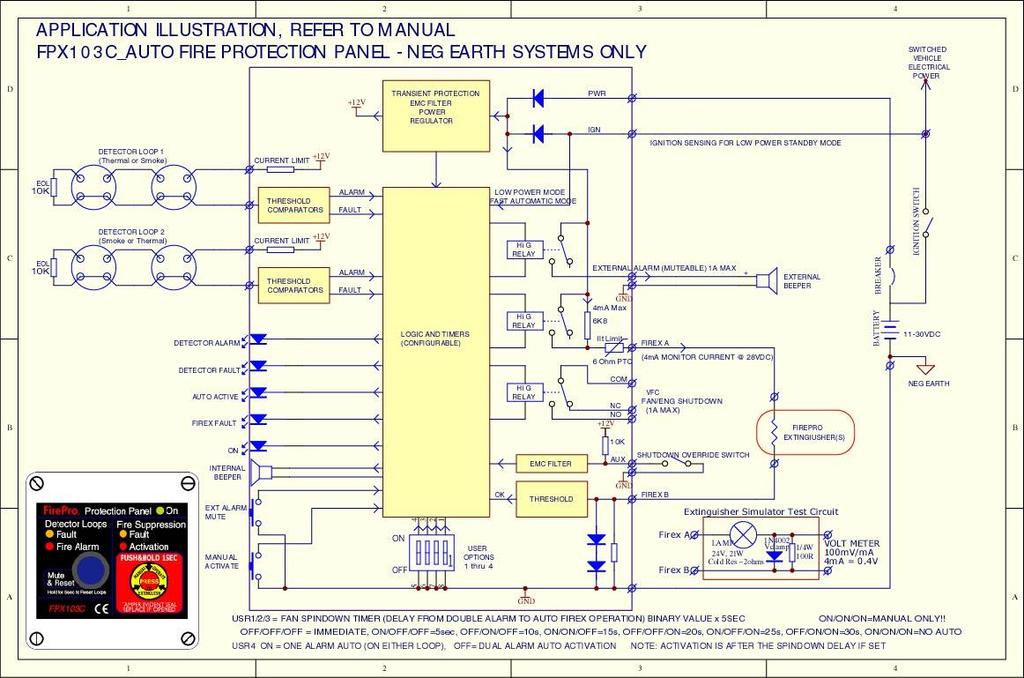
7 Typical Application wiring (Linear Heat Detector sensors)
FPX103C. Dual Loop Auto/Manual Fire Control Panel. Technical Manual
 FPX103C Dual Loop Auto/Manual Fire Control Panel Technical Manual FPX103C Auto DUAL LOOP AUTO/MANUAL FIRE CONTROL PANEL Iss 1.0 SUMMARY: Dual detection loops with full fault monitoring. Automatic extinguisher
Application, Installation, Operation & Maintenance Manual
 APPROVED BY:JBJ PRESCIENT III FIRE ALARM & GAS EXTINGUISHING CONTROL PANEL Application, Installation, Operation & Maintenance Manual PAGE 1 of 43 CONTENTS 1. INTRODUCTION... 3 2. GENERAL DESCRIPTION...
Installation, Operating and Maintenance Manual
 STATUS ZONES CONTROLS FIRE FAULT DISABLED FIRE 1 2 3 4 5 6 7 8 TEST FAULT DISABLED 1 5 BUZZER SILENCE RESET 1 2 TEST 2 6 LAMP TEST 3 SUPPLY 3 7 SYSTEM FAULT 4 8 SOUNDERS ACTIVATE/ SILENCE 4 FAULTS INSTRUCTIONS
PNC 1000 SERIES 2, 4, 8 Zone Fire Alarm Control Panel
 PNC 1000 SERIES 2, 4, 8 Zone Fire Alarm Control Panel INSTALLATION, OPERATION AND MAINTENANCE MANUAL Version: CN-PM-1000.VER1.1-12/2012 EN54 INFORMATION In accordance with EN 54-2 clause 13.7, the maximum
OPERATION AND INSTALLATION MANUAL
 EX+Plus 2 ZONE, 1AREA EXTINGUISHANT CONTROL PANEL OPERATION AND INSTALLATION MANUAL INTRODUCTION The Premier EX Plus is a 2 zone, single area panel for controlling the release of extinguishing gases in
Intelligent Security & Fire Ltd
 OPERATIONAL NOTES FOR CONCEPT FIRE PANEL. NOTE ON NEW FIRE PANELS, POSITION 1 ON THE SIX WAY INTERNAL OPTION SWITCH IS TURNED ON, DISABLING THE ZONAL SOUNDERS. TO ENABLE ZONAL SOUNDERS TURN OFF. Operation
HOKKIM INTEGRATED AMF CONTROL BOARD MANUAL FOR MODELS: HAMF-8 AND HAMF-4
 HOKKIM INTEGRATED AMF CONTROL BOARD MANUAL FOR MODELS: HAMF-8 AND HAMF-4 INTRODUCTION Thank you for purchasing the Hokkim Integrated Automatic Mains Failure Control Board model HAMF- 8 or HAMF-4. We shall
Control Panel Engineering and Commissioning Instructions
 Twinflex - V3 Fire Detection & Alarm System Control Panel Engineering and Commissioning Instructions (TO BE RETAINED BY THE COMMISSIONING ENGINEER) 26-0338 Issue 9 Fike s policy is one of continual improvement
M2500 Engine Controller Installation Manual
 M2500 Engine Controller Installation Manual Revision: 23-04-2012 Page 1 Contents 1 Preface... 4 2 Installation... 5 3 Terminal Connections... 6 4 Inputs... 7 4.1 Power Supply... 7 4.2 Mode/ Control Inputs...
GAS SUPRESSION CONTROL PANEL:
 GAS SUPRESSION CONTROL PANEL: MODEL NAME: COMPANY: DELTA 437/2, Main Road, Mandwali Fazalpur, Delhi-110092 Page 1 ABOUT THE PRODUCT ASES is very proud of to introduce DELTA the completely digital microprocessor
OPERATION & INSTALLATION MANUAL FOR ALARM PANEL M2AP01
 OPERATION & INSTALLATION MANUAL FOR ALARM PANEL M2AP01 Table of Contents Safety Instructions 4 Owner/Operator Responsibility 4 Specifications 5 Introduction 6 Installation Instructions 7 Setup 7 Wiring
DUAL MONITORED INPUT/OUTPUT UNIT BN-305
 DUAL MONITORED INPUT/OUTPUT UNIT BN-30 Interactive fire detection systems Product Datasheet Features Interactive For interfacing and controlling external units to Autronica s interactive fire detection
PSN-1000 & PSN 1000(E) Installation Manual
 Installation Manual") PSN-1000 & PSN 1000(E) Installation Manual Potter Electric Signal Company, LLC St. Louis, MO Customer Service: (866) 240-1870 Technical Support: (866) 956-1211 Fax: (314) 595-6999 www.pottersignal.com
PSN-1000 & PSN 1000(E) Installation Manual Potter Electric Signal Company, LLC St. Louis, MO Customer Service: (866) 240-1870 Technical Support: (866) 956-1211 Fax: (314) 595-6999 www.pottersignal.com
1200-HCM DIN RAIL MOUNTING FIRE SYSTEM MODULE Fire Detection & Extinguishant Control A R T PATOL LIMITED SUPPLY FAULT SOUNDER
 Application The unit is primarily intended for use where there is a requirement to integrate a limited fire protection function into a larger control equipment scheme, or in specialist applications where
Installation Guide for AL800UL-ADA. NAC Power Extender. Rev
 Installation Guide for AL800UL-ADA NAC Power Extender Rev. 090500 Overview: The Altronix AL800UL-ADA is an extremely cost effective 8 amps voltage regulated remote power supply /battery charger. The AL800UL-ADA
EX8. Instruction Manual: COMBINED FIRE & EXTINGUISHING CONTROL PANEL COMPLIES WITH BS EN PART 1 AND EN54 PARTS 2 & 4
 EX8 COMBINED FIRE & EXTINGUISHING CONTROL PANEL COMPLIES WITH BS EN 12094 PART 1 AND EN54 PARTS 2 & 4 Instruction Manual: Approved Document No: GLT.MAN-124 PAGE 2 INDEX INDEX... 3 Introduction... 4 Indications
Sigma. K1000 Series 1, 2, 4 & 6 Zone Fire Control Panels. Operation and Maintenance Manual. Man-1048 Issue 05 October 2009
 Sigma K1000 Series 1, 2, 4 & 6 Zone Fire Control Panels Operation and Maintenance Manual Man-1048 Issue 05 October 2009 CONTENTS Contents... Page Safety & Installation...2 Installation - continued...3
Control/Communicator Installation Manual
 DAS NETWORX NX-12 Control/Communicator Installation Manual General Description...2 Ordering Information...2 Option Definitions...3 Programming the LED Code Pads...5 Programming the NX-12...9 Types of Programming
HA-263K HA-263D. OWNER'S MANUAL Installation And Operation 8-ZONE ALARM CONTROL PANEL FOR HOME AND OFFICE PROTECTIONS OPEN THE CABINET FOR SERVICE
 D (OPERATION) INITIATE A DYNAMIC BATTERY TEST The system tests the back-up battery once every 24 hours. The owner can initiate a dynamic battery test at any time with the following codes while the system
MODEL 5100 VOTING LOGIC MODULE
 DESCRIPTION DESCRIPTION The SST Model 5100 Multi-Input Voting Logic Module is used to monitor the status of up to 14 different points in a hazard zone, and report when a selectable number of these points
Installation and user manual for the CF5000, MF5000 and FXP5000 range of fire panels
 CF5000, MF5000 and FXP5000 Installation and user manual for the CF5000, MF5000 and FXP5000 range of fire panels 16 zone panels Contents PANEL INSTALLATION...3 Installation...3 PANEL WIRING... 3 Mains power
Heat Pump Defrost Board Replacement Kit
 Bard Manufacturing Company, Inc. Bryan, Ohio 43506 8620-223 Heat Pump Defrost Board Replacement Kit KIT FEATURES This kit is made up of the current defrost control board 8201-129 and a new defrost sensor.
M2000 Engine Controller
 M2000 Engine Controller Integrated control and protection of diesel and gas engines for all purposes Especially suited for auxiliary generator sets 1 IN OPERATION 1 2 STARTFAIL 2 3 OVERSPEED RPM FAIL 3
FEC400 Series. Installation Manual
 FEC400 Series Conventional microprocessor controlled fire detection and alarm panels with extinguishing control Installation Manual Version 2.3 / August 2004 Aritech is a GE Interlogix brand. http://www.geindustrial.com/ge-interlogix/emea
Conventional Fire Alarm System 2014 V1.2
 Conventional Fire Alarm System 2014 V1.2 Product Overview Control Panel 2 Conventional Fire Panel GST102A 2 zone Fire panel GST104A 4 zone Fire panel GST108A 8 zone Fire panel GST116A 16 zone Fire Panel
Premier Hazard STC Instructions
 PREMIER HAZARD Ltd Bessingby Industrial Estate Bridlington YO16 4SJ Tel: +44 (0) 113 239 1111 Fax: +44 (0) 113 239 1131 www.premierhazard.co.uk info@premierhazard.co.uk Premier Hazard STC Instructions
DUAL MONITORED INPUT/OUTPUT UNIT BN-305-2
 DUAL MONITORED INPUT/OUTPUT UNIT BN-305-2 Interactive fire detection systems Product Datasheet Features Interactive For interfacing and controlling external units to Autronica s interactive fire detection
Reflective Optical Beam Smoke Detector User Guide
 Reflective Optical Beam Smoke Detector User Guide 1. Installation IMPORTANT NOTE: The infrared beam path MUST be kept clear of obstructions at all times! Failure to comply may result in the system initiating
EXTINGUISHING AGENT RELEASE MODULE
 EXTINGUISHING AGENT RELEASE MODULE Operation, Installation & Programming Manual Revision 3.00 Distributors For: 18-20 Brookhollow Ave telephone 02 8850 2888 www.firesense.com.au Baulkham Hills NSW 2153
TECHNICAL DATA OBSOLETE
 Deluge Devices 270a 1. PRODUCT NAME VIKING PAR-3 Available since 1991 2. MANUFACTURED FOR: THE VIKING CORPORATION 210 N. Industrial Park Road Hastings, Michigan 49058 U.S.A. Telephone: (269) 945-9501 (877)
PRODUCT INSTRUCTIONS. Fire Door Control Panel (FDCP) Stock Code Description Doc No: PI-115. Ellard Fire Door Control Panel Ellard Slave Repeater Unit
 Stock Code Description Doc No: PI-115. Ellard Fire Door Control Panel Ellard Slave Repeater Unit") PRODUCT INSTRUCTIONS Fire Door Control Panel (FDCP) Floats Rd, Wythenshawe, Manchester. M23 9WB T: 44 (0)161 945 4561 F: 44 (0)161 945 4566 Stock Code Description Doc No: PI115 00133 00134 Ellard Fire
PRODUCT INSTRUCTIONS Fire Door Control Panel (FDCP) Floats Rd, Wythenshawe, Manchester. M23 9WB T: 44 (0)161 945 4561 F: 44 (0)161 945 4566 Stock Code Description Doc No: PI115 00133 00134 Ellard Fire
AL800ULADA. NAC Power Extender. Installation Guide
 AL800ULADA NAC Power Extender Installation Guide Rev. 122000 AL800ULADA - NAC Power Extender Overview: The Altronix AL800ULADA is an extremely cost effective 8 amp voltage regulated remote power supply/battery
30.45 Electric Release PDRP-2001
 The PDRP-2001 Fire Alarm Control Panel (FACP) is a six-zone control panel for single and dual hazard deluge and preaction applications. The FACP is compatible with conventional input devices (2-wire or
USER MANUAL COMBINED FIRE & EXTINGUISHING CONTROL PANEL COMPLIES WITH BS EN PART 1 & EN54 PARTS 2 & 4
 PREMIER EX8 EXTINGUISHING PANEL USER MANUAL COMBINED FIRE & EXTINGUISHING CONTROL PANEL COMPLIES WITH BS EN 12094 PART 1 & EN54 PARTS 2 & 4 USER MANUAL Approved Document No: GLT.MAN-132 INDEX Extinguishing
ZIOU/230 - MAINS IO INSTRUCTION MANUAL
 Description ZIOU/230 - MAINS IO INSTRUCTION MANUAL The Mains IO Modules are fully monitored loop powered devices which permit the interfacing of third party equipment with the Fire Alarm Control panel
RANGER 8600 DOWNLOADABLE CONTROL COMMUNICATOR INSTALLATION MANUAL
 RANGER 8600 DOWNLOADABLE CONTROL COMMUNICATOR INSTALLATION MANUAL TABLE OF CONTENTS GENERAL DESCRIPTION... 2 STANDARD AND OPTIONAL PARTS LIST... 2 PARTS DIAGRAM... 3 TERMINAL DRAWING AND SPECIAL NOTES...
Emerald 3000 MK3 GJD010 Lighting Controller
 Emerald 3000 MK3 GJD010 Lighting Controller SPECIFICATION SUPPLY: 230 Vac 50Hz via ELCB/MCB - unit fused at 13A 12VDC@ 100mA: GJD Opal XL (6mA) or Elite Detectors (10mA) Optional external 12VDC piezo sounder
TABLE OF CONTENTS TABLE OF CONTENTS 1
 TABLE OF CONTENTS TABLE OF CONTENTS 1 FEATURES 2 Keypad Programmable... 2 EEPROM Memory... 2 Static/Lightning Protection... 2 Supervision... 2 Operation... 2 SPECIFICATIONS 2 PC1550 Control Panel... 2
TECHNICAL DATA. Humidity: 85% Relative Humidity (non-condensing) at 90 F (32 C) maximum.
 at 90 F (32 C) maximum.") September 29, 1997 Firecycle III 433 a 1. PRODUCT NAME VIKING Model E-1 Manufactured 1997 Present 2. MANUFACTURED FOR THE VIKING CORPORATION 210 N Industrial Park Road Hastings, Michigan 49058, U.S.A.
September 29, 1997 Firecycle III 433 a 1. PRODUCT NAME VIKING Model E-1 Manufactured 1997 Present 2. MANUFACTURED FOR THE VIKING CORPORATION 210 N Industrial Park Road Hastings, Michigan 49058, U.S.A.
AL802ULADA. NAC Power Extender. Installation Guide. (See Application Guide for additional information) Rev
 Rev") AL802ULADA NAC Power Extender Installation Guide (See Application Guide for additional information) Rev. 031703 Overview: The Altronix AL802ULADA is an extremely cost effective 8 amp voltage regulated
AL802ULADA NAC Power Extender Installation Guide (See Application Guide for additional information) Rev. 031703 Overview: The Altronix AL802ULADA is an extremely cost effective 8 amp voltage regulated
Remote NAC Power Supply D7038
 Operation and Installation Guide Remote NAC Power Supply D7038 D7038 REMOTE NAC POWER SUPPLY Page 2 2005 Bosch Security Systems Contents Contents 1.0 Overview...5 1.1 Module Control...5 1.1.1 Option Bus
0$; Installation Instructions. Computerized Control Panel '(6&5,37,21 63(&,),&$7,216 DE5011 1
,&$7,216 DE5011 1") 0$; Computerized Control Panel Installation Instructions '(6&5,37,21 The MAX-5 is a highly reliable, cost effective control panel for residential and commercial applications. Besides being simple to install
0$; Computerized Control Panel Installation Instructions '(6&5,37,21 The MAX-5 is a highly reliable, cost effective control panel for residential and commercial applications. Besides being simple to install
Flopurge TS. Operation Manual
 Flopurge TS Operation Manual Part Number 079-0204 Spectron Gas Control Systems United Kingdom Unit 4, Herald Court, University of Warwick Science Park, Coventry, CV4 7EZ +44 (0)24 7641 6234 sales@spectron-gcs.com
EC Series Wall Unit Humidifier
 Read and Save These Instructions EC Series Wall Unit Humidifier Controller Operation Manual SEASONAL DRAIN SAFETY CIRCUIT OPEN POWER FILL VALVE OPEN WATER LEVEL FULL COOL DOWN CYCLE DRAIN VALVE OPEN HEATER
Public Safety DAS Annunciator Panel
 Public Safety DAS Annunciator Panel 120 VAC Models: 1221-A, 1221-B, 1221-C Revision D 91117 48 VDC Models: 1221-A-48, 1221-B-48, 1221-C-48 24 VDC Models: 1221A-24, 1221-B-24, 1221-C-24 CAUTION: (Read This
SYSTEM MANUAL FT1-SB. Single Zone Fire Alarm System
 SYSTEM MANUAL FT1-SB Single Zone Fire Alarm System DOCUMENT HISTORY Issue Date Description Written By Checked By Draft 0 2/9/2008 Original Document. A. Shenouda C. Orr Issue 1 4/11/2011 Update drawing
MINERVA MX. 800 Series Ancillary Equipment
 An extensive range of ancillary modules has been specifically designed for use with the MX range of Fire Controllers. The 800 range of ancillary modules provide the MX Fire Controller with a wide degree
ICS Regent. Fire Detector Input Modules PD-6032 (T3419)
") ICS Regent Fire Detector Input Modules (T3419) Issue 1, March, 06 Fire detector input modules provide interfaces for 16 fire detector inputs such as smoke detectors, flame detectors, temperature detectors,
ICS Regent Fire Detector Input Modules (T3419) Issue 1, March, 06 Fire detector input modules provide interfaces for 16 fire detector inputs such as smoke detectors, flame detectors, temperature detectors,
FTEN1, FTEN2, & FTEN4 1, 2 & 4 ZONE FIRE DETECTION AND ALARM CONTROL PANELS
 QUICK USER GUIDE FOR, 2 & 4 ZONE PANELS INDICATORS COLOUR INDICATION MON FAULT Yellow On when a fault condition has occurred, or if no other fault Led is on, this indicates 24v auxiliary fuse failure.
705 Emmett Street Bristol, CT DynaLock MODEL 3101C-TJ101 DELAY EGRESS SYSTEM WIRING INSTRUCTIONS
 BASIC SET-UP 1. Remove the Electronics Cover to expose the circuit board assembly. C L C 2. - System Selector Switches The selector switches (S3) which control major system functions are factory set to
Installation Instructions
 0$;0$; Computerized Multi-Function Alarm Control Panels Installation Instructions '(6&5,37,21$1'&$3$%,/,7,(6 The MAX-8 and MAX-16 are reliable, cost-effective control panels for residential and commercial
Intruder - Fire - Water Combined Alarm
 65 Intruder - Fire - Water Combined Alarm Installation Manual and User Operating Instructions TALE OF CONTENTS Page First Power-Up 2 Power Supply Unit 3 Input & Detection Circuits 3 Output & Alarm Circuits
Model 17A00 Expansion Enclosure
 HOME AUTOMATION, INC. Model 17A00 Expansion Enclosure Installation Manual Document Number 17I00-1 Rev A March, 2002 Home Automation, Inc. Model 17A00 Expansion Enclosure Installation Manual Document Number
AL600ULADA. NAC Power Extender. Installation Guide
 AL600ULADA NAC Power Extender Installation Guide Rev. 122000 AL600ULADA - NAC Power Extender Overview: The Altronix AL600ULADA is an extremely cost effective 6.5 amp voltage regulated remote power supply/battery
FIRE ALARM CONTROL PANEL. COMPLIES WITH EN54 part 2 & part 4 MEETS THE FUNCTIONAL REQUIREMENT OF BS:EN 5839 part 1 INSTALLATION MANUAL
 FIRE ALARM CONTROL PANEL COMPLIES WITH EN54 part 2 & part 4 MEETS THE FUNCTIONAL REQUIREMENT OF BS:EN 5839 part 1 INSTALLATION MANUAL CONTENTS 1. INTRODUCTION. 3 1.1 HANDLING THE PCBS 1.2 USING THIS MANUAL
This wiring diagram describes circuit connections for all models of the Series Quaestor-SZU Releasing Fire Control
 File: S8485 Wiring Diagram This wiring diagram describes circuit connections for all models of the Series Quaestor-SZU Releasing Fire Control Panel. The operation of this product is intended for indoor
Installation Manual RINS1211-4
 Installation Manual 2x 2x RINS1211- Contents Page System Overview Technical Specification 5 Overview 6 The Control Panel 6 The Printed Circuit Board The Tamper Spring and Connections 8 Connections 9 Transformer
RANGER 7600 DOWNLOADABLE CONTROL COMMUNICATOR INSTALLATION MANUAL
 RANGER 7600 DOWNLOADABLE CONTROL COMMUNICATOR INSTALLATION MANUAL TABLE OF CONTENTS 1. TABLE OF CONTENTS... P.1 2. GENERAL DESCRIPTION... P.2... 3. STANDARD AND OPTIONAL PARTS LIST... P.2... 4. FEATURE
Model 3300 Technical Support and Installation Manual
 Model 3300 Technical Support and Installation Manual Manual # T15011 Document Revision: A1 1. OVERVIEW 1 2. BASIC OPERATION 1 2.1 General 1 2.2 Field-of-View 2 2.3 Range 2 2.4 Environment 2 2.5 Configuration
Models NFPA 1221-A, NFPA 1221-B Public Safety DAS Annunciator Panel. Revision E 61117
 Models NFPA 1221-A, NFPA 1221-B Public Safety DAS Annunciator Panel Revision E 61117 CAUTION: (Read This First) This panel has been designed to make it nearly bullet proof to mistakes made when wiring
MODEL KP-200 VANDAL RESISTANT & WEATHERPROOF FLUSH MOUNT DIGITAL KEYPAD DESIGNED FOR ACCESS CONTROL APPLICATIONS
 MODEL KP-200 VANDAL RESISTANT & WEATHERPROOF FLUSH MOUNT DIGITAL KEYPAD DESIGNED FOR ACCESS CONTROL APPLICATIONS OPERATES ON 12 OR 24 VOLTS AC/DC, AUTO VOLTAGE SENSING FULLY PROGRAMMABLE FROM THE KEYPAD
THANK YOU FOR VOTING TEXECOM INSTALLATION MANUAL. Security Control Panel with Communicator Interface
 THANK YOU FOR VOTING TEXECOM INSTALLATION MANUAL Security Control Panel with Communicator Interface Table of Contents Table of Contents Section Page 1 Programming Summary 4 1.1 Programming Menu 4 1.1.1
highline SVCS-1 INSTALLATION & USER MANUAL SMOKE VENT CONTROL SYSTEM * enclosure design may vary software version: SVCS1r6 SVCS1r7 SVCS1r10
 highline WINDOW CONTROLS INSTALLATION & USER MANUAL SMOKE VENT CONTROL SYSTEM SVCS-1 * enclosure design may vary software version: SVCS1r6 SVCS1r7 SVCS1r10 CERTIFICATE OF COMPLIANCE SVCS-1 We the undersigned
BT1 SINGLE ZONE FIRE ALARM SYSTEM OPERATORS MANUAL
 BT1 SINGLE ZONE FIRE ALARM SYSTEM OPERATORS MANUAL 26 Aug 2015 V1.8 Page 1 SECTION CONTENTS PAGE NO. 1.0 SYSTEMS DESCRIPTION 1.1 General descriptions 2 1.2 Master Alarm PCB 2 1.3 Zone Display Board 2 1.4
RELEASE DEVICES RELEASE DEVICE-WPS MODELS A/B INSTALLATION MANUAL U.L. LISTED CANADIAN LISTED CSFM: :100 GENERAL DESCRIPTION:
 RELEASE DEVICES MADE IN THE U.S.A. RELEASE DEVICE-WPS MODELS A/B INSTALLATION MANUAL U.L. LISTED CANADIAN LISTED CSFM: 7300-1418:100 GENERAL DESCRIPTION: S/N: The "WPS" World Power Series, Time Delay Release
MULTIFUNCTION ALARM SYSTEM TYPE ED510 FIRE LEVEL GAS ZONE 1 ZONE 2 ZONE 1 ZONE 2 SENSOR 1 SENSOR 2 ALARM FAULT TEST ON TEST OFF
 MULTIFUNCTION SYSTEM TYPE ED510 FIRE LEVEL GAS ZONE 1 ZONE 1 SENSOR 1 SENSOR 2 HIGH HIGH POWER O/C FAULT O/C FAULT FAULT FAULT LOW LOW SOUNDER CCT FAULT S/C FAULT S/C FAULT TEST ON TEST ON FAULT FAULT
End To End Optical Beam Smoke Detector. Additional Information
 End To End Optical Beam Smoke Detector Additional Information EN 1. Multiple Zone Wiring When using more than one System Controller on a single zone of a conventional Fire Control Panel (FCP), it is important
MR-2602 Two Zone Fire Alarm Control Panel
 MR-2602 Two Zone Fire Alarm Control Panel Installation Manual Secutron LT-2015 Rev.3 July 2010 Table of Contents 1 Introduction 1.1 The MR-2602 Fire Alarm Control Unit... 11 1.1.1 General features...
SECURIT 700L PLUS ENGINEERING MANUAL
 SECURIT 700L PLUS ENGINEERING MANUAL C & K Systems Ltd 13/03/97 C031-096-02 NEW ENHANCED FEATURE SET Securit 700L PLUS Engineering instructions INTRODUCTION The Securit 700L is a microprocessor intruder
ESP TECHNOLOGIES LIMITED
 Alarm Technology ESPAN-01 Series Annunciator System Combination type User Manual (Rev. 1) ESP TECHNOLOGIES LIMITED www.esptechno.com Content Page Introduction 2 General Description 2 Overview - Annunciator
FR-4000 & FR-8000 Fire Alarm Monitor Installation Manual
 FR-4000 & FR-8000 Fire Alarm Monitor Installation Manual Table of Contents Introduction 1 System Components 2 Wiring Block Diagram 3 Connection Diagram for One Sensor 4 Connection Diagram for Multiple
DS3MX-E-I. Installation Guide. 3 Zone Mini Control Panel
 DS3MX-E-I EN Installation Guide 3 Mini Control Panel DS3MX-E-I Installation Guide 1.0 General Information EN 2 1.0 General Information The DS3MX is a three zone mini control panel, which can be installed
DEIF A/S. Technical Manual. Type EC-2 Engine Control Unit D. Technical Manual
 Technical Manual Type EC-2 Engine Control Unit 4189340232D DEIF A/S Technical Manual DEIF A/S Tel.: (+45) 9614 9614 Frisenborgvej 33, DK-7800 Skive Fax: (+45) 9614 9615 Denmark E-mail: deif@deif.com Contents
Fire Burglary Instruments Inc. XL-2G Gold Control/Communicator Installation Training Seminar Rev. 5/96
 Fire Burglary Instruments Inc. XL-2G Gold Control/Communicator Installation Training Seminar Rev. 5/96 XL-2G Gold Product Overview 7 Zones (6 programmable + panic or keyswitch zone) Fast Loop Response
RED1. Technical Support And Installation Manual. Models ST, E1, E2, E3, E4, and 420. Approved
 RED1 Models ST, E1, E2, E3, E4, and 420 Technical Support And Installation Manual 210111 FM Approved 1. OVERVIEW 1 2. BASIC OPERATION 3 2.1 General 3 2.2 Field-of-View 4 2.3 Range 4 2.4 Environment 4 2.5
INSTALLATION MANUAL & PROGRAM RECORD SHEET
 INSTALLATION MANUAL & PROGRAM RECORD SHEET TABLE OF DESCRIPTION CONTENTS PAGE WIRING MANUAL 2-6 MENU CHART 7 INSTALLER FUNCTIONS 8 MENU 1 SYSTEM TIMES 9 MENU 2 ZONE CONFIGURATION 10-14 MENU 3 SYSTEM OPTIONS
Gas Safety Products. Installation, operating and maintenance 11/18/2015. Merlin 1000S+ Gas Utility & Electrical Isolation Controller
 Gas Safety Products Installation, operating and maintenance 11/18/2015 American Gas Safety LLC 1 Table of contents 1 General information... 3 2 Installation... 3 2.1 Panel Mounting.... 3 2.2 Power Supply....
CPS-1 USER S MANUAL AIR INLET / CURTAIN CONTROL
 CPS-1 USER S MANUAL AIR INLET / CURTAIN CONTROL temperature / static pressure DIFF Opn Clo ALARM HI F2 DELAY ALARM LO OPEN DELAY CLOSE ADJUST Varifan + CPS-1 CPS-1 Although the manufacturer has made every
TECHNICAL DATA. multi-hazard. model vfr400. Release Control Panel 290a. January 16, 2014
 January 16, 2014 Release Control Panel 290a 1. Description The Viking VFR400 is a microprocessor based releasing control panel for use on preaction, deluge, Surefire, Firecycle multicycle sprinkler systems,
Intelligent Security & Fire Ltd
 full installation, commissioning and operating manuals can be downloaded from www.haes-systems.co.uk combined addressable / conventional fire alarm control panel User Guide Approved Document No. MFBU-04
4 & 8-POINT ANNUNCIATORS Instruction Manual
 4 & 8-POINT ANNUNCIATORS Instruction Manual 8 Field Selectable Sequences All Common ISA Sequences 4 or 8-Point (Channel) Monitoring Free Replaceable Message Labels Type 4X, NEMA 4X, IP65 Front Universal
Danfoss gas detection units
 Data sheet Danfoss gas detection units Types GD Premium, Premium+, Premium Duplex, Premium Remote, Premium Flex and Premium Uptime The Premium line gas detection units are used for monitoring and warning
Flostop TS D7E and A8E. Operation Manual
 Flostop TS D7E and A8E Operation Manual United Kingdom Spectron Gas Control Systems Ltd, Unit 4, ATU1, University of Warwick science Park, Coventry, +44 (0) 24 7641 6234 sales@spectron-gcs.com Germany
Instructions R8471J Gas Controller for use with Model OPECL Open Path Eclipse IR Gas Detector 1.1 1/
 Instructions R8471J Gas Controller for use with Model OPECL Open Path Eclipse IR Gas Detector 1.1 1/08 Table Of Contents Section I Installation and Startup.................. 1 INSTALLATION............................................
Ammonia Leak Detector Manual
 Ammonia Leak Detector Manual Document No. 70-PHW-1023-R2.5 No part of this publication may be reproduced, stored in a retrieval system, or transmitted, in any form or by any means, electronic, mechanical,
LEAKMONITOR MULTIZONE WATER LEAK DETECTION ALARM PANEL INSTALLATION AND USER OPERATION MANUAL
 LEAKMONITOR MULTIZONE WATER LEAK DETECTION ALARM PANEL INSTALLATION AND USER OPERATION MANUAL The LeakMonitor alarm panel is a microprocessor controlled fully adjustable alarm system suitable for multizone
I/O ZONE 560/583 AND OPERATION MANUAL
 UPM I I/O ZONE 560/583 INSTALLATION AND OPERATION MANUAL 1 UNIT PROTECTION MODULE HARDWARE OPERATION IMPORTANT: This manual is for UPM board part numbers 8733 800 259. See controller label as shown in
50M Integrated Single or Two-Stage HSI Integrated Furnace Control Kit INSTALLATION INSTRUCTIONS
 50M56-743 Integrated Single or Two-Stage HSI Integrated Furnace Control Kit INSTALLATION INSTRUCTIONS FAILURE TO READ AND FOLLOW ALL INSTRUCTIONS CAREFULLY BEFORE INSTALLING OR OPERATING THIS CONTROL COULD
Carbon Monoxide Transmitter
 Introduction The CO Transmitter uses an electrochemical sensor to monitor the carbon monoxide level and outputs a field-selectable 4-20 ma or voltage signal. The voltage signal may also be set to 0-5 or
WARNING Important Safety Information
 Builder Series Non-Programmable Thermostats MODEL 1000 MODEL 0 1 2 3 4 Single Stage Heat / Cool Conventional and Heat Pump Multi-Stage 2 Heat / 1 Cool Conventional and Heat Pump Before Installing, Programming
HEXA PROGRAMMING: STREAMLINED SECTION PROGRAMMING
 -961212-0004 SOFTWARE VERSION 3.10 CONTROL PANEL RESET: Installer lock must be unlocked. ( 058: enter any value other than 147) Power down reset (1) Remove battery and AC to power down the unit. (2) Connect
TO ARM/DISARM ALARM The alarm is activated by pressing BUTTON 1 on the remote control transmitter once. The blinkers will flash once, and the
 INSTRUCTION MANUAL FOR Code Hopping Remote Control Car Alarm with Two Stage Impact Sensor, Battery Backup Siren & 2 Point Engine Immobilisation N517 Build SYDNEY Date: / AUSTRALIA Version 2.0 TO ARM/DISARM
SOLID STATE SECURITIES, INC. THE "SS90" SERIES RELEASE DEVICES MADE IN THE U.S.A. SS90-WPS MODEL A/B INSTALLATION MANUAL
 S S S S S S LISTED L * PATENT PENDING S S 90 OLID TATE ECURITIES, INC SOLID STATE FAIL-SAFE UNIT U 99Y9 RESET RELEASING DEVICE SOLID STATE SECURITIES, INC. THE "SS90" SERIES RELEASE DEVICES MADE IN THE
5000 SERIES 8 ZONE INSTRUCTION MANUAL
 5000 SERIES 8 ZONE INSTRUCTION MANUAL NESS SECURITY PRODUCTS 4/167 PROSPECT HIGHWAY SEVEN HILLS. 2147 NSW AUSTRALIA SYDNEY Phone: (02) 8825 9222 (Head Office) BRISBANE Phone: (07) 3343 7744 MELBOURNE Phone:
USER MANUAL CEF AP28 CONTROL PANEL
 USER MANUAL CEF AP28 CONTROL PANEL AP28 WARNINGS This product has mains voltage present within the housing. Please take the necessary precautions in not allowing any liquid to spill on or into the housing.
Gas Safety Products. Installation, operating and maintenance. Merlin 1000S+i Gas & Electric Utility Controller. Rev: 03 Date:
 Gas Safety Products Merlin 1000S+i Gas & Electric Utility Controller Installation, operating and maintenance Rev: 03 Date: 14-08-18 1 Table of contents 1 General information... 3 2 Installation... 3 2.1
Operator: Save these instructions for future use!
 WHITE-RODGERS 50A55-474 & 50A55-571 Integrated Furnace Controls INSTALLATION INSTRUCTIONS Operator: Save these instructions for future use! FAILURE TO READ AND FOLLOW ALL INSTRUCTIONS CAREFULLY BEFORE
DIESEL ENGINE CONTROL UNIT DCU USER S MANUAL - N-2000 Lillestrøm, Norway Tel: (+47) Fax: (+47)
 Fax: (+47)") DIESEL ENGINE CONTROL UNIT DCU 205 - USER S MANUAL - N-2000 Lillestrøm, Norway Tel: (+47) 64 84 52 00 Fax: (+47) 64 84 52 12 office@auto-maskin.no - 1 - TABLE OF CONTENTS 1. INTRODUCTION TO THE DCU 205...4
DIESEL ENGINE CONTROL UNIT DCU 205 - USER S MANUAL - N-2000 Lillestrøm, Norway Tel: (+47) 64 84 52 00 Fax: (+47) 64 84 52 12 office@auto-maskin.no - 1 - TABLE OF CONTENTS 1. INTRODUCTION TO THE DCU 205...4
Interface and EOL Modules 8
 Interface and EOL Modules Interface Modules Series 420 25 Interface Modules Series 100 291 EOL Modules 293 254 Interface and EOL Modules Interface Modules Series 420 Interface Modules Serie 420 Interface
FIREPRO INSTALLATION MANUAL FIRE ALARM CONTROL PANEL INSTALLATION MANUAL. Approved Document No. GLT Issue: 1. 8 Author: NRPJ Date: 7/ 3/201 4
 FIRE ALARM CONTROL PANEL INSTALLATION MANUAL Approved Document No. GLT -201-7-3 Issue: 1. 8 Author: NRPJ Date: 7/ 3/201 4 CONTENTS 1. INTRODUCTION... 1.1 HANDLING THE PCBS... 1.2 USING THIS MANUAL... 1.3