Capacitive leakage detectors of the Leckmaster range for installation in normally dry rooms
|
|
|
- Mervyn Rogers
- 5 years ago
- Views:
Transcription
 Tel. +49 6325 188-01 Fax +49 6325 6396 contact@jola-info.de www.jola-info.de A-1 31-6-0")
1 Capacitive leakage detectors of the Leckmaster range for installation in normally dry rooms Jola Spezialschalter GmbH & Co. KG Klostergartenstr Lambrecht (Germany) Tel Fax A
2 Contents Page Leckmaster - general information Application examples Leckmaster - capacitive suspension sensor with stainless steel housing Capacitive suspension sensor COW/L Leckmaster - capacitive suspension sensor with plastic housing Capacitive suspension sensor OWE 2/C Leckmaster 101 relay Installation, operating and maintenance instructions The units described in this documentation may only be installed, connected and started up by suitably qualified personnel! Subject to deviations from the diagrams and technical data. The details in this brochure are product specification descriptions and do not constitute assured properties in the legal sense
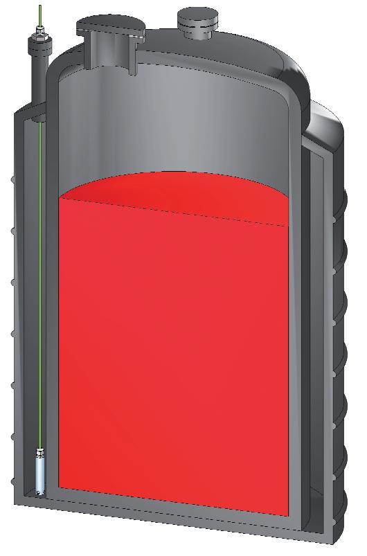
3 Leakage detectors of the Leckmaster range - general information with integrated cable break monitoring for conductive and non-conductive liquids; can basically be used for the detection of all low-viscosity liquids for such tasks as signalling the presence of fuel oil on the floor of a tank room or in a collection tub located underneath a fuel oil burner. The Leckmaster leakage detectors consist of 2 components: a COW/L or OWE 2/C sensor and a Leckmaster 101 relay. The COW/L and OWE 2/C sensors are designed for connection to the Leckmaster 101 relay. They work on a capacitive basis. If several sensors are used, a separate Leckmaster 101 relay is required for each sensor. The COW/L and OWE 2/C sensors can be mounted either upright on the floor (using the stand offered by Jola as an option) or freely suspended by their cable above the floor. Please follow the installation, operating and maintenance instructions (see page ). The COW/L and OWE 2/C sensors should only be used in normally dry surroundings e.g. in collection rooms or collection tubs. The Leckmaster 101 relay is designed for U-bar mounting or surface mounting. The various operating statuses are shown by coloured LEDs. Areas of application: All organic and inorganic liquids with specific dielectric constants between 1.8 and 109. Prerequisite is that these liquids, dependent on the ambient temperature, are present in fluid form, and that the sensors to be used will be sufficiently wetted. Response height is approx. 12 mm


4 Leakage detection with Leckmaster capacitive sensors Application examples


5 Leakage detection with Leckmaster capacitive sensors Application example

6 Leakage detection with Leckmaster capacitive sensors Application example


7 COW/L and OWE 2/C sensors COW/L COW/L with mounting stand OWE 2/C OWE 2/C with mounting stand
8 COW/L sensor Technical data Housing Connecting cable Functional principle Self-capacitance Self-inductance Protection class for the electronics sealed in the housing IP 65 Temperature range 20 C to + 60 C Response height from bottom edge of housing Mounting accessory Max. length of connecting cable between relay and sensor EMC COW/L stainless steel 316 Ti and PTFE oil-resistant PVC cable 2 x 0.75 mm², cable length 5 metres, longer cable on request, other types of cable on request capacitive sensor with stainless steel cylindrical capacitor Ceq = 80 nf nf per metre of connecting cable Leq = μh per metre of connecting cable 12 mm (depending on the dielectric constant of the liquid) stand made of stainless steel 316 Ti (optional) 1,000 metres, longer on request for interference emission in accordance with the appliancespecific requirements for households, business and commerce as well as small companies, and for interference immunity in accordance with the appliance-specific requirements for industrial companies. Optional: mounting stand made of stainless steel 316 Ti for COW/L View A (smaller scale) ~ Ø 28 Ø 25 3 Ø 28 Ø Ø 16 Ø 18 Ø 6 R x 120 Ø ~ 145 Stand, optional, with these or any other dimensions 55 A
9 OWE 2/C sensor Technical data OWE 2/C Housing Connecting cable Functional principle Self-capacitance Self-inductance PP and cast resin oil-resistant PVC cable 2 x 0.75 mm², cable length 5 metres, longer cable on request, other types of cable on request capacitive sensor with gold-plated capacitor plates on epoxy resin backing material Ceq = 80 nf nf per metre of connecting cable Leq = μh per metre of connecting cable Protection class for the electronics sealed in the housing IP 65 Temperature range 20 C to + 60 C Response height from bottom edge of housing 12 mm (depending on the dielectric constant of the liquid) Mounting accessory stand made of stainless steel 316 Ti (optional) Max. length of connecting cable between relay and sensor 1,000 metres, longer on request EMC for interference emission in accordance with the appliancespecific requirements for households, business and commerce as well as small companies, and for interference immunity in accordance with the appliance-specific requirements for industrial companies Optional: mounting stand made of stainless steel 316 Ti for OWE 2/C (diagrams with smaller scale compared to adjacent drawings) ~ ~ 150 Ø 6 76 Ø 5 30 ~ 97 ~ ~
10 Leckmaster 101 relay with cable break monitoring and switchable self-hold, for connection of a COW/L or OWE 2/C sensor Switching unit for U-bar mounting or surface mounting, with connection terminals on top, with switchable self-hold function, and with built-in LEDs for signalling the operating status. The appliance is designed for switch cabinet installation or mounting in an appropriate protective housing and may therefore not be installed in other locations. It is only suitable for use in clean environments. Self-hold: If the switch for self-hold is switched on, an alarm is stored. The relay continues to signal the alarm even if the cause of the alarm (e.g. the presence of oil) is no longer present in other words, if the sensor is dry again. The alarm is reset by switching off the switch for selfhold. If the switch for self-hold is not switched on, the alarm is not maintained when the cause of the alarm has been remedied but is reset. Technical data Leckmaster 101 Alternative supply voltages (AC versions: - AC 230 V (delivered if no other supply voltage is specified terminals 15 and 16; in the order) or DC versions: - AC 240 V or - terminal 15:, - AC 115 V or - terminal 16: +) - AC 24 V or - DC 24 V or in these two cases, the unit must only be - DC 12 V or } connected to a low safety voltage which corresponds to the safety regulations relating to the application - further supply voltages on request Power input approx. 3 VA Control circuit (terminals 6 and 8) 2 terminals (under safety extra low voltage SELV) acting on 1 output relay with switchable self-hold Sensor connection (in line with EN ): no-load voltage DC 8.4 V (safety extra low voltage SELV) short-circuit current < 10 ma response hysteresis 1.5 ma 1.8 ma Cable break monitoring Controlled circuit (terminals 9, 10, 11) I < 0.15 ma 1 single-pole potential-free changeover contact based on the quiescent current principle Switching status indicators 3 LEDs (see next page) Switching voltage max. AC 250 V Switching current max. AC 4 A Switching capacity max. 500 VA Housing insulating material, 75 x 55 x 110 mm Connection terminals on top of housing Protection class IP 20 Mounting clip attachment for U-bar to DIN and EN or fastening via two boreholes Mounting orientation any Temperature range 20 C to + 60 C Max. length of connecting cable between relay and sensor EMC 1,000 metres, longer on request for interference emission in accordance with the appliancespecific requirements for households, business and commerce as well as small companies, and for interference immunity in accordance with the appliance-specific requirements for industrial companies.


11 Connection diagram - Leckmaster 101 relay brown yellow LED flashes = cable break green LED lights = OK status red LED lights = leakage alarm black COW/L or OWE 2/C Supply voltage Position of contact when Leckmaster 101 without voltage Position of the output contact of the Leckmaster 101 relay Relay Leckmaster 101 Cable break OK status Alarm status without voltage LEDs dark: yellow LED flashes: green LED lights: red LED lights: Leckmaster 101 Leckmaster 101 Leckmaster 101 Leckmaster 101 without voltage, under voltage, under voltage, under voltage, output relay cable break in sensor sensor not activated, sensor activated, not energised or its connecting cable, output relay output relay output relay not energised energised not energised
12 Installation, operating and maintenance instructions for the capacitive leakage detectors in the Leckmaster range 1. Areas of application: All organic and inorganic liquids with specific dielectric constants between 1.8 and 109. Prerequisite is that these liquids, dependent on the ambient temperature, are present in fluid form, and that the sensors to be used will be sufficiently wetted. Response height is approx. 12 mm. The sensors may only be used in a temperature range between 20 C and + 60 C. The admissible temperature range for use of the Leckmaster 101 relay is from 20 C to + 60 C. It is, however, advisable to use the unit in frost-free rooms or in heated protective boxes. 2. Installation site: The COW/L and OWE 2/C sensors should only be used in normally dry surroundings e.g. in collection rooms or collection tubs. The COW/L and OWE 2/C sensors should be installed at the lowest point to ensure rapid leakage alarm. 3. Installation (see also the sample applications on pages to ): The COW/L and OWE 2/C sensors can be installed using the standard mounting stands offered by JOLA. Where this is not feasible, the sensor should be suspended from above in a position just above the floor. In both cases, the cable of the sensor in question should be routed in an installation tube in such a way that it cannot be moved. In other words, the fastening should always ensure that the sensor cannot be tilted by external influences and the fastening mode should not be able to influence the sensitivity of the sensor. If the COW/L or OWE 2/C sensor is used in extremely confined spaces, where none of the above installation modes is feasible, it can be suspended by its connecting cable. When it is at the lowest point, the connecting cable should be secured using suitable fasteners at the point of suspension. Stuffing glands, connection boxes with integrated stuffing gland or cable fastening clips can be used as fasteners. Wherever possible, installation tubes should be used, and they should be routed toward the sensor as far as possible in order to prevent tilting of the sensor. It should always be ensured that the sensor is at the lowest point, that its cable points vertically upwards, and that its position cannot be influenced by external factors. 4. Procedure following an alarm: After every alarm, the sensor in question should be cleaned thoroughly and dried. The cable and floor surface should also be cleaned and dried. If there are traces of mechanical or chemical aggression on the sensor, a new sensor should be fitted. 5. Ongoing maintenance: The COW/L and OWE 2/C sensors should be serviced at regular intervals, the intervals depending on the potential for soiling of the sensors and their environment. However, maintenance should be performed prior to startup and then at least at the intervals defined in the water regulations. Maintenance should always comprise the following tasks: cleaning and drying of the sensor and its environment, sight check of the sensor, functional test of the sensor using the liquid to be monitored (where this is not possible, using a liquid which is comparable to the liquid to be monitored with regard to the dielectric constant), disconnection of a sensor connecting cable wire in the junction box closest to the sensor or if the sensor cable has been laid without junction box from the relay to check the cable break monitoring function. Proper functioning of the cable break monitoring feature is indicated by yellow flashing of the LED on the Leckmaster 101 relay /2010
 Tel. +49 6325 188-01 Fax +49 6325 6396 www.jola-info.de A-1 35-4-0")
13 Leckmaster 155 relay for leakage detection for the connection of 5 capacitive sensors Jola Spezialschalter GmbH & Co. KG Klostergartenstr Lambrecht (Germany) Tel Fax A


14 Leckmaster 155 relay Relay in surface-mounted housing, with transparent cover and operating status indicators inside the housing, for the connection of 5 capacitive sensors, with cable break monitoring on each line, with touch sensor button for alarm acknowledgement, with 2 potential-free changeover contacts at the output with 5 status signal outputs DC 24 V for the building control system The Leckmaster 155 relay in association with capacitive sensors, for instance CPE capacitive plate sensors, OWE capacitive suspension sensors or COW capacitive suspension sensors, is used for the detection of electrically non conductive liquids or electrically conductive liquids. This apparatus combination can be used for the detection of all low-viscosity liquids for such tasks as signalling the presence of fuel oil on the floor of a tank room or in a collection tub located underneath a fuel oil burner. Signalling lines The capacitive sensors in question are described in our brochure Capacitive leakage detectors of the Leckmaster range. The capacitive leakage detector recognises a change in the dielectric constant at the measuring capacitor of the capacitive sensor and an alarm signal is emitted. The design of the measuring capacitor allows direct mounting on the floor and generally rules out the possibility of interference effects due to different subsurfaces. Only one capacitive sensor must be connected in a signalling line because each capacitive sensor needs a quiescent current to enable the cable break control. The electrode circuits are supplied with a safety extra-low voltage generated in the Leckmaster 155 which is reliably galvanically separated from the mains circuit and the potential-free changeover contacts of the two output relays. All 5 signalling lines have a common system ground, which means there is no galvanic separation of the signalling lines. This factor must always be taken into account in the case of long signalling lines extending into different parts of the building and in particular with the use of COW capacitive suspension sensors and for the detection of electrically conductive liquids. There is a risk of formation of earth loops if the sensors are mounted in such a way that a sensor can take on earth potential. It may be necessary to perform local potential equalisation in order to avoid potential equalisation currents via the signalling lines. Activation of the individual signalling lines If not all 5 signalling lines are to be used, the signalling lines 2 to 5 can be activated (dip switch in active position) or deactivated (dip switch in inactive position) individually via 4 dip switches. Channel 1 is always activated. Activation / Deactivation may only be performed in currentless status
15 Optical indication A group of 3 LEDs of different colours is assigned to each signalling line. Optical indication Power supply Leakage (red LED at the top) Standby (green LED in the middle) Cable break (yellow flashing LED at the bottom) Signalling line switched to inactive Type of signal When the supply voltage is switched on, one of the three LEDs on each activated signalling line lights up to indicate the operating status of the activated signalling line in question Optical indication signalling leakage in the activated signalling line in question with effect on the corresponding DC 24 V status signal output for the building control system with effect on the two power circuits if one or more activated signalling lines report leakage Optical indication signalling standby status of the activated signalling line in question with effect on the corresponding DC 24 V status signal output for the building control system with effect on the two power circuits if all activated signalling lines indicate standby status Optical indication signalling cable break of the activated signalling line in question with effect on the corresponding DC 24 V status signal output for the building control system with effect on the two power circuits if one or more activated signalling lines report cable break None of the 3 LEDs in the deactivated signalling line (signalling lines 2 to 5) lights up Power circuits Two potential-free changeover contacts are available at the output, one of which reacts based on the working current principle and the other on the quiescent current principle. In addition, there is a DC 24 V binary status output signal based on the quiescent current principle for each signalling line for the building control system. The potential-free changeover contact based on the working current principle can be acknowledged via a touch sensor button acting through the housing cover of the unit. Power circuits Output relay 1 in working current principle Output relay 2 in quiescent current principle 5 status signal outputs (DC 20 V) for the building control system Switching statuses Output relay 1 is not energised in currentless status of the Leckmaster 155 and in the standby status of all activated signalling lines. In the event of leakage or cable break in one or more activated signalling lines, output relay 1 is energised if the alarm has not been acknowledged. Output relay 1 can be acknowledged or reset using the touch sensor button. Output relay 2 is energised in standby status of all activated signalling lines. Output relay 2 is not energised in currentless status of the Leckmaster 155 and in the case of leakage or cable break in one or more activated signalling lines. A DC 24 V binary switching status output signal in quiescent current principle is available for each of the 5 signalling lines: High signal, DC 24 V = standby status of the activated signalling line Low signal, DC 0 V = currentless status of the Leckmaster 155 or leakage or cable break in the activated signalling line or signalling line that is switched inactive The 5 outputs are short circuit-protected and have a common reference ground
16 Technical data Leckmaster 155 Supply voltage (terminals 1 and 2) AC 230 V, other supply voltage, e.g. DC 24 V, on request Power consumption approx. 3 VA Sensor circuits (one of the two ground terminals = ground and E1 to E5 = control inputs) No-load voltage Short circuit current 5 terminals under safety extra low voltage, for 5 signalling lines without mutual galvanic separation, with a common ground connection. Connection of the signalling lines is to be made via a 6-core cable and an additional connection box. Local potential equalisation is to be performed to avoid earth loops in critical installations. DC 8.4 V (safety extra low voltage SELV) < 10 ma Response sensitivity 1.5 ma 1.8 ma Cable break monitoring I < 0.15 ma 1 st power circuit (output relay 1 - terminals 3, 4, 5) 2 nd power circuit (output relay 2 - terminals 6, 7, 8) Electrical values of the potential-free changeover contacts: Switching voltage Switching current Switching capacity Status signal outputs for the building control system (one of the two ground terminals = ground and A1 to A5 = control outputs) No-load voltage Short circuit protection potential-free changeover contact based on the working current principle, for group alarm in the event of leakage or cable break, can be acknowledged via the touch sensor button potential-free changeover contact based on the quiescent current principle, for group alarm in the event of leakage or cable break max. AC 250 V max. AC 4 A max. 500 VA 5 terminals under safety extra low voltage for DC 24 V binary switching status output signal of the 5 signalling lines, without mutual galvanic separation, with a joint ground connection. For connection to the building control system (e.g. PLC) opto-couplers should be fitted for the purpose of galvanic separation. Standby of the signalling line: High signal (DC 20 V) Leakage/cable break/deactivated line: Low signal (DC 0 V) DC 20 V (sufficient for 24 V inputs, as at least 15 V are normally required for High signal) short circuit current limitation with 30 ma
17 Technical data Leckmaster 155 Switching status indication for the activated signalling lines the red LED of one or more signalling lines lights up the green LED of each signalling line lights up the yellow LED of one or more signalling lines flashes Housing optical indication for each of the activated signalling lines by 3 differently coloured LEDs in each case Leakage output relay 1 is energised (working current principle) output relay 2 is not energised (quiescent current principle) output signal of the corresponding activated signalling line(s) for the building control system is at Low signal (quiescent current principle) Standby output relay 1 is not energised (working current principle) output relay 2 is energised (quiescent current principle) output signals of all activated signalling lines for the building control system are at High signal (quiescent current principle) Cable break output relay 1 is energised (working current principle) output relay 2 is not energised (quiescent current principle) output signal of the corresponding activated signalling line(s) for the building control system is at Low signal (quiescent current principle) insulating material, approx. 180 x 94 x 57 mm, with 5 cable entries inside terminals IP54 surface mounting using 4 screws any Connection Protection class Mounting Mounting orientation Temperature range 20 C to + 60 C Max. length of signalling lines EMC each 1,000 m for interference emission in accordance with the appliancespecific requirements for households, business and commerce as well as small companies, and for interference immunity in accordance with the appliancespecific requirements for industrial companies Acknowledgement via touch sensor button In the event of leakage or cable break in one or more activated signalling lines, output relay 1 is energised and the red LED on the touch sensor button flashes. The operator has to touch the sensor button panel if he wants to acknowledge the signal. Output relay 1 is then de-energised and the red LED reverts to steady. In this status, new alarms from other signalling lines are signalled only via the optical indicators and the status signal outputs for the building control system of the affected signalling lines. In these cases, however, output relay 1 is not re-activated. Acknowledgement has no effect whatsoever on output relay
18 Supply Example for the connection of sensors in connection boxes Output relay 1 (working current principle) Output relay 2 (quiescent current principle) E = Sensor inputs E = Outputs for the building control system Ground max. 250 V, 4 A, 500 VA max. 250 V, 4 A, 500 VA Connection box Ground E1 E2 E3 E4 E5 To the next connection box Outputs for the building control system A5 A4 A3 A2 A1 Ground CPE or OWE or COW CPE or OWE or COW
19 Position of the output contacts of the Leckmaster 155 relay Without voltage red LEDs Supply Output relay 1 (working current principle) Output relay 2 (quiescent current principle) Ground green LEDs yellow LEDs Connection box for sensor connection L = Low signal Ground Outputs for the building control system All signalling lines in standby status red LEDs Supply Output relay 1 (working current principle) Output relay 2 (quiescent current principle) Ground green LEDs yellow LEDs Connection box for sensor connection H = High signal Ground Outputs for the building control system Example: Cable break in signalling line 1 and leakage in signalling line 3 red LEDs Supply Output relay 1 (working current principle) Output relay 2 (quiescent current principle) Ground green LEDs yellow LEDs Connection box for sensor connection L = Low signal H = High signal Ground Outputs for the building control system
20 Dimensions The units described in this documentation may only be installed, connected and started up by suitably qualified personnel! Subject to deviations from the diagrams and technical data. The details in this brochure are product specification descriptions and do not constitute assured properties in the legal sense /2016
Capacitive leakage detectors of the Leckmaster range for installation in normally dry rooms
 Capacitive leakage detectors of the Leckmaster range for installation in normally dry rooms Jola Spezialschalter K. Mattil & Co. KG Klostergartenstraße 11-20 D-67466 Lambrecht (Pfalz) P.O.B. 1149 D-67460
Conductive Leakage detectors of the Leckstar range
 Conductive Leakage detectors of the Leckstar range with electrode and relay Jola Spezialschalter GmbH & Co. KG Klostergartenstr. 11 67466 Lambrecht (Germany) Tel. +49 6325 188-01 Fax +49 6325 6396 www.jola-info.de
EHW 3-KNI The units described in this documentation may only be installed, connected and started up by suitably qualified personnel!
 Conductive leakage detectors of the L-Pointer range for extra low voltage SELV or PELV, for connection to NAMUR isolation amplifier or NAMUR fieldbus terminal Jola Spezialschalter K. Mattil & Co. KG Klostergartenstraße
Alarm Switchgear AS1-M
 Installation, Operating and Maintenance Instructions 1/7 Installation, Operating, and Maintenance Manual for Alarm Switchgear AS1-M These installation, operating and maintenance manual must be handed to
PROFIBUS-PA Display RID 261 PROFIBUS-PA
 Technical Information TI 071R/09/en Mat.-Nr.: 510 01194 PROFIBUS-PA Display RID 261 PROFIBUS-PA Display of process values and set point alarms on PROFIBUS-PA systems R Applications Direct connection to
QAF63.2 QAF63.6. Frost sensors for use on the air side. Building Technologies HVAC Products
 1 821 1821P01 Frost sensors for use on the air side Active capillary tube sensor for measuring the lowest temperature within a range of 0 15 C Operating voltage AC 24 V Signal output DC 0...10 V Use On
Conductive Leakage detectors of the Leckstar range
 Conductive Leakage detectors of the Leckstar range with electrode and relay Jola Spezialschalter GmbH & Co. KG Klostergartenstr. 11 67466 Lambrecht (Germany) Tel. +49 6325 188-01 Fax +49 6325 6396 www.jola-info.de
OilSET-1000 (12 VDC)
") Labkotec Oy Myllyhaantie 6 FI-33960 PIRKKALA FINLAND Tel: +358 29 006 260 Fax: +358 29 006 1260 Internet: www.labkotec.fi 20.03.2009 1/11 OilSET-1000 (12 VDC) Oil Separator Alarm Device Copyright 2009
Labkotec Oy Myllyhaantie 6 FI-33960 PIRKKALA FINLAND Tel: +358 29 006 260 Fax: +358 29 006 1260 Internet: www.labkotec.fi 20.03.2009 1/11 OilSET-1000 (12 VDC) Oil Separator Alarm Device Copyright 2009
UV Flame Supervision System
 7 783 UV Flame Supervision System DETACTOGYR LFE50 Series 02 ISO 9001 The LFE50 is a self-checking UV flame supervision system designed for use with continuously operating burners or for burners running
OSA 3. Level alarm for oil separator. Afriso Ema AB. Kilvägen 2 SE Arlöv Sweden T +46-(0) F +46-(0)
 F +46-(0)") Level alarm for oil separator CONTENTS: Functional description... 2 Component parts... 3 Spare parts... 5 Safety regulations... 6 Checklist... 7 Installation... 8 Commissioning... 11 Operation... 14 Maintenance...
Level alarm for oil separator CONTENTS: Functional description... 2 Component parts... 3 Spare parts... 5 Safety regulations... 6 Checklist... 7 Installation... 8 Commissioning... 11 Operation... 14 Maintenance...
QAF64.2-J QAF64.6-J. Frost detector. for use on the air side
 s Frost detector for use on the air side QAF64.2-J QAF64.6-J With active capillary tube sensing element for acquiring the lowest temperature within a range of 0 15 C With startup function Operating voltage
SET-2000 Hi Level/Oil
 Labkotec Oy Labkotie 1 FI-36240 KANGASALA FINLAND Tel: + 358 29 006 260 Fax: + 358 29 006 1260 13.03.2008 Internet: www.labkotec.fi Alarm Device for Oil Separators Copyright 2008 Labkotec Oy We reserve
Flame Safeguards LFE10. Building Technologies HVAC Products
 7 71 Flame Safeguards LAE LFE Flame safeguards for burners with intermittent operation The LAE is used for the supervision and indication of oil flames The LFE is used for the supervision and indication
SET Installation and Operating Instructions. Level switch for one sensor
 Labkotec Oy Myllyhaantie 6 FI-33960 PIRKKALA FINLAND Tel.: +358 29 006 260 Fax: +358 29 006 1260 7.11.2013 Internet: www.labkotec.fi 1/14 SET-1000 Level switch for one sensor Copyright 2013 Labkotec Oy
OilSET Installation and Operating Instructions. Oil Separator Alarm Device
 Labkotec Oy Myllyhaantie 6 FI-33960 PIRKKALA FINLAND Tel: +358 29 006 260 Fax: +358 29 006 1260 18.11.2010 Internet: www.labkotec.fi 1/10 OilSET-1000 Oil Separator Alarm Device Copyright 2010 Labkotec
8.0 Table of Contents. Monitoring system WIREM
 Table of Contents 8.0 8.0 Table of Contents 8.1 System description 8.100 General system description 8.110 Principle of operation 8.120 Measurement principle 8.2 Planning, inspection plans 8.200 Planning,
Software Version 2.01 LEVEL MONITOR MODEL 220
 Software Version 2.01 LEVEL MONITOR MODEL 220 19 April 2000 CONTENTS 1. Introduction 1 1.1 Model Number Designation 2 1.2 Intrinsic Safety Considerations 3 2. Specification 4 3. Operation 6 3.1 Display
ST710-KHJV.03. Wiring diagram. Product description. Temperature controller. Order number
 ST71-KHJV.3 Temperature controller Order number 921.8 Wiring diagram Product description The switching outputs of the thermal controller can be programmed as -two-point controller with alarm -three-point
Duct Sensors. Siemens Building Technologies HVAC Products. Symaro. for relative humitidy (high accuracy) and temperature
 and temperature") 1 882 1882P01 Symaro Duct Sensors for relative humitidy (high accuracy) and temperature QFM31 Use Examples Operating voltage AC 24 V / DC 1353 Signal output DC 010 V / 4 20 ma for relative humidity and
1 882 1882P01 Symaro Duct Sensors for relative humitidy (high accuracy) and temperature QFM31 Use Examples Operating voltage AC 24 V / DC 1353 Signal output DC 010 V / 4 20 ma for relative humidity and
MANUAL Oil Level Sensor
 PROCESS AUTOMATION MANUAL Oil Level Sensor KVF-104-PF ISO9001 0102 With regard to the supply of products, the current issue of the following document is applicable: The General Terms of Delivery for Products
LAE10 LFE10. Use. Series 02
 ISO 00 Flame Safeguards 7 7 LAE L Series 02 Supplementary data sheets 772 and 773 Flame safeguards for burners with intermittent operation. For safety reasons - self-test of flame supervision circuit,
LGA... Gas Burner Controls. Siemens Building Technologies HVAC Products
 7 418 Gas Burner Controls LGA... The LGA... are used for the startup and supervision of atmospheric gas burners of small to medium capacity (without fan) in intermittent operation. The LGA... and this
SET-2000 Oil/Sludge. Alarm Device for Oil Separators. Installation and Operating Instructions
 SET-000 Oil/Sludge Alarm Device for Oil Separators Copyright 007 Labkotec Oy We reserve the right for changes without notice TABLE OF CONTENTS GENERAL... INSTALLATION... 4. SET-000 Oil/Sludge Control Unit...
Flame Safeguards LFE10. Building Technologies HVAC Products
 7 71 Flame Safeguards LAE LFE Flame safeguards for burners with intermittent operation The LAE is used for the supervision and indication of oil flames The LFE is used for the supervision and indication
OilSET Installation and Operating Instructions. Oil Separator Alarm Device with SET/DM3AL sensor
 Labkotec UK Ltd Adminicle House 1 Lumb Lane Audenshaw Manchester M34 5WH GREAT BRITAIN Tel: 0844 3350 477 Fax: 0161 4281 179 E-mail: info@labkotec.co.uk 10.8.2012 Internet: www.labkotec.co.uk 1/13 OilSET-1000
Leakage detection sensor
 MAXIMAT LW W C Leakage detection sensor INSTRUCTION MANUAL MESURES 22, Rue de la Voie des Bans - 95 100 ARGENTEUIL - FRANCE Tél : (+33) 01 30 25 83 20 - E-mail : info@bamo.fr Fax : (+33) 01 34 10 16 05
Residual current monitor RCM470LY/RCM475LY. for TN and TT systems (AC and pulsating DC currents)
") Residual current monitor RCM470LY/RCM475LY for TN and TT systems (AC and pulsating DC currents) TDB401003en/03.2010 Residual current monitor RCM470LY Residual current monitor for TN and TT systems (AC
Residual current monitor RCM470LY/RCM475LY for TN and TT systems (AC and pulsating DC currents) TDB401003en/03.2010 Residual current monitor RCM470LY Residual current monitor for TN and TT systems (AC
GRUNDFOS INSTRUCTIONS LCD 108. Installation and operating instructions
 GRUNDFOS INSTRUCTIONS LCD 08 Installation and operating instructions Installation and operating instructions Original installation and operating instructions CONTENTS Page. Symbols used in this document.
SET-2000 Oil/Sludge 12 VDC
 Labkotec Oy Myllyhaantie 6 FI-33960 PIRKKALA FINLAND Tel: + 358 29 006 260 Fax: + 358 29 006 1260 12.2.2015 Internet: www.labkotec.fi 1/14 SET-2000 Oil/Sludge 12 VDC Alarm Device for Oil Separators with
Room Sensors. Building Technologies HVAC Products ... Symaro. for relative humidity (high accuracy) and temperature
 and temperature") 1 858 1858P01 1858P02 1859P02 Symaro Room Sensors for relative humidity (high accuracy) and temperature AQF3150 QFA31 Use Operating voltage AC 24 V / DC 1353 Signal output DC 010 V / 4 20 ma for r h and
1 858 1858P01 1858P02 1859P02 Symaro Room Sensors for relative humidity (high accuracy) and temperature AQF3150 QFA31 Use Operating voltage AC 24 V / DC 1353 Signal output DC 010 V / 4 20 ma for r h and
OPTISENS TUR 2000 Technical Datasheet
 OPTISENS TUR 2000 Technical Datasheet Sensor for turbidity measurement in water and wastewater Rugged design for harsh applications Integrated transmitter with direct 4...20 ma output Near infrared light
LGA... Gas Burner Controls. Siemens Building Technologies Landis & Staefa Division
 7 418 ISO 9001 Gas Burner Controls LGA... The LGA... are used for the startup and supervision of atmospheric gas burners of low to medium capacity, without fan assistance, in intermittent operation. The
Use. Functions. Key function. Other functions
 2 466 Heating Control System RVP102/SET Heating control system for use in smaller plants. Control of boiler temperature through direct burner control, pump control, weather-compensated setpoint (with or
LFE50. UV Flame Safeguard. Building Technologies Division DETACTOGYR
 7 783 DETACTOGYR Flame Safeguard The... together with the QRA50M / QRA51M form a self-checking flame supervision system (DETACTOGYR ) designed for use with continuously operating oil or gas burners or
Ultrasonic Level Measurement nivopuls FDU 10 S
 Technical Information TI 275F/00/en Ultrasonic Level Measurement nivopuls FDU 10 S Level limit switch for liquids with separate electronics unit Non-contact from outside Suitable for use in explosion hazardous
Rod probe 11961Z. Technical Information. Conductive level limit detection Partially insulated rod probe for use in conductive liquids
 Technical Information Rod probe 11961Z Conductive level limit detection Partially insulated rod probe for use in conductive liquids Application Conductive level limit detection in process or storage tanks
Room Temperature Controller
 3 22 Room Temperature Controller for two-pipe fan coil units with electrical heater RCC2 Outputs for on / off valve actuator and electrical heater Output for three-speed fan Control depending on the room
KHA6-GT*-Ex1. Thermocouple trip amplifiers. Composition. Hazardous area. Safe area. Function. 230 V AC 1-channel. Input EEx ia IIC
 Thermocouple trip amplifiers KHA6GT*Ex1 23 V AC 1channel Input EEx ia IIC Cold junction compensation 2 switching points operate on 2 output relays High/low alarm can be selected for each switching point
L+T GASETECHNIK. Klöpper-Waldmann GmbH & Co. K G. Alarm unit LSG4
 Areas of application The LSG4 alarm unit is used for monitoring industrial systems, e.g. in the following areas: Alarm and hazard stati in production e.g. for monitoring temperature and pressure in reactors
Vibracon LVL-A* Level limit switch for liquids, compact design
 Technical Information TI 364O/98/en/.07 8905 /07 0 Vibracon LVL-A* Level limit switch for liquids, compact design Application The Vibracon LVL-A* is a level limit switch for all kinds of fluids and is
QAF63.2-J QAF63.6-J. Frost detectors. for use on the air side
 s Frost detectors for use on the air side QAF63.2-J QAF63.6-J Active capillary tube sensor for acquiring the lowest temperature within a range of 0 15 C Operating voltage AC 24 V Signal output DC 0...10
ISOMETER IRDH375. Insulation monitoring device for unearthed AC, AC/DC and DC systems (IT systems)
") Insulation monitoring device for unearthed AC, AC/DC and DC systems (IT systems) IRDH375_D00124_01_D_XXEN/07.2018 Insulation monitoring device for unearthed AC, AC/DC and DC systems (IT systems) Product
Insulation monitoring device for unearthed AC, AC/DC and DC systems (IT systems) IRDH375_D00124_01_D_XXEN/07.2018 Insulation monitoring device for unearthed AC, AC/DC and DC systems (IT systems) Product
MD12-2 Vehicle Loop Detector
 MD12-2 Vehicle Loop Detector Features Supply 12VDC Adjustable sensitivity (8 levels via dip switch) 2 x Relay outputs (each can be configured individually) Power up and loop activation LED indicator. Industry
ISOMETER IR425. Insulation monitoring device for unearthed AC/DC control circuits (IT systems)
") ISOMETER IR425 Insulation monitoring device for unearthed AC/DC control circuits (IT systems) IR425-D4_D00039_04_D_XXEN/05.2017 ISOMETER IR425 Insulation monitoring device for unearthed AC/DC control circuits
ISOMETER IR425 Insulation monitoring device for unearthed AC/DC control circuits (IT systems) IR425-D4_D00039_04_D_XXEN/05.2017 ISOMETER IR425 Insulation monitoring device for unearthed AC/DC control circuits
Parameterisable compact fault annunciator with permanent display
 Parameterisable compact fault annunciator with permanent display FSM 10 Drop-flap fault annunciator 31.08.2010 Permanent display even on power failure Compact module for 10 alarms Supply and alarm signal
Panel Mounted Fault Annunciator Series
 Panel Mounted Fault Annunciator Series BSM / USM Panel-mounted fault annunciator Annunciators for panel mounting with,,,, 0 and signal inputs Storage of the last state of inputs and sequence in the case
Leakage Detection. WaterAlarmSystems Fuel-oil/WaterAlarms. Safe protection for plants and buildings...leakage Detection Systems provided by BARTEC
 Leakage Detection WaterAlarmSystems Fuel-oil/WaterAlarms Safe protection for plants and buildings...leakage Detection Systems provided by BARTEC Reservation Technical data is subject to change without
LINETRAXX RCMA420. Residual current monitor for monitoring AC, DC and pulsed DC currents in TN and TT systems
 LINETRAXX RCMA420 Residual current monitor for monitoring AC, DC and pulsed DC currents in TN and TT systems RCMA420_D00059_01_D_XXEN/06.2016 LINETRAXX RCMA420 Residual current monitor for monitoring AC,
Analox 1000 Series. User Manual. Analox Sensor Technology Ltd. 15 Ellerbeck Court, Stokesley Business Park North Yorkshire, TS9 5PT, UK
 Analox 1000 Series User Manual Analox Sensor Technology Ltd. 15 Ellerbeck Court, Stokesley Business Park North Yorkshire, TS9 5PT, UK T: +44 (0)1642 711400 F: +44 (0)1642 713900 W: www.analox.net E: info@analox.net
UV - flame detector dual fuel burners for intermittent burner operations
 KLC 11 1(formerly known as KLC 1001) Technical information UV - flame detector KLC 11 for oil -, gas- and dual fuel burners for intermittent burner operations 0085 Description The KLC 11 is a compact UV
ALARMLINE ANALOGUE Linear Heat Detection System
 ALARMLINE ANALOGUE Linear Heat Detection System Alarmline Analogue cable senses temperature variations by continuously monitoring the resistance of specially doped Negative Temperature Coefficient (N.T.C.)
Connection. e. g. Pt100. reference limit. yellow Output I. Composition
 Trip amplifiers for Pt1, Ni1 KFD2GREx1 Connection e. g. Pt1 Input EEx ia IIC 1+ 2 3 Hazardous area 1channel Input EEx ia IIC 2 switching points operate on 2 output relays High/low alarm can be selected
Forced draught gas burner
 Installation, use and maintenance instructions Forced draught gas burner Code Model Type 3751982 GAS 3 519T80 291 (3) - 02/2010 DECLARATION Declaration of conformity in accordance with ISO / IEC 17050-1
Micro/Ultra Filtration System StamoClean CAT 430
 Technical Information TI 338C/07/en/11.01 No. 51508729 Micro/Ultra Filtration System StamoClean CAT 430 Long-term stable membrane filter for immersion operation in activated sludge basins or wastewater
ISOMETER IRDH275BM-7 with coupling device AGH675-7 and AGH675-7MV15
 with coupling device AGH675-7 and AGH675-7MV15 Device combination for insulation monitoring in unearthed AC, AC/DC and DC power systems (IT systems) IRDH275BM-7_D00123_03_D_XXEN/01.2017 with coupling device
LINEAR HEAT DETECTION CABLE DURÁN-SAFE
 LINEAR HEAT DETECTION CABLE DURÁN-SAFE Installation & User Manual 2018 DURAN ELECTRONICA S.L. - All rights reserved www.duranelectronica.com I-manSAFECABLE-v05 TABLE OF CONTENTS Pages 1. INTRODUCTION...
QFM21... Duct Sensors. Building Technologies HVAC Products. Symaro. for relative humidity and temperature
 1 864 1864P01 Symaro Duct Sensors for relative humidity and temperature QFM21 Operating voltage AC 24 V / DC 13535 V Signal output DC 010 V / 420 ma for relative humidity Signal output DC 010 V / 420 ma
LGA... Gas Burner Controls. Building Technologies Division
 7 418 Gas Burner Controls LGA... The gas burner controls are used for supervision, startup and control of atmospheric gas burners of small to medium capacity without a fan in intermittent operation. The
OPERATING INSTRUCTIONS
 4 START-UP All parameter settings are carried out via the ETS (Engineering Tool Software). The magnet provided can be used to activate the programming status for the physical address on the PD-ATMO 360i/8
Self-learning Room Temperature Controller
 Self-learning Room emperature Controller with two 24-hour operating modes Mains-independent room temperature controller featuring straightforward operation and an easy-to-read display. Self-learning two-position
LC3000 Level Controller Installation and Maintenance Instructions
 4025550/12 IM-P402-36 AB Issue 12 LC3000 Level Controller Installation and Maintenance Instructions 1. General safety information LC3000 NORM ALARM TEST 2. General product information 3. Installation 4.
Frost Protection Thermostat
 1 203 Frost Protection Thermostat Electromechanical thermal reset limit thermostat RAK-TW.5..H RAK-TW.5..H.. Use Monitoring of frost protection temperature, with single-pole changeover microswitch Switching
Monitoring Devices 11/1
 11/4 Introduction 11/6 5TE5 8 light indicators 11/7 4AC3 0, 4AC3 1 bells, buzzers 11/7 5TT3 46 fault signaling units 11/8 7LQ2 1, 5TT3 3 dusk switches 11/9 7LQ2 0 temperature controllers 11/9 5TT3 170
Laser Distance Sensor Type M Analog-Output
 Laser Distance Sensor Type M Analog-Output Operating Manual Version 2.3, May 2009 ELAG Elektronik AG l Stegackerstrasse 14 l CH-8409 Winterthur Contents 1. Safety 1.1 Laser safety 1.2 Electrical safety
isopv and AGH-PV Ground Fault Detector for Ungrounded Solar Arrays up to 1100 V And Isolation Tester Prior to Array Startup (Grounded and Ungrounded)
") T M 1 isopv and AGH-PV Ground Fault Detector for Ungrounded Solar Arrays up to 1100 V And Isolation Tester Prior to Array Startup (Grounded and Ungrounded) Technical Bulletin NAE1012372 / 03.2015 isopv
T M 1 isopv and AGH-PV Ground Fault Detector for Ungrounded Solar Arrays up to 1100 V And Isolation Tester Prior to Array Startup (Grounded and Ungrounded) Technical Bulletin NAE1012372 / 03.2015 isopv
UV - flame detector KLC 10 for oil -, gas- and dual fuel burners for intermittent burner operations
 KLC 10 Technical information UV - flame detector KLC 10 for oil -, gas- and dual fuel burners for intermittent burner operations Description The KLC 10 is a compact UV flame detector, which has been developed
Dissolved Oxygen Measurement liquisys S COM 223 / 253
 Technical Information TI 199C/07/en No. 51500281 Dissolved Oxygen Measurement liquisys S COM 223 / 253 Oxygen Transmitter Benefits at a glance Measuring transmitter in field or panel-mounted housing Universal
Chlorine / Chlorine Dioxide Measurement liquisys S CCM 223 / 253
 Technical Information TI 214C/07/en 51502336 Chlorine / Chlorine Dioxide Measurement liquisys S CCM 223 / 253 Transmitter for free chlorine and chlorine dioxide Liquisys S CCM 223 Due to the modularity
THERMASREG TR 040 THERMASREG TR 060
 THERMASREG TR 040 THERMASREG Temperature controllers, one-step, Mechanical temperature controllers wet room temperature controllers THERMASREG TR 040 with switching output and stainless steel capillary
Mobrey ultrasonic Liquid level detection systems
 Product data sheet IP201, Rev AA February 2009 Level Mobrey ultrasonic Liquid level detection systems Description Ultrasonic liquid level switches are used in industrial processes, to detect high or low
LFE50. UV Flame Safeguard. Siemens Building Technologies HVAC Products DETACTOGYR. Series 02
 7 783 ISO 9001 DETACTOGYR Flame Safeguard Series 02 The... together with the QRA50M / QRA51M form a self-checking flame supervision system (DETACTOGYR ) designed for use with continuously operating oil
REA 105 Arc Protection Module. Operator s Manual
 REA 105 1MRS 751005-MUM Issued: 20.04.1998 Version: B2/26.5.2000 Checked: Approved: REA 105 We reserve the right to change data without prior notice. Contents: 1. General...4 1.1. Features...4 2. Safety...5
ISOMETER IR425. Insulation monitoring device for unearthed AC/DC control circuits (IT systems)
") Insulation monitoring device for unearthed AC/DC control circuits (IT systems) TDB103005en/05.2013 Insulation monitoring device for unearthed AC/DC control circuits (IT systems) Product description The
Insulation monitoring device for unearthed AC/DC control circuits (IT systems) TDB103005en/05.2013 Insulation monitoring device for unearthed AC/DC control circuits (IT systems) Product description The
VL18LL-M/40a/118/128. VL18LL-M/40a/118/128. Fibre optic sensor for glass fibre optics. with M12, 4-pin metal connector
 Fibre optic sensor for glass fibre optics VL18LL-M/40a/118/128 with M12, 4-pin metal connector U! Clearly aranged control panel with very light LED display! Flashing power on LED in case of short-circuit!
GMA200-MW16. Operation Manual. Gas detection controller for wall mounting
 Operation Manual GMA200-MW16 Gas detection controller for wall mounting GfG GESELLSCHAFT FÜR GERÄTEBAU MBH KLÖNNESTRASSE 99 44143 DORTMUND, GERMANY TEL. +49 / (0)231 / 564 00 0 FAX +49 / (0)231 / 516 313
Self-learning Room Temperature Controller
 2 224 Self-learning Room emperature Controller with analogue 24-hour or weekly time switch RAV11 Mains-independent room temperature controller featuring straightforward operation. Self-learning two-position
MANUAL Overflow sensor NVF-104/34-PF
 PROCESS AUTOMATION MANUAL Overflow sensor NVF-104/34-PF ISO9001 0102 Overflow sensor NVF-104/34-PF With regard to the supply of products, the current issue of the following document is applicable: The
MAINS KLARGESTER SEPARATOR ALARM INSTALLATION & OPERATIONS MANUAL
 MAINS KLARGESTER SEPARATOR ALARM INSTALLATION & OPERATIONS MANUAL Contents IMPORTANT... 3 General Description... 4 General Operation... 4 Changing Factory Settings... 4 Alarm Type... 4 Check Interval...
Insulation fault evaluator EDS460-DG
 Insulation fault evaluator for localising insulation faults in DC IT systems with a number of branch circuits where high system leakage capacitances are involved Preliminary data sheet TDB108021en/09.2008
C Note! LGI16... Burner Controls. Building Technologies
 7 786 Burner Controls LGI16... Burner controls For use on industrial furnaces For burners in continuous operation Without fan control and air pressure supervision Flame supervision - with QR53... / QR55,
Hygro and Hygrothermo Transducers (capacitive) for climatic applications
 for climatic applications") Data sheet 907020 Page 1/7 Hygro and Hygrothermo Transducers (capacitive) for climatic applications To measure relative humidity and temperature For versatile climatic applications and ventilation For
Data sheet 907020 Page 1/7 Hygro and Hygrothermo Transducers (capacitive) for climatic applications To measure relative humidity and temperature For versatile climatic applications and ventilation For
for relative humidity and temperature
 1 861 1861P01 Duct sensor for relative humidity and temperature QFM65 Operating voltage AC 24 V Signal output DC 0...10 V for relative humidity and temperature Measurement accuracy ±3 % r. h. within the
Dipl.-Ing. W. Bender GmbH & Co. KG Londorfer Str Grünberg Phone: Fax:
 Dipl.-Ing. W. Bender GmbH & Co. KG Londorfer Str. 5 35305 Grünberg Phone: 040 807-0 Fax: 040 807-259 Alarm indicator and test combination MK2430 Remote alarm indicator and test combination with LC display
E-pro. Time adaptor with E-Pro Stick for thermostatic valves
 E-pro Time adaptor with E-Pro Stick for thermostatic valves pressurisation & Water Quality Balancing & control thermostatic control ENGINEErING ADVANTAGE E-Pro Description HEIMEIER E-Pro time adaptor for
RS Pro Infrared Temperature Sensor
 Instruction Manual RS Pro Infrared Temperature Sensor Stock Number: 161-8103 Introduction The RS Pro Infrared Temperature Sensor is a device for measuring the temperature of the surface of a solid or liquid
ADW 535 Line type heat detector
 ADW 535 Line type heat detector Beginning with production version 140214 and FW version 01.00.19 The ADW 535 is an integrating line type heat detector that consists of the cable terminal processor and
ELSEMA MD2010. Application Controls automatic doors or gates when a vehicle is present. Description
 Loop Detector is used to detect metal objects such as motor vehicles, motor bikes or trucks. ELSEMA Features Wide supply range: 12.0 to 24 Volts DC 16.0 to 24 Volts AC Selectable sensitivity Pulse or Presence
QFM21... Duct sensors. Symaro. for relative humidity and temperature
 1 864 1864P01 Symaro Duct sensors for relative humidity and temperature QFM21... Operating voltage AC 24 V / DC 13.5...35 V Signal output DC 0...10 V / 4 20 ma for relative humidity Signal output DC 0...10
Panel Mounted Fault Annunciator Series
 Panel Mounted Fault Annunciator Series BSM / USM Panel-mounted fault annunciator Annunciators for panel mounting with 8, 16, 24, 32, 40 and 48 signal inputs Status retention of inputs and sequence in case
QFM21... Duct Sensors. Siemens Building Technologies HVAC Products
 For latest prices and delivery to your door visit MyTub Ltd - 0845 303 8383 - wwwmytubcouk - info@mytubcouk 1 864 1864P01 Symaro Duct Sensors for relative humidity and temperature QFM21 Use Operating voltage
Sensing light curtain as per DIN 18650/EN 16005
 TÜV NORD CERT B GmbH Dimensions 38 L 4 aumuster geprüftf Zertifiziert nach DIN 8650 In accordance with Model Number Active infrared scanner Profile length 00 mm Electrical connection Features BN 4V Moving
Remote alarm indicator and test combination MK2430
 Dipl.-Ing. W. Bender GmbH & Co. KG Londorfer Str. 5 35305 Grünberg Tel.: 040 807-0 Fax: 040 807-259 Remote alarm indicator and test combination MK2430 Remote alarm indicator and test combination with LC
Duct Temperature Sensors
 1 762 1761P03 1762P01 Mounting flange AQM630 QAM21 Symaro Duct Temperature Sensors QAM2161040 QAM2171040 Active sensors for acquiring the air temperature in air ducts AC 24 V or DC 13535 V Signal output
1.7. Insulation fault evaluators EDS460/490 EDS461/491
 Dipl.-Ing. W. Bender GmbH & Co. KG Londorfer Str. 65 35305 Grünberg Tel.: 06401 807-0 Fax: 06401 807-59 Insulation fault evaluators EDS460/490 EDS461/491 Insulation fault evaluators with display and control
Universal fault annunciator for panel mounting
 Universal fault annunciator for panel mounting Communication over Ethernet USM - Universal-fault annunciator for panel mounting Low depth housing for panel mounting Versions with 8, 16, 32 or 48 inputs
02/11/2015
 CTH 46 - CTD 43 / 46 CTD 46 Part number 89422108 CTH 46 Heating / cooling function Measurement and setpoint display CTD 43 Heating or cooling function Measurement display Measurement deviation display-setpoint
MD12-1 Vehicle Loop Detector
 MD12-1 Vehicle Loop Detector Features Supply 12VDC Adjustable sensitivity (16 levels via a trimpot) 2 x Relay outputs (each can be configured individually) Power up and loop activation LED indicator. Industry
Fire & Security Products. Siemens Building Technologies Group
 Fire & Security Products Siemens Building Technologies Group . 1 Brief overview.................................................... 1 1.1 Characteristics....................................................
Duct Air Quality Sensors
 1 962 QPM2102D QPM2160D, QPM2162D QPM2100, QPM2102 QPM2160, QPM2162 Duct Air Quality Sensors QPM21 With maintenance-free CO 2 sensing element based on optical infrared absorption measurement (NDIR 1 )
1.7 A-ISOMETER IRDH575. RoHS. Dipl.-Ing. W. Bender GmbH & Co. KG Londorfer Str Grünberg Tel.: Fax:
 Dipl.-Ing. W. Bender GmbH & Co. KG Londorfer Str. 65 505 Grünberg Tel.: 060 807-0 Fax: 060 807-59 A-ISOMETER IRDH575 Insulation monitoring device for unearthed AC, DC and AC/DC systems (IT systems) with