TD80 LEVEL GAUGING & OVERFILL PREVENTION SYSTEM PRODUCT MANUAL. TPM 001 Revision 0.1
|
|
|
- Lora Robbins
- 6 years ago
- Views:
Transcription


1 TD80 LEVEL GAUGING & OVERFILL PREVENTION SYSTEM PRODUCT MANUAL Revision 0.1
2
3 WARRANTY Titan Logix Corp. (Edmonton, AB; Lampman, SK; Overland Park, KS Offices hereafter referred to as TLC ) warrants all its manufactured assemblies to be free from defects in material and workmanship under normal use for a period of ONE (1) YEAR, from the date of shipment. Effective October 1st, 2011, TD80 probes, transmitters, Finch 5332 displays, wire kits, relay module, P2000B rack interface, and MIC 10 communications interface are warranted against manufacturing defects for THREE (3) YEARS from the date of shipment. This warranty only covers manufacturing defects and does not cover those damages incurred during installation. Nor does it include damage to any peripheral devices or modifications made to TLC s devices after sale. Nor does it include those damages which are required as a result of improper installation, misuse, maladjustment, abnormal operating conditions, or lack of routine maintenance. Nor does it include the furnishing of service for maintenance or problems arising from the foregoing causes. No claims for labour, installation, removal, transportation, or other expenses will be recognized. In the event of an accepted warranty claim, TLC shall assume financial responsibility only to the extent of TLC s invoiced price of the particular product. Warranty does not cover the removal, reinstallation or modification of equipment. All repairs are FOB Edmonton, Alberta and/or Lampman, Saskatchewan and/ or Overland Park, KS. Should repair be required, freight will only be covered by Titan Logix Corp. for the cost of the return of the repaired product to the customer. All other freight charges will be incurred by the customer. This warranty does not cover those damages incurred due to corrosion of the wetted parts. Probe failure from corrosion is not covered by this warranty. The TD80 FINCH 5332 Display and all electronics supplied by Titan Logix Corp. are only warranted if protected from road hazards. The warranty is valid only if the TD80 is installed in accordance with the instruction manual provided. PROPRIETARY INFORMATION The Information disclosed herein contains proprietary rights of Titan Logix Corp. Neither this document nor the information disclosed herein shall be reproduced or transferred to other documents, or used or disclosed to others for manufacturing purposes, or for any other purpose except as specifically authorized in writing by Titan Logix Corp. Rev. 0.1, January 17, 2013/ TD80 Introduction/ Page 1
4 Table of Contents 1 TD80 Introduction About This Manual Disclaimer TD80 System Introduction and Description About the TD80 System TD80 System Components Optional Components Theory of Operation The TD80 Alarm System Overfill Prevention System Description Graphical Glossary of Terms TD80 Installation TD80 Installation Steps Overview Pre-Installation Requirements Installation Steps Overview TD80 Installation Guidelines TD80 Installation Test and Calibration TD80 Basic Operation Tests TD80 System Testing and Verification Offset Calibration Methods TD80 Probe and Transmitter Location Locating the Probe Locating the Transmitter Mounting the Top Fitting Mounting the Anchor Cone TD80 Mechanical Installation Overview of the Installation Procedure Installation Procedure TD80 Basic System Installation Wiring Finch 5332E/PS External Display, Red Terminal Board Wiring Instructions Finch 5332E External Display, Green Terminal Board Wiring Instructions Finch 5332, Internal Display Wiring Instructions TD80 Basic Alarm Installation Wiring Finch 5332E/PS, Red Terminal Board Wiring Instructions Finch 5332E, Green Terminal Board Wiring Instructions TD80 Overfill Prevention System Installation Wiring Finch Relay Module Installation Wiring P2000 Overfill Prevention System ABS Power Supply Wiring Example Finch Display Terminal and Jumper Locations TD80 Installation Checklist TD80 and Overfill Prevention System Troubleshooting Overview and General Techniques TD80 System Specific Troubleshooting Common System Wiring and Component Failures Common Installation Wiring and Component Problems Alternate TD80 System Troubleshooting TD80 System Tests TD80 Technical Reference Technical Specification Guide for Dual Rod Probes Technical Specification Guide for Coaxial Probes TD80 Operation Page 2/ TD80 Introduction/ Rev. 0.1, January 17, 2013
5 5.1 TD80 System Components Introduction to Operation TD80 Operation MODES OF OPERATION Alarm Disable Mode Display Mode Monitor Mode Set Fill / Fall Mode ALARMS Spill Alarm Fill / Fall Alarm High High Alarm Fail Alarm Disabling the 2 LO Message Alarms Settings Fill/Fall Alarm HH Alarm Spill/Fail Alarm Offset Calibration Normal Operation Troubleshooting TD80 Programming TD80 Transmitter and Probe Description Programming the TD Birdfeeder 2 Programming Steps Introduction Programming Procedure TD80 Birdfeeder 2 Detailed Programming Instructions Graphical TD80 Programming Instructions using Birdfeeder Connecting the TD80 for Programming Using the SVRS232 to USB Converter Advanced Birdfeeder 2 Programming Operations MDU (Birdfeeder) Programming Programming Checklist Index of Figures Figure 1-1: Dual Rod Probe Truck & Trailer Installation Figure 1-2: Coaxial Probe Truck & Trailer Installation Figure 1-3: SV Programming Kit Figure 2-1: Sample Depth Chart Figure 2-2: Locating the Probe Figure 2-3: Trailer Mounted Tank Figure 2-4: Locating the Top Fitting Figure 2-5: Locating the Anchor Cone Figure 2-6: Mechanical Installation of the TD80 System Figure 2-7: Dual Rod Probe Measurement Figure 2-8: Cutting the Dual Rod Probe Figure 2-9: Correct Probe Installation Figure 2-10: Coaxial Probe Measurement Figure 2-11: Cutting the Coaxial Probe Figure 2-12: Basic System Wiring Diagram for Finch 5332E/PS External Display Figure 2-13: Basic System Wiring Schematic for Finch 5332E/PS External Display Figure 2-14: Basic System Wiring Diagram for Finch 5332E External Display Figure 2-15: Basic System Wiring Schematic for Finch 5332E External Display Figure 2-16: Basic System Wiring Diagram for Finch 5332 Internal Display Figure 2-17: Basic Alarm Wiring Diagram for Finch 5332E/PS External Display Figure 2-18: Basic Alarm Wiring Diagram for Finch 5332E External Display Rev. 0.1, January 17, 2013/ TD80 Introduction/ Page 3
6 Figure 2-19: Overfill Prevention Installation Example Figure 2-20: Finch Relay Module Internal Wiring Diagram Figure 2-21: Finch Relay Module Overfill Prevention System Wiring Diagram for Finch 5332E/PS with Horns and Lights Figure 2-22: Finch Relay Module Overfill Prevention System Wiring Schematic for Finch 5332E/PS with Horns and Lights Figure 2-23: Finch Relay Module Overfill Prevention System Wiring Diagram for Finch 5332E with Horns and Lights Figure 2-24: Finch Relay Module Overfill Prevention System Wiring Schematic for Finch 5332E with Horns and Lights Figure 2-25: Basic Shutdown Wiring Diagram for Finch 5332E/PS External Display Figure 2-26: Basic Shutdown Wiring Schematic for Finch 5332E/PS External Display Figure 2-27: Basic Shutdown Wiring Diagram for Finch 5332E External Display Figure 2-28: Basic Shutdown Wiring Schematic for Finch 5332E External Figure 2-29: Single P2000 Overfill Prevention System Wiring Diagram Figure 2-30: Single P2000 Overfill Prevention System Wiring Schematic Figure 2-31: Dual P2000 Overfill Prevention System Wiring Diagram Figure 2-32: Dual P2000 Overfill Prevention System Wiring Schematic Figure 2-33: ABS Power Supply Wiring Example Schematic Figure 2-34: Finch 5332E External Display Terminal Board Figure 2-35: Finch 5332E/PS External Display Terminal Board Figure 2-36: Finch 5332 Internal Display Jumper Settings Figure 2-37: Finch 5332E(/PS) External Display Jumper Settings Figure 3-1: Basic System Wiring Schematic for Finch 5332E/PS External Display Figure 3-2: Basic System Wiring Schematic for Finch 5332E External Display Figure 3-3: Basic System Wiring Diagram for Finch 5332 Internal Display Figure 3-4: Single P2000 Overfill Prevention System Wiring Schematic Figure 3-5: Finch Relay Module Overfill Prevention System Wiring Schematic for Finch 5332E with Horns and Lights Figure 3-6: Basic Shutdown Wiring for Finch 5332E/PS External Display Figure 3-7: Finch Relay Module Overfill Prevention System for Finch 5332E/PS with Horns and Lights Figure 3-8: Basic Shutdown Wiring Schematic for Finch 5332E External Display Figure 5-1: Dual Rod Probe Truck & Trailer Installation Figure 5-2: Coaxial Probe Truck & Trailer Installation Figure 5-3: Coaxial Probe Alarm Settings Figure 5-4: Dual Rob Probe Alarm Settings Figure 6-1: Connecting the TD80 for Programming in the Shop Figure 6-2: Connecting the TD80 for Programming in the Shop Drawing Figure 6-3: Connecting the TD80 for Programming on a vehicle with a Finch 5332E Display (green board) Figure 6-4: Connecting the TD80 for Programming on a vehicle with a Finch 5332E Display (green board) Drawing Figure 6-5: Connecting the TD80 for Programming on a vehicle with a Finch 5332E/PS Display (red board) Figure 6-6: Connecting the TD80 for Programming on a vehicle with a Finch 5332E/PS Display (red board) Drawing Figure 6-7: MDU Text file sample Figure 6-8: Blank Depth Chart Form Index of Tables Table 1-1: Sequence of Events with Finch Relay Module installed Table 2-1: TD80 Installation Checklist Table 5-1: Normal Operation Troubleshooting Table 6-1: Programming Checklist Page 4/ TD80 Introduction/ Rev. 0.1, January 17, 2013
 Level Gauging and Overfill Prevention System.")
7 1 TD80 Introduction 1.1 About This Manual This instruction manual provides information specific to the Titan Logix Corp. TD80 (hereafter referred to as the TD80) Level Gauging and Overfill Prevention System. Other peripheral equipment should be supplied with its own instruction manual and that manual should be referred to for proper operation of the peripheral equipment. It is essential that this manual be read and understood for proper installation and operation of your new TD80 Level Gauging and Overfill Prevention System. THIS MANUAL INCLUDES: Introduction Installation Troubleshooting Technical Reference Operation Programming Description of the key features and components of the TD80 Level Gauging and Overfill Prevention System. Description of mounting and wiring of equipment. Description of possible problems, their probable causes, and solutions. Technical Specification Guides. Description of Operation and Alarms. Description of Programming requirements and steps. 1.2 Disclaimer The information in this document is subject to change without notice. Titan Logix Corp. makes no representations or warranties with respect to the contents hereof. Only qualified personnel should install this product. Please read this manual before installing this product and follow all applicable safety and electrical regulations as required. Rev. 0.1, January 17, 2013/ TD80 Introduction/ Page 5
 to measure liquid level in a tank. It does not use any moving parts for level measurement.")


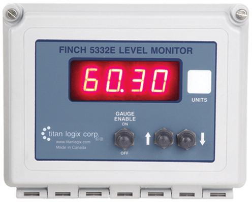
8 1.3 TD80 System Introduction and Description About the TD80 System The TD80 Level Transmitter is the heart of the TD80 level measurement system. The TD80 transmitter uses Guided Wave RADAR (GWR) to measure liquid level in a tank. It does not use any moving parts for level measurement. Guided Wave RADAR is a contacting level measurement method that uses a probe as a wave guide to channel the radio frequency energy to the liquid being measured. The probe provides an efficient path for the transmitted energy and pulse reflections from the surface of the liquid. The TD80 transmitter measures the time delay between transmitted and reflected pulses to calculate distance to the material s surface. This distance is then used to determine level of the liquid in the tank. The calculated level is converted into common volume units and is sent to a Display such as the Finch 5332 Display. The display is also part of an optional secondary overfill prevention system. TD80 generated alarms provide the approaching overfill information to halt loading at industry standard optic controlled loading racks, on-board loading pumps or valves. The TD80 system consists of a TD80 transmitter, dual rod or coaxial probe and a Finch Display. Optional components such as the Finch Relay Module, horns and lights are installed as required TD80 System Components TD80 Transmitter The TD80 transmitter generates and processes the GWR signals to determine liquid level in a tank. The TD80 is mounted on the tank top and connected to the probe, is weatherproof and rated for use in hazardous locations where explosive fumes may be present. TD80s are available in two versions, dual rod or coaxial probe for compatibility with a wide range of liquids. Probe The probe guides the transmitted pulse and reflection from the surface of the liquid. Probes are available in dual rod or coaxial versions and require a matching transmitter type. The probe is mounted on the tank top and is connected to the bottom of the transmitter. Dual rod probes are designed for viscous liquids. Coaxial probes are used mostly for tanks containing products like aviation fuel. Finch 5332 Display Finch Displays are available in weather-proof external versions, the Finch 5332E and a smaller internal version, the Finch Both provide bright LED numeric display of volume information, alarms and system error codes from the TD80 transmitter. Various alarm and error conditions are detected by the transmitter and display. These alarm states control three internal relays for alarm annunciation, overfill and low level prevention. Page 6/ TD80 Introduction/ Rev. 0.1, January 17, 2013
9 1.3.3 Optional Components P2000 The P2000 is an accessory that enables secondary overfill prevention when used with industry standard optic loading rack controllers. MIC 10 The MIC 10 is an interface device for connecting multiple TD80s to a third party modem. Finch Relay Module The Finch Relay Module is an accessory that enables overfill prevention by control of an onboard pump or loading valve. Horns and Lights Alarm reporting is through optional vehicle mounted horns and lights Theory of Operation Overview The TD80 system consists of a TD80 transmitter, dual rod or coaxial probe and an internal or external Finch Display. Optional components such as horns and lights are installed as required. The TD80 continuously measures liquid level in the tank and transmits volume information with alarm states to the Finch Display. This information is presented on a large 4 digit display and to alarm controlled relays. Alarms and errors control three separate relays to signal or control external devices. These relays indicate Spill, High-High (HH) and system Fail alarms to external devices such as overfill prevention valves, lights, horns and stationary loading controls. The HH, Spill and system Fail alarms provide information to the P2000 or Finch Relay Module and only permits loading while all conditions are safe. HH is normally the first shutdown level; Spill is a backup level slightly higher than HH, while Fail indicates failure of the TD80 system. Activation of any alarm halts loading to prevent a dangerous overfill condition or spill at the loading rack. TD80 Transmitter and Probe The TD80 transmits a continuous stream of radio frequency pulses into the probe. These pulses travel along the probe and part of the pulse energy is reflected back to the transmitter when encountering the surface of the liquid in a tank. Time delay between the transmit pulse and reflected pulse is used to calculate the distance from the tank top mounted transmitter to the liquid level. Rev. 0.1, January 17, 2013/ TD80 Introduction/ Page 7
10 The TD80 contains a table describing the tank depth and volumetric characteristics. This table is programmed before installation and operation on the tank. Liquid level is calculated from the table using maximum depth of the tank and distance from the top to the liquid surface. The TD80 sees the depth of air space in the tank and calculates the loaded volume. Physical limitations of GWR create a dead band at the bottom of the probe where the transmitted pulse interferes with the reflected echo. This region of dead band is considered to be the bottom 5.5 of the tank. Any liquid level measured at 5.5 or less is indicated by the Finch as 2 LO, meaning too low. An upper dead band exists at 7.5 from the top on the dual rod and 2.5 on the coaxial probe. Level measurements within the dead bands are inaccurate and unreliable. Calculated volume is transmitted to a Finch Display by SV Bus while a linearly scaled level is sent by the optional 4-20mA interface. The Finch is able to display up to 4 numeric digits, including a decimal point. This numeric display correctly indicates volume of loaded product in the tank. The 4-20mA output is scaled linearly for a volume of 0% at an output of 4mA and 100% volume at 20mA. SV Bus SV Bus is a single wire serial digital communication interface with an error checking protocol that eliminates false communication between the TD80 transmitter and Finch Display. SV Bus is one of the three wires required for TD80 operation with the Finch. The other two wires are power and ground. This bus is designed for reliable communications in stationary and transport environments. Finch Display The Finch Display receives a continuous stream of volume information and alarm states from the TD80 on the SV Bus. Volume, alarm states and errors are shown on the 4 digit numeric display. An additional alarm is controlled directly by the Finch. Alarms and errors control three separate relays to signal or operate external devices. TD80 controlled relays indicate Spill, High-High and system Fail alarms to external devices such as overfill prevention valves, lights, horns and stationary loading controls. The Finch controlled alarm and relay indicates a preset, increasing Fill or decreasing Fall level to warn of an approaching operator action while loading or unloading product. The Fill/Fall and High-High Alarms remain active until acknowledged by the operator. The Spill alarm remains active until the spill condition is cleared by unloading product below the spill alarm level while the system is powered and monitoring the changing level. Alarms are acknowledged by button presses on the Finch or a push button connected to the Alarm Acknowledge input. TD80 reported errors or malfunctions are indicated by the Finch showing E xx, where xx is an error code and activating the Fail alarm. Finch reported loss of communication with the TD80 is indicated by showing ---- and activating the Fail alarm. Page 8/ TD80 Introduction/ Rev. 0.1, January 17, 2013
11 Relay Module A Finch Relay Module is available to combine the Finch Spill/Fail and High- High alarm relays with a signal from the vehicle mounted Power Take-Off (PTO) to safely control an onboard overfill prevention system. The Relay Module contains high current relays to energize a bottom loading valve or hydraulic motor bypass valve for loading control. It also contains a terminal strip for power and alarm accessory interconnections. P2000 The P2000 is an accessory that enables secondary overfill prevention when used with industry standard optic loading rack controllers. The Finch controlled alarms provide an intrinsically safe signal to the P2000 that permits or denies loading at the rack. The loading rack connections are made through a standard 7-pin or 10-pin optic socket. MIC 10 The MIC 10 is an interface device for connecting multiple TD80s to a third party modem. Level, alarm and error information from the TD80s is collected by the MIC 10 and forwarded to the modem. The modem is then able to wirelessly transmit data to the back office for asset management and tracking purposes. It can be set to automatically transmit TD80 data at intervals based on a user preferred configuration, or else can send data on command from the modem. The MIC 10 features a PTO signal input to enable data transmission only when the PTO is engaged. This limits the data bandwidth required by a wireless modem The TD80 Alarm System This description refers to TD80 transmitters and Finch 5332E/PS Display (Red Terminal Board version). See notes in parentheses for the Finch 5332E Display (Green Terminal Board version). Internal Finch 5332 description is the same as the 5332E version. Internal Displays are connected by a pigtail with labeled wires instead of a terminal board as in the external Finch versions. The TD80 alarms are listed below. A vehicle mounted Power Take Off (PTO) unit may signal a loading or unloading event when alarms are required to be activated. A Display Enable (PTO) (or Gauge Enable (PTO) on 5332E Displays) signal to the Finch Display enables these alarms. An inactive PTO signal holds all alarms in the non-alarming state to prevent false triggering due to sloshing while driving. This PTO signal is usually a dry contact switch closed by the mechanical engagement of the PTO. Rev. 0.1, January 17, 2013/ TD80 Introduction/ Page 9
12 Fill/Fall Alarm Fill and Fall alarms share one relay output. The alarm is configured as a Fill or a Fall alarm with Finch Display jumper J9. The alarm point is settable by the operator. The Fill alarm is typically used to warn the operator when the loading process is nearing maximum capacity. The Fall alarm is usually used when unloading and a minimum volume of product must be retained in the tank to prevent pump damage. Fill or Fall operation is determined when the system is installed and is configured inside the Finch Display. The Finch Display is the source of this alarm. Fill/Fall alarms are indicated by the flashing the current level on the display and activating the Fill/Fall alarm relay. High-High (HH) Alarm The High-High alarm is set during transmitter programming and is normally the maximum safe volume of the tank. Dual Rod TD80 transmitters and probes are settable to a volume from 8 below the tank top and lower while the Coaxial TD80 transmitters and probes are able to be set from 3 and lower. The TD80 transmitter is the source of this alarm. The HH alarm is activated by a measured volume equal to or exceeding the alarm level set during programming. High-High alarms are indicated by alternately flashing HH along with the current level on the Display and activating the HH alarm relay. Spill Alarm Spill is an approaching overfill condition. Dual Rod TD80 transmitters and probes are factory set at 7.5 below the tank top while Coaxial TD80 transmitters and probes are selectable in the range of 2.5 down to 15.5 from the top. The TD80 transmitter is the source of this alarm. Spill alarms are indicated by showing SPill on the display and activating the spill alarm through the Spill/Fail (or Fail on the 5332E Displays) relay. Fail Alarm System failures such as internal transmitter errors, probe faults or loss of communications are reported by the Spill/Fail (or Fail on the 5332E Displays) relay. The Finch Display reports communication failure. The TD80 transmitter is the source for all other system errors. Errors are displayed as E xx, where xx is an error code. Loss of communication between the TD80 and Finch is displayed as Alarm Relays 1. Fill/Fall relay 2. High-High relay 3. Spill/Fail (or Fail on 5332E Displays) relay. Page 10/ TD80 Introduction/ Rev. 0.1, January 17, 2013
13 Devices such as horns and lights are connected to these alarm relays for operator action. The Fall, High-High and Spill/Fail relays typically operate shutdown controls including external relays, and solenoid operated valves. 1.4 Overfill Prevention System Description The description below incorporates the recommended Finch Relay Module. See the Overfill Prevention System Installation Section 2.7 for detail. 1. Power On The TD80 and Finch proceed through the normal start-up sequence as described below. Once completed; OFF will be displayed on the Finch. Level is displayed for 30 seconds by a momentary press of the Up or Down buttons. 2. PTO Engaged The operator engages the truck mounted PTO to begin loading. The PTO signal to the Finch is controlled by an air/electric switch that causes the following to occur: 1. Finch Display to an active mode with all alarms enabled and continuous level display. 2. A Solenoid is energized to allow loading by controlling a Normally Closed bottom loading valve or a Normally Open hydraulic motor bypass valve. 3. The Green Light is on to indicate loading is permitted. 4. The Red Light and Horn are off at the start of the loading process. Bottom Loading Valves: The unpowered condition of a bottom loading valve is normally closed. The solenoid must be powered to allow loading. Any alarm condition for system errors, failures or overfill will cause the solenoid to be de-energized and halt the loading process. A disengaged PTO will also close the valve. Hydraulic Bypass Valves. The unpowered condition for a hydraulic motor bypass valve is normally open. The solenoid must be powered to allow loading by closing the bypass circuit. Any alarm condition for system errors, failures or overfill will cause the solenoid to de-energize and halt the loading process. A disengaged PTO will also open the valve. 3. Operator fills the tank The liquid is loaded into the tank using either the on-board or a stationary pump. When the liquid reaches the Fill alarm level, the following occurs: a. The Red light and Horn turn on to alert the operator that he is getting close to the loading limit and has to prepare to turn off the pump and close the valve. b. The Green Light stays on to indicate continued loading is permitted. Rev. 0.1, January 17, 2013/ TD80 Introduction/ Page 11
14 c. The Solenoid continues to be energized to allow loading. d. The Finch Display flashes the level indication to indicate the active Fill alarm. The operator then presses either the Up or Down button on the Finch to silence the horn, turn off the Red light and return to a normal level display. The operator continues to load. He will likely manually shut off the pump and close the valve before the liquid level reaches the HH alarm level. If he does not and the liquid level reaches the HH alarm level, then the following occurs: a. Green light turns off b. The solenoid de-energizes, closing the bottom loading valve or opening the on-board pump bypass valve. This halts the loading process. If the tank has been loaded to the required amount, then the operator turns off the pump, closes the valve, disconnects the hoses and drives away. If the tank has not been loaded to the required amount, then the operator clears the HH alarm on the Finch with the UP/UP/DOWN/UP button sequence. This resets the alarm response and allows further loading with the following: a. The Green Light turns back on b. The Solenoid is re-energized c. The Solenoid either opens the bottom loading valve or closes the onboard pump bypass valve to allow loading to continue. The operator is likely to stop loading before the level reaches the Spill alarm level. If the operator continues to load and reaches the Spill alarm level, the following occurs: a. Green Light turns off b. The Solenoid is de-energized c. The de-energized solenoid either closes the bottom loading valve or opens the on-board pump bypass valve to halt the loading process. The operator cannot reset or acknowledge the Spill alarm. The liquid must be pumped out of the tank until it drops several inches below the HH alarm level. The Spill alarm then clears and enables loading through a bottom 4. PTO Disengaged When the operator has completed the loading procedure, he turns off the PTO. This deactivates the Finch alarms, displays OFF and prevents the solenoid from energizing to disable loading through a bottom loading valve or a bypass valve on a hydraulic motor. He now drives to a new location to load or unload. Page 12/ TD80 Introduction/ Rev. 0.1, January 17, 2013
15 5. Sequence of Events with Finch Relay Module installed Event Sequence Truck started, PTO NOT engaged Finch Display OFF Red Light, Horn Pulsed, then OFF Green Light OFF Solenoid OFF PTO engaged 2 LO or OFF ON ON Level Liquid loaded to Fill level Flashing ON ON ON Level Operator presses UP or DOWN Level OFF ON ON button Liquid loaded to HH alarm level HH /Level OFF OFF OFF Operator presses Level OFF ON ON UP/UP/DOWN/UP Liquid loaded to Spill level SPILL OFF OFF OFF PTO is disengaged. Operator OFF OFF OFF OFF drives to next site. Operator pumps out liquid with Level OFF ON ON PTO engaged. All liquid is pumped out 2 LO OFF ON ON PTO is disengaged. Operator drives to next site OFF OFF OFF OFF Table 1-1: Sequence of Events with Finch Relay Module installed Rev. 0.1, January 17, 2013/ TD80 Introduction/ Page 13
16 1.5 Graphical Glossary of Terms Dual Rod Probe Truck and Trailer Installation Figure 1-1: Dual Rod Probe Truck & Trailer Installation Page 14/ TD80 Introduction/ Rev. 0.1, January 17, 2013
17 Coaxial Probe Truck and Trailer Installation Figure 1-2: Coaxial Probe Truck & Trailer Installation Rev. 0.1, January 17, 2013/ TD80 Introduction/ Page 15


18 TD80 Programming SV PROGRAMMING KIT Figure 1-3: SV Programming Kit PC PROGRAMMING SOFTWARE, BIRDFEEDER 2 Figure 1-4: PC Programming Software Birdfeeder 2 Page 16/ TD80 Introduction/ Rev. 0.1, January 17, 2013
19
20 Manufactured in Canada Manufactured by: Head Office Street Edmonton, Alberta Canada T6E 5P5 P F Saskatchewan Branch Box Cenaiko Street Lampman, Saskatchewan Canada S0C 1N0 P F Kansas Branch 8900 Nieman Road Overland Park, Kansas USA P F Toll Free TSX-V: TLA Sales Department: us at sales@titanlogix.com Service Department: us at service@titanlogix.com Find us online at
TD80 LEVEL GAUGING & OVERFILL PREVENTION SYSTEM PRODUCT MANUAL SUPPLEMENT. TPM 005 Revision 0.0
 TD80 LEVEL GAUGING & OVERFILL PREVENTION SYSTEM PRODUCT MANUAL SUPPLEMENT TPM 005 Revision 0.0 Table of Contents 1 TD80 Current Loop Option... 2 1.1 Introduction... 2 1.2 Components... 2 1.3 Operation...
TD80 LEVEL GAUGING & OVERFILL PREVENTION SYSTEM PRODUCT MANUAL. TPM 001 Revision 0.1
 TD80 LEVEL GAUGING & OVERFILL PREVENTION SYSTEM PRODUCT MANUAL Revision 0.1 2 TD80 Installation 2.1 TD80 Installation Steps Overview 2.1.1 Pre-Installation Requirements 1. When choosing a location to
SPILLSTOP ULTRA Alarm Controller with Hose Protection Overfill Prevention System
 SPILLSTOP ULTRA Alarm Controller with Hose Protection Overfill Prevention System TM MODEL 815-UDHP/H HYDRAULIC VERSION MANUAL Printed in Canada www.garnetinstruments.com GARNET SPILLSTOP ULTRA TM Hose
SPILLSTOP ULTRA Hose Protection Overfill Prevention System
 SPILLSTOP ULTRA Hose Protection Overfill Prevention System TM MODEL 815-UHP/H HYDRAULIC VERSION MANUAL Printed in Canada INSTRUMENTS LTD. Page 1 GARNET SPILLSTOP ULTRA TM Hose Protection Overfill Prevention
NORTH HARRIS COUNTY REGIONAL WATER AUTHORITY. Section CHLORINE GAS LEAK DETECTOR
 Section 11263 PART 1 GENERAL 1.01 SUMMARY This Section includes the furnishing and installation of chlorine leak detectors as shown on Plans and specified herein. 1.02 MEASUREMENT AND PAYMENT No separate
AUTOMATION. Operator s Manual RST Series Web Enabled Input Module. Rev. A2, 1/12
 AUTOMATION P R O D U C T S GROUP, INC. Operator s Manual RST-5000 Series Web Enabled Input Module Rev. A2, 1/12 Tel: 1/888/525-7300 Fax: 1/435/753-7490 www.apgsensors.com E-mail: sales@apgsensors.com RST-5000
! "! # Please read these installation and operating instructions completely and carefully before starting.
 ! "! # $% Please read these installation and operating instructions completely and carefully before starting. File name:3009405d Revised,20/10/2008 Copyright, July 2004 The Armstrong Monitoring Corporation
Instruction manual MTL process alarm equipment. October 2016 CSM 725B rev 2 MTL RTK 725B. Configuration Software Manual
 Instruction manual MTL process alarm equipment October 2016 CSM 725B rev 2 MTL RTK 725B Configuration Software Manual SECTION 1 - INTRODUCTION... 5 Basic Requirements... 5 SECTION 2 - SOFTWARE INSTALLATION...
SCAN200E USER S MANUAL
 SCAN200E USER S MANUAL Code No. 2071 1052 rev. 1.4 Code No. 2071 1052 Rev. 1.4 Page 2/16 SCAN200E User s Manual Foreword This manual is for SCAN200E Controller running software version 2.03 or later. We
1022 R/T Remote Monitor
 1022 R/T Remote Monitor INSTRUCTIONS AMC-1022R/T WITH REMOTE SENSOR OR TRANSMITTER INSTALLATION AND OPERATING INSTRUCTIONS FOR THE AMC-1022R/T UNIT IMPORTANT: Please read these installation and operating
Model Gas Alarm Panel APPLICABILITY & EFFECTIVITY. This manual provides instructions for the following Sierra Monitor products:
 Model 2102 Gas Alarm Panel APPLICABILITY & EFFECTIVITY This manual provides instructions for the following Sierra Monitor products: Model Description 2102-00 Alarm Panel 2 Channel 2102-01 Alarm Panel 2
1228s Multidrop INSTRUCTIONS. Installation and Operation of the AMC-1228s Electrochemical Sensor Module For Use With Multidrop AMC Monitors
 228s Multidrop INSTRUCTIONS Installation and Operation of the AMC-228s Electrochemical Sensor Module For Use With Multidrop AMC Monitors IMPORTANT: Please read these installation and operating instructions
RAM3 Remote Alarm Module
 RAM3 Remote Alarm Module INSTRUCTIONS Installation and Operation of the AMC-RAM3 with AMC Monitors IMPORTANT: Please read this installation and operating instructions completely and carefully before starting.
G34 AU1B (External Ultrasonic Sensor) Version 3
 Version 3") Car Alarm Series 3 B 4 Buttons G34 AU1B (External Ultrasonic Sensor) Version 3 24 CAR ALARM GENIUS Series 3B 4 Buttons G34 AU1B (External Ultrasonic Sensor) Module controlled using Micro-Processor 2 Transmitters
Car Alarm Series 3 B 4 Buttons G34 AU1B (External Ultrasonic Sensor) Version 3 24 CAR ALARM GENIUS Series 3B 4 Buttons G34 AU1B (External Ultrasonic Sensor) Module controlled using Micro-Processor 2 Transmitters
SERIES 101T MOISTURE ANALYZER QUICK START GUIDE
 SERIES 101T MOISTURE ANALYZER QUICK START GUIDE INSTALLATION The moisture probe may be installed directly into the sample stream through a ½ inch NPT adapter (See Fig. 1). The penetration into the sample
Sentry LIQUID LEVEL ALARM MODEL 100 OPERATING MANUAL.
 Sentry LIQUID LEVEL ALARM MODEL 100 OPERATING MANUAL www.aquaticsentry.com TABLE OF CONTENTS 1. SAFETY PRECAUTIONS... 3 2. APPLICATION... 3 2.1 HIGH Liquid Level Alarm 2.2 LOW Liquid Level Alarm 3. INSTALLATION...
Design Manual Installation Operation Maintenance
 Design Manual Installation Operation Maintenance Model FT194 UV/IR Portable Flame Detector Test Lamp 23282 Mill Creek Drive, Suite 215 Laguna Hills, CA 92653 USA +1.949.583.1857 Phone +1.949.340.3343 Fax
STATUS ALARM ALARM HISTORY POWER HISTORY RESET
 Instruction Manual Model 1582-70L2 RF Switch June 2011, Rev. D CH1 AUTO CH2 SWITCH 1 2 1 2 STATUS 1 2 MODEL 1582 SWITCH CROSS TECHNOLOGIES INC. CH1 ONLINE MANUAL SELECT CH2 SWITCH MANUAL REMOTE ONLINE
Sentry LIQUID LEVEL CONTROLLER MODEL 120 OPERATING MANUAL.
 Sentry LIQUID LEVEL CONTROLLER MODEL 120 OPERATING MANUAL www.aquaticsentry.com TABLE OF CONTENTS 1. SAFETY PRECAUTIONS... 3 2. APPLICATION... 3 2.1 HIGH AND LOW LEVEL ALARM 2.2 PUMP DOWN CONTROLLER 2.3
Pipo Communications. Model ST-888. DTMF ANI/ENI Display Decoder
 Pipo Communications Model ST-888 DTMF ANI/ENI Display Decoder 1516 Cassil Place Hollywood, California 90028-7106 Phone: 323-466-5444 Fax: 323-466-1520 www.pipo.cc Manual # 68-9888 May 1, 2002 Rev. 5/02
1 4 DIN Dissolved Oxygen Controller
 16. Warranty OAKTON warrants this controller to be free from significant deviations in material and workmanship for a period of one year from date of purchase. If repair or adjustment is necessary and
User s Manual and Warranty Information for Counterweighted Chain Drive ThyssenKrupp Access
 II User s Manual and Warranty Information for Counterweighted Chain Drive ThyssenKrupp Access Part #2139703 Rev. G II Table of Contents Introduction...3 Elevator Overview...4 Description of Features...5-7
Continuous, real-time detection, alarming and analysis of partial discharge events
 DMS PDMG-R Partial discharge monitor for EHV GIS Continuous, real-time detection, alarming and analysis of partial discharge events Automatic PD fault classification Robust design allows for reliable operation
Meridian wiredhart. HART Field Device Specification Goldmine Rd. Monroe, NC USA
 HART Field Device Specification Meridian wiredhart 4320 Goldmine Rd. Monroe, NC 28110 USA HART is a registered trademark of the HART Communication Foundation TABLE OF CONTENTS 1. Introduction...5 1.1 Scope...5
Dough Retarder Prover. Service Manual
 Service Manual Revision 3 June 2000 Dough Retarder Prover - Service Manual RBC MKII Controller Revision 6 Page 2 CONTENTS Page(s) 1. INTRODUCTION 3 2. RBC MK 2 CONTROLLER OPERATION 5-9 Process Cycle Overview
Control Panel. 1.0 GENERAL SCOPE OF WORK Introduction... 2
 Architectural & Engineering Specifications Control Panel 1.0 GENERAL... 2 1.1 SCOPE OF WORK... 2 1.1.1 Introduction... 2 1.2 GENERAL CONDITIONS... 2 1.2.1 After-Sales Support... 2 1.2.2 Quality assurance...
3820, 3820i, 4820, 4820i
 3820, 3820i, 4820, 4820i Cordless Imaging Systems Quick Start Guide Note: Refer to your user s guide for information about cleaning your device. For localized language versions of this document, go to
Ion Endeavor Pump Controller Digital Level Control with Pump Alternation and High Water Alarm
 Ion Endeavor Controller Digital Level Control with Alternation Page 1 of 8 General Overview The Ion Endeavor is a pump controller that senses a water level of up to 72", has a configurable water level/pump
AMC-RAM-4. Refrigerant Alarm Module USER MANUAL. Please read the installation and operating instructions completely and carefully before starting.
 AMC-RAM-4 Refrigerant Alarm Module USER MANUAL IMPORTANT: Please read the installation and operating instructions completely and carefully before starting. Filename: 3310405B, DOC, AMC_RAM4_Manual.doc
F PC and AO OUTPUT BOARDS INSTRUCTION MANUAL. Blue-White. Industries, Ltd.
 F-2000 PC and AO OUTPUT BOARDS INSTRUCTION MANUAL Blue-White R Industries, Ltd. 500 Business Drive Huntington Beach, CA 92649 USA Phone: 714-89-8529 FAX: 714-894-9492 E mail: sales@blue-white.com or techsupport@blue-white.com
Beacon 800 Gas Monitor Operator s Manual
 Beacon 800 Gas Monitor Operator s Manual Part Number: 71-0037RK Revision: F Released: 4/18/17 www.rkiinstruments.com Product Warranty RKI Instruments, Inc. warrants gas alarm equipment sold by us to be
Pump-Down Controller MODEL 4052
 Pump-Down Controller 4-20mA Input/Scalable Output Seal Fail Monitoring Duplex Pump Alternation Hand-Off-Auto Controls Dual Run-time Meters RS-485/Modbus Communications DESCRIPTION The Model 4052 Pump-Down
Refer to Bulletin E-1101 for detailed information on the FLAME-MONITOR System.
 The Fireye EP260, EP270 (early spark termination), or EP265 (pilot stabilization) programmer modules are used with the FLAME-MONITOR Burner Management Control System (P/N E110). Several operational characteristics
GTA 4100R. Dual Processor, Dual Channel Controller Card. Part Number R. Manual Revision v6.30 (updated 10 November 2009)
") GTA 4100R Dual Processor, Dual Channel Controller Card Part Number 73 4100R Manual Revision v6.30 (updated 10 November 2009) Table of Contents 1 Introduction...6 1.1 Features...6 1.2 Front Panel Layout...7
GTA 4100R Dual Processor, Dual Channel Controller Card Part Number 73 4100R Manual Revision v6.30 (updated 10 November 2009) Table of Contents 1 Introduction...6 1.1 Features...6 1.2 Front Panel Layout...7
User s Manual. TIGER S EYE E-Series Mark V Jockey. TIGERFLOW Systems, Inc Mint Way Dallas, Texas
 User s Manual TIGER S EYE E-Series Mark V Jockey TIGERFLOW Systems, Inc. 4034 Mint Way Dallas, Texas 75237 214-337-8780 www.tigerflow.com TABLE OF CONTENTS Introduction... 4 Sequence of Operation... 5
Modbus TCP/IP Option Instruction Manual
 W A L C H E M An Iwaki America Company WebMaster Modbus TCP/IP Option Web Master WIND Modbus TCP/IP Option Instruction Manual s825v008 and higher Five Boynton Road Hopping Brook Park Holliston, MA 01746
MODEL 5100 VOTING LOGIC MODULE
 DESCRIPTION DESCRIPTION The SST Model 5100 Multi-Input Voting Logic Module is used to monitor the status of up to 14 different points in a hazard zone, and report when a selectable number of these points
Pump-Up Controller MODEL 4062
 Pump-Up Controller 4-20mA Input/Scalable Output Seal Fail Monitoring Duplex Pump Alternation Hand-Off-Auto Controls Dual Run-time Meters RS-485/Modbus Communications DESCRIPTION The Model 4062 Pump-Up
Falcon-II Next Generation, Air Quality Monitor CO2 & Temperature
 Critical Environment Technologies Canada Inc. Falcon-II Next Generation, Air Quality Monitor CO2 & Temperature OPERATION MANUAL REV: A JUNE-2-2008 #145, 7391 Vantage Way Delta, BC V4G 1M3 Canada Phone:
Integrated Security Solutions
 Integrated Security Solutions Table of Contents Control Panels 4 Keypads 8 Communication Modules 16 I/O Expanders 20 Door Control 24 Home Automation 25 RF Receivers 26 3 Our integrated security solutions
GSM RFID VOICE Alarm System
 GSM RFID VOICE Alarm System User s Manual For a better understanding of this product, please read this user manual thoroughly before using it. CONTENTS [Function Instruction] [Control Panel] Control Panel
Installation Manual Version 1.3. Long Range RF Transmitter. How to contact us:
 How to contact us: Technical Support If you have questions or problems when using this product, you can call Technical Support. If you are within the United States or Canada, you can get support by dialing
Long Range Radio Alarm Transmitter
 TM Long Range Radio Alarm Transmitter INSTALLATION MANUAL Version 1.3W FEATURES Transmits alarm information to a long range radio network Varitech Transmission Format Note: If automatic SIA is used in
GasScanner 8C. Eight Channel Monitor. Operator s Manual. MINT-0281-XX Rev. A 01/29/08
 GasScanner 8C Eight Channel Monitor Operator s Manual MINT-0281-XX Rev. A 01/29/08 Product Warranty Matheson Tri-Gas, Inc., warrants gas alarm equipment sold by us to be free from defects in materials,
Model 4001 Series Single Channel Controller
 Model 4001 Series Single Channel Controller Sierra Monitor Corporation 1991 Tarob Court, Milpitas, CA 95035 (408) 262-6611 (800) 727-4377 (408) 262-9042 - Fax E-Mail: sales@sierramonitor.com Web site:
Simplex Panel Interface Guide
 Simplex Panel Interface Guide February 2016 SATEON Software Integrations Simplex Panel Interface Guide Issue 1.0, released February 2016 Disclaimer Copyright 2016, Grosvenor Technology. All rights reserved.
STATUS ALARM HISTORY ALARM RESET
 Instruction Manual Model 1582-42L Data Switch February 1999, Rev 0 CH1 AUTO CH2 SWITCH 1 2 1 2 STATUS 1 2 MODEL 1582 SWITCH CROSS TECHNOLOGIES INC. CH1 ONLINE MANUAL SELECT CH2 ONLINE SWITCH RESET MAN
Ion Genesis II Pump Controller Digital Level Control with Pump Alternation and High Water Alarm
 Page 1 of 8 General Overview Thank you for purchasing an Ion Genesis controller. Take the time to read the instructions carefully before using this appliance. We strongly recommend that you keep this instruction
OPERATION MANUAL MODEL LC2000 COPYRIGHT 2017 PNEUMERCATOR CO., INC EXPRESSWAY DRIVE NORTH HAUPPAUGE, NY 11788
 PNEUMERCATOR Liquid Level Control Systems LEAK/POINT LEVEL ALARM CONSOLE OPERATION MANUAL DRAWING NO. 20068 REV. N/C MODEL COPYRIGHT 2017 PNEUMERCATOR CO., INC. 1785 EXPRESSWAY DRIVE NORTH HAUPPAUGE, NY
Table of Contents. Digital Hazard Monitoring Revision Notes 2. Digital Hazard Monitoring Safety Warning 3
 Table of Contents Digital Hazard Monitoring Revision Notes 2 Digital Hazard Monitoring Safety Warning 3 Digital Hazard Monitoring System Component Overview 4 Digital Hazard Monitoring Screen Overview 5
Installation and Operating Instructions
 The Leader of RF and Sonic Level For Assistance Call 1-800-527-6297 Outside North America 1-215-674-1234 Installation and Operating Instructions Series 504-1200 Ultrasonic VeriGAP Switch using 404-1200
M3050 Detector Operator s Manual
 FABRICON SYSTEMS ALBERTA 2008 INC. Keeping you in Front M3050 Detector Operator s Manual Telephone: (403)652-2127 Mailing Address: Shipping Address: Fax: (403)652-3027 Box 5996 402 Ellis Crescent S.E Email:
Duct Mount. Installation Instructions
 Duct Mount Installation Instructions 00809-0600-4975 Legal Notice The Flame Detector described in this document is the property of Rosemount. No part of the hardware, software, or documentation may be
ACCURATE ELECTRONICS INC PO BOX SW HALL BLVD BEAVERTON OR USA FAX
 Page 1 of 10 Model 10807800 January 2014 ACCURATE ELECTRONICS INC PO BOX 1654 97075-1654 8687 SW HALL BLVD 97008 BEAVERTON OR USA 503.641.0118 FAX 503.646.3903 WWW.ACCURATE.ORG Practice Section 10807800
Figure 1. Proper Method of Holding the ToolStick. Figure 2. Improper Method of Holding the ToolStick
 CAN OBD READER REFERENCE DESIGN KIT USER GUIDE 1. Standard ToolStick Handling Recommendations The ToolStick Base Adapter and daughter cards are distributed without any protective plastics. To prevent damage
LineGuard 2300 Program User Manual (FloBoss 107)
") Form A6251 Part Number D301346X012 November 2012 LineGuard 2300 Program User Manual (FloBoss 107) Remote Automation Solutions Revision Tracking Sheet November 2012 This manual may be revised periodically
Form A6251 Part Number D301346X012 November 2012 LineGuard 2300 Program User Manual (FloBoss 107) Remote Automation Solutions Revision Tracking Sheet November 2012 This manual may be revised periodically
SmartLINK Module Ei3000MRF for Mains Powered Multi-Sensor Fire / Smoke / Heat / CO Alarms - Ei3000 Series
 SmartLINK Module Ei3000MRF for Mains Powered Multi-Sensor Fire / Smoke / Heat / CO Alarms - Ei3000 Series Instruction Manual Read and retain carefully for as long as the product is being used. It contains
Honeywell Control Panels FOR RESIDENTIAL AND COMMERCIAL INSTALLATIONS. Feature Charts
 Honeywell Control Panels FOR RESIDENTIAL AND COMMERCIAL INSTALLATIONS Feature Charts Control Panels FEATURE CHART LYNX Plus (L3000) (Supported Feature) (Not Supported) N/A (Not Applicable) LYNX Touch (L5210)
FI6000 INSTRUCTION MANUAL. Thank you for choosing another quality product from Amperes Electronics. Fire Alarm Interface
 INSTRUCTION MANUAL FI6000 Fire Alarm Interface Thank you for choosing another quality product from Amperes Electronics. FI6000 is a phase evacuation controller which can be integrated with various Amperes
ProTalk. Expander. Operating Manual Model B1292. July 28, 2009 Rev. 1.01
 ProTalk Expander Operating Manual Model B1292 July 28, 2009 Rev. 1.01 TABLE OF CONTENTS 1. Introduction... 1 2. Installation... 2 2.1 Wiring Diagram... 3 3. Operations... 4 4. Programming (B1225 Mode)...
Users Manual. LAURUS Systems, Inc. - Ph: Fax:
 Users Manual LAURUS Systems, Inc. - Ph: 410-465-5558 - Fax: 410-465-5257 - www.laurussystems.com Introduction The rad-d is a security and inspection system that detects emissions from radioactive material.
CPS-1 USER S MANUAL AIR INLET / CURTAIN CONTROL
 CPS-1 USER S MANUAL AIR INLET / CURTAIN CONTROL temperature / static pressure DIFF Opn Clo ALARM HI F2 DELAY ALARM LO OPEN DELAY CLOSE ADJUST Varifan + CPS-1 CPS-1 Although the manufacturer has made every
Beam Sensor 100 Mtr Manual Wired Type & Convertible to Wireless Type Model: BS- Series Outdoor Use
 Contents Features Description 100 Mtr Manual Wired Type & Convertible to Wireless Type Model: BS- Series Outdoor Use We extend a warm welcome to you on becoming a part of the Copper Connections family
Controllers. Instruction Manual WARNING
 Controllers Instruction Manual WARNING THIS MANUAL MUST BE CAREFULLY READ BY ALL INDIVIDUALS WHO HAVE OR WILL HAVE THE RESPONSIBILITY FOR INSTALLING, USING OR SERVICING THIS PRODUCT. Like any piece of
AlertMaxx2. Installation & Operating Manual. Ground Water (DMS-298) Pump Station High Level Alarm
 Pump Station High Level Alarm") Ground Water (DMS-298) Installation & Operating Manual Pump Station High Level Alarm T. E. W. 01992 523 523 info@deltamembranes.com www.deltamembranes.com Delta House, Merlin Way, North Weald, Epping,
Ground Water (DMS-298) Installation & Operating Manual Pump Station High Level Alarm T. E. W. 01992 523 523 info@deltamembranes.com www.deltamembranes.com Delta House, Merlin Way, North Weald, Epping,
Three Phase Simplex. Installation (937) Installation Instructions and Operation/Troubleshooting Manual. Installation of Floats.
 Installation Instructions and Operation/Troubleshooting Manual. Installation of Floats.") Three Phase Simplex Installation Instructions and Operation/Troubleshooting Manual This control panel must be installed and serviced by a licensed electrician in accordance with the National Electric Code
Three Phase Simplex Installation Instructions and Operation/Troubleshooting Manual This control panel must be installed and serviced by a licensed electrician in accordance with the National Electric Code
Maintenance Manual PC6010. WARNING This manual contains information on limitations regarding product use and function
 WARNING This manual contains information on limitations regarding product use and function and information on the limitations as to liability of the manufacturer. The entire manual should be carefully
INSTRUCTION MANUAL. Software Revision Card 3.2 DOCUMENT SES-KS E REV. 3
 2402 COMBUSTIBLE GAS CARD 2 CHANNELS 2404 TOXIC GAS CARD 2 CHANNELS 2407 OXYGEN GAS CARD 2 CHANNELS INSTRUCTION MANUAL Software Revision Card 3.2 DOCUMENT SES-KS-2402-04-07-E REV. 3 2402 2404 2407-2 CHANNELS
Instruction Manual WARNING
 Controllers Instruction Manual WARNING THIS MANAUL MUST BE CAREFULLY READ BY ALL INDIVIDUALS WHO HAVE OR WILL HAVE THE RESPONSIBILITY FOR INSTALLING, USING OR SERVICING THIS PRODUCT. Like any piece of
1040 Gas Monitor INSTALLATION AND OPERATING INSTRUCTIONS AMC-1040 WITH INTEGRAL ELECTROCHEMICAL SENSOR
 1040 Gas Monitor INSTALLATION AND OPERATING INSTRUCTIONS AMC-1040 WITH INTEGRAL ELECTROCHEMICAL SENSOR IMPORTANT: Please read these installation and operating instructions completely and carefully before
installation & operation manual
 installation & operation manual TABLE OF CONTENTS INTRODUCTION... 2 FEATURES... 2 PROGRAMMING CONTACT ID... 3 INSTALLATION... 3 OPENING THE HAWK COVER... 3 POWER SUPPLY... 5 CHECK AC... 5 DRY CONTACTS
PRO-TEC SYSTEM ONE. Trailer Security Systems Model # PTS-2. Photo includes PTS-2 with optional pager unit
 PRO-TEC SYSTEM ONE Trailer Security Systems Model # PTS-2 Photo includes PTS-2 with optional pager unit Professional Technology to Pro-Tec Your Investment More helpful install information on our website
TLS-300 UST Monitoring and Leak Detection System
 Part 1 General System Requirements 1.1 Description TLS-300 UST Monitoring and Leak Detection System A. These Specifications are intended to provide information by which prospective bidders may understand
Section PERIMETER SECURITY SYSTEMS
 Section 28 16 43 PERIMETER SECURITY SYSTEMS PART 1 GENERAL 1.1 SUMMARY A. Provide and install a perimeter security system as herein specified for the purpose of detecting entry into a designated security
600 Range Dialer Installation Manual. Version 1.0
 600 Range Dialer Installation Manual Version 1.0 The information contained is supplied without liability for any errors or omissions. No part may be reproduced or used except as authorised by contract
Instruction Manual Model Backup Switch, 1 for 8
 Instruction Manual Model 2582-282 Backup Switch, 1 for 8 December 2011, Rev. 0 MODEL 2582 SWITCH CROSS TECHNOLOGIES INC. SWITCH ALARM PSA PSB ALARM OFFLINE ONLINE UNIT STATUS 1 2 3 4 5 6 7 8 BU PROT MODE
PAC-2750 ELECTRIC COOLING FAN CONTROLLER
 PAC-2750 ELECTRIC COOLING FAN CONTROLLER IMPORTANT NOTE: The +12V for the controller should NOT be taken from the same circuit as the Fan Power 12V as this can cause the fan to cycle on and off. Required
Preliminary. SmarteLight v1.2 Manual. Revision: 1.0 Date: 12/4/2012. Revision: 1.0 Page i OmniSite
 Preliminary Revision: 1.0 Date: 12/4/2012 Revision: 1.0 Page i OmniSite Table of Contents Table of Contents... ii Revision History... iii Notice...iv Warning...iv Limited Warranty...iv Contact Information...iv
Long Range Radio Alarm Transmitter
 W A R N I N G Please refer to the System Installation Manual for information on limitations regarding product use and function and information on the limitations as to liability of the manufacturer. TM
Installation, Operation & Service Manual
 Installation, Operation & Service Manual WARNING Improper installation, adjustment, alteration, service or maintenance can result in death, injury or property damage. Read the Installation, Operation and
STATUS ALARM ALARM HISTORY POWER HISTORY RESET
 Instruction Manual Model 1582-152 RF Protection Switch November 2009, Rev B. CH1 AUTO CH2 SWITCH 1 2 1 2 STATUS 1 2 MODEL 1582 SWITCH CROSS TECHNOLOGIES INC. CH1 ONLINE MANUAL SELECT CH2 SWITCH MANUAL
Watchguard WGAP864 User Manual
 Watchguard WGAP864 User Manual v1.0 Issued September 2016 1 2 Table of Contents Glossary... 5 1. Introduction to your Watchguard WGAP864... 6 2. Before Operating your Alarm System... 6 3. Understanding
Custom Control Systems Inc. Ellis Dryer Control Configuration and Operation Manual
 Ellis Dryer Control Configuration and Operation Manual Revised 1/19/2004 Table of Contents 1 Introduction... 7 1.1 Hardware Specifications... 7 1.2 Software Features... 7 1.3 Warranty... 8 1.3.1 Terms...
Ring Detect Relays. Model RDR. Installation & Operation. Ph: \ \
 Ring Detect Relays Installation & Operation P005116 Rev. D 141020 10/20/2014 11:25 AM Ph: 403.258.3100 \ email:info@guardiantelecom.com \ www.guardiantelecom.com Table of Contents Package Contents...2
Testing the System. Battery Test. Dialer Test. Fire Drill Test (Code + [#] + 69) One-Man Fire Walk-Test (Code + [#] + 68)
![Testing the System. Battery Test. Dialer Test. Fire Drill Test (Code + [#] + 69) One-Man Fire Walk-Test (Code + [#] + 68)](/thumbs/79/79864325.jpg "Testing the System. Battery Test. Dialer Test. Fire Drill Test (Code + [#] + 69) One-Man Fire Walk-Test (Code + [#] + 68)") F A 1 7 0 0 c Testing the System Battery Test When AC power is present, the FA1700C runs a brief battery test every 60 seconds to determine if there is a battery connected, and runs an extended battery
F A 1 7 0 0 c Testing the System Battery Test When AC power is present, the FA1700C runs a brief battery test every 60 seconds to determine if there is a battery connected, and runs an extended battery
ATS1235 Advanced Wireless DGP on 868 MHz AM Installation Sheet
 ATS1235 Advanced Wireless DGP on 868 MHz AM Installation Sheet EN 1 2 1 3 2 4 1 5 12V 6 2 0V D+ D- CON3 7 CON1 ON 3 1 2 3 4 1234 8 3 4 1 0 ON 1 2 3 4 METAL METAL Address 1 1 0 ON 1 2 3 4 Address 2 2011
ACL TC 200 TEMPERATURE CONTROLLER
 TC 200 TEMPERATURE CONTROLLER TC 200 TEMPERATURE CONTROLLER WARNING This manual must be read in its entirety before installation of this controller. Installation must be performed by a qualified technician
Panel Mounted Fault Annunciator Series
 Panel Mounted Fault Annunciator Series BSM / USM Panel-mounted fault annunciator Annunciators for panel mounting with,,,, 0 and signal inputs Storage of the last state of inputs and sequence in the case
PodView Level Indicator LI40 Series Manual
 PodView Level Indicator LI40 Series Manual Flowline Inc. 10500 Humbolt Street Los Alamitos, CA 90720 Tel: (562) 598 3015 Fax: (562) 431 8507 www.flowline.com Rev A MN204260 1 of 16 INTRODUCTION / TABLE
430128A. B-Series Flow Meter SIL Safety Manual
 430128A B-Series Flow Meter SIL Safety Manual Copyrights and Trademarks Copyright 2016 Kurz Instruments, Inc. All rights reserved. No part of this publication may be reproduced or transmitted in any form
AN FXPS7xxx series pressure sensor self-test features. Document information
 Rev. 1 15 November 2018 Application te Document information Information Keywords Abstract Content self test, digital barometric absolute pressure (DBAP), absolute pressure sensor, engine management, comfort
Integrated Security Solutions
 Integrated Security Solutions Table of Contents Control Panels 4 Keypads 8 Communication Modules 16 I/O Expanders 20 Door Control 24 Home Automation 25 RF Receivers 26 2 Our integrated security solutions
RK Carbon Monoxide Transmitter Operator s Manual
 65-2432RK Carbon Monoxide Transmitter Operator s Manual Part Number: 71-0070RK Revision: P1 Released: July 8, 2001 RKI Instruments, Inc. 1855 Whipple Road Hayward CA 94544 Phone: 800-754-5165 Fax: 510-441-5650
Ambient Weather WS-091-C Three Channel Display Wireless Thermometer (Console Only) User Manual
 User Manual") Ambient Weather WS-091-C Three Channel Display Wireless Thermometer (Console Only) User Manual Table of Contents 1 Introduction... 2 2 Getting Started... 2 Parts List... 3 2.2 Display Console Set Up...
Ambient Weather WS-091-C Three Channel Display Wireless Thermometer (Console Only) User Manual Table of Contents 1 Introduction... 2 2 Getting Started... 2 Parts List... 3 2.2 Display Console Set Up...
INSTALLATION AND OPERATING INSTRUCTIONS FOR THE VEHICLE-MOUNTED RADIATION DETECTION SYSTEM
 INSTALLATION AND OPERATING INSTRUCTIONS FOR THE VEHICLE-MOUNTED RADIATION DETECTION SYSTEM D-tect Systems 11814 South Election Road, Suite 200 Draper, UT 84020 www.dtectsystems.com 1 Introduction The mini
CAREL heatersteam Electric Element Steam Humidifiers
 Suggested Engineering Specifications Section 23 84 13 CAREL heatersteam Electric Element Steam Humidifiers 1. GENERAL SCOPE 1. Furnish and install as indicated on the drawings and plans, in-duct [space]
Model 405 AIRGARD Fume Hood Monitor
 INSTALLATION AND MAINTENANCE INSTRUCTIONS Model 405 AIRGARD Fume Hood Monitor A TSI Company Model 405 AIRGARD Fume Hood Monitor Specifications Instrument Dimensions Instrument Weight Shipping Weight Green
PERS-3600 PERSONAL EMERGENCY REPORTING SYSTEM INSTALLATION & OPERATION INSTRUCTIONS
 PERS-600 PERSONAL EMERGENCY REPORTING SYSTEM BY BY INSTALLATION & OPERATION INSTRUCTIONS (760) 8-7000 USA & Canada (800) -587 & (800) 9-0 Toll Free FAX (800) 68-0 www.linearcorp.com CONTENTS CONTROL AREA
AIM TECHNICAL MANUAL PATENT PENDING STOP REMEMBER TO ACTIVATE UNIT BEFORE TESTING. See page 9 for Activation Instructions
 AIM TECHNICAL MANUAL AIM-1450WL WIRELESS PATENT PENDING STOP REMEMBER TO ACTIVATE UNIT BEFORE TESTING See page 9 for Activation Instructions AIM Technical Manual - AIM 1450WL AIM-1450WL WIRELESS ABOUT
Inline Heater for Solvent or Gas. Installation and Operation Manual
 SH Series Inline Heater for Solvent or Gas Installation and Operation Manual This instruction manual explains the basic operation of the Process Technology inline solvent or gas heater. We recommend reading