CALORIFIERS & BUFFER TANKS. ErP MADE IN ITALY CATALOGUE - PRICE LIST 7
|
|
|
- Kerry Bradley
- 5 years ago
- Views:
Transcription


1 CALORIFIERS & BUFFER TANKS ErP MADE IN ITALY CATALOGUE - PRICE LIST 7 216
2

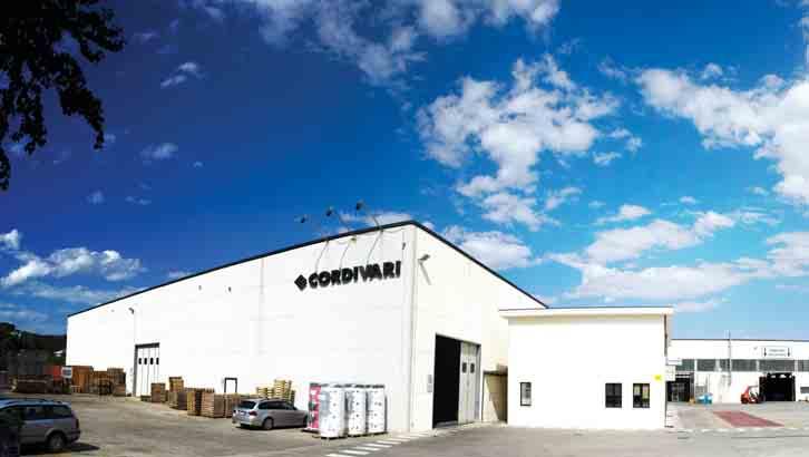
3 Cordivari company has a proven industrial tradi on and is now one of the most important manufacturers in the hea ng and plumbing industry in Italy. Founded in 1972 by Ercole Cordivari, the company is producing calorifiers & buffer tanks, solar thermal systems, compressed air receivers, design radiators, chimney flues and food containers. Cordivari plants are situated on an area of 22. square meters and employ more than 5 employees. Thanks to its development strategies, all addressed to the new technologies and to the training of new human resources, Cordivari is equipped with modern structures and advanced produc on processes. All the products are designed and produced in Italy and the technological, ergonomic and ecological choices allow to work respec ng the human being and its environment. UNI EN ISO 141:24 environment managing systems and UNI EN ISO 91:28 Quality system are perfectly integrated to grant and ensure company s main goals and values. The highly qualified management, the constant research for innova ve solu ons and the extremely customer-oriented company policy stand for the leading market posi on and the exclusive know-how in the field of integrated hea ng systems that the Cordivari group has acquired. All this is the result of a con nuous commitment to achieving Customer Sa sfac on. Cav. Ercole Cordivari 1


4 WELLNESS and SAVING Solutions for your Home T A R B E S R R S M ANFORA T A H Forced Ven lat Radiator SOFI W T 2


5 C P F C C D R R S S C T S S F V R W T R G T C I S T S S I S C B T H P CTS P B G - CAL PE M ANFORA Food container JOLLY d W T 3


6 4
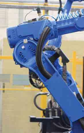
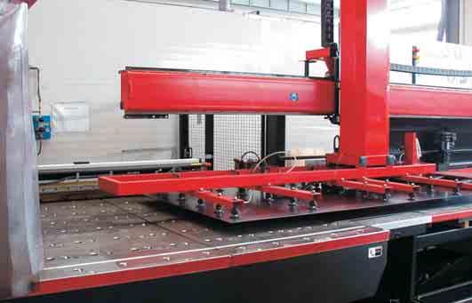
7 Technologies for Wellness Development, design and innova on studies are key points in Cordivari produc on process. Each proposed solu on conveys technical reliability, design, ergonomics and ease use and installa on. The con nuous development of our product offer, wants to witness the company s a en on to the market needs. Similarly, the research and development of new solu ons follows the trends of an efficiency and energy savings oriented market. The different phases of produc on are in perfect harmony with the best techniques for industrial automa on, robo cs and advanced cra smanship. Every product undergoes several mes during the produc on stages, a rigorous control, manual and visual. c ordivari products meet the most important cer fica ons, such as the PED (Pressure Equipment Direc ve) and the Direc ve 29/125/CE (ErP eco-friendly planning regula ons) in compliance with the cylinders and other pressure vessels manufactured. All items for Domes c Hot Water storage are cer fied for drinkable water use in accordance with the strictest Italian and foreign regula ons (ACS, SSICA DVGW W27 UBA, WRAS). In Cordivari quality care and a en on to the environment has always been home. In fact we were the first company of the hea ng sector to obtain the cer fica on according to UNI EN ISO 91: 28 integrated with environmental management cer fica on UNI EN ISO 141: 24. This produc on philosophy, which is now a way of life for us, means reduc on of emissions and energy inefficiencies, waste reduc on and recycling over 6% and allows us to operate in a sustainable and environmentally friendly way, using clean energy from renewable sources, using only ecofriendly materials from raw materials to packaging. CERTIFICATIONS Quality systems cer fied UNI EN ISO 91:28 Environment cer fica on UNI EN ISO 141:24 TÜV Rheinland Energie und Umwelt GmbH states that test procedures and Cordivari LAB are cer fied conforming to European standard EN 15332, as indicated by Ecodesign ErP Direc ve. PRODUCT CERTIFICATIONS ErP POLITECNICO DI MILANO Italian Stainless Steel Associa on 97/23/CE-P.E.D. 87/44/CE ErP Products in conformity to EUP Direc ve Energy Using Products - 25/32/CE Dipartimento di Energia RELAB- Renewable Heating and Cooling LAB CERTIFICATES OF CONFORMITY Internal treatment for food use Polywarm in accordance with D.M. nr. 174 del 6/4/24 granted by SSICA Laboratory of Parma - Italy. A.C.S. Cer fi ca on (A esta on de Conformité Sanitaire) granted by CARSO Laboratoire Santé Environnement Hygiène De Lyon about Polywarm an -corrosion treatment DVGW W27 UBA KTW on Polywarm internal coa ng 5 Water Regula on Advisory Scheme cer fi cate
8 ICONE Domes c Hot Water produc on (D.H.W.) Hea ng Water Produc on GUIDE WHEN CHOOSING A CALORIFIER A calorifier is an indirect water hea ng appliance (i.e. one that features at least one heat exchanger) which accumulates heat so as to handle consump on rates that may vary greatly over a period of me, while also limi ng the power used by the generators. grey STOCK AVAILABILITY STOCK AVAILABILITY Grey highlighted products are available in stock and can be dispatched in 1-5 working days. Cordivari offers a wide and varied range of calorifiers and buffers, to provide the most suitable product to any need and also allow simultaneous use of more energy sources. Calorifiers with tradi onal boilers: These products are designed for use with conven onal boilers which use water as a hea ng medium in a sealed or open expansion circuit. The heat exchangers are designed to handle high flow rates on the primary side to ensure that the heat transfer will be efficient while at the same me avoiding excessively low return water temperatures. Calorifiers with biomass boilers: The selec on of a calorifier while opera ng in conjunc on with a biomass boiler must take account of fact that excessively low return water temperatures could reduce the lifespan of the boiler. In addi on, a calorifier with a larger accumula on volume than normal will be more suitable as it will act as a buffer which will be beneficial to the biomass boiler. Calorifiers with condensing boilers: Condensing boilers are highly efficient and ecologically friendly. They operate at op mum performance when the flow water temperature is limited which results in the return water temperature being as low as possible. This will ensure that the latent heat is extracted out of the combus on products which will maximise the efficiency of the system. Calorifiers with solar systems: The heat exchange coil surface area is a cri cal issue when interfacing solar thermal systems with calorifiers due to limited primary flow rates and temperatures. The calorifier must also be capable of ac ng as a buffer to harness the solar energy throughout daylight hours. Calorifiers opera ng with more than one energy source The demand to heat a calorifier using more than one energy source, while at the same me keeping the various circuits separate, has become much more common in recent mes with the advent of renewable technologies which usually need to be backed-up with conven onal boilers. In these cases, calorifiers with a number of heat exchangers are used with the design ensuring that excellent thermal stra fica on will be achieved with minimal interference between the various heat sources. Calorifiers with heat pumps: Calorifiers opera ng in conjunc on with air-to-water or water-to-water heat pumps must have extremely oversized heat exchange surface areas to ensure that heat exchange will take place even when there is a limited difference in temperature between the primary circuit and secondary stored water. This will maximise the COP (coefficiency of performance) of the heat pump. Calorifiers opera ng with renewable energies D.H.W. produc on system connected to renewable energies, exploi ng natural resources coming from air, water and ground. Calorifiers with steam boilers: The use of saturated steam as a hea ng medium to produce domes c hot water, although li le used in the housing sector, is a solu on which is s ll employed in industrial environments where the steam is already in use for the manufacturing process. Technically speaking, steam calorifiers are charactorised by rela vely small heat exchangers, as on one hand the steam gives high heat exchange coefficients and on the other hand the exchangers usually operate with considerable differences in temperature between the primary and secondary circuits. The use of steam demands a more stringent safety regeime than the use of low pressure hot water systems as steam boilers, depending on their capacity and design pressures, are classified as higher risk and therefore must comply with the European Pressure Equipment Direc ve. Calorifiers opera ng with electrical power Cordivari products designed for working with electricity can be connected to A/C power supply. Combined with a renewable energy power supply system (fotovoltaic, wind energy, and so on), it allows to have an environmental friendly system. Domes c Hot Water produc on (D.H.W.) GUIDE WHEN CHOOSING STORAGE TANKS A storage tank is a well insulated tank that is inserted in hea ng systems powered by a biomass generator. It has the dual func on of allowing the generator to operate in a regular manner, restric ng the number of stoppages, and of crea ng a thermal stabiliser for the hea ng system, thus improving working comfort considerably. Cordivari offers a wide range of storage tanks, which include both standard versions and a number of combined versions to be used as a single appliance, ac ng both as a storage tank and to produce domes c hot water. Central hea ng systems with one or more boilers which are plumbed together and do not generate domes c hot water. Central hea ng systems with one or more boilers which are plumbed together in conjunc on with solar power which is connected to either one or two coil type heat exchangers. Domes c hot water is not generated in these tanks. Hea ng systems with one or more sources hydraulically divided, with the exploita on of the solar power and without DHW produc on. These are hea ng systems powered by a biomass generator or more generators that are hydraulically divided. The prepara on of the DHW is done without involving the hea ng hot water storage tank Combined central hea ng system and domes c hot water produc on with one or more boilers which are plumbed together. Combined central hea ng system and domes c hot water produc on with one or more boilers which are plumbed together. Combined central hea ng system and domes c hot water produc on with one or more boilers which are plumbed together. 6


9 PRODUCT NEWS 216 RANGE OF CALORIFIERS FOR HEAT PUMPS Installa ons with heat pumps represent one of the most developed segments in single or mul use systems. Cordivari extends the range of calorifiers for heat pumps. In this edi on of the catalogue they have an en re sec on dedicated, which is enriched with more models and each one is specialized for its own applica on. Cordivari offers calorifiers that can sa sfy every possible applica on concerning accumula ons for heat pumps, from buffers to mul -heat energy buffers used both for DHW produc on and for hea ng, and also tanks used only for DHW produc on. Made to be combined with heat pumps, high performance tanks can op mize the working process and performances thanks to systems and exchange surfaces specific for those applica ons. Tanks for heat pump range includes tanks from the series Bolly XL and Bolly PDC, and also mul -heat energy buffers from the series Eco- Combi PDC and Puffermas PDC. NEW BOLLY PDC RANGE New Bolly PDC tanks represent the most advanced of tanks for heat pumps evolu on, with a higher level of comfort and performances. Cordivari presents the new DHW prepara on and storage tanks range, expressly designed to use heat pumps as primary energy source. They work through a group of heat exchange, properly dimensioned in order to guarantee several benefits and minimize the hea ng me. Its main feature is a higher efficiency and a constant exchanged power during the prehea ng phase rather than tradi onal tanks, where the exchanged power decreases as the storage temperature increases. Many performance benefits derive from it, such as an important decrease of the star ng me of 25% than a tradi onal tank. This advantage is even bigger in combined systems with heat pump (for DHW and hea ng), where a higher level of comfort is produced by reducing the me to prepare the domes c water in order to dedicate more me to heat the environment. Compared to a tradi onal tank, the exchange system of the new Bolly PDC improves the working condi ons of the generator. Such result is due to the constant exchanged power that reduces the turning on and off cycles, it produces a higher overall performance and extends the heat pump lifecycle. The Bolly PDC range is available as mul -heat models (employing many energy sources) to integrate the solar thermal system or a tradi onal/condensing tank by using big exchangers. De Df (15) H13 (14) PRS MODULE FOR IMMEDIATE DHW PREPARATION PRS modules extend the range of immediate DHW produc on system to afford a higher flow rate or to cope with systems for many users. The new PRS modules are made for immediate prepara on (without storage) or semi-immediate (combined with a DHW accumulator) to be installed in medium or big systems. They guarantee high performances for con nuous DHW produc on with high flow rates. PRS modules work separately from the primary system energy circuit, so to be used with different heat generators (tradi onal, condensing, biomass, district hea ng, etc). Thanks to an advanced electronic control unit they are able to automa cally control several system models, punctually managing the an -legionellosis cycles, recording data and their results. PRS modules are equipped with a plate heat exchanger, high efficiency primary circula on pump (single or double to guarantee the supply even in case of breakdowns), primary mixing valve to avoid calcareous deposits, electronic panel for PLC management and control, besides a temperature feeler system. ErP 217 READY TANK RANGE From September, 26th 217, the Energy Related Products 29/125/CE ErP direc ve will introduce strict laws concerning water storage, both for DHW and hea ng, in order to face an increasing demand of more efficient products and higher heat performances. As from that date, storage tank ll 2 lt. must belong to C-energy efficiency class. This is the reason why Cordivari has already chosen to offer a complete tank and mul -energy range conformed to the European standard that will be effec ve on September, 26th 217. All the products included in the HE tanks and mul -heat energy buffers series represent a higher performance range and they are designed for those who prefer to choose quality and efficiency as from now. 1 C A E ALL HE SERIES PRODUCT WILL BE AVAILABLE STARTING FROM 216 7


10 READY TO SUPPORT YOU! ECODESIGN E P DIRECTIVE 29/125/CE The ErP direc ve Energy Related Products 29/125/CE is about several ac ons to reduce energy costs of the products used for hea ng and to produce DHW through an eco-friendly planning. As from September 26th 215 the direc ve will represent an important change in the European Union regarding these products. It has been created to help the EU to achieve the goals established in the plan 2-2-2, which states that we will reduce 2% of the CO2 emissions, increase 2% of the renewable energies use and obtain 2% of energy saving. THE PRODUCTS INVOLVED All of them are products used for hea ng and to produce DHW, limited to the nominal thermal power of the system and/or the accumula on capacity related to the type of product. According to the legisla on, these products can be part of the market only if they have an energe c label and/ or clear specifica ons about the energe c performances and/or the energy efficiency class. Besides the documents about the product informa on (labels and specifica ons), there will be energe c labels which highlight the general energy efficiency class of a group made by many components. Thanks to this iden fica on the consumer will be able to easily iden fy the efficiency of a product or a system and compare them, as well as technologies, so to choose more and more efficient products. in order to be conform to the legisla on through a series of services which will involve the professionals of this field, such as installers, sellers or engineers. The informa on about the energe c performances will be on each product as stated by the direc ve, but also on catalogues, brochures and price lists. Moreover, all the documents will be available online visi ng it to easily and quickly see or download them. Thanks to the brand new online tool on our website and using a computer or a mobile device, you can get all the documents and generate product labels or system labels in case of systems with many components. You can save all the se ngs and the documents in your personal page, always use or modify them wherever you are. Furthermore, the Cordivari technical department is always ready to support you in case of dimensioning of complex systems or customized confi gura ons. ErP WHAT WILL BE DIFFERENT AS FROM SEPTEMBER 26TH 215? As from September 26th, 215, the products must have the energe c label. For tanks and mul -heat energy buffers, all the models ll 5 lt need the label, while for the models ll 2 lt the informa on about the energy efficiency is indicated on the technical data sheet of the product. From September 26th, 215 there will be more restric ve measures, before this date no minimum energy efficiency class is demanded. When the ErP direc ve will come into force, Cordivari products will show their quality, performances and reliability as always and also their energy performance. So you can see how Cordivari s eco-friendly planning helps you to obtain a growing efficiency that produces wellness and energy saving. Y... ALL OUR SUPPORT AT YOUR DISPOSAL As from September 26th 215 all the necessary tools will be at your disposal 8


11 CORDIVARI S.r.l. Zona Industriale Pagliare 642 MORRO D ORO (TE) Italia Tel r.a. - Fax UFF: COMM: Fax CENTR C.F. - P. IVA - REG. IMPRESE TE N. IT R.E.A. TE N CAP. SOC..4.., i.v. info@cordivari.it APPROVED CERTIFIED QUALITY CHOOSE SERENITY Today, more than ever, who choose Cordivari products choose to be peaceful! By introducing the new Ecodesign ErP standards, we choose to offer you guaranteed performances and reliability. The construc on of the new building Cordivari LAB is the result of this choice. As from the beginning of this year, the company is equipped with a laboratory and an advanced test room which allow to test any product or system, measuring and cer fying its performances. Thanks to its strict procedures, conformed to European standards, and sophis cated tools, nowadays Cordivari is the only Italian manufacturer able to carry out accurate tests on every product in its own laboratory. As a consequence, research and development on performance and energy efficiency are always running towards the best solu ons, in order to guarantee you reliability, savings and high results. Cordivari LAB is the only qualified laboratory inside a manufacturing company, approved by the TÜV. Choose to be safe with cer fied quality! EXAMPLE OF LABEL FOR TANK WITH HEAT PUMP EXAMPLE OF LABEL FOR TANK/MULTI-HEAT ENERGY BUFFERS Manufacturer - name Manufacturer- name DHW Load profile Hot water tank Energy efficiency class Energy efficiency class Sound power level Heat Loss Consump on in different clima c levels per year Net volume 9
12 EXTRA CALORIFIERS C BOLLY AND INTERKA CALORIFIERS 316L STAINLESS STEEL CALORIFIERS HOT WATER BOILERS FOR HEAT PUMP NEW B T BUFFER TANKS NEW MULTIFUEL ENERGY CYLINDERS H MACS MODULE PRS MODULE PLATE HEAT EXCHANGERS COLD/HOT WATER AIR I T W P C C A R HEAT PUMP ENERGY BUFFER TANK CHILLED WATER AND HEATING TANKS PRESSURE VESSEL / EXPANSION VESSEL COMPRESSED AIR RECEIVERS ( / CE / /CE) ACCESSORIES AND SPARE PARTS E O I - C - R - G S C W 1

13 P. 12 P. 68 P. 16 NEW NEW NEW P. 122 NEW P. 144 P. 16 NEW P. 196 NEW P. 214 P. 224 P. 234 P C P

14 12

15 E C D.H.W. S CALORIFIERS 13
16 EXTRA CALORIFIERS RANGE C ErP C C ACCUMULATION TANKS D H W S P.E.D. product planned and produced in conformity to the ar cle 3.3 of direc ve 92/23/CE 14

17 EXTRA EXTRA COMPACT EXTRA PLUS EXTRA VAPORE PIASTRATERM E C D.H.W. S HEAT EXCHANGERS RANGE P.E.D. product planned and produced in conformity to the ar cle 3.3 of direc ve 92/23/CE VASO INERZIALE VASO INERZIALE A1 An legionella Heat Exchanger, with tubes bent to the bo om STAINLESS STEEL 316L or COPPER Straight heat exchanger STAINLESS STEEL 316L or COPPER Straight heat exchanger STAINLESS STEEL 316L (for steam generators) Straight double spiral finned heat exchangers COPPER Plate heat exchangers inspec onable or braze-welded STAINLESS STEEL 316L 15
18 EXTRA1 C POLYWARM GALVANIZED POLYWARM Accessories APPLICATION Produc on and storage of sanitary hot water. MATERIAL Material and finishings, suitable for drinkable water according to D. M. n. 174 dated 6.4.4,: - Mild steel Polywarm coated (cer fica on ACS - SSICA - DVGW - W27 - UBA - WRAS) - Galvanized Steel HEAT EXCHANGER: An legionella Heat Exchanger, with tubes bent to the bo om (available on Stainless Steel 316L or Copper). INSULATION NOFIRE polyester fibre 1% made of recyclable material, with high thermal insula on. Fire resistance class B-s2d according to EN Grey PVC external lining complete with top and flange cover HE SERIES: High thermal insula on with ecological hard ANTILEGIONELLA HEAT EXCHANGER HEAT EXCHANGER STAINLESS STEEL 316L OK EXTRA 1 HE SERIES Easy Control Electronic Display ART. NR , STANDARD , HE SERIES EXTRA 1 WXC VT 16 E E C D.H.W. Storage: POLYWARM coated Heat Exchanger: STAINLESS STEEL Art. Nr. Price , E , E , E , F , F , F , G , , , , grey STOCK AVAILABILITY TECHNICAL DATA AND ECODESIGN ERP LABE L S AVAILABLE ONLINE AT ErP HIGH EFFICIENCY INSULATION TANKS Designed according to 29/125/CE Direc ve (ErP Eco-friendly Plan Specifica on), HE series are already complaint with Regula on n. 814/213, that demands C-energy efficiency class from September, 26th 217. polyurethane foam. CATHODE PROTECTION Magnesium anode with anoden tester (Polywarm ) - Magnesium anode (Galvanized) - s > 15 n 2 magnesium anodes. DRAIN External confluence through drain connec on. s > lt 1 external confluence through drain pipe. GASKET FLANGE PLATE Silicone gaskets suitable for alimentary use for max temperature up to 2 C. Mild steel exchanger head with an corrosion treatment. WARRANTY - 5 years (Polywarm ) - 2 years (Galvanized) - See general sales condi ons and warranty. ACCESSORIES AND SPARE PARTS : See Accessories sec on for the en re list. EXTRA 1 WRC VT E E C D.H.W. Storage: POLYWARM coated Heat Exchanger: ErP COPPER Art. Nr. Price , E , E , E , F , F , F , G , , , , EXTRA 1 ZRC VT E E C D.H.W. Storage: GALVANIZED coated Heat Exchanger: ErP COPPER Art. Nr. Price , E , E , E , F , F , F , G , , , , EXTRA 1 WXB HE VT Monophase and Threephase electric resistances See accessories sec on D.H.W. Storage: POLYWARM coated Heat Exchanger: STAINLESS STEEL E E C ErP Art. Nr. Price , C , C , C , C , C , C , C Titanium electronic anode See accessories sec on H Lower [m 2 ],5,75 1 1, H Lower [m 2 ],5,75 1 1, H Lower [m 2 ],5,75 1 1, Also available customized versions with copper exchanger both for Polywarm and galvanized coated models. P.E.D. product planned and produced in conformity to the ar cle 3.3 of direc ve 92/23/CE
19 EXTRA1 C FINISHING STORAGE HEAT EXCHANGERS Pmax Tmax Pmax Tmax 2 1 POLYWARM 8 bar 9 C 12 bar 11 C 15 5 POLYWARM 6 bar 2 1 GALVANIZED 8 bar 15 5 GALVANIZED 6 bar 6 C 12 bar 11 C De TÜV Rheinland Energie und Umwelt GmbH states that test procedures and Cordivari LAB are cer fied conforming to European standard EN 15332, as indicated by Ecodesign ErP Direc ve. E C D.H.W. S (14) H16 (1) H17 (11) (12) (13) H15 (9) A 1 Drain 2 Domes c cold water circuit inlet H H6 (7) H4 (5) H7 (8) (16) H5 (6) H3 (4) 3 Alterna ve domes c cold water circuit inlet or connec on for more boilers 4 Hea ng water back to the buffer 5 Heat exchanger flange H2 (2) (3) 6 Entry hea ng water from the buffer 7 Connec on for instrumenta on 1/2 Gas F H1(1) 8 Connec on for magnesium anode 1 1/4 Gas F 9 Connec on for 2nd anode 1 1/4 Gas F (only for models > 15 ) P.E.D. product planned and produced in conformity to the ar cle 3.3 of direc ve 92/23/CE (1) (2) (11) (7) (1) (12) (14) (4) (5) (6) (16) (8) (9) (3) (13) H1 (15) Tanks from 15 to 5 have two gripps on the bo om which allow the use of forkli when handling and drain pipe already fi ed Connec on for electrical immersion 1 1/2 Gas F - for models > 8 connec ons 2 Gas F Connec on for recircula on or for domes c hot water 12 Connec on for instrumenta on 1/2 Gas F 14 Domes c hot water outlet 15 Drain 1 Gas F (only for models > di 1 ) 16 Air spurge heat exchanger 3/8 Gas F Net Volume Weight De De HE SERIE) H A H1 H2 H3 H4 H5 H6 H7 [litres] [kg] [mm] // // // // H15 H16 H [mm] Connec ons Gas F 2 // Øe 3 1"1/4 1"1/4 1" 1/2" 1"1/4 // 1"1/2 1 1/4 3 // Øe 3 1"1/4 1"1/4 1" 1/2" 1"1/4 // 1"1/2 1 1/4 5 // Øe 3 1"1/4 1"1/4 1" 1/2" 1"1/4 // 1"1/2 1 1/4 8 // Øe 38 1"1/4 1"1/4 2" 1/2" 1"1/4 // 1"1/2 1"1/2 1 // Øe 38 1"1/2 1"1/2 2" 1/2" 1"1/4 // 2" 2" 15 // Øe 38 // 1"1/2 2" 1/2" 1"1/4 // 2" 2" Øe 43 // 2" 2" 1/2" 1"1/4 1"1/4 2" 2" Øe 43 // 2" 2" 1/2" 1"1/4 1"1/4 2" 2" Øe 43 // 2" 2" 1/2" 1"1/4 1"1/4 2" 2" Øe 43 // 2" 2" 1/2" 1"1/4 1"1/4 2" 2" Øe 43 // 2" 2" 1/2" 1"1/4 1"1/4 2" 2" 17
20 EXTRA1 - H Cordivari Heat Exchangers, with tubes bent to the bo om, is able to heat the complete quan ty of volume in an homogeneus way. Energy storaging is therefore improved and Igni on me data have to be referred to the complete volume of the tank, while in a tradi onal straight heat exchangers equipped calorifires, a range between 9-17% of Volume remain cold. t2 T1 T2 t1 C H E Storage Volume [litres] Igni on me (minutes) from 1 C to t2 and primary at t1 P - C H E Chart for surfaces of:,5 m 2 /,75 m 2 / 1 m Maximum power exchange (kw) with primary at t1, secondary within 1-45 C and constant use of DHW produc on T1/t2 T1 T1 6 5 DHW con nuous produc on lt/h within 1-45 C and primary at t1 55/5 65/6 7/6 8/ ,3 11,5 13, ,8 8,9 1,5 13, , ,9 13,8 16,3 21, ,8 28, ,1 18,7 22,1 29, , Flow Rate [l./min] ,5 m Chart for surfaces of: 1,5 m 2 / 2 m 2 / 3 m 2 Flow Rate [l./min] ,5 m 2 5, [mm H 2 O] ,75 m [mbar] [mm H 2 O] m 2 3 m 2 4, 3, [mbar] 6 1 m , , 2 2, Flow Rate [m 3 /h] Flow Rate [m 3 /h] I A Storage volume: Standard heat exchanger Storage volume: Heat exchanger for 1% heated volume Advantage in storaged volume Advantage in percentage [litres] [litres] [litres] [%] % % % % % 18 %
21 EXTRA1 - H Data have been calculated on following basis: 1) Primary circuit at T1 and proper energy source; 2) Produc on of DHW in con nue way from 1 C at t2; 3) DHW that can be taken in the first 1 and in the first hour from storage at 6 C, input 1 C and output 45 C; 4) Sanitary water according to UNI CTI 865. E C D.H.W. S DHW produced in the first 1 minutes in lt/1 input 1 C output 45 C, storage at t2 and primary at T1 T1/t2 DHW produced in the first hour in lt/6 input 1 C output 45 C, storage at t2 and primary at T1 T1/t2 Flow rate Exchanger pressure loss 55/5 65/6 7/6 8/6 55/5 65/6 7/6 8/6 [m 3 /h] [mm.h 2 O] [mbar] , ,74 8, , ,5 11,2 9, , ,381 11, , ,22 18, , ,5 35, , ,5 589,6 57, , ,42 75, , , , , , , , ,9 [mm H 2 O] Chart for surfaces of: 4 m 2 / 5 m 2 / 6 m 2 Flow Rate [l./min] m m m [mbar] [mm H 2 O] Chart for surfaces of: 8 m 2 / 1 m 2 Flow Rate [l./min] m m [mbar] Flow Rate [m 3 /h] Flow Rate [m 3 /h] Storage volume: Standard heat exchanger Storage volume: Heat exchanger for 1% heated volume Advantage in storaged volume Advantage in percentage [litres] [litres] [litres] [%] % % % % % % 19
22 EXTRA1 COMPACT C - APPLICATION Produc on and storage of sanitary hot water suitable for lowceilinged rooms. MATERIAL Material and finishings, suitable for drinkable water according to D. M. n. 174 dated 6.4.4,: - Mild steel Polywarm coated (cer fica on ACS - SSICA - DVGW - W27 - UBA - WRAS) HEAT EXCHANGER: An legionella Heat Exchanger, with tubes bent to the bo om (available on Stainless Steel 316L or Copper). INSULATION NOFIRE polyester fibre 1% made of recyclable material, with high thermal insula on. Fire resistance class B-s2d according to EN Grey PVC external lining complete with top and flange cover HE SERIES: High thermal insula on with ecological hard polyurethane foam. CATHODE PROTECTION n 2 magnesium anodes with Anoden Tester (Polywarm ). DRAIN External confluence through drain connec on. s > lt 1 external confluence through drain pipe. GASKET FLANGE PLATE Silicone gaskets suitable for alimentary use for max temperature up to 2 C. Mild steel exchanger head with an corrosion treatment. WARRANTY - 5 years (Polywarm ) See general sales condi ons and warranty. ACCESSORIES AND SPARE PARTS: See Accessories sec on for the en re list. POLYWARM ANTILEGIONELLA HEAT EXCHANGER HEAT EXCHANGER STAINLESS STEEL 316L OK EXTRA 1 WXC VT COMPACT E E C D.H.W. Storage: POLYWARM coated Heat Exchanger: ErP STAINLESS STEEL Art. Nr. Price , F , G , , , H Lower [m 2 ] POLYWARM Accessories on request Easy Control Electronic Display ART. NR. E , STANDARD , HE SERIES TECHNICAL DATA AND ECODESIGN ERP LABE L S AVAILABLE ONLINE AT Thermometer Art. Nr , 5 units box EXTRA 1 WRC VT COMPACT E E C D.H.W. Storage: POLYWARM coated Heat Exchanger: ErP COPPER Art. Nr. Price , F , G , , , Titanium electronic anode Art. Nr , 1, , 2 4 H Lower [m 2 ] Suitable for Polywarm coated models P.E.D. product planned and produced in conformity to the ar cle 3.3 of direc ve 92/23/CE 2
23 EXTRA1 COMPACT C - E C D.H.W. S FINISHING STORAGE HEAT EXCHANGERS Pmax Tmax Pmax Tmax POLYWARM 6 bar 9 C 12 bar 11 C TÜV Rheinland Energie und Umwelt GmbH states that test procedures and Cordivari LAB are cer fied conforming to European standard EN 15332, as indicated by Ecodesign ErP Direc ve. SUITABLE FOR LOW-CEILINGED ROOMS MAX HEIGHT 25 cm (14) De A 1 Drain 1 Gas F H H16 (1) H6 (7) H4 (5) H2 (2) (3) H17 (11) (12) (13) H15 (9) H7 (8) (16) H5 (6) H3 (4) 2 Domes c cold water circuit inlet 3 Alterna ve domes c cold water circuit inlet or connec on for more boilers 4 Hea ng water back to the buffer 5 Heat exchanger flange 6 Entry hea ng water from the buffer 7 Connec on for instrumenta on 1/2 Gas F H1(1) 8 Connec on for magnesium anode 1 1/4 Gas F 9 Connec on for 2nd anode 1 1/4 Gas F (only for models > 15) 1 Connec on for electrical immersion (1) (2) (11) (14) (3) (13) 11 Connec on for recircula on or for domes c hot 13 water 12 Connec on for instrumenta on 1/2 Gas F 14 Domes c hot water outlet 2 Gas F 16 Air spurge heat exchanger 3/8 Gas F (7) (1) (12) (8) (9) P.E.D. product planned and produced in conformity to the ar cle 3.3 of direc ve 92/23/CE (4) (5) (6) (16) H1 (15) The calorifier has two gripps on the bo om which allows the use of forkli when handling and already equipped with mounted drainage tube. Net Volume Weight De H A H1 H2 H3 H4 H5 [litres] [kg] [mm] H6 H7 H15 H16 H [mm] Connec ons Gas F // Øe 38 2" 2" 1/2" 1"1/4 // Øe 43 2" 2" 1/2" 1"1/4 1"1/ Øe 43 2" 2" 1/2" 1"1/4 1"1/ Øe 43 2" 2" 1/2" 1"1/4 1"1/ Øe 43 2" 2" 1/2" 1"1/4 1"1/4 21
24 EXTRA1 COMPACT- H Cordivari Heat Exchangers, with tubes bent to the bo om, are able to heat the complete quan ty of volume in an homogenous way. Energy storaging is therefore improved and Igni on me data have to be referred to the complete volume of the tank, while in a tradi onal straight heat exchangers equipped calorifires, a range between 9-17% of Volume remain cold. t2 T1 T2 t1 C H E Storage Volume [litres] Igni on me (minutes) from 1 C to t2 and primary at t1 P - C H E Maximum power exchange (kw) with primary at t1, secondary within 1-45 C and constant use of DHW produc on DHW con nuous produc on lt/h within 1-45 C and primary at t1 T1/t2 T1 T1 55/5 65/6 7/6 8/ Chart for surfaces of: 3 m 2 Flow Rate [l./min] , 4 4, [mm H 2 O] 3 3 m 2 3, [mbar] 2 2, P - C H E 1 1,, Flow Rate [m 3 /h] Chart for surfaces of: 4 m 2 Flow Rate [l./min] Chart for surfaces of: 5 m 2 Flow Rate [l./min] [mm H 2 O] m [mbar] [mm H 2 O] m [mbar] Flow Rate [m 3 /h] Flow Rate [m 3 /h] 22
25 EXTRA1 COMPACT- H Data have been calculated on following basis: 1) Primary circuit at T1 and proper energy source; 2) Produc on of DHW in con nue way from 1 C at t2; 3) DHW that can be taken in the first 1 and in the first hour from storage at 6 C, input 1 C and output 45 C; 4) Sanitary water according to UNI CTI 865. E C D.H.W. S DHW produced in the first 1 minutes in lt/1 input 1 C output 45 C, storage at t2 and primary at T1 DHW produced in the first hour in lt/6 input 1 C output 45 C, storage at t2 and primary at T1 Flow rate Exchanger pressure loss T1/t2 T1/t2 55/5 65/6 7/6 8/6 55/5 65/6 7/6 8/6 [m 3 /h] [mm.h 2 O] [mbar] , ,5 589,6 57, , ,42 75, , , , , , , P - C H E Chart for surfaces of: 6 m 2 Flow Rate [l./min] [mm H 2 O] m [mbar] P - C H E Flow Rate [m 3 /h] Chart for surfaces of: 8 m 2 Flow Rate [l./min] m [mm H 2 O] [mbar] Flow Rate [m 3 /h] 23
26 EXTRA - H H E / C DHW (U, ) Output [KW] m 2 1,5 m Primary circuit temperature [ C] Extractable heat exchanger surface 1,5 m 2 2 m 2 Primary flow rate [m 3 /h] MAX MIN MAX MIN Output [KW] m 2,75 m 2,5 m Primary circuit temperature [ C] Extractable heat exchanger surface,5 m 2,75 m 2 1 m 2 Primary flow rate [m 3 /h] 24 MAX MIN MAX MIN MAX MIN ,5 4 2
27 EXTRA - H E C D.H.W. S m 2 Output [KW] m m Primary circuit temperature [ C] Extractable heat exchanger surface 4 m 2 6 m 2 1 m 2 Primary flow rate [m 3 /h] MAX MIN MAX MIN MAX MIN m 2 25 Output [KW] m m Extractable heat exchanger surface 3 m 2 5 m 2 8 m 2 Primary flow rate [m 3 /h] MAX MIN MAX MIN MAX MIN 15 7,
28 EXTRA2 C POLYWARM POLYWARM APPLICATION Produc on and storage of sanitary hot water. MATERIAL Material and finishings, suitable for drinkable water according to D. M. n. 174 dated 6.4.4,: - Mild steel Polywarm coated (cer fica on ACS - SSICA - DVGW - W27 - UBA - WRAS) HEAT EXCHANGER: 2 heat exchangers, (upper: straight - lower: An legionella with tubes bent to the bo om - available on stainless steel 316L or copper. INSULATION NOFIRE polyester fibre 1% made of recyclable material, with high thermal insula on. Fire resistance class B-s2d according to EN Grey PVC external lining complete with top and flange cover ANTILEGIONELLA HEAT EXCHANGER HEAT EXCHANGER STAINLESS STEEL 316L OK EXTRA 2 HE SERIES HIGH EFFICIENCY INSULATION TANKS Accessories on request TECHNICAL DATA AND ECODESIGN ERP LABE L S AVAILABLE ONLINE AT Designed according to 29/125/CE Direc ve (ErP Eco-friendly Plan Specifica on), HE series are already complaint with Regula on n. 814/213, that demands C-energy efficiency class from September, 26th 217. POLYWARM Easy Control Electronic Display ART. NR , STANDARD , HE SERIES grey STOCK AVAILABILITY 26 HE SERIES: High thermal insula on with ecological hard polyurethane foam. CATHODE PROTECTION Magnesium anode with anoden tester (Polywarm ) - s > 15 n 2 magnesium anodes. DRAIN External confluence through drain connec on. s > lt 1 external confluence through drain pipe. GASKET FLANGE PLATE Silicone gaskets suitable for alimentary use for max temperature up to 2 C. Mild steel exchanger head with an corrosion treatment. WARRANTY - 5 years - See general sales condi ons and warranty. ACCESSORIES AND SPARE PARTS: See Accessories sec on for the en re list. EXTRA 2 WXC VT E E C D.H.W. Storage: POLYWARM coated Heat Exchanger: STAINLESS STEEL Art. Nr. Price , E , E , E , F , F , F , G , , , , EXTRA 2 WXB HE VT D.H.W. Storage: POLYWARM coated Heat Exchanger: STAINLESS STEEL Monophase and Threephase electric resistances See accessories sec on EXTRA 2 WRC VT ErP E E C D.H.W. Storage: POLYWARM coated Heat Exchanger: COPPER Art. Nr. Price , E , E , E , F , F , F , G , , , , ErP E E C ErP Art. Nr. Price , C , C , C , C , C , C , C H Lower Upper [m 2 ] [m 2 ],5,5,75,75 1,5 1, H Lower Upper [m 2 ] [m 2 ],5,5,75,75 1,5 1, Also available on request customized versions with copper exchanger for Polywarm model. Titanium electronic anode See accessories sec on H Lower Upper [m 2 ] [m 2 ],5,5,75,75 1,5 1, P.E.D. product planned and produced in conformity to the ar cle 3.3 of direc ve 92/23/CE
29 EXTRA2 C FINISHING STORAGE HEAT EXCHANGERS Pmax Tmax Pmax Tmax 2 1 POLYWARM 8 bar 9 C 12 bar 11 C 15 5 POLYWARM 6 bar De TÜV Rheinland Energie und Umwelt GmbH states that test procedures and Cordivari LAB are cer fied conforming to European standard EN 15332, as indicated by Ecodesign ErP Direc ve. E C D.H.W. S (18) A H H16 (14) H11 (12) H9 (1) H6 (7) H4 (5) H2 (2) (3) H1 (1) (1) (2) (15) (18) H17 (15) (16) (17) H15 (13) H7 (8) (3) (17) (2) H1 (11) H8 (9) (19) H5 (6) H3 (4) 1 Drain (models from 2 to 1) 2 Domes c cold water circuit inlet Alterna ve domes c cold water circuit inlet or connec on for more boilers 3 4 Lower heat exchanger outlet 5 Heat exchanger flange 6 Lower heat exchanger inlet 7-12 Connec on for instrumenta on 1/2 Gas F 8 Connec on for magnesium anode 1 1/4 Gas F 9 Lower heat exchanger outlet 1 Upper heat exchanger flange 11 Fixed upper heat exchanger inlet Connec on for 2nd anode 1 1/4 Gas F (only for models > 15) Connec on for electrical immersion 1 1/2 Gas F - for models > 8 connec ons 2 Gas F Connec on for recircula on or for domes c hot water 16 Connec on for instrumenta on 1/2 Gas F 18 Domes c hot water outlet 19-2 Air spurge heat exchanger 3/8 Gas F 21 Drain 1 Gas F (only for models > di 1) (7) (12) (14) (16) (8) (13) (4) (5) (6) (9) (1) (11) (19) (2) (21) H1 (21) Tanks from 15 to 5 liters have two gripps on the bo om which allow the use of forkli when handling and drain pipe already fi ed. P.E.D. product planned and produced in conformity to the ar cle 3.3 of direc ve 92/23/CE Net Volume Weight De De HE SERIE) H A H1 H2 H3 H4 H5 H6 H7 [litres] [kg] [mm] // // // // H8 H9 H1 H11 H15 H16 H [mm] Connec ons Gas F // Øe 3 1"1/4 1"1/4 1" // 1"1/ // Øe 3 1"1/4 1"1/4 1" // 1"1/ // Øe 3 1"1/4 1"1/4 1" // 1"1/ // Øe 38 1"1/4 1"1/4 2" // 1"1/ // Øe 38 1"1/2 1"1/2 2" // 1"1/ // Øe 38 // 1"1/2 2" 1" 2" Øe 43 // 2" 2" 1" 2" Øe 43 // 2" 2" 1" 2" Øe 43 // 2" 2" 1" 2" Øe 43 // 2" 2" 1" 2" Øe 43 // 2" 2" 1" 2" 27
30 EXTRA2 - H Cordivari Heat Exchangers, with tubes bent to the bo om, are able to heat the complete quan ty of volume in an homogenous way. Energy storaging is therefore improved and Igni on me data have to be referred to the complete volume of the tank, while in a tradi onal straight heat exchangers equipped calorifires, a range between 9-17% of Volume remain cold. t2 T1 T2 t1 UPPER STRAIGHT HEAT EXCHANGERS Storage Volume [litres] Maximum power exchange (kw) with primary at t1, secondary within 1-45 C and constant use of DHW produc on T1/t2 T1 T1 Igni on me (minutes) from 1 C to t2 and primary at t1 DHW con nuous produc on lt/h within 1-45 C and primary at t1 55/5 65/6 7/6 8/ t2 T1 T2 t1 C H E Storage Volume [litres] Maximum power exchange (kw) with primary at t1, secondary within 1-45 C and constant use of DHW produc on T1/t2 T1 T1 Igni on me (minutes) from 1 C to t2 and primary at t1 DHW con nuous produc on lt/h within 1-45 C and primary at t1 55/5 65/6 7/6 8/ , , ,
31 EXTRA2 - H Data have been calculated on following basis: 1) Primary circuit at T1 and proper energy source; 2) Produc on of DHW in con nue way from 1 C at t2; 3) DHW that can be taken in the first 1 and in the first hour from storage at 6 C, input 1 C and output 45 C; 4) Sanitary water according to UNI CTI 865. E C D.H.W. S DHW produced in the first 1 minutes in lt/1 input 1 C output 45 C, storage at t2 and primary at T1 T1/t2 DHW produced in the first hour in lt/6 input 1 C output 45 C, storage at t2 and primary at T1 T1/t2 Flow rate Exchanger pressure loss 55/5 65/6 7/6 8/6 55/5 65/6 7/6 8/6 [m 3 /h] [mm.h 2 O] [mbar] ,35 28, ,5 7, ,7 34, ,5 95,97 9, , , , , , , , , , , , , , , , , , , , DHW produced in the first 1 minutes in lt/1 input 1 C output 45 C, storage at t2 and primary at T1 T1/t2 DHW produced in the first hour in lt/6 input 1 C output 45 C, storage at t2 and primary at T1 T1/t2 Flow rate Exchanger pressure loss 55/5 65/6 7/6 8/6 55/5 65/6 7/6 8/6 [m 3 /h] [mm.h 2 O] [mbar] , ,74 8, , ,5 11,2 9, , ,22 18, , ,5 35, , ,5 589,6 57, , ,5 589,6 57, , ,42 75, , , , , , , , ,9 29
32 EXTRA2 - P - LOWER POLYWARM Chart for surfaces of:,5 m 2 /,75 m 2 / 1 m 2 Flow Rate [l./min] ,5 m [mm H 2 O] 12 1,75 m [mbar] m Flow Rate [m 3 /h] Chart for surfaces of: 1,5 m 2 / 2 m 2 / 3 m 2 Flow Rate [l./min] Chart for surfaces of: 4 m 2 / 5 m 2 Flow Rate [l./min] ,5 m 2 5, [mm H 2 O] m 2 3 m 2 4, 3, [mbar] [mm H 2 O] m 2 5 m [mbar] 2 2, , m, Flow Rate [m 3 /h] Flow Rate [m 3 /h] Chart for surfaces of: 6 m 2 / 8 m 2 Flow Rate [l./min] Chart for surfaces of: 1 m 2 Flow Rate [l./min] m m [mm H 2 O] m [mbar] [mm H 2 O] [mbar] Flow Rate [m 3 /h] Flow Rate [m 3 /h] 3
33 EXTRA2 - P - UPPER POLYWARM Chart for surfaces of:,5 m 2 /,75 m 2 / 1 m 2 Flow Rate [l./min] E C D.H.W. S 18,5 m [mm H 2 O] 12 1,75 m [mbar] m Flow Rate [m 3 /h] Chart for surfaces of: 1,5 m 2 / 2 m 2 / 3 m 2 Chart for surfaces of: 4 m 2 / 5 m 2 Flow Rate [l./min] ,5 m , 4 4, 35 35, 2 m 2 Flow Rate [l./min] q , 4, 35, [mm H 2 O] m 2 3, 25, 2, [mbar] [mm H 2 O] m 2 5 m 2 3, 25, 2, [mbar] 15 15, 15 15, 1 5, Flow Rate [m 3 /h] 1, 5, 1 5, Flow Rate [m 3 /h] 1, 5, Chart for surfaces of: 6 m 2 / 8 m 2 Flow Rate [l./min] Chart for surfaces of: 1 m 2 Flow Rate [l./min] , 45 1 m 2 45, m 2 4, 35, , 35, [mm H 2 O] m 2 3, 25, [mbar] [mm H 2 O] , 25, [mbar] 2 2, 2 2, 15 15, 15 15, 1 1, 1 1, 5 5, 5 5,, Flow Rate [m 3 /h], Flow Rate [m 3 /h] 31
34 EXTRA3 C APPLICATION Produc on and storage of sanitary hot water. MATERIAL Material and finishings, suitable for drinkable water according to D. M. n. 174 dated 6.4.4,: - Mild steel Polywarm coated (cer fica on ACS - SSICA - DVGW - W27 - UBA - WRAS). HEAT EXCHANGER: 3 heat exchangers, (upper, middle: straight - lower: An legionella ) with tubes bent to the bo om - available on stainless steel 316L or copper. INSULATION NOFIRE polyester fibre 1% made of recyclable material, with high thermal insula on. Fire resistance class B-s2d according to EN Grey PVC external lining complete with top and flange cover HE SERIES: High thermal insula on with ecological hard polyurethane foam. CATHODE PROTECTION Magnesium anode with anoden tester (Polywarm ) - s > 15 n 2 magnesium anodes. DRAIN External confluence through drain connec on. s > lt 1 external confluence through drain pipe. GASKET FLANGE PLATE Silicone gaskets suitable for alimentary use for max temperature up to 2 C. Mild steel inspec on flange plate with an corrosion treatment. WARRANTY - 5 years - See general sales condi ons and warranty. ACCESSORIES AND SPARE PARTS : See Accessories sec on for the en re list. POLYWARM POLYWARM ANTILEGIONELLA HEAT EXCHANGER HEAT EXCHANGER STAINLESS STEEL 316L OK TECHNICAL DATA AND ECODESIGN ERP LABE L S AVAILABLE ONLINE AT EXTRA 3 WXC VT E E C D.H.W. Storage: POLYWARM coated Heat Exchanger: STAINLESS STEEL Art. Nr. Price , G , G , , EXTRA 3 WRC VT ErP E E C D.H.W. Storage: POLYWARM coated Heat Exchanger: COPPER Art. Nr. Price , G , G , , ErP H Lower Middle Upper [m 2 ] [m 2 ] [m 2 ] 3 3 1, H Lower Middle Upper [m 2 ] [m 2 ] [m 2 ] 3 3 1, EXTRA 3 HE SERIES HIGH EFFICIENCY INSULATION TANKS Designed according to 29/125/CE Direc ve (ErP Eco-friendly Plan Specifica on), HE series are already complaint with Regula on n. 814/213, that demands C-energy efficiency class from September, 26th 217. POLYWARM Accessories on request Easy Control Electronic Display ART. NR , STANDARD , HE SERIES Thermometer Art. Nr , 5 units box 32 EXTRA 3 WXB HE VT E E C D.H.W. Storage: POLYWARM coated Heat Exchanger: STAINLESS STEEL Art. Nr. Price , C , C ErP Titanium electronic anode Art. Nr , , 2 5 H Lower Middle Upper [m 2 ] [m 2 ] [m 2 ] 3 3 1, Also available on request customized versions with copper exchanger for Polywarm model. Suitable for Polywarm coated models P.E.D. product planned and produced in conformity to the ar cle 3.3 of direc ve 92/23/CE
35 EXTRA3 C STORAGE HEAT EXCHANGERS Pmax Tmax Pmax Tmax 6 bar 9 C 12 bar 11 C TÜV Rheinland Energie und Umwelt GmbH states that test procedures and Cordivari LAB are cer fied conforming to European standard EN 15332, as indicated by Ecodesign ErP Direc ve. E C D.H.W. S (21) De A H H13 (14) H11 (12) H9 (1) H6 (7) H4 (5) H2 (2) (3) H17 (15) (16) (17) (18) H15 (13) H7 (8) (25) H14 (2) H12 (19) (24) H1 (11) H8 (9) (23) H5 (6) H3 (4) 1 Drain 1 Gas F 2 Domes c cold water circuit inlet Alterna ve domes c cold water circuit inlet or 3 connec on for more boilers 4 Lower heat exchanger outlet 5 Heat exchanger flange 6 Lower heat exchanger inlet 7-12 Connec on for instrumenta on 1/2 Gas F 8 Connec on for magnesium anode 1 1/4 Gas F 9 Middle heat exchanger outlet 1 Middle Heat exchanger flange P.E.D. product planned and produced in conformity to the ar cle 3.3 of direc ve 92/23/CE H1 (1) (1) (2) (15) (21) (3) (18) (7) (12) (16) (8) (13) (17) (4) (5) (6) (9) (1) (11) (14) (19) (2) (22) (23) (24) (25) The calorifier have two gripps on the bo om which allow the use of forkli when handling and already equipped with mounted drainage tube. 11 Middle heat exchanger inlet 13 Connec on for 2nd anode 1 1/4 Gas F (only for models > 15) 14 Upper heat exchanger flange Connec on for recircula on or for domes c hot water Connec on for instrumenta on 1/2 Gas F 19 Lower heat exchanger outlet 2 Fixed upper heat exchanger inlet 21 Domes c hot water outlet Air spurge heat exchanger 3/8 Gas F Net Volume Weight De De HE SERIE) H A H1 H2 H3 H4 H5 H6 H7 H8 H9 [litres] [kg] [mm] // // H1 H11 H12 H13 H14 H15 H [mm] Connec ons Gas F // 25 Øe 38 Øe 38 1"1/2 2" 1/2" 1"1/4 // 2" Øe 43 Øe 38 2" 2" 1/2" 1"1/4 1"1/4 2" Øe 43 Øe 38 2" 2" 1/2" 1"1/4 1"1/4 2" Øe 43 Øe 43 2" 2" 1/2" 1"1/4 1"1/4 2" 33
36 EXTRA3 - H Cordivari Heat Exchangers, with tubes bent to the bo om, are able to heat the complete quan ty of volume in an homogenous way. Energy storaging is therefore improved and Igni on me data have to be referred to the complete volume of the tank, while in a tradi onal straight heat exchangers equipped calorifires, a range between 9-17% of Volume remain cold. t2 T1 T2 t1 UPPER STRAIGHT HEAT EXCHANGERS Storage Volume [litres] Igni on me (minutes) from 1 C to t2 and primary at t1 Maximum power exchange (kw) with primary at t1, secondary within 1-45 C and constant use of DHW produc on DHW con nuous produc on lt/h within 1-45 C and primary at t1 T1/t2 T1 T1 55/5 65/6 7/6 8/ t2 T1 T2 t1 MIDDLE STRAIGHT HEAT EXCHANGERS Storage Volume [litres] Igni on me (minutes) from 1 C to t2 and primary at t1 Maximum power exchange (kw) with primary at t1, secondary within 1-45 C and constant use of DHW produc on DHW con nuous produc on lt/h within 1-45 C and primary at t1 T1/t2 T1 T1 55/5 65/6 7/6 8/ t2 T1 T2 t1 CURVED HEAT EXCHANGERS Storage Volume [litres] Igni on me (minutes) from 1 C to t2 and primary at t1 Maximum power exchange (kw) with primary at t1, secondary within 1-45 C and constant use of DHW produc on DHW con nuous produc on lt/h within 1-45 C and primary at t1 T1/t2 T1 T1 55/5 65/6 7/6 8/
37 EXTRA3 - H Data have been calculated on following basis: 1) Primary circuit at T1 and proper energy source; 2) Produc on of DHW in con nue way from 1 C at t2; 3) DHW that can be taken in the first 1 and in the first hour from storage at 6 C, input 1 C and output 45 C; 4) Sanitary water according to UNI CTI 865. E C D.H.W. S DHW produced in the first 1 minutes in lt/1 input 1 C output 45 C, storage at t2 and primary at T1 DHW produced in the first hour in lt/6 input 1 C output 45 C, storage at t2 and primary at T1 Flow rate Exchanger pressure loss T1/t2 T1/t2 55/5 65/6 7/6 8/6 55/5 65/6 7/6 8/6 [m 3 /h] [mm.h 2 O] [mbar] , , , , , , , , ,1 DHW produced in the first 1 minutes in lt/1 input 1 C output 45 C, storage at t2 and primary at T1 DHW produced in the first hour in lt/6 input 1 C output 45 C, storage at t2 and primary at T1 Flow rate Exchanger pressure loss T1/t2 T1/t2 55/5 65/6 7/6 8/6 55/5 65/6 7/6 8/6 [m 3 /h] [mm.h 2 O] [mbar] ,3 213, ,5 56,28 54, ,25 279, ,1 71, ,34 269, ,69 68, ,31 438, ,29 28,5 DHW produced in the first 1 minutes in lt/1 input 1 C output 45 C, storage at t2 and primary at T1 DHW produced in the first hour in lt/6 input 1 C output 45 C, storage at t2 and primary at T1 Flow rate Exchanger pressure loss T1/t2 T1/t2 55/5 65/6 7/6 8/6 55/5 65/6 7/6 8/6 [m 3 /h] [mm.h 2 O] [mbar] , ,5 589,6 57, , ,42 75, , , , ,9 35
38 EXTRA3 - P - LOWER Chart for surfaces of:,5 m 2 /,75 m 2 / 1 m 2 Flow Rate [l./min] ,5 m [mm H 2 O] 12 1,75 m [mbar] m Flow Rate [m 3 /h] Chart for surfaces of: 1,5 m 2 / 2 m 2 / 3 m 2 Flow Rate [l./min] Chart for surfaces of: 4 m 2 / 5 m 2 Flow Rate [l./min] ,5 m 2 5, [mm H 2 O] m 2 3 m 2 4, 3, [mm H 2 O] m 2 5 m [mbar] 2 2, , m, Flow Rate [m 3 /h] Flow Rate [m 3 /h] Chart for surfaces of: 6 m 2 / 8 m 2 Flow Rate [l./min] Chart for surfaces of: 1 m 2 Flow Rate [l./min] m m [mm H 2 O] m [mbar] [mm H 2 O] [mbar] Flow Rate [m 3 /h] Flow Rate [m 3 /h] 36
39 EXTRA3 - P - UPPER / MIDDLE Chart for surfaces of:,5 m 2 /,75 m 2 / 1 m 2 Flow Rate [l./min] E C D.H.W. S ,5 m [mm H 2 O] 12 1,75 m [mbar] m Flow Rate [m 3 /h] Chart for surfaces of: 1,5 m 2 / 2 m 2 / 3 m 2 Chart for surfaces of: 4 m 2 / 5 m 2 Flow Rate [l./min] ,5 m , 4 4, 35 35, 2 m 2 Flow Rate [l./min] q , 4, 35, [mm H 2 O] m 2 3, 25, 2, [mbar] [mm H 2 O] m 2 5 m 2 3, 25, 2, [mbar] 15 15, 15 15, 1 5, Flow Rate [m 3 /h] 1, 5, 1 5, Flow Rate [m 3 /h] 1, 5, Chart for surfaces of: 6 m 2 / 8 m 2 Flow Rate [l./min] Chart for surfaces of: 1 m 2 Flow Rate [l./min] , 45 1 m 2 45, m 2 4, 35, , 35, [mm H 2 O] m 2 3, 25, [mbar] [mm H 2 O] , 25, [mbar] 2 2, 2 2, 15 15, 15 15, 1 1, 1 1, 5 5, 5 5,, Flow Rate [m 3 /h], Flow Rate [m 3 /h] 37
40 EXTRA1 HORIZONTAL C APPLICATION Produc on and storage of sanitary hot water. MATERIAL Material and finishings, suitable for drinkable water according to D. M. n. 174 dated 6.4.4,: - Mild steel Polywarm coated (cer fica on ACS - SSICA - DVGW - W27 - UBA - WRAS). HEAT EXCHANGER: 1 heat exchanger with 316L stainless steel or copper tubes. INSULATION NOFIRE polyester fibre 1% made of recyclable material, with high thermal insula on. Fire resistance class B-s2d according to EN 1351.Grey PVC external lining. CATHODE PROTECTION Magnesium anode with anoden tester (Polywarm ) - s > 15 n 2 magnesium anodes. GASKET FLANGE PLATE Silicone gaskets suitable for alimentary use for max temperature up to 2 C. Mild steel exchanger head with an corrosion treatment. WARRANTY - 5 years (Polywarm ) - See general sales condi ons and warranty. ACCESSORIES AND SPARE PARTS: See Accessories sec on for the en re list. POLYWARM POLYWARM Data have been calculated on following basis: Primary circuit at 8 C, and proper energy source; Produc on of DHW in con nue way from 1 C at t2; DHW that can be taken in the first 1 and in the first hour from storage at 6 C, input 1 C and output 45 C; Sanitary water according to UNI CTI 865. Even if tanks are tested to resist ll max temperature the local legisla on has always to be observed during the use. Igni on Time Output Con nous produc on of DHW first 1 Min. in the first hour DHW produced in the DHW produced Flow rate Exchanger pressure loss [min] [Kw] [lt/h] [lt/1 ] [lt/6 ] [m 3 /h] [mm.h 2 O] [mbar] , , , , , , , , , ,6 Accessories on request Easy Control Electronic Display ART. NR , HEAT EXCHANGER STAINLESS STEEL 316L OK TECHNICAL DATA AND ECODESIGN ERP LABE L S AVAILABLE ONLINE AT Thermometer Art. Nr , 5 units box 38 EXTRA 1 WXC OR Titanium electronic anode E E C D.H.W. Storage: POLYWARM coated Heat Exchanger: STAINLESS STEEL ErP Art. Nr. Price , E , E , E , F , F , F , G , , , EXTRA 1 WRC OR E E C D.H.W. Storage: POLYWARM coated Heat Exchanger: COPPER Art. Nr. Price , E , E , E , F , F , F , G , , , ErP Art. Nr , 2, , 5, , 1, , 2 5 H Lower [m 2 ],5,75 1 1, H Lower [m 2 ],5,75 1 1, Suitable for Polywarm coated models P.E.D. product planned and produced in conformity to the ar cle 3.3 of direc ve 92/23/CE
41 ANODEN TESTER EXTRA1 HORIZONTAL C STORAGE HEAT EXCHANGERS Pmax Tmax Pmax Tmax 8 bar 9 C 12 bar 11 C TÜV Rheinland Energie und Umwelt GmbH states that test procedures and Cordivari LAB are cer fied conforming to European standard EN 15332, as indicated by Ecodesign ErP Direc ve. E C D.H.W. S L1 (9) (7) L5 (11) L2 (1) (6) (4) (5) De (8) (3) (12) (2) (1) 1 Hea ng water back to the buffer 2 Entry hea ng water from the buffer 3 Connec on for magnesium anode 4-5 Connec on for instrumenta on 1/2 Gas F 6-7 Domes c hot water outlet L3 L L4 8 Recircula on 9-1 Sanitary water inlet / DRAIN H6(4) (5) 2 (11) Connec on for 2nd anode 1 1/4 Gas F (only for models > 15) 12 Air spurge heat exchanger 3/8 Gas F H H5 (3) I H4 (2) H3 H2 (1) H1 (9) (1) VERSION WITH 2 EXTRACTABLE HEAT EXCHANGERS AVAILABLE ON REQUEST P.E.D. product planned and produced in conformity to the ar cle 3.3 of direc ve 92/23/CE Net Volume De L H L1 L2 L3 L4 L5 H1 H2 [litres] [mm] H3 H4 H5 H6 I [mm] Connec ons Gas F " 1/2'' 1''1/4 1''1/ " 1/2'' 1''1/4 1''1/ " 1/2'' 1''1/4 1''1/ '' 1/2'' 1''1/4 1''1/ '' 1/2'' 1''1/2 1''1/ '' 1/2'' 2'' 2'' '' 1/2'' 2'' 2'' 1''1/ '' 1/2'' 2'' 2'' 1''1/ '' 1/2'' 2'' 3'' 1''1/ '' 1/2'' 2'' 3'' 1''1/4 39
42 EXTRA1 VAPORE C APPLICATION Produc on and storage of sanitary hot water. Suitable for steam generators. MATERIAL Material and finishings, suitable for drinkable water according to D. M. n. 174 dated 6.4.4,: - Mild steel Polywarm coated (cer fica on ACS - SSICA - DVGW - W27 - UBA - WRAS) HEAT EXCHANGER: 1 stainless steel 316L straight heat exchanger suitable for steam power. INSULATION NOFIRE polyester fibre 1% made of recyclable material, with high thermal insula on. Fire resistance class B-s2d according to EN Grey PVC external lining complete with top and flange cover. HE SERIES: High thermal insula on with ecological hard polyurethane foam. CATHODE PROTECTION Magnesium anode with anoden tester. s > 15 n 2 magnesium anodes. DRAIN External confluence through drain connec on. s > lt 1 external confluence through drain pipe. GASKET FLANGE PLATE Silicone gaskets suitable for alimentary use for max temperature up to 192 C. Mild steel exchanger head with an corrosion treatment. WARRANTY - 5 years - See general sales condi ons and warranty ACCESSORIES AND SPARE PARTS: See Accessories sec on for the en re list. POLYWARM HEAT EXCHANGER STAINLESS STEEL 316L OK STEAM HEAT EXCHANGERS TECHNICAL DATA Connec on for electrical immersion 1 1/2 Gas F for models > 8 connec on 2 Gas F 4 H [m 2 ] 1 1, Lower heat Exchangers performances calculated with primary circuit at 3 bar saturated steam and produc on of DHW from 1 to 45 C PED Output DHW produc on Igni on me Output DHW produc on Igni on me [KW] [l/h] [l/1'] [min] [KW] [l/h] [l/1'] [min] 5 Art Cat. I Cat. I Cat. I Cat. I Cat. I Cat. I Cat. I Cat. I Accessories on request TECHNICAL DATA AND ECODESIGN ERP LABE L S AVAILABLE ONLINE AT EXTRA 1 VAPORE HE SERIES HIGH EFFICIENCY INSULATION TANKS Designed according to 29/125/CE Direc ve (ErP Eco-friendly Plan Specifica on), HE series are already complaint with Regula on n. 814/213, that demands C-energy efficiency class from September, 26th 217. POLYWARM Easy Control Electronic Display ART. NR , STANDARD , HE SERIES Thermometer Art. Nr , 5 units box EXTRA 1 WXC VT VAPORE Titanium electronic anode E E C D.H.W. Storage: POLYWARM coated Heat Exchanger: STAINLESS STEEL Art. Nr. Price , E , F , F , F , G , , , , EXTRA 1 VAPORE WXB HE VT ErP Art. Nr. E E C D.H.W. Storage: POLYWARM coated Heat Exchanger: STAINLESS STEEL Art. Nr. Price , C , C , C , C , C ErP , 5, , 1, , 2 5 H Lower [m 2 ] 1 1, Also available on request customized versions with copper exchanger for Polywarm model. Suitable for Polywarm coated models P.E.D. product planned and produced in conformity to the ar cle 3.3 of direc ve 92/23/CE
43 ANODEN TESTER EXTRA1 VAPORE C STORAGE HEAT EXCHANGERS Pmax Tmax Pmax Tmax bar 9 C 6 bar 165 C bar De (14) TÜV Rheinland Energie und Umwelt GmbH states that test procedures and Cordivari LAB are cer fied conforming to European standard EN 15332, as indicated by Ecodesign ErP Direc ve. E C D.H.W. S H16 (1) H17 (11) (12) (13) H15 (9) A 1 Drain 2 Domes c cold water circuit inlet H H6 (7) H4 (5) H2 (2) (3) H7 (8) H5 (6) H3 (4) Alterna ve domes c cold water circuit inlet or connec on for more boilers 3 4 Outlet for condense 5 Heat exchanger flange 6 Steam circuit inlet 7 Connec on for instrumenta on 1/2 Gas F 8 Connec on for magnesium anode 1 1/4 Gas F H1 (1) 9 1 Connec on for 2nd anode 1 1/4 Gas F (only for models > 15) Connec on for electrical immersion 1 1/2 Gas F for models > 8 connec on 2" Gas F Connec on for recircula on or for domes c hot water (1) (2) (11) (14) (3) (13) 12 Connec on for instrumenta on 1/2 Gas F 14 Domes c hot water outlet 15 Drain (7) (1) (12) (4) (5) (6) (15) (8) (9) H1 (15) Tanks from 15 to 5 liters have two gripps on the bo om which allow the use of forkli when handling and drain pipe already fi ed. P.E.D. product planned and produced in conformity to the ar cle 3.3 of direc ve 92/23/CE Net Volume Weight De De HE SERIE) H A H1 H2 H3 H4 H5 H6 [litres] [Kg] [mm] // // // // H7 H15 H16 H [mm] Connec ons Gas F 5 81 // Øe 3 1"1/4 1"1/4 DN25 PN16 1/2" 1"1/4 // // // Øe 38 1"1/4 1"1/4 DN5 PN16 1/2" 1"1/4 // // // Øe 38 1"1/2 1"1/2 DN5 PN16 1/2" 1"1/4 // // // Øe 38 // 1"1/2 DN5 PN16 1/2" 1"1/4 // 1" Øe 38 // 2" DN5 PN16 1/2" 1"1/4 1"1/4 1" Øe 38 // 2" DN5 PN16 1/2" 1"1/4 1"1/4 1" Øe 38 // 2" DN5 PN16 1/2" 1"1/4 1"1/4 1" Øe 43 // 2" DN5 PN16 1/2" 1"1/4 1"1/4 1" Øe 43 // 2" DN5 PN16 1/2" 1"1/4 1"1/4 1" 41
44 EXTRA2 VAPORE C APPLICATION Produc on and storage of sanitary hot water. Suitable for steam generators. MATERIAL Material and finishings, suitable for drinkable water according to D. M. n. 174 dated 6.4.4,: - Mild steel Polywarm coated (cer fica on ACS - SSICA - DVGW - W27 - UBA - WRAS). HEAT EXCHANGER: 2 stainless steel 316L straight heat exchangers suitable for steam power INSULATION NOFIRE polyester fibre 1% made of recyclable material, with high thermal insula on. Fire resistance class B-s2d according to EN Grey PVC external lining complete with top and flange cover CATHODE PROTECTION Magnesium anode with anoden tester. s > 15 n 2 magnesium anodes. DRAIN External confluence through drain connec on. GASKET FLANGE PLATE Silicone gaskets suitable for alimentary use for max temperature up to 192 C. Mild steel exchanger head with an corrosion treatment. WARRANTY - 5 years -See general sales condi ons and warranty. ACCESSORIES AND SPARE PARTS: See Accessories sec on for the en re list. POLYWARM HEAT EXCHANGER STAINLESS STEEL 316L OK EXTRA 2 WXC VT VAPORE D.H.W. Storage: POLYWARM coated Heat Exchanger: STAINLESS STEEL Art. Nr. Price , , , H Lower Middle [m 2 ] [m 2 ] Heat exchangers for steam generator technical data Upper heat Exchangers performances calculated with Upper heat Exchangers performances calculated with primary circuit at 6 bar saturated steam and produc on primary circuit at 3 bar saturated steam and produc on PED of DHW from 1 to 45 C of DHW from 1 to 45 C Heat Exchangers Output DHW produc on Igni on me Output DHW produc on Igni on me Middle Lower Accessories on request Easy Control Electronic Display ART. NR , [KW] [l/h] [l/1'] [min] [KW] [l/h] [l/1'] [min] 3 Cat. I Cat. I Cat. I Cat. I Cat. I Cat. I Thermometer Art. Nr , 5 units box 42 Titanium electronic anode Art. Nr , 3 5 Suitable for Polywarm coated models P.E.D. product planned and produced in conformity to the ar cle 3.3 of direc ve 92/23/CE
45 ANODEN TESTER EXTRA2 VAPORE C STORAGE HEAT EXCHANGERS Pmax Tmax Pmax Tmax 6 bar 9 C 6 bar 165 C E C D.H.W. S (18) De H16 (14) H17 (15) (16) (17) H15 (13) 1 Drain 1 Gas F 2 Domes c cold water circuit inlet A H H11 (12) H9 (1) H7 (8) H1 (11) H8 (9) Alterna ve domes c cold water circuit inlet or 3 connec on for more boilers 4 Outlet for condense 5 Heat exchanger flange H6 (7) H4 (5) H2 (2) (3) H5 (6) H3 (4) 6 Steam circuit inlet 7-12 Connec on for instrumenta on 1/2 Gas F 8 Connec on for magnesium anode 1 1/4 Gas F 9 Outlet for condense H1 (1) 1 Upper heat exchanger flange 11 Steam circuit inlet 13 Connec on for 2nd anode 1 1/4 Gas F P.E.D. product planned and produced in conformity to the ar cle 3.3 of direc ve 92/23/CE (1) (2) (15) (7) (12) (14) (16) (18) (4) (5) (6) (9) (1) (11) (19) (2) (21) (8) (13) (3) (17) The calorifier have two gripps on the bo om which allow the use of forkli when handling and already equipped with mounted drainage tube. 14 Connec on for electrical immersion 2 Gas F Connec on for recircula on or for domes c hot water 16 Connec on for instrumenta on 1/2 Gas F 18 Domes c hot water outlet Net Volume Weight De H A H1 H2 H3 H4 H5 H6 H7 [litres] [Kg] [mm] H8 H9 H1 H11 H15 H16 H [mm] Connec ons Gas F Øe 38 2" DN5 PN16 1/2" 1"1/4 1" Øe 43 2" DN5 PN16 1/2" 1"1/4 1" Øe 43 2" DN5 PN16 1/2" 1"1/4 1" H1 43
46 EXTRA1PLUS C APPLICATION Produc on and storage of sanitary hot water. MATERIAL Material and finishings, suitable for drinkable water according to D. M. n. 174 dated 6.4.4,: - Mild steel Polywarm coated (cer fica on ACS - SSICA - DVGW - W27 - UBA - WRAS). HEAT EXCHANGER: 1 copper finned and nned heat exchanger. INSULATION NOFIRE polyester fibre 1% made of recyclable material, with high thermal insula on. Fire resistance class B-s2d according to EN Grey PVC external lining complete with top and flange cover HE SERIES: High thermal insula on with ecological hard polyurethane foam. CATHODE PROTECTION Magnesium anode with anoden tester (Polywarm ) - s > 15 n 2 magnesium anodes. DRAIN External confluence through drain connec on. s > lt 1 external confluence through drain pipe. GASKET FLANGE PLATE Silicone gaskets suitable for alimentary use for max temperature up to 2 C. Mild steel exchanger head with Polywarm treatment. WARRANTY - 5 years - See general sales condi ons and warranty. ACCESSORIES AND SPARE PARTS: See Accessories sec on for the en re list. grey STOCK AVAILABILITY EXTRA 1 PLUS WRC VT D.H.W. Storage: POLYWARM coated Heat Exchanger: COPPER Art. Nr. Price , E , E , E , F , F , F , G , , , , E E C ErP H Lower POLYWARM TECHNICAL DATA AND ECODESIGN ERP LABE L S AVAILABLE ONLINE AT [m 2 ],76,94 1,58 2,63 3,17 4,54 5,26 6,34 6,34 6,34 6,34 EXTRA 1 PLUS HE SERIES HIGH EFFICIENCY INSULATION TANKS Designed according to 29/125/CE Direc ve (ErP Eco-friendly Plan Specifica on), HE series are already complaint with Regula on n. 814/213, that demands C-energy efficiency class from September, 26th 217. POLYWARM Accessories on request Easy Control Electronic Display ART. NR , STANDARD , HE SERIES Monophase and Threephase electric resistances See accessories sec on 44 EXTRA 1 PLUS WRB HE VT Titanium electronic anode Art. Nr. E E C D.H.W. Storage: POLYWARM coated Heat Exchanger: COPPER Art. Nr. Price , C , C , C , C , C , C , C ErP , 2, , 5, , 1, , 2 5 H Lower [m 2 ],76,94 1,58 2,63 3,17 4,54 5,26 Suitable for Polywarm coated models P.E.D. product planned and produced in conformity to the ar cle 3.3 of direc ve 92/23/CE
47 EXTRA1PLUS C STORAGE HEAT EXCHANGERS Pmax Tmax Pmax Tmax bar 9 C 12 bar 11 C bar De TÜV Rheinland Energie und Umwelt GmbH states that test procedures and Cordivari LAB are cer fied conforming to European standard EN 15332, as indicated by Ecodesign ErP Direc ve. E C D.H.W. S (14) H16 (1) H17 (11) (12) (13) H15 (9) 1 Drain A 2 Domes c cold water circuit inlet H H6 (7) H4 (5) H2 (2) (3) H7 (8) (6) (4) Alterna ve domes c cold water circuit inlet or connec on for 3 more boilers 4 Hea ng water back to the buffer 5 Heat exchanger flange 6 Entry hea ng water from the buffer 7 Connec on for instrumenta on 1/2 Gas F H1 (1) 8 Connec on for magnesium anode 1 1/4 Gas F 9 Connec on for 2nd anode 1 1/4 Gas F (only for models > 15) 1 Connec on for electrical immersion 1 1/2 Gas F - for models > 8 connec ons 2 Gas F (1) (2) (11) (14) (3) (13) Connec on for recircula on or for domes c hot water 12 Connec on for instrumenta on 1/2 Gas F 14 Domes c hot water outlet (7) (1) (12) (8) (9) 15 Drain 1" Gas F (only for models > di 1) (4) (5) (6) (15) (16) H1 (15) Tanks from 15 to 5 liters have two gripps on the bo om which allow the use of forkli when handling and drain pipe already fi ed. P.E.D. product planned and produced in conformity to the ar cle 3.3 of direc ve 92/23/CE Net Volume Weight De De HE SERIE) H A H1 H2 H4 H6 H7 [litres] [kg] [mm] // // // // H15 H16 H [mm] Connec ons Gas F 2 // Øe 3 1"1/4 1"1/4 1/2" // 1"1/2 1"1/4 // 3 // Øe 3 1"1/4 1"1/4 1/2" // 1"1/2 1"1/4 // 5 // Øe 3 1"1/4 1"1/4 1/2" // 1"1/2 1"1/4 // 8 // Øe 3 1"1/4 1"1/4 1/2" // 1"1/2 1"1/4 // 1 // Øe 3 1"1/2 1"1/2 1/2" // 2" 1"1/2 // 15 // Øe 3 // 1"1/2 1/2" // 2" 2" 1" Øe 3 // 2" 1/2" 1"1/4 2" 2" 1" Øe 3 // 2" 1/2" 1"1/4 2" 2" 1" Øe 3 // 2" 1/2" 1"1/4 2" 2" 1" Øe 3 // 2" 1/2" 1"1/4 2" 2" 1" Øe 3 // 2" 1/2" 1"1/4 2" 2" 1" 45
48 EXTRA1PLUS - H Data have been calculated on following basis: 1) Primary circuit at T1 and proper energy source; 2) Produc on of DHW in con nue way from 1 C at t2; 3) DHW that can be taken in the first 1 and in the first hour from storage at 6 C, input 1 C and output 45 C; 4) Sanitary water according to UNI CTI 865. t2 T1 T2 t1 C Storage Volume [litres] Maximum power exchange (kw) with primary at t1, secondary within 1-45 C and constant use of DHW produc on T1/t2 T1 T1 Igni on me (minutes) from 1 C to t2 and primary at t1 DHW con nuous produc on lt/h within 1-45 C and primary at t1 55/5 65/6 7/6 8/ , ,7 14,4 17, ,3 13,4 16, ,1 22,9 27,6 37, P - Flow Rate [l./min] , ,63 2, [mbar] 25 2,94 1,58 2 [mm.h 2 O] 15 1, Flow Rate [m 3 /h] 46
49 EXTRA1 PLUS - H E C D.H.W. S DHW produced in the first 1 minutes in lt/1 input 1 C output 45 C, storage at t2 and primary at T1 T1/t2 DHW produced in the first hour in lt/6 input 1 C output 45 C, storage at t2 and primary at T1 T1/t2 Flow rate Exchanger pressure loss 55/5 65/6 7/6 8/6 55/5 65/6 7/6 8/6 [m 3 /h] [mm.h 2 O] [mbar] , , , , , , , , , , , , , , , , , , , , , ,5 72 7, , ,5 72 7, , , , , , , , , , , , ,5 P - 8 Flow Rate [l./min] , ,26 4, [mbar] 4 4 [mm.h 2 O] ,5 1 1,5 2 2,5 3 3,5 4 Flow Rate [m 3 /h] 47
50 EXTRA2 PLUS C APPLICATION Produc on and storage of sanitary hot water. MATERIAL Material and finishings, suitable for drinkable water according to D. M. n. 174 dated 6.4.4,: - Mild steel Polywarm coated (cer fica on ACS - SSICA - DVGW - W27 - UBA - WRAS) HEAT EXCHANGER: 2 copper finned and nned heat exchangers. INSULATION NOFIRE polyester fibre 1% made of recyclable material, with high thermal insula on. Fire resistance class B-s2d according to EN Grey PVC external lining complete with top and flange cover HE SERIES: High thermal insula on with ecological hard polyurethane foam. CATHODE PROTECTION Magnesium anode with anoden tester (Polywarm ) - s > 15 n 2 magnesium anodes. DRAIN External confluence through drain connec on. s > lt 1 external confluence through drain pipe. GASKET FLANGE PLATE Silicone gaskets suitable for alimentary use for max temperature up to 2 C. Mild steel exchanger head with Polywarm treatment. WARRANTY - 5 years - See general sales condi ons and warranty. ACCESSORIES AND SPARE PARTS: See Accessories sec on for the en re list. grey STOCK AVAILABILITY EXTRA PLUS 2 WRC VT D.H.W. Storage: POLYWARM coated Heat Exchanger: COPPER Art. Nr. Price , E , E , E , F , F , F , G , , , , E E C ErP H Lower Middle POLYWARM TECHNICAL DATA AND ECODESIGN ERP LABE L S AVAILABLE ONLINE AT [m 2 ],76,76,94,76 1,58,76 2,63,94 3,17 1,58 4,54 2,63 5,26 3,17 6,34 4,54 6,34 5,26 6,34 6,34 6,34 6,34 EXTRA 2 PLUS HE SERIES HIGH EFFICIENCY INSULATION TANKS Designed according to 29/125/CE Direc ve (ErP Eco-friendly Plan Specifica on), HE series are already complaint with Regula on n. 814/213, that demands C-energy efficiency class from September, 26th 217. POLYWARM Accessories on request Easy Control Electronic Display ART. NR , STANDARD , HE SERIES Monophase and Threephase electric resistances See accessories sec on 48 EXTRA 2 PLUS WRB HE VT Titanium electronic anode E E C D.H.W. Storage: POLYWARM coated Heat Exchanger: COPPER Art. Nr. Price , C , C , C , C , C , C , C ErP Art. Nr , 2, , 5, , 1, , 2 5 H Lower Middle [m 2 ],76,76,94,76 1,58,76 2,63,94 3,17 1,58 4,54 2,63 5,26 3,17 Suitable for Polywarm coated models P.E.D. product planned and produced in conformity to the ar cle 3.3 of direc ve 92/23/CE
51 EXTRA2 PLUS C STORAGE HEAT EXCHANGERS Pmax Tmax Pmax Tmax bar 9 C 12 bar 11 C bar De TÜV Rheinland Energie und Umwelt GmbH states that test procedures and Cordivari LAB are cer fied conforming to European standard EN 15332, as indicated by Ecodesign ErP Direc ve. E C D.H.W. S (18) A H H16 (14) H11 (12) H9 (1) H6 (7) H4 (5) H2 (2) (3) H1 (1) H17 (15) (16) (17) H15 (13) H7 (8) (11) (9) (6) (4) 1 Drain 2 Domes c cold water circuit inlet Alterna ve domes c cold water circuit inlet or 3 connec on for more boilers 4 Lower heat exchanger outlet 5 Heat exchanger flange 6 Lower heat exchanger inlet 7 Connec on for instrumenta on 1/2 Gas F 8 Connec on for magnesium anode 1 1/4 Gas F 9 Lower heat exchanger outlet 1 Upper heat exchanger flange 11 Fixed upper heat exchanger inlet Connec on for instrumenta on 1/2 Gas F 13 Connec on for 2nd anode 1 1/4 Gas F (only for models > 15) 14 Connec on for electrical immersion 1 1/2 Gas F - for models > 8 connec ons 2 Gas F Connec on for recircula on or for domes c hot water (1) (2) (15) (18) (3) (17) 18 Domes c hot water outlet 21 Drain 1" Gas F (only for models > di 1) P.E.D. product planned and produced in conformity to the ar cle 3.3 of direc ve 92/23/CE (7) (12) (14) (16) (4) (5) (6) (9) (1) (11) (21) (8) (13) H1 (21) Tanks from 15 to 5 liters have two gripps on the bo om which allow the use of forkli when handling and drain pipe already fi ed. Net Volume Weight De De HE SERIE) H A H1 H2 H4 H6 H7 H9 [litres] [kg] [mm] // // // // H11 H15 H16 H [mm] Connec ons Gas F // Øe 3 1"1/4 1"1/4 // 1"1/2 1"1/4 // // Øe 3 1"1/4 1"1/4 // 1"1/2 1"1/4 // // Øe 3 1"1/4 1"1/4 // 1"1/2 1"1/4 // // Øe 3 1"1/4 1"1/4 // 1"1/2 1"1/4 // // Øe 3 1"1/2 1"1/2 // 2" 1"1/2 // // Øe 3 // 1"1/2 // 2" 2" 1" Øe 3 // 2" 1"1/4 2" 2" 1" Øe 3 // 2" 1"1/4 2" 2" 1" Øe 3 // 2" 1"1/4 2" 2" 1" Øe 3 // 2" 1"1/4 2" 2" 1" Øe 3 // 2" 1"1/4 2" 2" 1" 49
52 EXTRA2 PLUS - H Data have been calculated on following basis: 1) Primary circuit at T1 and proper energy source; 2) Produc on of DHW in con nue way from 1 C at t2; 3) DHW that can be taken in the first 1 and in the first hour from storage at 6 C, input 1 C and output 45 C; 4) Sanitary water according to UNI CTI 865. t2 T1 T2 t1 UPPER Storage Volume [litres] Maximum power exchange (kw) with primary at t1, secondary within 1-45 C and constant use of DHW produc on T1/t2 T1 T1 Igni on me (minutes) from 1 C to t2 and primary at t1 DHW con nuous produc on lt/h within 1-45 C and primary at t1 55/5 65/6 7/6 8/ , t2 T1 T2 t1 C Storage Volume [litres] Maximum power exchange (kw) with primary at t1, secondary within 1-45 C and constant use of DHW produc on T1/t2 T1 T1 Igni on me (minutes) from 1 C to t2 and primary at t1 DHW con nuous produc on lt/h within 1-45 C and primary at t1 55/5 65/6 7/6 8/ , ,7 14,4 17, ,3 13,4 16, ,1 22,9 27,6 37,
53 EXTRA2 PLUS - H E C D.H.W. S DHW produced in the first 1 minutes in lt/1 input 1 C output 45 C, storage at t2 and primary at T1 T1/t2 DHW produced in the first hour in lt/6 input 1 C output 45 C, storage at t2 and primary at T1 T1/t2 Flow rate Exchanger pressure loss 55/5 65/6 7/6 8/6 55/5 65/6 7/6 8/6 [m 3 /h] [mm.h 2 O] [mbar] , , , , , , , , , , , , , , , , , , , , , , , , , , , , , ,5 72 7, , ,5 72 7, , , , , , ,5 DHW produced in the first 1 minutes in lt/1 input 1 C output 45 C, storage at t2 and primary at T1 T1/t2 DHW produced in the first hour in lt/6 input 1 C output 45 C, storage at t2 and primary at T1 T1/t2 51 Flow rate Exchanger pressure loss 55/5 65/6 7/6 8/6 55/5 65/6 7/6 8/6 [m 3 /h] [mm.h 2 O] [mbar] , , , , , , , , , , , , , , , , , , , , , ,5 72 7, , ,5 72 7, , , , , , , , , , , , ,5
54 EXTRA3 PLUS C APPLICATION Produc on and storage of sanitary hot water. MATERIAL Material and finishings, suitable for drinkable water according to D. M. n. 174 dated 6.4.4,: - Mild steel Polywarm coated (cer fica on ACS - SSICA - DVGW - W27 - UBA - WRAS). HEAT EXCHANGER: 3 copper finned and nned heat exchangers. INSULATION NOFIRE polyester fibre 1% made of recyclable material, with high thermal insula on. Fire resistance class B-s2d according to EN Grey PVC external lining complete with top and flange cover HE SERIES: High thermal insula on with ecological hard polyurethane foam. CATHODE PROTECTION Magnesium anode with anoden tester (Polywarm ) - s > 15 n 2 magnesium anodes. DRAIN External confluence through drain connec on. GASKET FLANGE PLATE Silicone gaskets suitable for alimentary use for max temperature up to 2 C. Mild steel exchanger head with Polywarm treatment. WARRANTY - 5 years - See general sales condi ons and warranty. ACCESSORIES AND SPARE PARTS: See Accessories sec on for the en re list. POLYWARM TECHNICAL DATA AND ECODESIGN ERP LABE L S AVAILABLE ONLINE AT EXTRA 3 PLUS WRC VT E E C D.H.W. Storage: POLYWARM coated Heat Exchanger: COPPER Art. Nr. Price , G , G , , , , ErP H Lower Middle Upper [m 2 ] 4,54 2,63 1,58 5,26 4,54 2,63 6,34 4,54 2,63 6,34 5,26 3,17 6,34 5,26 4,54 6,34 6,34 5,26 EXTRA 3 PLUS HE SERIES HIGH EFFICIENCY INSULATION TANKS Designed according to 29/125/CE Direc ve (ErP Ecofriendly Plan Specifica on), HE series are already complaint with Regula on n. 814/213, that demands C-energy efficiency class from September, 26th 217. POLYWARM Accessories on request Easy Control Electronic Display ART. NR , STANDARD , HE SERIES Thermometer Art. Nr , 5 units box EXTRA 3 PLUS WRB HE VT E E C D.H.W. Storage: POLYWARM coated Heat Exchanger: COPPER Art. Nr. Price , C , C ErP Titanium electronic anode Art. Nr , , 2 5 H Lower Middle Upper [m 2 ] 4,54 2,63 1,58 5,26 4,54 2,63 Suitable for Polywarm coated models P.E.D. product planned and produced in conformity to the ar cle 3.3 of direc ve 92/23/CE 52
55 EXTRA3 PLUS C STORAGE HEAT EXCHANGERS Pmax Tmax Pmax Tmax 6 bar 9 C 12 bar 11 C TÜV Rheinland Energie und Umwelt GmbH states that test procedures and Cordivari LAB are cer fied conforming to European standard EN 15332, as indicated by Ecodesign ErP Direc ve. E C D.H.W. S De (21) H13 (14) H17 (15) (16) (17) (18) H15 (13) 1 Drain 1 Gas F 2 Domes c cold water circuit inlet A H H11 (12) H9 (1) H6 (7) H4 (5) H2 (2) (3) H1 (1) H7 (8) (2) (19) (11) (9) (6) (4) Alterna ve domes c cold water circuit inlet or 3 connec on for more boilers 4 Lower heat exchanger outlet 5 Heat exchanger flange 6 Lower heat exchanger inlet 7 Connec on for instrumenta on 1/2 Gas F 8 Connec on for magnesium anode 1 1/4 Gas F 9 Middle heat exchanger outlet 1 Middle Heat exchanger flange 11 Middle heat exchanger inlet 12 Connec on for instrumenta on 1/2 Gas F 13 Connec on for 2nd anode 1 1/4 Gas F (only for models > 15) 14 Upper heat exchanger flange Connec on for recircula on or for domes c hot water (1) (2) (15) (21) (3) (18) Connec on for instrumenta on 1/2" Gas F 19 Lower heat exchanger outlet 2 Fixed upper heat exchanger inlet 21 Domes c hot water outlet P.E.D. product planned and produced in conformity to the ar cle 3.3 of direc ve 92/23/CE (7) (12) (16) (8) (13) (17) (4) (5) (6) (9) (1) (11) (14) (19) (2) The calorifier have two gripps on the bo om which allow the use of forkli when handling and already equipped with mounted drainage tube. Net Volume Weight De De HE SERIE) H A H1 H2 H4 H6 H7 [litres] [kg] [mm] // // // // H9 H11 H13 H15 H [mm] Connec ons Gas F // 25 Øe 3 1"1/2 1/2" 1"1/4 // 2" Øe 3 2" 1/2" 1"1/4 1"1/4 2" Øe 3 2" 1/2" 1"1/4 1"1/4 2" Øe 3 2" 1/2" 1"1/4 1"1/4 2" Øe 3 2" 1/2" 1"1/4 1"1/4 2" Øe 3 2" 1/2" 1"1/4 1"1/4 2" 53
56 EXTRA3 PLUS - H Data have been calculated on following basis: 1) Primary circuit at T1 and proper energy source; 2) Produc on of DHW in con nue way from 1 C at t2; 3) DHW that can be taken in the first 1 and in the first hour from storage at 6 C, input 1 C and output 45 C; 4) Sanitary water according to UNI CTI 865. t2 T1 T2 t1 UPPER STRAIGHT HEAT EXCHANGERS Storage Volume [litres] Igni on me (minutes) from 1 C to t2 and primary at t1 Maximum power exchange (kw) with primary at t1, secondary within 1-45 C and constant use of DHW produc on DHW con nuous produc on lt/h within 1-45 C and primary at t1 T1/t2 T1 T1 55/5 65/6 7/6 8/ ,1 22,9 27,6 37, t2 T1 T2 t1 MIDDLE STRAIGHT HEAT EXCHANGERS [litres] Storage Volume [litres] Igni on me (minutes) from 1 C to t2 and primary at t1 Maximum power exchange (kw) with primary at t1, secondary within 1-45 C and constant use of DHW produc on DHW con nuous produc on lt/h within 1-45 C and primary at t1 T1/t2 T1 T1 55/5 65/6 7/6 8/ t2 T1 T2 t1 LOWER Storage Volume [litres] Igni on me (minutes) from 1 C to t2 and primary at t1 Maximum power exchange (kw) with primary at t1, secondary within 1-45 C and constant use of DHW produc on DHW con nuous produc on lt/h within 1-45 C and primary at t1 T1/t2 T1 T1 55/5 65/6 7/6 8/
57 EXTRA3 PLUS - H E C D.H.W. S DHW produced in the first 1 minutes in lt/1 input 1 C output 45 C, storage at t2 and primary at T1 DHW produced in the first hour in lt/6 input 1 C output 45 C, storage at t2 and primary at T1 Flow rate Exchanger pressure loss T1/t2 T1/t2 55/5 65/6 7/6 8/6 55/5 65/6 7/6 8/6 [m 3 /h] [mm.h 2 O] [mbar] , , , , , , , , , , , , , ,5 72 7, , ,5 72 7, , ,5 72 7,6 DHW produced in the first 1 minutes in lt/1 input 1 C output 45 C, storage at t2 and primary at T1 DHW produced in the first hour in lt/6 input 1 C output 45 C, storage at t2 and primary at T1 Flow rate Exchanger pressure loss T1/t2 T1/t2 55/5 65/6 7/6 8/6 55/5 65/6 7/6 8/6 [m 3 /h] [mm.h 2 O] [mbar] , , , , , ,5 72 7, , ,5 72 7, , ,5 72 7, , ,5 72 7, , , ,5 DHW produced in the first 1 minutes in lt/1 input 1 C output 45 C, storage at t2 and primary at T1 DHW produced in the first hour in lt/6 input 1 C output 45 C, storage at t2 and primary at T1 Flow rate Exchanger pressure loss T1/t2 T1/t2 55/5 65/6 7/6 8/6 55/5 65/6 7/6 8/6 [m 3 /h] [mm.h 2 O] [mbar] , ,5 72 7, , ,5 72 7, , , , , , , , , , , , ,5 55

58 EXTRA PLUS - P - 5 Flow Rate [l./min] Chart for surfaces of:,76 m 2 /,94 m 2 / 1,58 m 2 [mm H 2 O] 3 25,94 m [mbar] 2 1,58 m ,76 m ,2,4,6,8 1 1,2 1,4 1,6 Flow Rate [m 3 /h] 5 Flow Rate [l./min] ,17 m ,63 m 2 35 Chart for surfaces of: 2,27 m 2 / 2,63 m 2 / 3,17 m 2 [mm H 2 O] ,27 m [mbar] ,2,4,6,8 1 1,2 1,4 1,6 Flow Rate [m 3 /h] Flow Rate [l./min] , ,26 4,54 6 Chart for surfaces of: 4,54 m 2 / 5,26 m 2 / 6,34 m 2 [mm H 2 O] [mbar] ,5 1 1,5 2 2,5 3 3,5 4 Flow Rate [m 3 /h] 56
59 EXTRA PLUS - H H E / C DHW (U, ) E C D.H.W. S 6 5 2,63 m 2 Output [KW] ,58 m 2,94 m 2 1,76 m Primary circuit temperature [ C] Extractable heat exchanger surface,76 m 2,94 m 2 1,58 m 2 2,63 m 2 Primary flow rate [m 3 /h] MAX MIN MAX MIN MAX MIN MAX MIN 1,4,7 1,4,7 1,4,7 1,4, ,34 m 2 Output [KW] ,54 m 2 5,26 m 2 3,17 m Primary circuit temperature [ C] Extractable heat exchanger surface 3,17 m 2 4,54 m 2 5,26 m 2 6,34 m 2 Primary flow rate [m 3 /h] MAX MIN MAX MIN MAX MIN MAX MIN 1,4,7 3 1,5 3 1,5 3 1,5 57
60 EXTRA - M For your comfortable choice, Cordivari offers the possibility to realize special customized products. Below you find a list of common requested customized Extra calorifiers and relevant pricelist. EXTRA 1 PLUS WRC - Calorifier diameter Flange diameter Heat exchanger surface Price Heat exchanger surface [mm] [mm] [m 2 ] [ ] [m 2 ] [ ] Price , , 1, , , , 2, , , , 2, , , , / / , , 5, , 15 95(D) , , 6, , 2 11 (D) , , / / EXTRA 2 WXC (POLYWARM / S ) - 1 Calorifier diameter Flange diameter Heat exchanger surface 1 Heat exchanger surface 2 Price [mm] [mm] [m 2 ] [m 2 ] [ ] ,5 Blind flange 1.46, ,75 Blind flange 1.557, Blind flange 1.919, Blind flange 2.642, Blind flange 3.7, Blind flange 3.952, Blind flange 5.24, BLIND FLANGE Blind flange 6.282, Blind flange 6.568, Blind flange 8.256, Blind flange 9.516, 58
61 EXTRA - M EXTRA 3 WXC (POLYWARM / ) - UPPER E C D.H.W. S Calorifier diameter Flange diameter Heat exchanger surface 1 Heat exchanger surface 2 Heat exchanger surface 3 [mm] [mm] [m 2 ] [m 2 ] [m 2 ] [ ] Price BLIND FLANGE 15 95(D) Blind flange 5.152, 2 11 (D) Blind flange 6.567, (D) Blind flange 8.567, 5 16 (D) Blind flange 12.85, EXTRA 3 WXC (POLYWARM / S ) - UPPER AND MIDDLE Calorifier diameter Flange diameter Heat exchanger surface 1 Heat exchanger surface 2 Heat exchanger surface 3 [mm] [mm] [m 2 ] [m 2 ] [m 2 ] [ ] Blind flange Blind flange 4.398, Blind flange Blind flange 5.496, Price BLIND FLANGE BLIND FLANGE Blind flange Blind flange 6.975, Blind flange Blind flange 1.54, EXTRA 3 WXC (POLYWARM / S ) - MIDDLE FLANGE Calorifier diameter Flange diameter Heat exchanger surface 1 Heat exchanger surface 2 Heat exchanger surface 3 [mm] [mm] [m 2 ] [m 2 ] [m 2 ] [ ] Price Blind flange 1, , Blind flange , BLIND FLANGE Blind flange , Blind flange , 59
62 VASO INERZIALE D.H.W. APPLICATION Produc on and storage of sanitary hot water. MATERIAL Material and finishings, suitable for drinkable water according to D. M. n. 174 dated 6.4.4,: - Mild steel Polywarm coated (cer fica on ACS - SSICA - DVGW - W27 - UBA - WRAS) - Galvanized Steel INSULATION NOFIRE polyester fibre 1% made of recyclable material, with high thermal insula on. Fire resistance class B-s2d according to EN Grey PVC external lining complete with top and flange cover HE SERIES: High thermal insula on with ecological hard polyurethane foam. CATHODE PROTECTION Magnesium anode with anoden tester (Polywarm ) - Magnesium anode (Galvanized) - s > 15 n 2 magnesium anodes. DRAIN External confluence through drain connec on. s > lt 1 external confluence through drain pipe. GASKET FLANGE PLATE Silicone gaskets suitable for alimentary use for max temperature up to 2 C. Mild steel inspec on flange plate with Polywarm or an corrosion treatment (for galvanaized version). WARRANTY - 5 years (Polywarm ) - 2 years (Galvanized) -See general sales condi ons and warranty. ACCESSORIES AND SPARE PARTS: See Accessories sec on for the en re list. GALVANIZED POLYWARM VASO INERZIALE HE SERIES HIGH EFFICIENCY INSULATION TANKS Designed according to 29/125/CE Direc ve (ErP Eco-friendly Plan Specifica on), HE series are already complaint with Regula on n. 814/213, that demands C-energy efficiency class from September, 26th 217. POLYWARM Accessories on request Easy Control Electronic Display ART. NR , STANDARD , HE SERIES grey STOCK AVAILABILITY TECHNICAL DATA AND ECODESIGN ERP LABE L S AVAILABLE ONLINE AT Monophase and Threephase electric resistances See accessories sec on VASO INERZIALE WC VT E E C D.H.W. Storage: POLYWARM coated ErP Art. Nr. Price , E , E , E , F , F , F , G , , , , VASO INERZIALE ZC VT E E C D.H.W. Storage: GALVANIZED coated ErP Art. Nr. Price , E , E , E , F , F , F , G , , , , VASO INERZIALE WB HE VT E E C D.H.W. Storage: POLYWARM coated ErP Art. Nr. Price , C , C , C , C , C , C , C Titanium electronic anode Art. Nr , 2, , 5, , 1, , 2 5 Suitable for Polywarm coated models P.E.D. product planned and produced in conformity to the ar cle 3.3 of direc ve 92/23/CE 6
63 VASO INERZIALE D.H.W. FINISHING STORAGE Pmax Tmax 2 1 POLYWARM 8 bar 9 C 15 5 POLYWARM 6 bar 2 1 Galvanized 8 bar 15 5 Galvanized 6 bar 6 C TÜV Rheinland Energie und Umwelt GmbH states that test procedures and Cordivari LAB are cer fied conforming to European standard EN 15332, as indicated by Ecodesign ErP Direc ve. E C D.H.W. S (14) De H16 (1) H6 (7) H4 (5) H2 (2) (3) H1 (1) H17 (11) (12) (13) H15 (9) H7 (8) C PRS MODULE (F ) S HYDRONIC Heat exchanger Circulation group 1 Drain for models > 1 1 Gas F 2 Domes c cold water circuit inlet 3 Delivery to external heat exchanger 5 Blind flange for inspec on 7 Connec on for instrumenta on 1/2 Gas F 8 Connec on for magnesium anode 1 1/4 Gas F 9 Connec on for 2nd anode 1 1/4 Gas F (for models > 15) 1 Connec on for electrical immersion 1 1/2 Gas F for models > 8 connec on 2" Gas F 11 Recircula on 12 Connec on for instrumenta on 1/2 Gas F 13 Backflow external heat exchanger 14 Domes c hot water outlet 15 Drain 1 Gas F (only for models > 1) (1) (2) (11) (7) (1) (12) (14) (8) (9) (3) (13) H1 (15) Tanks from 15 to 5 liters have two gripps on the bo om which allow the use of forkli when handling and drain pipe already fi ed. P.E.D. product planned and produced in conformity to the ar cle 3.3 of direc ve 92/23/CE (5) Net Volume Weight De De HE SERIE) H A H1 H2 H4 H6 H7 [litres] [kg] [mm] // // // // H15 H16 H [mm] Connec ons Gas F 2 // Øe 3 1"1/4 1"1/4 1/2" 1"1/4 // 1"1/4 // 3 // Øe 3 1"1/4 1"1/4 1/2" 1"1/4 // 1"1/4 // 5 // Øe 3 1"1/4 1"1/4 1/2" 1"1/4 // 1"1/4 // 8 // Øe 3 1"1/4 1"1/4 1/2" 1"1/4 // 1"1/4 // 1 // Øe 3 1"1/2 1"1/2 1/2" 1"1/4 // 1"1/2 // 15 // Øe 3 // 1"1/2 1/2" 1"1/4 // 2" 1" Øe 3 // 2" 1/2" 1"1/4 1"1/4 2" 1" Øe 3 // 2" 1/2" 1"1/4 1"1/4 2" 1" Øe 3 // 2" 1/2" 1"1/4 1"1/4 2" 1" Øe 3 // 2" 1/2" 1"1/4 1"1/4 2" 1" Øe 3 // 2" 1/2" 1"1/4 1"1/4 2" 1" 61
.")
 - s > 15 n 2 magnesium anodes. DRAIN External confluence through drain connec on.")
64 VASO INERZIALE A1 D.H.W. APPLICATION Produc on and storage of sanitary hot water. MATERIAL Material and finishings, suitable for drinkable water according to D. M. n. 174 dated 6.4.4,: - Mild steel Polywarm coated (cer fica on ACS - SSICA - DVGW - W27 - UBA - WRAS). INSULATION Fire resistance class A1 according to EN-1351 made by: - high thermal insula on fibreglass - demountable hinged aluminium external lining. CATHODE PROTECTION Magnesium anode with anoden tester (Polywarm ) - s > 15 n 2 magnesium anodes. DRAIN External confluence through drain connec on. GASKET FLANGE PLATE Silicone gaskets suitable for alimentary use for max temperature up to 2 C. Mild steel inspec on flange plate with Polywarm treatment. WARRANTY - 5 years - See general sales condi ons and warranty. ACCESSORIES AND SPARE PARTS: See Accessories sec on for the en re list. POLYWARM VASO INERZIALE A1 WC VT E E C D.H.W. Storage: POLYWARM coated ErP Art. Nr. Price , E , E , F , F , F , F , , , , Accessories on request Easy Control Electronic Display ART. NR , TECHNICAL DATA AND ECODESIGN ERP LABE L S AVAILABLE ONLINE AT COMPACT MODELS Monophase and Threephase electric resistances See accessories sec on D.H.W. Storage: POLYWARM coated Art. Nr. Price , F , , Titanium electronic anode Art. Nr , , 5, , 1, , 2 5 ErP Suitable for Polywarm coated models P.E.D. product planned and produced in conformity to the ar cle 3.3 of direc ve 92/23/CE 62
65 VASO INERZIALE A1 D.H.W. STORAGE Pmax Tmax bar 9 C bar C PRS MODULE (F ) S HYDRONIC TÜV Rheinland Energie und Umwelt GmbH states that test procedures and Cordivari LAB are cer fied conforming to European standard EN 15332, as indicated by Ecodesign ErP Direc ve. E C D.H.W. S De A H H16 (11) H7 (9) H6 (8) H4 (7) (6) H2 (2) (4) (3) Df (16) H17 (12) (13) (14) (15) H15 (1) (1) (2) (12) (16) H1 (17) Tanks from 15 to 5 liters have two gripps on the bo om which allow the use of forkli when handling and drain pipe already fi ed. (3) (15) 1 Drain 2 Domes c cold water circuit inlet 3 Delivery to external heat exchanger 4 Connec on for instrumenta on 1/2 Gas F 6 Connec on for electrical resistance 7 Blind flange for inspec on 8 Connec on for instrumenta on 1/2 Gas F 9 Connec on for magnesium anode 1 1/4 Gas F 1 Connec on for electrical resistance 11 Connec on for 2nd anode 1 1/4 Gas F (for models > 15) 12 Exchanger return 13 Connec on for instrumenta on 1/2 Gas F 14 Connec on for electrical resistance 1 1/2 Gas F 15 Recircula on 16 Domes c hot water outlet 17 Drain 1 Gas F (for models > 1) P.E.D. product planned and produced in conformity to the ar cle 3.3 of direc ve 92/23/CE COMPACT COMPACT H1(1) (4) (8) (11) (13) (6) (7) (17) Net Volume Weight Df De H A H1 H2 H4 [litres] [kg] [mm] H6 H7 H15 H16 H [mm] Connec ons Gas F // 126 Øe 3 1"1/4 1"1/ / // 1536 Øe 3 1"1/4 1 1/ / // 1793 Øe 38 1"1/4 1 1/ / // 176 Øe 512 1"1/2 2" 1/2 2"1/2 1 1/ // 1818 Øe 512 1"1/2 2" 1/2 2"1/ Øe 512 2" 2" 1/2 2"1/ Øe 512 2" 2" 1/2 2"1/ Øe 512 2" 2" 1/2 2"1/ Øe 512 2" 2" 1/2 2"1/ Øe 512 2" 2" 1/2 2"1/ // 1567 Øe 512 1"1/2 2" 1/2 2"1/ Øe 512 2" 2" 1/2 2"1/ Øe 512 2" 2" 1/2 2"1/ (9) (1) (14)
66 PIASTRATERM ISP C... PLATE PLATE APPLICATION Produc on and storage of sanitary hot water. MATERIAL Material and finishings, suitable for drinkable water according to D. M. n. 174 dated 6.4.4,: - Mild steel Polywarm coated (cer fica on ACS - SSICA - DVGW - W27 - UBA - WRAS) HEAT EXCHANGER: Stainless steel 316L plate to plate heat exchanger. INSULATION NOFIRE polyester fibre 1% made of recyclable material, with high thermal insula on. Fire resistance class B-s2d according to EN Grey PVC external lining complete with top and flange cover HE SERIES: High thermal insula on with ecological hard polyurethane foam. CATHODE PROTECTION Magnesium anode with anoden tester (Polywarm ) - s > 15 n 2 magnesium anodes. DRAIN External confluence through drain connec on. s > lt 1 external confluence through drain pipe. GASKET FLANGE PLATE Silicone gaskets suitable for alimentary use for max temperature up to 2 C. Mild steel inspec on flange plate with Polywarm treatment. WARRANTY - 5 years - See general sales condi ons and warranty. ACCESSORIES AND SPARE PARTS See Accessories sec on for the en re list. PIASTRATERM ISP HE SERIES HIGH EFFICIENCY INSULATION TANKS Designed according to 29/125/CE Direc ve (ErP Eco-friendly Plan Specifica on), HE series are already complaint with Regula on n. 814/213, that demands C-energy efficiency class from September, 26th 217. Accessories on request Easy Control Electronic Display ART. NR , STANDARD , HE SERIES Thermometer Art. Nr , 5 units box 64 STOCK AVAILABILITY grey PIASTRATERM ISP D.H.W. Storage: POLYWARM coated - STAINLESS STEEL 316L - plate to plate heat exchanger (PHC 312) Nr. of plates Art. Nr Price 2.673, 2.753, 2.833, 2.913, 2.993, 3 Art. Nr Price 2.87, 2.95, 3.3, 3.11, 3.19, 5 Art. Nr Price 2.96, 3.4, 3.12, 3.2, 3.28, 3.36, 3.44, 8 Art. Nr Price 3.164, 3.244, 3.324, 3.44, 3.484, 3.564, 3.644, 1 Art. Nr Price 3.64, 3.72, 3.8, 3.88, 3.96, 4.4, 4.12, 15 Art. Nr Price 4.629, 4.79, 4.789, 4.869, 4.949, 2 Art. Nr Price 5.288, 5.368, 5.448, 5.528, 5.68, 8 Therm. output KW /45 A.C.S. lt./h Therm. output KW /45 A.C.S. lt./h PIASTRATERM ISP HE D.H.W. Storage: POLYWARM coated - STAINLESS STEEL 316L - plate to plate heat exchanger (PHC 312) Nr. of plates Art. Nr Price 2.787, 2.867, 2.947, 3.27, 3.17, 3 Art. Nr Price 2.962, 3.42, 3.122, 3.22, 3.282, 5 Art. Nr Price 3.61, 3.141, 3.221, 3.31, 3.381, 3.461, 3.541, 8 Art. Nr Price 3.333, 3.413, 3.493, 3.573, 3.653, 3.733, 3.813, 1 Art. Nr Price 3.877, 3.957, 4.37, 4.117, 4.197, 4.277, 4.357, 15 Art. Nr Price 4.981, 5.52, 5.122, 5.288, 5.361, 2 Art. Nr Price 5.917, 5.997, 6.77, 6.157, 6.237, 8 Therm. output KW /45 A.C.S. lt./h Therm. output KW /45 A.C.S. lt./h E E C ErP E E C ErP TECHNICAL DATA AND ECODESIGN ERP LABE L S AVAILABLE ONLINE AT E E E F F F G C C C C C C C P.E.D. product planned and produced in conformity to the ar cle 3.3 of direc ve 92/23/CE
67 PIASTRATERM ISP C... PLATE PLATE STORAGE HEAT EXCHANGERS D.H.W. HARDNESS Pmax Tmax Pmax Tmax F max bar 9 C 12 bar 99 C 3 f bar TÜV Rheinland Energie und Umwelt GmbH states that test procedures and Cordivari LAB are cer fied conforming to European standard EN 15332, as indicated by Ecodesign ErP Direc ve. E C D.H.W. S De (14) 1 Drain (11) H17 (12) (13) (16) H16 (1) H15 (9) 2 Domes c cold water circuit inlet Alterna ve Sanitary water inlet 3 or connec on for more boilers 5 Blind flange for inspec on A 7 Connec on for instrumenta on 1/2 Gas F H H7 (8) H6 (7) H4 (5) H2 (2) (3) 8 Connec on for magnesium anode 1 1/4 Gas F 9 Connec on for 2nd anode 1 1/4 Gas F (only for models > 15) 1 Connec on for electrical immersion 1 1/2 Gas F for models > 8 connec on 2" Gas F 11 Entry hea ng water from the buffer 1 1/4 Gas F 12 Connec on for instrumenta on 1/2 Gas F H1 (1) 13 Recircula on 14 Domes c hot water outlet 15 DRAIN 1 Gas F (for models > 1) 16 Hea ng water back to the buffer 1 1/4 Gas F P.E.D. product planned and produced in conformity to the ar cle 3.3 of direc ve 92/23/CE (1) (2) (11) (16) Net Volume [litres] (7) (1) (12) De (14) (5) (15) De HE SERIE) (8) (9) (3) (13) H1 (15) Tanks from 15 to 2 have two gripps on the bo om which allow the use of forkli when handling and drain pipe already fi ed. H A H1 H2 H4 H6 H7 [mm] H15 H16 H [mm] Connec ons Gas F 2 // Øe 3 1"1/4 1"1/4 1/2" 1"1/4 // 1"1/4 3 // Øe 3 1"1/4 1"1/4 1/2" 1"1/4 // 1"1/4 5 // Øe 3 1"1/4 1"1/4 1/2" 1"1/4 // 1"1/4 8 // Øe 3 1"1/4 1"1/4 1/2" 1"1/4 // 1"1/4 1 // Øe 3 1"1/2 1"1/2 1/2" 1"1/4 // 1 1/2 15 // Øe 3 // 1"1/2 1/2" 1"1/4 // 2" Øe 3 // 2" 1/2" 1"1/4 1"1/4 2" 65
68 PIASTRATERM SLB C... BRAZED PLATE APPLICATION Produc on and storage of sanitary hot water. MATERIAL Material and finishings, suitable for drinkable water according to D. M. n. 174 dated 6.4.4,: - Mild steel Polywarm coated (cer fica on ACS - SSICA - DVGW - W27 - UBA - WRAS) HEAT EXCHANGER: Stainless steel 316L brazed plate heat exchanger. INSULATION NOFIRE polyester fibre 1% made of recyclable material, with high thermal insula on. Fire resistance class B-s2d according to EN Grey PVC external lining complete with top and flange cover HE SERIES: High thermal insula on with ecological hard STOCK grey AVAILABILITY PIASTRATERM SLB D.H.W. Storage: POLYWARM - STAINLESS STEEL 316L brazed plate heat exchanger Nr. of plates Art. Nr Price 2.37, 3 Art. Nr Price 2.139, 2.167, 5 Art. Nr Price 2.37, 2.335, 2.363, 8 Art. Nr Price 2.697, 2.725, 2.772, 1 Art. Nr Price 2.893, 2.94, 2.967, 15 Art. Nr Price 4.167, 4.194, 2 Art. Nr Price 4.86, 8 1/45 Therm. output KW A.C.S. lt./h /45 Therm. output KW A.C.S. lt./h PIASTRATERM SLB HE D.H.W. Storage: POLYWARM - STAINLESS STEEL 316L brazed plate heat exchanger Nr. of plates Art. Nr Price 2.12, 3 Art. Nr Price 2.234, 2.262, 5 Art. Nr Price 2.431, 2.459, 2.487, 8 Art. Nr Price 2.866, 2.894, 2.941, 1 Art. Nr Price 3.13, 3.177, 3.24, 15 Art. Nr Price 4.535, 4.562, 2 Art. Nr Price 5.434, 8 1/45 Therm. output KW A.C.S. lt./h /45 Therm. output KW A.C.S. lt./h polyurethane foam. CATHODE PROTECTION Magnesium anode with anoden tester (Polywarm ) - s > 15 n 2 magnesium anodes. DRAIN External confluence through drain connec on. s > lt 1 external confluence through drain pipe. GASKET FLANGE PLATE Silicone gaskets suitable for alimentary use for max temperature up to 2 C. Mild steel inspec on flange plate with Polywarm treatment. WARRANTY - 5 years - See general sales condi ons and warranty. ACCESSORIES AND SPARE PARTS See Accessories sec on for the en re list. PIASTRATERM SLB HE SERIES HIGH EFFICIENCY INSULATION TANKS Designed according to 29/125/CE Direc ve (ErP Eco-friendly Plan Specifica on), HE series are already complaint with Regula on n. 814/213, that demands C-energy efficiency class from September, 26th 217. Accessories on request Easy Control Electronic Display ART. NR , STANDARD , HE SERIES Thermometer Art. Nr , 5 units box E E C ErP E E E E E F G E E C ErP TECHNICAL DATA AND ECODESIGN ERP LABE L S AVAILABLE ONLINE AT C C C C C C C P.E.D. product planned and produced in conformity to the ar cle 3.3 of direc ve 92/23/CE
69 PIASTRATERM SLB C... BRAZED PLATE STORAGE HEAT EXCHANGERS D.H.W. HARDNESS Pmax Tmax Pmax Tmax F max bar 9 C 12 bar 99 C 3 f bar TÜV Rheinland Energie und Umwelt GmbH states that test procedures and Cordivari LAB are cer fied conforming to European standard EN 15332, as indicated by Ecodesign ErP Direc ve. E C D.H.W. S De Df (14) (11) H17 (12) (13) A (16) H16 (1) H15 (9) 1 Drain 2 Domes c cold water circuit inlet 3 Alterna ve Sanitary water inlet or connec on for more boilers H H7 (8) H6 (7) H4 (5) H2 (2) (3) 5 Blind flange for inspec on 7 Connec on for instrumenta on 1/2 Gas F 8 Connec on for magnesium anode 1 1/4 Gas F 9 1 Connec on for 2nd anode 1 1/4 Gas F (only for models > 15) Connec on for electrical immersion 1 1/2 Gas F for models > 8 connec on 2" Gas F H1 (1) 11 Entry hea ng water from the buffer 1 1/4 Gas F 12 Connec on for instrumenta on 1/2 Gas F 13 Recircula on 14 Domes c hot water outlet (1) (2) (11) (16) (14) (3) (13) 15 Drain 1 Gas F (for models > 1) 16 Hea ng water back to the buffer 1 1/4 Gas F P.E.D. product planned and produced in conformity to the ar cle 3.3 of direc ve 92/23/CE Net Volume [litres] (7) (1) (12) De (5) (15) De HE SERIE) (8) (9) H1 (15) Tanks from 15 to 2 have two gripps on the bo om which allow the use of forkli when handling and drain pipe already fi ed. H A H1 H2 H4 H6 H7 [mm] H15 H16 H [mm] Connec ons Gas F 2 // Øe 3 1"1/4 1"1/4 1/2" 1"1/4 // 1"1/4 3 // Øe 3 1"1/4 1"1/4 1/2" 1"1/4 // 1"1/4 5 // Øe 3 1"1/4 1"1/4 1/2" 1"1/4 // 1"1/4 8 // Øe 3 1"1/4 1"1/4 1/2" 1"1/4 // 1"1/4 1 // Øe 3 1"1/2 1"1/2 1/2" 1"1/4 // 1 1/2 15 // Øe 3 // 1"1/2 1/2" 1"1/4 // 2" Øe 3 // 2" 1/2" 1"1/4 1"1/4 2" 67


70 BOLLY Calorifiers ErP W BOLLYTERM HP T BOLLYTERM HP BOLLYTERM HPI FLEX ANODEN TESTER Kontrolltaste drücken ANODEN TESTER Rot: Anoden wechseln Kontrolltaste drücken Rot: Anoden wechseln 68 P.E.D. product planned and produced in conformity to the ar cle 3.3 of direc ve 92/23/CE W
71 BOLLY ST BOLLY AP BOLLY XL BOLLY PDC P.E.D. product planned and produced in conformity to the ar cle 3.3 of direc ve 92/23/CE B - I C BOLLY PDC (see page 124) T. T. I I I 69 NEW SEE CALORIFIERS FOR HEAT PUMP SECTION
72 BOLLY 1 ST P APPLICATION Produc on and storage of sanitary hot water. MATERIAL Material and finishings, suitable for drinkable water according to D. M. n. 174 dated 6.4.4,: - Mild steel Polywarm coated (cer fica on ACS - SSICA - DVGW - W27 - UBA - WRAS) HEAT EXCHANGER: 1 Polywarm coated fi xed heat exchanger. INSULATION For models up to 5: Ecological hard polyurethane foam with high thermal insula on. For models from 8: NOFIRE polyester fibre 1% made of recyclable material, with high thermal insula on. Fire resistance class B-s2d according to EN PVC external lining complete with top and flange cover. HE SERIES: High thermal insula on with ecological hard polyurethane foam. CATHODE PROTECTION Magnesium anode (Polywarm ). DRAIN External confluence through drain connec on. s > 5 external confluence through drain pipe. GASKET FLANGE PLATE Silicone gaskets suitable for alimentary use for max temperature up to 2 C. Mild steel inspec on flange plate with Polywarm treatment. WARRANTY 5 years (Polywarm) See general sales condi ons and warranty for electrical parts. ACCESSORIES AND SPARE PARTS See Accessories sec on for the en re list. POLYWARM grey STOCK AVAILABILITY E BOLLY 1 ST WB / WC E C D.H.W. Storage: POLYWARM coated Heat exchanger POLYWARM coated ErP Art. Nr. Price , C , C , C , C , C , E , E , E H [m 2 ],6,8 1,2 1,5 1,8 2,7 3,5 3,8 TECHNICAL DATA AND ECODESIGN ERP LABE L S AVAILABLE ONLINE AT BOLLY 1 ST HE SERIES HIGH EFFICIENCY INSULATION TANKS Designed according to 29/125/CE Direc ve (ErP Eco-friendly Plan Specifica on), HE series are already complaint with Regula on n. 814/213, that demands C-energy efficiency class from September, 26th 217. POLYWARM Accessories on request Easy Control Electronic Display ART. NR , 8 15 STANDARD 15 5 STANDARD , 8 15 HE SERIES Thermometer Art. Nr , 5 units box 7 E BOLLY 1 ST WB HE E C D.H.W. Storage: POLYWARM coated Heat exchanger POLYWARM coated ErP Art. Nr. Price , C , C , C Titanium electronic anode Art. Nr , , 4, , 1, 15 H [m 2 ] 2,7 3,5 3,8 Suitable for Polywarm coated models P.E.D. product planned and produced in conformity to the ar cle 3.3 of direc ve 92/23/CE
73 BOLLY 1 ST P STORAGE HEAT EXCHANGERS Pmax Tmax Pmax Tmax bar 9 C 12 bar 11 C bar TÜV Rheinland Energie und Umwelt GmbH states that test procedures and Cordivari LAB are cer fied conforming to European standard EN 15332, as indicated by Ecodesign ErP Direc ve. B - I C De Df (11) H11 (9) H6 (6) H3 (3) H2 (2) H12 (1) H8 (8) H7 (7) H5 (12) H4 (4) (5) H1 (1) 1 Drain 1 1/4 Gas F (3/4 for models 8 and 1) (1 for model 15) 2 Domes c cold water circuit inlet 3 Hea ng water back to the buffer 1" Gas F (1 1/4 for models 8 15) 4 Connec on for instrumenta on 1/2 Gas F 5 Blind flange for inspec on (Øi 12 mm for models 15 5 lt) (Øi 16 mm for models 8 1 lt) (Øi 3 mm for models 15 lt) Entry hea ng water from the buffer 1" Gas F (1 1/4 for models ) 7 Connec on for magnesium anode 1 1/4 Gas F Connec on for electrical immersion 1"1/2 Gas F (2" gas F for models lt) 9 Recircula on 1 Connec on for instrumenta on 1/2 Gas F 11 Domes c hot water outlet 12 Connec on for instrumenta on 1/2 Gas F (2) P.E.D. product planned and produced in conformity to the ar cle 3.3 of direc ve 92/23/CE (1) (3) (6) (9) (5) (7) (12) (4) (8)(1)(12) H1 (1) Drain pipe already fi ed for models > 5 H1 (1) The model 15 has two gripps on the bo om which allow the use of forkli when handling and drain pipe already fi ed. Net Volume Weight Df De De HE SERIE) H A H1 H2 H3 H4 [litres] [Kg] [mm] // // // // // H5 H6 H7 H8 H11 H [mm] Connec ons Gas F 15 // /4" 3/4" 1 1/4 2 // /4" 3/4" 1 1/4 3 // " 1" 1 1/4 4 // " 1" 1 1/4 5 // " 1" 1 1/4 8 // " 1" 1 1/4 1 // "1/4 1" 1"1/ "1/2 1" 2" 71
74 BOLLY 1 ST- H Data have been calculated on following basis: 1) Primary circuit at T1 and proper energy source; 2) Produc on of DHW in con nue way from 1 C at t2; 3) DHW that can be taken in the first 1 and in the first hour from storage at 6 C, input 1 C and output 45 C; 4) Sanitary water according to UNI CTI 865. t2 T1 T2 t1 FIXED HEAT EXCHANGER Storage Volume [litres] Igni on me (minutes) from 1 C to t2 and primary at t1 Maximum power exchange (kw) with primary at t1, secondary within 1-45 C and constant use of DHW produc on DHW con nuous produc on lt/h within 1-45 C and primary at t1 T1/t2 T1 T1 55/5 65/6 7/6 8/ ,6 1 11,7 15, ,1 9,1 1,6 13, ,5 15,8 2, ,3 12,3 14,4 18, ,5 2,2 23,6 3, ,5 18,5 21,5 27, ,9 25,4 29,6 38, ,4 23,2 26,9 34, ,2 3,1 35,1 45, ,7 27,3 31,7 4, ,3 45, , ,2 41,4 48,1 61, ,9 57,9 67, ,5 52,2 6, , ,7 54,9 63,4 8, P - BOLLY ST Flow Portata Rate [lt/min] [l./min] [mbar] [mbar] ,5 1 1,5 2 2,5 3 3,5 4 4,5 5 Flow Portata Rate [m3/h] [m 3 /h] Flow Portata Rate [lt/min] [m 3 /h] [mm [mm.c.a.] H 2 O] [mm [mm.c.a.] H 2 O] Flow Portata Rate [m3/h] [m 3 /h] 72
75 BOLLY 1 ST- H DHW produced in the first 1 minutes in lt/1 input 1 C output 45 C, storage at t2 and primary at T1 B - I C DHW produced in the first hour in lt/6 input 1 C output 45 C, storage at t2 and primary at T1 Flow rate Exchanger pressure loss T1/t2 T1/t2 55/5 65/6 7/6 8/6 55/5 65/6 7/6 8/6 [m 3 /h] [mm.h 2 O] [mbar] ,85 21, ,62 5, ,5 441,12 43, ,25 122,19 11, ,45 9, ,5 256,91 25, ,5 148,67 145, ,75 41,16 4, ,5 185,84 181, ,75 512,7 5, ,5 15, ,18 41, ,35 195, ,45 54, ,31 26, ,2 57,27 H BOLLY ST H E / C DHW (U, ) ,5 m Output [KW] ,5 m 2 Output [[KW] ] 6 3,8 m 2 2,7 m ,8 m 2 1,2 m 2 2 1,8 m 2 1,6 m Primary circuit temperature [ C] Primary circuit temperature [ C] Heat exchanger surface,6 m 2,8 m 2 1,2 m 2 1,5 m 2 3,5 m 2 Heat exchanger surface 1,8 m 2 2,7 m 2 3,8 m 2 Primary flow rate [m 3 /h] MAX MIN MAX MIN MAX MIN MAX MIN MAX MIN 2 1 2,5 1,25 3 1,5 3,5 1, Primary flow rate [m 3 /h] MAX MIN MAX MIN MAX MIN 3,5 1,
76 BOLLY 2 ST P APPLICATION Produc on and storage of sanitary hot water. MATERIAL Material and finishings, suitable for drinkable water according to D. M. n. 174 dated 6.4.4,: - Mild steel Polywarm coated (cer fica on ACS - SSICA - DVGW - W27 - UBA - WRAS) HEAT EXCHANGER: 2 Polywarm coated fi xed heat exchangers. INSULATION For models up to 5: Ecological hard polyurethane foam with high thermal insula on For models from 8: NOFIRE polyester fibre 1% made of recyclable material, with high thermal insula on. Fire resistance class B-s2d according to EN PVC external lining complete with top and flange cover. HE SERIES: High thermal insula on with ecological hard polyurethane foam. CATHODE PROTECTION Magnesium anode (Polywarm ) DRAIN External confluence through drain connec on. s > 5 external confluence through drain pipe. GASKET FLANGE PLATE Silicone gaskets suitable for alimentary use for max temperature up to 2 C. Mild steel inspec on flange plate with Polywarm treatment. WARRANTY 5 years (Polywarm ) See general sales condi ons and warranty for electrical parts. ACCESSORIES AND SPARE PARTS See Accessories sec on for the en re list. POLYWARM grey STOCK AVAILABILITY E BOLLY 2 ST WB / WC E C D.H.W. Storage: POLYWARM coated Heat exchanger POLYWARM coated ErP Art. Nr. Price , C , C , C , C , C , E , E , E H Upper Lower [m 2 ],4,6,5,8,7 1,2 1 1,5 1 1,8 1,6 2,7 1,8 3,5 1,9 3,8 TECHNICAL DATA AND ECODESIGN ERP LABE L S AVAILABLE ONLINE AT BOLLY 2 ST HE SERIES HIGH EFFICIENCY INSULATION TANKS Designed according to 29/125/CE Direc ve (ErP Eco-friendly Plan Specifica on), HE series are already complaint with Regula on n. 814/213, that demands C-energy efficiency class from September, 26th 217. POLYWARM Accessories on request Easy Control Electronic Display ART. NR , 8 15 STANDARD 15 5 STANDARD , 8 15 HE SERIES Thermometer Art. Nr , 5 units box 74 E BOLLY 2 ST WB HE E C D.H.W. Storage: POLYWARM coated Heat exchanger POLYWARM coated ErP Art. Nr. Price , C , C , C Titanium electronic anode Art. Nr , , 4, , 1, 15 H Upper Lower [m 2 ] 1,6 2,7 1,8 3,5 1,9 3,8 Suitable for Polywarm coated models P.E.D. product planned and produced in conformity to the ar cle 3.3 of direc ve 92/23/CE
77 BOLLY 2 ST P STORAGE HEAT EXCHANGERS Pmax Tmax Pmax Tmax bar 9 C 12 bar 11 C bar De Df (15) TÜV Rheinland Energie und Umwelt GmbH states that test procedures and Cordivari LAB are cer fied conforming to European standard EN 15332, as indicated by Ecodesign ErP Direc ve. B - I C H12 (12) H13 (13) H11 (11) H9 (9) H6 (6) H3 (3) H2 (2) (2) H1 (1) H8 (8) H7 (7) H5 (16) H4 (4) (5) H1 (1) 1 Drain 1"1/4 Gas F (3/4"for models 8 e 1 lt.) (1" for models 15 lt.) 2 Domes c cold water circuit inlet 3 Hea ng water back to the buffer 1" Gas F (1"1/4 for models 8 15 lt.) 4 Connec on for instrumenta on 1/2 Gas F 5 Blind flange for inspec on (Øi 12 mm for models 15 5 lt) (Øi 16 mm for models 8 1 lt) (Øi 3 mm for models 15 lt) Entry hea ng water from the buffer 1" Gas F (1 1/4 for models lt.) 7 Connec on for magnesium anode 1 1/4 Gas F 8 Connec on for electrical immersion 1"1/2 Gas F (2" gas F for models 1 15 lt) 9 Lower heat exchanger outlet 1" Gas F (1 1/4 for models 8 15 lt.) 1 Connec on for instrumenta on 1/2 Gas F 11 Recircula on 12 Fixed upper heat exchanger inlet 1" Gas F (1 1/4 for models 8 15 lt.) 13 Connec on for instrumenta on 1/2 Gas F 15 Domes c hot water outlet 16 Connec on for instrumenta on 1/2 Gas F (3) (6) (9) (11) (12) (1) (14) (5) (7) P.E.D. product planned and produced in conformity to the ar cle 3.3 of direc ve 92/23/CE (4) (8) (1) (13) H1 (1) Drain pipe already fi ed for models >5 Net Volume Weight Df De De HE SERIE) H A H1 H2 H3 H4 H5 [litres] [Kg] [mm] // / // / // / // / // / / / H6 H7 H8 H9 H1 H11 H12 H /4" 3/4" 1 1/ /4" 3/4" 1 1/ " 1" 1 1/ " 1" 1 1/ " 1" 1 1/ " 1" 1 1/ "1/4 1" 1"1/ "1/2 1" 2" H1 (1) The model 15 has two gripps on the bo om which allow the use of forkli when handling and drain pipe already fi ed. 75
78 BOLLY 2 ST- H Data have been calculated on following basis: 1) Primary circuit at T1 and proper energy source; 2) Produc on of DHW in con nue way from 1 C at t2; 3) DHW that can be taken in the first 1 and in the first hour from storage at 6 C, input 1 C and output 45 C; 4) Sanitary water according to UNI CTI 865. t2 T1 T2 t1 UPPER FIXED HEAT EXCHANGER Storage Volume [litres] Igni on me (minutes) from 1 C to t2 and primary at t1 Maximum power exchange (kw) with primary at t1, secondary within 1-45 C and constant use of DHW produc on DHW con nuous produc on lt/h within 1-45 C and primary at t1 T1/t2 T1 T1 55/5 65/6 7/6 8/ ,5 6,8 7,9 1, ,1 6,2 7,2 9, ,7 8,6 1 13, ,3 7,9 9, ,1 14,1 18, ,5 11,2 13,1 16, ,4 17,2 2,2 26, , , ,4 17,2 2,2 26, , , ,3 27,6 32,3 41, ,2 25,6 29,8 38, ,5 3,9 36,1 46, ,2 28,5 33,3 42, ,6 59, ,2 35,8 41,6 53, t2 FIXED HEAT EXCHANGER T1 T2 t1 Storage Volume [litres] Igni on me (minutes) from 1 C to t2 and primary at t1 Maximum power exchange (kw) with primary at t1, secondary within 1-45 C and constant use of DHW produc on DHW con nuous produc on lt/h within 1-45 C and primary at t1 T1/t2 T1 T1 55/5 65/6 7/6 8/ ,6 1 11,7 15, ,1 9,1 1,6 13, ,5 15,8 2, ,3 12,3 14,4 18, ,5 2,2 23,6 3, ,5 18,5 21,5 27, ,9 25,4 29,6 38, ,4 23,2 26,9 34, ,2 3,1 35,1 45, ,7 27,3 31,7 4, ,3 45, , ,2 41,4 48,1 61, ,9 57,9 67, ,5 52,2 6, , ,7 54,9 63,4 8,
79 BOLLY 2 ST- H B - I C DHW produced in the first 1 minutes in lt/1 input 1 C output 45 C, storage at t2 and primary at T1 DHW produced in the first hour in lt/6 input 1 C output 45 C, storage at t2 and primary at T1 Flow rate Exchanger pressure loss T1/t2 T1/t2 55/5 65/6 7/6 8/6 55/5 65/6 7/6 8/6 [m 3 /h] [mm.h 2 O] [mbar] ,9 14, ,41 3, ,5 275,7 27, ,25 76,37 7, ,1 53, ,5 149,87 14, ,5 128,24 1, ,75 284,83 27, ,5 128,24 1, ,75 284,83 27, ,7 89, ,55 24, ,66 1, ,12 27, ,57 128, ,4 35,6 DHW produced in the first 1 minutes in lt/1 input 1 C output 45 C, storage at t2 and primary at T1 DHW produced in the first hour in lt/6 input 1 C output 45 C, storage at t2 and primary at T1 Flow rate Exchanger pressure loss T1/t2 T1/t2 55/5 65/6 7/6 8/6 55/5 65/6 7/6 8/6 [m 3 /h] [mm.h 2 O] [mbar] ,85 21, ,62 5, ,5 441,12 43, ,25 122,19 11, ,45 9, ,5 256,91 25, ,5 148,67 145, ,75 41,16 4, ,5 185,84 181, ,75 512,7 5, ,5 15, ,18 41, ,35 195, ,45 54, ,31 26, ,2 57,27 77
80 BOLLY 2 ST - P P - UPPER Flow Rate [l./min] P - LOWER [mbar] [mbar] [mbar] [mbar] ,5 1 1,5 2 2,5 3 3,5 4 4, Flow Rate [m 3 /h] Flow Rate [l./min] Flow Rate [m 3 /h] Flow Rate [l./min],5 1 1,5 2 2,5 3 3,5 4 4,5 5 Flow Rate [m 3 /h] Flow Rate [l./min] [mm H 2 O] [mm H 2 O] [mm H 2 O] [mm H 2 O] Flow Rate [m 3 /h]
81 BOLLY 2 ST - UPPER H E / C DHW (U, ) 3 B - I C 25 1 m 2 2 Output [KW] 15 1,75 m 2,5 m 2 5,4 m Primary circuit temperature [ C] 7 Heat exchanger surface,4 m 2,5 m 2,75 m 2 1 m 2 Primary flow rate [m 3 /h] MAX MIN MAX MIN MAX MIN MAX MIN 2 1 2,5 1,25 3 1,5 3,5 1, Output [KW] 4 1,8 m 2 1,9 m 2 3 1,6 m Primary circuit temperature [ C] Heat exchanger surface 1,6 m 2 1,8 m 2 1,9 m 2 Primary flow rate [m 3 /h] MAX MIN MAX MIN MAX MIN LOWER - BOLLY ST 79
82 BOLLY 1 AP - HIGH PERFORMANCES P APPLICATION Produc on and storage of sanitary hot water. MATERIAL Material and finishings, suitable for drinkable water according to D. M. n. 174 dated 6.4.4,: - Mild steel Polywarm coated (cer fica on ACS - SSICA - DVGW - W27 - UBA - WRAS) HEAT EXCHANGER: 1 Polywarm coated fi xed heat exchanger. INSULATION Ecological hard polyurethane foam with high thermal insula on. Grey PVC external lining complete with top and flange cover. CATHODE PROTECTION Magnesium anode with anoden tester. DRAIN External confluence through drain connec on. GASKET FLANGE PLATE Silicone gaskets suitable for alimentary use for max temperature up to 2 C. Mild steel inspec on flange plate with Polywarm treatment. WARRANTY 5 years (Polywarm ) See general sales condi ons and warranty for electrical parts. ACCESSORIES AND SPARE PARTS See Accessories sec on for the en re list. POLYWARM grey STOCK AVAILABILITY BOLLY 1 AP WB E E C D.H.W. Storage: POLYWARM coated Heat exchanger POLYWARM coated ErP Art. Nr. Price , C , C , C , C , C H Lower [m 2 ] 1,1 1,5 1,8 2 2,6 TECHNICAL DATA AND ECODESIGN ERP LABE L S AVAILABLE ONLINE AT Designed according to 29/125/CE Direc ve (ErP Eco-friendly Plan Specifica on), HE series are already complaint with Regula on n. 814/213, that demands C-energy efficiency class from September, 26th 217. Mod. Accessories on request Easy Control Electronic Display ART. NR , 15 5 Volume of water heated by the electrical immersion [lt] Thermometer ELECTRICAL IMMERSIONS KIT AVAILABLE MONOPHASE 1,5 kw 2 kw 3 kw , 249, 251, Igni on me from 1 C to 45 C with immersion heaters [min] Art. Nr , 5 units box Titanium electronic anode Art. Nr , , 4, 5 Suitable for Polywarm coated models P.E.D. product planned and produced in conformity to the ar cle 3.3 of direc ve 92/23/CE 8
83 BOLLY 1 AP - HIGH PERFORMANCES P STORAGE HEAT EXCHANGERS Pmax Tmax Pmax Tmax 1 bar 9 C 12 bar 11 C TÜV Rheinland Energie und Umwelt GmbH states that test procedures and Cordivari LAB are cer fied conforming to European standard EN 15332, as indicated by Ecodesign ErP Direc ve. B - I C (12) De Df H1 (11) H9 (1) H6 (7) H8 (9) H7 (8) P.E.D. product planned and produced in conformity to the ar cle 3.3 of direc ve 92/23/CE H3 (3) H2 (2) (2) H5 (6) H4 (4) (5) H1 (1) (1) (3) (7) (1) (5) (8) (12) (4) (6) (9) (11) 1 Drain 1"1/4 Gas F 2 Domes c cold water circuit inlet 3 Fixed heat exchanger outlet 1 Gas F 4 Connec on for instrumenta on 1/2 Gas F 5 Blind flange for inspec on øi 12 mm 6 Connec on for instrumenta on 1/2 Gas F 7 Fixed heat exchanger inlet 1 Gas F 8 Connec on for magnesium anode 1 1/4 Gas F 9 Connec on for electrical immersion 1"1/2 Gas F 1 Recircula on 11 Connec on for instrumenta on 1/2 Gas F 12 Domes c hot water outlet 1 1/4 Gas F Net Volume Weight Df De H A H1 H2 H3 [litres] [Kg] [mm] H4 H5 H6 H7 H8 H9 H1 2-1 [mm] Conn. Gas F /4" /4" " " " 81
84 BOLLY 1 AP- H Data have been calculated on following basis: 1) Primary circuit at T1 and proper energy source; 2) Produc on of DHW in con nue way from 1 C at t2; 3) DHW that can be taken in the first 1 and in the first hour from storage at 6 C, input 1 C and output 45 C; 4) Sanitary water according to UNI CTI 865. t2 T1 T2 t1 FIXED HEAT EXCHANGER Storage Volume [litres] Igni on me (minutes) from 1 C to t2 and primary at t1 Maximum power exchange (kw) with primary at t1, secondary within 1-45 C and constant use of DHW produc on DHW con nuous produc on lt/h within 1-45 C and primary at t1 T1/t2 T1 T1 55/5 65/6 7/6 8/ ,9 17,8 2,7 26, ,8 15,8 18,3 23, ,4 24,4 28,5 36, ,8 25,2 32, ,9 29,6 34,5 44, ,2 26,6 3,7 39, ,3 33,2 38,7 49, ,6 3 34,7 44, ,6 42,3 49,2 63, ,2 37,8 43,6 55, P - BOLLY AP Flow Rate [l./min] [mbar] [mm H 2 O] Flow Rate [m 3 /h] 82
85 BOLLY 1 AP- H DHW produced in the first 1 minutes in lt/1 input 1 C output 45 C, storage at t2 and primary at T1 DHW produced in the first hour in lt/6 input 1 C output 45 C, storage at t2 and primary at T1 B - I C Flow rate Exchanger pressure loss T1/t2 T1/t2 55/5 65/6 7/6 8/6 55/5 65/6 7/6 8/6 [m 3 /h] [mm.h 2 O] [mbar] ,22 39, ,14 1, ,5 827,1 81, ,25 229,11 22, ,18 136, ,5 385,37 37, ,5 256,48 21, ,75 569,66 55, ,5 262, , ,75 72,62 74,56 H BOLLY AP H E / C DHW (U, ) Output [KW] 4 2,6 m 2 2 m 2 3 1,8 m 2 1,5 m 2 2 1,1 m Primary circuit temperature [ C] Heat exchanger surface 1,1 m 2 1,5 m 2 1,8 m 2 2 m 2 2,6 m 2 Primary flow rate [m 3 /h] MAX MIN MAX MIN MAX MIN MAX MIN MAX MIN 2 1 2,5 1,25 3 1,5 3,5 1,75 3,5 1,75 83
86 BOLLY 2 AP-HIGH PERFORMANCES P APPLICATION Produc on and storage of sanitary hot water. MATERIAL Material and finishings, suitable for drinkable water according to D. M. n. 174 dated 6.4.4,: - Mild steel Polywarm coated (cer fica on ACS - SSICA - DVGW - W27 - UBA - WRAS). HEAT EXCHANGER: 2 Polywarm coated fixed heat exchangers. INSULATION Ecological hard polyurethane foam with high thermal insula on. Grey PVC external lining complete with top and flange cover. CATHODE PROTECTION Magnesium anode with anoden tester. DRAIN External confluence through drain connec on. GASKET FLANGE PLATE Silicone gaskets suitable for alimentary use for max temperature up to 2 C. Mild steel inspec on flange plate with Polywarm treatment. WARRANTY 5 years (Polywarm ) See general sales condi ons and warranty for electrical parts. ACCESSORIES AND SPARE PARTS See Accessories sec on for the en re list. POLYWARM grey STOCK AVAILABILITY BOLLY 2 AP WB E E C D.H.W. Storage: POLYWARM coated Heat exchanger POLYWARM coated ErP Art. Nr. Price , C , C , C H Upper Lower [m 2 ],4 1,4,9 1,4 1,3 2 TECHNICAL DATA AND ECODESIGN ERP LABE L S AVAILABLE ONLINE AT Designed according to 29/125/CE Direc ve (ErP Eco-friendly Plan Specifica on), HE series are already complaint with Regula on n. 814/213, that demands C-energy efficiency class from September, 26th 217. Mod. Accessories on request Easy Control Electronic Display ART. NR , 2 5 Volume of water heated by the electrical immersion [lt] Thermometer Electrical immersions kit available MONOPHASE 1,5 kw 2 kw 3 kw , 249, 251, Igni on me from 1 C to 45 C with immersion heaters [min] Art. Nr , 5 units box Titanium electronic anode Art. Nr , 2, , 5 Suitable for Polywarm coated models P.E.D. product planned and produced in conformity to the ar cle 3.3 of direc ve 92/23/CE 84
87 BOLLY 2 AP-HIGH PERFORMANCES P STORAGE HEAT EXCHANGERS Pmax Tmax Pmax Tmax 1 bar 9 C 12 bar 11 C TÜV Rheinland Energie und Umwelt GmbH states that test procedures and Cordivari LAB are cer fied conforming to European standard EN 15332, as indicated by Ecodesign ErP Direc ve. B - I C De Df (16) H12 (13) (14) H11 (12) H9 (1) H6 (7) H3 (3) H2 (2) H1 (11) H8 (9) H7 (8) H5 (6) H4 (4) (5) H1 (1) 1 Drain 1"1/4 Gas F 2 Domes c cold water circuit inlet 1" Gas F 3 Lower heat exchanger outlet 1"1/4 Gas F 4 Connec on for instrumenta on 1/2 Gas F 5 Blind flange for inspec on Øi 12 mm 6 Connec on for instrumenta on 1/2 Gas F 7 Lower heat exchanger inlet 1"1/4 Gas F 8 Connec on for magnesium anode 1 1/4 Gas F 9 Connec on for electrical immersion 1 1/2 Gas F 1 Lower heat exchanger outlet 1"1/4 Gas F 11 Connec on for instrumenta on 1/2 Gas F 12 Recircula on 1" Gas F (2) 13 Fixed upper heat exchanger inlet 1"1/4 Gas F 14 Connec on for instrumenta on 1/2 Gas F 16 Domes c hot water outlet 1"1/4 Gas F P.E.D. product planned and produced in conformity to the ar cle 3.3 of direc ve 92/23/CE (3) (7) (1) (12) (13) (1) (16) (5) (8) (4) (6) (9) (11) (14) Net Volume Weight Df De H A H1 H2 H3 [litres] [Kg] [mm] H4 H5 H6 H7 H8 H9 H1 H11 H12 [mm] //
88 BOLLY 2 AP- H Data have been calculated on following basis: 1) Primary circuit at T1 and proper energy source; 2) Produc on of DHW in con nue way from 1 C at t2; 3) DHW that can be taken in the first 1 and in the first hour from storage at 6 C, input 1 C and output 45 C; 4) Sanitary water according to UNI CTI 865. t2 T1 T2 t1 t2 T1 T2 t1 UPPER FIXED HEAT EXCHANGER Storage Volume [litres] FIXED HEAT EXCHANGER Storage Volume [litres] Igni on me (minutes) from 1 C to t2 and primary at t1 Maximum power exchange (kw) with primary at t1, secondary within 1-45 C and constant use of DHW produc on DHW con nuous produc on lt/h within 1-45 C and primary at t1 T1/t2 T1 T1 55/5 65/6 7/6 8/ ,5 6,8 7,9 1, ,1 6,2 7,2 9, , ,5 22, ,1 13,6 15,8 2, ,4 22,5 25,9 32, ,3 19,6 22,8 29, Igni on me (minutes) from 1 C to t2 and primary at t1 Maximum power exchange (kw) with primary at t1, secondary within 1-45 C and constant use of DHW produc on DHW con nuous produc on lt/h within 1-45 C and primary at t1 T1/t2 T1 T1 55/5 65/6 7/6 8/ ,6 23,4 27,3 36, ,6 21,2 24,6 31, ,6 23,4 27,3 36, ,6 21,2 24,6 31, ,3 33,2 38,7 49, ,6 3 34,7 44, P - BOLLY AP Flow Rate [l./min] U [mbar] [mm H 2 O] Flow Rate [m 3 /h] Flow Rate [l./min] L [mbar] [mm H 2 O] 86 Flow Rate [m 3 /h]

![h 2 O] [mbar] 85 12 17 117 176 239 268 328 2 145,9 14,31 84 99 14 113 167 225 251 35 1 4,41 3,96 149 197 28 229 33 43 481 585 3 194,65 19,9 146 191 21 22 287 42 447 538 1,5 53,92 5,29 242 317 332 363](/docs-images/91/107258766/images/89-1.jpg "465 654 727 876 3,5 316,51 31,4 237 39 322 349 444 614 678 88 1,75 87,68 8,6 DHW produced in the first 1 minutes in lt/1 input 1 C output 45 C, storage at t2 and primary at T1 DHW produced in the")
![first hour in lt/6 input 1 C output 45 C, storage at t2 and h 2 O] [mbar] 294 352 368 41 614 832 929 1127 3 182,3 16,11 289 343 357 385 584 778 863 134 1,5 299,73 29,39 397 512 528 561 64 877 954](/docs-images/91/107258766/images/89-2.jpg "1113 3 182,3 16,11 392 53 517 545 616 833 91 138 1,5 299,73 29,39 66 847 869 916 17 1366 1475 1697 3,5 256,48 21,67 652 834 853 893 973 133 1396 1586 1,75 569,66 55,86 H BOLLY AP H E / C DHW (U, ) 35")
![35 3 3 25 1,3 m2 Output [KW] B - I C [ ] 25 2 1,3 m2 Output [KW] 2 15,9 m2 15,9 m2 1,4 m2 5 1 55 6 65 7 75 8 55 6 65 7 75 8 Primary circuit temperature [ C] Primary circuit temperature [ C] Heat](/docs-images/91/107258766/images/89-3.jpg "exchanger surface,9 m 2 1,3 m 2 Primary flow rate [m 3 /h] MAX MIN MAX MIN 3 1,5 3,5 1,75 Heat exchanger surface,4 m 2,9 m 2 1,3 m 2 Primary flow rate [m 3 /h] MAX MIN MAX MIN MAX MIN 2 1 3 1,5 3,5")
89 BOLLY 2 AP- H DHW produced in the first 1 minutes in lt/1 input 1 C output 45 C, storage at t2 and primary at T1 DHW produced in the first hour in lt/6 input 1 C output 45 C, storage at t2 and primary at T1 Flow rate Exchanger pressure loss T1/t2 T1/t2 55/5 65/6 7/6 8/6 55/5 65/6 7/6 8/6 [m 3 /h] [mm.h 2 O] [mbar] ,9 14, ,41 3, ,65 19, ,5 53,92 5, ,5 316,51 31, ,75 87,68 8,6 DHW produced in the first 1 minutes in lt/1 input 1 C output 45 C, storage at t2 and primary at T1 DHW produced in the first hour in lt/6 input 1 C output 45 C, storage at t2 and primary at T1 Flow rate Exchanger pressure loss T1/t2 T1/t2 55/5 65/6 7/6 8/6 55/5 65/6 7/6 8/6 [m 3 /h] [mm.h 2 O] [mbar] ,3 16, ,5 299,73 29, ,3 16, ,5 299,73 29, ,5 256,48 21, ,75 569,66 55,86 H BOLLY AP H E / C DHW (U, ) ,3 m2 Output [KW] B - I C [ ] ,3 m2 Output [KW] 2 15,9 m2 15,9 m2 1,4 m Primary circuit temperature [ C] Primary circuit temperature [ C] Heat exchanger surface,9 m 2 1,3 m 2 Primary flow rate [m 3 /h] MAX MIN MAX MIN 3 1,5 3,5 1,75 Heat exchanger surface,4 m 2,9 m 2 1,3 m 2 Primary flow rate [m 3 /h] MAX MIN MAX MIN MAX MIN ,5 3,5 1,75 87
90 BOLLY XL P APPLICATION Produc on and storage of sanitary hot water. MATERIAL Material and finishings, suitable for drinkable water according to D. M. n. 174 dated 6.4.4,: - Mild steel Polywarm coated (cer fica on ACS - SSICA - DVGW - W27 - UBA - WRAS) HEAT EXCHANGER: 1 Polywarm coated fixed heat exchanger. INSULATION Ecological hard polyurethane foam with high thermal insula on. Grey PVC external lining complete with top and flange cover. CATHODE PROTECTION Magnesium anode with anoden tester. DRAIN External confluence through drain connec on. GASKET FLANGE PLATE Silicone gaskets suitable for alimentary use for max temperature up to 2 C. Mild steel inspec on flange plate with Polywarm treatment. WARRANTY 5 years (Polywarm ) See general sales condi ons and warranty. ACCESSORIES AND SPARE PARTS See Accessories sec on for the en re list. POLYWARM grey STOCK AVAILABILITY BOLLY XL WB E E C D.H.W. Storage: POLYWARM coated Heat exchanger POLYWARM coated ErP Art. Nr. Price , C , C , C H Lower [m 2 ] 2 3,4 5,4 TECHNICAL DATA AND ECODESIGN ERP LABE L S AVAILABLE ONLINE AT Designed according to 29/125/CE Direc ve (ErP Eco-friendly Plan Specifica on), HE series are already complaint with Regula on n. 814/213, that demands C-energy efficiency class from September, 26th 217. Mod. Accessories on request Easy Control Electronic Display ART. NR , 2 5 Volume of water heated by the electrical immersion [lt] Thermometer Electrical immersions kit available MONOPHASE 1,5 kw 2 kw 3 kw , 249, 251, Igni on me from 1 C to 45 C with immersion heaters [min] Art. Nr , 5 units box Titanium electronic anode Art. Nr , 2, , 5 Suitable for Polywarm coated models P.E.D. product planned and produced in conformity to the ar cle 3.3 of direc ve 92/23/CE 88
91 BOLLY XL P STORAGE HEAT EXCHANGERS Pmax Tmax Pmax Tmax 1 bar 9 C 12 bar 11 C TÜV Rheinland Energie und Umwelt GmbH states that test procedures and Cordivari LAB are cer fied conforming to European standard EN 15332, as indicated by Ecodesign ErP Direc ve. B - I C De Df (1) (11) H11 (9) H1 (8) H9 (7) 1 Drain 1"1/4 Gas F H3 (3) H2 (2) H4 (4) (5) (6) H1 (1) 2 Domes c cold water circuit inlet 3 Primary circuit heat exchanger outlet 4 Connec on for instrumenta on 1/2 Gas F 5 Blind flange for inspec on Øi 12 mm 6 Connec on for electrical immersion 1"1/2 Gas F 7 Recircula on 8 Connec on for instrumenta on 1/2 Gas F 9 Primary circuit heat exchanger inlet 1 Connec on for magnesium anode 1 1/4 Gas F 11 Domes c hot water outlet 1"1/4 Gas F (2) P.E.D. product planned and produced in conformity to the ar cle 3.3 of direc ve 92/23/CE (3) (7) (9) (1) (1) (11) (5) (6) (4) (8) Net Volume Weight Df De H A H1 H2 [litres] [Kg] [mm] H3 H4 H9 H1 H [mm] Connec ons Gas F / / /4 89
92 BOLLY XL - H Data have been calculated on following basis: 1) Primary circuit at T1 and proper energy source; 2) Produc on of DHW in con nue way from 1 C at t2; 3) DHW that can be taken in the first 1 and in the first hour from storage at 6 C, input 1 C and output 45 C; 4) Sanitary water according to UNI CTI 865. t2 T1 T2 t1 FIXED HEAT EXCHANGER Storage Volume [litres] Igni on me (minutes) from 1 C to t2 and primary at t1 Maximum power exchange (kw) with primary at t1, secondary within 1-45 C and constant use of DHW produc on DHW con nuous produc on lt/h within 1-45 C and primary at t1 T1/t2 T1 T1 55/5 65/6 7/6 8/ ,2 31,2 36,3 46, ,1 27,6 31,7 4, ,9 5,9 58,9 75, ,8 43,7 5 62, ,5 78,6 9,6 114, ,9 66,7 75,9 94, P - BOLLY XL Flow Rate [l./min] [mbar] [mm H 2 O] Flow Rate [m 3 /h] Flow Rate [l./min] [mbar] [mm H 2 O] Flow Rate [m 3 /h] 9
93 BOLLY XL- H DHW produced in the first 1 minutes in lt/1 input 1 C output 45 C, storage at t2 and primary at T1 DHW produced in the first hour in lt/6 input 1 C output 45 C, storage at t2 and primary at T1 Flow rate Exchanger pressure loss T1/t2 T1/t2 55/5 65/6 7/6 8/6 55/5 65/6 7/6 8/6 [m 3 /h] [mm.h 2 O] [mbar] ,5 325,22 29, ,25 83,78 8, ,71 71, ,5 21,3 19, ,5 1539,43 15, ,75 426,43 41,82 H BOLLY XL H E / C DHW (U, ) ,4 m 2 Output [KW] B - I C 8 6 3,4 m m Primary circuit temperature [ C] Heat exchanger surface 2 m 2 3,4 m 2 5,4 m 2 Primary flow rate [m 3 /h] MAX MIN MAX MIN MAX MIN 2,5 1,25 3 1,5 3,5 1,75 91
. HEAT EXCHANGER: 2 Polywarm coated fixed heat exchangers.")

94 BOLLY 2 POWER P PATENTED APPLICATION Produc on and storage of sanitary hot water. MATERIAL Material and finishings, suitable for drinkable water according to D. M. n. 174 dated 6.4.4,: - Mild steel Polywarm coated (cer fica on ACS - SSICA - DVGW - W27 - UBA - WRAS). HEAT EXCHANGER: 2 Polywarm coated fixed heat exchangers. INSULATION Ecological hard polyurethane foam, thickness 5 mm with high thermal insula on and thermal conduc vity,23 W/mK. Grey PVC external lining complete with top and flange cover. EXTERNAL CASE Thermal insulated painted metal, and removable case, of all solar sta on cabled components on the tank (expansion vesselcircula on group-professional central unit with 5 temperature probes) able to manage up to 26 types of installa on. CATHODE PROTECTION Magnesium anode. DRAIN External confluence through drain connec on. GASKET FLANGE PLATE Silicone gaskets suitable for alimentary use for max temperature up to 2 C. Mild steel inspec on flange plate with Polywarm treatment. WARRANTY 5 years (Polywarm ) See general sales condi ons and warranty for electrical parts. ACCESSORIES AND SPARE PARTS See Accessories sec on for the en re list. Professional central unit POLYWARM Circula on group (from 2 to 12 lt per min.) BOLLY 2 POWER WB E E C D.H.W. Storage: POLYWARM coated Heat exchanger POLYWARM coated ErP Art. Nr. Price , C , C H Upper Lower [m 2 ],7 1,2 1 1,8 19 liter expansion vessel Mod. Accessories on request Thermometer Art. Nr , 5 units box Volume of water heated by the electrical immersion [lt] TECHNICAL DATA AND ECODESIGN ERP LABE L S AVAILABLE ONLINE AT Titanium electronic anode Art. Nr , , 5 Electrical immersions kit available MONOPHASE 1,5 kw 2 kw 3 kw , 249, 251, Igni on me from 1 C to 45 C with immersion heaters [min] Suitable for Polywarm coated models Designed according to 29/125/CE Direc ve (ErP Eco-friendly Plan Specifica on), HE series are already complaint with Regula on n. 814/213, that demands C-energy efficiency class from September, 26th 217. P.E.D. product planned and produced in conformity to the ar cle 3.3 of direc ve 92/23/CE 92

95 P H BOLLY 2 POWER P FINISHING STORAGE HEAT EXCHANGERS POLYWARM Pmax Tmax Pmax Tmax 1 bar 9 C 12 bar 11 C TÜV Rheinland Energie und Umwelt GmbH states that test procedures and Cordivari LAB are cer fied conforming to European standard EN 15332, as indicated by Ecodesign ErP Direc ve. B - I C De Df (12) (13) (14)(15) A H11 (11) H1 (1) H9 (9) H7 (7) H8 (8) H5 (5) H4 (4) H3 (3) H2 (2) (16) H6 (6) H1 (1) 1 Drain 1"1/4 Gas F 2 Internal circula on connec on 3/4" Gas F 3 Connec on for instrumenta on 1/2 Gas F 4 Blind flange for inspec on Øi 12 mm 5 Lower heat exchanger outlet 1" Gas F 6 Connec on for instrumenta on 1/2 Gas F 7 Connec on for magnesium anode 1 1/4 Gas F 8 Connec on for electrical immersion 1"1/2 Gas F 9 Recircula on 1 Internal circula on connec on 3/4" Gas F 11 Fixed upper heat exchanger inlet 1" Gas F 12 Domes c cold water circuit inlet 13 Solar primary inlet D22 14 Domes c hot water outlet 1"1/4 Gas F 15 Solar primary outlet D22 16 Expansion tank connec on / Domes c cold water circuit inlet 1" Gas F P.E.D. product planned and produced in conformity to the ar cle 3.3 of direc ve 92/23/CE (4) (5) (8) (9) (11) (7) (2) (1) (6) (3) (14) (12) (13) (15) C (16) All solar circula on components, safety devices, expansion vessel and professional central unit are cabled and installed on the tank and covered by the external case. Ready to connec on for hydraulic safety group (op onal - see accessories) Net Weight Df De H A H1 H2 H3 H4 H5 H6 H7 H8 H9 H1 H11 P C Volume [litres] [Kg] [mm] [mm]
96 BOLLY 2 POWER- H Data have been calculated on following basis: 1) Primary circuit at T1 and proper energy source; 2) Produc on of DHW in con nue way from 1 C at t2; 3) DHW that can be taken in the first 1 and in the first hour from storage at 6 C, input 1 C and output 45 C; 4) Sanitary water according to UNI CTI 865. t2 T1 T2 t1 UPPER FIXED HEAT EXCHANGER [litres] Storage Volume [litres] Igni on me (minutes) from 1 C to t2 and primary at t1 Maximum power exchange (kw) with primary at t1, secondary within 1-45 C and constant use of DHW produc on DHW con nuous produc on lt/h within 1-45 C and primary at t1 T1/t2 T1 T1 55/5 65/6 7/6 8/ ,1 14,1 18, ,5 11,2 13,1 16, ,4 17,2 2,2 26, , , t2 T1 T2 t1 FIXED HEAT EXCHANGER [litres] Storage Volume [litres] Igni on me (minutes) from 1 C to t2 and primary at t1 Maximum power exchange (kw) with primary at t1, secondary within 1-45 C and constant use of DHW produc on DHW con nuous produc on lt/h within 1-45 C and primary at t1 T1/t2 T1 T1 55/5 65/6 7/6 8/ ,5 2,2 23,6 3, ,5 18,5 21,5 27, ,2 3,1 35,1 45, ,7 27,3 31,7 4, P - BOLLY POWER U [mbar] Flow Rate [l./min] [mm H 2 O] ,5 1 1,5 2 2,5 3 3,5 4 4,5 5 Flow Rate [m 3 /h] Flow Rate [l./min] L [mbar] [mm H 2 O] ,5 1 1,5 2 2,5 3 3,5 4 4,5 5 Flow Rate [m 3 /h]

![h 2 O] [mbar] 141 185 194 211 265 373 413 498 3 541,1 53,6 139 181 189 25 255 355 393 469 1,5 149,87 14,7 229 299 311 336 46 567 625 745 3,5 128,24 1,84 227 294 35 327 392 542 595 72 1,75 284,83](/docs-images/91/107258766/images/97-1.jpg "27,93 [litres] 3 5 DHW produced in the first 1 minutes in lt/1 input 1 C output 45 C, storage at t2 and primary at T1 T1/t2 DHW produced in the first hour in lt/6 input 1 C output 45 C, storage at t2")
97 BOLLY 2 POWER- H B - I C DHW produced in the first 1 minutes in lt/1 input 1 C output 45 C, storage at t2 and primary at T1 DHW produced in the first hour in lt/6 input 1 C output 45 C, storage at t2 and primary at T1 Flow rate Exchanger pressure loss T1/t2 T1/t2 55/5 65/6 7/6 8/6 55/5 65/6 7/6 8/6 [m 3 /h] [mm.h 2 O] [mbar] ,1 53, ,5 149,87 14, ,5 128,24 1, ,75 284,83 27,93 [litres] 3 5 DHW produced in the first 1 minutes in lt/1 input 1 C output 45 C, storage at t2 and primary at T1 T1/t2 DHW produced in the first hour in lt/6 input 1 C output 45 C, storage at t2 and primary at T1 T1/t2 55/5 65/6 7/6 8/6 55/5 65/6 7/6 8/6 Flow rate Exchanger pressure loss [m 3 /h] [mm.h 2 O] [mbar] ,45 9, ,5 256,91 25, ,5 185,84 181, ,75 512,7 5,28 H BOLLY POWER H E / C DHW (U, ) ,8 m2 Output [KW] ,2 m2 Lower heat exchanger surface 1,2 m 2 1,8 m 2 Primary flow rate [m 3 /h] MAX MIN MAX MIN 3 1,5 3,5 1, Primary circuit temperature [ C] m 2 Output [KW] ,75 m 2 Upper heat exchanger surface,75 m 2 1 m 2 Primary flow rate [m 3 /h] MAX MIN MAX MIN 2,5 1,25 3 1, Primary circuit temperature [ C] 95

98 BOLLYTERM HP P APPLICATION Produc on and storage of sanitary hot water. MATERIAL Material and finishings, suitable for drinkable water according to D. M. n. 174 dated 6.4.4,: - Mild steel Polywarm coated (cer fica on ACS - SSICA - DVGW - W27 - UBA - WRAS) HEAT PUMP: The water inside the tank is warmed up by an integrated insulated compressor heat pump equipped with external condensing coil. A 15 Wa electric resistance with BOOST op on is already installed. Electronic gear case with graphic display allows controlling and planning. MCE - EXPOCOMFORT Net volume heated from heat pump Room temperature output C.O.P. INSULATION High thermal insula on with ecological hard polyurethane foam. PVC external lining complete with ABS top and flange cover. CATHODE PROTECTION Magnesium anode with Anoden Tester. DRAIN External confluence through drain connec on. GASKET FLANGE PLATE Silicone gaskets suitable for alimentary use for max temperature up to 2 C. Mild steel inspec on flange plate with Polywarm treatment. WARRANTY 5 years (Polywarm ) See general sales condi ons and warranty for electrical parts. ACCESSORIES AND SPARE PARTS See Accessories sec on for the en re list. BOLLYTERM E HP E C ErP Energy efficiency class (Reg EU 812/213) Igni on me Electrical integra on power [litres] [ C] [min] [W] ,98(*) A(**) 236-5/ ,91(*) A 353 (*) Data obtained under the following condi ons (T air 2 C - T water from 15 C to 55 C) (**) ErP Ready A+ energy efficiency class as from 26/9/217 Heat pump and sound level efficiency test report grey STOCK AVAILABILITY D.H.W. Storage: POLYWARM coated Art. Nr. Price , C , C ErP TECHNICAL DATA AND ECODESIGN ERP LABE L S AVAILABLE ONLINE AT INTEGRATED HEAT PUMP The Bollyterm HP produces DHW thanks to the heat energy naturally present in the air, allowing considerable energy savings. The func oning of heat pump is based on the exploita on of a par cular ecological gas (R134) that, through its compression and expansion, ensures high performance and cost efficiency. The energy (heat) is transferred from the air to the water through a condenser coil wrapped outside the tank, avoiding any possible contact between the fluid and the sanitary water, ensuring therefore maximum hygiene and safety. The output is indicated by the coefficient of performance C.O.P. indica ng the rela on between used and obtained energy. Besides, the Bollyterm HP is already equipped with addi onal electrical immersion of 15 wa back up system. The C.O.P. on Bollyterm is 2,95(*). Power supply Max water temperature HEAT PUMP TECHNICAL DATA Coolant Coolant Pressure (*) Test complaint with European standard EN 1212:213 EN ISO 3741:21 Max ducts length/ Max sta c P Minimum pipes diameter Acous c level [V / Ph / Hz] [ C] [ po] [g] [m / Pa] [mm] [db] / 1 / 5 6 R134a 8 8 / (*) Accessories on request Thermometer Art. Nr , 5 units box Titanium electronic anode Art. Nr , 2,3 Suitable for Polywarm coated models BOL. BOLLYTERM HP VT Lt. energy efficiency label P.E.D. product planned and produced in conformity to the ar cle 3.3 of direc ve 92/23/CE 96
99 BOLLYTERM HP FINISHING STORAGE Pmax 1 bar TÜV Energie Rheinland und Umwelt GmbH states that test procedures and Cordivari LAB are cer fied conforming to European standard EN 15332, as indicated by Ecodesign ErP Direc ve. Tmax 9 C 1 B C POLYWARM -I P ANODEN TESTER Kontrolltaste drücken Rot: Anoden wechseln POLITECNICO DI MILANO 2 Dipartimento di Energia RELAB- Renewable Heating and Cooling LAB De INT 1 2 Electronic Central Unit (included): - set point hot water - self check - an -legionellosis treatement - opera ng programs - BOOST mode External to the storage condensator coil avoiding any contact coolant- D.H.W. H6 (8) H5 (7) H H4 (5)(6) ANODEN TESTER Kontrolltaste drücken Rot: Anoden wechseln P.E.D. product planned and produced in conformity to the ar cle 3.3 of direc ve 92/23/CE A H3 (3)(4) H2 (2) 1 Drain 1" 1/4 GAS F 2 Domes c cold water circuit inlet 1" GAS F 3 Connec on for instrumenta on 1/2" GAS F 4 Flange for inspec on Ø 75 / Electrical immersion 5 Connec on for instrumenta on 1/2" GAS F 6 Anode 1"1/4 GAS F 7 Domes c hot water outlet 1 GAS F 8 Domes c hot water outlet 1" GAS F H1 (1) Ø18 (2) (7) (8) (3) (5) (6) (4) Net Volume [litres] De INT H A H1 H2 H3 H4 H5 H6 [mm]
.")
100 BOLLYTERM HPI FLEX P APPLICATION Produc on and storage of sanitary hot water. MATERIAL Material and finishings, suitable for drinkable water according to D. M. n. 174 dated 6.4.4,: - Mild steel Polywarm coated ( c er fica on ACS - SSICA - DVGW - W27 - UBA - WRAS). HEAT PUMP: The water inside the tank is warmed up by an integrated insulated compressor heat pump equipped with external condensing coil. A 15 Wa electric resistance with BOOST op on is already installed. Electronic gear case with graphic display allows controlling and planning. INTEGRATED HEAT PUMP: Mild steel Polywarm coated heat exchanger. INSULATION High thermal insula on with ecological hard polyurethane foam. PVC external lining complete with ABS top and flange cover. CATHODE PROTECTION Magnesium anode with anoden tester. DRAIN External confluence through drain connec on. GASKET FLANGE PLATE Silicone gaskets suitable for alimentary use for max temperature up to 2 C. Mild steel inspec on flange plate with Polywarm treatment. WARRANTY 5 years (Polywarm ) See general sales condi ons and warranty for electrical parts. ACCESSORIES AND SPARE PARTS See Accessories sec on for the en re list. grey STOCK AVAILABILITY E BOLLYTERM HPI FLEX E C D.H.W. Storage: POLYWARM coated Heat exchanger POLYWARM coated ErP Art. Nr. Price , C , C H [m 2 ],8 1,2 Net volume heated from heat pump Room temperature output C.O.P. ErP Energy efficiency class (Reg EU 812/213) Igni on me Electrical Suggested integra on solar collectors power surface [litres] [ C] [min] [W] [m 2 ] ,98(*) A(**) / ,91(*) A (*) Data obtained under the following condi ons (T air 2 C - T water from 15 C to 55 C) (**) ErP Ready A+ energy efficiency class as from 26/9/217 Heat pump and sound level efficiency test report MCE - EXPOCOMFORT TECHNICAL DATA AND ECODESIGN ERP LABE L S AVAILABLE ONLINE AT INTEGRATED HEAT PUMP The Bollyterm HP produces DHW thanks to the heat energy naturally present in the air, allowing considerable energy savings. The func oning of heat pump is based on the exploita on of a par cular ecological gas (R134) that, through its compression and expansion, ensures high performance and cost efficiency. The energy (heat) is transferred from the air to the water through a condenser coil wrapped outside the tank, avoiding any possible contact between the fluid and the sanitary water, ensuring therefore maximum hygiene and safety. The output is indicated by the coefficient of performance C.O.P. indica ng the rela on between used and obtained energy. Besides, the Bollyterm HP is already equipped with addi onal electrical immersion of 15 wa back up system. The C.O.P. on Bollyterm is 2,95(*). Power supply Max water temperature (*) According to EN 1212:213 - EN ISO 3741:21 Accessories on request Thermometer Art. Nr , 5 units box Heat Pump TECHNICAL DATA Coolant Coolant Pressure Titanium electronic anode Art. Nr , 2,3 Suitable for Polywarm coated models 98 Max pipes lenght Minimum pipes diameter Acous c level [V / Ph / Hz] [ C] [type] [g] [m / Pa] [mm] [db] / 1 / 5 6 R134a 8 8 / (*) BOL. BOLLYTERM HP VT Lt. energy efficiency label P.E.D. product planned and produced in conformity to the ar cle 3.3 of direc ve 92/23/CE
101 BOLLYTERM HPI FLEX FINISHING HEAT EXCHANGERS Pmax Tmax 12 bar 11 C TÜV Energie Rheinland und Umwelt GmbH states that test procedures and Cordivari LAB are cer fied conforming to European standard EN 15332, as indicated by Ecodesign ErP Direc ve. 1 B C POLYWARM STORAGE Pmax Tmax 1 bar 9 C -I P ANODEN TESTER Kontrolltaste drücken Rot: Anoden wechseln POLITECNICO DI MILANO 2 Dipartimento di Energia RELAB- Renewable Heating and Cooling LAB De 1 2 Electronic Central Unit (included): - set point hot water - self check - an -legionellosis treatement - opera ng programs - BOOST mode External to the storage condensator coil avoiding any contact coolant- D.H.W. INT H6 (8) 1 Drain 1" 1/4 Gas F H5 (7) 2 Domes c cold water circuit inlet 1" Gas F 3 Connec on for instrumenta on 1/2 Gas F 4 Flange for inspec on Ø 75 / Electrical immersion 5 Connec on for instrumenta on 1/2 Gas F 6 Anode 1"1/4 Gas F 7 Recircula on 1" Gas F 8 Domes c hot water outlet 1" Gas F 9 Fixed heat exchanger outlet 1" Gas F H ANODEN TESTER Kontrolltaste drücken H4 (5)(6) Rot: Anoden wechseln P.E.D. product planned and produced in conformity to the ar cle 3.3 of direc ve 92/23/CE A (1) H8 H3 (3)(4) (9) H7 H2 (2) 1 H1 (1) Fixed heat exchanger inlet 1" Gas F (9) (1) Ø18 (2) (7) (8) (3) (5) Net Volume [litres] (6) De INT H A H1 H2 H3 H4 H5 H6 H7 H8 [mm]
 HEAT EXCHANGER: 1 Polywarm coated fi xed heat exchanger.")
102 BOLLY MURALE P APPLICATION Produc on and storage of sanitary hot water. MATERIAL Material and finishings, suitable for drinkable water according to D. M. n. 174 dated 6.4.4,: - Mild steel Polywarm coated (cer fica on ACS - SSICA - DVGW - W27 - UBA - WRAS) HEAT EXCHANGER: 1 Polywarm coated fi xed heat exchanger. INSULATION High thermal insula on with ecological hard polyurethane foam. PVC external lining with top and flange cover. CATHODE PROTECTION Magnesium anode. WARRANTY 5 years (Polywarm ) - See general sales condi ons and warranty. ACCESSORIES AND SPARE PARTS See Accessories sec on for the en re list. POLYWARM grey STOCK AVAILABILITY E BOLLY MURALE E C D.H.W. Storage: POLYWARM coated Heat exchanger POLYWARM coated ErP Art. Nr. Price , C , C , C , D H [m 2 ],68,95 1,14 1,65 D.H.W. Output Igni on me produc on [KW] [min] [ lt/h] [lt/1 ] Accessories on request Easy Control Electronic Display ART. NR , 1 3 Electrical immersion Art. Nr. [Kw] , 1,5 TECHNICAL DATA AND ECODESIGN ERP LABE L S AVAILABLE ONLINE AT Thermometer Art. Nr , 5 units box 1 Designed according to 29/125/CE Direc ve (ErP Eco-friendly Plan Specifica on), HE series are already complaint with Regula on n. 814/213, that demands C-energy efficiency class from September, 26th 217. Magnesium anode Art. Nr. 1, , 2, , 2 units box P.E.D. product planned and produced in conformity to the ar cle 3.3 of direc ve 92/23/CE
103 BOLLY MURALE P STORAGE HEAT EXCHANGERS Pmax Tmax Pmax Tmax 6 bar 9 C 12 bar 11 C TÜV Rheinland Energie und Umwelt GmbH states that test procedures and Cordivari LAB are cer fied conforming to European standard EN 15332, as indicated by Ecodesign ErP Direc ve. B - I C D C2 HORIZONTAL version VERTICAL version H7 (T2) H5 (B2) H8 (A2) H6 A1 A2 B1 Secondary circuit inlet 1 1/4 Gas F Secondary circuit outlet 1 1/4 Gas F Hea ng water back to the buffer 1 Gas F A1 A2 B1 Secondary circuit inlet 1 1/4 Gas F Anode 1 1/4 Gas F Hea ng water back to the buffer 1 Gas F B2 Entry hea ng water from the buffer 1 Gas F B2 Entry hea ng water from the buffer 1 Gas F H If C1 C2 T1 Anode 1 1/4 Gas F Connec on 1 1/4 Gas F Instrumenta on 1/2" Gas F C1 C2 T1 Connec on 1 1/4 Gas F Secondary circuit outlet 1 1/4 Gas F Instrumenta on 1/2" Gas F H4 (T1) T2 Instrumenta on 1/2" Gas F T2 Instrumenta on 1/2" Gas F H3 (B1) H1 (A1) H2 L C1 18 L8 (A2) L5 (B2) If L4 (T1) L2 P.E.D. product planned and produced in conformity to the ar cle 3.3 of direc ve 92/23/CE E A1 B1 T2 T1 A2B2 C2 L7 (T1) L6 L3 (B1) L1 (A1) I D.H.W. Weight D H/L H1/L1 H2/L2 H3/L3 H4/L4 H5/L5 H6/L6 H7/L7 H8/L8 If E [Kg] [mm] C1 11
104 INTERKA P APPLICATION Produc on and storage of sanitary hot water. MATERIAL Material and finishings, suitable for drinkable water according to D. M. n. 174 dated 6.4.4,: - Mild steel Polywarm coated (cer fica on ACS - SSICA - DVGW - W27 - UBA - WRAS). - Galvanized Steel HEAT EXCHANGER: Double walled heat exchanger. INSULATION High thermal insula on with ecological hard polyurethane foam. PVC external lining with top and flange cover. CATHODE PROTECTION Magnesium anode WARRANTY - 5 years (Polywarm ) - 2 years (Galvanized) See general sales condi ons and warranty. ACCESSORIES AND SPARE PARTS See Accessories sec on for the en re list. POLYWARM grey STOCK AVAILABILITY INTERKA WSB E E C D.H.W. Storage: POLYWARM coated Double walled heat exchanger ErP Art. Nr. Price , C , C , C , C , D H [m 2 ],36,54,82 1, 1,75 GALVANIZED INTERKA ZSB E E C D.H.W. Storage: GALVANIZED coated Double walled heat exchanger ErP Art. Nr. Price , C , C , C , C , D H [m 2 ],36,54,82 1, 1,75 Data have been calculated on following basis: primary water at 8 C DHW produc on from 1 C to 45 C. Even if tanks are tested to resist from max temp. 6 C to 9 C the local legisla on has always to be observed during the use. Accessories on request Electrical immersion Art. Nr. [Kw] , 1,5 TECHNICAL DATA AND ECODESIGN ERP LABE L S AVAILABLE ONLINE AT Thermometer Art. Nr , 5 units box 12 D.H.W. Output Igni on me produc on Weight [KW] [min] [ lt/h] [lt/1 ] [Kg] Designed according to 29/125/CE Direc ve (ErP Eco-friendly Plan Specifica on), HE series are already complaint with Regula on n. 814/213, that demands C-energy efficiency class from September, 26th 217. Magnesium anode Art. Nr. 8,1, , 2, , 2 units box P.E.D. product planned and produced in conformity to the ar cle 3.3 of direc ve 92/23/CE
105 INTERKA P STORAGE HEAT EXCHANGERS FINISHING Pmax Tmax Pmax Tmax POLYWARM 6 bar 9 C 1,5 bar 99 C GALVANIZED 6 bar 6 C 1,5 bar 95 C TÜV Rheinland Energie und Umwelt GmbH states that test procedures and Cordivari LAB are cer fied conforming to European standard EN 15332, as indicated by Ecodesign ErP Direc ve. B - I C 1 Instrumenta on 1/2 Gas F 2 Domes c hot water outlet 3 Entry hea ng water from the buffer 4 Hea ng water back to the buffer 5 Domes c cold water circuit inlet 6 Recircula on/electrical immersion resistance 1 1/4 Gas F 7 Connec on for magnesium anode 1 1/4 Gas F L1 L2 (1) (2) (3) L3 (4) L4 (5) De (6) 18 De (6) (7) (1) (2) (3) (4) (5) (7) (6) (2) (3) P.E.D. product planned and produced in conformity to the ar cle 3.3 of direc ve 92/23/CE 18 (6) (7) (2) (3) (4) (5) (1) L L 13 (7) (4) (5) (1) P NOTE: T D.H.W.. De L L1 L2 L3 L [mm] Connec ons Gas F " " " " "
 HEAT EXCHANGER: Double walled heat exchanger.")

106 INTERKA SOLARE D APPLICATION Produc on and storage of sanitary hot water suitable for solar thermal systems. MATERIAL Material and finishings, suitable for drinkable water according to D. M. n. 174 dated 6.4.4,: - Mild steel Polywarm coated (cer fica on ACS - SSICA - DVGW - W27 - UBA - WRAS) HEAT EXCHANGER: Double walled heat exchanger. INSULATION High thermal insula on with ecological hard polyurethane foam. Pre-painted sheet external lining and ABS cupels. CATHODE PROTECTION Magnesium anode. WARRANTY 5 years - See general sales condi ons and warranty. ACCESSORIES AND SPARE PARTS See Accessories sec on for the en re list. POLYWARM INTERKA SOLARE WB E E C D.H.W. Storage: POLYWARM coated Double walled heat exchanger ErP Art. Nr. Price , C , C , C D Surface Volume [m 2 ] [litres],8 8, 1,2 12, 2,5 21, TECHNICAL DATA AND ECODESIGN ERP LABE L S AVAILABLE ONLINE AT Designed according to 29/125/CE Direc ve (ErP Eco-friendly Plan Specifica on), HE series are already complaint with Regula on n. 814/213, that demands C-energy efficiency class from September, 26th 217. Accessories on request Electrical resistance with cover Art. Nr. [Kw] ,5 See CORDIVARI INTEGRATED THERMAL SOLAR SYSTEMS catalogue Thermometer Art. Nr , 5 units box Magnesium anode Art. Nr , 2, , 2 units box P.E.D. product planned and produced in conformity to the ar cle 3.3 of direc ve 92/23/CE 14

107 INTERKA SOLARE D FINISHING STORAGE HEAT EXCHANGERS Pmax Tmax Pmax Tmax POLYWARM 6 bar 9 C 2,5 bar 99 C TÜV Rheinland Energie und Umwelt GmbH states that test procedures and Cordivari LAB are cer fied conforming to European standard EN 15332, as indicated by Ecodesign ErP Direc ve. B - I C 1 Sanitary water inlet 3/4" Gas F 2 Solar collector connec on 3/4" Gas F 3 Purge volume 1/2" Gas F De 4 Solar collector connec on 3/4" Gas F 5 Domes c hot water outlet 3/4" Gas F 6 Electrical immersion (op onal) L 7 Magnesium anode 8 Instrumenta on 1/2 GAS F 9 Instrumenta on 1/2 GAS F P.E.D. product planned and produced in conformity to the ar cle 3.3 of direc ve 92/23/CE De L [mm] In Solar Thermal Systems the use of a combined TP valve (Temperature and Pressure) is recommended. 15


108 16


109 STAINLESS STEEL CALORIFIERS S C 17
110 EXTRA 1 INOX HE L S S APPLICATION Produc on and storage of sanitary hot water. MATERIAL Stainless Steel 316 L suitable drinkable water according to D. M. n. 174 dated HEAT EXCHANGER: 1 stainless steel 316L An legionella heat exchanger, with tubes bent to the bo om. INSULATION Ecological hard polyurethane foam with high thermal insula on. For models >5 NOFIRE polyester fibre 1% made of recyclable material, with high thermal insula on. Fire resistance class B-s2d according to EN PVC external lining complete with top and flange cover. CATHODE PROTECTION Magnesium anode - s > 15 n 2 magnesium anodes. DRAIN External confluence through drain connec on. GASKET FLANGE PLATE Silicone gaskets suitable for alimentary use for max temperature up to 2 C. Mild steel exchanger head with an corrosion treatment. WARRANTY - 5 years (Inox 316L) See general sales condi ons and warranty. ACCESSORIES AND SPARE PARTS See Accessories sec on for the en re list. 316L STAINLESS STEEL ANTILEGIONELLA HEAT EXCHANGER HEAT EXCHANGER STAINLESS STEEL 316L OK grey STOCK AVAILABILITY EXTRA 1 XXB-XXC HE E E C D.H.W. Storage: STAINLESS STEEL Heat Exchanger: STAINLESS STEEL ErP Art. Nr. Price , C , C , C , C , C , C , C , C H [m 2 ],5,75 1 1, TECHNICAL DATA AND ECODESIGN ERP LABE L S AVAILABLE ONLINE AT Designed according to 29/125/CE Direc ve (ErP Eco-friendly Plan Specifica on), HE series are already complaint with Regula on n. 814/213, that demands C-energy efficiency class from September, 26th 217. EXTRA 1 INOX XXC 316L STAINLESS STEEL Accessories on request Easy Control Electronic Display See accessories sec on 18 EXTRA 1 XXC E E C D.H.W. Storage: STAINLESS STEEL Heat Exchanger: STAINLESS STEEL ErP Art. Nr. Price , F , F , , , , EXTRA 1 COMPACT XXC D.H.W. Storage: STAINLESS STEEL Heat Exchanger: STAINLESS STEEL Art. Nr. Price , , , Monophase and Threephase electric resistances See accessories sec on H [m 2 ] H [m 2 ] P.E.D. product planned and produced in conformity to the ar cle 3.3 of direc ve 92/23/CE
111 EXTRA 1 INOX HE L S S STORAGE HEAT EXCHANGERS Pmax Tmax Pmax Tmax 6 bar 95 C 12 bar 11 C De Df (14) TÜV Rheinland Energie und Umwelt GmbH states that test procedures and Cordivari LAB are cer fied conforming to European standard EN 15332, as indicated by Ecodesign ErP Direc ve. H16 (1) H17 (11) (12) (13) H15 (9) S C A H H6 (7) H4 (5) H2 (2) (3) H1(1) (1) (2) (11) (7) (1) (12) (14) (4) (5) (6) (16) H7 (8) (3) (13) (8) (9) (16) H5 (6) H3 (4) Drain 3/4 Gas F for capaci es from 2 to 1 lt; 1 1 Gas F for models > 1 2 Domes c cold water circuit inlet Alterna ve domes c cold water circuit inlet or connec on for 3 more boilers 4 Hea ng water back to the buffer 5 Heat exchanger flange 6 Entry hea ng water from the buffer 7 Connec on for instrumenta on 1/2 Gas F 8 Connec on for magnesium anode 1 1/4 Gas F Connec on for 2nd anode 1 1/4 Gas F (only for models > 9 15) Connec on for electrical immersion 1 1/2 Gas F - for models > 1 8 connec ons 2 Gas F Connec on for recircula on or for domes c hot water 12 Connec on for instrumenta on 1/2 Gas F 14 Domes c hot water outlet 15 Drain 1" Gas F (only for models > di 1) 16 Air spurge heat exchanger 3/8 Gas F P.E.D. product planned and produced in conformity to the ar cle 3.3 of direc ve 92/23/CE C C Net Volume [litres] Df De De HE SERIE) H A H1 H2 H3 H4 H5 H6 H7 [mm] // // // // // // // // // // // // // H15 H16 H [mm] Connec ons Gas F 2 // Øe 3 3/4" 1"1/4 1" 1/2" 1"1/4 // 1"1/2 3/8" 1"1/4 3 // Øe 3 3/4" 1"1/4 1" 1/2" 1"1/4 // 1"1/2 3/8" 1"1/4 5 // Øe 3 3/4" 1"1/4 1" 1/2" 1"1/4 // 1"1/2 3/8" 1"1/4 8 // Øe 38 3/4" 1"1/4 2" 1/2" 1"1/4 // 1"1/2 3/8" 1"1/2 1 // Øe 38 3/4" 1"1/2 2" 1/2" 1"1/4 // 2" 3/8" 1"1/2 13 // Øe 38 1" 1"1/2 2" 1/2" 1"1/4 // 2" 3/8" 2" 15 // Øe 38 1" 1"1/2 2" 1/2" 1"1/4 1"1/4 2" 3/8" 2" Øe 43 1" 2" 2" 1/2" 1"1/4 1"1/4 2" 3/8" 2" Øe 43 1" 2" 2" 1/2" 1"1/4 1"1/4 2" 3/8" 2" Øe 43 1" 2" 2" 1/2" 1"1/4 1"1/4 2" 3/8" 2" Øe 43 1" 2" 2" 1/2" 1"1/4 1"1/4 2" 3/8" 2" Øe 43 1" 2" 2" 1/2" 1"1/4 1"1/4 2" 3/8" 2" Øe 43 1" 2" 2" 1/2" 1"1/4 1"1/4 2" 3/8" 2" Øe 43 1" 2" 2" 1/2" 1"1/4 1"1/4 2" 3/8" 2" Øe 43 1" 2" 2" 1/2" 1"1/4 1"1/4 2" 3/8" 2" 19
. INSULATION.")
112 EXTRA 2 INOX HE L APPLICATION Produc on and storage of sanitary hot water. MATERIAL Stainless Steel 316 L suitable drinkable water according to D. M. n. 174 dated HEAT EXCHANGER: 2 stainless steel 316L An legionella heat exchangers (upper exchanger is straight and the other is bent to the bo om). INSULATION. Ecological hard polyurethane foam with high thermal insula on. For models >5 nofire polyester fibre 1% made of recyclable material, with high thermal insula on. Fire resistance class b-s2d according to en Pvc external lining complete with top and flange cover. CATHODE PROTECTION Magnesium anode - s > 15 n 2 magnesium anodes. DRAIN External confluence through drain connec on. GASKET FLANGE PLATE Silicone gaskets suitable for alimentary use for max temperature up to 2 C. Mild steel exchanger head with an corrosion treatment. WARRANTY - 5 years - See general sales condi ons and warranty. ACCESSORIES AND SPARE PARTS See Accessories sec on for the en re list. 316L STAINLESS STEEL ANTILEGIONELLA HEAT EXCHANGER HEAT EXCHANGER STAINLESS STEEL 316L OK EXTRA 2 XXB-XXC HE E E C D.H.W. Storage: STAINLESS STEEL Heat Exchanger: STAINLESS STEEL ErP Art. Nr. Price , C , C , C , C , C , C , C , C H Lower Upper [m 2 ],5,5,75,75 1,5 1, S E TECHNICAL DATA AND ECODESIGN ERP LABE L S AVAILABLE ONLINE AT Designed according to 29/125/CE Direc ve (ErP Eco-friendly Plan Specifica on), HE series are already complaint with Regula on n. 814/213, that demands C-energy efficiency class from September, 26th 217. EXTRA 2 INOX XXC 3 exchangers version also available on request. 316L STAINLESS STEEL Accessories on request Easy Control Electronic Display See accessories sec on EXTRA 2 XXC E E C D.H.W. Storage: STAINLESS STEEL Heat Exchanger: STAINLESS STEEL ErP Art. Nr. Price , F , F , , , , EXTRA 2 COMPACT XXC D.H.W. Storage: STAINLESS STEEL Heat Exchanger: STAINLESS STEEL Art. Nr. Price , , , Monophase and Threephase electric resistances See accessories sec on H Lower Upper [m 2 ] H Lower Upper [m 2 ] P.E.D. product planned and produced in conformity to the ar cle 3.3 of direc ve 92/23/CE 11
113 EXTRA 2 INOX HE L STORAGE HEAT EXCHANGERS Pmax Tmax Pmax Tmax 6 bar 95 C 12 bar 11 C De Df (18) TÜV Rheinland Energie und Umwelt GmbH states that test procedures and Cordivari LAB are cer fied conforming to European standard EN 15332, as indicated by Ecodesign ErP Direc ve. A H H16 (14) H11 (12) H9 (1) H17 (15) (16) (17) H15 (13) H7 (8) (2) H1 (11) H8 (9) (19) H5 (6) H3 (4) S C H6 (7) H4 (5) H2 (2) (3) 1 Drain 3/4 Gas F for capaci es from 2 to 1 lt; 1 Gas F for models > 1 1 Upper heat exchanger flange H1 (1) 2 Domes c cold water circuit inlet 11 Fixed upper heat exchanger inlet 3 Alterna ve domes c cold water circuit inlet or connec on for more boilers 13 Connec on for 2nd anode 1 1/4 Gas F (only for models > 15) 4 Lower heat exchanger outlet 14 Connec on for electrical immersion 1 1/2 Gas F for models > 8 ^Iconnec on 2 Gas F (1) (2) (15) (18) (3) (17) 5 Heat exchanger flange Connec on for recircula on or for domes c hot water 6 Lower heat exchanger inlet 16 Connec on for instrumenta on 1/2 Gas F 7-12Connec on for instrumenta on 1/2 Gas F 18 Domes c hot water outlet 8 Connec on for magnesium anode 1 1/4 Gas F 19-2 Air spurge heat exchanger 3/8 Gas F 9 Lower heat exchanger outlet (7) (12) (14) (16) (8) (13) (4) (5) (6) (9) (1) (11) (19) (2) P.E.D. product planned and produced in conformity to the ar cle 3.3 of direc ve 92/23/CE C C Net Volume [litres] Df De De HE SERIE) H A H1 H2 H3 H4 H5 H6 H7 H8 H9 [mm] // // // // // // // // // // // // // H1 H11 H15 H16 H [mm] // Øe 3 3/4" 1"1/4 1" 1/2" 1"1/4 // 1"1/2 3/8" 1"1/ // Øe 3 3/4" 1"1/4 1" 1/2" 1"1/4 // 1"1/2 3/8" 1"1/ // Øe 3 3/4" 1"1/4 1" 1/2" 1"1/4 // 1"1/2 3/8" 1"1/ // Øe 38 3/4" 1"1/4 2" 1/2" 1"1/4 // 1"1/2 3/8" 1"1/ // Øe 38 3/4" 1"1/2 2" 1/2" 1"1/4 // 2" 3/8" 1"1/ // Øe 38 1" 1"1/2 2" 1/2" 1"1/4 // 2" 3/8" 2" // Øe 38 1" 1"1/2 2" 1/2" 1"1/4 1"1/4 2" 3/8" 2" Øe 43 1" 2" 2" 1/2" 1"1/4 1"1/4 2" 3/8" 2" Øe 43 1" 2" 2" 1/2" 1"1/4 1"1/4 2" 3/8" 2" Øe 43 1" 2" 2" 1/2" 1"1/4 1"1/4 2" 3/8" 2" Øe 43 1" 2" 2" 1/2" 1"1/4 1"1/4 2" 3/8" 2" Øe 43 1" 2" 2" 1/2" 1"1/4 1"1/4 2" 3/8" 2" Øe 43 1" 2" 2" 1/2" 1"1/4 1"1/4 2" 3/8" 2" Øe 43 1" 2" 2" 1/2" 1"1/4 1"1/4 2" 3/8" 2" Øe 43 1" 2" 2" 1/2" 1"1/4 1"1/4 2" 3/8" 2" 111
114 EXTRA 1 INOX VAPORE HE L S S APPLICATION Produc on and storage of sanitary hot water. MATERIAL Stainless Steel 316 L suitable drinkable water according to D. M. n. 174 dated HEAT EXCHANGER: 1 stainless steel 316L straight heat exchanger suitable for steam power. INSULATION Ecological hard polyurethane foam with high thermal insula on. For models >5 NOFIRE polyester fibre 1% made of recyclable material, with high thermal insula on. Fire resistance class B-s2d according to EN PVC external lining complete with top and flange cover. CATHODE PROTECTION Magnesium anode - s > 15 n 2 magnesium anodes. DRAIN External confluence through drain connec on. GASKET FLANGE PLATE Silicone gaskets suitable for alimentary use for max temperature up to 192 C. Mild steel exchanger head with an corrosion treatment. WARRANTY - 5 years (Inox 316L) See general sales condi ons and warranty ACCESSORIES AND SPARE PARTS See Accessories sec on for the en re list. 316L STAINLESS STEEL HEAT EXCHANGER STAINLESS STEEL 316L OK TECHNICAL DATA AND ECODESIGN ERP LABE L S AVAILABLE ONLINE AT EXTRA 1 VAPORE XXB-XXC HE E E C D.H.W. Storage: STAINLESS STEEL Heat Exchanger: STAINLESS STEEL ErP Art. Nr. Price , C , C , C , C , C , C H [m 2 ] 1 1, Designed according to 29/125/CE Direc ve (ErP Eco-friendly Plan Specifica on), HE series are already complaint with Regula on n. 814/213, that demands C-energy efficiency class from September, 26th 217. EXTRA 1 INOX VAPORE XXC 2 exchangers version also available on request. 316L STAINLESS STEEL Accessories on request Thermometer Art. Nr , 5 units box EXTRA 1 VAPORE XXC D.H.W. Storage: STAINLESS STEEL Heat Exchanger: STAINLESS STEEL Art. Nr. Price , , , , H Steam Heat exchangers technical data Connec on for electrical immersion 1 1/2 Gas F for models > Lower heat Exchangers performances calculated with primary circuit at 3 PED 8 ^Iconnec on 2 Gas F bar saturated steam and produc on of DHW from 1 to 45 C Output DHW produc on Igni on me Output DHW produc on Igni on me [KW] [l/h] [l/1'] [min] [KW] [l/h] [l/1'] [min] 5 Art Cat. I Cat. I Cat. I Cat. I Cat. I Cat. I Cat. I Cat. I Easy Control Electronic Display See accessories sec on [m 2 ] P.E.D. product planned and produced in conformity to the ar cle 3.3 of direc ve 92/23/CE 112
115 EXTRA 1 INOX VAPORE HE L S S STORAGE HEAT EXCHANGERS Pmax Tmax Pmax Tmax 6 bar 95 C 6 bar 165 C De Df (14) TÜV Rheinland Energie und Umwelt GmbH states that test procedures and Cordivari LAB are cer fied conforming to European standard EN 15332, as indicated by Ecodesign ErP Direc ve. H16 (1) H17 (11) (12) (13) H15 (9) S C A H H6 (7) H7 (8) 1 Drain 2 Domes c cold water circuit inlet H4 (5) 3 Alterna ve domes c cold water circuit inlet or connec on for more boilers H2 (2) (3) 4 Outlet for condense 5 Heat exchanger flange H1 (1) 6 Steam circuit inlet 7 Connec on for instrumenta on 1/2 Gas F 8Connec on for magnesium anode 1 1/4 Gas F 9 Connec on for 2nd anode 1 1/4 Gas F (only for models > 15) (1) (2) (11) (14) (3) (13) H5 (6) 1 Connec on for electrical immersion 1 1/2 Gas F for models > 8 connec on 2" Gas F H3 (4) Connec on for recircula on or for domes c hot water (7) (1) (12) (8) (9) 12 Connec on for instrumenta on 1/2 Gas F (4) (5) (6) 14 Domes c hot water outlet P.E.D. product planned and produced in conformity to the ar cle 3.3 of direc ve 92/23/CE Net Volume [litres] Df De De HE SERIE) H A H1 H2 H3 H4 H5 H6 H7 [mm] // // // // // // // // // // H15 H16 H [mm] Connec ons Gas F 5 // Øe 38 3/4" 1"1/4 DN5 PN16 1/2" 1"1/4 // 1"1/2 1"1/4 8 // Øe 38 3/4" 1"1/4 DN5 PN16 1/2" 1"1/4 // 1"1/2 1"1/2 1 // Øe 38 3/4" 1"1/2 DN5 PN16 1/2" 1"1/4 // 2" 1"1/2 13 // Øe 38 1" 1"1/2 DN5 PN16 1/2" 1"1/4 // 2" 2" 15 // Øe 38 1" 1"1/2 DN5 PN16 1/2" 1"1/4 1"1/4 2" 2" Øe 38 1" 2" DN5 PN16 1/2" 1"1/4 1"1/4 2" 2" Øe 38 1" 2" DN5 PN16 1/2" 1"1/4 1"1/4 2" 2" Øe 38 1" 2" DN5 PN16 1/2" 1"1/4 1"1/4 2" 2" Øe 43 1" 2" DN5 PN16 1/2" 1"1/4 1"1/4 2" 2" Øe 43 1" 2" DN5 PN16 1/2" 1"1/4 1"1/4 2" 2" 113
116 VASO INERZIALE INOX HE L S S D.H.W. APPLICATION Produc on and storage of sanitary hot water. MATERIAL Stainless Steel 316 L suitable drinkable water according to D. M. n. 174 dated INSULATION Ecological hard polyurethane foam with high thermal insula on. For models >5 NOFIRE polyester fibre 1% made of recyclable material, with high thermal insula on. Fire resistance class B-s2d according to EN PVC external lining complete with top and flange cover. CATHODE PROTECTION Magnesium anode - s > 15 n 2 magnesium anodes. DRAIN External confluence through drain connec on. GASKET FLANGE PLATE Silicone gaskets suitable for alimentary use for max temperature up to 2 C. Inspec on flange plate in stainless steel. WARRANTY - 5 years - See general sales condi ons and warranty. ACCESSORIES AND SPARE PARTS See Accessories sec on for the en re list. 316L STAINLESS STEEL grey STOCK AVAILABILITY VASO INERZIALE XB-XC HE E E C ErP D.H.W. Storage: STAINLESS STEEL Art. Nr. Price , C , C , C , C , C , C , C , C TECHNICAL DATA AND ECODESIGN ERP LABE L S AVAILABLE ONLINE AT Designed according to 29/125/CE Direc ve (ErP Eco-friendly Plan Specifica on), HE series are already complaint with Regula on n. 814/213, that demands C-energy efficiency class from September, 26th 217. VASO INERZIALE INOX XC 316L STAINLESS STEEL Accessories on request Easy Control Electronic Display See accessories sec on Monophase and Threephase electric resistances See accessories sec on VASO INERZIALE XC E E C ErP D.H.W. Storage: STAINLESS STEEL Art. Nr. Price , F , F , , , , VASO INERZIALE COMPACT XC D.H.W. Storage: STAINLESS STEEL Art. Nr. Price , , , P.E.D. product planned and produced in conformity to the ar cle 3.3 of direc ve 92/23/CE 114
117 VASO INERZIALE INOX HE L S S D.H.W. STORAGE Pmax Tmax 6 bar 95 C De Df (14) TÜV Rheinland Energie und Umwelt GmbH states that test procedures and Cordivari LAB are cer fied conforming to European standard EN 15332, as indicated by Ecodesign ErP Direc ve. H16 (1) H17 (11) (12) (13) H15 (9) S C P.E.D. product planned and produced in conformity to the ar cle 3.3 of direc ve 92/23/CE C C H6 (7) H4 (5) H2 (2) (3) H1 (1) (1) (2) (11) (7) (1) (12) Net Volume [litres] (5) (14) Df H7 (8) (8) (9) (3) (13) De De HE SERIE) C PRS MODULE (F ) S HYDRONIC Drain 3/4 Gas F for capaci es from 2 to 1 lt; 1 1 Gas F for models > 1 2 Domes c cold water circuit inlet / To the plate heat exchanger 3 Alterna ve D.H.W. inlet / To the plate heat exchanger 5 Blind flange for inspec on 7 Connec on for instrumenta on 1/2 Gas F 8 Connec on for magnesium anode 1 1/4 Gas F 9 Connec on for 2nd anode 1 1/4 Gas F (for models > 15) 1 Connec on for electrical immersion 1 1/2 Gas F for models > 8 connec on 2" Gas F 11 Recircula on / from plate heat exchanger 12 Connec on for instrumenta on 1/2 Gas F 13 Recircula on or domes c hot water outlet 14 Domes c hot water outlet H A H1 H2 H4 H6 H7 [mm] // // // // // // // // // // // // // H15 H16 H [mm] Connec ons Gas F 2 // Øe 18 3/4" 1"1/4 1/2" 1"1/4 // 1"1/2 1"1/4 3 // Øe 18 3/4" 1"1/4 1/2" 1"1/4 // 1"1/2 1"1/4 5 // Øe 18 3/4" 1"1/4 1/2" 1"1/4 // 1"1/2 1"1/4 8 // Øe 24 3/4" 1"1/4 1/2" 1"1/4 // 1"1/2 1"1/2 1 // Øe 24 3/4" 1"1/2 1/2" 1"1/4 // 2" 1"1/2 13 // Øe 24 1" 1"1/2 1/2" 1"1/4 // 2" 2" 15 // Øe 24 1" 1"1/2 1/2" 1"1/4 1"1/4 2" 2" Øe 24 1" 2" 1/2" 1"1/4 1"1/4 2" 2" Øe 24 1" 2" 1/2" 1"1/4 1"1/4 2" 2" Øe 24 1" 2" 1/2" 1"1/4 1"1/4 2" 2" Øe 24 1" 2" 1/2" 1"1/4 1"1/4 2" 2" Øe 24 1" 2" 1/2" 1"1/4 1"1/4 2" 2" Øe 24 1" 2" 1/2" 1"1/4 1"1/4 2" 2" Øe 24 1" 2" 1/2" 1"1/4 1"1/4 2" 2" Øe 24 1" 2" 1/2" 1"1/4 1"1/4 2" 2" 115
118 BOLLY 1 ST INOX HE L S S APPLICATION Produc on and storage of sanitary hot water. MATERIAL Stainless Steel 316 L suitable drinkable water according to D. M. n. 174 dated HEAT EXCHANGER: 1 stainless steel 316L fi xed heat exchanger. INSULATION Ecological hard polyurethane foam with high thermal insula on. For models >5 NOFIRE polyester fibre 1% made of recyclable material, with high thermal insula on. Fire resistance class B-s2d according to EN PVC external lining complete with top and flange cover. CATHODE PROTECTION Magnesium anode. DRAIN External confluence through drain connec on. GASKET FLANGE PLATE Silicone gaskets suitable for alimentary use for max temperature up to 2 C; Stainless steel inspec on flange plate. WARRANTY - 5 years - See general sales condi ons and warranty. ACCESSORIES AND SPARE PARTS See Accessories sec on for the en re list. 316L STAINLESS STEEL grey STOCK AVAILABILITY E BOLLY 1 ST XB-XC HE E C D.H.W. Storage: STAINLESS STEEL Heat Exchanger: STAINLESS STEEL ErP Art. Nr. Price , C , C , C , C , C , C , C , C , C H Lower [m 2 ],6 1 1,5 2,1 2,7 3,4 3,7 3,7 4,1 Accessories on request Easy Control Electronic Display See accessories sec on TECHNICAL DATA AND ECODESIGN ERP LABE L S AVAILABLE ONLINE AT Thermometer Art. Nr , 5 units box Designed according to 29/125/CE Direc ve (ErP Eco-friendly Plan Specifica on), HE series are already complaint with Regula on n. 814/213, that demands C-energy efficiency class from September, 26th 217. P.E.D. product planned and produced in conformity to the ar cle 3.3 of direc ve 92/23/CE 116
119 BOLLY 1 ST INOX HE L S S STORAGE HEAT EXCHANGERS Pmax Tmax Pmax Tmax 6 bar 95 C 12 bar 11 C TÜV Rheinland Energie und Umwelt GmbH states that test procedures and Cordivari LAB are cer fied conforming to European standard EN 15332, as indicated by Ecodesign ErP Direc ve. De Df (12) S C H12 (1) (11) H1 (9) H5 (6) H7 (8) H6 (7) 1 Drain 2 Domes c cold water circuit inlet 3 Hea ng water back to the buffer 4 Connec on for instrumenta on 1/2 Gas F 5 Blind flange for inspec on H3 (3) H2 (2) (2) H4 (4) (5) H1 (1) 6 Entry hea ng water from the buffer 7 Connec on for magnesium anode 1 1/4 Gas F 8 Connec on for electrical immersion 9 Recircula on 1 Connec on for instrumenta on 1/2 Gas F 11 Connec on for 2nd anode 1"1/4 Gas F (from 8 to 2) 12 Domes c hot water outlet (3) (6) (9) (11) (12) (1) (15) (5) (7) (14) P.E.D. product planned and produced in conformity to the ar cle 3.3 of direc ve 92/23/CE (4) (8) (13) Net Volume Df De H A H1 H2 H3 H4 H5 H6 [litres] [mm] H7 H1 H [mm] Connec ons Gas F /2" 3/4" Øi 12 1"1/2 1" 3/4" 1" /2" 3/4" Øi 12 1"1/2 1" 3/4" 1" /2" 1" Øi 12 1"1/2 1" 1" 1" /2" 1" Øi 12 1"1/2 1" 1" 1" /4" 1" Øi 12 2" 1"1/4 1" 1"1/ /4" 1" Øi 12 2" 1"1/4 1" 1"1/ " 1"1/4 Øi 16 2" 1"1/4 2" 2" " 2" Øi 16 2" 1"1/4 2" 2" " 2" Øi 16 2" 1"1/4 2" 2" 117
120 BOLLY 2 ST INOX HE L S S APPLICATION Produc on and storage of sanitary hot water. MATERIAL Stainless Steel 316 L suitable drinkable water according to D. M. n. 174 dated HEAT EXCHANGER: 2 stainless steel 316L fi xed heat exchangers. INSULATION Ecological hard polyurethane foam with high thermal insula on. For models >5 NOFIRE polyester fibre 1% made of recyclable material, with high thermal insula on. Fire resistance class B-s2d according to EN PVC external lining complete with top and flange cover. CATHODE PROTECTION Magnesium anode. DRAIN External confluence through drain connec on. GASKET FLANGE PLATE Silicone gaskets suitable for alimentary use for max temperature up to 2 C; Stainless steel inspec on flange plate. WARRANTY - 5 years - See general sales condi ons and warranty. ACCESSORIES AND SPARE PARTS See Accessories sec on for the en re list. 316L STAINLESS STEEL grey STOCK AVAILABILITY E BOLLY 2 ST XB-XC HE E C D.H.W. Storage: STAINLESS STEEL Heat Exchanger: STAINLESS STEEL ErP Art. Nr. Price , C , C , C , C , C , C , C , C , C H Upper Lower [m 2 ],4,6,5 1,85 1,5 1,2 2,1 1,5 2,7 1,8 3,4 2,1 3,7 2,1 3,7 2,3 4,1 Accessories on request Easy Control Electronic Display See accessories sec on TECHNICAL DATA AND ECODESIGN ERP LABE L S AVAILABLE ONLINE AT Thermometer Art. Nr , 5 units box Designed according to 29/125/CE Direc ve (ErP Eco-friendly Plan Specifica on), HE series are already complaint with Regula on n. 814/213, that demands C-energy efficiency class from September, 26th 217. P.E.D. product planned and produced in conformity to the ar cle 3.3 of direc ve 92/23/CE 118
121 BOLLY 2 ST INOX HE L S S STORAGE HEAT EXCHANGERS Pmax Tmax Pmax Tmax 6 bar 95 C 12 bar 11 C TÜV Rheinland Energie und Umwelt GmbH states that test procedures and Cordivari LAB are cer fied conforming to European standard EN 15332, as indicated by Ecodesign ErP Direc ve. De Df (15) S C H11 (12) (13) H1 (11) H8 (9) H5 (6) H3 (3) H2 (2) H12 (13) (14) H9 (1) H7 (8) H6 (7) H4 (4) (5) 1 Drain 2 Domes c cold water circuit inlet 3 Hea ng water back to the buffer 4 Connec on for instrumenta on 1/2 Gas F 5 Blind flange for inspec on 6 Entry hea ng water from the buffer 7 Connec on for magnesium anode 1 1/4 Gas F 8 Connec on for electrical immersion 9 Lower heat exchanger outlet 1 Connec on for instrumenta on 1/2 Gas F (2) H1 (1) Deflettore Stra fica on flap 11 Recircula on 12 Fixed upper heat exchanger inlet 13 Connec on for instrumenta on 1/2 Gas F 14 Connec on for 2nd anode 1"1/4 Gas F (from 8 to 2 lt) 15 Domes c hot water outlet (3) (6) (9) (1) (15) (11) (12) (5) (7) (14) P.E.D. product planned and produced in conformity to the ar cle 3.3 of direc ve 92/23/CE (4) (8) (13) Net Volume Df De H A H1 H2 H3 H4 H5 H6 H7 [litres] [mm] H8 H9 H1 H11 H [mm] Connec ons Gas F [mm] Connec ons Gas F /2" 3/4" Øi 12 1"1/2 1" 3/4" 1" /2" 3/4" Øi 12 1"1/2 1" 3/4" 1" /2" 1" Øi 12 1"1/2 1" 1" 1" /2" 1" Øi 12 1"1/2 1" 1" 1" /4" 1" Øi 12 2" 1"1/4 1" 1"1/ /4" 1" Øi 12 2" 1"1/4 1" 1"1/ " 1"1/4 Øi 16 2" 1"1/4 2" 2" " 2" Øi 16 2" 1"1/4 2" 2" " 2" Øi 16 2" 1"1/4 2" 2" 119

122 BOLLY 1 XL INOX - BOLLY 2 XL INOX L S S APPLICATION Produc on and storage of sanitary hot water. MATERIAL Stainless Steel 316 L suitable drinkable water according to D. M. n. 174 dated HEAT EXCHANGER: 1 or 2 stainless steel 316L fi xed heat exchangers. INSULATION Ecological hard polyurethane foam with high thermal insula on. Grey PVC external lining complete with top and flange cover. CATHODE PROTECTION Magnesium anode. DRAIN External confluence through drain connec on. GASKET FLANGE PLATE Silicone gaskets suitable for alimentary use for max temperature up to 2 C; Stainless steel inspec on flange plate. WARRANTY - 5 years - See general sales condi ons and warranty. ACCESSORIES AND SPARE PARTS See Accessories sec on for the en re list. 316L STAINLESS STEEL E BOLLY 1 XL XB HE E C D.H.W. Storage: STAINLESS STEEL Heat Exchanger: STAINLESS STEEL ErP Art. Nr. Price , C , C H Lower [m 2 ] 3,5 5,5 316L STAINLESS STEEL Accessories on request Easy Control Electronic Display See accessories sec on grey STOCK AVAILABILITY E BOLLY 2 XL XB HE E C D.H.W. Storage: STAINLESS STEEL Heat Exchanger: STAINLESS STEEL ErP Art. Nr. Price , C , C TECHNICAL DATA AND ECODESIGN ERP LABE L S AVAILABLE ONLINE AT Thermometer Art. Nr , 5 units box H Upper Lower [m 2 ] 2,4 1 4,5 1,4 Designed according to 29/125/CE Direc ve (ErP Eco-friendly Plan Specifica on), HE series are already complaint with Regula on n. 814/213, that demands C-energy efficiency class from September, 26th 217. P.E.D. product planned and produced in conformity to the ar cle 3.3 of direc ve 92/23/CE 12
123 BOLLY 1 XL INOX - BOLLY 2 XL INOX L S S STORAGE HEAT EXCHANGERS Pmax Tmax Pmax Tmax 6 bar 95 C 12 bar 11 C TÜV Rheinland Energie und Umwelt GmbH states that test procedures and Cordivari LAB are cer fied conforming to European standard EN 15332, as indicated by Ecodesign ErP Direc ve. De Df A H H9 (9) H6 (6) (1) H1 (1) H8 (8) H7 (7) (2) 1 Drain 1"1/4 Gas F 2 Domes c hot water outlet 1 1/4 Gas F 3 Connec on for instrumenta on 1/2 Gas F 4 Recircula on 1 Gas F 5 Connec on for electrical immersion 1"1/2 Gas F S C 6 Connec on for magnesium anode 1 1/4 Gas F H3 (3) H2 (2) H4 (4)(5) H1 (1) (3) (6) (9) (1) (11) (5) (7) (4) (8) (1) 7 Entry hea ng water from the buffer 1"1/4 Gas F 8 Blind flange for inspec on (Øi 12 mm) 9 Connec on for instrumenta on 1/2 Gas F 1 Hea ng water back to the buffer 1"1/4 Gas F 11 Domes c cold water circuit inlet 1 Drain 1"1/4 Gas F Net Volume De H A H1 H2 H3 H4 H6 H7 H8 H9 H1 [litres] [mm] STORAGE HEAT EXCHANGERS Pmax Tmax Pmax Tmax 6 bar 95 C 12 bar 11 C TÜV Rheinland Energie und Umwelt GmbH states that test procedures and Cordivari LAB are cer fied conforming to European standard EN 15332, as indicated by Ecodesign ErP Direc ve. P.E.D. product planned and produced in conformity to the ar cle 3.3 of direc ve 92/23/CE H11 (11) De Df (15) H12 (12) H13 (13) H9 (9) H6 (6) H3 (3) H2 (2) H1 (1) H8 (8) H7 (7) H4 (4) (5) H1 (1) (3) (6) (9) (11) (12) (1) (14) (2) (5) (7) (4) (8) (1) (13) 1 Drain 1"1/4 Gas F 2 Domes c cold water circuit inlet 1" 3 Hea ng water back to the buffer 1"1/4 Gas F 4 Connec on for instrumenta on 1/2 Gas F 5 Blind flange for inspec on (Øi 12 mm) 6 Entry hea ng water from the buffer 1"1/4 Gas F 7 Connec on for magnesium anode 1 1/4 Gas F 8 Connec on for electrical immersion 1"1/2 Gas F 9 Lower heat exchanger outlet 1"1/4 Gas F 1 Connec on for instrumenta on 1/2 Gas F 11 Recircula on 1" 12 Fixed upper heat exchanger inlet 1"1/4 Gas F 13 Connec on for instrumenta on 1/2 Gas F 15 Domes c hot water outlet 1"1/4 16 Connec on for instrumenta on 1/2 Gas F Net Volume De H A H1 H2 H3 H4 H6 H7 H8 H9 H1 H11 H12 H13 [litres] [mm]

124 CALORIFIERS FOR HEAT PUMP 122


125 123 C H P
126 BOLLY 1 PDC DHW APPLICATION Domes c Hot Water (DHW) produc on and storage. MATERIAL Material and finishing, suitable for drinkable water according to D.M. n.174 dated 6.4.4: - Mild steel Polywarm coated (cer fica ons ACS SSICA DVGW W27 UBA WRAS). EXCHANGE MODULE System equipped with exchanger at heat charge from the top. INSULATION High thermal insula on with ecological hard polyurethane foam. PVC external lining with top and flange cover. CATHODE PROTECTION Magnesium anode. DRAIN External confluence through drain connec on. GASKET FLANGE PLATE Silicone gaskets suitable for alimentary use for max temperature up to 2 C. Mild steel inspec on flange plate with Polywarm treatment. WARRANTY 5 years (Polywarm ) See general sales condi ons and warranty for electrical parts. ACCESSORIES AND SPARE PARTS See Accessories sec on for the en re list. PATENTED Designed according to 29/125/CE Direc ve (ErP Eco-friendly Plan Specifica on), HE series are already complaint with Regula on n. 814/213, that demands C-energy efficiency class from September, 26th 217. NEW BOLLY PDC RANGE E BOLLY 1 PDC E C D.H.W. Storage: POLYWARM PDC max coated power ErP Art. Nr. Price [kw] , 26 C , 26 C , 35 C Products available from January 216 Bolly PDC tanks are for DHW produc on and storage, par cularly designed to use heat pumps as primary energy source. This allows the heat exchange between technical water of the generator and domes c hot water through a plate heat exchanger, properly dimensioned in order to minimize the star ng me. The main advantages of having an external exchanger are higher efficiency and constant exchanged power during the pre-hea ng phase. While, in the tradi onal model, heat exchange of the immersed pipe coil decreases as the storage temperature increases. An important decrease of the star ng me of 25% than the immersed pipe coil is registered as shown in the charts below (in the same opera ng condi ons and model). This advantage is even bigger in combined systems with heat pump (for DHW and hea ng), where a higher level of comfort is produced by reducing the me to prepare the domes c water in order to dedicate more me to make the environment warm (considering that usually the heat pump power is not higher than needs). 1) 5 Lt. Bolly PDC tank hea ng, connected to 12Kw heat pump, 66 minutes from 3 to 5 C. 2) 5 Lt. tank with fixed heat exchanger, connected to 12Kw heat pump, 96 minutes from 3 to 5 C. Accessories on request Thermometer Art. Nr , 5 units box Primary delivery C Primary delivery C Temperature (lower part) C There is a 23% improvement. Compared to the immersed pipe coil, charts show how the external exchange improves the opera ng condi on of the generator. It is due to the constant exchanged power that reduces the turning on and off cycles, producing a higher overall performance and extends the heat pump lifecycle. Mul -heat models (employing many energy sources) registered an extra improvement about the external heat plate exchanger that does not force to reduce the exchange surfaces to create room for other exchangers (this is the case of immersed pipe coils). If necessary, the tank volume can be used to place one or two immersed pipe coils ( available for Bolly2 PDC and Bolly3 PDC versions) in order to realize systems with solar thermal and/or boiler. Titanium electronic anode Art. Nr , , , TECHNICAL DATA AND ECODESIGN ERP LABE L S AVAILABLE ONLINE AT P.E.D. product planned and produced in conformity to the ar cle 3.3 of direc ve 92/23/CE
127 BOLLY 1 PDC DHW STORAGE EXCHANGE MODULE Pmax Tmax Pmax Tmax 1 bar 9 C 12 bar 11 C TÜV Rheinland Energie und Umwelt GmbH states that test procedures and Cordivari LAB are cer fied conforming to European standard EN 15332, as indicated by Ecodesign ErP Direc ve. De (15) H14 (16) (17) C H P H13 (14) H7 (7) H11 (11) H13 (13) (14) H1 (1) H8 (8) H7 (7) H A H4 (5) H2 (2) H1 (1) H4 (4) (5) H2 (2) P.E.D. product planned and produced in conformity to the ar cle 3.3 of direc ve 92/23/CE (4) (8) (13) (1) (5) (7) (14) Net Volume [litres] (1) (16) (2) (16) (11) (17) De H A H1 H2 H4 H7 [mm] Drain 11 Recircula on 1" Gas F 2 Domes c cold water circuit inlet 1" Gas F 13 Connec on for instrumenta on 1/2 Gas F 4 Connec on for instrumenta on 1/2 Gas F 14 Connec on for 2nd anode 1"1/4 Gas F ( 8 lt.) 5 Blind flange for inspec on 15 Domes c hot water outlet 1"1/4 Gas F 7 Connec on for magnesium anode 1 1/4 Gas F 16 Entry hea ng water from the buffer 1" Gas M 8 Connec on for electrical immersion 17 Hea ng water back to the buffer 1" Gas M H8 H1 H11 H13 H [mm] Connec ons Gas F "1/4 Øi 12 1"1/ "1/4 Øi 12 1"1/ /4" Øi 16 2" 125
128 BOLLY 2 PDC DHW APPLICATION Domes c Hot Water (DHW) produc on and storage. MATERIAL Material and finishing, suitable for drinkable water according to D.M. n.174 dated 6.4.4: - Mild steel Polywarm coated (cer fica ons ACS SSICA DVGW W27 UBA WRAS). EXCHANGE MODULE: System equipped with exchanger at heat charge from the top ADDITIONAL HEAT EXCHANGER: 1 Polywarm coated fixed heat exchanger. INSULATION Ecological hard polyurethane foam with high thermal insula on. Grey PVC external lining complete with top and flange cover. CATHODE PROTECTION Magnesium anode. DRAIN External confluence through drain connec on. GASKET FLANGE PLATE Silicone gaskets suitable for alimentary use for max temperature up to 2 C. Mild steel inspec on flange plate with Polywarm treatment. WARRANTY 5 years (Polywarm ) See general sales condi ons and warranty. ACCESSORIES AND SPARE PARTS See Accessories sec on for the en re list. PATENTED Designed according to 29/125/ CE Direc ve (ErP Eco-friendly Plan Specifica on), HE series are already complaint with Regula on n. 814/213, that demands C-energy efficiency class from September, 26th 217. NEW BOLLY PDC RANGE BOLLY 2 PDC E E C D.H.W. Storage: POLYWARM coated Heat exchanger POLYWARM coated PDC max power Art. Nr. Price [kw] , 26 C , 26 C , 35 C Products available from January 216 ErP H Lower [m 2 ] 1,2 1,8 2,7 Bolly PDC tanks a re for DHW produc on and storage, par cularly designed to use heat pumps as primary energy source. This allows the heat exchange between technical water of the generator and domes c hot water through a plate heat exchanger, properly dimensioned in order to minimize the star ng me. The main advantages of having an external exchanger are higher efficiency and constant exchanged power during the pre-hea ng phase. While, in the tradi onal model, heat exchange of the immersed pipe coil decreases as the storage temperature increases. An important decrease of the star ng me of 25% than the immersed pipe coil is registered as shown in the charts below (in the same opera ng condi ons and model). This advantage is even bigger in combined systems with heat pump (for DHW and hea ng), where a higher level of comfort is produced by reducing the me to prepare the domes c water in order to dedicate more me to make the environment warm (considering that usually the heat pump power is not higher than needs). 1) 5 Lt. Bolly PDC tank hea ng, connected to 12Kw heat pump, 66 minutes from 3 to 5 C. 2) 5 Lt. tank with fixed heat exchanger, connected to 12Kw heat pump, 96 minutes from 3 to 5 C. There is a 23% improvement. Compared to the immersed pipe coil, charts show how the external exchange improves the opera ng condi on of the generator. It is due to the constant exchanged power that reduces the turning on and off cycles, producing a higher overall performance and extends the heat pump lifecycle. Mul -heat models (employing many energy sources) registered an extra improvement about the external heat plate exchanger that does not force to reduce the exchange surfaces to create room for other exchangers (this is the case of immersed pipe coils). If necessary, the tank volume can be used to place one or two immersed pipe coils (available for Bolly1 PDC and Bolly2 PDC versions) in order to realize systems with solar thermal and/or boiler. Accessories on request Thermometer Art. Nr , 5 units box Primary delivery C Primary delivery C Temperature (lower part) C Titanium electronic anode Art. Nr , , , 8 TECHNICAL DATA AND ECODESIGN ERP LABE L S AVAILABLE ONLINE AT P.E.D. product planned and produced in conformity to the ar cle 3.3 of direc ve 92/23/CE 126
129 BOLLY 2 PDC DHW STORAGE EXCHANGE MODULE FIXED HEAT EXCHANGERS Pmax Tmax Pmax Tmax Pmax Tmax 1 bar 9 C 12 bar 11 C 12 bar 11 C TÜV Rheinland Energie und Umwelt GmbH states that test procedures and Cordivari LAB are cer fied conforming to European standard EN 15332, as indicated by Ecodesign ErP Direc ve. De Df (15) H14 (16) (17) C H P H13 (14) H11 (11) H13 (13) (14) H7 (7) H6 (6) H1 (1) H8 (8) H7 (7) H4 (5) H2 (2) H3 (3) H4 (4) (5) H2 (2) H1 (1) 1 DRAIN 8 Connec on for electrical immersion P.E.D. product planned and produced in conformity to the ar cle 3.3 of direc ve 92/23/CE Net Volume [litres] De H A H1 H2 H3 H4 H6 H7 [mm] (4) (8) (13) (1) (5) (7) (14) (1) (16) (2) (16) (3) (6) (11) (17) 2 Domes c cold water circuit inlet 1" Gas F 11 Recircula on 1" Gas F 3 Hea ng water back to the buffer 13 Connec on for instrumenta on 1/2 Gas F 4 Connec on for instrumenta on 1/2 Gas F 14 Connec on for 2nd anode 1"1/4 Gas F ( 8 lt.) 5 Blind flange for inspec on 15 Domes c hot water outlet 1"1/4 Gas F 6 Entry hea ng water from the buffer 16 Entry hea ng water from the buffer 1" Gas M 7 Connec on for magnesium anode 1 1/4 Gas F 17 Hea ng water back to the buffer 1" Gas M H8 H1 H11 H13 H [mm] Gas F "1/4 Øi 12 1"1/2 1" "1/4 Øi 12 1"1/2 1" /4" Øi 16 2" 1"1/4 127
130 BOLLY 3 PDC DHW APPLICATION Domes c Hot Water (DHW) produc on and storage. MATERIAL Material and finishing, suitable for drinkable water according to D.M. n.174 dated 6.4.4: - Mild steel Polywarm coated (cer fica ons ACS SSICA DVGW W27 UBA WRAS). EXCHANGE MODULE: System equipped with exchanger at heat charge from the top. ADDITIONAL HEAT EXCHANGER: 2 Polywarm coated fixed mild steel heat exchangers. INSULATION Ecological hard polyurethane foam with high thermal insula on. Grey PVC external lining complete with top and flange cover. CATHODE PROTECTION Magnesium anode. DRAIN External confluence through drain connec on. GASKET FLANGE PLATE Silicone gaskets suitable for alimentary use for max temperature up to 2 C. Mild steel inspec on flange plate with Polywarm treatment. WARRANTY 5 years (Polywarm ) See general sales condi ons and warranty. ACCESSORIES AND SPARE PARTS See Accessories sec on for the en re list. PATENTED BOLLY 3 PDC Designed according to 29/125/CE Direc ve (ErP Eco-friendly Plan Specifica on), HE series are already complaint with Regula on n. 814/213, that demands C-energy efficiency class from September, 26th 217. Products available from January 216 NEW BOLLY PDC RANGE D.H.W. Storage: POLYWARM coated Heat exchanger POLYWARM coated PDC max power E E C ErP Art. Nr. Price [kw] , 26 C H Upper Lower [m 2 ] 1,2 1,8 Bolly PDC tanks a re for DHW produc on and storage, par cularly designed to use heat pumps as primary energy source. This allows the heat exchange between technical water of the generator and domes c hot water through a plate heat exchanger, properly dimensioned in order to minimize the star ng me. The main advantages of having an external exchanger are higher efficiency and constant exchanged power during the pre-hea ng phase. While, in the tradi onal model, heat exchange of the immersed pipe coil decreases as the storage temperature increases. An important decrease of the star ng me of 25% than the immersed pipe coil is registered as shown in the charts below (in the same opera ng condi ons and model). This advantage is even bigger in combined systems with heat pump (for DHW and hea ng), where a higher level of comfort is produced by reducing the me to prepare the domes c water in order to dedicate more me to make the environment warm (considering that usually the heat pump power is not higher than needs). 1) 5 Lt. Bolly PDC tank hea ng, connected to 12Kw heat pump, 66 minutes from 3 to 5 C. 2) 5 Lt. tank with fixed heat exchanger, connected to 12Kw heat pump, 96 minutes from 3 to 5 C. Accessories on request Thermometer Art. Nr , 5 units box Primary delivery C Primary delivery C Temperature (lower part) C There is a 23% improvement. Compared to the immersed pipe coil, charts show how the external exchange improves the opera ng condi on of the generator. It is due to the constant exchanged power that reduces the turning on and off cycles, producing a higher overall performance and extends the heat pump lifecycle. Mul -heat models (employing many energy sources) registered an extra improvement about the external heat plate exchanger that does not force to reduce the exchange surfaces to create room for other exchangers (this is the case of immersed pipe coils). If necessary, the tank volume can be used to place one or two immersed pipe coils (available for Bolly1 PDC and Bolly2 PDC versions) in order to realize systems with solar thermal and/or boiler. Titanium electronic anode Art. Nr , 3 TECHNICAL DATA AND ECODESIGN ERP LABE L S AVAILABLE ONLINE AT P.E.D. product planned and produced in conformity to the ar cle 3.3 of direc ve 92/23/CE 128
131 BOLLY 3 PDC DHW STORAGE EXCHANGE MODULE FIXED HEAT EXCHANGERS Pmax Tmax Pmax Tmax Pmax Tmax 1 bar 9 C 12 bar 11 C 12 bar 11 C TÜV Rheinland Energie und Umwelt GmbH states that test procedures and Cordivari LAB are cer fied conforming to European standard EN 15332, as indicated by Ecodesign ErP Direc ve. De (15) H14 (16) (17) C H P H12 (12) H13 (13) H11 (11) H7 (7) H9 (9) H6 (6) H1 (1) H8 (8) H7 (7) H4 (5) H2 (2) H3 (3) H4 (4) (5) H2 (2) H1 (1) P.E.D. product planned and produced in conformity to the ar cle 3.3 of direc ve 92/23/CE Net Volume [litres] Df De H A H1 H2 H3 H4 H6 H7 [mm] (4) (8) (13) (1) (5) (7) (1) (16) (2) (16) (3) (6) (11) (9) (12) (17) H8 H9 H1 H11 H12 H13 H [mm] 1 Drain 9 Lower heat exchanger outlet 2 Domes c cold water circuit inlet 1" Gas F 1 Connec on for instrumenta on 1/2 Gas F 3 Hea ng water back to the buffer 11 Recircula on 1" Gas F 4 Connec on for instrumenta on 1/2 Gas F 12 Fixed upper heat exchanger inlet 5 Blind flange for inspec on 13 Connec on for instrumenta on 1/2 Gas F 6 Entry hea ng water from the buffer 15 Domes c hot water outlet 1"1/4 Gas F 7 Connec on for magnesium anode 1 1/4 Gas F 16 Entry hea ng water from the buffer 1" Gas M 8 Connec on for electrical immersion 17 Hea ng water back to the buffer 1" Gas M "1/4 Øi 12 1"1/2 1" Gas F
132 BOLLY XL P APPLICATION Produc on and storage of sanitary hot water. MATERIAL Material and finishings, suitable for drinkable water according to D. M. n. 174 dated 6.4.4,: - Mild steel Polywarm coated (cer fica on ACS - SSICA - DVGW - W27 - UBA - WRAS). HEAT EXCHANGER: 1 Polywarm coated fi xed heat exchanger. INSULATION Ecological hard polyurethane foam with high thermal insula on. Grey PVC external lining complete with top and flange cover. CATHODE PROTECTION N 2 magnesium anodes with anoden tester. DRAIN External confluence through drain connec on. G A S K E T FLANGE PLATE Silicone gaskets suitable for alimentary use for max temperature up to 2 C. Mild steel inspec on flange plate with Polywarm treatment. WARRANTY 5 years (Polywarm ) See general sales condi ons and warranty. ACCESSORIES AND SPARE PARTS See Accessories sec on for the en re list. POLYWARM grey STOCK AVAILABILITY BOLLY XL WB E E C D.H.W. Storage: POLYWARM coated Heat exchanger POLYWARM coated ErP Art. Nr. Price , C , C , C H Lower [m 2 ] 2 3,4 5,4 Mod. Accessories on request Easy Control Electronic Display ART. NR , 2 5 Volume of water heated by the electrical immersion [lt] TECHNICAL DATA AND ECODESIGN ERP LABE L S AVAILABLE ONLINE AT Thermometer Electrical immersions kit available MONOPHASE 1,5 kw 2 kw 3 kw , 249, 251, Igni on me from 1 C to 45 C with immersion heaters [min] Art. Nr , 5 units box 13 Designed according to 29/125/CE Direc ve (ErP Eco-friendly Plan Specifica on), HE series are already complaint with Regula on n. 814/213, that demands C-energy efficiency class from September, 26th 217. Titanium electronic anode Art. Nr , 2, , 5 Suitable for Polywarm coated models P.E.D. product planned and produced in conformity to the ar cle 3.3 of direc ve 92/23/CE
133 BOLLY XL P STORAGE HEAT EXCHANGER Pmax Tmax Pmax Tmax 1 bar 9 C 12 bar 11 C TÜV Rheinland Energie und Umwelt GmbH states that test procedures and Cordivari LAB are cer fied conforming to European standard EN 15332, as indicated by Ecodesign ErP Direc ve. De Df (1) (11) H11 (9) H1 (8) H9 (7) 1 Drain 1"1/4 Gas F C H P 2 Domes c cold water circuit inlet 3 Primary circuit heat exchanger outlet 4 Connec on for instrumenta on 1/2 Gas F 5 Blind flange for inspec on Øi 12 mm 6 Connec on for electrical immersion 1"1/2 Gas F H3 (3) H2 (2) H4 (4) (5) (6) H1 (1) 7 Recircula on 8 Connec on for instrumenta on 1/2 Gas F 9 Primary circuit heat exchanger inlet 1 Connec on for magnesium anode 1 1/4 Gas F 11 Domes c hot water outlet 1"1/4 Gas F (2) P.E.D. product planned and produced in conformity to the ar cle 3.3 of direc ve 92/23/CE (3) (7) (9) (1) (1) (11) (5) (6) (4) (8) Net Volume Weight Df De H A H1 H2 [litres] [Kg] [mm] H3 H4 H9 H1 H [mm] Connec ons Gas F / / /4 131
134 TERMOMAS PDC H F DHW APPLICATION Hea ng water storage and immediate Domes c Hot Water (DHW) produc on at high flow rate and performance. Primary storage temperatures can be are rather low. TECHNICAL DESCRIPTION Expressly designed to be connected to heat pump, Termomas PDC models have the following advantages: - easy maintenance - maximum hygiene for an -legionellosis bacteria - more DHW produc on at low primary storage temperatures - hea ng water storage op miza on. MATERIAL Mild steel outside painted. There is no need of any an -corrosion treatment due to the fact that the buffer is in a closed circuit without any adding air. D.H.W. HEAT EXCHANGER: - Plate to plate stainless steel exchanger in external MACS module for immediate D.H.W. produc on. INSULATION - Buffer: High thermal insula on with ecological hard polyurethane foam. 8 Lt version is with dismountable insula on. PVC external lining with top and flange cover. Grey PVC external lining. - MACS module: insula ng PPE cover. WARRANTY 5 years - See general sales condi ons and warranty TERMOMAS PDC E E C ErP Storage: mild steel Art. Nr. Price , C , C , C PATENTED DHW Sta on max flow rate Max DHW availability (1-45 C) with storage at 55 C Accessories on request Thermometer Art. Nr , 5 units box TECHNICAL DATA AND ECODESIGN ERP LABE L S AVAILABLE ONLINE AT Recircula on kit Art. Nr , Control display + pump (for D.H.W.) [l/min] [litres] Designed according to 29/125/CE Direc ve (ErP Eco-friendly Plan Specifica on), HE series are already complaint with Regula on n. 814/213, that demands C-energy efficiency class from September, 26th 217. P.E.D. product planned and produced in conformity to the ar cle 3.3 of direc ve 92/23/CE 132
135 TERMOMAS PDC H F DHW STORAGE STAINLESS STEEL PLATE HEAT EXCHANGER (MACS ) D.H.W. HARDNESS Pmax Tmax Pmax Tmax F max 3 bar 99 C 6 bar 99 C 3 f MACS MODULE TÜV Rheinland Energie und Umwelt GmbH states that test procedures and Cordivari LAB are cer fied conforming to European standard EN 15332, as indicated by Ecodesign ErP Direc ve. H9 (7) (8) (9) De Df (1) (15)(16) 1-3 Hea ng return Al generatore 1"1/2 Gas F Connec on for instrumenta on 1/2 Gas F 6 Electrical immersion 1"1/2 Gas F 7-9 From Generator Hea ng delivery 1"1/2 Gas F 1 Hea ng delivery 1"1/2 Gas F 11 Sanitary water inlet 12 Domes c Hot Water exit C H P H5 (6) H7 (5) A H (1) (7) (1) (3) (9) H3 (4) (2)(4)(5) (6)(8) H1 (1) (2) (3) (16) (15) P.E.D. product planned and produced in conformity to the ar cle 3.3 of direc ve 92/23/CE EXPRESSLY DESIGNED FOR HEAT PUMP DHW PRODUCTION MAXIMIZATION COMBINED WITH HEAT PUMP GENERATOR EVAPORATOR Heat Transferred Dismountable insulation Net Volume Weight Df De H A H1 H3 H5 H7 H9 [litres] [Kg] [mm] HEAT PUMP COMPRESSOR Expansion valve CONDENSATOR Heat Transferred 5-55 C MACS MODULE Thanks to hea ng water storage op miza on and MACS modules design, PUFFERMAS PDC buffers allow a high efficiency in DHW produc on at low storage temperature, as peculiar for heat pumps. 133
136 TERMOMAS 2 PDC APPLICATION Hea ng water storage and immediate Domes c Hot Water (DHW) produc on at high flow rate and performance. Primary storage temperatures can be rather low. TECHNICAL DESCRIPTION Expressly designed to be employed with heat pump, Termomas PDC models have the following advantages: - easy maintenance - maximum hygiene for an -legionellosis bacteria - more DHW produc on at low primary storage temperatures - hea ng water storage op miza on. MATERIAL Mild steel outside painted. There is no need of any an -corrosion treatment due to the fact that the buffer is in a closed circuit without any adding air. D.H.W. HEAT EXCHANGER: - Plate to plate stainless steel exchanger in external MACS module for immediate D.H.W. produc on. HEATING WATER HEAT EXCHANGER The buffer tank is equipped with 2 mild steel fixed heat exchangers to integrate other energy sources such as solar system or tradi onal boiler, in addi on to heat pump. INSULATION - Buffer: High thermal insula on with ecological hard polyurethane foam. 8 Lt version is with dismountable insula on. PVC external lining with top and flange cover. Grey PVC external lining. - MACS module: insula ng PPE cover. WARRANTY 5 years - See general sales condi ons and warranty.. TERMOMAS 2 PDC E E C ErP Storage: mild steel Art. Nr. Price , C , C , C H Upper Lower [m 2 ],7 1, ,8 2,5 PATENTED DHW Sta on max flow rate Max DHW availability (1-45 C) with storage at 55 C Accessories on request Thermometer Art. Nr , 5 units box TECHNICAL DATA AND ECODESIGN ERP LABE L S AVAILABLE ONLINE AT Recircula on kit Art. Nr , Control display + pump (for D.H.W.) [l/min] [litres] Designed according to 29/125/CE Direc ve (ErP Eco-friendly Plan Specifica on), HE series are already complaint with Regula on n. 814/213, that demands C-energy efficiency class from September, 26th 217. P.E.D. product planned and produced in conformity to the ar cle 3.3 of direc ve 92/23/CE 134
137 TERMOMAS 2 PDC STORAGE FIXED HEAT EXCHANGER STAINLESS STEEL PLATE HEAT EXCHANGER (MACS ) D.H.W. HARDNESS Pmax Tmax Pmax Tmax Pmax Tmax F max 3 bar 99 C 12 bar 11 C 6 bar 99 C 3 f MACS MODULE TÜV Rheinland Energie und Umwelt GmbH states that test procedures and Cordivari LAB are cer fied conforming to European standard EN 15332, as indicated by Ecodesign ErP Direc ve. De Df (1) 1-3 Hea ng return Al generatore 1"1/2 Gas F Connec on for instrumenta on 1/2 Gas F 5 Electrical immersion 1"1/2 Gas F 7-8 From Generator Hea ng delivery 1"1/2 Gas F C H P H1 (9) H9 (7) (8) H8 (14) H7 (6) (15)(16) 1 Hea ng delivery 1"1/2 Gas F 15 Sanitary water inlet 16 Domes c Hot Water exit 11 Lower heat exchanger outlet 1" Gas F 12 Lower heat exchanger inlet 1" Gas F H6 (13) H5 (5) H4 (12) A H 13 Lower heat exchanger outlet 1" Gas F 14 Fixed upper heat exchanger inlet 1" Gas F H3 (4) H1 (1) (2) (3) H2 (11) (1) (7) (1) (3) (8) (2)(4)(5)(13) (6)(14)(9) (11) (12) P.E.D. product planned and produced in conformity to the ar cle 3.3 of direc ve 92/23/CE Net Volume Weight Df De H A H1 H2 H3 H4 H5 H6 H7 H8 H9 H1 [litres] [Kg] [mm] , EXPRESSLY DESIGNED FOR HEAT PUMP DHW PRODUCTION MAXIMIZATION COMBINED WITH HEAT PUMP GENERATOR EVAPORATOR Heat Transferred Dismountable insulation HEAT PUMP COMPRESSOR Expansion valve CONDENSATOR Heat Transferred 5-55 C MACS MODULE (16) (15) Thanks to hea ng water storage op miza on and MACS modules design, PUFFERMAS PDC buffers allow a high efficiency in DHW produc on at low storage temperature, as peculiar for heat pumps. 135
138 TERMOMAS PDC - O PERFORMANCES DURING DHW PRODUCTION Q = Flow rate collec on in litres per minute P = Power in kw of the connected heat pump V = Max quan ty of DHW produc on under expressed condi ons EXIT TEMPERATURE Secondary 42,6 C DHW 1 C/45 C Storage ini al T 55 C DHW 1 C/45 C Storage ini al T 5 C DHW 1 C/45 C Storage ini al T 55 C DHW 1 C/45 C Storage ini al T 5 C DHW 1 C/45 C Storage ini al T 55 C DHW 1 C/45 C Storage ini al T 5 C P = kw P = 5 kw P = 1 kw P = 15 kw P = 2 kw P = 25 kw Q [l/min] V [l] Q [l/min] V [l] Q [l/min] V [l] Q [l/min] V [l] Q [l/min] V [l] Q [l/min] V [l] in constant use , , , , , , in constant use P = kw P = 15 kw P = 2 kw P = 25 kw P = 3 kw P = 35 kw Q [l/min] V [l] Q [l/min] V [l] Q [l/min] V [l] Q [l/min] V [l] Q [l/min] V [l] Q [l/min] V [l] in constant in constant in constant 1 1 use use use , , , , , , in constant in constant in constant 1 1 use use use P = kw P = 15 kw P = 2 kw P = 25 kw P = 3 kw P = 35 kw Q [l/min] V [l] Q [l/min] V [l] Q [l/min] V [l] Q [l/min] V [l] Q [l/min] V [l] Q [l/min] V [l] in constant in constant in constant 1 1 use use use , , , , , , in constant in constant in constant 1 1 use use use DHW collec on data are meant for use with one heat pump connected to the storage, without considering possible contribu on of other energy sources. LOWER HEAT ECHANGER POWER TERMOMAS PDC Termomas 2 lower heat exchanger exchanged power according to average Delta T between primary and storage (flow rate of 3 m²/h circula ng in the exchanger) UPPER HEAT ECHANGER POWER TERMOMAS PDC Termomas 2 upper heat exchanger exchanged power according to average Delta T between primary and storage (flow rate of 3 m²/h circula ng in the exchanger) Exchangeable thermal powers are expressed both in kw and Kcal/h according to the average temperature difference between primary and secondary, having a primary flow rate of 3 m²/h Output [KW] Output [KCal/h] Output [KW] Output [KCal/h] Average Delta [ C] Average Delta [ C] 136
139 TERMOMAS PDC - O PERFORMANCES DURING DHW PRODUCTION TERMOMAS PDC LOWER EXCHANGER LOAD LOSS Flow Rate [l./min] 8 [mbar] 5 3 [mm H 2 O] C H P Flow Rate [m 3 /h] TERMOMAS PDC UPPER EXCHANGER LOAD LOSS Flow Rate [l./min] 8 [mbar] 5 3 [mm H 2 O] Flow Rate [m 3 /h] 137
140 ECO COMBI 1 PDC M - APPLICATION Hea ng hot water storage and D.H.W. produc on. MATERIAL BUFFER TANK: made in mild steel outside painted. There is no need of any an -corrosion treatment due to the fact that the buffer is in a closed circuit without any adding air. DHW STORAGE: 316L stainless steel corrugated pipe, suitable drinkable water according to D.M. n. 174 dated TECHNICAL DESCRIPTION Mul -heat Energy tanks EcoCombi 1 are used in units with a typically discon nuous energy source for double use: hea ng system and domes c hot water. Hea ng system with a biomass generator as energy source, combining the possibility to produce domes c hot water. In such case, storage hea ng volume allows the generator to regularly work, limi ng number of stops due to the inadequate energy request of the hea ng system. Moreover, it limits the emission of smoke and crea on of corrosive condensate (smokes side). In this system, the high poten ality of the Eco Combi allows to obtain a good DHW produc on, even if temperatures of the primary system are not so high (e.g. using hea ng pumps as primary source and solar source as support). The par cular shape of the corrugated pipe is avoiding any problem rela ng to the DHW storage (less, stagna on, bacterium, etc.) and ensure high hea ng exchange performances. INSULATION High thermal insula on with ecological hard polyurethane foam. PVC external lining with top and flange cover. WARRANTY - Buffer tank: 2 years - 316L stainless steel corrugated pipe for D.H.W. produc on: 5 years - See general sales condi ons and warranty. ACCESSORIES AND SPARE PARTS See Accessories sec on for the en re list. ECO COMBI 1 VC E E C DHW produc on: 316L Stainless steel exchanger Storage: mild steel Art. Nr. Price , C , C , C ErP 316L D.H.W. VolumeSurface [litres] [m 2 ] 26,6 4,5 31 5,3 45 7,7 Accessories on request Thermometer Art. Nr , 5 units box TECHNICAL DATA AND ECODESIGN ERP LABE L S AVAILABLE ONLINE AT Buffer tanks connec ng kit Art. Nr. Connec on , 1 1/2 Stainless steel extensible connec ng kit - (2 4 mm) 138 Designed according to 29/125/CE Direc ve (ErP Eco-friendly Plan Specifica on), HE series are already complaint with Regula on n. 814/213, that demands C-energy efficiency class from September, 26th 217. RECYCLE KIT Art. Nr. Price [ ] , Connec on 3/4 P.E.D. product planned and produced in conformity to the ar cle 3.3 of direc ve 92/23/CE
141 ECO COMBI 1 PDC M - STORAGE CORRUGATED DHW STAINLESS STEEL PIPE Pmax Tmax Pmax 3 bar 99 C 6 bar TÜV Rheinland Energie und Umwelt GmbH states that test procedures and Cordivari LAB are cer fied conforming to European standard EN 15332, as indicated by Ecodesign ErP Direc ve. De Df (17) A H12 (13)(14) H13 (15)(16) H1 (11) C H P H8 (9) H H6 (7) 1 DRAIN 1"1/4 Gas F 2 Sanitary water inlet 3-4 Hea ng return to generator 1 1/2 Gas F 6-7 Connec on for instrumenta on 1/2 Gas F H3 (3)(4) H5 (6) H2 (2) H1 (1) 9 Electrical immersion 1"1/2 Gas F 11 Connec on for instrumenta on 1/2 Gas F From Generator - Hea ng delivery 1"1/2 Gas F 15 Connec on for instrumenta on 1/2 Gas F 16 Domes c hot water outlet (3)(13) (1)(17) (4)(14) P.E.D. product planned and produced in conformity to the ar cle 3.3 of direc ve 92/23/CE Dismountable insulation Net Volume [litres] (5)(8)(1)(12) (6)(7)(11)(15) (2)(9)(16) Df De H A H1 H2 H H5 H6 H8 H1 H12 H [mm] Connec ons /2" GAS F " GAS M " GAS M [mm] 139
142 ECO COMBI 3 PDC M - DHW APPLICATION Hea ng hot water storage and D.H.W. produc on. MATERIAL BUFFER TANK: made in mild steel outside painted. There is no need of any an -corrosion treatment due to the fact that the buffer is in a closed circuit without any adding air. DHW STORAGE: 316L stainless steel corrugated pipe, suitable drinkable water according to D.M. n. 174 dated HEAT EXCHANGER: 2 fi xed heat exchangers. TECHNICAL DESCRIPTION Mul -heat Energy tanks EcoCombi 3 are used in units with a typically discon nuous energy source for double use: hea ng system and domes c hot water. Hea ng system with a biomass generator as energy source, combining the possibility to produce domes c hot water. In such case, storage hea ng volume allows the generator to regularly work, limi ng number of stops due to the inadequate energy request of the hea ng system. Moreover, it limits the emission of smoke and crea on of corrosive condensate (smokes side). In this system, the high poten ality of the Eco Combi allows to obtain a good DHW produc on, even if temperatures of the primary system are not so high (e.g. using hea ng pumps as primary source and solar source as support). The par cular shape of the corrugated pipe is avoiding any problem rela ng to the DHW storage (less, stagna on, bacterium, etc.) and ensure high hea ng exchange performances. INSULATION High thermal insula on with ecological hard polyurethane foam. PVC external lining with top and flange cover. WARRANTY - Buffer tank: 2 years - 316L stainless steel corrugated pipe for D.H.W. produc on: 5 years - See general sales condi ons and warranty. ACCESSORIES AND SPARE PARTS See Accessories sec on for the en re list. ECO COMBI 3 VC E E C Scambiatore rapido A.C.S. 316L STAINLESS STEEL Accumulo tecnico acciaio al carbonio ErP Art. Nr. Price , C , C , C 316L D.H.W. Volume Surface [litres] [m 2 ] 26,6 4,5 31 5,3 45 7,7 U H L H Volume SurfaceVolume Surface [litres] [m 2 ] [litres] [m 2 ] 4,4,7 7,9 1,2 7,7 1,2 14,5 2,2 11,3 1,7 16,9 2,6 Accessories on request Thermometer Art. Nr , 5 units box TECHNICAL DATA AND ECODESIGN ERP LABE L S AVAILABLE ONLINE AT Buffer tanks connec ng kit Art. Nr. Connec on , 1 1/2 Stainless steel extensible connec ng kit - (2 4 mm) 14 Designed according to 29/125/CE Direc ve (ErP Eco-friendly Plan Specifica on), HE series are already complaint with Regula on n. 814/213, that demands C-energy efficiency class from September, 26th 217. P.E.D. product planned and produced in conformity to the ar cle 3.3 of direc ve 92/23/CE
143 ECO COMBI 3 PDC M - DHW STORAGE CORRUGATED DHW STAINLESS STEEL PIPE FIXED HEAT EXCHANGER Pmax Tmax Pmax Pmax Tmax 3 bar 99 C 6 bar 12 bar 11 C TÜV Rheinland Energie und Umwelt GmbH states that test procedures and Cordivari LAB are cer fied conforming to European standard EN 15332, as indicated by Ecodesign ErP Direc ve. De Df (17) A H12 (13)(14) H11 (12) H9 (1) H13 (15)(16) H1 (11) C H P H7 (8) H8 (9) H H6 (7) H4 (5) H3 (3)(4) H5 (6) H2 (2) H1 (1) 1 Drain 1"1/4 Gas F 2 Sanitary water inlet 3-4 Hea ng return to generator 1 1/2 Gas F 5 Lower fi xed heat exchanger outlet 1" Gas F 6-7 Connec on for instrumenta on 1/2 Gas F (3)(13) (1)(17) (4)(14) 8 Lower fi xed heat exchanger inlet 1" Gas F 9 Electrical immersion 1"1/2 Gas F P.E.D. product planned and produced in conformity to the ar cle 3.3 of direc ve 92/23/CE Dismountable insulation Net Volume [litres] (5)(8)(1)(12) (6)(7)(11)(15) (2)(9)(16) 1 Upper fi xed heat exchanger outlet 1" Gas F 11 Connec on for instrumenta on 1/2 Gas F 12 Upper fi xed heat exchanger inlet 1" Gas F From Generator - Hea ng delivery 1"1/2 Gas F 15 Connec on for instrumenta on 1/2 Gas F 16 Domes c hot water outlet Df De H A H1 H2 H3 H4 H H6 H7 H8 H9 H1 H11 H12 H [mm] Connec ons /2" GAS F " GAS M " GAS M [mm] 141
144 ECO COMBI PDC - O PERFORMANCES DURING DHW PRODUCTION PHASE Q = Flow rate collec on in litres per minute P = Power in kw of the connected heat pump V = Max quan ty of DHW produc on under expressed condi ons DHW 1 C/45 C Storage ini al T 55 C DHW 1 C/45 C Storage ini al T 5 C DHW 1 C/45 C Storage ini al T 55 C DHW 1 C/45 C Storage ini al T 5 C DHW 1 C/45 C Storage ini al T 55 C DHW 1 C/45 C Storage ini al T 5 C P = kw P = 5 kw P = 1 kw P = 15 kw Q [l/min] V [l] Q [l/min] V [l] Q [l/min] V [l] Q [l/min] V [l] P = kw P = 5 kw P = 1 kw P = 15 kw P = 2 kw P = 25 kw Q [l/min] V [l] Q [l/min] V [l] Q [l/min] V [l] Q [l/min] V [l] Q [l/min] V [l] Q [l/min] V [l] P = kw P = 15 kw P = 2 kw P = 25 kw P = 3 kw P = 35 kw Q [l/min] V [l] Q [l/min] V [l] Q [l/min] V [l] Q [l/min] V [l] Q [l/min] V [l] Q [l/min] V [l] DHW collec on data are meant for use with one heat pump connected to the storage, without considering possible contribu on of other energy sources. LOWER HEAT ECHANGER POWER ECO COMBI PDC - ECO COMBI PDC ECOCOMBI 2 PDC and 3 PDC lower heat exchangers exchanged power according to average Delta T between primary and storage (flow rate of 3 m²/h circula ng in the exchanger) UPPER HEAT ECHANGER POWER ECO COMBI PDC ECO COMBI 3 PDC upper heat exchangers exchanged power according to average Delta T between primary and storage (flow rate of 3 m²/h circula ng in the exchanger) Exchangeable thermal powers are expressed both in kw and Kcal/h according to the average temperature difference between primary and secondary, having a primary flow rate of 3 m²/h Output [KW] Output [KCal/h] Output [KW] Output [KCal/h] Average Delta [ C] Average Delta [ C] 142
145 ECO COMBI PDC - O PERFORMANCES DURING DHW PRODUCTION PHASE ECO COMBI PDC - ECO COMBI PDC LOWER EXCHANGER PRESSURE LOSS Flow Rate [l./min] [mbar] [mm H 2 O] C H P Flow Rate [m 3 /h] ECO COMBI PDC UPPER EXCHANGER PRESSURE LOSS Flow Rate [l./min] [mbar] [mm H 2 O] Flow Rate [m 3 /h] 143


146 144


147 P BUFFER TANKS 145
148 PUFFER H APPLICATION Efficient storage of hea ng hot water mostly using biomass, heat pumps or solar thermal energy sources. MATERIAL Mild steel construc on with exterior paint. No an -corrosion treatment required due to the buffer s closed circuit system. TECHNICAL DESCRIPTION Used to improve flexibility of pellets, stoves and burners. PUFFER are used in units with a typically discon nuous energy source such as biomass boiler and solar thermal system. INSULATION NOFIRE so polyester fleece 1% made of recyclable material, with high thermal insula on. Fire resistance class B-s2d according to EN Grey PVC external lining with top cover. HE SERIES: High thermal insula on with ecological hard polyurethane foam. WARRANTY 2 years See general sales condi ons and warranty grey STOCK AVAILABILITY Available un l April 216 PUFFER VT PUFFER VT COMPACT E E C ErP Storage: Mild steel Art. Nr. Price , C , C , C , E , E , E , E , E , E on request on request Accessories on request Thermometer Art. Nr , 5 units box TECHNICAL DATA AND ECODESIGN ERP LABE L S AVAILABLE ONLINE AT Buffer tanks connec ng kit COMPACT MODELS PUFFER HE SERIES HIGH EFFICIENCY INSULATION TANKS Designed according to 29/125/CE Direc ve (ErP Eco-friendly Plan Specifica on), HE series are already complaint with Regula on n. 814/213, that demands C-energy efficiency class from September, 26th 217. Art. Nr. Connec on , 1 1/2 Stainless steel extensible connec ng kit - (2 4 mm) Storage: Mild steel Art. Nr. Price , , , , , , , PUFFER HE VT E E C ErP Storage: Mild steel Art. Nr. Price , C , C , C , C , C , C , C , C , C , C P.E.D. product planned and produced in conformity to the ar cle 3.3 of direc ve 92/23/CE 146
149 PUFFER H STORAGE Pmax Tmax 3 bar 99 C De Df (17) TÜV Rheinland Energie und Umwelt GmbH states that test procedures and Cordivari LAB are cer fied conforming to European standard EN 15332, as indicated by Ecodesign ErP Direc ve. H12 (14) (15) (16) H11 (13) H9 (11) (12) H8 (1) A H H7 (9) H5 (6) (7) H4 (5) Hea ng return/to Generator 2-5 Connec on for instrumenta on 1/2 Gas F H2 (1) (2) (3) 9 Electrical immersion 1 Connec on for instrumenta on 1/2 Gas F Hea ng delivery/from Generator P 13 Connec on for instrumenta on 1/2 Gas F (17) 15 Connec on for instrumenta on 1/2 Gas F 17 Hea ng delivery (1) (6) (11) (14) (3) (7) (12) (16) 2 Drain only for models 3, 4 and 5 (2) (5) (9) (1) (13) (15) 1 (2) s > 2 P.E.D. product planned and produced in conformity to the ar cle 3.3 of direc ve 92/23/CE PUFFER VT Net Df De De volume HE SERIE) H A H2 H4 H5 H7 H8 H9 H11 H [lt] [mm] Connec ons Gas F " 1/2 // " 1/2 // " 1/2 // " 1/2 // " 1/2 // " 1/2 // " 1/2 // // " 1/2 // " 1/2 // " 1/2 // // " 1" // " 2" PUFFER VT COMPACT Net Df De H A H1 H2 H4 H5 H7 H8 H9 H11 H12 volume [lt] [mm] Connec ons Gas F " 1/2 1" 1/2 1" , " 2" 1" , " 2" 1" " 2" 1" " 2" 1" " 2" 1" " 2" 1" 147 Dismountable insulation

150 PUFFER FLANGED H APPLICATION Efficient storage of hea ng hot water mostly using biomass, heat pumps or solar thermal energy sources. MATERIAL Mild steel construc on with exterior paint. No an -corrosion treatment required due to the buffer s closed circuit system. TECHNICAL DESCRIPTION Used to improve flexibility of pellets, stoves and burners. PUFFER FLANGED are used in units with a typically discon nuous energy source such as biomass boiler and solar thermal system. INSULATION NOFIRE so polyester fleece 1% made of recyclable material, with high thermal insula on and fire resistance class B-s2d according to EN PVC external lining with top cover. WARRANTY 2 years See general sales condi ons and warranty. 18 PUFFER FLANGED 18 FLANGED CONNECTIONS COMPACT MODELS Storage: Mild steel Art. Nr. Price , , , , , , , 9 TECHNICAL DATA AND ECODESIGN ERP LABE L S AVAILABLE ONLINE AT grey STOCK AVAILABILITY COMPACT MODELS PUFFER FLANGED 9 FLANGED CONNECTIONS Storage: Mild steel Art. Nr. Price , , , , , , , SMART APPLICATIONS S - Accessories on request Thermometer Art. Nr , 5 units box E E MOVE P.E.D. product planned and produced in conformity to the ar cle 3.3 of direc ve 92/23/CE 148
151 PUFFER FLANGED H STORAGE Pmax Tmax 3 bar 99 C TÜV Rheinland Energie und Umwelt GmbH states that test procedures and Cordivari LAB are cer fied conforming to European standard EN 15332, as indicated by Ecodesign ErP Direc ve. PUFFER FLANGED De Df (9) PUFFER FLANGED De Df (9) H4 (6)(7)(8) H4 (6)(7)(8) A A H3 (5) H H3 (5) H H2 (2)(3)(4) H2 (2)(3)(4) P H1 (1) H1 (1) P.E.D. product planned and produced in conformity to the ar cle 3.3 of direc ve 92/23/CE H1 (15) The compact models have two gripps on the bo om which allows the use of forkli when handling and already equipped with mounted drainage tube Drain 1 GAS F 2-4 To generator / Hea ng return 6-8 Hea ng delivery/from Generator Connec on for instrumenta on 1/2 Gas F 9 Hea ng delivery PUFFER FLANGED Net volume Df De H A H1 H2 H3 H [lt] [mm] Connec ons Gas F PN16 DN8 1"1/ PN16 DN8 2" PN16 DN8 2" PN16 DN8 2" PN16 DN1 2" PN16 DN1 2" PN16 DN1 2
152 PUFFER 1 H APPLICATION Efficient storage of hea ng hot water mostly using biomass, heat pumps or solar thermal energy sources. MATERIAL Mild steel construc on with exterior paint. No an -corrosion treatment required due to the buffer s closed circuit system. HEAT EXCHANGER 1 mild steel fixed heat exchanger. TECHNICAL DESCRIPTION Used to improve flexibility of pellets, stoves and burners. PUFFER 1 are used in units with a typically discon nuous energy source such as biomass boiler and solar thermal system. PUFFER 1 allows the solar energy system integra on. INSULATION NOFIRE so polyester fleece 1% made of recyclable material, with high thermal insula on. Fire resistance class B-s2d according to EN Grey PVC external lining with top cover. HE SERIES: High thermal insula on with ecological hard polyurethane foam. WARRANTY 2 years See general sales condi ons and warranty. grey STOCK AVAILABILITY ailable un l April 216 E E C Storage: Mild steel Heat exchanger: Mild steel ErP Art. Nr. Price , C , C , E , E , E , E , E , E on request on request PUFFER 1 VT VC H [m 2 ] 1, 1,9 2,1 2,3 2,5 3,1 3,8 4,6 6,2 7,5 TECHNICAL DATA AND ECODESIGN ERP LABE L S AVAILABLE ONLINE AT PUFFER 1 HE SERIES HIGH EFFICIENCY INSULATION TANKS Designed according to 29/125/CE Direc ve (ErP Eco-friendly Plan Specifica on), HE series are already complaint with Regula on n. 814/213, that demands C-energy efficiency class from September, 26th 217. Accessories on request Electrical immersions kit Available kit: [Kw] Tension [V] from 1,5 to MONOPHASE from 4 to THREEPHASE See accessories Thermometer Art. Nr , 5 units box 15 E E C Storage: Mild steel Heat exchanger: Mild steel ErP Art. Nr. Price , C , C , C , C , C , C , C , C , C PUFFER 1 VT VC HE Buffer tanks connec ng kit Art. Nr. Connec on , 1 1/2 Stainless steel extensible connec ng kit - (2 4 mm) H [m 2 ] 1, 1,9 2,1 2,3 2,5 3,1 3,4 3,8 4,6 P.E.D. product planned and produced in conformity to the ar cle 3.3 of direc ve 92/23/CE
153 PUFFER 1 H STORAGE HEAT EXCHANGERS Pmax Tmax Pmax Tmax 3 bar 99 C 12 bar 11 C TÜV Rheinland Energie und Umwelt GmbH states that test procedures and Cordivari LAB are cer fied conforming to European standard EN 15332, as indicated by Ecodesign ErP Direc ve. De Df (17) H12 (14) (15) (16) H11 (13) H9 (11) (12) H8 (1) A H Hea ng return/to Generator H7 (9) H5 (6) (7) H4 (5) H6 (8) 2-5 Connec on for instrumenta on 1/2 Gas F 4 Lower fi xed heat exchanger outlet 8 Lower fi xed heat exchanger inlet 9 Electrical immersion P H2 (1) (2) (3) H3 (4) 1 Connec on for instrumenta on 1/2 Gas F Hea ng delivery/from Generator 13 Connec on for instrumenta on 1/2 Gas F 15 Connec on for instrumenta on 1/2 Gas F 17 Hea ng delivery (17) 2 Drain only for models 3-5 (1) (6) (11) (14) (3) (7) (12) (16) P.E.D. product planned and produced in conformity to the ar cle 3.3 of direc ve 92/23/CE Net volume (2) (5) (9) (1) (13) (15) Df De 1 (4) (8) De HE SERIE) s > 2 H A H2 H3 H4 H5 H6 H7 H8 H9 H11 H [lt] [mm] Connec ons Gas F " 1/2 1" // " 1/2 1" // " 1/2 1" // " 1/2 1" // " 1/2 1" // " 1/2 1" // // " 1/2 1" // " 1/2 1" // " 1/2 1" // // " 1"1/4 1" // " 1"1/4 2" (2) Dismountable insulation 151
154 PUFFER 2 H APPLICATION Efficient storage of hea ng hot water mostly using biomass, heat pumps or solar thermal energy sources. MATERIAL Mild steel construc on with exterior paint. No an -corrosion treatment required due to the buffer s closed circuit system. HEAT EXCHANGER 2 mild steel fixed heat exchangers. TECHNICAL DESCRIPTION Used to improve flexibility of pellets, stoves and burners. PUFFER 2 are used in units with a typically discon nuous energy source such as biomass boiler and solar thermal system.puffer 2 allows the solar energy system integra on as well as another thermal generator. INSULATION NOFIRE so polyester fleece 1% made of recyclable material, with high thermal insula on. Fire resistance class B-s2d according to EN Grey PVC external lining with top cover. HE SERIES: High thermal insula on with ecological hard polyurethane foam. WARRANTY 2 years See general sales condi ons and warranty Stra fica on plate Available un l April 216 E E C Storage: Mild steel Heat exchanger: Mild steel ErP Art. Nr. Price , C , E , E , E , E , E , E PUFFER 2 VT VC H Upper Lower [m 2 ] [m 2 ] 1,3 1,9 1,3 2,1 1,5 2,3 1,5 2,3 2,5 3,1 2,8 3,8 2,8 4,6 TECHNICAL DATA AND ECODESIGN ERP LABE L S AVAILABLE ONLINE AT PUFFER 2 HE SERIES HIGH EFFICIENCY INSULATION TANKS Designed according to 29/125/CE Direc ve (ErP Ecofriendly Plan Specifica on), HE series are already complaint with Regula on n. 814/213, that demands C-energy efficiency class from September, 26th 217. Accessories on request Electrical immersions kit Available kit: [Kw] Tension [V] from 1,5 to MONOPHASE from 4 to THREEPHASE See accessories Thermometer E E C Storage: Mild steel Heat exchanger: Mild steel ErP Art. Nr. Price , C , C , C , C , C , C , C PUFFER 2 VT VC HE Art. Nr , 5 units box Buffer tanks connec ng kit Art. Nr. Connec on , 1 1/2 Stainless steel extensible connec ng kit - (2 4 mm) H Upper Lower [m 2 ] [m 2 ] 1,3 1,9 1,3 2,1 1,8 2,5 1,5 2,3 2,5 3,1 2,8 3,8 2,8 4,6 P.E.D. product planned and produced in conformity to the ar cle 3.3 of direc ve 92/23/CE 152
155 PUFFER 2 H STORAGE HEAT EXCHANGERS Pmax Tmax Pmax Tmax 3 bar 99 C 12 bar 11 C TÜV Rheinland Energie und Umwelt GmbH states that test procedures and Cordivari LAB are cer fied conforming to European standard EN 15332, as indicated by Ecodesign ErP Direc ve. De Df (17) H12 (14) (15) (16) H11 (13) H1 (19) H9 (11) (12) H7 (9) H5 (6) (7) H8 (1) (18) H6 (8) A H Hea ng return/to Generator 2-5 Connec on for instrumenta on 1/2 Gas F P H4 (5) 4 Lower fi xed heat exchanger outlet 8 Lower fi xed heat exchanger inlet H2 (1) (2) (3) H3 (4) 9 Electrical immersion 1 Connec on for instrumenta on 1/2 Gas F Hea ng delivery/from Generator 13 Connec on for instrumenta on 1/2 Gas F (17) 15 Connec on for instrumenta on 1/2 Gas F 17 Hea ng delivery P.E.D. product planned and produced in conformity to the ar cle 3.3 of direc ve 92/23/CE Net volume (1) (6) (11) (14) (2) (5) (9) (1) (13) (15) Df De 1 De HE SERIE) (4) (8) (18)(19) (3) (7) (12) (16) 18 Upper fi xed heat exchanger outlet 1" Gas F 19 Upper fi xed heat exchanger inlet 1" Gas F H A H2 H3 H4 H5 H6 H7 H8 H9 H1 H11 H12 Dismountable insulation [lt] [mm] Connec ons Gas F " 1/2 1" " 1/2 1" " 1/2 1" " 1/2 1" " 1/2 1" " 1/2 1" " 1/2 1"
156 PUFFER LT 12 1 Output [KW] LT 2 LT 15 LT 1 LT 8 6 Output [KCal/h] 4 75/8 6 LT 5 LT LT Average Delta [ C] Thermal output is given in both KW or kcal/h in terms of average temperature difference between primary and secondary circuit, all for a range of primary 3 m3/h. For example, a PUFFER 1 T of 1 liters Capacity with a water flow of 3 m3/h at 8 C inlet and o u tlet at 7 C, has on the storage of water an average temperature of 6 C, the mean difference of temperature will be: (8 +7) / 2-6 = 15 C and therefore you can exchange up to approximately 34 KW. Output of the lower heat exchangers PUFFER 1 depending on the average DeltaT between primary and accumula on considering flow rate 3 m3/h. PUFFER Flow Rate [l./min] [mbar] / [mm H 2 O] Flow Rate [m 3 /h] 154
157 PUFFER - FOR LOWER EXCHANGER POWER DATA SEE PUFFER Output [KW] 3 75/ Output [KCal/h] P Average Delta [ C] Output of the lower heat exchangers PUFFER 2 depending on the average DeltaT between primary and accumula on considering flow rate 3 m3/h. PUFFER FOR LOWER EXCHANGER POWER DATA SEE PUFFER 1 Flow Rate [l./min] [mbar] 4 4 [mm H 2 O] 75/ Flow Rate [m 3 /h] 155
158 PUFFER 1 CTS S APPLICATION Storage of hea ng hot water. MATERIAL Mild steel construc on with exterior paint. No an -corrosion treatment required due to the buffer s closed circuit system. HEAT EXCHANGER 1 mild steel fixed heat exchanger. TECHNICAL DESCRIPTION Used to improve flexibility of pellets, stoves and burners. PUFFER 1 CTS are used in units with a typically discon nuous energy source such as biomass boiler and solar thermal systems. PUFFER 1 CTS is characterized by mul ple stra fica on system based on the combina on of Cordivari Labyrinth spreader for returning hea ng water with a new stra fica on device that conveys in the upper part of the tank the water heated up by the lower fixed coil. This combina on ensures a perfect natural stra fica on inside the tank with no valve or addi onal external device. The lower fixed coil allows the possibility of connec ng with a solar system. Posi oned at the bo om lower part of the buffer tank and with very small footprint, it increases the volume available for the storage. INSULATION High thermal insula on with ecological hard polyurethane foam. PVC external lining with top cover WARRANTY 2 years See general sales condi ons and warranty CTS stra ficator system grey STOCK AVAILABILITY E E C Storage: Mild steel Heat exchanger: Mild steel ErP Art. Nr. Price , C , C , C , C , C , C PUFFER 1 CTS VB HE H [m 2 ] 1,9 2,1 2,5 3,1 3,8 4,6 Accessories on request Electrical immersions kit Available kit: [Kw] Tension [V] from 1,5 to MONOPHASE from 4 to THREEPHASE See accessories TECHNICAL DATA AND ECODESIGN ERP LABE L S AVAILABLE ONLINE AT Thermometer Art. Nr , 5 units box 156 Designed according to 29/125/CE Direc ve (ErP Eco-friendly Plan Specifica on), HE series are already complaint with Regula on n. 814/213, that demands C-energy efficiency class from September, 26th 217. Buffer tanks connec ng kit Art. Nr. Connec on , 1 1/2 Stainless steel extensible connec- ng kit - (2 4 mm) P.E.D. product planned and produced in conformity to the ar cle 3.3 of direc ve 92/23/CE
159 PUFFER 1 CTS S STORAGE HEAT EXCHANGER Pmax Tmax Pmax Tmax 3 bar 99 C 12 bar 11 C TÜV Rheinland Energie und Umwelt GmbH states that test procedures and Cordivari LAB are cer fied conforming to European standard EN 15332, as indicated by Ecodesign ErP Direc ve. De Df (17) H12 (14) (15) (16) H11 (13) H9 (11) (12) H7 (9) H5 (7) (8) H4 (6) H8 (1) A H Hea ng return/to Generator 1"1/2 Gas F 2 Connec on for instrumenta on 1/2 Gas F 4 Fixed heat exchanger outlet 1" Gas F 5 Fixed heat exchanger inlet 1" Gas F P H2 (1) (2) (3) H6 (5) H3 (4) 6 Connec on for instrumenta on 1/2 Gas F 9 Electrical immersion 1"1/2 Gas F Hea ng delivery/from Generator 1"1/2 Gas F 13 Connec on for instrumenta on 1/2 Gas F 15 Connec on for instrumenta on 1/2 Gas F 17 Hea ng delivery / Air ven ng 1" 1/2 Gas F (17) (1) (7) (11) (14) (3) (8) (12) (16) P.E.D. product planned and produced in conformity to the ar cle 3.3 of direc ve 92/23/CE 5 (2) (6) (9) (4) (5) 5 (1) (13) (15) Dismountable insulation Net volume [lt] T ( ) Df De H A H2 H3 H4 H5 H7 H8 H9 H11 H [mm] 157
160 PUFFER 2 CTS S APPLICATION Storage of hea ng hot water. MATERIAL Mild steel construc on with exterior paint. No an -corrosion treatment required due to the buffer s closed circuit system. HEAT EXCHANGER 2 mild steel fixed heat exchangers. TECHNICAL DESCRIPTION Used to improve flexibility of pellets, stoves and burners. PUFFER 2 CTS are used in units with a typically discon nuous energy source such as biomass boiler and solar thermal systems. The PUFFER 2 CTS is characterized by mul ple stra fica on system based on the combina on of Cordivari Labyrinth spreader for returning hea ng water with a brand new stra fica on device that convey in the upper part of the tank the water heated up by the lower fixed coil. This combina on ensures a perfect natural stra fica on inside the tank with no valve or addi onal external device. The lower fixed coil allows the possibility of connec ng with a solar system. Posi oned at the bo om lower part of the buffer tank and with very small footprint, it increases the volume available for the storage. INSULATION High thermal insula on with ecological hard polyurethane foam. PVC external lining with top cover. WARRANTY 2 years - See general sales condi ons and warranty. CTS stra ficator system E E C Storage: Mild steel Heat exchanger: Mild steel ErP Art. Nr. Price , C , C , C , C , C , C PUFFER 2 CTS VB HE H Upper Lower [m 2 ] [m 2 ] 1,3 1,9 1,3 2,1 1,8 2,5 2,5 3,1 2,8 3,8 2,8 4,6 Accessories on request Electrical immersions kit Available kit: [Kw] Tension [V] from 1,5 to MONOPHASE from 4 to THREEPHASE See accessories TECHNICAL DATA AND ECODESIGN ERP LABE L S AVAILABLE ONLINE AT Thermometer Art. Nr , 5 units box 158 Designed according to 29/125/CE Direc ve (ErP Eco-friendly Plan Specifica on), HE series are already complaint with Regula on n. 814/213, that demands C-energy efficiency class from September, 26th 217. Buffer tanks connec ng kit Art. Nr. Connec on , 1 1/2 Stainless steel extensible connec ng kit - (2 4 mm) P.E.D. product planned and produced in conformity to the ar cle 3.3 of direc ve 92/23/CE
161 PUFFER 2 CTS S STORAGE HEAT EXCHANGERS Pmax Tmax Pmax Tmax 3 bar 99 C 12 bar 11 C TÜV Rheinland Energie und Umwelt GmbH states that test procedures and Cordivari LAB are cer fied conforming to European standard EN 15332, as indicated by Ecodesign ErP Direc ve. De Df (17) H12 (14) (15) (16) H11 (13) H1 (19) H9 (11) (12) H7 (9) H5 (7) (8) H4 (6) H8 (1) (18) A H Hea ng return/to Generator 1"1/2 Gas F 2 Connec on for instrumenta on 1/2 Gas F 4 Fixed heat exchanger outlet 1" Gas F 5 Fixed heat exchanger inlet 1" Gas F P H2 (1) (2) (3) H6 (5) H3 (4) 6 Connec on for instrumenta on 1/2 Gas F 9 Electrical immersion 1"1/2 Gas F 1 Connec on for instrumenta on 1/2 Gas F Hea ng delivery/from Generator 1"1/2 Gas F 13 Connec on for instrumenta on 1/2 Gas F 15 Connec on for instrumenta on 1/2 Gas F (17) 17 Hea ng delivery / Air ven ng 1 1/2 Gas F 18 Upper fi xed heat exchanger outlet 1" Gas F P.E.D. product planned and produced in conformity to the ar cle 3.3 of direc ve 92/23/CE (1) (7) (11) (14) (2) (6) (9) (1) (13) (15) Dismountable insulation Net volume [lt] 1 (3) (8) (12) (16) (4) (5) (18)(19) 19 Upper fi xed heat exchanger inlet 1" Gas F T ( ) Df De H A H2 H3 H4 H5 H7 H8 H9 H1 H11 H [mm] 159


162 MULTIFUEL ENERGY CYLINDERS 16


163 161 M E C
164 MULTIFUEL ENERGY CYLINDERS RANGE COMBI 1 + COMBI 3 COMBI 2 V2 V2 V2 V1 V1 V1 ECO-COMBI 1 ECO-COMBI 2 ECO-COMBI 3 PUFFERMAS PUFFERMAS 1 PUFFERMAS 2 PUFFERMAS 1 CTS PUFFERMAS 2 CTS PUFFERMAS 1 CTS POWER ECO-COMBI 2 DOMUS PUFFERMAS 2 CTS POWER COMMUNICATING BUFFER TANKS PUFFER PUFFERMAS V2 V1 D.H.W. P ) L S (C The MACS sta on is connected to the Buffer Tank, thanks to a circulator, the hea ng water is moved to the stainless steel plate exchanger for immediate produc on of D.H.W. Performances are op mized with the Labyrinth Spreader (Cordivari Patent) [Fig 1] that thanks to its spread shape allows a perfect stra fica on of the water that returns back from the MACS module, and avoid any turbolences that would effect thermal stra fica on inside the buffer tank: Fig. 1 - Labyrinth Spreader (Cordivari Patent) thermography Fig. 2 - Normal buffer stra fica on thermography 162


165 COMBI M - P D.H.W. ECO-COMBI M - L D.H.W. PUFFERMAS H MACS D. H.W. PUFFERMAS CTS S, D.H.W. S D.H.W C (POWER ) M E C EXAMPLES In order to guarantee a complete hygiene, Domes c Hot Water sta on MACS installed on PUFFERMAS has been designed to combine benefi ts of storaging hea ng water with the comfort and safety of immediate DHW produc on. ECO-COMBI model uses a 316L stainless steel corrugated pipe to immediately produce DHW and avoid bacteria prolifica on. The advanced CTS system is made with hea ng charge from the top that op mizes opera ng me with solar op on systems and en rely use its poten al. PUFFERMAS Immediate D.H.W. produc on - High flow rate - Maximal Hygiene ECO COMBI 3 Mul -heat systems to use only one storage for all the available sources INTEGRATED SOLAR SYSTEM MACS MACS MACS PUFFERMAS 1 CTS Immediate hea ng water available from first sunlight tanks the CTS stra ficator PUFFERMAS 2 CTS POWER Cabled and mounted solar sta on and MACS covered by an external case 163
166 COMBI 1 M - APPLICATION Hea ng hot water storage and D.H.W. produc on. MATERIAL BUFFER TANK: Mild steel construc on with exterior paint. No an -corrosion treatment required due to the buffer s closed circuit system. D.H.W. STORAGE (Material and finishings, suitable for drinkable water according to D. M. n. 174 dated ): - Mild steel Polywarm coated (cer fica on ACS - SSICA - DVGW - W27 - UBA - WRAS) - 316L Stainless steel TECHNICAL DESCRIPTION Mul -Heat Energy tanks Combi1 are used in units with a typically discon nuous energy source for double use: hea ng system and sanitary hot water system. INSULATION NOFIRE so polyester fleece 1% made of recyclable material, with high thermal insula on. Fire resistance class B-s2d according to EN Grey PVC external lining with top cover. HE SERIES: High thermal insula on with ecological hard polyurethane foam. CATHODE PROTECTION Chain magnesium anode WARRANTY - BUFFER TANK: 2 years - D.H.W. STORAGE: 5 years See general sales condi ons and warranty ACCESSORIES AND SPARE PARTS See Accessories sec on for the en re list. 316L STAINLESS STEEL POLYWARM COMBI 1 HE SERIES Available un l April 216 grey STOCK AVAILABILITY COMBI 1 WC E E C D.H.W. Storage: POLYWARM Storage: mild steel Art. Nr. Price , E , E , E , E , E , E ErP COMBI 1 XB HE E E C D.H.W. Storage: 316L STAINLESS STEEL Storage:mild steel ErP Art. Nr. Price , C , C , C , C D.H.W. Storage - POLYWARM VolumeSurface [litres] [m 2 ] 99 1, , , , , ,1 D.H.W. Storage - 316L STAINLESS STEEL VolumeSurface [litres] [m 2 ] 115 1, , , ,8 POLYWARM Accessories on request Thermometer Art. Nr , 5 units box COMBI 1 WB HE TECHNICAL DATA AND ECODESIGN ERP LABE L S AVAILABLE ONLINE AT Chain magnesium anode Art. Nr. Connec on , 3/4 N 2 chain anodes + insulated cap + gasket E E C D.H.W. Storage: POLYWARM Storage: mild steel Art. Nr. Price , C , C , C , C , C , C ErP D.H.W. Storage - POLYWARM VolumeSurface [litres] [m 2 ] 99 1, , , , , ,1 Designed according to 29/125/CE Direc ve (ErP Eco-friendly Plan Specifica on), HE series are already complaint with Regula on n. 814/213, that demands C-energy efficiency class from September, 26th 217. Buffer tanks connec ng kit Art. Nr. Connec on , 1 1/2 Stainless steel extensible connec ng kit - (2 4 mm) P.E.D. product planned and produced in conformity to the ar cle 3.3 of direc ve 92/23/CE 164
167 COMBI 1 M - STORAGE (V1) DHW TANK (V2) (316L STAINLESS STEEL) DHW TANK (V2) (POLYWARM ) Pmax Tmax Pmax Tmax Pmax Tmax 3 bar 99 C 6 bar 95 C 6 bar 9 C TÜV Rheinland Energie und Umwelt GmbH states that test procedures and Cordivari LAB are cer fied conforming to European standard EN 15332, as indicated by Ecodesign ErP Direc ve. De Df (24) H12 (16) (17) (18) H11 (15) H9 (12) (13) H8 (1) H7 (9) H5 (6) (7) H4 (5) H2 (1) (2) (3) V2 V1 A H 1-3 Hea ng return/to Generator 1"1/2 Gas F 2 Connec on for instrumenta on 1/2 Gas F 5 Connec on for instrumenta on 1/2 Gas F 6-7 Hea ng return/to Generator 1"1/2 Gas F 9 Electrical immersion 1"1/2 Gas F 1 Connec on for instrumenta on 1/2 Gas F Hea ng return/to addi onal generator/hea ng delivery 1"1/2 Gas F 15 Connec on for instrumenta on 1/2 Gas F From generator/hea ng delivery 1"1/2 Gas F 17 Connec on for instrumenta on 1/2 Gas F M E C 19 Air spurge 1/2" Gas F P.E.D. product planned and produced in conformity to the ar cle 3.3 of direc ve 92/23/CE (19) (2) (23) (24) (22) (1) (6) (12) (16) (21) (2) (5) (9) (1) (15) (17) 1 Dismountable insulation Net Volume (V1) [litres] Df De (3) (7) (13) (18) De HE SERIE) 2 Domes c hot water inlet 3/4" Gas F 21 Domes c hot water outlet 3/4" Gas F 22 Recircula on 3/4" Gas F 23 Connec on for instrumenta on 1/2 Gas F 24 Chain magnesium anode 3/4 Gas F H A H2 H4 H5 H7 H9 H11 H [mm] 165


168 COMBI 2 M - APPLICATION Hea ng hot water storage and D.H.W. produc on. MATERIAL BUFFER TANK: Mild steel construc on with exterior paint. No an -corrosion treatment required due to the buffer s closed circuit system. D.H.W. STORAGE (Material and finishings, suitable for drinkable water according to D. M. n. 174 dated ): - Mild steel Polywarm coated (cer fica on ACS - SSICA - DVGW - W27 - UBA - WRAS) - 316L Stainless steel HEAT EXCHANGER: 1 fi xed heat exchanger. TECHNICAL DESCRIPTION Mul -Heat Energy tanks Combi2 are used in units with a typically discon nuous energy source for double use: hea ng systems and sanitary hot water systems. INSULATION NOFIRE so polyester fleece 1% made of recyclable material, with high thermal insula on. Fire resistance class B-s2d according to EN Grey PVC external lining with top cover. HE SERIES: High thermal insula on with ecological hard polyurethane foam. CATHODE PROTECTION Chain magnesium anode. WARRANTY - BUFFER TANK: 2 years - D.H.W. STORAGE: 5 years See general sales condi ons and warranty. ACCESSORIES AND SPARE PARTS See Accessories sec on for the en re list. 316L STAINLESS STEEL POLYWARM Available un l April 216 grey COMBI 2 HE SERIES STOCK AVAILABILITY COMBI 2 WC E E C D.H.W. Storage: POLYWARM Storage: mild steel Art. Nr. Price , E , E , E , E , E , E ErP COMBI 2 XB HE E E C D.H.W. Storage: 316L STAINLESS STEEL Storage:mild steel ErP Art. Nr. Price , C , C , C , C D.H.W. S POLYWARM VolumeSurface [litres] [m 2 ] 99 1, , , , , ,1 D.H.W. S 316L STAINLESS STEEL VolumeSurface [litres] [m 2 ] 115 1, , , ,8 H Volume Surface [litres] [m 2 ] 11,5 1,9 18 2,8 2 3,1 24 3,7 32 4,9 35 5,4 H Volume Surface [litres] [m 2 ] 11,5 1,9 18 2,8 2 3,1 24 3,7 POLYWARM Accessories on request Thermometer Art. Nr , 5 units box COMBI 2 WB HE TECHNICAL DATA AND ECODESIGN ERP LABE L S AVAILABLE ONLINE AT Chain magnesium anode Art. Nr. Connec on , 3/4 N 2 chain anodes + insulated cap + gasket E E C D.H.W. Storage: POLYWARM Storage: mild steel Art. Nr. Price , C , C , C , C , C , C ErP D.H.W. S POLYWARM VolumeSurface [litres] [m 2 ] 99 1, , , , , ,1 Buffer tanks connec ng kit Art. Nr. Connec on , 1 1/2 Stainless steel extensible connec- ng kit - (2 4 mm) H Volume Surface [litres] [m 2 ] 11,5 1,9 18 2,8 2 3,1 24 3,7 32 4,9 35 5,4 Designed according to 29/125/CE Direc ve (ErP Eco-friendly Plan Specifica on), HE series are already complaint with Regula on n. 814/213, that demands C-energy efficiency class from September, 26th 217. P.E.D. product planned and produced in conformity to the ar cle 3.3 of direc ve 92/23/CE 166
169 COMBI 2 M - STORAGE (V1) DHW TANK (V2) DHW TANK (V2) (316L STAINLESS STEEL) (POLYWARM ) FIXED HEAT EXCHANGER Pmax Tmax Pmax Tmax Pmax Tmax Pmax Tmax 3 bar 99 C 6 bar 95 C 6 bar 9 C 12 bar 11 C TÜV Rheinland Energie und Umwelt GmbH states that test procedures and Cordivari LAB are cer fied conforming to European standard EN 15332, as indicated by Ecodesign ErP Direc ve. De Df (24) H12 (16) (17) (18) H11 (15) H9 (12) (13) H8 (1) V2 A H H7 (9) H5 (6) (7) H4 (5) H2 (1) (2) (3) V1 H6 (8) H3 (4) 1-3 Hea ng return/to Generator 1"1/2 Gas F 2 Connec on for instrumenta on 1/2 Gas F 4 Lower fi xed heat exchanger outlet 1" Gas F 5 Connec on for instrumenta on 1/2 Gas F 6-7 Hea ng return/to Generator 1"1/2 Gas F 8 Lower fi xed heat exchanger inlet 1" Gas F 9 Electrical immersion 1"1/2 Gas F M E C 1 Connec on for instrumenta on 1/2 Gas F Hea ng return/to addi onal generator/hea ng delivery 1"1/2 Gas F (19) (2) (23) (22) 15 Connec on for instrumenta on 1/2 Gas F P.E.D. product planned and produced in conformity to the ar cle 3.3 of direc ve 92/23/CE (1) (6) (12) (16) (24) (2) (5) (9) (1) (15) (17) Dismountable insulation Net Volume (V1) [litres] Df (21) 1 De (3) (7) (13) (18) (4) (8) De HE SERIE) From generator/hea ng delivery 1"1/2 Gas F 17 Connec on for instrumenta on 1/2 Gas F 19 Air spurge 1/2" Gas F 2 Domes c hot water inlet 3/4" Gas F 21 Domes c hot water outlet 3/4" Gas F 22 Recircula on 3/4" Gas F 23 Connec on for instrumenta on 1/2 Gas F 24 Chain magnesium anode 3/4 Gas F H A H2 H3 H4 H5 H6 H7 H9 H11 H [mm] 167


170 COMBI 3 M - APPLICATION Hea ng hot water storage and D.H.W. produc on. MATERIAL BUFFER TANK: Mild steel construc on with exterior paint. No an -corrosion treatment required due to the buffer s closed circuit system. D.H.W. STORAGE (Material and finishings, suitable for drinkable water according to D. M. n. 174 dated ): - Mild steel Polywarm coated (cer fica on ACS - SSICA - DVGW - W27 - UBA - WRAS) - 316L Stainless steel HEAT EXCHANGER: 2 fi xed heat exchangers. TECHNICAL DESCRIPTION Mul -Heat Energy tanks Combi3 are used in units with a typically discon nuous energy source for double use: hea ng systems and sanitary hot water systems. INSULATION NOFIRE so polyester fleece 1% made of recyclable material, with high thermal insula on. Fire resistance class B-s2d according to EN Grey PVC external lining with top cover. HE SERIES: High thermal insula on with ecological hard polyurethane foam. CATHODE PROTECTION Chain magnesium anode. WARRANTY - BUFFER TANK: 2 years - D.H.W. STORAGE: 5 years See general sales condi ons and warranty ACCESSORIES AND SPARE PARTS See Accessories sec on for the en re list. POLYWARM Available un l April 216 grey STOCK AVAILABILITY COMBI 3 WC E E C D.H.W. Storage: POLYWARM Storage: mild steel Art. Nr. Price , E , E , E , E , E , E ErP D.H.W. S POLYWARM Volume Surface [litres] [m 2 ] 99 1, , , , , ,1 H Upper Lower Volume Surface Volume Surface [litres] [m 2 ] [litres] [m 2 ] 8 1,3 11,5 1,9 12 1,9 18 2,8 16 2,4 2 3,1 2 3,1 24 3,7 23 3,5 32 4,9 27 4,1 35 5,4 COMBI 3 HE 316L STAINLESS STEEL COMBI 3 XB HE E E C D.H.W. Storage: 316L STAINLESS STEEL Storage:mild steel ErP Art. Nr. Price , C , C , C , C D.H.W. S 316L STAINLESS STEEL Volume Surface [litres] [m 2 ] 115 1, , , ,8 H Upper Lower Volume Surface Volume Surface [litres] [m 2 ] [litres] [m 2 ] 8 1,3 11,5 1,9 12 1,9 18 2,8 16 2,4 2 3,1 2 3,1 24 3,7 POLYWARM Accessories on request Thermometer Art. Nr , 5 units box COMBI 3 WB HE TECHNICAL DATA AND ECODESIGN ERP LABE L S AVAILABLE ONLINE AT Chain magnesium anode Art. Nr. Connec on , 3/4 N 2 chain anodes + insulated cap + gasket 168 E E C D.H.W. Storage: POLYWARM Storage: mild steel Art. Nr. Price , C , C , C , C , C , C ErP D.H.W. S POLYWARM Volume Surface [litres] [m 2 ] 99 1, , , , , ,1 H Upper Lower Volume Surface Volume Surface [litres] [m 2 ] [litres] [m 2 ] 8 1,3 11,5 1,9 12 1,9 18 2,8 16 2,4 2 3,1 2 3,1 24 3,7 23 3,5 32 4,9 27 4,1 35 5,4 Designed according to 29/125/CE Direc ve (ErP Eco-friendly Plan Specifica on), HE series are already complaint with Regula on n. 814/213, that demands C-energy efficiency class from September, 26th 217. Buffer tanks connec ng kit Art. Nr. Connec on , 1 1/2 Stainless steel extensible connec ng kit - (2 4 mm) P.E.D. product planned and produced in conformity to the ar cle 3.3 of direc ve 92/23/CE
171 COMBI 3 M - STORAGE (V1) DHW TANK (V2) (316L STAINLESS STEEL) DHW TANK (V2) (POLYWARM ) FIXED HEAT EXCHANGER Pmax Tmax Pmax Tmax Pmax Tmax Pmax Tmax 3 bar 99 C 6 bar 95 C 6 bar 9 C 12 bar 11 C TÜV Rheinland Energie und Umwelt GmbH states that test procedures and Cordivari LAB are cer fied conforming to European standard EN 15332, as indicated by Ecodesign ErP Direc ve. De Df (24) H12 (16) (17) (18) H11 (15) H1 (14) H9 (12) (13) V2 H8 (1) (11) A H H7 (9) H5 (6) (7) H4 (5) H2 (1) (2) (3) V1 H6 (8) H3 (4) 1-3 Hea ng return/to Generator 1"1/2 Gas F 2 Connec on for instrumenta on 1/2 Gas F 4 Lower fi xed heat exchanger outlet 1" Gas F 5 Connec on for instrumenta on 1/2 Gas F 6-7 Hea ng return/to Generator 1"1/2 Gas F 8 Lower fi xed heat exchanger inlet 1" Gas F M E C 9 Electrical immersion 1"1/2 Gas F 1 Connec on for instrumenta on 1/2 Gas F 11 Upper fi xed heat exchanger outlet 1" Gas F P.E.D. product planned and produced in conformity to the ar cle 3.3 of direc ve 92/23/CE (1) (6) (12) (16) (2) (5) (9) (1) (15) (17) Net Volume (V1) [litres] (19) (2) (23) (24) (22) (21) Dismountable insulation Df 1 De (3) (7) (13) (18) (4) (8) (11) (14) De HE SERIE) Hea ng return/to addi onal generator/hea ng delivery 1"1/2 Gas F 14 Upper fi xed heat exchanger inlet 1" Gas F 15 Connec on for instrumenta on 1/2 Gas F From generator/hea ng delivery 1"1/2 Gas F 17 Connec on for instrumenta on 1/2 Gas F 19 Air spurge 1/2" Gas F 2 Domes c cold water inlet 3/4" Gas F 21 Domes c hot water outlet 3/4" Gas F 22 Recircula on 3/4" Gas F 23 Connec on for instrumenta on 1/2 Gas F 24 Chain magnesium anode 3/4 Gas F H A H2 H3 H4 H5 H6 H7 H8 H9 H1 H11 H [mm] 169
172 COMBI - O D.H.W. COMPLETE HEATED STORAGE VOLUME UPPER PART HEATED STORAGE VOLUME DHW Volume V2 DHW exchanger surface Max sanitary water produced from 1 C to 45 C with storage at 65 C and boiler on Max sanitary water produced from 1 C to 45 C with storage at 65 C and boiler off Max sanitary water produced from 1 C to 45 C with storage at 65 C and boiler on Max sanitary water produced from 1 C to 45 C with storage at 65 C and boiler off [litres] [m 2 ] [l./min] [litres] [l./min] [litres] ,1 2,5 1 l./min: 198 lt 1 l./min: 148 lt 1,57 25 l./min: 176 lt 25 l./min: 132 lt ,3 3, 1 l./min: 239 lt 1 l./min: 179 lt 1,86 25 l./min: 213 lt 25 l./min: 16 lt ,6 3,5 1 l./min: 32 lt 1 l./min: 24 lt 2,17 25 l./min: 28 lt 25 l./min: 21 lt COMBI - COMBI - Output of the Combi 2 - Combi 3 lower heat exchangers depending on the average DeltaT between primary and accumula on considering flow rate 3 m 3 /h. Thermal output is given in both KW or kcal/h in terms of average temperature difference between primary and secondary circuit, all for a range of primary 3 m 3 /h. For example, a 1 liters COMBI 2 with a water flow of 3 m 3 /h at 8 C inlet and outlet at 7 C, has on the storage of water an average temperature of 6 C, the mean difference of temperature will be: (8 +7) / 2-6 = 15 C and therefore you can exchange up to approximately 32 KW. Output [KW] Output [KCal/h] Average Delta [ C] COMBI - Output of the Combi 3 upper heat exchangers depending on the average DeltaT between primary and accumula on considering flow rate 3 m 3 /h Output [KW] Output [KCal/h] Average Delta [ C] 17
173 COMBI - O D.H.W. COMPLETE HEATED STORAGE VOLUME UPPER PART HEATED STORAGE VOLUME DHW Volume V2 DHW exchanger surface Max sanitary water produced from 1 C to 45 C with storage at 65 C and boiler on Max sanitary water produced from 1 C to 45 C with storage at 65 C and boiler off Max sanitary water produced from 1 C to 45 C with storage at 65 C and boiler on Max sanitary water produced from 1 C to 45 C with storage at 65 C and boiler off [litres] [m 2 ] [l./min] [litres] [l./min] [litres] ,8 4,1 1 l./min: 389 lt 1 l./min: 291 lt 2,26 25 l./min: 33 lt 25 l./min: 25 lt ,5 5,6 1 l./min: 753 lt 1 l./min: 565 lt 3,36 25 l./min: 614 lt 25 l./min: 461 lt ,1 6,8 1 l./min: 183 lt 1 l./min: 812 lt 4,8 25 l./min: 852 lt 25 l./min: 639 lt P - COMBI - COMBI Flow Rate [l./min] [mbar] M E C [mm H 2 O] Flow Rate [m 3 /h] P - COMBI Flow Rate [l./min] [mbar] [mm H 2 O] Flow Rate [m 3 /h] 171

174 ECO-COMBI 1 M - L D.H.W. APPLICATION Hea ng hot water storage and D.H.W. produc on. MATERIAL BUFFER TANK: Mild steel construc on with exterior paint. No an -corrosion treatment required due to the buffer s closed circuit system. D.H.W. STORAGE : 316L stainless steel corrugated pipe, suitable drinkable water according to D. M. n. 174 dated TECHNICAL DESCRIPTION Hea ng system with a biomass generator as energy source, combining the possibility to produce hot water for sanitary use. In such case, storage hea ng volume allows the generator to regularly work, limi ng number of stops due to the inadeguate energy request of the hea ng system. Moreover, it limits the emission of smoke and the crea on of corrosive condensate (smokes side). Sanitary hot water produc on systems for domes c and sanitary use where hea ng water is stored. In this system, the high poten ality of the Eco Combi allows to obtain a good produc on of hot sanitary water even if temperatures of the primary system are not so high (i.e using hea ng pumps as primary source and solar source as support) The par cular shape of the corrugated pipe is avoiding any problem rela ng to the storage of sanitary hot water (less, stagna on,bacterium etc ) and ensure high hea ng exchange performances. INSULATION NOFIRE so polyester fleece 1% made of recyclable material, with high thermal insula on. Fire resistance class B-s2d according to EN Grey PVC external lining with top cover. HE SERIES: High thermal insula on with ecological hard polyurethane foam. WARRANTY - BUFFER TANK: 2 years - 316L stainless steel corrugated pipe for D.H.W. produc on: 5 years - See general sales condi ons and warranty. ACCESSORIES AND SPARE PARTS See Accessories sec on for the en re list. Available un l April 216 ECO COMBI 1 VC E E C D.H.W. produc on: 316L STAINLESS STEEL Storage:mild steel ErP Art. Nr. Price , C , E , E , E , E , E , E 316L D.H.W. VolumeSurface [litres] [m 2 ] 26,6 4,5 31, 5,3 33,4 5,8 45,5 7,8 45,5 7,8 55,3 9,5 72,2 12,3 TECHNICAL DATA AND ECODESIGN ERP LABE L S AVAILABLE ONLINE AT ECO-COMBI 1 HE SERIES HIGH EFFICIENCY INSULATION TANKS Designed according to 29/125/CE Direc ve (ErP Eco-friendly Plan Specifica on), HE series are already complaint with Regula on n. 814/213, that demands C-energy efficiency class from September, 26th 217. Accessories on request Electrical immersions kit grey Available kit: [Kw] Tension [V] from 1,5 to MONOPHASE from 4 to THREEPHASE See accessories STOCK AVAILABILITY ECO COMBI 1 VB HE E E C D.H.W. produc on: 316L STAINLESS STEEL Storage:mild steel ErP Art. Nr. Price , C , C , C , C , C , C , C Thermometer Art. Nr , 5 units box 172 Buffer tanks connec ng kit Art. Nr. Connec on , 1 1/2 Stainless steel extensible connec ng kit - (2 4 mm) 316L D.H.W. VolumeSurface [litres] [m 2 ] 26,6 4,5 31, 5,3 33,4 5,8 45,5 7,8 45,5 7,8 55,3 9,5 72,2 12,3 P.E.D. product planned and produced in conformity to the ar cle 3.3 of direc ve 92/23/CE
175 ECO-COMBI 1 M - L D.H.W. STORAGE CORRUGATED DHW STAINLESS STEEL PIPE Pmax Tmax Pmax 3 bar 99 C 6 bar TÜV Rheinland Energie und Umwelt GmbH states that test procedures and Cordivari LAB are cer fied conforming to European standard EN 15332, as indicated by Ecodesign ErP Direc ve. De Df (21) H12 (17) (18) (19) H13 (2) H11 (16) H9 (13) (14) H8 (11) H7 (1) H5 (7) (8) H4 (6) H2 (2) (3) (4) (21) H1 (1) A H 1 Domes c cold water circuit inlet 1 Gas M Hea ng return/to Generator /2 Gas F 3 Connec on for instrumenta on 1/2 Gas F 6 Connec on for instrumenta on 1/2 Gas F 7-8 Hea ng return/to Generator 1 1/2 Gas F 1 Electrical immersion 1" 1/2 Gas F 11 Connec on for instrumenta on 1/2 Gas F Hea ng return/to addi onal generator / Hea ng delivery 1 1/2 Gas F 16 Connec on for instrumenta on 1/2 Gas F From Generator/ Hea ng delivery 1 1/2 Gas F 18 Connec on for instrumenta on 1/2 Gas F 2 Domes c hot water outlet 1 Gas M M E C P.E.D. product planned and produced in conformity to the ar cle 3.3 of direc ve 92/23/CE (2) (7) (13) (17) Net Volume [litres] (3) (6) (1) (11) (16) (18) Dismountable insulation Df (1) (2) 1 De (4) (8) (14) (19) De HE SERIE) H A H1 H2 H4 H5 H7 H9 H11 H12 H [mm] 173
176 ECO-COMBI 2 M - L D.H.W. APPLICATION Hea ng hot water storage and D.H.W. produc on. MATERIAL BUFFER TANK: Mild steel construc on with exterior paint. No an -corrosion treatment required due to the buffer s closed circuit system. D.H.W. STORAGE : 316L stainless steel corrugated pipe, suitable drinkable water according to D. M. n. 174 dated HEAT EXCHANGER: 1 fi xed heat exchanger. TECHNICAL DESCRIPTION Mul -Heat Energy tanks EcoCombi 2 are used in units with a typically discon nuous energy source for double use: hea ng system and sanitary hot water system. Hea ng system with a biomass generator as energy source, combining the possibility to produce hot water for sanitary use. In such case, storage hea ng volume allows the generator to regularly work, limi ng number of stops due to the inadeguate energy request of the hea ng system. Moreover, it limits the emission of smoke and the crea on of corrosive condensate (smokes side). Sanitary hot water produc on systems for domes c and ECO COMBI 2 VC Available un l April 216 grey STOCK AVAILABILITY sanitary use where hea ng water is stored. In this system, the high poten ality of the Eco Combi allows to obtain a good produc on of hot sanitary water even if temperatures of the primary system are not so high (i.e using hea ng pumps as primary source and solar source as support). The par cular shape of the corrugated pipe is avoiding any problem rela ng to the storage of sanitary hot water (less, stagna on,bacterium etc) and ensure high hea ng exchange performances. INSULATION NOFIRE so polyester fleece 1% made of recyclable material, with high thermal insula on. Fire resistance class B-s2d according to EN Grey PVC external lining with top cover. HE SERIES: High thermal insula on with ecological hard polyurethane foam. WARRANTY - BUFFER TANK: 2 years - 316L stainless steel corrugated pipe for D.H.W. produc on: 5 years - See general sales condi ons and warranty. ACCESSORIES AND SPARE PARTS See Accessories sec on for the en re list. E E C D.H.W. produc on: 316L STAINLESS STEEL Storage:mild steel Art. Nr. Price , C , E , E , E , E , E , E ErP 316L D.H.W. VolumeSurface [litres] [m 2 ] 26,6 4,5 31, 5,3 33,4 5,8 45,5 7,8 45,5 7,8 55,3 9,5 72,2 12,3 H VolumeSurface [litres] [m 2 ] 11,5 1,9 13 2,1 16,3 2,5 2,7 3,1 22,3 3,4 25,3 3,8 29,6 4,6 ECO-COMBI 2 HE SERIES HIGH EFFICIENCY INSULATION TANKS Designed according to 29/125/ CE Direc ve (ErP Eco-friendly Plan Specifica on), HE series are already complaint with Regula on n. 814/213, that demands C-energy efficiency class from September, 26th 217. Accessories on request Electrical immersions kit Available kit: [Kw] Tension [V] from 1,5 to MONOPHASE from 4 to THREEPHASE See accessories ECO COMBI 2 VB HE E E C D.H.W. produc on: 316L STAINLESS STEEL Storage:mild steel ErP Art. Nr. Price , C , C , C , C , C , C , C Thermometer Art. Nr , 5 units box L D.H.W. VolumeSurface [litres] [m 2 ] 26,6 4,5 31, 5,3 33,4 5,8 45,5 7,8 45,5 7,8 55,3 9,5 72,2 12,3 Buffer tanks connec ng kit Art. Nr. Connec on , 1 1/2 Stainless steel extensible connec ng kit - (2 4 mm) TECHNICAL DATA AND ECODESIGN ERP LABE L S AVAILABLE ONLINE AT H VolumeSurface [litres] [m 2 ] 11,5 1,9 13 2,1 16,3 2,5 2,7 3,1 22,3 3,4 25,3 3,8 29,6 4,6 P.E.D. product planned and produced in conformity to the ar cle 3.3 of direc ve 92/23/CE
177 ECO-COMBI 2 M - L D.H.W. STORAGE CORRUGATED DHW STAINLESS STEEL PIPE FIXED HEAT EXCHANGER Pmax Tmax Pmax Pmax Tmax 3 bar 99 C 6 bar 12 bar 11 C TÜV Rheinland Energie und Umwelt GmbH states that test procedures and Cordivari LAB are cer fied conforming to European standard EN 15332, as indicated by Ecodesign ErP Direc ve. De Df (21) H12 (17) (18) (19) H11 (16) H13 (2) H9 (13) (14) H8 (11) A 1 Domes c cold water circuit inlet 1" Gas M H7 (1) H5 (7) (8) H4 (6) H2 (2) (3) (4) H6 (9) H3 (5) H1 (1) H 2-4 Hea ng return/to Generator 1"1/2 Gas F 3 Connec on for instrumenta on 1/2 Gas F 5 Lower fi xed heat exchanger outlet 1" Gas F 6 Connec on for instrumenta on 1/2 Gas F 7-8 Hea ng return/to Generator 1"1/2 Gas F 9 Lower fi xed heat exchanger inlet 1" Gas F 1 Electrical immersion 1"1/2 Gas F 11 Connec on for instrumenta on 1/2 Gas F M E C Hea ng return/to addi onal generator/hea ng delivery 1 1/2 Gas F 16 Connec on for instrumenta on 1/2 Gas F From Generator/ Hea ng delivery 1"1/2 Gas F (21) 18 Connec on for instrumenta on 1/2 Gas F 2 Domes c hot water outlet 1" Gas M P.E.D. product planned and produced in conformity to the ar cle 3.3 of direc ve 92/23/CE (2) (7) (13) (17) Net Volume [litres] (3) (6) (1) (11) (16) (18) Dismountable insulation Df (1) (2) 1 De (4) (8) (14) (19) (5) (9) De HE SERIE) H A H1 H2 H3 H4 H5 H6 H7 H9 H11 H12 H [mm] 175
178 ECO-COMBI 3 M - L D.H.W. APPLICATION Hea ng hot water storage and D.H.W. produc on. MATERIAL BUFFER TANK: Mild steel construc on with exterior paint. No an -corrosion treatment required due to the buffer s closed circuit system. D.H.W. STORAGE: 316L stainless steel corrugated pipe, suitable drinkable water according to D. M. n. 174 dated HEAT EXCHANGER: 2 fi xed heat exchangers. TECHNICAL DESCRIPTION Mul -Heat Energy tanks EcoCombi 3 are used in units with a typically discon nuous energy source for double use: hea ng system and sanitary hot water system. Hea ng system with a biomass generator as energy source, combining the possibility to produce hot water for sanitary use. In such case, storage hea ng volume allows the generator to regularly work, limi ng number of stops due to the inadeguate energy request of the hea ng system. Moreover, it limits the emission of smoke and the crea on of corrosive condensate (smokes side). Sanitary hot water produc on systems for domes c and Available un l April 216 grey STOCK AVAILABILITY ECO COMBI 3 VC E E C D.H.W. produc on: 316L STAINLESS STEEL Storage:mild steel ErP Art. Nr. Price , C , E , E , E , E , E , E sanitary use where hea ng water is stored. In this system, the high poten ality of the Eco Combi allows to obtain a good produc on of hot sanitary water even if temperatures of the primary system are not so high (i.e using hea ng pumps as primary source and solar source as support) The par cular shape of the corrugated pipe is avoiding any problem rela ng to the storage of sanitary hot water (less, stagna on,bacterium etc ) and ensure high hea ng exchange performances. INSULATION NOFIRE so polyester fleece 1% made of recyclable material, with high thermal insula on. Fire resistance class B-s2d according to EN Grey PVC external lining with top cover. HE SERIES: High thermal insula on with ecological hard polyurethane foam. WARRANTY - BUFFER TANK: 2 years - 316L stainless steel corrugated pipe for D.H.W. produc on: 5 years - See general sales condi ons and warranty. ACCESSORIES AND SPARE PARTS See Accessories sec on for the en re list. 316L D.H.W. Volume Surface [litres] [m 2 ] 26,6 4,5 31, 5,3 33,4 5,8 45,5 7,8 45,5 7,8 55,3 9,5 72,2 12,3 U H L H Volume SurfaceVolume Surface [litres] [m 2 ] [litres] [m 2 ] 8 1,3 11,5 1,9 8 1,3 13 2,1 11,8 1,8 16,3 2,5 16,3 2,5 2,7 3,1 16,3 2,5 22,3 3,4 16,8 2,8 25,3 3,8 19,1 2,8 29,6 4,6 ECO-COMBI 3 HE SERIES HIGH EFFICIENCY INSULATION TANKS Designed according to 29/125/CE Direc ve (ErP Eco-friendly Plan Specifica on), HE series are already complaint with Regula on n. 814/213, that demands C-energy efficiency class from September, 26th 217. Accessories on request Electrical immersions kit Available kit: [Kw] Tension [V] from 1,5 to MONOPHASE from 4 to THREEPHASE See accessories ECO COMBI 3 VB HE E E C D.H.W. produc on: 316L STAINLESS STEEL Storage:mild steel ErP Art. Nr. Price , C , C , C , C , C , C , C Thermometer Art. Nr , 5 units box L D.H.W. Volume Surface [litres] [m 2 ] 26,6 4,5 31, 5,3 33,4 5,8 45,5 7,8 45,5 7,8 55,3 9,5 72,2 12,3 U H H Volume SurfaceVolume Surface [litres] [m 2 ] [litres] [m 2 ] 8 1,3 11,5 1,9 8 1,3 13 2,1 11,8 1,8 16,3 2,5 16,3 2,5 2,7 3,1 16,3 2,5 22,3 3,4 16,8 2,8 25,3 3,8 19,1 2,8 29,6 4,6 Buffer tanks connec ng kit Art. Nr. Connec on , 1 1/2 Stainless steel extensible connec- ng kit - (2 4 mm) TECHNICAL DATA AND ECODESIGN ERP LABE L S AVAILABLE ONLINE AT P.E.D. product planned and produced in conformity to the ar cle 3.3 of direc ve 92/23/CE
179 ECO-COMBI 3 M - L D.H.W. STORAGE CORRUGATED DHW STAINLESS STEEL PIPE FIXED HEAT EXCHANGER Pmax Tmax Pmax Pmax Tmax 3 bar 99 C 6 bar 12 bar 11 C TÜV Rheinland Energie und Umwelt GmbH states that test procedures and Cordivari LAB are cer fied conforming to European standard EN 15332, as indicated by Ecodesign ErP Direc ve. De Df (21) H12 (17) (18) (19) H11 (16) H13 (2) H1 (15) H9 (13) (14) H8 (11) (12) A H H7 (1) H5 (7) (8) H4 (6) H2 (2) (3) (4) H6 (9) H3 (5) H1 (1) 1 Domes c cold water circuit inlet 1" Gas M 2-4 Hea ng return / To generator 1"1/2 Gas F 3 Connec on for instrumenta on 1/2 Gas F 5 Lower fi xed heat exchanger outlet 1" Gas F 6 Connec on for instrumenta on 1/2 Gas F 7-8 Hea ng return / To generator 1"1/2 Gas F 9 Lower fi xed heat exchanger inlet 1" Gas F M E C 1 Electrical immersion 1"1/2 Gas F 11 Connec on for instrumenta on 1/2 Gas F 12 Upper fi xed heat exchanger outlet 1" Gas F Hea ng return / To generator integrazione / Hea ng delivery 1"1/2 Gas F P.E.D. product planned and produced in conformity to the ar cle 3.3 of direc ve 92/23/CE Net Volume [litres] (2) (7) (13) (17) (3) (6) (1) (11) (16) (18) Dismountable insulation Df De (21) (1) (2) 1 (5) (9) (12) (15) De HE SERIE) (4) (8) (14) (19) 15 Upper fi xed heat exchanger inlet 1" Gas F 16 Connec on for instrumenta on 1/2 Gas F From Generator / Hea ng delivery 1"1/2 Gas F 18 Connec on for instrumenta on 1/2 Gas F 2 Domes c hot water outlet 1" Gas M H A H1 H2 H3 H4 H5 H6 H7 H8 H9 H1 H11 H12 H [mm] 177
180 ECO-COMBI - O D.H.W. COMPLETE HEATED STORAGE VOLUME UPPER PART HEATED STORAGE VOLUME DHW Volume V2 DHW exchanger surface Max sanitary water produced from 1 C to 45 C with storage at 65 C and boiler on Max sanitary water produced from 1 C to 45 C with storage at 65 C and boiler off Max sanitary water produced from 1 C to 45 C with storage at 65 C and boiler on Max sanitary water produced from 1 C to 45 C with storage at 65 C and boiler off [litres] [m 2 ] [l./min] [litres] [l./min] [litres] 5 26,6 4, l./min: 354 lt 1 l./min: 12 lt l./min: 227 lt 25 l./min: 75 lt , l./min: 4 lt 1 l./min: 115 lt l./min: 257 lt 25 l./min: 85 lt 8 33,4 5, l./min: 587 lt 1 l./min: 218 lt l./min: 377 lt 25 l./min: 16 lt ECO COMBI - ECO COMBI Output of the EcoCombi 2 - EcoCombi 3 lower heat exchangers depending on the average DeltaT between primary and accumula on considering flow rate 3 m 3 /h. Thermal output is given in both KW or kcal/h in terms of average temperature difference between primary and secondary circuit, all for a range of primary 3 m 3 /h. For example, a 1 liters ECOCOMBI 2 with a water flow of 3 m 3 /h at 8 C inlet and outlet at 7 C, has on the storage of water an average temperature of 6 C, the mean difference of temperature will be: (8 +7) / 2-6 = 15 C and therefore you can exchange up to approximately 32 KW. Output Potenza [KW] LT 15 LT 125 LT 1 LT 8 LT 6 LT 5 LT Output Potenza [KCal/h] Delta T medio [ C] Average Delta [ C] ECO COMBI Output of the EcoCombi 3 upper heat exchangers depending on the average DeltaT between primary and accumula on considering flow rate 3 m 3 /h Output [KW] Output [KCal/h] Average Delta [ C] 178
181 ECO-COMBI - O D.H.W. COMPLETE HEATED STORAGE VOLUME UPPER PART HEATED STORAGE VOLUME DHW Volume V2 DHW exchanger surface Max sanitary water produced from 1 C to 45 C with storage at 65 C and boiler on Max sanitary water produced from 1 C to 45 C with storage at 65 C and boiler off Max sanitary water produced from 1 C to 45 C with storage at 65 C and boiler on Max sanitary water produced from 1 C to 45 C with storage at 65 C and boiler off [litres] [m 2 ] [l./min] [litres] [l./min] [litres] 1 45,5 7, ,5 7, ,3 9, ,2 12, l./min: 8 lt 1 l./min: 294 lt l./min: 541 lt 25 l./min: 216 lt 1 l./min: 922 lt 1 l./min: 31 lt l./min: 592 lt 25 l./min: 23 lt 1 l./min: 1144 lt 1 l./min: 345 lt l./min: 735 lt 25 l./min: 258 lt 1 l./min: 1657 lt 1 l./min: 463 lt l./min: 1142 lt 25 l./min: 34 lt P - ECO COMBI - ECO COMBI Flow Rate [l./min] [mbar] [mm H 2 O] M E C Flow Rate [m 3 /h] P - ECO COMBI Flow Rate [l./min] [mbar] [mm H 2 O] Flow Rate [m 3 /h] 179
182 ECO-COMBI 2 DOMUS M - L D.H.W. APPLICATION Hea ng hot water storage and D.H.W. produc on. Engineered for low-ceilinged rooms. MATERIAL BUFFER TANK: Mild steel construc on with exterior paint. No an -corrosion treatment required due to the buffer s closed circuit system. D.H.W. STORAGE: 316L stainless steel corrugated pipe, suitable drinkable water according to D. M. n. 174 dated HEAT EXCHANGER: 1 fixed heat exchanger. TECHNICAL DESCRIPTION Mul -Heat Energy tanks EcoCombi 2 Domus are used in units with a typically discon nuous energy source for double use: hea ng system and sanitary hot water systems. Hea ng system with a biomass generator as energy source, combining the possibility to produce hot water for sanitary use. In such case, storage hea ng volume allows the generator to regularly work, limi ng number of stops due to the inadeguate energy request of the hea ng systems. Moreover, it limits the emission of smoke and the crea on of corrosive condensate (smokes side). Sanitary hot water produc on systems for domes c and sanitary use where hea ng water is stored. In this system, the high poten ality of the Eco Combi allows to obtain a good produc on of hot sanitary water even if temperatures of the primary system are not so high (i.e using hea ng pumps as primary source and solar source as support). The par cular shape of the corrugated pipe avoids any problem rela ng to the storage of sanitary hot water (less, stagna on,bacterium etc) and ensures high hea ng exchange performances. INSULATION High thermal insula on with ecological hard polyurethane foam. PVC external lining with top cover. WARRANTY - BUFFER TANK: 2 years - 316L stainless steel corrugated pipe for D.H.W. produc on: 5 years - See general sales condi ons and warranty. ACCESSORIES AND SPARE PARTS See Accessories sec on for the en re list. grey STOCK AVAILABILITY ECO COMBI 2 DOMUS VB E E C D.H.W. produc on: 316L STAINLESS STEEL Storage:mild steel ErP Art. Nr. Price , B , C 316L D.H.W. VolumeSurface [litres] [m 2 ] 2,9 1,4 5,1 2,5 H Volume [litres] 1 1,2 MAX SOLAR COLLECTORS SURFACE MAX SANITARY WATER PRODUCED FROM 1 C TO 45 C WITH STORAGE AT 6 C MAX SANITARY WATER PRODUCED FROM 1 C TO 45 C WITH STORAGE AT 5 C [m 2 ] [l./min] [l./min] Accessories on request Electrical immersions kit Available kit: [Kw] Tension [V] from 1,5 to MONOPHASE See accessories TECHNICAL DATA AND ECODESIGN ERP LABE L S AVAILABLE ONLINE AT Thermometer Art. Nr , 5 units box 18 Designed according to 29/125/CE Direc ve (ErP Eco-friendly Plan Specifica on), HE series are already complaint with Regula on n. 814/213, that demands C-energy efficiency class from September, 26th 217. Buffer tanks connec ng kit Art. Nr. Connec on , 1 1/2 Stainless steel extensible connec ng kit - (2 4 mm) P.E.D. product planned and produced in conformity to the ar cle 3.3 of direc ve 92/23/CE
183 ECO-COMBI 2 DOMUS M - L D.H.W. STORAGE CORRUGATED DHW STAINLESS STEEL PIPE FIXED HEAT EXCHANGER Pmax Tmax Pmax Pmax Tmax 3 bar 99 C 6 bar 12 bar 11 C TÜV Rheinland Energie und Umwelt GmbH states that test procedures and Cordivari LAB are cer fied conforming to European standard EN 15332, as indicated by Ecodesign ErP Direc ve. De Df (16) H9 (12)(13) H1 (14)(15) 1 Domes c cold water circuit inlet 1/2" Gas F 2 Hea ng return/to Generator 1"1/2 Gas F 3 Connec on for instrumenta on 1/2 Gas F 4 Fixed heat exchanger outlet 1" Gas F H8 (11) H6 (9) H7 (1) H4 (7) H5 (8) H3 (6) H A 5 Hea ng return/to Generator 1"1/2 Gas F 6 Connec on for instrumenta on 1/2 Gas F 7 Hea ng return 1"1/2 Gas F 8 To Generator 1"1/2 Gas F 9 Fixed heat exchanger inlet 1" Gas F M E C 1 Connec on for instrumenta on 1/2 Gas F H2 (5)(4)(3)(2) H1 (1) 11 Electrical immersion 1"1/2 Gas F 12 Hea ng delivery/from Generator 1 1/2 Gas F 13 From Generator 1"1/2 Gas F 14 Connec on for instrumenta on 1/2 Gas F 15 Domes c hot water outlet 1/2" Gas F P.E.D. product planned and produced in conformity to the ar cle 3.3 of direc ve 92/23/CE 16 Hea ng delivery/from Generator 1"1/2 Gas F Engineered for low-ceilinged rooms (16) (5)(7)(12) (2)(8)(13) Ø 69 Ø 59 Ø 55 Ø 45 (4)(9) (1)(11)(15) (3)(6)(1)(14) De H A H1 H2 H3 H4 H5 H6 H7 H8 H9 H

184 PUFFERMAS H MACS D.H.W. APPLICATION Storage of hea ng hot water and immediate produc on of high flow rate D.H.W. MATERIAL Mild steel construc on with exterior paint. No an -corrosion treatment required due to the buffer s closed circuit system. D.H.W. HEAT EXCHANGER: - Plate to plate stainless steel exchanger in external MACS module for immediate D.H.W. produc on. TECHNICAL DESCRIPTION The immed i ate and fast produc on of D.H.W. granted by the outside system steel plate exchange allows the following benefits: - to reduce dimensions of the water heater needed - easy maintenance - maximum hygiene for an -legionellosis bacteria s - to produce more DHW than the quan ty obtained by boiler with similar capacity because hea ng hot water is stored at an highest temperature than DHW INSULATION - Buffer tank: NOFIRE so polyester fleece 1% made of recyclable material, with high thermal insula on. Fire resistance class B-s2d according to EN Grey PVC external lining with top cover. HE SERIES: High thermal insula on with ecological hard polyurethane foam. For models 8-1 Dismountable insula on. - MACS module: insula ng PPE cover. WARRANTY 5 years - See general sales condi ons and warranty. E PUFFERMAS E C Maximum D.H.W. module output Storage: Mild steel ErP (MACS ) Art. Nr. Price , E 1 7 kw , E , E , E 12 kw , E PATENTED (*) Data obtained under the following condi ons: Primary water at 8 C DHW produc on from 1 C to 45 C. Maximum D.H.W. module output (MACS )(*) DHW Sta on max flow rate(*) Max availability of DHW (1-45 C) with storage at 7 C [kw] [l/min] [litres] kw kw PUFFERMAS HE SERIES HIGH EFFICIENCY INSULATION TANKS Designed according to 29/125/CE Direc ve (ErP Eco-friendly Plan Specifica on), HE series are already complaint with Regula on n. 814/213, that demands C-energy efficiency class from September, 26th 217. Accessories on request Thermometer Art. Nr , 5 units box grey STOCK AVAILABILITY Recircula on kit Art. Nr , Control display + pump (for D.H.W.) 182 PUFFERMAS HE Buffer tanks connec ng kit Art. Nr. Connec on , 1 1/2 Stainless steel extensible connec ng kit - (2 4 mm) E E C Maximum D.H.W. module output Storage: Mild steel (MACS ) Art. Nr. Price , C , C 8 7 kw , C , C , C , C 12 kw , C ErP P.E.D. product planned and produced in conformity to the ar cle 3.3 of direc ve 92/23/CE
 D.H.W.")

 9 Electrical immersion 1\"1/2 Gas F 11 Connec on for instrumenta on 1/2 Gas F 12-13- 16-18 Hea ng delivery/from Generator 1\"1/2 Gas F")
 21 Domes c hot water circuit outlet 3/4 Gas M (1 Gas M for models 12kW) Dismountable insulation P.E.D. product planned and produced in conformity to the ar cle 3.")
 MACS sta on is connected to the Buffer Tank, thanks to a circulator, the hea ng water is moved to the stainless steel plate exchanger for immediate produc")
 [Fig 1] that thanks to its spread shape allows a perfect stra fica on o f the water that")
185 PUFFERMAS H MACS D.H.W. STORAGE STAINLESS STEEL PLATE HEAT EXCHANGER (MACS ) D.H.W. HARDNESS Pmax Tmax Pmax Tmax F max 3 bar 99 C 6 bar 99 C 3 f De Df (19) TÜV Rheinland Energie und Umwelt GmbH states that test procedures and Cordivari LAB are cer fied conforming to European standard EN 15332, as indicated by Ecodesign ErP Direc ve. H13 (16) (17) (18) H11 (14) MACS H1 (12) (13) H9(11) H7 (9) H H5 (6) (7) H4 (5) A H1 (1)(2) H3 (4) Hea ng return/to Generator 1"1/2 Gas F 4-5 Connec on for instrumenta on 1/2 Gas F (19) 9 Electrical immersion 1"1/2 Gas F 11 Connec on for instrumenta on 1/2 Gas F Hea ng delivery/from Generator 1"1/2 Gas F Connec on for instrumenta on 1/2 Gas F 19 Hea ng delivery 1 1/2 Gas F M E C (1) (6) (12) (16) (2) (7) (9) (13) (18) 5 (4)(5)(11) (14)(17) 5 (2) (21) 2 Domes c cold water circuit inlet 1 Gas M (1 Gas M for models 12kW) 21 Domes c hot water circuit outlet 3/4 Gas M (1 Gas M for models 12kW) Dismountable insulation P.E.D. product planned and produced in conformity to the ar cle 3.3 of direc ve 92/23/CE Df De De HE SERIE) D.H.W. L S (C P ) MACS sta on is connected to the Buffer Tank, thanks to a circulator, the hea ng water is moved to the stainless steel plate exchanger for immediate produc on of D.H.W. Performances are op mized with the Labyrinth Spreader (Cordivari Patent) [Fig 1] that thanks to its spread shape allows a perfect stra fica on o f the water that returns back from the MACS module, and avoid any turbolences that would effect thermal stra fica on inside the buffer tank: Fig. 1 - Labyrinth Spreader (Cordivari Patent) thermography H A H1 H3 H4 H5 H7 H9 H1 H11 H13 [mm] Fig. 2 - Normal buffer stra fica on thermography 183

186 PUFFERMAS 1 H MACS D.H.W. APPLICATION Storage of hea ng hot water and immediate produc on of high flow rate D.H.W. MATERIAL Mild steel construc on with exterior paint. No an -corrosion treatment required due to the buffer s closed circuit system. D.H.W. HEAT EXCHANGER: - Plate to plate stainless steel exchanger in external MACS module for immediate D.H.W. produc on. HEATING WATER HEAT EXCHANGER - 1 fixed heat exchanger TECHNICAL DESCRIPTION The immed i ate and fast produc on of D.H.W. granted by the outside system steel plate exchange allow the following benefits: - to reduce dimensions of the water heater need it - easy maintenance - maximum hygiene for an -legionellosis bacteria s - to produce more DHW than the quan ty obtained by boiler with similar capacity because hea ng hot water is stored at an highest temperature than DHW INSULATION - Buffer tank: NOFIRE so polyester fleece 1% made of recyclable material, with high thermal insula on. Fire resistance class B-s2d according to EN Grey PVC external lining with top cover. HE SERIES: High thermal insula on with ecological hard polyurethane foam. For models 8-1 Dismountable insula on. - MACS module: insula ng PPE cover. WARRANTY 5 years - See general sales condi ons and warranty. PUFFERMAS 1 E E C Maximum D.H.W. module output Storage: Mild steel (MACS ) Art. Nr. Price , E 1 7 kw , E , E , E 12 kw , E ErP H [m 2 ] 2,5 3,1 3,8 3,1 3,8 PATENTED (*) Data obtained under the following condi ons: primary water at 8 C DHW produc on from 1 C to 45 C. Maximum D.H.W. module output (MACS ) (*) DHW Sta on max flow rate (*) Max availability of DHW (1-45 C) with storage at 7 C [kw] [l/min] [litres] kw kw PUFFERMAS 1 HE SERIES HIGH EFFICIENCY INSULATION TANKS Designed according to 29/125/CE Direc ve (ErP Eco-friendly Plan Specifica on), HE series are already complaint with Regula on n. 814/213, that demands C-energy efficiency class from September, 26th 217. Accessories on request Thermometer Art. Nr , 5 units box grey STOCK AVAILABILITY Recircula on kit Art. Nr , Control display + pump (for D.H.W.) 184 E PUFFERMAS 1 HE E C Maximum D.H.W. module output Storage: Mild steel ErP (MACS ) Art. Nr. Price , C , C 8 7 kw , C , C , C , C 12 kw , C Buffer tanks connec ng kit Art. Nr. Connec on , 1 1/2 Stainless steel extensible connec ng kit - (2 4 mm) H [m 2 ] 1,9 2,1 2,5 3,1 3,8 3,1 3,8 P.E.D. product planned and produced in conformity to the ar cle 3.3 of direc ve 92/23/CE
187 PUFFERMAS 1 H MACS D.H.W. STORAGE FIXED HEAT EXCHANGER STAINLESS STEEL PLATE HEAT EXCHANGER (MACS ) D.H.W. HARDNESS Pmax Tmax Pmax Tmax Pmax Tmax F max 3 bar 99 C 12 bar 11 C 6 bar 99 C 3 f MODULO MACS TÜV Rheinland Energie und Umwelt GmbH states that test procedures and Cordivari LAB are cer fied conforming to European standard EN 15332, as indicated by Ecodesign ErP Direc ve. H13 (16) (17) (18) (12) (13) De Df (19) H11 (14) H9(11) H7 (9) H Hea ng return/to Generator 1"1/2 Gas F 3 Lower heat exchanger outlet 1" Gas F 4-5 Connec on for instrumenta on 1/2 Gas F 8 Lower heat exchanger inlet 1" Gas F 9 Electrical immersion 1"1/2 Gas F 11 Connec on for instrumenta on 1/2 Gas F Hea ng delivery/from Generator 1"1/2 Gas F Connec on for instrumenta on 1/2 Gas F 19 Hea ng delivery 1 1/2 Gas F 2 Domes c cold water circuit inlet 1 Gas M (1 Gas M for models 12kW) 21 Domes c hot water circuit outlet 3/4 Gas M (1 Gas M for models 12kW) H5 (6) (7) H1 (1)(2) Dismountable insulation H6 (8) H4 (5) H3 (4) H2 (3) A (19) (1) (6) (12) (2) (7) (9) (16) (13) (18) (3)(4)(5) 5 (8)(11) 5 (14)(17) (2) (21) M E C P.E.D. product planned and produced in conformity to the ar cle 3.3 of direc ve 92/23/CE Df De De HE SERIE) H A H1 H2 H3 H4 H5 H6 H7 H9 H1 H11 H13 [mm] MACS D.H.W. H E F B D A J I K G I L C N O M A B C D E F G H I J K L M N O Domes c Hot Water exit Domes c Water entry Stainless Steel Plate Exchanger Control for thermosta c head Hea ng water inlet from the buffer Hea ng water back to the buffer Energy Saving Circula on Pump Thermosta c Valve Valves In/Out for DHW Valves In/Out for DHW Thermosta c Valve Drain D.H.W. recircula on kit (op onal) Connec on for D.H.W. recircula on (op onal) Recircula on pump (op onal) D.H.W. recircula on control display (op onal) MACS module is an external unit that immediate l y produces hot domes c water, using the heat energy stored in the Buffer thanks to the stainless steel plate exchanger, gran ng safety and comfort with the possibility to regulate outlet temperature. MACS module is equipped with a thermosta c mixer in the hea ng water inlet (primary) from the buffer avoiding the plate exchanger to overheat reducing risk of forma on of calcium deposist. 185
188 PUFFERMAS 2 H MACS D.H.W. APPLICATION Storage of hea ng hot water and immediate produc on of high flow rate D.H.W. MATERIAL Mild steel construc on with exterior paint. No an -corrosion treatment required due to the buffer s closed circuit system. D.H.W. HEAT EXCHANGER: - Plate to plate stainless steel exchanger in external MACS module for immediate D.H.W. produc on. HEATING WATER HEAT EXCHANGER - 2 fixed heat exchangers The buffer tank is equipped with 2 mild steel fixed heat exchangers to integrate solar energy system and another thermal generator. TECHNICAL DESCRIPTION The immediate and fast produc on of D.H.W. granted by the outside system steel plate exchange allow the following benefits: - to reduce dimensions of the water heater need it - easy maintenance - maximum hygiene for an -legionellosis bacteria s - to produce more DHW than the quan ty obtained by boiler with similar capacity because hea ng hot water is stored at an highest temperature than DHW INSULATION - Buffer tank: NOFIRE so polyester fleece 1% made of recyclable material, with high thermal insula on. Fire resistance class B-s2d according to EN Grey PVC external lining with top cover. HE SERIES: High thermal insula on with ecological hard polyurethane foam. For models 8-1 Dismountable insula on - MACS module: insula ng PPE cover. WARRANTY 5 years - See general sales condi ons and warranty. E PUFFERMAS 2 E C Maximum D.H.W. module output Storage: Mild steel ErP (MACS ) Art. Nr. Price , E 1 7 kw , E , E , E 12 kw , E H Upper Lower [m 2 ] [m 2 ] 1,8 2,5 2,5 3,1 2,8 3,8 2,5 3,1 2,8 3,8 PATENTED (*) Data obtained under the following condi ons: primary water at 8 C DHW produc on from 1 C to 45 C. Maximum D.H.W. module output (MACS ) (*) DHW Sta on max flow rate (*) Max availability of DHW (1-45 C) with storage at 7 C [kw] [l/min] [litres] kw kw PUFFERMAS 2 HE SERIES HIGH EFFICIENCY INSULATION TANKS Designed according to 29/125/CE Direc ve (ErP Eco-friendly Plan Specifica on), HE series are already complaint with Regula on n. 814/213, that demands C-energy efficiency class from September, 26th 217. Accessories on request Thermometer Art. Nr , 5 units box grey STOCK AVAILABILITY PUFFERMAS 2 HE Recircula on kit Art. Nr , Control display + pump (for D.H.W.) 186 E E C Maximum D.H.W. module output Storage: Mild steel (MACS ) Art. Nr. Price , C , C 8 7 kw , C , C , C , C 12 kw , C ErP Buffer tanks connec ng kit Art. Nr. Connec on , 1 1/2 Stainless steel extensible connec ng kit - (2 4 mm) H Upper Lower [m 2 ] [m 2 ] 1,3 1,9 1,3 2,1 1,8 2,5 2,5 3,1 2,8 3,8 2,5 3,1 2,8 3,8 P.E.D. product planned and produced in conformity to the ar cle 3.3 of direc ve 92/23/CE


189 PUFFERMAS 2 H MACS D.H.W. STORAGE FIXED HEAT EXCHANGER STAINLESS STEEL PLATE D.H.W. HEAT EXCHANGER (MACS ) HARDNESS Pmax Tmax Pmax Tmax Pmax Tmax F max 3 bar 99 C 12 bar 11 C 6 bar 99 C 3 f MODULO MACS TÜV Rheinland Energie und Umwelt GmbH states that test procedures and Cordivari LAB are cer fied conforming to European standard EN 15332, as indicated by Ecodesign ErP Direc ve. H13 (16) (17) (18) H1 (12) (13) H5 (6) (7) H1 (1)(2) De Df (19) H12(15) H11 (14) H9(11) H8 (1) H7 (9) H6 (8) H4 (5) H3 (4) H2 (3) H A Hea ng return/to Generator 1"1/2 Gas F Lower heat exchanger outlet 1" Gas F Connec on for instrumenta on 1/2 Gas F Lower heat exchanger inlet 1" Gas F (19) Electrical immersion 1"1/2 Gas F Lower heat exchanger outlet 1" Gas F Connec on for instrumenta on 1/2 Gas F Hea ng delivery/from Generator 1"1/2 Gas F Connec on for instrumenta on 1/2 Gas F Fixed upper heat exchanger inlet 1" Gas F 19 Hea ng delivery 1"1/2 Gas F 21 Domes c cold water circuit inlet 1 Gas M (1 Gas M for models 12kW) Domes c hot water circuit outlet 3/4 Gas M (1 Gas M for models 12kW) M E C P.E.D. product planned and produced in conformity to the ar cle 3.3 of direc ve 92/23/CE Df De De HE SERIE) 187 (1) (6) (12) (16) (2) (7) (9) (13) (18) 5 (3)(4)(5) (8)(1)(11) 5 (2) (21) (14)(15)(17) H A H1 H2 H3 H4 H5 H6 H7 H8 H9 H1 H11 H12 H13 [mm] MACS D.H.W. H E F B Dismountable insulation D A J I K G I L C N O M A B C D E F G H I J K L M N O Domes c Hot Water exit Domes c Water entry Stainless Steel Plate Exchanger Control for thermosta c head Entry hea ng water from the buffer Hea ng water back to the buffer Energy Saving Circula on Pump Thermosta c Valve Valves In/Out for DHW Valves In/Out for DHW Thermosta c Valve Drain D.H.W. recircula on kit (op onal) Connec on for D.H.W. recircula on (op onal) Recircula on pump (op onal) D.H.W. recircula on control display (op onal) MACS module is an external unit that immediate l y produces hot domes c water, using the heat energy stored in the Buffer thanks to the stainless steel plate exchanger, gran ng safety and comfort with the possibility to regulate outlet temperature. MACS module is equipped with a ther m osta c mixer in the Entry hea ng water from the buffer avoiding the plate exchanger to overheat reducing risk of forma on of calcium deposist.
190 PUFFERMAS 1 CTS S, D.H.W. S APPLICATION Storage of hea ng hot water and immediate produc on of high flow rate D.H.W. MATERIAL Mild steel construc on with exterior paint. No an -corrosion treatment required due to the buffer s closed circuit system. D.H.W. HEAT EXCHANGER: - Plate to plate stainless steel exchanger in external MACS module for immediate D.H.W. produc on. HEATING WATER HEAT EXCHANGER 1 mild steel fixed heat exchanger. TECHNICAL DESCRIPTION The immediate and fast produc on of D.H.W. granted by the outside system steel plate exchange allow the following benefits: - to reduce dimensions of the water heater need it - easy maintenance - maximum hygiene for an -legionellosis bacteria s - to produce more DHW than the quan ty obtained by calorifier with similar capacity because hea ng hot water is stored at an highest temperature than DHW. Puffermas 1 CTS is characterized by mul ple thermal stra fica on system based on the combina on of Cordivari Labyrinth spreader for returning hea ng water (both from hea ng installa on and from MACS DHW sta on) with a new stra fica on device that conveys in the upper part of the tank the water heated up by the lower fixed coil. This combina on ensures a perfect natural stra fica on inside the tank with no valve or addi onal external device. The lower fixed coil allows the possibility of connec ng with a solar system. Being posi oned at the bo om lower part of the buffer tank and with very small footprint, it increases the volume available for the storage. INSULATION High thermal insula on with ecological hard polyurethane foam. For models 8-1 dismountable insula on. Grey PVC external lining with top cover. - MACS module: insula ng PPE cover. WARRANTY 5 years - See general sales condi ons and warranty. grey STOCK AVAILABILITY E PUFFERMAS 1 CTS HE E C Maximum D.H.W. module output Storage: Mild steel ErP (MACS ) Art. Nr. Price , C , C 8 7 kw , C , C , C , C 12 kw , C H Lower [m 2 ] 1,9 2,1 2,5 3,1 3,8 3,1 3,8 PATENTED Accessories on request Thermometer Art. Nr , 5 units box TECHNICAL DATA AND ECODESIGN ERP LABE L S AVAILABLE ONLINE AT Recircula on kit Art. Nr , Control display + pump (for D.H.W.) Maximum D.H.W. module output (MACS ) (*) DHW Sta on max flow rate (*) (*) Data obtained under the following condi ons: primary water at 8 C DHW produc on from 1 C to 45 C. Max availability of DHW (1-45 C) with storage at 7 C [kw] [l/min] [litres] kw kw Designed according to 29/125/CE Direc ve (ErP Eco-friendly Plan Specifica on), HE series are already complaint with Regula on n. 814/213, that demands C-energy efficiency class from September, 26th 217. Buffer tanks connec ng kit Art. Nr. Connec on , 1 1/2 Stainless steel extensible connec ng kit - (2 4 mm) P.E.D. product planned and produced in conformity to the ar cle 3.3 of direc ve 92/23/CE 188
191 PUFFERMAS 1 CTS S, D.H.W. S STORAGE FIXED HEAT EXCHANGER STAINLESS STEEL PLATE HEAT EXCHANGER (MACS ) D.H.W. HARDNESS Pmax Tmax Pmax Tmax Pmax Tmax F max 3 bar 99 C 12 bar 11 C 6 bar 99 C 3 f TÜV Rheinland Energie und Umwelt GmbH states that test procedures and Cordivari LAB are cer fied conforming to European standard EN 15332, as indicated by Ecodesign ErP Direc ve. MACS De Df (19) H13 (16) (17) (18) H11 (14) Hea ng return/to Generator 1"1/2 Gas F 3 Lower heat exchanger outlet 1" Gas F 4-5 Connec on for instrumenta on 1/2 Gas F 8 Lower heat exchanger inlet 1" Gas F H1 (12) (13) H5 (6) (7) H1 (1)(2) H9(11) H7 (9) H4 (5) H6 (8) H3 (4) H2 (3) H A 9 Electrical immersion 1"1/2 Gas F 11 Connec on for instrumenta on 1/2 Gas F Hea ng delivery/from Generator 1"1/2 Gas F Connec on for instrumenta on 1/2 Gas F 19 Hea ng delivery/air ven ng 1"1/2 Gas F 2 Domes c cold water circuit inlet 1 Gas M (1 Gas M for models 12kW) 21 Domes c hot water circuit outlet 3/4 Gas M (1 Gas M for models 12kW) M E C P.E.D. product planned and produced in conformity to the ar cle 3.3 of direc ve 92/23/CE 5 (1) (6) (12) (16) (19) (2) (21) Dismountable insulation (3) (8) (2) (7) (9) (13) (18) (4)(5)(11) (14)(17) 5 T ( ) Df De H A H1 H2 H3 H4 H5 H6 H7 H9 H1 H11 H13 [mm]


192 PUFFERMAS 2 CTS S, D.H.W. S APPLICATION Storage of hea ng hot water and immediate produc on of high flow rate D.H.W. MATERIAL Mild steel construc on with exterior paint. No an -corrosion treatment required due to the buffer s closed circuit system. D.H.W. HEAT EXCHANGER: - Plate to plate stainless steel exchanger in external MACS module for immediate D.H.W. produc on. HEATING WATER HEAT EXCHANGER 2 fixed heat exchangers The thermal exchange is ensured by two fixed heat exchangers in mild steel with a top thermal loading system. TECHNICAL DESCRIPTION The immediate and fast produc on of D.H.W. granted by the outside system steel plate exchange allow the following benefits: - to reduce dimensions of the water heater need it - easy maintenance - maximum hygiene for an -legionellosis bacteria s - to produce more DHW than the quan ty obtained by calorifier with similar capacity because hea ng hot water is stored at an highest temperature than DHW. Puffermas 1 CTS is characterized by mul ple thermal stra fica on system based on the combina on of Cordivari Labyrinth spreader for returning hea ng water (both from hea ng installa on and from MACS DHW sta on) with a new stra fica on device that conveys in the upper part of the tank the water heated up by the lower fixed coil. This combina on ensures a perfect natural stra fica on inside the tank with no valve or addi onal external device. The lower fixed coil allows the possibility of connec ng with a solar system. Being posi oned at the bo om lower part of the buffer tank and with very small footprint, it increases the volume available for the storage. INSULATION High thermal insula on with ecological hard polyurethane foam. For models 8-1 dismountable insula on. Grey PVC external lining with top cover. - MACS module: insula ng PPE cover. WARRANTY 5 years - See general sales condi ons and warranty. grey STOCK AVAILABILITY E PUFFERMAS 2 CTS HE E C Maximum D.H.W. module output Storage: Mild steel ErP (MACS ) Art. Nr. Price , C , C 8 7 kw , C , C , C , C 12 kw , C H Upper Lower [m 2 ] 1,3 1,9 1,3 2,1 1,8 2,5 2,5 3,1 2,8 3,8 2,5 3,1 2,8 3,8 PATENTED Accessories on request Thermometer Art. Nr , 5 units box TECHNICAL DATA AND ECODESIGN ERP LABE L S AVAILABLE ONLINE AT Recircula on kit Art. Nr , Control display + pump (for D.H.W.) Maximum D.H.W. module output (MACS ) (*) DHW Sta on max flow rate (*) (*) Data obtained under the following condi ons: primary water at 8 C DHW produc on from 1 C to 45 C. Max availability of DHW (1-45 C) with storage at 7 C [kw] [l/min] [litres] kw kw Designed according to 29/125/CE Direc ve (ErP Eco-friendly Plan Specifica on), HE series are already complaint with Regula on n. 814/213, that demands C-energy efficiency class from September, 26th 217. Buffer tanks connec ng kit Art. Nr. Connec on , 1 1/2 Stainless steel extensible connec ng kit - (2 4 mm) P.E.D. product planned and produced in conformity to the ar cle 3.3 of direc ve 92/23/CE 19
 D.H.W.")
193 PUFFERMAS 2 CTS S, D.H.W. S STORAGE FIXED HEAT EXCHANGER STAINLESS STEEL PLATE HEAT EXCHANGER (MACS ) D.H.W. HARDNESS Pmax Tmax Pmax Tmax Pmax Tmax F max 3 bar 99 C 12 bar 11 C 6 bar 99 C 3 f TÜV Rheinland Energie und Umwelt GmbH states that test procedures and Cordivari LAB are cer fied conforming to European standard EN 15332, as indicated by Ecodesign ErP Direc ve. MODULO MACS De Df (19) Hea ng return/to Generator 1"1/2 Gas F 3 Lower heat exchanger outlet 1" Gas F H13 (16) (17) (18) H12(15) H11 (14) 4-5 Connec on for instrumenta on 1/2 Gas F 8 Lower heat exchanger inlet 1" Gas F 9 Electrical immersion 1"1/2 Gas F H1 (12) (13) H9(11) H8 (1) H 1 Lower heat exchanger outlet 1" Gas F 11 Connec on for instrumenta on 1/2 Gas F H5 (6) (7) H1 (1)(2) H7 (9) H4 (5) H6 (8) H3 (4) H2 (3) A Hea ng delivery/from Generator 1"1/2 Gas F Connec on for instrumenta on 1/2 Gas F 15 Fixed upper heat exchanger inlet 1" Gas F 19 Hea ng delivery/air ven ng 1"1/2 Gas F 2 21 Domes c cold water circuit inlet 1 Gas M (1 Gas M for models 12kW) Domes c hot water circuit outlet 3/4 Gas M (1 Gas M for models 12kW) M E C P.E.D. product planned and produced in conformity to the ar cle 3.3 of direc ve 92/23/CE 5 (1) (6) (12) (16) Dismountable insulation (19) (2) (21) (3) (8) (2) (7) (9) (13) (18) (4)(5)(1)(11) (14)(15)(17) 5 T ( ) Df De H A H1 H2 H3 H4 H5 H6 H7 H8 H9 H1 H11 H12 H13 [mm]

194 PUFFERMAS 1 CTS POWER H D.H.W. APPLICATION Storage by stra fica on of hea ng water, instantaneous produc on of domes c hot water (DHW) with high flows and performances and also management of the solar circula on, in solar thermal system / biomass boiler. MATERIAL Mild steel construc on with exterior paint. No an -corrosion treatment required due to the buffer s closed circuit system. D.H.W. HEAT EXCHANGER: - Plate to plate stainless steel exchanger in external MACS module for immediate D.H.W. produc on. HEATING WATER HEAT EXCHANGER 1 mild steel fixed heat exchanger. TECHNICAL DESCRIPTION Specific for accumula on and management of the heat produced by the thermal solar system, combined the use of the Puffer s characteris cs with the ones of a fast DHW producer without in fact the storage of the domes c hot water, with the following advantages: - to reduce dimensions of the water heater need it - easy maintenance - maximum hygiene for an -legionellosis bacteria s - to produce more DHW than the quan ty obtained by boiler with similar capacity because hea ng hot water is stored at an highest temperature than DHW. MACS MODULE AND SOLAR CIRCULATION GROUP: PPE thermal insulated removable case, containing: - all solar sta on cabled components on the tank (circula on group-professional central unit with 5 temperature probes) - MACS module - Electronic display complete with 5 temperature probes compa ble with up to 26 different circuit systems e with the motor-driven three-way valve INSULATION High thermal insula on with ecological hard polyurethane foam. For models 8-1 dismountable insula on. Grey PVC external lining with top cover. - MACS module: insula ng PPE cover. WARRANTY 5 years - See general sales condi ons and warranty. PATENTED MACS module Solar sta on E PUFFERMAS 1 POWER B HE CTS E C Maximum D.H.W. module output Storage: Mild steel ErP (MACS ) Art. Nr. Price , C , C 8 7 kw , C , C , C , C 12 kw , C H [m 2 ] 1,9 2,1 2,5 3,1 3,8 3,1 3,8 Accessories on request Thermometer Art. Nr , 5 units box TECHNICAL DATA AND ECODESIGN ERP LABE L S AVAILABLE ONLINE AT Recircula on kit Art. Nr , Control display + pump (for D.H.W.) Maximum D.H.W. module output (MACS ) (*) DHW Sta on max flow rate (*) (*) Data obtained under the following condi ons: primary water at 8 C DHW produc on from 1 C to 45 C. Max availability of DHW (1-45 C) with storage at 7 C [kw] [l/min] [litres] kw kw Designed according to 29/125/CE Direc ve (ErP Eco-friendly Plan Specifica on), HE series are already complaint with Regula on n. 814/213, that demands C-energy efficiency class from September, 26th 217. Buffer tanks connec ng kit Art. Nr. Connec on , 1 1/2 Stainless steel extensible connec ng kit - (2 4 mm) P.E.D. product planned and produced in conformity to the ar cle 3.3 of direc ve 92/23/CE 192
195 PUFFERMAS 1 CTS POWER H D.H.W. STORAGE FIXED HEAT EXCHANGER STAINLESS STEEL PLATE HEAT EXCHANGER (MACS ) D.H.W. HARDNESS Pmax Tmax Pmax Tmax Pmax Tmax F max 3 bar 99 C 12 bar 11 C 6 bar 99 C 3 f TÜV Rheinland Energie und Umwelt GmbH states that test procedures and Cordivari LAB are cer fied conforming to European standard EN 15332, as indicated by Ecodesign ErP Direc ve. INTEGRATED SOLAR STATION MACS De Df (19) Hea ng return/to Generator 1"1/2 Gas F 3 Lower heat exchanger outlet 1" Gas F H13 (16) (17) (18) H11 (14) 4-5 Connec on for instrumenta on 1/2 Gas F 8 Lower heat exchanger inlet 1" Gas F 9 Electrical immersion 1"1/2 Gas F H1 (12) (13) H5 (6) (7) H9(11) H7 (9) H4 (5) H A 11 Connec on for instrumenta on 1/2 Gas F Hea ng delivery/from Generator 1"1/2 Gas F Connec on for instrumenta on 1/2 Gas F 19 Hea ng delivery/air ven ng 1"1/2 Gas F 2 21 Domes c cold water circuit inlet 1 Gas M (1 Gas M for models 12kW) Domes c hot water circuit outlet 3/4 Gas M (1 Gas M for models 12kW) M E C H1 (1)(2) H3 (4) P.E.D. product planned and produced in conformity to the ar cle 3.3 of direc ve 92/23/CE 5 (1) (6) (12) (16) Dismountable insulation (19) (2) (21) (3) (8) (2) (7) (9) (13) (18) (4)(5)(11) (14)(17) 5 T ( ) Df De H A H1 H2 H3 H4 H5 H6 H7 H9 H1 H11 H13 [mm]
196 PUFFERMAS 2 CTS POWER H, D.H.W. APPLICATION Storage by stra fica on of hea ng water, instantaneous produc on of domes c hot water (DHW) with high flows and performances and also management of the solar circula on, in solar thermal system / biomass boiler. MATERIAL Mild steel construc on with exterior paint. No an -corrosion treatment required due to the buffer s closed circuit system. D.H.W. HEAT EXCHANGER: - Plate to plate stainless steel exchanger in external MACS module for immediate D.H.W. produc on. HEATING WATER HEAT EXCHANGER The thermal exchange is ensured by two fixed heat exchangers in mild steel with a top thermal loading system. TECHNICAL DESCRIPTION Specific for accumula on and management of the heat produced by the thermal solar system, combined the use of the Puffer s characteris cs with the ones of a fast DHW producer without in fact the storage of the domes c hot water, with the following advantages: - to reduce dimensions of the water heater need it - easy maintenance - maximum hygiene for an -legionellosis bacteria s - to produce more DHW than the quan ty obtained by boiler with similar capacity because hea ng hot water is stored at an highest temperature than DHW. MACS MODULE AND SOLAR CIRCULATION GROUP: PPE thermal insulated removable case, containing: - all solar sta on cabled components on the tank (circula on group-professional central unit with 5 temperature probes). - MACS module - Electronic display complete with 5 temperature probes compa ble with up to 26 different circuit systems e with the motor-driven three-way valve. INSULATION High thermal insula on with ecological hard polyurethane foam. For models 8-1 dismountable insula on. Grey PVC external lining with top cover. - MACS module: insula ng PPE cover. WARRANTY 5 years - See general sales condi ons and warranty. PATENTED MACS module Solar sta on E PUFFERMAS 2 POWER B HE CTS E C Maximum D.H.W. module output Storage: Mild steel ErP (MACS ) Art. Nr. Price , C , C 8 7 kw , C , C , C , C 12 kw , C H Upper Lower [m 2 ] 1,3 1,9 1,3 2,1 1,8 2,5 2,5 3,1 2,8 3,8 2,5 3,1 2,8 3,8 Accessories on request Thermometer Art. Nr , 5 units box TECHNICAL DATA AND ECODESIGN ERP LABE L S AVAILABLE ONLINE AT Recircula on kit Art. Nr , Control display + pump (for D.H.W.) Maximum D.H.W. module output (MACS ) (*) DHW Sta on max flow rate (*) (*) Data obtained under the following condi ons: primary water at 8 C DHW produc on from 1 C to 45 C. Max availability of DHW (1-45 C) with storage at 7 C [kw] [l/min] [litres] kw kw Designed according to 29/125/CE Direc ve (ErP Eco-friendly Plan Specifica on), HE series are already complaint with Regula on n. 814/213, that demands C-energy efficiency class from September, 26th 217. Buffer tanks connec ng kit Art. Nr. Connec on , 1 1/2 Stainless steel extensible connec ng kit - (2 4 mm) P.E.D. product planned and produced in conformity to the ar cle 3.3 of direc ve 92/23/CE 194
197 PUFFERMAS 2 CTS POWER H, D.H.W. STORAGE FIXED HEAT EXCHANGER STAINLESS STEEL PLATE HEAT EXCHANGER (MACS ) D.H.W. HARDNESS Pmax Tmax Pmax Tmax Pmax Tmax F max 3 bar 99 C 12 bar 11 C 6 bar 99 C 3 f TÜV Rheinland Energie und Umwelt GmbH states that test procedures and Cordivari LAB are cer fied conforming to European standard EN 15332, as indicated by Ecodesign ErP Direc ve. De Df (19) INTEGRATED SOLAR SYSTEM MACS Hea ng return/to Generator 1"1/2 Gas F H13 (16) (17) (18) H12(15) H11 (14) 3 Lower heat exchanger outlet 1" Gas F 4-5 Connec on for instrumenta on 1/2 Gas F 8 Lower heat exchanger inlet 1" Gas F H1 (12) (13) H9(11) H8 (1) H7 (9) H 9 Electrical immersion 1"1/2 Gas F 1 Lower heat exchanger outlet 1" Gas F 11 Connec on for instrumenta on 1/2 Gas F Hea ng delivery/from Generator 1"1/2 Gas F H5 (6) (7) H1 (1)(2) H4 (5) H3 (4) A Connec on for instrumenta on 1/2 Gas F 15 Fixed upper heat exchanger inlet 1" Gas F 19 Hea ng delivery/air ven ng 1"1/2 Gas F 2 21 Domes c cold water circuit inlet 1 Gas M (1 Gas M for models 12kW) Domes c hot water circuit outlet 3/4 Gas M (1 Gas M for models 12kW) M E C P.E.D. product planned and produced in conformity to the ar cle 3.3 of direc ve 92/23/CE 5 (1) (6) (12) (16) (19) (2) (7) (9) (13) (18) (4)(5)(1) (11) (14) (15) 5 (17) (2) (21) (3) (8) Dismountable insulation T ( ) Df De H A H1 H2 H3 H4 H5 H6 H7 H8 H9 H1 H11 H12 H13 [mm]


198 196


199 H HYDRONIC 197
200 MACS MODULE M D.H.W. APPLICATION MACS module produces instantly D.H.W. with high flow rate. HEAT EXCHANGERS, MATERIAL Copper circuitry, fi ngs and valves in brass. 316L stainless steel brazed plate heat exchanger with a thermosta c mixer in the Entry hea ng water from the buffer avoiding the plate exchanger to overheat and reducing risk of calcium deposits. Module s frame in PPE protec ng and insula ng the heat exchanger and circuits. TECHNICAL INFORMATIONS MACS module produces instantly D.H.W. with high flow rate and without storage of water. The immediate and fast produc on of D.H.W. granted by the external plate exchanger system allow the following benefits: - reduced dimensions for DHW produc ons - easy maintenance - easy maximum hygiene for an -legionellosis bacteria s - to produce more DHW than the quan ty obtained by water heater with similar capacity thanks to the hea ng water is stored at an highest temperature than DHW. WARRANTY 2 years See general sales condi ons and warranty. Inlet Acqua Fredda Outlet A.C.S. Inlet Primary MACS MODULE Output Stainless steel Plate Exchanger 316 L [kw] Art. Nr , , Outlet Primary MACS is connected to the buffer tank, and its 316L stainless steel heat exchanger produce hot domes c water, using the heat energy stored in the Buffer thanks gran ng safety and comfort with the possibility to regulate outlet temperature. MACS TECHNICAL DATA 7 KW MODEL 12 KW MODEL Primary circuit maximium flow rate (inlet) 1.2 l/h 162 l/h D.H.W. maximium flow rate (outlet) 1.8 l/h P,5 bar 3. l/h P,5 bar DHW sta on maximum flow rate 3 l./min 5 l./min DHW produc on (at 1-45 C) with 7 C storage 24 l./min 41 l./min Maximum working temperature 9 C 9 C Maximum working pressure 6 bar 6 bar Electrical supply 23 V AC, 93 W 23 V AC, 132 W Minimal D.H.W. request to ac vate / disac vate MACS sta on 1,5 l/m ±,5 1,5 l/m ±,5 Insulated D.H.W. case dimension (LxHxW) L 4 x H 7 x P 26 mm L 5 x H 95 x P 31 mm Connec ons ¾" M 1" F / ¾" F Accessories on request Recircula on kit Art. Nr , Control display + pump (for D.H.W.) The use of Cordivari s recycling kit allows to manage on the system a link of the DHW recycling. The benefit consists of improving the comfort for the user by reducing the waste of domes c water and producing DHW immediately at the right temperature. In par cular, the Cordivari electronic recycling kit allows to: Maximize the energy saving by se ng the program of recycling temperature based on personal habits. Daily and weekly scheduling to manage un l 8 me slots for each days of the week Constantly monitoring the working and the efficiency of the recycle tanks to the self-diagnos cs of the system Work also without the temperature s probe, through programmable temporary ac ons. 198


 N Recircula on pump (op onal) O D.H.W.")
 The various curves are determined according to 3 parameters: the temperature of the storage tank; the temperature of the")
201 MACS MODULE M D.H.W. B A M Domestic Water inlet N Generator E I L G D C H K O I F J MACS T A Domes c Hot Water exit G Energy Saving Circula on Pump B Domes c Water entry H Thermosta c Head C Insulated Stainless Steel Plate Exchanger I Valves for DHW circuit cleaning D Control for thermosta c head J Flow Sensor E hea ng water inlet from the buffer K Hea ng Circuit Bypass F Hea ng water back fl ow to the buffer L Drain D.H.W. recircula on kit (op onal) M Connec on for D.H.W. recircula on (op onal) N Recircula on pump (op onal) O D.H.W. recircula on control display (op onal) The curves in below charts are useful to calculate the flow rate of DHW product by a MACS module unit depending on the DHW desired temperature( value reported on the horizontal axis) The various curves are determined according to 3 parameters: the temperature of the storage tank; the temperature of the hea ng water flow returning to the storage tank and the inlet temperature of the DHW water H 12 Kw D.H.W. Flow Rate [l./min] /25-1 8/25-1 7/25-1 6/25/1 D.H.W. Flow Rate [l./min] /2-1 8/2-1 7/2-1 6/2/ D.H.W. temperature [ C] D.H.W. temperature [ C] Kw D.H.W. Flow Rate [l./min] 4 3 8/ / /25/1 5/ D.H.W. Flow Rate [l./min] / / /2-1 6/2/ D.H.W. temperature [ C] D.H.W. temperature [ C] 199
202 CASCADE MACS SYSTEM C APPLICATION MACS module produces instantly D.H.W. with high flow rate even if there is installed a small power thermal generator. HEAT EXCHANGERS, MATERIAL Copper circuitry, fi ngs and valves in brass. 316L stainless steel brazed plate heat exchanger with a thermosta c mixer in the Entry hea ng water from the buffer avoiding the plate exchanger to overheat reducing risk of forma on of calcium deposist. Module s frame in PPE that protects and makes insulated the heat exchanger and the circuit. TECHNICAL DESCRIPTION The management of addi onal MACS module in cascade allows mee ng high requirements of DHW. The complete system manage trough the electronic control unit the working of each module following the request of DHW from the users. The cascade configura on can eventually also manage the link of the DHW recycling. The use of the MACS module in cascade takes all the benefits from the MACS module also in big installa on where big DHW flows are needed to produce instantaneous DHW without the necessity to accumulate these DHW. WARRANTY 2 years 1 year electronical parts See general sales condi ons and warranty PRIMARY CIRCUIT ENTRY FLOW SENSOR DOMESTIC WATER ENTRY RECYCLING DOMESTIC HOT WATER EXIT ELECTRONIC CONTROL UNIT MACS CORDIVARI PRIMARY CIRCUIT EXIT CASCADE MACS SYSTEM Numbers of MACS module 12 KW Total input DHW flow rate Stainless steel Plate Exchanger 316 L [kw] [l./min] Art. Nr. x , x , x , x , Accessories on request Recircula on kit Art. Nr , Control display + pump (for D.H.W.) The use of Cordivari s recycling kit allows to manage on the system a link of the DHW recycling. The benefit consists of improving the comfort for the user by reducing the waste of domes c water and producing DHW immediately at the right temperature. In par cular, the Cordivari electronic recycling kit allows to: Maximize the energy saving by se ng the program of recycling temperature based on personal habits. Daily and weekly scheduling to manage un l 8 me slots for each days of the week Constantly monitoring the working and the efficiency of the recycle tanks to the self-diagnos cs of the system Work also without the temperature s probe, through programmable temporary ac ons. 2
203 CASCADE MACS SYSTEM C DOMESTIC WATER ENTRY The system includes: MACS module - 12 kw Sensore VFS - 1 1/2 DOMESTIC HOT WATER EXIT PRIMARY CIRCUIT ENTRY 2-ways valve - 1 x 2 x 1 Electronic control unit PRIMARY CIRCUIT EXIT x 1 x 1 DOMESTIC HOT WATER EXIT DOMESTIC WATER ENTRY The system includes: MACS module - 12 kw Sensore VFS - 1 1/2 PRIMARY CIRCUIT ENTRY 2-ways valve - 1 x 3 x 1 Electronic control unit DOMESTIC HOT WATER EXIT PRIMARY CIRCUIT ENTRY PRIMARY CIRCUIT EXIT DOMESTIC WATER ENTRY x 2 x 1 The system includes: MACS module - 12 kw Sensore VFS - 1 1/2 x 4 x 1 2-ways valve - 1 Electronic control unit H PRIMARY CIRCUIT EXIT x 3 x 1 DOMESTIC HOT WATER EXIT DOMESTIC WATER ENTRY The system includes: MACS module - 12 kw Sensore VFS - 1 1/2 PRIMARY CIRCUIT ENTRY 2-ways valve - 1 x 5 x 1 Electronic control unit PRIMARY CIRCUIT EXIT 21 x 4 x 1


204 PRS MODULE M DHW APPLICATION PRS modules are used for immediate (without storage) Domes c Hot Water produc on or semi-immediate (with storage) in case of bigger systems, aside from the primary circuit energy source. PRS modules are equipped with a sophis cate management system able to automa cally control several installa ons and punctually manage an -legionellosis cycles, recording data and their results. COMPONENTS Inspec on plate heat exchanger. The exchanger can be opened for a be er cleaning in order to keep high hygiene condi ons. Primary circuit single or double pump. The double pump is suitable for systems that need to be always opera ng. In case of breakdown, the system automa cally starts the second pump and guarantees hea ng for DHW produc on. Motor-operated mixing valve. The valve mixes the primary fluid passing by the heat plate exchanger, so that the temperature does not go up too much and it reduces the calcareous deposits inside. Electronic panel with PLC. PLC has a so ware specially designed to manage the PRS with an -legionellosis cycles recording op on. Temperature probes. Galvanized mild steel frame. WORKING CONDITION Max pressure = 1 bar Max temperature = 14 C (meant as max gaskets opera ng temperature that has always to be the lowest among the temperatures and is equal to steam tension of.5 bar more than the normal atmosphere pressure considered for two circula ng fluids). In case of applica on at temperature higher than 11 C see TECHNICAL SUPPORT & REGULATIONS sec on. WARRANTY 2 years - See general sales condi ons and warranty. Exchanger model N of plates H L P H1 H2 H3 [mm] L P PHC 462 PHC H (2) (2) (4) (1) (3) (1) (3)(4) H2(2) (4) H1(1) (3) H3 1 Primary entry 2 Primary exit 3 Domes c Hot Water entry 4 Domes c Hot Water exit TOUCH SCREEN ELECTRONIC PANEL The electronic panel: - can automa cally control several installa ons for Domes c Hot Water produc on; - is completely adjustable; - allows PID regula on of the mixing valve on the primary; - manages the pumps opera ng condi ons of the primary, adjus ng the flow rate to the quan ty of Domes c Hot Water demanded, so to realize op mal energy efficiency; - manages the DHW charge and recircula on of the opera ng pumps; - allows the constant monitoring of the installa on and temperatures progress screening; - punctually manages the an -legionellosis cycles, recording temperatures data on a file that can be downloaded by USB port; - shows temperatures progress during the last an -legionellosis cycle; - automa cally allows a punctual opening of the drain valve; - is able to detect and no fy a component or primary circuit heat generator malfunc on. 22
205 PRS MODULE M DHW EXAMPLE OF INSTALLATION WITH A DHW STORAGE TANK 8 1 B C 4 D 1 Iner al tank Generator 3 Expansion vessel 4 Circula on group 5 Hydraulic safety group 6 PRS module 7 Catcher 8 By-pass solenoid valve 3 A Safety Valve 1 Heat exchanger A Domes c cold water circuit inlet B Domes c hot water users C To the hea ng system E D E Recircula on Drain EXAMPLE OF INSTALLATION WITHOUT A WATER STORAGE TANK 7 H C B D Generator 2 Expansion vessel Circula on group 4 Hydraulic safety group 5 PRS module 6 Collector/Catcher By-pass solenoid valve 8 Safety Valve 9 Heat exchanger A Domes c cold water circuit inlet A B C D Domes c hot water users To the hea ng system Recircula on E Drain E 23
206 PRS MODULE M DHW SYSTEMS FOR TRADITIONAL INSTALLATION Exchanger model PHC 462 PHC 742 Exchanger model PHC 462 WITH SINGLE PUMP Primary 8/7 C 24 Primary 65/5 C Secondary 1/45 C Products available from January 216 Secondary 1/5 C Flow N of Price Output Flow rate Rate Over dimensioning Output Flow rate DHW Art. Nr. flow rate plates ACS factor [kw] [m 3 /h] [m 3 /h] [kw] [m 3 /h] [m 3 /h] , 4 3,52,88 1, ,4 1,46, , 5 4,4 1,1 1, ,28 1,61, , 6 5,28 1,32 1, ,16 1,94, , 7 6,16 1,54 1, ,98 2,24, , 8 7,4 1,76 1, ,86 2,57, , 91 8, 2, 1, ,68 2,88, , 11 8,88 2,22 1, ,56 3,21, , 121 1,64 2,66 1, ,26 3,85, , ,52 2,88 1, ,14 4,18, , ,4 3,1 1, ,2 4,51, , ,28 3,32 1, ,84 4,82, , ,16 3,54 1, ,72 5,15, , , 3,78 1, ,6 5,48, , , 4,5 1, , 6,, , 19 15, 4,18 1, , 6,18, , , 4,31 1, , 6,36, , 21 15, 4,42 1, , 6,49,34 Over dimensioning factor , 6 5,28 1,32 4, ,1 1,91 2, , 68 5,98 1,5 4, ,75 2,16 2, , 83 7,3 1,83 4, ,4 2,64 2, , 9 7,92 1,98 4, ,68 2,88 2, , 15 9,24 2,31 4, ,97 3,36 2, , ,26 2,81 4, ,97 4,11 2, , ,96 2,99 4, ,55 4,33 2, , ,58 3,14 4, ,26 4,6 2, , ,9 3,47 4, ,55 5,8 2,14 PRS modules with the highest over dimensioning factor are offered to extend the circula ng lifecycle and keep the exchanger cleaner, so to have higher efficiency and reducing the maintenance frequency. WITH DOUBLE PUMP Primary 8/7 C Primary 65/5 C Secondary 1/45 C Products available from January 216 Secondary 1/5 C Flow N of Price Output Flow rate Rate Over dimensioning Output Flow rate DHW Art. Nr. flow rate plates ACS factor [kw] [m 3 /h] [m 3 /h] [kw] [m 3 /h] [m 3 /h] , 4 3,52,88 1, ,4 1,46, , 5 4,4 1,1 1, ,28 1,61, , 6 5,28 1,32 1, ,16 1,94, , 7 6,16 1,54 1, ,98 2,24, , 8 7,4 1,76 1, ,86 2,57, , 91 8, 2, 1, ,68 2,88, , 11 8,88 2,22 1, ,56 3,21, , 121 1,64 2,66 1, ,26 3,85, , ,52 2,88 1, ,14 4,18, , ,4 3,1 1, ,2 4,51, , ,28 3,32 1, ,84 4,82, , ,16 3,54 1, ,72 5,15, , , 3,78 1, ,6 5,48, , , 4,5 1, , 6,, , 19 15, 4,18 1, , 6,18, , , 4,31 1, , 6,36, , 21 15, 4,42 1, , 6,49,34 Over dimensioning factor , 6 5,28 1,32 4, ,1 1,91 2, , 68 5,98 1,5 4, ,75 2,16 2, , 83 7,3 1,83 4, ,4 2,64 2, , 9 7,92 1,98 4, ,68 2,88 2, , 15 9,24 2,31 4, ,97 3,36 2, , ,26 2,81 4, ,97 4,11 2,12 PHC , ,96 2,99 4, ,55 4,33 2, , ,58 3,14 4, ,26 4,6 2, , ,9 3,47 4, ,55 5,8 2,14 PRS modules with the highest over dimensioning factor are offered to extend the circula ng lifecycle and keep the exchanger cleaner, so to have higher efficiency and reducing the maintenance frequency.
207 PRS MODULE M DHW SYSTEMS FOR LOW TEMPERATURE INSTALLATIONS WITH SINGLE PUMP Primary 5/4 C Products available from January 216 Secondary 1/45 C Exchanger model PHC 462 PHC 742 N of plates Art. Nr. Price Output Flow rate DHW flow rate Over dimensioning factor [kw] [m 3 /h] [m 3 /h] , 15 1,32,38, , 2 1,76,5, , 26 2,29,65, , 32 2,81,8, , 37 3,25,93, , 43 3,78 1,8, , 49 4,31 1,23, , 6 5,28 1,51, , 66 5,81 1,66, , 72 6,33 1,81, , 77 6,77 1,94, , 83 7,3 2,9, , 89 7,83 2,24, , 1 8,8 2,51, , 16 9,32 2,66, , 112 9,85 2,81, , 118 1,38 2,97, , 56 4,93 1,41, , 64 5,63 1,61, , 78 6,86 1,96, , 85 7,48 2,14, , 99 8,71 2,49, , 12 1,56 3,2, , ,26 3,22, , ,88 3,39, , ,11 3,74,85 PRS modules with the highest over dimensioning factor are offered to extend the circula ng lifecycle and keep the exchanger cleaner, so to have higher efficiency and reducing the maintenance frequency. WITH DOUBLE PUMP Primary 5/4 C Products available from January 216 Secondary 1/45 C H Exchanger model N of plates Art. Nr. Price Output Flow rate DHW flow rate Over dimensioning factor [kw] [m 3 /h] [m 3 /h] , 15 1,32,38, , 2 1,76,5, , 26 2,29,65, , 32 2,81,8, , 37 3,25,93, , 43 3,78 1,8, , 49 4,31 1,23, , 6 5,28 1,51,1 PHC , 66 5,81 1,66, , 72 6,33 1,81, , 77 6,77 1,94, , 83 7,3 2,9, , 89 7,83 2,24, , 1 8,8 2,51, , 16 9,32 2,66, , 112 9,85 2,81, , 118 1,38 2,97, , 56 4,93 1,41, , 64 5,63 1,61, , 78 6,86 1,96, , 85 7,48 2,14, , 99 8,71 2,49, , 12 1,56 3,2,84 PHC , ,26 3,22, , ,88 3,39, , ,11 3,74,85 PRS modules with the highest over dimensioning factor are offered to extend the circula ng lifecycle and keep the exchanger cleaner, so to have higher efficiency and reducing the maintenance frequency. 25
.")
208 PLATE HEAT EXCHANGERS Stainless Steel EPDM Gaskets RANGE PHC Plate to plate Exchangers range is composed by 4 sizes, each one combined with innumerable number of plates, giving suitable solu ons to several applica on of the HVAC industriy. In par cular PHC 312 plate allows an output from 43kw to 37kw with high delta T (8 C primary circuit and 1 C to 45 C on the secondary). With similar energy request but different and lower delta T, the PHC 462 and PHC 742 shall be selected. For big output request version PHC 7431 is recommended. The following tables shall be considered as merely indica ve tool, for an op mized designing of Heat echanger Dimesion, our technical department will support you on every request. MATERIAL Frame (not in contact with fluids) in painted mild steel Guide for Heat exchanger plates, bolts and screw nuts (not in contact with fluids) in galvanized mild steel Nipples and plates (in contact with fluid) in 316L CHEMICAL COMPATIBILITY Material used for PHC Exchangers are suitable for following liquids: WATER WATER POOL MILK WHISKY ACETONE GLYCOLE GLYCOLED WATER MINERAL WATER WINE Gaskets Upper plate guide Starting plate Connections WINE VINEGAR ETANOL ETILENIC GLYCOLE DE MINERALIZED WATER ACETIC ACID BEER LIQUORS METHANOL PROPYLENIC GLYCOL Movable plate APPLICATION PHC Heat exchangers are used in domes c and industrial installa on. In par cular they re suitable for produc on of D.H.W., as well as for hea ng of swimming pools using different energy sources (tradi onal boiler, solid fuel, solar thermal system). For domes c applica on, the PHC are suitable for district hea ng installa on. TECHNICAL DESCRIPTION PHC exchangers are inspec onable plate to plate type. Their shape ensures the possibility of open the exchanger for cleaning. The modular design allows you to change the configura on of the exchanger even a er a period of use (within certain limits). PHC exchangers are designed for the use stated on Art. 3.3 of PED 97/23/CE.. In par cular, they are intended to be used with non-dangerous liquids with steam pressure at maximum opera ng temperature not exceeding.5 bar above normal atmospheric pressure. Every Exchanger has serial number label and end-user manual. WORKING CONDITION Max. Pressure= 1bar Max. Temperature= 14 C (to be intended as max working temperature of gaskets). Pressure not exceeding.5 bar above normal atmospheric pressure. Fixed plate Connections End plate Plate groupe Bolt Lower plate guide EXCHANGERS PHC 312 grey STOCK AVAILABILITY 69 N of PLATES Art. Nr. Price [ ] S Fixing quote L 26 Primary Vol. = Secondary Vol. Output (*) Primary Secondary Flow rate Flow rate Primary Pressure loss Secondary Pressure loss 1 3 [mm] [mm] [litres ] [Kcal/h] [KW] [m 3 /h] [m 3 /h] [m.c.a.] [m.c.a.] , 27, ,89 1,6 1,42, , 33, ,55 1,44 1,64, , 39, ,35 1,88 1,92, , 45, ,83 2,15 1,85, , 51, ,8 2,7 2,19, , 57, ,5 3,9 2,27, , 63, ,29 3,54 2,39 1,1 19 L , 69, ,95 3,91 2,41 1,2 S , 75, ,75 4,36 2,51 1, , 81, ,54 1,8 2,54 1, , 87, ,24 5,2 2,61 1, , 93, ,99 5,62 2,65 1, , 99, ,74 6,4 2,69 1, , 15, ,49 6,46 2,72 1, , 111, ,24 6,88 2,75 1, , 117, ,98 7,3 2,78 1, , 123 1, ,73 7,72 2,8 1, , 129 1, ,35 8,7 2,79 1, , 135 1, ,97 8,41 2,76 1,17 CONNECTIONS , 141 1, ,81 8,54 2,5 1, , 147 1, , 8,66 2,73 1, /4 M , 153 1, , 8,86 2,18 1, , 159 1, , 9,3 2,5,98 1 Primary Inlet , 165 1, , 9,16 1,91, , 171 1, , 9,28 1,79,9 2 Primary Outlet , 177 1, , 9,4 1,68,87 3 Secondary Outlet , 189 1, , 9,65 1,49,8 4 Secondary Inlet , 195 1, , 9,77 1,41, , 183 1, , 9,53 1,58, , 21 1, , 9,9 1,17,66 Output is referred to water/water heat exchanging with primary inlet temperature 8 C and produc on of DHW from 1 C input to 45 C output. For other working condi on (different fluide and/or temperatures) dimensioning from our technical dept. is required
209 PLATE HEAT EXCHANGERS EXCHANGERS PHC N of PLATES Art. Nr. Price [ ] S Fixing quote L Primary Vol. = Secondary Vol. Output (*) Primary Secondary Flow rate Flow rate Primary Pressure loss Secondary Pressure loss [mm] [mm] [litres ] [Kcal/h] [KW] [m 3 /h] [m 3 /h] [m.c.a.] [m.c.a.] , 27, ,99 1,8 4,82, , 33, ,74 1,34 4,81, , 39, ,11 1,83 6,8 1, , 45, ,99 2,15 6,14 1, , 51, ,87 2,47 6,18 1, , 57, ,38 2,78 5,69 1, , 63, ,63 3,1 6,24 1, , 69, ,5 3,41 5,74 1,12 L S , 75 1, ,39 3,73 6,27 1, , 81 1, ,69 4,3 5,73 1, , 87 1, ,1 4,35 6,26 1, , 93 1, ,57 4,74 5,93 1, , 99 1, ,87 4,98 6,29 1, , 15 1, ,25 2,37 5,93 1, , 111 1, , 5,77 5,87 1, , 117 1, , 5,9 5,28 1, , 123 1, , 6,2 4,86 1, , 129 1, , 6,32 4,1, , 135 1, , 6,37 4,5,99 CONNECTIONS , 141 2, , 6,45 3,71, , 147 2, , 6,56 3,5, /4 M , 153 2, , 6,8 3,4, , 159 2, , 6,84 2,81,77 1 Primary Inlet , 165 2, , 6,89 2,84, , 171 2, , 6,99 2,6,75 2 Primary Outlet , 177 2, , 7,8 2,45,72 3 Secondary Outlet , 189 2, , 7,27 2,21,67 4 Secondary Inlet , 195 2, , 7,35 2,8, , 183 2, , 7,18 2,33, , 21 2, , 7,43 1,96,62 Output is referred to water/water heat exchanging with primary inlet temperature 8 C and produc on of DHW from 1 C input to 65 C output. For other working condi on (different fluide and/or temperatures) dimensioning from our technical dept. is required grey STOCK AVAILABILITY EXCHANGERS PHC CONNECTIONS 1 1/ Primary Inlet 2 Primary Outlet 3 Secondary Outlet 4 Secondary Inlet L S 4 7 N of PLATES Art. Nr. Price [ ] S Fixing quote L Primary Vol. = Secondary Vol. Output (*) Primary Secondary Flow rate Flow rate Primary Pressure loss STOCK AVAILABILITY Secondary Pressure loss [mm] [mm] [litres ] [Kcal/h] [KW] [m 3 /h] [m 3 /h] [m.c.a.] [m.c.a.] , 27, ,45 1,8 6,18 1, , 33, ,1 1,33 6,2 1, , 39 1, ,58 1,58 5,92 1, , 45 1, ,24 1,87 6,7 1, , 51 1, ,89 2,16 6,18 1, , , ,5 2,43 6,18 1, , 63 1, ,12 2,7 6,18 1, , 69 1, ,73 2,97 6,18 1, , 75 2, ,38 3,26 6,25 1, , 81 2, ,99 3,53 6,24 1, , 87 2, ,6 3,8 6,24 1, , 93 2, ,22 4,7 6,24 1, , 99 2, ,87 4,36 6,28 1, , 15 2, ,48 4,63 6,28 1, , 111 3, ,9 4,9 6,27 1, , 117 3, ,71 5,17 6,26 1, , 123 3, ,32 5,44 6,26 1, , 129 3, ,93 5,71 6,26 1, , 135 3, ,54 5,98 6,26 1, , 141 3, ,15 6,25 6,25 1, , , ,76 6,52 6,25 1, , 153 4, , 7,15 5,99 1, , 159 4, , 7,81 5,61 1, , 165 4, , 7,85 5,15 1, , 171 4, , 7,89 5,24 1, , 177 4, , 7,98 4,47 1, , 183 5, , 8,1 4,31 1, , 189 5, , 8,22 4,8 1, , 195 5, , 8,29 3,83 1, , 21 5, , 8,33 3,59 1,34 Output is referred to water/water heat exchanging with primary inlet temperature 8 C and produc on of DHW from 1 C input to 55 C output. For other working condi on (different fluide and/or temperatures) dimensioning from our technical dept. is required. grey H 27
210 PLATE HEAT EXCHANGERS EXCHANGERS PHC 7431 grey STOCK AVAILABILITY L S 1 CONNECTIONS 2 1/2 1 Primary Inlet 2 Primary Outlet 3 Secondary Outlet 4 Secondary Inlet N of PLATES Art. Nr. Price [ ] S Fixing quote L Primary Vol. = Secondary Vol. Output (*) Primary Secondary Flow rate Flow rate Primary Pressure loss Secondary Pressure loss [mm] [mm] [litres ] [Kcal/h] [KW] [m 3 /h] [m 3 /h] [m.c.a.] [m.c.a.] , 46 1, ,75 8,29 3,88 1, , 53 1, ,83 1,2 4,14 1, , 6 2, ,81 11,14 3,94 1, , 66 2, ,1 12,37 3,85 1, , 73 2, ,3 13,66 3,81 1, , 8 3, ,17 15,84 4,18 1, , 87 3, ,1 18,61 4,77 2, , 94 3, ,18 2,34 4,85 2, , 11 3, ,26 22,7 4,92 2, , 18 4, ,34 23,81 4,98 2, , 114 4, ,42 25,54 5,3 2, , 121 4, ,5 27,27 5,7 2, , , ,59 29, 5,11 2, , 135 5, ,67 3,73 5,15 2, , 142 5, ,75 32,47 5,18 2, , 149 5, ,78 34,17 5,2 2, , 155 6, ,82 35,88 5,22 2, , 162 6, ,9 37,61 5,25 2, , 169 6, ,98 39,35 5,27 2, , 176 7, ,6 41,8 5,29 2, , 183 7, ,15 42,81 5,31 2, , 19 7, ,23 44,54 5,33 2, , 196 7, ,14 45,16 4,99 2, , 23 8, ,43 45,78 4,72 2, , 21 8, ,34 46,4 4,44 2, , 217 8, ,25 47,2 4,18 2, , 224 8, ,8 47,51 3,74 1, , 231 9, ,6 48,1 3,61 1, , 237 9, ,65 48,5 3,35 1, , 244 9, ,77 49, 3,12 1, , 251 1, ,5 48,49 3,2 1, , 258 1, ,62 49,99 2,82 1, , 265 1, ,77 5,48 2,64 1, , 272 1, ,5 5,98 2,56 1, , , ,37 51,47 2,39 1, , , ,87 51,97 2,26 1, , , ,63 52,21 2,15 1, , , ,45 52,71 2,5 1, , 36 12, ,15 53,2 2, 1, , , ,39 53,7 1,89 1, , 32 12, ,16 54,69 1,86 1, , , ,17 55,43 1,83 1, , , ,31 56,17 1,77 1, , 34 13, ,31 56,91 1,75 1, , , ,3 57,66 1,72 1, , , ,42 58,4 1,67 1, , , ,4 59,14 1,65 1, , , ,79 59,88 1,61 1, , , ,77 6,63 1,59 1, , , ,56 61,37 1,53 1, , , ,91 61,86 1,5 1, , , ,8 62,24 1,45 1,13 Output is referred to water/water heat exchanging with primary inlet temperature 8 C and produc on of DHW from 1 C input to 45 C output. For other working condi on (different fluide and/or temperatures) dimensioning from our technical dept. is required. 28
211 PLATE HEAT EXCHANGERS EXCHANGERS PHC L S 935 CONNECTIONS DN 1 PN16 1 Primary Inlet 2 Primary Outlet 3 Secondary Outlet 4 Secondary Inlet N of PLATES Art. Nr. Price [ ] S Fixing quote L Primary Vol. = Secondary Vol. Output (*) Primary Secondary Flow rate Flow rate Primary Pressure loss Secondary Pressure loss [mm] [mm] [litres ] [Kcal/h] [KW] [m 3 /h] [m 3 /h] [m.c.a.] [m.c.a.] , 4 5, ,23 13,22 2,77 2, , 47 5, ,89 15,86 2,91 2, , 53 6, ,66 17,62 2,77 2, , 59 7, ,42 19,39 2,66 2, , 65 8, ,95 22,91 2,97 3, , 71 9, ,72 24,67 2,86 2, , 78 1, ,25 28,2 3,3 3, , 84 1, ,2 29,96 3,27 3, , 9 11, ,78 31,72 2,91 2, , 96 12, ,31 35,25 3,22 3, , 12 13, ,85 38,77 3,28 3, , 19 14, ,38 42,3 3,6 3, , , ,14 44,6 3,34 3, , , ,91 45,82 3,25 3, , , ,44 49,34 3,39 3, , , ,21 51,11 3,31 3, , 14 18, ,97 52,87 3,4 3, , , ,5 56,39 3,35 3, , 152 2, ,27 58,16 3,28 3, , , ,8 61,68 3,39 3, , , ,57 63,44 3,32 3, , , ,1 66,97 3,5 3, , , ,86 68,73 3,36 3, , , ,63 7,49 3,42 3, , , ,16 74,2 3,7 3, , , ,93 75,78 3,33 3, , 22 27, ,22 79,3 3,42 3, , 28 27, ,22 51,7 3,36 3, , , ,75 84,59 3,44 3, , 22 29, ,52 86,35 3,5 3, , 226 3, ,5 89,88 3,46 3, , , ,82 91,64 3,41 3, , , ,35 95,16 3,48 3, , , ,11 96,93 3,43 3, , , ,88 98,69 3,39 3, , , ,64 1,45 3,35 3, , , ,41 12,21 3,45 3, , 27 36, ,94 15,94 3,37 3, , , ,47 19,26 3,43 3, , , , 112,78 3,49 3, , , ,53 116,31 3,54 3, , , ,6 119,83 3,6 3, , 31 4, ,83 121,59 3,55 3, , 37 41, ,6 123,36 3,52 3, , , ,36 125,12 3,48 3, , , ,13 126,88 3,44 3, , , ,89 128,89 3,41 3, , , ,66 13,4 3,37 3, , , ,42 132,17 3,34 3, , , ,19 134,93 3,31 3, , 35 47, ,96 135,69 3,28 3, , , ,72 137,45 3,22 3,28 Output is referred to water/water heat exchanging with primary inlet temperature 8 C and produc on of DHW from 7 C input to 75 C output. For other working condi on (different fluide and/or temperatures) dimensioning from our technical dept. is required. H 29
212 BRAZED PLATE EXCHANGERS 316L STAINLESS STEEL TECHNICAL DESCRIPTION New brazed Plate Exchangers SLB Cordivari, provides the most compact and economical solu on siìuitable for many applica ons. The SLB plate exchangers are designed for different needs in hea ng, refrigera on, evapora on, industrial processing, cooling. MAIN ADVANTAGES: - High Efficiency - Long las ng - Savings - High reliability - Huge possibility to modify the rela on between storage volume and Heat exchange. TECHNICAL CHARACTERISTIC: - AISI 316 L Stainless steel brazed plate, braze-welded with 99,99% pure copper - High efficiency PPE insula on (insulated version) WORKING CONDITION Max pressure = 3 bar Max. Temperature = 19 C. For temperature above 11 C, see technical support BRAZED EXCHANGER SLB2 NOT INSULATED VERSION INSULATED VERSION E A C grey STOCK AVAILABILITY B D Connec ons 3/4" M Max. Flow Rate [mm] [m 3 /h] A 76 B 31 C 42 D 282 3,6 N of NOT INSULATED VERSION INSULATED VERSION Weight PLATES Art. Nr. Price [ ] Art. Nr. Price [ ] [mm] [Kg] , , 37 1, , , 46 1, , , 55 1, , , 64 1, , , 78 1, , , 87 1, , , 11 1,32 BRAZED EXCHANGER SLB3 E A C grey STOCK AVAILABILITY B D Connec ons 1" M Max. Flow Rate [mm] [m 3 /h] A 111 B 31 C 5 D 25 8,1 N of NOT INSULATED VERSION INSULATED VERSION Weight PLATES Art. Nr. Price [ ] Art. Nr. Price [ ] [mm] [Kg] , , 43 2, , , 57 3, , , 81 4, , , 14 6, , , 128 7,3 BRAZED EXCHANGER SLB4 E A C grey STOCK AVAILABILITY B D Connec ons 1" M Max. Flow Rate [mm] [m 3 /h] A 111 B 525 C 5 12,7 N of NOT INSULATED VERSION INSULATED VERSION Weight PLATES Art. Nr. Price [ ] Art. Nr. Price [ ] [mm] [Kg] , , 81 8, , , 14 1, , , , , , D
213 BRAZED PLATE EXCHANGERS 316L STAINLESS STEEL T N of plates N of plates Output Output BRAZED PLATE EXCHANGERS SLB2 Primary at 8 C Secondary 1/45 C Primary at 6 C Secondary 1/45 C Primary at 5 C Secondary 1/4 C Primary flow rate BRAZED PLATE EXCHANGERS SLB4 Primary at 8 C Secondary 1/45 C Primary at 6 C Secondary 1/45 C Primary at 5 C Secondary 1/4 C Primary flow rate Primary Delta P Primary Delta P Secondary Secondary flow rate Delta P Secondary flow rate Output Output Primary flow rate Primary flow rate Primary Delta P Primary Delta P Secondary Secondary flow rate Delta P Secondary flow rate Output Primary flow rate Primary Delta P Secondary flow rate [KW] [m 3 /h] [kpa] [m 3 /h] [kpa] [KW] [m 3 /h] [kpa] [m 3 /h] [kpa] [KW] [m 3 /h] [kpa] [m 3 /h] [kpa] ,73 191,53 4,94 36,32 95, 8,3 97,88 2,35 9,23 75, 13,6 236,13 2,16 7, ,87 66,22 5,53 33,76 13, 11,36 134,82 3,21 12,22 12, 17,76 323,53 2,94 1, ,59 77,63 6,74 39,37 165, 14,41 171,8 4,7 15,19 128, 22,29 44,72 3,68 12, ,29 14,88 8,64 52,9 198, 17,3 24,71 4,89 17,82 155, 26,99 492,17 4,46 15,1 Output Primary flow rate Primary Delta P Secondary Secondary flow rate Delta P [KW] [m 3 /h] [kpa] [m 3 /h] [kpa] [KW] [m 3 /h] [kpa] [m 3 /h] [kpa] [KW] [m 3 /h] [kpa] [m 3 /h] [kpa] 12 1,5,62 6,87,26 1,75 5,5,48 4,56,14,71 4,,7 8,47,12, ,83 8,43,34 2,3 7,5,66 5,72,19,81 6, 1,4 12,89,17, ,1 9,49,42 2,2 9,5,83 6,87,23,91 7,5 1,31 15,41,22, ,24 11,55,52 2, ,5 8,64,3 1,7 9,3 1,62 19,5,27, ,54 13,64,64 2, ,31 1,33,37 1,2 11,8 2,5 23,75,34 1, ,77 15,68,74 3, ,49 11,46,42 1,29 13,5 2,35 27,,39 1, ,7 17,78,86 3,69 2 1,75 13,15,49 1,43 16, 2,79 31,68,46 1,28 N of plates Output BRAZED PLATE EXCHANGERS SLB3 Primary at 8 C Secondary 1/45 C Primary at 6 C Secondary 1/45 C Primary at 5 C Secondary 1/4 C Primary flow rate Primary Delta P Secondary Secondary flow rate Delta P Output Primary flow rate Primary Delta P Secondary Secondary flow rate Delta P Output Primary flow rate Primary Delta P Secondary Secondary flow rate Delta P [KW] [m 3 /h] [kpa] [m 3 /h] [kpa] [KW] [m 3 /h] [kpa] [m 3 /h] [kpa] [KW] [m 3 /h] [kpa] [m 3 /h] [kpa] ,23 4,36,94 1, ,1 3,96,59, ,44 5,4,4, ,23 5,63 1,36 1, ,6 5,16,86,74 2 3,48 6,42,58, ,99 8,1 2,1 1, ,64 7,5 1,31, ,4 9,23,89, ,4 11,21 2,96 2, ,3 9,16 1,78 1,7 42 7,31 12,3 1,21, ,68 13,22 3,65 2, ,97 11,26 2,25 1, ,4 15,34 1,55,69 Secondary Delta P Secondary Delta P Secondary Delta P N of plates Output BRAZED PLATE EXCHANGERS SLB2 Primary at 8 C Secondary 6/7 C Primary at 75 C Secondary 5/6 C Primary at 75 C Secondary 65/7 C Primary flow rate Primary Delta P Secondary Secondary flow rate Delta P Output Primary flow rate Primary Delta P Secondary Secondary flow rate Delta P Output Primary flow rate Primary Delta P Secondary Secondary flow rate Delta P [KW] [m 3 /h] [kpa] [m 3 /h] [kpa] [KW] [m 3 /h] [kpa] [m 3 /h] [kpa] [KW] [m 3 /h] [kpa] [m 3 /h] [kpa] 12 7,62 6,89,61 6, ,5 17,48 1,6 17,58 3,5,62 6,87,62 6, ,5,84 8,72,83 8, ,49 24,64 1,5 24,79 4,8,84 8,86,84 8, ,6 1,53 1,5 1, ,85 29,15 1,85 29,33 6, 1,6 13,13 1,6 13, ,32 13,12 1,32 13,3 25 2,2 33,68 2,2 33,89 7,5 1,32 13,9 1,32 13, ,67 16,2 1,67 16,9 32 2,81 43,2 2,82 43,29 9, 1,58 14,62 1,58 14, ,5 1,89 17,99 1,89 17, ,16 47,55 3,18 47,85 1,8 1,9 18,1 1,9 18, ,2 2,29 2,19 2, ,69 54,35 3,7 54,69 12,8 2,25 21,17 2,25 21,16 N of plates Output BRAZED PLATE EXCHANGERS SLB3 Primary at 8 C Secondary 6/7 C Primary at 75 C Secondary 5/6 C Primary at 75 C Secondary 65/7 C Primary flow rate Primary Delta P Secondary Secondary flow rate Delta P Output Primary flow rate Primary Delta P Secondary Secondary flow rate Delta P Output Primary flow rate Primary Delta P Secondary Secondary flow rate Delta P [KW] [m 3 /h] [kpa] [m 3 /h] [kpa] [KW] [m 3 /h] [kpa] [m 3 /h] [kpa] [KW] [m 3 /h] [kpa] [m 3 /h] [kpa] ,94 3,49 1,93 3,47 3 2,64 5,74 2,62 5, ,94 3,48 1,94 3, ,91 4,73 2,9 4,7 48 4,22 8,95 4,19 8, ,99 4,96 2,99 4, ,41 6,43 4,39 6, ,71 1,23 5,68 1, ,4 6,42 4,4 6, ,99 8,36 5,97 8,3 8 7,3 11,19 6,99 11,6 35 6,16 8,79 6,16 8, ,75 1,71 7,72 1, ,9 11,59 8,4 11, ,92 11,14 7,92 11,14 H N of plates Output BRAZED PLATE EXCHANGERS SLB4 Primary at 8 C Secondary 6/7 C Primary at 75 C Secondary 5/6 C Primary at 75 C Secondary 65/7 C Primary flow rate Primary Delta P Secondary flow rate Output Primary flow rate Primary Delta P 211 Secondary flow rate Output Primary flow rate Primary Delta P Secondary flow rate [KW] [m 3 /h] [kpa] [m 3 /h] [kpa] [KW] [m 3 /h] [kpa] [m 3 /h] [kpa] [KW] [m 3 /h] [kpa] [m 3 /h] [kpa] 3 6 5,29 41,33 5,27 41,3 12, 8,97 113,67 8,92 112,41 31, 5,46 43,86 5,45 43, ,87 51,8 6,85 5,72 12, 1,55 116,82 1,49 115,52 42, 7,39 58,74 7,39 58, ,99 68,49 8,95 67,99 135, 11,87 117,53 11,8 116,22 53, 9,33 73,59 9,33 73, ,1 84,67 1,97 84,6 142, 12,48 18,9 12,41 16,88 64, 11,26 88,44 11,26 88,42 Secondary Delta P Secondary Delta P Secondary Delta P

214 RAPID HEAT EXCHANGER TECHNICAL DESCRIPTION Rapid heat exchangers are made by a double spiral copper coil covered with mild steel tubes. Its par cular internal configura on forces the two fluids to go upstream and guarantees a rapid and efficient thermal exchange. They can be used in several ways in thermo-hydraulic domain, such as for DHW produc on combined with thermo-fireplaces or biomass generators. APPLICATION Immediate DHW produc on. Mild steel HEAT EXCHANGER Fixed double spiral copper coil heat exchanger. WARRANTY 2 years See general sales condi ons and warranty. MATERIAL Art. Nr. Price Surface [ ] [m 2 ] ,, ,, ,,9 External exchange diameter Height H [mm] [mm] Connec ons /2 1/2 3/ /2 1/2 3/ /2 1/2 3/8 1 Entry hea ng water from the buffer 2 Hea ng water back to the buffer 3 Secondary Inlet 4 Secondary Outlet 5 Air drain D.H.W. produc on D.H.W. produc on Exchanged powerflow rate Exchanged powerflow rate [Kcal/h] [Kw] [lt/h] [lt/h] [Kcal/h] [Kw] [lt/h] [lt/h] , , , , , , Primary circuit temperature 85 C, secondary from 1 to 6 C Primary circuit temperature 75 C, secondary from 1 to 45 C 212


215 OPEN EXPANSION VESSELS S / G / P Opened Expansion tanks are used as safety accessories in the hea ng systems where, due to legal reason it is vorbidden to install closed expansion tanks systems. In Italy, for the water fireplaces, they are s ll one of the most simple and economic solu on. Expansion tank is composed by a cover unit where all the security piping of outlet pipe for too full, supplying and systems charge, should arrive. Its rule is to merge the water in excess due caused by temperature increase. Expansion Tank should be placed on the higher point reached by the water and should have an expanding volume not less the expansion volume developed by all the water contained into the system, whose value should be declared in the project. Expansion volume need it in the system is calculated by the following formula: Ve = C x e Where C is the water contained into the system and e is equal to the difference between the expansion factor of the water at the minimum conceivable temperature with sleeping system and the expansion factor of the water at boiling temperature of atmospheric pressure. Considering the first water temperature equal to 1 C and the boiling one at 1 C e =.431 If need you can connect more than one tanks all together. Expansion vessel INOX Dimension 34 STAINLESS STEEL HxLxP Expansion volume Art. Nr. Price [ ] [mm] [litres] ,275x455x245 7, , 276x455x43 3 Expansion vessel Z Dimension GALVANIZED HxLxP Expansion volume Art. Nr. Price [ ] [mm] [litres] ,275x455x245 7, , 276x455x43 3 Inox Aisi 34 Galvanized H VASO DI ESPANS. POLIET. Dimension POLYETHILENE HxLxP Expansion volume Art. Nr. [mm] [litres] x491x28 7,5 For technical and commercial informa on, see CORDIVARI SERBATOI E TRATTAMENTO ACQUE catalogue. Polyethilene Security hole Ø 3 Too full /outlet 1 F Floa ng ½ F System Inlet 1 F 213


216 214


217 INERTIAL TANKS AND WATER PRESSURIZED CYLINDERS I T 215

218 HANGING VOLANO TERMICO PDC TÜV Rheinland Energie und Umwelt GmbH states that test procedures and Cordivari LAB are cer fied conforming to European standard EN 15332, as indicated by Ecodesign ErP Direc ve. PRESSURE TEMPERATURE Pmax Tmax 4 bar -1 / +95 C TECHNICAL DESCRIPTION Buffers either for hot or cold water have two main func ons: they work both as water divisor and energy buffer. The water divisor makes the heat pump flow rates and terminals flow rates unconnected. The energy buffer func on reduces the heat pump star ng. Hanging energy buffers are designed for wall installa on. MATERIAL Mild steel. EXTERNAL LINING PVC plas c grey. INSULATION High thermal insula on with ecological hard polyurethane foam. WARRANTY 2 years - See general sales condi ons and warranty. (3) De (5) (1) grey STOCK AVAILABILITY VOLANO TERMICO PDC E E C H ErP Art. Nr. Price , C , C H I (4) (6) (2) TECHNICAL DATA AND ECODESIGN ERP LABE L S AVAILABLE ONLINE AT Safety Valve 2 Drain To the System Designed according to 29/125/CE Direc ve (ErP Eco-friendly Plan Specifica on), HE series are already complaint with Regula on n. 814/213, that demands C-energy efficiency class from September, 26th 217. Net Volume Weight De H I [litres] [Kg] Connec ons Gas F " 1"1/ " 1"1/4 P.E.D. product planned and produced in conformity to the ar cle 3.3 of direc ve 92/23/CE
219 VOLANO TERMICO PDC E TÜV Rheinland Energie und Umwelt GmbH states that test procedures and Cordivari LAB are cer fied conforming to European standard EN 15332, as indicated by Ecodesign ErP Direc ve. PRESSURE TEMPERATURE Pmax Tmax 4 bar -1 / +95 C TECHNICAL DESCRIPTION Buffer either for hot or cold water provided by heat pump, in order to limit the switch on/off of the generator. MATERIAL Mild steel. EXTERNAL LINING PVC plas c grey. INSULATION Polyurethan Hard foam (lambda.23 W/mK), without CFC. Minimal thickness 3mm. WARRANTY 2 years See general sales condi ons and warranty. De Df (1) H6 (7) (8) (9) grey STOCK AVAILABILITY VOLANO TERMICO PDC E E C E N E R G Y B U F F E R F O R H E AT PUMP ErP Art. Nr. Price , C , C , C , C H5 (6) H4 (5) P.E.D. product planned and produced in conformity to the ar cle 3.3 of direc ve 92/23/CE H3 (4) H2 (3) H1 (1) (2) TECHNICAL DATA AND ECODESIGN ERP LABE L S AVAILABLE ONLINE AT From the heat Pump 3 Connec on for electrical immersion 1"½ Gas F 4-5 To the System 6 Connec on for instrumenta on 1/2 Gas F 7 To the System 8 Connec on for instrumenta on 1/2 Gas F 9 To the System 1 To the System 1"¼ Gas F Designed according to 29/125/CE Direc ve (ErP Eco-friendly Plan Specifica on), HE series are already complaint with Regula on n. 814/213, that demands C-energy efficiency class from September, 26th 217. Net Volume Weight De H H1 H2 H3 H4 H5 H [litres] [Kg] [mm] Connec ons Gas F ¼ ¼ I T 217
220 VOLANO TERMICO CALDO-FREDDO R/C GB VT V / TECHNICAL DESCRIPTION These buffer are with hard box insula on and an external lining with a galvanized and painted plate, raw inside. They are suited for installa on that works with cold water during Summer and hot water during Winter. They also allow to limit the number of switch on/off of the generator (either heat pump, chilled system or standard Generator) increasing the thermic iner a of the system and to have more fi xed temperatures. MATERIAL Mild steel. APPLICATION Storage of chilled or hot water for inverter installa ons. EXTERNAL LINING Galvanized and painted metallic cover. ANTI CORROSION TREATMENT Not needed as the tank as to be connected to a closed system, without any further air admission. INSULATION High thermal insula on with ecological hard polyurethane foam. WARRANTY 2 years - See general sales condi ons and warranty. A (2) De H4 (3) (7) (4) H3 (8) PRESSURE TEMPERATURE Pmax Tmax 6 bar -1 / +9 C grey STOCK AVAILABILITY VOLANO TERMICO CALDO-FREDDO E E C ACQ. R/C. GB VT HARD BOX INSULATION ErP Art. Nr. Price , C , C , C , D , E , F , F , G H SUITABLE FOR OUTSIDE INSTALLATION H2 (5) (6) H1 (1) 1 Drain 2 Safety Valve To the System 7-8Instrumenta on 1/2 Gas F VOLANO TERMICO CALDO-FREDDO HE SERIES Designed according to 29/125/CE Direc ve (ErP Eco-friendly Plan Specifica on), HE series are already complaint with Regula on n. 814/213, that demands C-energy efficiency class from September, 26th 217. TÜV Rheinland Energie und Umwelt GmbH states that test procedures and Cordivari LAB are cer fied conforming to European standard EN 15332, as indicated by Ecodesign ErP Direc ve. Weight Net Volume De De HE SERIE) H A H1 H2 H3 H [Kg] [litres] [mm] Connec ons Gas F // "1/4 1"1/2 1/2" // "1/4 1"1/2 1/2" // "1/4 2" 1/2" "1/4 3" 1/2" "1/4 3" 1/2" "1/2 3" 1/2" " 3" 1/2" " 3" 1/2" 218 VOLANO TERMICO CALDO-FREDDO HE E E C ACQ. R/C. GB VT HARD BOX INSULATION Art. Nr. Price , C , C , C , C , C ErP P.E.D. product planned and produced in conformity to the ar cle 3.3 of direc ve 92/23/CE

221 ACQUA REFRIGERATA ZINCATO ZB VT V PRESSURE TEMPERATURE SUITABLE FOR OUTSIDE INSTALLATION Pmax Tmax 6 bar -1 / +6 C TECHNICAL DESCRIPTION These buffer are with hard box insula on and an external lining with a galvanized and painted plate. They are used for air condi oning installa ons in order to increase the thermal iner a and, for those installa ons without a low water-capacity, avoiding that the chilling generator is con nually working. APPLICATION Storage of chilled water for Air Condi oning installa ons. EXTERNAL LINING Galvanized and painted metallic cover. ANTI CORROSION TREATMENT These tanks are galvanized inside and outside, with immersion in a pool of fused zinc with pureness not below 99,99% (Uni EN 1179). MATERIAL Galvanized mild steel.. INSULATION High thermal insula on with ecological hard polyurethane foam. WARRANTY 2 years See general sales condi ons and warranty. De P.E.D. product planned and produced in conformity to the ar cle 3.3 of direc ve 92/23/CE ACQ. REF. ZB VT (BOX INSULATION) Art. Nr. E , , , , , , , , SUITABLE FOR OUTSIDE INSTALLATION 1 Drain 2 Safety Valve To the System 7-8Instrumenta on 1/2 Gas F grey STOCK AVAILABILITY Weight Net Volume De H A H1 H2 H3 H [Kg] [litres] [mm] Connec ons Gas F "1/4 1"1/2 1/2" "1/4 1"1/2 1/2" "1/4 2" 1/2" "1/4 3" 1/2" "1/4 3" 1/2" "1/2 3" 1/2" " 3" 1/2" " 3" 1/2" A H (2) H4 (3) (7) (4) H3 (8) H2 (5) (6) H1 (1) I T 219

222 ACQUA REFRIGERATA GREZZO GC 2 VT V PRESSURE TEMPERATURE Pmax Tmax 6 bar -1 / +9 C TECHNICAL DESCRIPTION Ver cal iner al water tanks are used for inverter systems in order to increase the thermal iner a and, for those installa ons with a low watercapacity, avoiding that the chilling generator is con nually working. APPLICATION Storage of chilled or hot water for inverter installa ons. EXTERNAL LINING Blue skai with plas c black caps for connec ons. MATERIAL Outside painted mild steel, inside uncoated. INSULATION From 1 to 5 liters: 2 mm fi xed polyethylene not subject to condensa on. Not self-es nguishing version. Not removable from the tank. From 3 to 5 liters (increased insula on): 2 mm fi xed polyethylene not subject to condensa on joined with NOFIRE 5 mm so polyester fibre 1% made of recyclable material, with high Thermal insula on. Fire resistance class B-s2d according to EN WARRANTY 2 years See general sales condi ons and warranty. grey STOCK AVAILABILITY A H Df (2) H4 (3) (7) (4) H3 (8) H2 (5) (6) H1 (1) 1 Drain 2 Safety Valve To the System Connec on for 7-8 instrumenta on 1/2 Gas F INTERNAL BULKHEADS VERSION AVAILABLE ON REQUEST 22 INTERNAL BULKHEADS ACQ. REF. GC 2 VT 2 MM NOT SELF STINGUISHING INSULATION Art. Nr , , , , , , , , , , , , ACQ. REF. GC 2+5 VT WITH INCREASED INSULATION , , , Net Weight Volume Df H A H1 H2 H3 H [Kg] [litres] [mm] Connec ons Gas F "1/4 1"1/2 1/2" "1/4 1"1/2 1/2" "1/4 2" 1/2" "1/4 3" 1/2" "1/4 3" 1/2" "1/2 3" 1/2" " 3" 1/2" " 3" 1/2" " 4" 1/2" " 4" 1/2" " 4" 1/2" " 4" 1/2" P.E.D. product planned and produced in conformity to the ar cle 3.3 of direc ve 92/23/CE
223 ACQUA REFRIGERATA GREZZO GC 2 OR H PRESSURE TEMPERATURE TECHNICAL DESCRIPTION Horizontal iner al water tanks are used for inverter systems in order to increase the thermal iner a and, for those installa ons with a low watercapacity, avoiding that the chilling generator is con nually working. APPLICATION Storage of chilled or hot water for inverter installa ons. EXTERNAL LINING Blue skai with plas c black caps for connec ons. MATERIAL Outside painted mild steel, inside uncoated. Pmax Tmax 6 bar -1 / +9 C INSULATION 2 mm fi xed polyethylene not subject to condensa on. Not self-ex nguishing version. Not removable from the tank. 2 mm not self-es nguishing insula on. WARRANTY 2 years See general sales condi ons and warranty. P.E.D. product planned and produced in conformity to the ar cle 3.3 of direc ve 92/23/CE ACQ. REF. GC 2 OR WITH 2 MM NOT SELF ESTINGUISHING INSULATION Art. Nr , , , , , , , , , , , , Df L1 (4) (7) (3) 221 L3 L4 (8) L 1 Drain 2 Safety Valve 3-4 To the System Connec on for instrumenta on 1/2 8 Gas F L5 L2 (6) (5) H3 H2 (1) (7) (8) (2) H1 (4) (6) Net Weight Volume Df L L1 L2 L3 L4 L5 H1 H2 H [Kg] [litres] [mm] Connec ons Gas F "1/4 1"1/2 1/2" "1/4 1"1/2 1/2" "1/4 2" 1/2" "1/4 3" 1/2" "1/4 3" 1/2" "1/2 3" 1/2" " 3" 1/2" " 3" 1/2" " 4" 1/2" " 4" 1/2" " 4" 1/2" " 4" 1/2" I T
224 ACQUA REFRIGERATA ZINCATO ZC 2 VT V PRESSURE TEMPERATURE Pmax Tmax 6 bar -1 / +6 C TECHNICAL DESCRIPTION Ver cal chilled water tanks are used for air condi oning installa ons in order to increase the thermal iner a and, for those installa ons with a low water-capacity, avoiding that the chilling generator is con nually working. These tanks are made in galvanized mild steel. APPLICATION Storage of chilled water for air condi onig systems. EXTERNAL LINING Blue skai with plas c black caps for connec ons. ANTI CORROSION TREATMENT These tanks are galvanized inside and outside, with immersion in a pool of fused zinc with pureness not below 99,99% (Uni EN 1179). INSULATION 2 mm fi xed polyethylene not subject to condensa on. Not self-ex nguishing version. Not removable from the tank. 2 mm not self-es nguishing insula on. WARRANTY 2 years See general sales condi ons and warranty. A H Df (2) H4 (3) (7) (4) H3 (8) H2 (5) (6) H1 (1) ACQ. REF. ZC 2 VT 2 MM NOT SELF ESTINGUI SHING INSULATION Art. Nr. E , , , , , , , , , , , , 1 Drain 2 Safety Valve 3-4 To the System Connec on for instrumenta on 1/2 Gas F Net Weight Volume Df H A H1 H2 H3 H [Kg] [litres] [mm] Connec ons Gas F "1/4 1"1/2 1/2" "1/4 1"1/2 1/2" "1/4 2" 1/2" "1/4 3" 1/2" "1/4 3" 1/2" "1/2 3" 1/2" " 3" 1/2" " 3" 1/2" " 4" 1/2" " 4" 1/2" " 4" 1/2" " 4" 1/2" grey STOCK AVAILABILITY P.E.D. product planned and produced in conformity to the ar cle 3.3 of direc ve 92/23/CE 222

225 ACQUA REFRIGERATA ZINCATO ZC 2 OR H PRESSURE TEMPERATURE TECHNICAL DESCRIPTION Horizontal chilled water tanks are used for air condi oning installa ons in order to increase the thermal iner a and, for those installa ons without a low water-capacity, avoiding that the chilling generator is con nually working. These tanks are made in galvanized mild steel APPLICATION Storage of chilled water for air condi onig systems. EXTERNAL LINING Blue skai with plas c black caps for connec ons. ANTI CORROSION TREATMENT These tanks are galvanized inside and outside, with immersion in a pool of fused zinc with pureness not below 99,99% (Uni EN 1179). Pmax Tmax 6 bar -1 / +6 C INSULATION 2 mm fi xed polyethylene not subject to condensa on. Not self-ex nguishing version. Not removable from the tank. 2 mm not self-es nguishing insula on. WARRANTY 2 years See general sales condi ons and warranty. P.E.D. product planned and produced in conformity to the ar cle 3.3 of direc ve 92/23/CE ACQ. REF. ZC 2 OR 2 MM NOT SELF ESTINGUI SHING INSULATION Art. Nr. E , , , , , , , , , , , , Df L1 (4) (7) (3) 223 L3 L4 (8) L 1 Drain 2 Safety Valve 3-4 To the System Connec on for instrumenta on 1/2 8 Gas F L5 L2 (6) (5) H3 H2 (1) (7) (8) (2) H1 (4) (6) Net Weight Volume Df L L1 L2 L3 L4 L5 H1 H2 H [Kg] [litres] [mm] Connec ons Gas F "1/4 1"1/2 1/2" "1/4 1"1/2 1/2" "1/4 2" 1/2" "1/4 3" 1/2" "1/4 3" 1/2" "1/2 3" 1/2" " 3" 1/2" " 3" 1/2" " 4" 1/2" " 4" 1/2" " 4" 1/2" " 4" 1/2" I T
226 AUTOCLAVE ZINCATA Z PED VT C ( / /CE P.E.D.) PRESSURE grey TEMPERATURE Pmax Tmin/Tmax [see table] -1 / +5 C STOCK AVAILABILITY Working AUTOCL. Z VT Pressure Art. Nr. Price [ ] [Bar] , , , , , , , , , , , 5 ø , 5 ø , on request on request s from 1 to 1 are provided with the security valve and the pressure gauge. s 5 (Ø16), 8 and 1 are provided with the manhole. Working AUTOCL. Z VT Pressure Art. Nr. Price [ ] [Bar] , , , 11, , , , , , , , , 5 ø , on request on request s from 1 and 5 are provided with security valve and the pressure gauge. s from 4 to 1 are provided with the manhole. TECHNICAL DESCRIPTION The air cushion pressure vessels Z PED VT are made for the water pumping and they work as a pressured water lung that, if correctly dimensioned, can limit the self-star ng of the pump. These products are made in galvanized mild steel. APPLICATION Air cushion pressure vessels. Suitable to supply water to the highest floors of the buildings and to compensate for the water shortage of the water-works. ANTI CORROSION TREATMENT These tanks are galvanized inside and outside, with immersion in a pool of fused zinc with pureness not below 99,99% (Uni EN 1179) DOCUMENTS ATTACHED CE cer fica on User Instruc ons CERTIFICATIONS The Z PED VT pressure vessels are made according to the security policy of the standard 97/23/CE (P.E.D.) that rules the pressurized products. Under surveillance of the No fied Body, a CE mark is stuck on them as well as the following project data that characterize the product: Pressurized fluid: water + air or nitrogen Fluid group: 2 Max opera ng pressure: see the table chart Temperature: -1/+5 WARRANTY 2 YEARS See general sales condi ons and warranty. To quickly determine both the capacity of the pressure vessel and the pump according to the number of the flats, you can use the following chart (always valid for 15 selfstar ng): Pump flowrate [litres/1 ] Alloggi con servizi semplici Alloggi con servizi doppi Alloggi con servizi tripli COMUNITÀ CITTÀ Autoclave Capacity [litres] AUTOCLAVE Z PED OR CERTIFIED HORIZONTAL GALVANIZED PRESSURE VESSEL Press. AUTOCL. Z OR Price max Art. Nr. [ ] [Bar] , , , , , , , , , , , on request on request Press. AUTOCL. Z OR Price max Art. Nr. [ ] [Bar] , , , , , , , , , , , , on request on request 11,76 12 P.E.D. product planned and produced in conformity to the ar cle 3.3 of direc ve 92/23/CE 224

227 AUTOCLAVE ZINCATA Z PED VT C ( / /CE P.E.D.) De (1) H5 (11) (9) (13) 1 Drain 2 3 Supply - Use 4 5 Visual level indicator 6 Control features 7 8 Level switch Pressure switch 9 Visual level indicator 1 Safety Valve 11 Level switch Pressure switch 12 Manhole 4 x 3 (if required) 13 Instrumenta on 2 (only on 8-1 Lt) A H H4 (8) H3 (7) (6) (5) (3) (11) H6 (12) H2 (4) (3) (2) (1) (8) Manometer Safety Valve As standard for pressure vessels from 1 to 1 lt (8 bar) H1 (1) (4) (7) (2) (5) (9) (12) (6) (13) The LEVEL INDICATOR KIT is available on demand. See the Accessories sec on for further informa on. De H A H1 H2 H3 H4 H5 H [mm]connec ons Gas F P.E.D. product planned and produced in conformity to the ar cle 3.3 of direc ve 92/23/CE WORKING PRESSURE 8 bar WORKING PRESSURE 11,76 bar "1/4 1-1/2 1" 1/ "1/4 1-1/2 1" 1/ "1/4 1" 1/4-1/2 1" 1/ "1/4 1" 1/2-1/2 1" 1/ "1/4 1" 1/2-1/2 1" 1/ "1/4 1" 1/2-1/2 1" 1/ " 2-1/2 1" 1/ " 2-1/2 1" 1/ " 3-1/2 1" 1/ " 3" - 1/ " 3" 2" 1/2 2" " 3" 2" 1/2 2" " 3" 2" 1/2 2" " 4" 2" 1/2" 2" " 4" 2" 1/2" 2" s from 1 to 1 are provided with security valve and pressure gauge. s 5 (Ø16), 8 and 1 are provided with the manhole "1/4 1" - 1/2" 1"1/ "1/4 1" - 1/2" 1"1/ "1/4 1"1/4-1/2" 1"1/ "1/4 1"1/2-1/2" 1"1/ "1/4 1"1/2-1/2" 1"1/ "1/4 1"1/2-1/2" 1"1/ " 2" - 1/2" 1"1/ " 2" - 1/2" 1"1/ " 3" - 1/2" 1"1/ " 3" - 1/2" 2" " 3" 2" 1/2" 2" " 3" 2" 1/2" 2" " 4" 2" 1/2" 2" " 4" 2" 1/2" 2" s from 1 to 5 are provided with security valve and pressure gauge. s from 4 to 1 Lt are provided with the manhole. 12 bar W P T 225
![AUTOCLAVE INOX X PED VT C ( / /CE P.E.D. HORIZONTAL VERSION PRESSURE TEMPERATURE Pmax Tmin/Tmax 8 bar -1 / +5 C AUTOCL. X PED VT Art. Nr. Price [ ] 1 3515211 1.825, 2 3515212 2.767, 3 3515213 3.](/docs-images/91/107258766/images/228-0.jpg "28, 5 3515214 4.768, 75 3515215 6.64, 1 3515216 7.359, 15 3515217 on request 2 3515218 on request 3 3515219 on request 4 3515211 on request 5 35152111 on request AUTOCL. X OR Art. Nr.")
228 AUTOCLAVE INOX X PED VT C ( / /CE P.E.D. HORIZONTAL VERSION PRESSURE TEMPERATURE Pmax Tmin/Tmax 8 bar -1 / +5 C AUTOCL. X PED VT Art. Nr. Price [ ] , , , , , , on request on request on request on request on request AUTOCL. X OR Art. Nr. Price [ ] , , , , , , on request on request on request on request on request TECHNICAL DESCRIPTION The air cushion pressure vessels X PED VT are made for the water pumping and they work as a pressured water lung that, if correctly dimensioned, can limit the self-star ng of the pump. These products are en rely made in 316L stainless steel. APPLICATION Air cushion pressure vessels. Suitable to supply water to the highest floors of the buildings and to compensate for the water shortage of the water-works. MATERIAL 316L Stainless steel suitable for drinkable water according to regula on D.M. n.174 dated CERTIFICATIONS The X PED VT pressure vessels are made according to the security policy of the standard 97/23/CE (P.E.D.) that rules the pressurized products. Under surveillance of the No fied Body, a CE mark is stuck on them as well as the following project data that characterize the product: Pressurized fluid: water + air or nitrogen Fluid group: 2 Max opera ng pressure: see the table chart Temperature: -1/+5 DOCUMENTS ATTACHED CE cer fica on User Instruc ons WARRANTY 2 years See general sales condi ons and warranty. De A H (1) (only for capacities > 1 lt) H5 (9) (11) H4 (8) H3 (7) (6) (5) H2 (4) (3) (2) H1 (1) (3) (6) (1) (4) (7) (2) (5) (9) (8) (11) 1 Drain Input - use 5 Visual level indicator 6-7 Control elements 8 Level switch Pressure switch 9 Visual level indicator 1 Safety Valve 11 Level switch Pressure switch Manometer Safety Valve As standard for pressure vessels from 1 to 1 lt (8 bar) De H A H1 H2 H3 H4 H [mm]connec ons Gas F /41 1 / /4 1 1/ /4 1 1/4 1/ /4 1 1/2 1/ /4 2 1/ /4 2 1/ /4 2 1/ /4 2 1/ /4 3 1/ /4 3 1/ /4 3 1/2 1 P.E.D. product planned and produced in conformity to the ar cle 3.3 of direc ve 92/23/CE 226
![SERBATOIO INOX X SC VT V SERB. X SC VT Art. Nr. Price [ ] 1 32511211 627, 2 32511212 762, 3 32511213 1.27, 5 32511214 1.459, 1 32511216 2.](/docs-images/91/107258766/images/229-0.jpg "213, 15 32511217 on request 2 32511218 on request 25 32511219 on request 3 32511211 on request 4 325112111 on request 5ø16 325112113 on request grey STOCK AVAILABILITY PRESSURE TEMPERATURE Pmax Tmax")
229 SERBATOIO INOX X SC VT V SERB. X SC VT Art. Nr. Price [ ] , , , , , on request on request on request on request on request 5ø on request grey STOCK AVAILABILITY PRESSURE TEMPERATURE Pmax Tmax 6 bar / +5 C TECHNICAL DESCRIPTION Tanks for pressurized water storage are designed for those water systems that need to store pressurized cold water. They cannot work as pressure vessels. These products are made in AISI 34 Stainless steel. APPLICATION Pressurized cold water storage. MATERIAL AISI 34 Stainless steel suitable for drinkable water according to D.M. n.174 dated WARRANTY 2 years See general sales condi ons and warranty. De P.E.D. product planned and produced in conformity to the ar cle 3.3 of direc ve 92/23/CE A H (1) H5 (9) (11) H4 (8) H3 (7) (6) (5) H2 (4) (3) (2) H1 (1) (3) (1) (4) (7) (2) (5) (9) (6) (8) (11) 1 Drain 2 Input - use Instrumenta on Safety Valve De H A H1 H2 H3 H4 H [mm]connec ons Gas F " 1 /41"1 / " 1/4 1" 1/ " 1/4 1" 1/4 1/ " 1/4 1" 1/2 1/ " 1/4 2" 1/2 1" " 1/4 2" 1/2 1" " 1/4 2" 1/2 1" " 1/4 3" 1/2 1" " 1/4 3" 1/2 1" " 1/4 3" 1/2 1" 5 ø " 1/4 3" 1/2 1" W P T 227

230 SERBATOIO ZINCATO Z SC VT V grey STOCK AVAILABILITY SERB. Z SC VT Price Art. Nr. [ ] , , , , , , , , , PRESSURE TEMPERATURE Pmax Tmax 6 bar / +5 C TECHNICAL DESCRIPTION Tanks for pressurized water storage are designed for those water systems that need to store pressurized cold water. They cannot work as pressure vessels. These products are made in galvanized mild steel. Pressurized cold water storage. MATERIAL These tanks are galvanized inside and outside, with immersion in a pool of fused zinc with pureness not below 99,99% (Uni EN 1179) 2 years See general sales condi ons and warranty. APPLICATION De (1) WARRANTY A H H5 (9) H4 (8) H3 (7) (6) (5) H2 (4) (3) (2) H1 (1) (3) (1) (4) (7) (2) (5) (9) (6) (8) 1 Drain 2 Input - use Instrumenta on Safety Valve De H A H1 H2 H3 H4 H [mm]connec ons Gas F / /4 1 1/2 1 1/ /4 1 1/2 1 1/ /4 1 1/4 1/2 1 1/ /4 1 1/2 1/2 1 1/ /4 1 1/2 1/2 1 1/ /2 1 1/2 1/2 1 1/ /2 1 1/ /2 1 1/4 P.E.D. product planned and produced in conformity to the ar cle 3.3 of direc ve 92/23/CE 228
![SERBATOIO ZINCATO Z SC OR H SERB. Z SC OR Price Art. Nr. [ ] 1 325116991 191, 2 325116992 238, 3 325116993 315, 5 325116994 44, 75 325116995 71, 1 325116996 918, 15 325116997 1.699, 2 325116998 2.](/docs-images/91/107258766/images/231-0.jpg "43, PRESSURE TEMPERATURE Pmax Tmax 6 bar / +5 C TECHNICAL DESCRIPTION Tanks for pressurized water storage are designed for those water systems that need to store pressurized cold water.")
231 SERBATOIO ZINCATO Z SC OR H SERB. Z SC OR Price Art. Nr. [ ] , , , , , , , , PRESSURE TEMPERATURE Pmax Tmax 6 bar / +5 C TECHNICAL DESCRIPTION Tanks for pressurized water storage are designed for those water systems that need to store pressurized cold water. They cannot work as pressure vessels. These products are made in galvanized mild steel. Pressurized cold water storage. MATERIAL These tanks are galvanized inside and outside, with immersion in a pool of fused zinc with pureness not below 99,99% (Uni EN 1179) WARRANTY 2 years See general sales condi ons and warranty. APPLICATION P.E.D. product planned and produced in conformity to the ar cle 3.3 of direc ve 92/23/CE 1 Drain 2 3 Safety 5 Valve/Instrumenta on 4 Input - use Instrumenta on De L1 (4) (3) L2 L3 (7) (1) L4 (8) L L5 (9) L6 L7 (6) (5) H3 H2 (1) (7) (8) (9) (2) H1 (4) (6) De L L1 L2 L3 L4 L5 L6 L7 H1 H2 H [mm]connec ons Gas F /41 1 1/ / / /4 1 1/4 1 1/4 1/ /4 1 1/2 1 1/2 1/ /4 1 1/2 1 1/2 1/ /2 1 1/2 1 1/2 1/ / /2 W P T 229

![68, PRESSURE TEMPERATURE Pmax Tmax 1 bar [see table] TECHNICAL DESCRIPTION Ver cal V PED expansion vessels with membrane are used for li ed water system and they represent a pressurised water lung](/docs-images/91/107258766/images/232-1.jpg "that, if duly dimensioned, reduces pump cycling. The peculiarity of this product is the physic separa on between water and air made by the membrane.")
232 VASO A MEMBRANA VERNICIATO PED VT V (. / /CE-P.E.D.) grey STOCK AVAILABILITY VASO MEMB. V PED VT Price Art. Nr. [ ] , , , , , , PRESSURE TEMPERATURE Pmax Tmax 1 bar [see table] TECHNICAL DESCRIPTION Ver cal V PED expansion vessels with membrane are used for li ed water system and they represent a pressurised water lung that, if duly dimensioned, reduces pump cycling. The peculiarity of this product is the physic separa on between water and air made by the membrane. APPLICATION Perfect to ensure water deliveries to the top floors of the building or to work in case of insufficient water supplied by waterworks, or to De (1) stabilize pressure in the domes c water supply by absorbing expansion when the water is heated. MATERIAL Painted mild steel. MEMBRANE Elas c EPDM membrane suitable for drinking water. CERTIFICATIONS V PED VT expansion vessels with membrane are preduced in accordance with safety disposal of European Direc ve 97/23/CE (P.E.D.) in terms of pressurized. They are CE labelled with design data: - pressurized fluid: water+air or nitrogen - Fluid group: 2 - max. working pressure: 1bar DOCUMENTS ATTACHED CE cer fica on User Instruc ons H (2) (3) H1 VASO A MEMBRANA VERNICIATO PED 24 LT P (. / /CE-P.E.D.) PRESSURE TEMPERATURE Pmax Tmax 8 bar -1/+99 C grey STOCK AVAILABILITY VASO MEMB. V PED 24 LT Price Art. Nr. [ ] , 23 Temp. De H H min/max [mm]connec ons Gas C M - -1/+99 Air inlet valve M - -1/ /2 1 M Water -1/ /2 Instrumenta- 1 1/4 F in/out Air inlet -1/ /2 on 1 1/4 F valve / /2 1 1/4 F / Gas M P.E.D. product planned and produced in conformity to the ar cle 3.3 of direc ve 92/23/CE

233 VASO A MEMBRANA VERNICIATO PED OR H (. / /CE-P.E.D.) VASO MEMB. V PED OR Price Art. Nr. [ ] , , , , , PRESSURE TEMPERATURE TECHNICAL DESCRIPTION Horizontal V PED expansion vessels with membrane are used for li ed water system and they represent a pressurised water lung that, if duly dimensioned, reduces pump cycling. The peculiarity of this product is the physic separa on between water and air made by the membrane. APPLICATION Perfect to ensure water deliveries to the top floors of the building or to work in case of insufficient water supplied by waterworks, or to stabilize pressure in the domes c water supply by absorbing expansion when the water is heated. MATERIAL Painted mild steel. MEMBRANE Elas c EPDM foodstuff membrane suitable for drinking water. CERTIFICATIONS V PED OR expansion vessels with membrane are preduced in accordance with safety disposal of European Direc ve 97/23/CE (P.E.D.) in terms of pressurized. They are CE labelled with design data: - pressurized fluid: water+air or nitrogen - Fluid group: 2 - max. working pressure: 1bar DOCUMENTS ATTACHED CE cer fica on User Instruc ons Pmax Tmax 1 bar [see table] L P.E.D. product planned and produced in conformity to the ar cle 3.3 of direc ve 92/23/CE Temp. De H L min/max [mm]connec ons Gas C " M - -1 / +99 Air inlet valve " M - -1 / +99 Water " M -1 / +99 Instrumenta- in/out Air inlet /2" 1"1/4 F -1 / +99 on valve /2" 1"1/4 F / +5 MOTOR SUPPORT PLATE 5/8/1/2 Piastra portamotore liters 5/8/1/2 litri 183 N 2 holes N 2 fori Ø 1 Ø 1 N 2 holes N 2 fori Ø De (1) (2) MOTOR SUPPORT PLATE 3/5 Piastra portamotore liters 3 litri (3) 65 H W P T 231

![113, PRESSURE TEMPERATURE Pmax Tmax 1 bar [see table] TECHNICAL DESCRIPTION Ver cal Z PED expansion vessels with membrane are used for li ed water system and they represent a pressurised water lung](/docs-images/91/107258766/images/234-1.jpg "that, if duly dimensioned, reduces pump cycling. The peculiarity of this product is the physic separa on between water and air made by the membrane.")
234 VASO A MEMBRANA ZINCATO PED VT V (. / /CE-P.E.D.) grey STOCK AVAILABILITY VASO MEMB. Z PED VT Price Art. Nr. [ ] , , , , , , PRESSURE TEMPERATURE Pmax Tmax 1 bar [see table] TECHNICAL DESCRIPTION Ver cal Z PED expansion vessels with membrane are used for li ed water system and they represent a pressurised water lung that, if duly dimensioned, reduces pump cycling. The peculiarity of this product is the physic separa on between water and air made by the membrane. APPLICATION Perfect to ensure water deliveries to the top floors of the building or to work in case of insufficient water supplied by waterworks, or to De (1) stabilize pressure in the domes c water supply by absorbing expansion when the water is heated. MATERIAL External lining: galvanized mild steel. MEMBRANE Elas c EPDM foodstuff membrane suitable for drinking water. CERTIFICATIONS Z PED VT expansion vessels with membrane are preduced in accordance with safety disposal of European Direc ve 97/23/CE (P.E.D.) in terms of pressurized. They are CE labelled with design data: - pressurized fluid: water+air or nitrogen - Fluid group: 2 - max. working pressure: 1bar DOCUMENTS ATTACHED CE cer fica on User Instruc ons H (2) (3) H1 VASO A MEMBRANA ZINCATO PED 24 LT G (. / /CE-P.E.D.) PRESSURE TEMPERATURE Pmax Tmax 8 bar -1/+99 C grey STOCK AVAILABILITY VASO MEMB. Z PED 24 LT Price Art. Nr. [ ] , 232 Temp. De H H min/max [mm]connec ons Gas C M - -1/+99 Air inlet valve M - -1/ /2 1 M Water -1/ /2 Instrumenta- 1 1/4 F in/out Air inlet -1/ /2 on 1 1/4 F valve / /2 1 1/4 F / Gas M P.E.D. product planned and produced in conformity to the ar cle 3.3 of direc ve 92/23/CE
![VASO A MEMBRANA ZINCATO PED OR H (. / /CE-P.E.D.) VASO MEMB. Z PED OR Price Art. Nr. [ ] 5 3911169917 145, 8 3911169918 193, 1 3911169913 24, 2 3911169914 528, 3 3911169915 91, 5 3911169916 1.](/docs-images/91/107258766/images/235-0.jpg "221, grey STOCK AVAILABILITY PRESSURE TEMPERATURE TECHNICAL DESCRIPTION Horizontal Z PED expansion vessels with membrane are used for li ed water system and they represent a pressurised water lung")
235 VASO A MEMBRANA ZINCATO PED OR H (. / /CE-P.E.D.) VASO MEMB. Z PED OR Price Art. Nr. [ ] , , , , , , grey STOCK AVAILABILITY PRESSURE TEMPERATURE TECHNICAL DESCRIPTION Horizontal Z PED expansion vessels with membrane are used for li ed water system and they represent a pressurised water lung that, if duly dimensioned, reduces pump cycling. The peculiarity of this product is the physic separa on between water and air made by the membrane. APPLICATION Perfect to ensure water deliveries to the top floors of the building or to work in case of insufficient water supplied by waterworks, or to stabilize pressure in the domes c water supply by absorbing expansion when the water is heated. MATERIAL External lining: galvanized mild steel. MEMBRANE Elas c EPDM foodstuff membrane suitable for drinking water. CERTIFICATIONS Z PED OR expansion vessels with membrane are preduced in accordance with safety disposal of European Direc ve 97/23/CE (P.E.D.) in terms of pressurized. They are CE labelled with design data: - pressurized fluid: water+air or nitrogen - Fluid group: 2 - max. working pressure: 1bar Documents a ached CE cer fica on User Instruc ons DOCUMENTS ATTACHED CE cer fica on User Instruc ons Pmax Tmax 1 bar [see table] L P.E.D. product planned and produced in conformity to the ar cle 3.3 of direc ve 92/23/CE Temp. De H L min/max [mm]connec ons Gas C M - -1/+99 Air inlet valve M - -1/ /2 1 M Water -1/ /2 Instrumenta- 1 1/4 F in/out Air inlet -1/ /2 on 1 1/4 F valve / /2 1 1/4 F /+5 MOTOR SUPPORT PLATE 5/8/1/2 Piastra portamotore liters 5/8/1/2 litri 183 N 2 holes N 2 fori Ø 1 Ø 1 N 2 holes N 2 fori Ø De (1) (2) MOTOR SUPPORT PLATE 3/5 Piastra portamotore liters 3 litri (3) H 65 W P T 233


236 234


237 COMPRESSED AIR RECEIVERS C A R 235
238 ARIA COMPRESSA CE C / (D. / /CE) WORKING TEMPERATURE Tmax -1/+1 C Air Compressor TECHNICAL DESCRIPTION Compressed air receivers allows to extract more air that the quan ty produced by compressor, this without causing an under-pressure in the unit. Built in mild steel, either painted, galvanized and painted with food internal coa ng Polywarm according to D.M. nr. 174 dated 6/4/24. APPLICATION Storage and distribu on of compressed air. MATERIAL Painted mild steel (standard colour RAL 52- Blue) Other colours on demand: - RAL Light Blue - RAL 3 - Red - RAL Yellow Galvanized mild steel Painted mild steel version with internal food coa ng (Polywarm ) DOCUMENTS ATTACHED CE cer fica on - User Instruc ons CERTIFICATIONS Compressed air receivers are produced according to European Direc ve 87/44/CE for items with a volume x pressure under than 1. Bar Liter. These tanks are marked CE under the monitoring of an external control agency. Liquid in pressure: air Liquid group: 2 Maximum working pressure: (See tab) Temperature: -1/+1 C GALVANIZED / PAINTED grey STOCK AVAILABILITY (*) Other colours on demand: RAL 515 Light Blue / RAL 3 Red / RAL 121 Yellow 29/15/CE VERTICAL COMPRESSED AIR RECEIVER Working Pressure GALVANIZED PAINTED - RAL 52 BLUE (*) [Bar] Art. Nr. Art. Nr , , , , , , , , , , , , , , , , 15 PAINTED WITH FOOD INTERNAL COATING ** (*) Other colours on demand: RAL 515 Light Blue / RAL 3 Red / RAL 121 Yellow 29/15/CE VERTICAL COMPRESSED AIR RECEIVER Working Pressure PAINTED RAL 52 BLUE (*) - FOOD INTERNAL COATED [Bar] 1 on request 2 on request 27 on request 5 11 on request 71 on request 9 on request 27 on request 5 on request
239 ARIA COMPRESSA CE C / (D. / /CE) De (6) H4 (4) (8) (5) H3 (7) 1 Drain 2-3 Air entry 4-5 Use 6 Safety Valve 7-8Instrumenta on A H H2 (2) (3) H1 (1) Working Pressure De H A H1 H2H3 H [bar] [mm] Connec ons Gas F /8 3/ /8 3/ /8 3/ /8 3/ /8 3/ /8 3/ /8 3/ /8 3/4 15 E In compressed air produc on and distribu on systems, tanks are used in produc on plants for the following func ons: to store compressed air in order to useit when needed to ensure network air flow and constant pressure by limi ng interven ons to adjust the flow; to favour the separa on of condensa on through the release of the flow coming from the compressor in the bo om of the tank and connec ng delivery in the upper. Furthermore, the tanks are located near uses characterised by highly variable air requirements in order to limit pressure fluctua ons along the distribu on lines. Op mum tank volume in a produc on system depends on the type of compressor, environmental condi ons of opera on and type of use. In systems characterised by max opera ng pressure of 1 bar and flow rates from 1 to 1 Nm3/min, tank capacity is calculated, as a first approxima on, with the following rela onship: V=.2 to.6 Q V = theore cal volume of the tank in m3 Q = intake flow rate from the compressor in m3/min.2 = coefficient for large plants.6 = coefficient for small plants Tank C A R Pre filter Services Filters Compressor Draining Air Dryer Drain Treatment 237

240 ARIA COMPRESSA P.E.D. C / (D. / /CE-P.E.D.) WORKING TEMPERATURE Tmax -1/+1 C Air Compressor TECHNICAL DESCRIPTION Compressed air receivers allows to extract more air that the quan ty produced by compressor, this without causing an under-pressure in the unit. Built in mild steel, either painted, galvanized and painted with food internal coa ng Polywarm according to D.M. nr. 174 dated 6/4/24. APPLICATION Storage and distribu on of compressed air. MATERIAL Painted mild steel (standard colour RAL 52- Blue) Other colours on demand: - RAL Light Blue - RAL 3 - Red - RAL Yellow Galvanized mild steel Painted mild steel version with internal food coa ng (Polywarm ) CERTIFICATIONS Compressed air receivers are produced according to European Direc ve 97/23/CE (PED) for items with a volume x pressure over than 1. Bar Liter. These tanks are marked CE under the monitoring of an external control agency. Liquid in pressure: air / nitrogen Liquid group: 2 Maximum working pressure: (See tab) Temperature: /+1 C DOCUMENTS ATTACHED CE cer fica on - User Instruc ons Galvanized / PAINTED (*) Other colours on demand: RAL 515 Light Blue / RAL 3 Red / RAL 121 Yellow 97/23/CE-P.E.D. VERTICAL COMPRESSED AIR RECEIVER Pressure GALVANIZED PAINTED - RAL 52 BLU (*) [Bar] Art. Nr. Art. Nr , , , , , , , , , , , / / , / / , , , , , , , , , , , , , , , / / , / / , , , , , , PAINTED WITH FOOD INTERNAL COATING ** (*) Other colours on demand: RAL 515 Light Blue / RAL 3 Red / RAL 121 Yellow 97/23/CE-P.E.D. VERTICAL COMPRESSED AIR RECEIVER Pressure PAINTED RAL 52 BLU (*) - TRATTAMENTO ALIM. INTERNO [Bar] 15 on request 2 on request 3 on request 8 4 on request 5 on request 1 on request 15 on request 2 on request 25 on request 12 3 on request 4 on request 5 on request 1 on request 15 on request 15 2 on request 238
241 ARIA COMPRESSA P.E.D. C / (D. / /CE-P.E.D.) De (6) H4 (4) (8) (5) H3 (7) 1 Drain 2-3 Air entry 4-5 Use 6 Safety Valve 7-8Instrumenta on 9 Manhole / handhole (on request) A H H5 e 9 are referred to manhole and handhole versions, see Accessories HORIZONTAL VERSION AVAILABLE ON DEMAND - surcharge +12% H5 (9) H2 (2) (3) Galvanized Painted Working Pressure De H A H1 H2H3 H [bar] [mm] Connec ons Gas F /8 3/ /8 3/ /8 3/ /8 3/ /8 3/ /8 3/ /8 3/ /8 3/ /8 3/ /8 3/ /8 3/ /8 3/ /8 3/ /8 3/ /8 3/ /8 3/ /8 3/ /8 3/ /8 3/4 E In compressed air produc on and distribu on systems, tanks are used in produc on plants for the following func ons: to store compressed air in order to useit when needed to ensure network air flow and constant pressure by limi ng interven ons to adjust the flow; to favour the separa on of condensa on through the release of the flow coming from the compressor in the bo om of the tank and connec ng delivery in the upper. Compressor Tank Draining Pre filter H1 (1) Air Dryer Services Filters Drain Treatment Furthermore, the tanks are located near uses characterised by highly variable air requirements in order to limit pressure fluctua ons along the distribu on lines. Op mum tank volume in a produc on system depends on the type of compressor, environmental condi ons of opera on and type of use. In systems characterised by max opera ng pressure of 1 bar and flow rates from 1 to 1 Nm3/min, tank capacity is calculated, as a first approxima on, with the following rela onship: V=.2 to.6 Q V = theore cal volume of the tank in m3 Q = intake flow rate from the compressor in m3/min.2 = coefficient for large plants.6 = coefficient for small plants C A R 239


242 24


243 ACCESSORIES A 241

244 ACCESSORIES AND SPARE PARTS CALORIFIERS - BUFFER TANKS L, Def The An legionella coil, which is the heat exchanger with tubes bent to the bo om is an efficient innova on installed as a standard on every Cordivari s Extra calorifiers. This reduces the diffusion of legionellosis bacterium. Advantages: The An legionella curved heat exchanger can heat the complete quan ty of water in an homogenous way. Even in the bo om area of the boiler which is impossible with tradi onal heat exchanger. Possibility of using lower capacity boilers for the same quan ty of hot water needed. Kit including: exchanger, gaskets, bolts and insulated bushes. B A 316L STAINLESS STEEL ANTILEG I ONELLA HEAT EXCHANGER WITH SILICONE GASKET COPPER ANTILEGIONELLA HEAT EXCHANGER WITH SILICONE GASKET Heat exchanger surface DefAB Art. Nr. AVAILABLE FOR Price Art. Nr. AVAILABLE FOR Price [m 2 ] [mm] [ ] [ ], EXTRA1 WXC 2 - EXTRA1 XXC 2 EXTRA2 WXC 2 - EXTRA2 XXC 2 488, EXTRA1 WRC 2 - EXTRA1 ZRC 2 EXTRA2 WRC 2 521,, EXTRA1 WXC 3 - EXTRA1 XXC 3 EXTRA2 WXC 3 - EXTRA2 XXC 3 EXTRA3 WXC 2 549, EXTRA1 WRC 3 - EXTRA1 ZRC 3 EXTRA2 WRC 3 63, EXTRA1 WXC 5 - EXTRA1 XXC 5 EXTRA3 WXC 3 637, EXTRA1 WRC 5 - EXTRA1 ZRC 5 EXTRA3 WRC 3 735, 1, EXTRA2 WXC 5 - EXTRA3 WXC 5 EXTRA2 XXC 5 - EXTRA3 XXC5 842, EXTRA2 WRC 5 EXTRA3 WRC 5 998, 1, EXTRA1 WXC 8 - EXTRA 1 XXC 8 1.2, EXTRA1 WRC 8 - EXTRA1 ZRC , EXTRA1 WXC 1 - EXTRA1 XXC 1 EXTRA2 WXC 8 -EXTRA 2 XXC , EXTRA1 WRC 1 - EXTRA1 ZRC 1 EXTRA2 WRC 8 EXTRA3 WRC , EXTRA1 WXC 15 - EXTRA1 XXC 15 EXTRA 1 WXC 15 COMPACT EXTRA2 WXC 1 - EXTRA2 WXC 15 EXTRA2 XXC 1 - EXTRA2 XXC 15 EXTRA3 WXC 1 - EXTRA3 WXC , EXTRA1 WRC 15 - EXTRA1 ZRC 15 EXTRA1 WRC 15 COMPACT EXTRA1 ZRC 15 COMPACT EXTRA2 WRC 1 - EXTRA2 WRC 15 EXTRA2 ZRC 1 - EXTRA2 ZRC 15 EXTRA3 WRC 1 - EXTRA3 WRC , EXTRA1 WXC 2 - EXTRA1 XXC 2 EXTRA1 WXC 2 COMPACT EXTRA2 WXC 2 - EXTRA2 XXC 2 EXTRA3 WXC 2 - EXTRA3 XXC 2 EXTRA1 WXC 25 - EXTRA1 XXC 25 EXTRA1 WXC 25 COMPACT EXTRA2 WXC 25 - EXTRA2 XXC , 2.46, EXTRA1 WRC 2 - EXTRA1 ZRC 2 EXTRA1 WRC 2 COMPACT EXTRA1 ZRC 2 COMPACT EXTRA2 WRC 2 - EXTRA3 WRC 2 EXTRA1 WRC 25 - EXTRA1 ZRC 25 EXTRA1 WRC 25 COMPACT EXTRA1 ZRC 25 COMPACT EXTRA2 WRC , 2.854, EXTRA1 WXC 3 - EXTRA1 XXC 3 EXTRA1 WXC 3 COMPACT EXTRA2 WXC 3 - EXTRA 3 WXC 3 EXTRA2 XXC 3 - EXTRA 3 XXC , EXTRA1 WRC 3 - EXTRA1 ZRC 3 EXTRA1 WRC 3 COMPACT EXTRA1 ZRC 3 COMPACT EXTRA 2 WRC 3 EXTRA3 WRC , EXTRA1 WXC 4 - EXTRA1 XXC 4 EXTRA1 WXC 4 COMPACT EXTRA2 WXC 4 - EXTRA2 XXC 4 EXTRA3 WXC 4 - EXTRA3 XXC , EXTRA1 WRC 4 - EXTRA1 ZRC 4 EXTRA1 ZRC 4 COMPACT EXTRA1 WRC 4 COMPACT EXTRA2 WRC 4 EXTRA3 WRC , EXTRA1 WXC 5 - EXTRA1 XXC 5 EXTRA2 WXC 5 - EXTRA2 XXC 5 EXTRA3 WXC 5 - EXTRA3 XXC , EXTRA1 WRC 5 - EXTRA1 ZRC 5 EXTRA2 WRC 5 - EXTRA3 WRC , 242
245 ACCESSORIES AND SPARE PARTS CALORIFIERS - BUFFER TANKS M Extractable straight pipe heat exchanger: STAINLESS STEEL 316 L COPPER Kit including: exchanger, gaskets, bolts and insulated bushes. Def A STRAIGHT EXCHANGER STAINLESS STEEL 316 L WITH SILICONE GASKET STRAIGHT EXCHANGER COPPER WITH SILICONE GASKET Heat exchanger DefA surface [m 2 ] [mm] Art. Nr. AVAILABLE FOR Price [ ] Art. Nr. AVAILABLE FOR Price [ ], EXTRA1 WXC OR 2 EXTRA2 WXC 2 EXTRA1 XXC OR 2 EXTRA2 XXC , EXTRA1 WRC OR 2 EXTRA2 WRC 2 EXTRA3 WRC 2 49, EXTRA1 ZRC OR 2, EXTRA1 WXC OR 3 EXTRA1 XXC OR 3 EXTRA1 WXC OR 5 EXTRA1 XXC OR 5 EXTRA2 WXC 3 EXTRA2 XXC , , EXTRA1 WRC OR 3 EXTRA2 WRC 3 EXTRA3 WRC 3 577, EXTRA1 ZRC OR 3 EXTRA1 WRC OR 5 EXTRA1 ZRC OR EXTRA3 WRC 5 EXTRA 3 WRC 8 693, 1, EXTRA2 WXC 5 EXTRA2 XXC , EXTRA2 WRC , 1, EXTRA1 WXC OR 8 EXTRA1 XXC OR EXTRA3 WXC , EXTRA1 WRC OR 8 EXTRA1 ZRC OR 8 EXTRA3 WRC 1 EXTRA3 WRC , EXTRA1 WXC OR 1 EXTRA1 XXC OR 1 EXTRA2 WXC 8 EXTRA2 WXC EXTRA3 WXC 1 2 EXTRA2 XXC , EXTRA1 WRC OR 1 EXTRA1 ZRC OR 1 EXTRA2 WRC 8 EXTRA2 WRC 1 EXTRA3 WRC , EXTRA1 WXC OR EXTRA1 XXC OR 15 EXTRA1 WXC OR EXTRA1 XXC OR 2 EXTRA1 WXC OR EXTRA1 XXC OR 3 EXTRA2 WXC 15 EXTRA3 WXC EXTRA2 XXC 15 3 EXTRA3 WXC 15 EXTRA2 WXC 2 EXTRA2 XXC EXTRA3 WXC 2 4 EXTRA3 WXC 2 EXTRA2 WXC 25 EXTRA2 XXC 25 EXTRA3 WXC , 2.34, 2.288, EXTRA1 WRC OR EXTRA1 ZRC OR 15 EXTRA1 WRC OR EXTRA1 ZRC OR 2 EXTRA1 WRC OR EXTRA1 ZRC OR 3 EXTRA2 WRC 15 EXTRA3 WRC EXTRA3 WRC 15 3 EXTRA2 WRC 2 EXTRA3 WRC EXTRA3 WRC 2 4 EXTRA2 WRC 25 EXTRA3 WRC , 2.252, 2.662, EXTRA2 WXC 3 EXTRA2 XXC 3 EXTRA3 WXC 3 EXTRA3 XXC , EXTRA2 WRC 3 EXTRA3 WRC , EXTRA1 WXC OR EXTRA1 XXC OR 4 EXTRA1 WXC OR EXTRA1 XXC OR 5 EXTRA2 WXC 4 EXTRA2 XXC 4 EXTRA3 WXC 4 EXTRA2 WXC 5 EXTRA2 XXC 5 EXTRA3 WXC , , EXTRA1 WRC OR EXTRA1 ZRC OR 4 EXTRA1 WRC OR EXTRA1 ZRC OR 5 EXTRA2 WRC 4 EXTRA3 WRC 4 EXTRA2 WRC 5 EXTRA3 WRC , , A 243
246 ACCESSORIES AND SPARE PARTS CALORIFIERS - BUFFER TANKS COMPATIBLE ELECTRICAL KITS Following charts indicate the electrical kits compa ble with Cordivari calorifiers range. Opera ng me expressed in minutes and DHW volume are shown below. Mod. Volume of water heated by the electrical immersion [lt] ELECTRICAL HEATERS MONOPHASE THREEPHASE 1,5 kw 2 kw 3 kw 4 kw 5 kw 6 kw 9 kw 12 kw , 249, 251, 348, 351, 352, 361, 481, Igni on me from 1 C to 45 C with immersion heaters [min] // // // // // // // // // // // // // // // // // // // // COMPATIBLE WITH: EXTRA 1 EXTRA 2 EXTRA 1 PLUS EXTRA 2 PLUS EXTRA 1 INOX EXTRA 2 INOX VASO INERZIALE VASO INERZIALE INOX PIASTRATERM SLB PIASTRATERM ISP Mod. Volume of water heated by the electrical immersion [lt] ELECTRICAL HEATERS MONOPHASE THREEPHASE 1,5 kw 2 kw 3 kw 4 kw 5 kw 6 kw 9 kw 12 kw , 249, 251, 348, 351, 352, 361, 481, Igni on me from 1 C to 45 C with immersion heaters [min] COMPATIBLE WITH: EXTRA 1 COMPACT Volume of water heated ELECTRICAL HEATERS MONOPHASE THREEPHASE 1,5 kw 2 kw 3 kw 4 kw 5 kw 6 kw 9 kw 12 kw , 249, 251, 348, 351, 352, 361, 481, Igni on me from 1 C to 45 C with immersion heaters [min] Mod. by the electrical immersion [lt] // // // // // // // // // // // // // // // // // // // // // // // // // // // // // // COMPATIBLE WITH: BOLLY 1 ST BOLLY 2 ST BOLLY 1 ST INOX BOLLY 2 ST INOX BOLLY 2 POWER 244
247 IP65 VOLT - WATT C 6 ACCESSORIES AND SPARE PARTS CALORIFIERS - BUFFER TANKS Mod. Volume of water heated by the electrical immersion [lt] ELECTRICAL HEATERS MONOPHASE 1,5 kw 2 kw 3 kw , 249, 251, Igni on me from 1 C to 45 C with immersion heaters [min] COMPATIBLE WITH: Mod. Volume of water heated by the electrical immersion [lt] COMPATIBLE WITH: ELECTRICAL HEATERS MONOPHASE 1,5 kw 2 kw 3 kw , 249, 251, Igni on me from 1 C to 45 C with immersion heaters min] BOLLY 1 AP Mod. Volume of water heated by the electrical immersion [lt] COMPATIBLE WITH: ELECTRICAL HEATERS MONOPHASE 1,5 kw 2 kw 3 kw , 249, 251, Igni on me from 1 C to 45 C with immersion heaters [min] BOLLY 2 AP Mod. Volume of water heated by the electrical immersion [lt] COMPATIBLE WITH: ELECTRICAL HEATERS MONOPHASE 1,5 kw 2 kw 3 kw , 249, 251, Igni on me from 1 C to 45 C with immersion heaters min] BOLLY XL E BOLLY 1 XL INOX XB BOLLY 2 XL INOX XB Electric heaters can be used as integra on on calorifiers and tanks, stainless steel heaters, protec on class min IP44, supplied with thermostat, safety thermostat reset user and 2 mt of electrical cable wired and without plug. 1,5-3 Kw Tension Output Length L Connec on R Art. Nr. Price [ ] Vo l t [ Kw] [m m]g a s M , 22 V 1, , / , MONOPHASE L R 18.5 Electric heaters can be used as integra on on calorifiers and tanks, hea ng elements in INCOLOY 8, protec on class min IP44 supplied with thermostat, safety thermostat manual reset and 2 mt of electrical cable wired and without plug. 4-9 Kw Tension Output Length L Connec on R Art. Nr. Price [ ] [ Volt] [Kw] [mm] Gas M , , 4 V / , THREEPHASE , 9 75 L R Art. Nr. Price [ ] , Tension Output Length L Connec on R [ Volt] [Kw] [mm] Gas M 4 V THREEPHASE " E Electric heaters can be used as integra on on calorifiers and tanks, cooper heaters, protec on class IP45 supplied with thermostat, safety thermostat reset user and 2 mt of electrical cable wired and without plug. Specifical for Interka model. 12 Kw 1,5 Kw 76 L R R A Art. Nr. Price [ ] , Tension Output Length L Connec on R Vo l t [ Kw] [m m]g a s M 22 V MONOPHASE 1, /4 L 245
 3/4 3/4 Heat exchanger surface COPPER FINNED AND TINNED COIL Price [ ] Art. Nr. Descrip on Price [ ] 5221911 Sup.")
248 ACCESSORIES AND SPARE PARTS CALORIFIERS - BUFFER TANKS C ( - ) Including flangeplate, gaskets, bolts and user manual. P P Df A ( BOLLY ST - ) 3/4 3/4 Heat exchanger surface COPPER FINNED AND TINNED COIL Price [ ] Art. Nr. Descrip on Price [ ] Sup.=,94m 2 - De=145 mm - L=37 mm 384, De Flange plate Df L P Capacity [m 2 ] Art. Nr. [mm] [Gas] [litres], , ,6, , ,54 1, , ,21 2, , ,79 2, , ,7 3, , ,51 4, , /4 3,6 5, , /4 4,14 6, , /4 5,1 COPPER finned coil for Bolly FIT lt, including flange plate (Ø 24 mm), gaskets, bolts and user manual. E,, The Flange plate includes 2 sleeve collars for the connec on to the opera ng system. This allows the circula on of the liquid within the heat exchanger s serpen ne doing the real separa on between the incoming liquid and the outgoing one. The flange plate is in mild steel. Blind flange for accumula on tank in Polywarm available also with 1 connec on. Including: gaskets, bolts and bushes F D.H.W. Art. Nr. Price [ ] Connec on Diameter [mm] , 1" 1/2 3 Includes 1 gasket and bolts 1 connec on for electrical immersion (available on accumula on tanks) G The func on of the EPDM gasket is to connect between them components and extrac ble heat exchanger. Sold by pair, this includes the gasket with crosspiece which is placed between the flange plate and the heat exchanger s plate. The gasket without crosspiece is placed between heat exchanger s plate and the boiler s flange. Pair of gasket for boilers EXTRA 1,2,3 - includes bolts and bushes. Art. Nr. Price [ ] Diameter [mm] , , , 43 One gasket with crosspiece and one without. Silicone gaskets suitable for alimentary use for max temperature up to 2 C. (D.M. n.174 dated 24 - see cer fica ons page). CHOOSING OF THE EXCHANGER HEAD AND GASKET FOR EXTRA 1,2,3 CALORIFIERS Flange plate Extra 1 and Vasi Inerziali Extra 2 Extra 3 diameter LOWER heat exchanger LOWER heat exchanger UPPER heat exchanger LOWER heat exchanger MIDDLE heat exchanger UPPER heat exchanger [mm] 3 from 2 to 5 from 2 to 5 from 2 to 5 from 2 to 5 from 2 to 5 from 2 to 5 38 from 8 to 15 from 8 to 15 from 8 to 15 from 8 to 15 from 8 to 15 from 8 to from 2 to 5 from 2 to 5 from 2 to 5 from 2 to 5 from 2 to 5 from 2 to Art. Nr. Price [ ] Connec on Diameter [mm] , 1" , 2" , 2" 43 Includes 2 gaskets, bolts and bushes Version for pipes heat exchanger Art. Nr. Price [ ] Diameter [mm] , , , 43 Includes 1 gasket and bolts Blind flange available (available on accumula on tanks) Pair of gasket for boilers EXTRA VAPORE - includes bolts and bushes. Art. Nr. Price [ ] Diameter [mm] , , , 43 One gasket with crosspiece and one without. Made in material for max. temperature up to 192 C F W C F E I ( B - B ) Art. Nr. Descrip on Price [ ] /2 Flange ø 19 mm- With Connec on For Electrical Immersion + Flange Plate Gasket (Bolly 15 5) 81, Flange ø 19 mm- With Connec on For Electrical Immersion + Flange Plate Gasket (Bolly 15 5) 84, /2 Flange ø 24 mm- With Connec on For Electrical Immersion + Flange Plate Gasket (Bolly 8 1) 116, Flange With Connec on For Electrical Immersion Included gaskets, bolts and user manual.
249 ACCESSORIES AND SPARE PARTS CALORIFIERS - BUFFER TANKS The calorifiers corrosion protec on is guaranteed not only by the internal coa ng material but also by the anodes. As standard, Cordivari provides its calorifiers with magnesium anode and with electronic anode on demand. M Anode with insulated cap Art. Nr. Price [ ] Chain anode Descrip on Any leakage, acknowledges that the anode must be replaced. The new chain magnesium anodes, allows a comfortable maintenance and replacement due to their special flexible structure, especially in case of installa on of calorifiers in premises with low ceiling. Dimen. [mm] Conn. Gas Extra 1,2,3, Vasi Inerziale Interka Solare SUITABLE FOR Interka, Bolly Murale Bolly ST WB/WC B o l l y Bolly e XB/XC AP XL N 3 anodes + insulated cap , 32 x 35 2 /3 WC 15 gasket - 1 1/4 Gas N 3 anodes + insulated cap , 32 x 45 gasket - 1 1/4 Gas 3 2 N 3 anodes + insulated cap , 32 x 52 5 WC 4 gasket - 1 1/4 Gas N 3 anodes + insulated cap + 8/2 WC , 32 x gasket - 1 1/4 Gas (x2) N 2 anodes + insulated cap , 32 x 8 3 WC (x2) gasket - 1 1/4 Gas N 2 anodes + insulated cap + 15/4 WC (x2) , 32 x 9 5 gasket - 1 1/4 Gas 5 WC (x2) N 2 anodes + insulated cap + 6/ , 22 x 631 3/4 gasket - 1 1/4 Gas 1/15/ , N 2 anodes M8 32 x 2 15 M , N 2 anodes M8 32 x 4 2/3 Combi , N 2 anodes + blind plug 32 x 35 2 / 3 ZC e XC 2/3 2/ , N 2 anodes + blind plug 32 x / 2 ZC e XC 5, 8, , N 2 anodes + blind plug 32 x 65 (x2) Bolly 2 1 (x2) 1" 1/ /15 (x2) , N 2 anodes + blind plug 32 x 85 ZC e XC (x2) 2 (x2) 4, Bolly , N 2 anodes + blind plug 32 x 52 8 ZC e XC (x2) 15/ , N 2 anodes + blind plug 32 x 2 v211 8/1/15 E Electronic Anode Price SUITABLE FOR Art. Nr. Dimensions Conn. Extra1,2,3 Interka, Interka Solare, [ ] Bolly ST Bolly AP Bolly XL - length - [mm] Vasi Inerz. Polywarm Bolly Murale , 2 2, 3 8, 1, 12, 15, 2, 3 15, 2, 3 15, 2, , 5 5, / , 4 1, 15 8, 1 3 Gas , 2 units 4 Bolly 2 8, , 2 units 8 2,3,4,5 USE The Titanium electronic anode is, by opposite to the normal one, not subject to consump on and doesn t need any maintenance or replacement. The protec on against corrosion is obtained ensuring the electrolyte power through the con nuous energy produced by the tanium bar. MATERIAL The anode is composed by a Titanium rod, with its ac ve final part, that has to be connected to the vessel. This system ensures the good working and a long life both to the anode and the cilinder. OPERATING CONDITIONS The input disposal is posi oned in a insulated box and it s equipped with a A - Art. Nr. Descrip on Price [ ] Anoden-tester kit (suitable for BOLLY ST 15-2) 69, Anoden-tester kit (suitable for BOLLY ST 3) 71, Anoden-tester kit (suitable for BOLLY ST 5) 84, Anoden-tester kit n 2 units box 57, Only for Polywarm calorifiers and accumula on tanks light led, located on front side. Green light=working OK Red light = Wrong working. In this last case it s necessary to take the electrical plug away and get in touch with an installer, that will provide to put everything in good order. ADVANTAGE 1. Ac ve protec on through the power given by the tanium anode. 2. High level working flexibility, in order to fi t to the different internal coa ngs and to the water capacity, ensured by an automa c regula on of the working electricity 3. Defini ve and easy protec on. It is important anyway to check that the electricity is constantly working. 4. Cancela on of any worries and maintenance problems and costs. ANODEN TESTER KIT It is the new system to keep easily under control by seeing the consump on of the magnesium anode. You have just to push the bu on to check if the anode has to be replaced. Included with the anoden-tester, cap and boss. A 247
 An legionellosis programme for me and temperature included")

![Price [ ] Version Available for 522281 381, NOT MOUNTED Systems already installed 55312 433, MOUNTED ON TANK Polyester fiber insulation models 55313 441, MOUNTED ON TANK Ecological hard polyurethane](/docs-images/91/107258766/images/250-3.jpg "foam insulation models R Art. Nr. 522154 621, Control display + pump (for D.H.W.) RECYCLE KIT - ECO COMBI Art. Nr. Price [ ] 522119 69, 3/4 Connec on Available: mounted and connected version on the tank.")

250 ACCESSORIES CALORIFIERS - BUFFER TANKS EASY CONTROL : 4 working possibli es. Manual + Daily Weekly - weekend Control of 2 sources and an addi onal electrical immersion (Power up to 25 W and running in Manual mode) An legionellosis programme for me and temperature included with the output for the by-pass electronic-valve to the thermosta c mixer. Working control of the system trough the Display Alert message for the temperature s probes Control of the recycling pump Complete with 3 temperature probes V Art. Nr. Price [ ] Version Available for , NOT MOUNTED Systems already installed , MOUNTED ON TANK Polyester fiber insulation models , MOUNTED ON TANK Ecological hard polyurethane foam insulation models R Art. Nr , Control display + pump (for D.H.W.) RECYCLE KIT - ECO COMBI Art. Nr. Price [ ] , 3/4 Connec on Available: mounted and connected version on the tank. See page of the corresponding boiler. The use of Cordivari s recycling kit allows to manage on the system a link of the DHW recycling. The benefit is to improve the comfort of the user and to reduce the waste and produce DHW immediately at the right temperature. In par cular, the Cordivari electronic recycling kit allows to: Maximize the energy saving by programming the recycling temperature on basis of our own habits. Daily and weekly scheduling to manage un l 8 me slots for each day of the week Constantly monitoring the working and the efficiency of the recycle thanks to the self-diagnos cs of the system Works also without the temperature s probe into system where the probe is not foreseen, through programmable temporary ac ons. RECYCLE KIT AND MIXER - ECO COMBI Art. Nr. Price [ ] , 3/4 M Connec on PRIMARY SECURITY VALVE Art. Nr. calibra on ,5 bar 1/2 M x 1/2 F Connec on Interka solare See catalogue SISTEMI TERMICI INTEGRATI CORDIVARI TP SAFETY VALVE Art. Nr. calibra on C/6bar 1/2 M x 1/2 F. Connec on (Avoiding over temperature when there is no withdrawing of DHW.) See catalogue SISTEMI TERMICI INTEGRATI CORDIVARI B Stainless steel extensible connec ng hose Art. Nr. Connec on Length Price [ ] /2 2 4 mm 115, 248
251 ACCESSORIES CALORIFIERS - BUFFER TANKS A BOLLY Art. Nr. Descrip on Price [ ] Kit 3 adjustable suppor ng feet 32, 3 adjustable suppor ng feet, allowing a correct posi oning of the Bolly at not in-level floor. R BOLLY POWER Price Available for Art. Nr. [ ] BOLLY2 POWER WSB VT , , The recircula on Group for BOLLY, automa cally switched on by the control unit of BOLLY 2 POWER together with the boiler, allows an homogeneous temperature of the water inside the tank, in case of poor sunlight. The double effect will be: 1) higher availability of DHW 2) minor switching of the boiler (strongly recommended for biomass boiler) H Art. Nr. Price [ ] Connec on Pressure , 1 8 bar This accessory includes, a 8 bar safety valve, nonreturn valve, 2 on-off valves. Its func on is to protect tha sanitary circuit from overpressure (according to italian na onal regula on), fully covered inside the carter. T 1/2 gas connec on Thermometer- - from -12 C Art. Nr. Descrip on Price [ ] Diameter [mm] units box 8, 6 A 249
 The use of Cordivari s recycling kit allows to manage on the system a link of the DHW recycling.")
252 ACCESSORIES AND SPARE PARTS - HYDRONIC SYSTEMS RECYCLE KIT MACS Art. Nr , Control display + pump (for D.H.W.) The use of Cordivari s recycling kit allows to manage on the system a link of the DHW recycling. The benefit is to improve the comfort of the user and to reduce the waste and produce DHW immediately at the right temperature. In par cular, the Cordivari electronic recycling kit allows to: Maximize the energy saving by programming the recycling temperature on basis of our own habits. Daily and weekly scheduling to manage un l 8 me slots for each day of the week Constantly monitoring the working and the efficiency of the recycle thanks to the self-diagnos cs of the system Works also without the temperature s probe into system where the probe is not foreseen, through programmable temporary ac ons. T ART. NR. Connections / Auto-operated thermosta c switch valve, calibrated at 45 C. It can easily integrate solar thermal systems for DHW produc on with a boiler. For further informa on and prices, see Cordivari INTEGRATED SOLAR SYSTEMS CATALOGUE. 25

253 ACCESSORIES AND SPARE PARTS - HYDRONIC SYSTEMS PHC Descrip on Art. Nr. Price [ ] N 2 pcs L stainless steel plates+ gaskets suitable for PHC , N 2 pcs L stainless steel plates+ gaskets suitable for PHC , N 2 pcs L stainless steel plates+ gaskets suitable for PHC , N 2 pcs L stainless steel plates+ gaskets suitable for PHC , N 2 pcs L stainless steel plates+ gaskets suitable for PHC , A 251
254 ACCESSORIES - WATER PRESSURE TANKS P The level indicator includes: transparent tube, two brass faucets and gaskets. Art. Nr Pressure vessel model From 1 to 25 (stainless steel 1 and 2 excluded) Tube length [m] Price [ ] 1 11, From 3 to 5 (stainless steel 1 and 2 included) 2 113, >5 on request 3 131, S Art. Nr. Connec on Calibra on [Bar] Package Price [ ] /8 4, /8 5, /8 7, /8 9,3 5 units box 117, /8 1, /8 11, /4 4, /4 5, /4 7,4 3 units box 224, /4 1, /4 11, , , ,4 1 unit box 159, ,2 These valves avoid an overpressure of the air receiver tank and water pressure tank. The choice of the valve has to be made by the Engineer, according on the maximal pressure of the tank and also considering the drain exit. All valves are provided with a CE conformity cer ficate from an external laboratory. Installa on, maintenance and checking is also ruled according to specific na onal legisla on. Safety Valve M They indicate the pressure in the tank. All manometers have a red signed maximum level. Art. Nr. Connec on Amplitude Red level at [Bar] [Bar] /4 / /4 / /4 / /4 / /4 / /4 / units box Price [ ] 78, E Price Art. Nr. Descrip on [ ] for vessel of 24 lt - 1 units box 81, for vessels 1 lt with flange Ø137 mm - 5 units box 28, The elas c membrane in EPDM use are mounted on expansion vessels in order to divide the liquid from the gaseous phase. Doing so the circula ng water is pure giving to the system the warranty to be suitable for drinking for vessels 2-3 liters and 1 liters with flange Ø 254 mm 111, for vessels 5 liters 17, for vessel from 5-6 liters - produced up to 23-5 units box 99, for vessel from 8 liters - produced up to 23-5 units box 199, 252
![ACCESSORIES - COMPRESSED AIR RECEIVERS M - H 97/23/CE-P.E.D Manhole (op onal) Handhole (op onal) Working Pressure [bar] H5 9 Price [mm] [ ] H5 9 Price [mm] [ ] H5 (9) 15 818 4x3 818 15x1 2 845 4x3](/docs-images/91/107258766/images/255-0.jpg "845 15x1 3 4 (*) 5 (*) 8 985 4x3 111 4x3 1161 4x3 998, 985 15x1 111 15x1 1161 15x1 255, 8 1163 4x3 standard 1163 15x1 1 1163 4x3 standard 1163 15x1 1 818 4x3 84 15x1 15 845 4x3 818 15x1 2 978 4x3 845")
255 ACCESSORIES - COMPRESSED AIR RECEIVERS M - H 97/23/CE-P.E.D Manhole (op onal) Handhole (op onal) Working Pressure [bar] H5 9 Price [mm] [ ] H5 9 Price [mm] [ ] H5 (9) x x x x1 3 4 (*) 5 (*) x x x3 998, x x x1 255, x3 standard x x3 standard x x x x x x x (*) x x x3 998, x x x1 255, 5 (*) x x x3 standard x x3 standard x / / 818 4x x3 998, 84 15x x x1 255, (*) Manhole standard on 4-5 lt Polywarm version ACCESSORIES AND SPARE PARTS COMPRESSED AIR RECEIVERS KIT Art. Nr. Descrip on Price [ ] Includes a safety valve, a gauge (manometer) and its tap-tray Kit for 2 up to 71 lt compressed air receivers (11 bar), with security valve of 7.5 l./min P calibra on 1,4 bar 76, 5332 Kit for 9 lt compressed air receivers (11 bar), with security valve of 29.3 l./min P calibra on 1,4 bar 218, 5333 Kit for 1. up to 1. lt compressed air receivers (12 bar), with security valve of 31.4 l./min P calibra on 11,2 bar 218, Kit for 1. up to 1. lt compressed air receivers (8 bar), with security valve of 21.7 l./min P calibra on 7,4 bar Kit for 27 up to 2. lt compressed air receivers (15 bar), with security valve of 9.6 l./min P calibra on 13,5 bar 218, 74, A 253


256 254


257 TECHNICAL SUPPORT & REGULATIONS T S 255

258 256


259 INSULATIONS THERMAL INSULATION Thermal efficiency of calorifiers and buffer tanks Cordivari is op mized with special insula ons, that are an essen al component for every storaging of hot water, keeping stored hot water at high temperature. Cordivari insula ons reduce at minimum level temperature losses, with consequently energy savings. Insula on on calorifiers and buffer tanks are manufactured using the best available materials. NOFIRE POLYESTER FIBRE Material with low thermal conduc vity. From an energe cal and ecological point of view, the polyester fibre is one of best perfomer, obtained using recycled and environmental friendly material. The polyester fiber is unalterable at high temperatures, flexible, durable, non-toxic, insensi ve to chemicals, it doesn t rot; hygienic and transpiring. Polyester Fibre High insula on capacity with a thermal conduc vity λ of Grey PVC external.39 W/mk and a fire resistance class of B-s2d, according to lining european standard EN % FIREPROOF A1 NOFIRE INSULATION ACCUMULATION TANK A1 GLASS WOOL INSULATION AND ALUMINIUM EXTERNAL LINING The D.H.W. Storage Tanks with insula on A1 represents the most advanced solu on in terms of preven ng fire risks on thermal power plants or technical rooms. With glass wool and an external lining completely made in Aluminium material, this insula on combines the high thermal insula ons proper es with a fire proofing resistance class A1, according to european standard EN % FIREPROOF A1 Aluminium external lining Glass wool 1% FIREPROOF FIRE RESISTANCE CLASSIFICATION ACCORDING TO EUROPEAN STANDARD EN 1351 Fire Reac on Smoke release (drops) A1 FIRE PROOF NO TEST REQUIRED NO TEST REQUIRED A2 Fireproof s1 None d B Limited s2 Limited d1 C D Decreasing performance levels from C to E reac on class s3 High d2 No in the first 1 minutes Limited Dripping of incandescent materials in the last 1 seconds E E NO TEST E NO INDICATION or d2 F No performance declared HARDFOAM POLYURETANE Cordivari Cylinder propose solu ons for different applica ons. The foam is applied directly on the body of cylinder, this one receives a par cular treatment that facilitates the removal of the insula on once the technical cycle is over. This solu on has high insula on proper es and polymeric density. High T S 257


 in salt spry tes ng according to UNI 5687-73 and Humidity cycle")


260 MATERIALS All Cordivari Products are manufactured using high level quality of raw materials and internal finishes: L S S 316L Stainless Steel The choice of stainless steel material on calorifiers aims for an absolute quality result. Material with high performances, en rely hygienic and atossic, suitable for Domes c Hot Water, resistant to low and high temperatures, 1% recyclable. Cordivari is leader in the produc on of 316L stainless steel (EN 1.444) calorifiers with high quality standard levels. P Polywarm Our customer oriented approach and our long tradi on as cylinder manufacturer allow us to offer cu ng edge solu ons for produc on and storage of Domes c Hot Water Cylinders. Polywarm proper es have passed the adherence tests according to BS39-E6 and DIN 53151, hardness tests according to ASTM D (ma te), Impact resistance test (2 Joule) according to BS39-E6 and at 1 kg x cm (UNI 891). Polywarm has excelled in chemical and durability tes ng (>1 hours) in salt spry tes ng according to UNI and Humidity cycle according to UNI H G P WATER Hygiene AND PROTECTION Drinkability and Hygiene at 1%; Elas city E>2%; Capaci es up to 6 lt; Temperature resistance ll 13 C; Thickness >2 μm for a total protec on to corrosion. Drinkability and Hygiene at 1%, elas city E>2%, capaci es up to 6 litres, temperature resistance ll 13 C. Thickness >2 μm for a total protec on to corrosion. Polywarm Hygienic Cer fica ons: Cer ficate of conformity for Domes c Hot Water of organic coa ng for food uses Polywarm granted by IPL (Ins tut Pasteur de Lille - France). Test report of internal treatment for food use Polywarm in accordance with D.M. nr. 174 del 6/4/24 granted by SSICA Laboratory of Parma - Italy. Cer ficate OFI - Vienna, Austria, according to DVGW W27-UBA. WRAS - Water Regula on Advisory Scheme cer ficate Zinc. Mild steel The galvanizing process protect the steel from corrosion, gran ng a long life product. Thank to the high temperatures of the treatment, the galvanizing process helps to get be er performances. Cordivari premises are equipped with a high-tech hot galvanizing system. The tank is dipped in a melted zinc bath (99,99% pure) according to European standard UNI EN 1179, lead percentage 1 mes less than the maximal value permi ed by D.M. n.174 dated 6/4/24. Cordivari galvanizing process does not contain dangerous material, so to be cer fied for drinkable water use. HIGH PERFORMANCES ANTILEGIONELLA HEAT EXCHANGER D.H.W. OPTIMIZED ACCUMULATION Cordivari Heat Exchanger, with tubes bent to the bo om, is able to heat the complete quan ty of water in an homogenous way, also in the lower part of the calorifier. This will ensure total produc on of the storaged of D.H.W. in the calorifier. (1%-15% more than standard heat exchangers). Maximal hygiene will be gauranteed. 1%-15% dell accumulo non riscaldato STORAGE DI ACQUA CALDA SANITARIA STORAGE DI ACQUA CALDA SANITARIA 1% dell accumulo riscaldato EASY CONTROL Electronic Display mounted on Cordivari calorifiers allows also to plan periodically sanitary water hea ng in order to ensure its healthiness. Rischio di proliferazione di ba eri (Legionella pneumophila) STRAIGHT HEAT EXCHANGER: between 1% - 15% of storage volume is not heated with relevant thermal inefficiencies and risk of Legionellosis bacterias diffusion. BENDED HEAT EXCHANGER: 1% volume will be heated with relevant thermal efficiency and D.H.W. healthiness increase. 258
 is always moving, and tends to remix, therefore the natural process of stra fica on must be supported to maintain an increasing temperature gradient from bo om to upper part and")

, the heat exchanger con nues and tanks is storaging further energy.")


, avoid any turbolences, that would affect the thermal stra fica on inside the buffer tank.")

261 THERMAL STRATIFICATION Thermal stra fica on is a physical process in which an hot fluid naturally tends to posi on itself higher than the cold one. The fluid (water) is always moving, and tends to remix, therefore the natural process of stra fica on must be supported to maintain an increasing temperature gradient from bo om to upper part and avoid the mixing of liquid at different temperatures. To allow stra fica on into the tanks means to create a remarkable difference in temperature storaging volume from upper to lower part. With important posi ve effects in terms of efficiency. A proper stra ficated storaging means to have quan es of hot water available in short me. Example of stra fica on: Heat received during the day is accumulated in the higher part of the tank, reaching a suitable temperature for end user, while in the lower part temperature remains cold and even when solar collectors have a temperature below the one needed (a ernoonevening), the heat exchanger con nues and tanks is storaging further energy. 75 C 7 C 65 C 6 C 55 C 5 C 45 C 4 C 35 C 3 C 25 C 2 C Hea ng delivery Standard Thermal stra fica on Efficient Thermal stra fica on 75 C 3 C THE TECHNICAL SOLUTIONS FOR THE OPTIMIZATION OF THERMAL STRATIFICATION For a con nuous improvement of efficiency and energy savings, Cordivari has developed innova ve technical solu ons for the op miza on of thermal stra fica on LABYRINTH SPREADER CORDIVARI PATENT Performances are op mized thanks to the Labyrinth Spreader (Cordivari Patent). Its spread shape allows a perfect stra fica on of the water that returns back from the plate exchange to the tank. Hea ng installa on efficiency is guaranteed. EASY STRATIFICATION BUFFERS CORDIVARI PATENT Sequence of thermographic images that show how Labyrinth Spreader works. The hea ng return stra fica on system (Cordivari patent), avoid any turbolences, that would affect the thermal stra fica on inside the buffer tank. Thanks to this op mized solu on, efficiency and energy savings are con nuosly improved. Stra fica on plate Hea ng return stra ficator system NEW BUFFER TANKS CTS Sequence of thermographic images that show how a system works with the easy stra fica on Buffer. The new range of Buffer Tanks CTS are Cordivari s last innova ve storage tanks designed for Solar Thermal Systems. The exclusive Stra fica on device CTS allows to have a prompt delivery of energy suitable for the produc on of hot water. The energy absorbed from the Solar Collectors is efficiently stra fied in the upper part of the tank through the CTS stra fica on device and separa on plate already assembled in Buffer CTS. The thermal stra fica on inside the Buffer tanks will be then improved naturally, without any external valves thanks to the mixed combina on of: 1. Labyrinth Spreader that allows a perfect stra fica on of the water that returns back from user thanks to its spread shape avoiding mixes of temperatures of storaged water 2. Upper thermal loading systems that concentrates in the upper part of the tank hot water produced by the lower solar fixed coil in short me and high temperature. 3. Lower fixed Heat Exchanger designed for an op mal rela on between space and efficiency. T S 259
262 EXAMPLE OF INSTALLATION I PUFFER CTS ( ) A Domes c cold water circuit inlet 6 D.H.W. recircula on B Domes c hot water users 7 Hydraulic safety group C Terminals of the thermal installa on 8 Solar panels 1 PUFFER 1 CTS connected 9 Solar system circula on group 2 Biomass Boiler CAL Cordivari Circula on group 8 1 MACS module system for D.H.W. produc on Fireplace 11 Flow sensor Opened expansion vessel 12 2-way valve 4 B MACS C A 5 7 H / A Terminals hot/cold B Terminals of the thermal installa on 1 Iner al hot/cold water tank 2 Gas Generator 3 Chiller - Heat pump 4 Motorized 3-way valve 5 Circula on group 2 B A The following schemes are purely illustra ve. To realize the installa on, always refer to a qualified design engineer. 26
263 ANODEN TESTER Kontrolltaste drücken Rot: Anoden wechseln 8 A EXAMPLE OF INSTALLATION I BOLLYTERM HP C A Domes c cold water circuit inlet B Domes c hot water users C Recircula on D Drain 1 BOLLYTERM HP 2 Circula on group + expansion tank Solar Thermal System 3 Heat Exchanger Electrical immersion 5 Integrated Heat Pump 6 Solar panels B 7 Heat Exchanger 8 Magnesium anode + AnodenTester 9 Hydraulic safety group 1 Safety Valve A Expansion vessel D I PUFFERMAS A Domes c cold water circuit inlet 5 Circula on group B Domes c hot water users 6 Hydraulic safety group C To the hea ng system 7 Solar panels 1 Buffer tank PUFFERMAS 8 Solar circula on group 2 Gas/Gasoil Generator 9 MACS modul e 3 Biomass energy source 1 Op onal recircula on 4 Opened expansion vessel B C 3 5 T S The following schemes are purely illustra ve. To realize the installa on, always refer to a qualified design engineer. 261
264 EXAMPLE OF INSTALLATION I BOLLY POWER A B Sanitary water inlet Domes c hot water users C C D E Hea ng delivery No return valve Drain 5 B M Boiler pressure gauge 7 1 Accumula on tank 2 Biomass Boiler CAL Cordivari Solar system expansion vessel M 4 Motorized 3-way valve 2 5 Circula on group 1 6 Hydraulic safety group (op onal) 7 Solar panels 8 Motorized 3-way valve 1 No condensa on valve D 4 5 D 3 13 Thermostat mixer 1 A 6 VS 8 bar 8 E I INERTIAL TANK B D A Domes c Water entry 7 B Domes c hot water user D Recircula on E Drain 1 VASO INERZIALE 2 Electrical immersion Expansion vessel 5 Hydraulic safety group 6 Safety Valve 2 7 Thermostat 8 Thermostat 9 Magnesium anode 11 Thermostat mixer A 7 E The following schemes are purely illustra ve. To realize the installa on, always refer to a qualified design engineer. 262
265 EXAMPLE OF INSTALLATION I ECO COMBI A Sanitary water inlet B Domes c hot water user C Hea ng system 1 Buffer tank Eco Combi 3 2 Gas/Gasoil Generator 3 Biomass Boiler 4 Opened expansion vessel 5 Circula on group Hydraulic safety group 7 Solar panels 8 Solar system circula on group C B 5 6 A 5 I PIASTRATERM C 8 1 B 4 1 D PIASTRATERM Accumula on tank 7 2 Generator 3 Expansion vessel 4 Circula on group 5 Hydraulic safety group Easy Control display 7 Anode 8 Thermostat mixer with by-pass valve (normally a closed one with 22 volt spool ) 3 9Safety Valve 1 PIASTRATERM Plate heat exchanger A 5 E 9 3 A B C D E Domes c cold water circuit inlet Sanitary water inlet Hea ng delivery Recircula on Drain T S The following schemes are purely illustra ve. To realize the installa on, always refer to a qualified design engineer. 263


266 A EXAMPLE OF INSTALLATION I COMBI S1 4 7 B S3 6 2 C M M S2 A B C Sanitary water inlet Domes c hot water users Terminals of the thermal installa on Gas Generator Hydraulic safety group Solar panels S1 S2 S3 Professional gear case probe 1 COMBI 3 Buffer tank 5 Professional circulator group 6 Circula on group 7 DHW recircula on group/mixing valve I Solar circula on group 2 Plate heat exchanger 3 Pump 4 Motorized 3-way valve 5 Pool filter 6 Pool 7 Op onal Generator The following schemes are purely illustra ve. To realize the installa on, always refer to a qualified design engineer. 264

267 EXAMPLE OF INSTALLATION HOT/COLD PUFFERMAS CTS B 3 14 C 11 C D 2 9 E 4 5 A 6 1 A Domes c cold water circuit inlet 1 PUFFERMAS 2 CTS 6 Hydraulic safety group 11 Mixing group B Domes c hot water users 2 Gas generator 7 Solar panels 12 Fireplace C Terminals of the thermal installa on 3 Biomass Boiler CAL Cordivari 8 Solar system circula on group 13 Opened expansion vessel D Hea ng hydronic circuit 4 Heat pump 9 MACS modul e per produzione di ACS 14 Chilled water accumula on tank E Coolant hydronic circuit 5 Circula on group 1 Automa c mixing valve T S The following schemes are purely illustra ve. To realize the installa on, always refer to a qualified design engineer. 265

268 EXAMPLE OF INSTALLATION I PRS 8 1 B C 4 D Vaso inerziale 2 Generator 3 Expansion vessel Circula on group 5 Hydraulic safety group 6 PRS module 7 Catcher 3 A By-pass solenoid valve 9 Safety Valve 1 Heat exchanger A Domes c cold water circuit inlet E B C Domes c hot water users To the hea ng system D Recircula on E Drain I PRS 7 C B D A 4 E Generator 2 Expansion vessel 3 Circula on group 4 Hydraulic safety group 5 PRS module 6 Collector/Catcher 7 By-pass solenoid valve 8 Safety Valve 9 Heat exchanger A Domes c cold water circuit inlet B Domes c hot water users C To the hea ng system D Recircula on E Drain 266
269 EXAMPLE OF INSTALLATION I BOLLY XL 8 B C D A 4 3 E 1 Bolly 2 XL INOX 5 Hydraulic safety group 9 Safety Valve B Domes c hot water user 2 Heat Pump 6 Solar panels 1 Thermosta c switch C To the hea ng system 3 Expansion vessel 7 Catcher/ Collector 11 Solar sta on D Recircula on 4 Circula on group 8 Bypass solenoid valve A Domes c cold water circuit inlet E Drain I PUFFER MACS 6 INGRESSO SANITARIO A 1 SENSORE DI FLUSSO RICIRCOLO USCITA SANITARIO B 2 CENTRALINA ELETTRONICA MACS CORDIVARI A Domes c Cold Water Circuit Inlet 1 Storage Tank 3 Solar System expansion vessel 5 B Domes c Hot Water Users 2 Solar external exchange module 4 From/to thermal generator 6 Solar panels DHW produc on modules (MACS ) T S 267
270 HEAT EXCHANGER OUTPUT CHARTS E / (, ) ,63 m 2 EXTRA PLUS CALORIFIERS RANGE Output [KW] 4 3 1,58 m 2 2,94 m 2 1,76 m Primary circuit temperature [ C] Extractable heat exchanger surface,76 m 2,94 m 2 1,58 m 2 2,63 m 2 Primary flow rate [m 3 /h] MAX MIN MAX MIN MAX MIN MAX MIN 1,4,7 1,4,7 1,4,7 1,4, EXTRA PLUS CALORIFIERS RANGE 14 6,34 m 2 Output [KW] ,54 m 2 5,26 m 2 6 3,17 m Primary circuit temperature [ C] Extractable heat exchanger surface 3,17 m 2 4,54 m 2 5,26 m 2 6,34 m 2 Primary flow rate [m 3 /h] MAX MIN MAX MIN MAX MIN MAX MIN 1,4,7 3 1,5 3 1,5 3 1,5 268
271 HEAT EXCHANGER OUTPUT CHARTS H E / C DHW (U, ) Output [KW] m 2 1,5 m 2 EXTRA CALORIFIERS RANGE Primary circuit temperature [ C] Extractable heat exchanger surface 1,5 m 2 2 m 2 Primary flow rate [m 3 /h] MAX MIN MAX MIN Output [KW] EXTRA CALORIFIERS RANGE m 2,75 m 2,5 m Primary circuit temperature [ C] Extractable heat exchanger surface,5 m 2,75 m 2 1 m 2 Primary flow rate [m 3 /h] MAX MIN MAX MIN MAX MIN ,5 4 2 T S 269
272 HEAT EXCHANGER OUTPUT CHARTS H E / C DHW (U, ) Output [KW] Output [KW] m 2 6 m 2 4 m Extractable heat exchanger surface 4 m 2 6 m 2 1 m 2 Primary flow rate [m 3 /h] Primary circuit temperature [ C] MAX MIN MAX MIN MAX MIN m 2 5 m 2 EXTRA CALORIFIERS RANGE EXTRA CALORIFIERS RANGE 1 3 m Primary circuit temperature [ C] Extractable heat exchanger surface 3 m 2 5 m 2 8 m 2 Primary flow rate [m 3 /h] MAX MIN MAX MIN MAX MIN 15 7,
273 HEAT EXCHANGER OUTPUT CHARTS H E / C DHW (U, ) ,5 m 2 BOLLY 1 ST Output [KW] ,5 m 2 3 2,8 m 2 1,2 m 2 1,6 m Primary circuit temperature [ C] Fixed heat exchanger surface Primary flow rate [m 3 /h],6 m 2,8 m 2 1,2 m 2 15 m 2 3,5 m 2 MAX MIN MAX MIN MAX MIN MAX MIN MAX MIN 2 1 2,5 1,25 3 1,5 3,5 1, BOLLY 1 ST 8 Output [KW] 6 4 3,8 m 2 2,7 m 2 2 1,8 m Fixed heat exchanger surface Primary flow rate [m 3 /h] Primary circuit temperature [ C] 1,8 m 2 2,7 m 2 3,7 m 2 MAX MIN MAX MIN MAX MIN 3,5 1, T S
274 HEAT EXCHANGER OUTPUT CHARTS H E T / C DHW (U, ) m 2 BOLLY 2 ST Output [KW] 2 15,75 m 2 1,5 m 2 5,4 m Primary circuit temperature [ C] Fixed heat exchanger surface,4 m 2,5 m 2,75 m 2 1 m 2 Primary flow rate [m 3 /h] MAX MIN MAX MIN MAX MIN MAX MIN 2 1 2,5 1,25 3 1,5 3,5 1, BOLLY 2 ST 5 1,9 m 2 Output [KW] 4 3 1,8 m 2 1,6 m Primary circuit temperature [ C] Fixed heat exchanger surface 1,6 m 2 1,8 m 2 1,9 m 2 Primary flow rate [m 3 /h] MAX MIN MAX MIN MAX MIN LOWER - BOLLY ST 272
275 HEAT EXCHANGER OUTPUT CHARTS H E / C DHW (U, ) ,4 m 2 BOLLY XL Output [KW] 8 6 3,4 m m Primary circuit temperature [ C] Fixed heat exchanger surface 2 m 2 3,4 m 2 5,4 m 2 Primary flow rate [m 3 /h] MAX MIN MAX MIN MAX MIN 2,5 1,25 3 1,5 3,5 1,75 H E / C DHW (U, ) BOLLY 1 AP Output [KW] 4 2,6 m 2 2 m 2 3 1,8 m 2 1,5 m 2 2 1,1 m Fixed heat exchanger surface 1,1 m 2 1,5 m 2 1,8 m 2 2 m 2 2,6 m 2 Primary flow rate [m 3 /h] Primary circuit temperature [ C] MAX MIN MAX MIN MAX MIN MAX MIN MAX MIN 2 1 2,5 1,25 3 1,5 3,5 1,75 3,5 1,75 T S 273

![Primary circuit temperature [ C] Heat exchanger surface,9](/docs-images/91/107258766/images/276-1.jpg "m 2 1,3 m 2 Primary flow rate [m 3 /h] MAX MIN MAX MIN 3")
![1,5 3,5 1,75 35 3 25 1,3 m2 BOLLY 2 AP Output [KW] 2 15,9](/docs-images/91/107258766/images/276-2.jpg "m2 1,4 m2 5 55 6 65 7 75 8 Primary circuit temperature [")
![C] Heat exchanger surface,4 m 2,9 m 2 1,3 m 2 Primary](/docs-images/91/107258766/images/276-3.jpg "flow rate [m 3 /h] MAX MIN MAX MIN MAX MIN 2 1 3 1,5 3,5")
276 HEAT EXCHANGER OUTPUT CHARTS H E / C DHW (U, ) 35 3 BOLLY 2 AP 25 1,3 m 2 Output [KW] 2,9 m Primary circuit temperature [ C] Heat exchanger surface,9 m 2 1,3 m 2 Primary flow rate [m 3 /h] MAX MIN MAX MIN 3 1,5 3,5 1, ,3 m2 BOLLY 2 AP Output [KW] 2 15,9 m2 1,4 m Primary circuit temperature [ C] Heat exchanger surface,4 m 2,9 m 2 1,3 m 2 Primary flow rate [m 3 /h] MAX MIN MAX MIN MAX MIN ,5 3,5 1,75 274
277 HEAT EXCHANGER OUTPUT CHARTS B / (, ) m 2 2 BOLLY 2 POWER,75 m 2 15 Output [KW] Output [KW] Primary circuit temperature [ C] Upper heat exchanger surface,75 m 2 1 m 2 Primary flow rate [m 3 /h] 1,8 m2 1,2 m2 MAX MIN MAX MIN 2,5 1,25 3 1,5 BOLLY 2 POWER Primary circuit temperature [ C] Lower heat exchanger surface 1,2 m 2 1,8 m 2 Primary flow rate [m 3 /h] MAX MIN MAX MIN 3 1,5 3,5 1,75 T S 275


278 COMPANY CERTIFICATES Quality Cer ficate UNI EN ISO 91:28 Environmental managing System Cer ficate UNI EN ISO 141:24 Cordivari has always placed among its main goals: The continuous improvement of the products manufactured; The commitment to use low environmental impact materials that can be almost 1% recycled; The achievement of the total quality According to that, Cordivari has worked to obtain the most significant certifications that attest the commitment of the Company on the inside and outwards. I Main laws and regula ons concerning produc on and installa on of pressurised tanks: ErP Energy Related Products Ecodesign Direc ve 29/125/CE pren technical details for storage of sanitary hot water and indirect hea ng systems Disposals 97/23/CE (P.E.D.) for pressurized equipment DGLS february 25th 2, n. 93 Applica on of 97/23/CE. Decrete 1/12/24 n Installa on of equipment and pressurized ensemble Law January 9th 1991, n. 1 Na onal energy plan, for energy saving and energy development for renewable energy source. D.P.R n. 412 applying regula on law 1/91 D.L. 25/1/1992, n.18 applica on of disposal n. 89/19/CEE concerning material and object des nated to get in touch with food products. DPR 777 del 23/8/ applica on of European Direc ve 76/893 D.M. del 21/3/1973 Decrete Law concening water for human consump on D.M. 174 del 6/4/24 Decrete Law concening water for human consump on delayed up to July 27 Disposals 87/44/CE air compressor tanks planning and produc on UNI CTI Water Treatment Raccolta R ed. 29 cap. R.1.A. - Expansion System 276

.")
.")

279 CERTIFICATES CE cer fica on in accordance with 97/23/CE regula ons relevant to pressure vessels CE cer fica on in accordance with requirements of 97/23/CE regula ons for pressurized tanks (equipped pressure vessel). CE cer fica on in accordance with requirements of 97/23/CE regula ons for pressurized tanks (exchanging diaphragm pressure vessels). Test cer fica on of the silicone gaskets suitable for alimentary use according to the D.M. n.174 del 24. T S 277


280 CERTIFICATES Test report of internal treatment for food use Polywarm in accordance with D.M. nr. 174 del 6/4/24 granted by SSICA Laboratory of Parma - Italy. WRAS -Water Regula on Advisory Scheme cer ficate. Cer ficate of Comformity Polywarm according to UBA KTW. Cer ficate of Conformity for Polywarm according to DVGW W


 according")
 according to EN-16147 related to Ecodesign")
281 CERTIFICATES POLITECNICO DI MILANO Dipartimento di Energia RELAB- Renewable Heating and Cooling LAB LAB N RISULTATI DELLE PROVE ED EVENTUALI OSSERVAZIONI SUL FUNZIONAMENTO DELLE UNITA SOTTOPOSTE A PROVA RISULTATI TEST EN 16147: 211 Data test 15/7/215 Unità di Quantità misurata Valore misura Tempo di riscaldamento th 4:52:57 hh:mm:ss Energia di riscaldamento assorbita Weh 2,48 kwh Durata di un ciclo di attivazione-disattivazione tes 19:14:48 hh:mm:ss Energia assorbita durante l ultimo ciclo di attivazionedisattivazione,49 kwh Wes Potenza assorbita in standby Pes 25,69 W Prestazioni Classe del ciclo di spillamento L Energia termica utile PdC QTC 11,67 kwh Periodo di tempo ciclo di prova tttc 35:55:49 hh:mm:ss Consumo energia elettrica per l intero ciclo di prelievo WEL-M-TC 4,5 kwh En. termica calcolata prodotta tramite elettricità QEL-TC,18 kwh Consumo totale energia elettrica per un ciclo di prelievo WEL-TC 3,92 kwh Coefficiente di prestazione COPDHW 2,98 - Temperatura di riferimento dell'acqua calda 'WH 47,48 C Volume max acqua calda utilizzabile Vmax 28,15 l Campo di esercizio Temp. minima fonte di calore - C Temp. minima acqua calda sanitaria - C Temp. massima fonte di calore - C Temp. massima acqua calda sanitaria - C Rapporto di Prova: ENE-RE-C115-RP-1 Laboratorio RELAB Politecnico di Milano Dipartimento di Energia Via R. Lambruschini Milano - tel fax Pagina 9 di 1 BOLLYTHERM HP calorifier with heat pump performance test granted by RELAB Energy Department (Politecnico of Milan) according to EN related to Ecodesign ErP Direc ve 29/125/CE EU Regula on 812/ /213. BOLLYTHERM HP calorifier with heat pump performance test granted by IMQ CLIMA (Centro di Innovazione Tecnologica Agemont) according to EN related to Ecodesign ErP Direc ve 29/125/CE EU Regula on 812/ /213. TÜV Rheinland test report about the quality of tests performed in CORDIVARI LAB. CORDIVARI S.r.l. Zona Industriale Pagliare 642 MORRO D ORO (TE) Italia Tel r.a. - Fax UFF: COMM: Fax CENTR C.F. - P. IVA - REG. IMPRESE TE N. IT R.E.A. TE N CAP. SOC..4.., i.v. info@cordivari.it BOLLY test report granted by CORDIVARI LAB according to EN related to Ecodesign ErP Direc ve 29/125/CE. T S 279
CALORIFIERS, THERMAL STORAGE & HEATING COMPONENTS
 , THERMAL STORAGE & HEATING COMPONENTS CATALOGUE 217-218 Cordivari company has a proven industrial tradition and is now one of the most important manufacturers in the heating and plumbing industry in Italy.
Serie Comfort TOWEL RAILS AND FANCOIL UNITS CATALOGUE PRICE LIST
 Serie Comfort TOWE RAS AND FANCO UNTS CATAOGUE PRCE ST 2019 Cordivari company has a proven industrial tradition and is now one of the most important manufacturers in the heating and plumbing industry in
TRIO TV SERIES VERTICAL IMPACT CRUSHERS. Highly Efficient Crushing Solutions.
 TRIO TV SERIES VERTICAL IMPACT CRUSHERS Highly Efficient Crushing Solutions www.trioproducts.com TRIO offers World Class Design, Engineering and Manufacturing to provide high value solu ons for your crushing,
Wood log boiler HVS. Solarbayer Gasifying wood log boiler. Ecological hea ng with highest comfort! HVS E ECONOMIC HVS LC.
 Solarbayer Gasifying wood log boiler Wood log boiler HVS Ecological hea ng with highest comfort! HVS E ECONOMIC HVS LC LAMBDA CONTROL Solarbayer GmbH Am Dörrenhof 22 85131 Pollenfeld Preith Telefon: +49(0)8421/93598
1/2 CONDENSATE TRAP INDEX
 1/2 CONDENSATE TRAP The patented Drain All was designed for removing condensate from compressed air systems. Since it is totally pneuma c, it does not require any electricity and can be easily installed
8 LITRE INSTANTANEOUS HOT WATER SYSTEM
 8 LITRE INSTANTANEOUS HOT WATER SYSTEM OPERATION GUIDE For customer service on this appliance: www.kickass.com.au/warranty GMK10498 Thank You! Thank you for choosing a KickAss KAHWSGAS8 8 LITRE INSTANTANEOUS
sustainable energy solutions
 EN sustainable energy solutions 2 Index Page 3 Index Page 4 Why accumulator tank? Page 5 Why Laddotank? Page 6-7 Buffer tank, PUFFER (500-2 000) Page 8-9 Buffer tank, PUFFER COMPACT (2 500-8 000) Page
CHILL-CUBE MULTIBANK BY FRIULAIR
 CHILL-CUBE MULTIBANK BY FRIULAIR AVAILABLE FROM STOCK Chill-Cube Mul bank Water Cooled Water Chiller Cooling Capacity 0 Ton The MWC Chill-Cube Mul bank Water-Cooled Chiller Series The MWC 0 Ton Chiller
Residential Gas Water Heater Residen al Atmospheric Gas Water Heater with the Flammable Vapor Igni on Resistant Safety System
 Installa on Instruc ons and Use & Care Guide Residential Gas Water Heater Residen al Atmospheric Gas Water Heater with the Flammable Vapor Igni on Resistant Safety System Read this manual and the labels
WHITE PAPER: IMPROVED RELIABILITY AND SAFETY IN A NEW STATE OF THE ART FABWIDE HEAT SOURCING AND CONTROL SYSTEM
 WHITE PAPER: IMPROVED RELIABILITY AND SAFETY IN A NEW STATE OF THE ART FABWIDE HEAT SOURCING AND CONTROL SYSTEM SAFETY AND RELIABILITY Applicable to ammonia, CO 2, and other gases requiring hea ng before
Wall Mountable Electric Fireplace with remote control
 Wall Mountable Electric Fireplace with remote control Model: EF453S/ EFP02 (Pebbles fuel effect) Model: EF455S/ EFP03 (Log fuel effect) INSTALLATION & INSTRUCTION MANUAL SAVE THESE INSTRUCTIONS FOR FUTURE
Clean Water Made Easy
 Clean Water Made Easy h p://www.cleanwaterstore.com Pro OX 8500 Iron Filter Installa on & Start Up Guide Thank you for purchasing a Clean Water System! With proper installa on and a li le rou ne maintenance
Residential Gas Water Heater
 Installa on Instruc ons and Use & Care Guide Residential Gas Water Heater Residen al Atmospheric Gas Water Heater with the Flammable Vapor Igni on Resistant Safety System DO NOT RETURN THIS UNIT TO THE
INDUSTRIAL / DOMESTIC WATER HEATERS
 INDUSTRIAL / DOMESTIC WATER HEATERS Military hospital Thessaloniki WATER HEATERS ARTEMIS boilers are suitable for use in DOMESTIC, COMMERCIAL and INDUSTRIAL applications for production and storage of the
Tower Green HE Hybrid
 Tower Green HE Hybrid Condensing Floor-standing Boilers A NEW A NEW Residential Heating plug & play XL TOWER GREEN HE HYBRID / Condensing Floor-standing Boilers Tower Green HE Hybrid: the hybrid technology
Exclusive Green E Condensing Wall-Hung Boilers
 Exclusive Green E Condensing Wall-Hung Boilers BERETTA HIGH-EFFICIENCY Residential Heating compliant XL Exclusive Green E Energy efficiency at its best EXCLUSIVE GREEN E is Beretta top of the range condensing
Residential Gas Water Heater Residen al Atmospheric Ultra Low Nox Gas Water Heater with the Flammable Vapor Igni on Resistant Safety System
 Installa on Instruc ons and Use & Care Guide Residential Gas Water Heater Residen al Atmospheric Ultra Low Nox Gas Water Heater with the Flammable Vapor Igni on Resistant Safety System Read this manual
Mynute Green k. Condensing Wall-Hung Boilers. Residential Heating
 Mynute Green k Condensing Wall-Hung Boilers Residential Heating Mynute Green k The right choice for any installation requirements The high flexibility of installation makes MYNUTE GREEN K the condensing
VERTINOX. AISI 316 stainless steel accumulators with one or two heat exchangers, fixed or removable type
 27-0514 VERTINOX AISI 316 stainless steel accumulators with one or two heat exchangers, fixed or removable type VERTINOX: THE RELIABLE HEART The boiler for hot sanitary water production is the heart of
Residential Electric Water Heater
 Installa on Instruc ons and Use & Care Guide Residential Electric Water Heater DO NOT RETURN THIS UNIT TO THE STORE Read this manual and the labels on the water heater before you install, operate, or service
PEDO Bench Includes Models: PB4000 & PB4001
 Product Informa on Manual PEDO Bench Includes Models: PB4000 & PB4001 PB4000 PB4001 12900 44th Street North Clearwater, Florida 33762 800 255 2693 * 727 561 9292 FAX: 727 561 9393 SALES FAX: 727 573 1682
Direct Vent Tankless Water Heater Installa on and Opera on Manual
 Direct Vent Tankless Water Heater Installa on and Opera on Manual Signature Tankless Water Heaters J SN180F J SP180F J SN199F J SP199F J SN180W J SP180W J SN199W J SP199W ANS Z21.10.3 CSA 4.3 Read this
Ciao Green Condensing Wall-Hung Boilers
 Ciao Green Condensing Wall-Hung Boilers Residential Heating Ciao Green A cost-consciuos condensing boiler CIAO GREEN is one of the condensing boilers with the best price-quality ratio on the matket. Kitchen
Gasketed and brazed plate heat exchangers
 Gasketed and brazed plate heat exchangers Contents Gasketed plate heat exchangers Options Brazed plate heat exchangers Options 14 22 30 32 www.fiorinigroup.it 11 Gasketed and brazed plate heat exchangers
In cooperation with. sustainable energy solutions
 EN In cooperation with sustainable energy solutions 2 Index Page 3 Index Page 4 Why accumulator tank? Page 5 Why Laddotank? Page 6-7 Buffer tank, PUFFER (500-2 000) Page 8-9 Buffer tank, PUFFER COMPACT
New Zip AquaFlo. Stainless steel cylinders for mains pressure hot water
 New Zip AquaFlo Stainless steel cylinders for mains pressure hot water 2 AquaFlo II Zip AquaFlo II is a range of direct and indirect stainless steel cylinders designed to provide mains pressure hot water
S T O R E R A N G E C Y L I N D E R & G R A N T FEATURES: GRANT MONOWAVE UNVENTED DIRECT AND INDIRECT SINGLE-COIL CYLINDERS
 G R A N T C Y L I N D E R & S T O R E R A N G E High Efficiency Direct and Indirect Hot Water Storage Solutions FEATURES: GRANT MONOWAVE UNVENTED DIRECT AND INDIRECT SINGLE-COIL CYLINDERS GRANT DUOWAVE
Portable Air Conditioners
 6KK14BEA2AA00 WPC-3000, WPC-4000, / 6KK17BGA2AA00 WPC-5000 / 6KK21BGA2AA00 Please read and save these instructions. Read carefully before attempting to assemble, install, operate or maintain the product
Exceeding the Standard
 H o t Wa te r Syste m s Unvented Hot Water Cylinders Ultrasteel Exceeding the Standard STEP UP TO POWERFUL HOT WATER Ultrasteel... is the new Albion unvented hot water storage system. Based on the company
Exceeding the Standard
 H o t Wa te r Syste m s Unvented Hot Water Cylinders Ultrasteel Exceeding the Standard STEP UP TO POWERFUL HOT WATER Ultrasteel... is the new Albion unvented hot water storage system. Based on the company
Divacondens D Plus Atmospheric condensation wall-mounted boilers, with instant domestic hot water production
 Divacondens D Plus Atmospheric condensation wall-mounted boilers, with instant domestic hot water production THE SIMPLEST SOLUTION FOR A CONDENSING BOILER DIVACONDENS D PLUS is the generator of condensation
SOLU T IONS / PRODUCT OVERVIEW
 SOLU T IONS / PRODUCT OVERVIEW OCTOBER 2012 www.criticalroom.com www.criticalroom.com CONTENTS CASCADED LABS / BSL VIVARIUMS RESEARCH ISOLATION ROOMS OPERATING ROOMS PHARMACIES Fume Hood Monitor / Controller:
AIR COOLED HEAT PUMP FOR OUTDOOR INSTALLATION FROM 4,2 TO 35,1 kw
 COMFORT HEAT PUMPS AIR COOLED HEAT PUMP FOR OUTDOOR INSTALLATION FROM 4,2 TO 35,1 kw climaveneta.com COMFORT HEAT PUMPS PERFECT COMFORT AND MAXIMUM EFFICIENCY Air to water heat pump for outdoor installation,
PLATE HEAT EXCHANGERS ST
 PATE HEAT EXCHANGERS ST Range PHC Plate to plate Exchangers range is composed by 4 sizes, each one combined with innumerable number of plates, giving suitable solutions to several application of the HVAC
Residential Atmospheric Gas Water Heater with the Flammable Vapor Igni on Resistant Safety System
 Installa on Instruc ons and Use & Care Guide Residential Atmospheric Gas Water Heater with the Flammable Vapor Igni on Resistant Safety System For Installa on in a Manufactured Home (Mobile Home) Shall
BF2 GLASSLINED CYLINDERS WITH TWO REMOVABLE STAINLESS STEEL HEAT EXCHANGERS ( LITRES)
") N A O F B P C R G D S I E L V H BF2 GLASSLINED CYLINDERS WITH TWO REMOVABLE STAINLESS STEEL HEAT S (1.500 5.000 LITRES) BF-2 VETRIFICATO GLASSLINED BF-2 SANITARY EXPANSION TANK VASO WITH DI ESPANSIONE
N A O F B P C R G D S I E L V H BF2 GLASSLINED CYLINDERS WITH TWO REMOVABLE STAINLESS STEEL HEAT S (1.500 5.000 LITRES) BF-2 VETRIFICATO GLASSLINED BF-2 SANITARY EXPANSION TANK VASO WITH DI ESPANSIONE
Residential Electric Water Heater
 ENERGY STANDARD VACATION GRID SMART ENABLED F F/ C Installa on Instruc ons and Use & Care Guide Residential Electric Water Heater DO NOT RETURN THIS UNIT TO THE STORE Read this manual and the labels on
The Purifier Series automated parts cleaning systems with turntables
 product specifica ons The Purifier Series automated parts cleaning systems with turntables PURIFIER systems are the best line of industrial jet washers in the world! Using water based solu ons, these heavy
Mynute Green Condensing Wall-Hung Boilers
 Mynute Green Condensing Wall-Hung Boilers Residential Heating Mynute Green The right choice for any installation requirements WIDE RANGE Mynute is available in a wide range of models and outputs, to meet
Residen al Electric Water Heater
 Installa on Instruc ons and Use & Care Guide Residen al Electric Water Heater DO NOT RETURN THIS UNIT TO THE STORE Read this manual and the labels on the water heater before you install, operate, or service
Installa ons will not be scheduled un l this form is returned to Service.
 Installation Checklist PREPARING FOR YOUR UNITED SILICONE BRAND TAX STAMPING EQUIPMENT INSTALLATION Please review this document for informa on regarding the installa on requirements for your United Silicone
Residen al Electric Water Heater
 Installa on Instruc ons and Use & Care Guide Residen al Electric Water Heater DO NOT RETURN THIS UNIT TO THE STORE Read this manual and the labels on the water heater before you install, operate, or service
Commercial Hot Water Solutions Ltd.
 FOR THE SUPPLY OF: Hot Water Generators Single & Twin Coil Vessels Buffer Vessels Gas Fired Continuous Flow Water Heaters with Buffer Storage www.chwsltd.co.uk CHWS Ltd provides specialist services for
STORM TACOMA 02. Potential permitting requirements STANDARD DETAILS FOR RAIN GARDEN CONSTRUCTION. How to use this document
 R R G R P 02 STORM TACOMA 02 STANDARD DETAILS FOR RAIN GARDEN CONSTRUCTION Updated October 23, 2013 How to use this document Your rain garden will need to be designed and constructed in accordance with
BF1 GLASSLINED CYLINDERS WITH REMOVABLE STAINLESS STEEL HEAT EXCHANGER ( LITRES)
") BF1 GLASSLINED CYLINDERS WITH REMOVABLE STAINLESS STEEL (1.500-5.000 LITRES) VETRIFICATO GLASSLINED BF1 1500-2000 - 3000-5000 KEYWORD 1: Primary fluid inlet (heating side); 2: Primary fluid outlet (heating
BF1 GLASSLINED CYLINDERS WITH REMOVABLE STAINLESS STEEL (1.500-5.000 LITRES) VETRIFICATO GLASSLINED BF1 1500-2000 - 3000-5000 KEYWORD 1: Primary fluid inlet (heating side); 2: Primary fluid outlet (heating
BOOSTER PUMP SYSTEMS PROCESS & CHEMICAL FEED EQUIPMENT
 PROCESS & CHEMICAL FEED EQUIPMENT Oil & Gas Power Genera on Chemical Processing Mining Pulp and Paper Water Resources Pharmaceu cal BOOSTER PUMP SYSTEMS USA +1.251.662.1250 phone +1.251.662.8250 fax Booster
C L E AN A G ENT FIRE SUPPR E SSIO N S Y S T E M S
 MISSION SEVO Systems exclusive mission is to develop and commercialize clean agent, special hazards re protec on equipment op mized to take advantage of the unique proper es of 3M Novec 1230 Fire Protec
Condensing, pre-mixed, wall-hung gas boilers with water tank
 C 271-01 made in Italy Nias condensing Condensing, pre-mixed, wall-hung gas boilers with water tank Life-enhancing heat GB Condensing, pre-mixed, wall-hung boilers with water tank Nias CONDENSING HIGH
Installation, Operation and Maintenance Instructions for Thermax Semi-Storage Calorifier
 OM001 Installation, Operation and Maintenance Instructions for Thermax Semi-Storage Calorifier These operating and maintenance instructions are for standard semi-storage calorifiers (vessels fitted with
UNIVERSAL PUMP CONTROLLER
 UNIVERSAL PUMP CONTROLLER LEVEL CONTROL Installa on and Opera on Manual California Motor Controls, Inc. Benicia, CA Table of Contents 1. Features Overview of Standard Features... 1 2 Safety... 3 Dimensions...
Residential Electric Water Heater
 ENERGY STANDARD VACATION GRID SMART ENABLED F/ C F Installa on Instruc ons and Use & Care Guide Residential Electric Water Heater DO NOT RETURN THIS UNIT TO THE STORE Read this manual and the labels on
TRENCH HEATING LIMITED
 TRENCH HEATING LIMITED www.trenchhea ng.com AQUAFAN-ELECTROFAN-ELECTROTRENCH WIRING/INSTALLATION INSTRUCTIONS AQUAFAN/ELECTROFAN Cross flow fan assisted convec on with ready to install in- floor units
Technical Data Manual Model Nos. and pricing: see Price List
 Technical Data Manual Model Nos. and pricing: see Price List VITOCELL 300-H EHA Series Indirect-fired domestic hot water storage tank 42 to 119 USG (160 to 450 L) Product may not be exactly as shown Vitocell
Products catalogue THERMODYNAMIC SOLUTIONS FOR EFFICIENCY CHALLENGES
 Products catalogue THERMODYNAMIC SOLUTIONS FOR EFFICIENCY CHALLENGES 1 2 3 Heat Merchants have partnered with Energy Panel to offer the most advance technology in Thermodynamic Solar Systems for both residential
Aqua 1 plus Air-water heat pumps for domestic hot water production
 Aqua 1 plus Air-water heat pumps for domestic hot water production THE FLEXIBLE EFFICIENCY is a range of heap pumps for domestic hot water production, fit for small residential applications. It is the
the heating technology ecofire Pellet burning stoves range hydro
 Palazzetti Lelio S.p.a. Via Roveredo, 103 33080 Porcia (PN) Italy Tel. + 39 0434 922922 e-mail: orders@palazzetti.it internet: www.palazzetti.it 02/2013 cod. 0047241 The manufacturer is not responsible
17th ARCTIC ISA EXHIBIT & SYMPOSIUM
 17th ARCTIC ISA EXHIBIT & SYMPOSIUM Sheraton Anchorage Hotel April 1 2, 2015 Short Courses The ISA Short Courses will provide valuable engineering informa on from our ISA experts in these fields April
Gas condensing boiler (wall mounted) TopGas
 TopGas") Gas condensing boiler (wall mounted) TopGas Modern gas condensing technology generates up to 15 % more heat from the consumed energy source. TopGas. Advanced technology attractive and compact. TopGas.
Gas condensing boiler (wall mounted) TopGas Modern gas condensing technology generates up to 15 % more heat from the consumed energy source. TopGas. Advanced technology attractive and compact. TopGas.
SMART HOT WATER SOLUTIONS PRODUCT RANGE
 SMART HOT WATER SOLUTIONS PRODUCT RANGE 1 2 Megaflo. The power behind beautiful bathrooms and kitchens... 3 Today s modern lifestyles mean we all have greater demand for hot water and how we use it. At
RENEWABLE ENERGY THERMAL SOLAR ENERGY. RENEWABLE ENERGY...pag. 05
 THERMAL SOLAR ENERGY CATALOGUE OCTOBER 2008 INDEX RENEWABLE ENERGY THERMAL SOLAR ENERGY RENEWABLE ENERGY...pag. 05 SISTEMA CS 25 RN TAU... pag. 6 SISTEMA CS 25 RN - CS 25 RN PLUS... pag. 8 SISTEMA CSL
Portable Air Conditioners
 Please read and save these instructions. Read carefully before attempting to assemble, install, operate or maintain the product described. Protect yourself and others by observing all safety information.
Industrial and collective. With coil exchanger. Technical data. Initial heat-up. surface area. Exchanger. Exchanger capacity.
 Industrial and collective Calorifiers and Combi With coil A compact, safe solution for producing hot water from multiple energy sources, including solar energy. Operation Semi-instantaneous hot water production
Recourse to the italian Law - SIENA COURT in case of controversy shall apply.
 WATER HEATERS 2008 Prices are net from VAT. Recourse to the italian Law - SIENA COURT in case of controversy shall apply. Titanium powered GLASS ENAMELLED made in italy The reason of a choice. Bandini
ENERGY TOP. Condensing boiler solutions
 ENERGY TOP Condensing boiler solutions 1 ENERGY TOP > ENERGY TOP RANGE A wide array of flexible solutions both for centralised residential application and big commercial plants The increasing need for
Total Cubicle Solutions
 Total Cubicle Solutions Fast-Fit Cubicle Range Fast-Fit Range 2013-2015 Why Choose Fast-Fit? The Fast-Fit Cubicle range is a cost effec ve cubicle system. Fast-Fit Cubicles are func onal, durable and a
HEATBANK Xcel Thermal Store The solution to multi-fuel heating. Renewable Energy Solutions
 HEATBANK Xcel Thermal Store The solution to multi-fuel heating Renewable Energy Solutions A Leading Supplier of Renewable Heat Products and Flue Systems 0333 999 7974 // www.specflue.com Suitable for simultaneous
ACCUMULATION OF EUROPEAN CLASS
 ACCUMULATION OF EUROPEAN CLASS Total comfort MODEL nominal output kw minimum output kw DUA PLUS B TN DUA PLUS B TFS natural draught room sealed forced draught 28 12.4 28 12.4 DUA PLUS B was born from the
AGUAdens TM 100% residential condensing D.H.W. wall-mounted water heaters ( litres) AISI 316 D.H.W. WORKING PRESSURE TITANIUM CONDENSING
 AISI 316 D.H.W. WORKING PRESSURE TITANIUM CONDENSING") MADE IN ITALY residential condensing D.H.W. up to 10 bar WORKING PRESSURE AISI 316 Ti TITANIUM D.H.W. 100% CONDENSING AGUAdens TM wall-mounted water heaters (16-22 -37 litres) AGUAdensTM INSTANTANEOUS
MADE IN ITALY residential condensing D.H.W. up to 10 bar WORKING PRESSURE AISI 316 Ti TITANIUM D.H.W. 100% CONDENSING AGUAdens TM wall-mounted water heaters (16-22 -37 litres) AGUAdensTM INSTANTANEOUS
STAINLESSLITE ONE NAME. EVERY SOLUTION. UNVENTED MAINS PRESSURE AND VENTED WATER STORAGE CYLINDERS
 STAINLESSLITE UNVENTED MAINS PRESSURE AND VENTED WATER STORAGE CYLINDERS LIGHTEST CYLINDER ON THE MARKET ON-SITE SUPPORT NEXT DAY DELIVERY ONE NAME. EVERY SOLUTION. WWW.GLEDHILL.NET CONTENTS 02. BUILT
H o t Wa te r Syste m s. Ultrasteel. Unvented Hot Water Cylinders. Exceeding the Standard
 H o t Wa te r Syste m s Unvented Hot Water Cylinders Ultrasteel Exceeding the Standard STEP UP TO... Ultrasteel... is the new Albion unvented hot water storage system. Based on the company s experience
Kitchen Care Guide. HomePro. connect with the best. The kitchen is the heart of the home - we want to help you look a er it. Wri en on March 14, 2017
 Kitchen Care Guide The kitchen is the heart of the home - we want to help you look a er it Wri en on March 14, 2017 HomePro connect with the best Kitchen care guide The kitchen is the heart of the home
Solar Thermal Energy
 Solar Thermal Energy INDEX Residential Applications Flat Plate Solar Collectors... 5 SOL 200 and SOL 200 H... 7 Mediterráneo 200... 8 Mediterráneo SLIM 200... 9 Hydraulic fittings and mounting systems...
A Guide to Commercial Hot Water from Hamworthy. Introducing Hamworthy s Product Ranges for Hot Water Generation:
 A Guide to Commercial Hot Water from Hamworthy Introducing Hamworthy s Product Ranges for Hot Water Generation: Dorchester Direct-Fired Water Heaters Powerstock Indirect-Fired Calorifiers and Tanks Solar
CERALIS GAS FIRE CERALIS XE GAS FIRE
 CERALIS GAS FIRE CERALIS XE GAS FIRE USER INSTRUCTIONS INSTALLATION INSTRUCTIONS SERVICE INSTRUCTIONS It is a regula on that these instruc ons be handed to the customer a er installa on is complete. It
TACOTHERM DUAL DECENTRALISED DOMESTIC HOT WATER TECHNOLOGY
 TACOTHERM DUAL DECENTRALISED DOMESTIC HOT WATER TECHNOLOGY WHAT DOES TACONOVA STAND FOR? Taconova Group AG is a well-established Swiss company with over years of experience in providing intelligent building
PASSION THAT DRIVES PERFORMANCES. WASHINGSOLUTIONS
 PASSION THAT DRIVES PERFORMANCES. WASHINGSOLUTIONS s to on, WASHING SOLUTIONS Fedegari offers a wide range of innovative solutions and full support on cleaning process optimization to meet the most demanding
Xcel HEATBANK Thermal Store The solution to multi-fuel heating. Renewable Energy Solutions
 Xcel HEATBANK Thermal Store The solution to multi-fuel heating Renewable Energy Solutions Description of Standard Options Xcel HEATBANK Thermal Store Size and Capacity 01 02 The Xcel HEATBANK thermal store
Dale Power Solutions Ltd
 DC THYRISTOR SYSTEMS DATASHEET Features Erskine Single Phase Input DCV Range 24V, 48/50V or 110V nominal Up to 63 Amps per charger Constant voltage/current limited output Standard alarm module LCD metering
FP EZ4F 4 Zone Controller
 4 Zone Controller READ THIS GUIDE BEFORE INSTALLING CONTROLLER Zone Controller Installa on and Start up Guide Rev 20170801 Ver 16 Input Ra ngs: Voltage: 18 40 VAC 50/60 HZ transformer of 40 VA or more
AIR-COOLED LIQUID CHILLER FOR OUTSIDE INSTALLATION FROM 4,3 TO 35,1 kw
 COMFORT CHILLERS AIR-COOLED LIQUID CHILLER FOR OUTSIDE INSTALLATION FROM 4,3 TO 35,1 kw climaveneta.com COMFORT CHILLERS PERFECT COMFORT AND MAXIMUM EFFICIENCY Air-cooled liquid chiller for outside installation
THE HEAT PUMP CHOICE OF PROFESSIONALS
 THE HEAT PUMP CHOICE OF PROFESSIONALS T H E E N E R G Y E F F I C I E N T H E AT I N G S Y S T E M TIME FOR ENERGY EFFICIENT AND INNOVATIVE SOLUTIONS Expectations of consumers are changing. With the high
SMART HOT WATER SOLUTIONS PRODUCT RANGE
 SMART HOT WATER SOLUTIONS PRODUCT RANGE 1 2 Megaflo. The power behind beautiful bathrooms and kitchens... 3 Today s modern lifestyles mean we all have greater demand for hot water and how we use it. At
Products catalogue THERMODYNAMIC SOLUTIONS FOR EFFICIENCY CHALLENGES
 Products catalogue THERMODYNAMIC SOLUTIONS FOR EFFICIENCY CHALLENGES 1 1 2 3 Once again, the Energy Panel team has put all their excitement and enthusiasm to create this new publication. We want to make
Cistern-fed water heating
 Cistern-fed water heating 95 900 883 Issue 1 Introduction 03 Heatrae Sadia has built an unrivalled reputation for developing, manufacturing and marketing the highest quality products. By offering the widest
MySMART Condensing Wall-Hung Boilers
 MySMART Condensing Wall-Hung Boilers NEW Residential Heating INCLUDED compliant XL A + C l a s s s y s t em, w i t h o u t a d di t i o n a l o p t i o n a l s. B e S M A R T W i F i c o n t r o l k i
Bosch Non-Pressurized Flow Centers
 WARNING: Improper installation, setup, modification, operation or maintenance of the heating system can cause personal injury and property damage. Follow each appliances' instructions precisely. For assistance
Gas Storage Water Heaters CONVENTIONAL FLUE FAN FLUED BALANCED FLUE DIRECT STORAGE TANKS
 Gas Storage Water Heaters CONVENTIONAL FLUE FAN FLUED BALANCED FLUE DIRECT STORAGE TANKS Andrews Storage Water Heaters For the continuous production of hot water in domestic, commercial and industrial
Hoval SR-plus heating boilers Outputs from 350 to 4000kW Working pressures to 8 bar
 Hoval SR-plus heating boilers Outputs from 30 to 4000kW Working pressures to 8 bar ...built in the UK where high quality and reliability have been a way of life for generations. Hoval SR-plus Simplicity
Geolo THE GROUND SOURCE HEAT PUMP PLUSES
 Geolo THE GROUND SOURCE HEAT PUMP PLUSES RENEWABLE TECHNOLOGIES Geolo is able to exploit the Energy present in the water and underground thanks to the geothermal exchangers. Soil and water absorb the solar
Fonte Lx NEW. Instantaneus Gas Water Heaters, conventional flue, low NOx. Residential Heating. compliant. Fonte Lx 14. Fonte Lx 11
 Fonte Lx Instantaneus Gas Water Heaters, conventional flue, low NOx NEW Residential Heating XL M compliant Fonte Lx 14 Fonte Lx 11 FONTE Lx / Gas Water Heaters, conventional flue, low NOx THE RANGE FONTE
UNIVERSAL PUMP CONTROLLER
 UNIVERSAL PUMP CONTROLLER PRESSURE BOOSTER Installa on and Opera on Manual California Motor Controls, Inc. Benicia, CA 1. Features of Standard Features... 1 2 Safety... 3 Dimensions... 4 7 2. Construc
Aluminium range of condensing boilers. Works every time. Designed to meet carbon reduction targets. Lifetime service and support
 Aluminium range of condensing boilers Outputs from 30kW to 600kW Designed to meet carbon reduction targets Lifetime service and support Works every time. www.pottertoncommercial.co.uk Aluminium range of
INSTALLATION INSTRUCTIONS MODELS SG-9, SG-14, SG-18, SG-23, SG-27, & SG-36 COMMERCIAL STEAM GENERATORS
 RELAXA MIST QUALITY STEAM BATH EQUIPMENT INSTALLATION INSTRUCTIONS MODELS SG-, SG-14, SG-18, SG-23, SG-27, & SG-3 COMMERCIAL STEAM GENERATORS CN 2018 USE ONLY Relax-A-Mist FACTORY SUPPLIED PARTS 1. STEAM
MINORCA KC - KR - KRB 24
 EN MINORCA KC - KR - KRB 24 MINORCA KC WALL-HUNG CONDENSING COMBI BOILER Available heat outputs: Ultra-compact Electronic flow control for heating water LCD user interface with diagnostics Ideal for low-temperature
Hamworthy. Dorchester DR-SA & DR-SE Fully Automatic and Permanent Pilot Direct Gas-Fired Storage Water Heaters. Exceeds Minimum Requirements
 Exceeds Minimum Requirements Hamworthy Dorchester DR-SA & DR-SE Fully Automatic and Permanent Pilot Direct Gas-Fired Storage Water Heaters 18.9 kw to 20.1 kw, Natural Gas or LPG Continuous outputs 369
TopGas Wall Hung Condensing Gas Boiler
 TopGas Wall Hung Condensing Gas Boiler Output range 30 to 80 kw Why choose TopGas? TopGas wall-hung boilers offer compact and advanced gas heating technology built to the high quality standards you would
Advance Split
 Engineering Data Manual Aqu@Scop Advance Split Air-to-Water DC Inverter Split Heat Pumps Models 005, 008, 012 & 014 2 to 16 kw Strength Points Most efficient heating technology with variable speed compressor.
Efficient heating that won t cost the earth
 Product Range Guide Efficient heating that won t cost the earth CTC is an international manufacturer of innovative renewable heating solutions. For over 90 years our ranges of high performance products
C Tahiti. condensing
 C 227-01 m a d e i n I ta ly Tahiti condensing Condensing, pre-mixed, wall-hung boilers KC 24 KC 28 - KC 32 indoor, instantaneous, combination boilers KR 24 KR 38 - KR 32 indoor, central heating only boilers
4471 Walden Avenue Lancaster, New York
 United Silicone Customer Care Kit US Tax Stamping Equipment 1 Table of Contents 1. Customer Le er 2. United Silicone Contacts 3. Maintenance Plans 4. Installa on Checklist 5. Installa on Guide 2 Dear United