Installation, Operating and Servicing Instructions
|
|
|
- Clyde Mills
- 5 years ago
- Views:
Transcription

1 ENGLISH Installation, Operating and Servicing Instructions EN 1
2 ENGLISH INDEX WARNINGS 3 Who should read these instructions 3 Symbols 3 Recommendations 3 Applicable standards 3 Warnings 3 INTRODUCTION 4 Totally condensing 4 Operating mode 4 Description of the specifications 6 Production of hot water 6 Frost protection 6 USERS GUIDE 7 Direction for use 7 Settings parameters 7 TECHNICAL CHARACTERISTICS 9 Gas categories 9 Maximum operating conditions 10 Domestic hot water features 10 ELECTRICAL CONNECTION 11 Wiring diagram 11 INSTALLATION INSTRUCTIONS 12 Dimensions 12 Hydraulic connections 12 oiler room 12 INSTALLATION 13 Connection to the chimney 13 Connection to the gas 15 Domestic hot water connection 15 Heating connections 16 Installation of a single high temperature circuit with room thermostat ACV 15 control 17 Installation of a weather depending heating circuit high or low temperature 18 Installation of two heating circuit controlled by control unit and ZMC-1 module 20 COMMISSIONING AND MAINTENANCE 22 Commissioning the system 22 Inspection and maitenance 22 Temperature sensor resistance tables 22 Disassembling the burner 23 Disassembling and checking the electrode 23 Cleaning the heat exchanger 23 MCA PARAMETERS FOR THE SPECIALIST 24 Standby mode 24 Setting the MCA parameters 25 Request for information on the installation 26 Entering the code 26 MCA parameters with code restricted access 27 Communication mode 30 Error mode 30 Safety stop [error mode] 31 SPARE PARTS EN 2 See at the end of this manual
3 WHO SHOULD READ THESE INSTRUCTIONS These instructions should be read by: - the specifying engineer - the installer - the user - the service engineer WARNINGS Specific regulation applicable in elgium: The CO2 level, the air and gas flows and the gas / air ratio are factory set. Any field adjustments of those settings is not allowed in elgium. ENGLISH SYMOLS The following symbols are used in this manual: It is important to switch the boiler off before carrying out any work. Essential instruction for the correct operation of the installation. Essential instruction for the safety of persons and the environment. There are no user accessible parts inside the boiler casing. APPLICALE STANDARDS The appliances carry the CE mark in accordance with the standards in force in the various countries (European Directives 92/42/EC Efficiency, 90/396/EC Gas appliances ). They also carry the HR-TOP label (Gas condensation boilers). RECOMMENDATIONS Danger of electrocution. Risk of scalding. Please, carefully read this manual before installing and commissioning the boiler. It is prohibited to carry out any modifications to the inside of the appliance without the manufacturer s prior and written agreement. The product must be installed and serviced by trained engineers, in compliance with current standards. Any failure to follow instructions relating to tests and test procedures may result in personal injury or risks of pollution. To guarantee safe and correct operation of the appliance, it is important to have it serviced and maintained every year by an approved installer or maintenance company. In case of anomaly, please call your service engineer. Despite the strict quality standards imposed by ACV during the manufacture, inspection and transport of its appliances, you might notice some errors. Please report immediately any fault to your approved installer. Remember to note the fault code displayed on the screen. WARNINGS IF YOU SMELL GAS: - Immediately isolate the gas supply. - Open windows and doors to ventilate the area. - Do not use any electrical appliances and do not operate any switches. - Immediately notify your gas supplier and/or your installer. This documentation is part of the information delivered with the appliance and must be given to the user and stored in a safe place! An approved installer must carry out the assembly, commissioning, maintenance and repair of the system, in accordance with current standards in force. ACV shall not accept any responsibility for damage caused by non-compliant location of the system or by use of the parts or connections not approved by ACV for this application. The manufacturer reserves the right to change the technical characteristics and specification of its products without notice. The manufacturer reserves the right to change the technical characteristics and specification of its products without notice. The parts may only be replaced by genuine factory parts. You will find a list of the spare parts and their ACV reference number at the end of this document. The burners are preset in our factory for use with natural gas [equivalent to G20]. EN 3

4 ENGLISH INTRODUCTION TOTALLY CONDENSING : The HeatMaster TC combines the unique ACV Tank-in-Tank concept with a dual primary circuit resulting in exceptional performance from a totally condensing combination boiler. Tank-in-Tank technology ACV s advanced implementation of thermal storage technology is tried and tested and is remarkably simple, efficient and reliable. At the heart of the HeatMaster TC is a stainless steel tank through which the flue tubes pass. This is surrounded by a mild steel shell containing the primary water, which extends down to the combustion chamber and even around the flue tubes. The burner fires onto the primary water which indirectly heats the stainless steel tank containing the hot water. As with all Tank-in-Tanks, this is corrugated over its full height and is suspended in the HeatMaster TC by its hot and cold water connections. The area of the heat transfer surface is therefore much greater than that of standard direct fired water heaters. A much larger heat transfer surface means that Tank-in-Tank units recover much faster than any other kind of hot water storage device - and keeps boiler cycling to a minimum. The high storage temperature within the inner tank also results in exceptional hot water outputs. Dual primary circuit technology The HeatMaster TC primary circuit is split into two sections - a high temperature upper circuit and a low temperature lower circuit, divided by a separation plate. The hot water storage tank is located in the upper circuit which always operates at a temperature of between 60 C and 90 C. This is ideal for hot water production as it maintains the stored water at constantly high temperatures, eliminating bacterial formation such as Legionellae, as well as resulting in high volume hot water production. The down-firing flue tubes pass through the upper circuit, through the separation plate and into the lower circuit. The primary water here operates at a temperature typically between 30 C and 60 C for heating (dependent on the heating return temperature), perfect for condensing when working in heating mode. Operating modes In both heating and hot water modes, the premix gas burner fully modulates the power to match the system demand. 1 2 Heating The heating return enters the lower circuit of the boiler, which allows the boiler to operate in condensing mode. The upper circuit of the HeatMaster TC is kept at a consistently high temperature due to the internal shunt pump which ensures that the primary water circulates around the heat exchanger flue tubes. Hot water With the upper circuit maintained at high temperature, the HeatMaster TC is always ready to supply hot water on demand. The cold water enters through the indirect water preheater at the base of the heat exchanger and is preheated before entering the hot water tank. The low temperature of the bottom circuit results in continuous condensation of the flue gases in hot water mode. Dual domestic hot water tank technology During hot water mode, the bottom circuit operates at a much lower temperature, typically 5 C to 20 C depending on the cold water inlet temperature. The incoming cold water enters the lower primary circuit via an indirect water preheater. As this preheater is wrapped around the lower flue tubes of the combustion chamber, it is able to absorb the remaining heat from the flue gases. The result is that during hot water mode the HeatMaster TC totally condenses whether on full or part-load. 3 Heating and hot water Once up to temperature, the HeatMaster TC is capable of producing heating and hot water simultaneously. EN 4

 19. Drain cock HeatMaster 85 TC 2 3 4 13 14 1. Flue connection concentric Ø 100/150 mm convertible to parallel connection Ø 100/100 mm 2.")
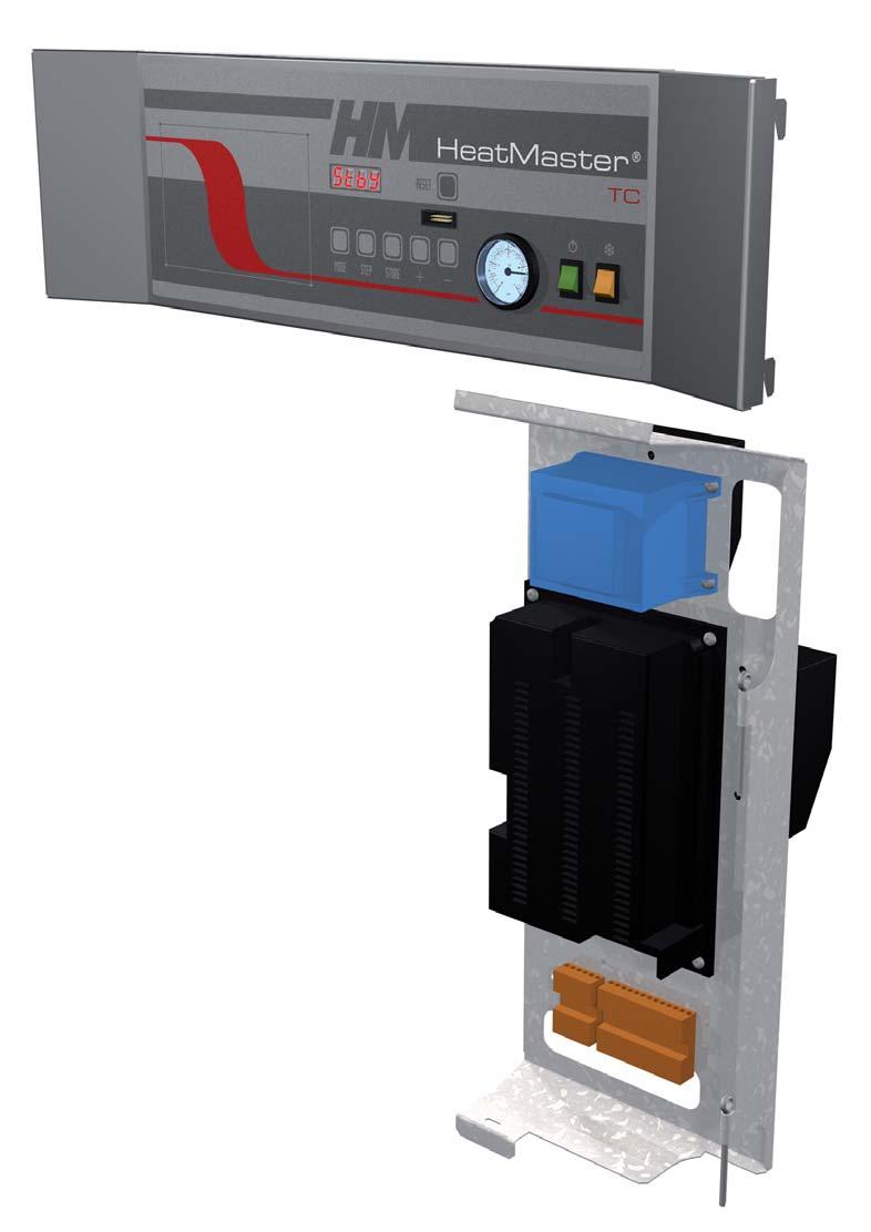
5 INTRODUCTION HeatMaster 35 TC 1. Flue connection concentric Ø 80/125 mm convertible to parallel connection Ø 80/80 mm. 2. Domestic hot water outlet 3. Heating flow 4. Stainless steel heat exchanger ENGLISH Stainless steel Tank-in-Tank hot water store 6. Indirect water preheater 7. Heating return 8. Cold water inlet 9. Condenstrap 10. Modulating premix gas burner 11. Gas connection 12. Combustion chamber 13. Control panel 14. Primary heating circuit 15. Polyurethane foam insulation oiler shunt pump 17. Separation plate 18. Primary safety valve (3 bar) 19. Drain cock HeatMaster 85 TC Flue connection concentric Ø 100/150 mm convertible to parallel connection Ø 100/100 mm 2. Domestic hot water outlet 3. Heating flow 4. Combustion chamber 5. Stainless steel heat exchanger 6. Stainless steel Tank-in-Tank hot water store 7. Auxiliary tank primary return 8. Indirect water preheater Heating return 10. Cold water inlet 11. Separation plate Gas connection 13. Modulating premix gas burner 14. Control panel 15. Primary heating circuit 16. Primary expansion vessel (2x) 17. Polyurethane foam insulation 18. oiler shunt pump Primary safety valve (3 bar) EN 5
6 ENGLISH INTRODUCTION DESCRIPTION OF THE SPECIFICATIONS The HeatMaster TC is an hot water producer combined in a condensing boiler in accordance to the elgium "HR-Top" standard. The boiler is certified compliant with "CE" standards as a connected appliance C13(x) - C33(x) - C43(x) - C53 - C83(x), but it can also be connected as an open appliance in category 23 or as an appliance of category 23P, which can operate with a positive pressure. Lining The boiler is protected by a steel lining that first of all undergoes a degreasing and phosphation process before being lacquered and heated at 220 C. The inside of this lining is coated with a layer of thermal and acoustic insulation, reducing losses to a minimum. Heat exchanger The core of the HeatMaster TC features a new stainless steel heat exchanger. This piece of technology represents the fruit of exhaustive research and intensive laboratory testing. It reflects ACV s eighty years of experience in using stainless steel for heating and hot water functions. The particular geometry of the exchanger pipes is calculated to obtain a very large Reynolds number throughout its cycles. The HeatMaster TC achieves an exceptional output that remains stable throughout the boiler s life, given that it causes no oxidation on the exchanger, which is manufactured entirely from quality steel. urner ACV uses its G 2000-M burner for the HeatMaster TC: this is an air/gas premix burner providing safe and silent operation while limiting emissions (NOx and CO) to an incredibly low level. Although the ACV G 2000-M boiler is very modern, it uses proven technology and is manufactured from standard spare parts that are easily available on the market. Temperature regulation The basic version of the HeatMaster TC is fitted with a microprocessor controlled regulator (MCA) which takes over both the safety functions (ignition, monitoring the flame, limiting the temperature, etc.) and control of the boiler temperature. This MCA also includes a weather-dependent regulator. All you need to do is connect the outdoor temperature sensor available as an option to the device. However, this regulator can also operate with a standard ON/OFF room thermostat In addition, with the combination of a weather-dependent regulator and a room thermostat, you can control the temperatures based on the weather with compensation for the indoor temperature. There are four user adjustable parameters. y entering a special maintenance code, qualified installers can access several other parameters to adapt the boiler to special requirements. In principle, these parameters are factory set for all normal applications. PRODUCTION OF HOT WATER In addition to its exceptional hot water performances, the ACV Tank-in-Tank concept provides the follwoing advantages : - A solution for scale deposits: thanks to the specially designed corrugations, the hot water tank expands and contracts during the heating cycle, preventing the formation of scale. - A guarantee against the risk of Legionnellae Disease and bacteria: the hot water tank is fully immersed in the primary circuit and the hot water is constantly kept at a temperature above 60 C. - Exceptional resistance against corrosion and aggression: provided by the stainless steel. FROST PROTECTION The boiler is equipped with an integrated frost protection: as soon as the boiler temperature drops below 7 C, the system activates the central heating pump. As soon as the NTC1 flow temperature drops below 3 C, the system automatically ignites the burner until the temperature rises above 10 C. The pump continues to run for about 10 minutes. If an outdoor temperature sensor is connected to the system, the pump is activated as soon as the outside temperature drops below the specified threshold. To provide efficient protection for the whole system against frost, all the valves on the radiators and the convectors should be completely open. EN 6
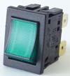
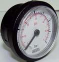
7 DIRECTIONS FOR USE Your system must be checked once a year by an approved installer or maintenance company. Starting the burner During operation, the burner starts automatically as soon as the boiler temperature drops under the required set point and it stops as soon as the boiler reaches that temperature. Control panel Pre-cut for an optional Control Unit controller MCA display Pressure gauge ON/OFF switch Summer/Winter switch Heating system The central heating circuit must be pressurized (see in the chapter Installation how to define the system pressure). The pressure indicator is located on the right-hand side of the display. If your system needs to be refilled more than twice a year, please contact your installer. The CH pressure must be a minimum of 1 bar and must be checked by the end user on a regular basis. If the pressure drops under 0.5 bar, the integrated water pressure switch blocks the appliance until the pressure in the system returns to a level above 0.8 bar. The connection for a fill valve is provided underneath the appliance. The installer can also fit the system with a separate valve. Make sure that the appliance is powered off when filling the system. To do this, toggle the Start/Stop switch located on the left of the screen to Off. (see the Control panel). For more information, please ask your installer when the system is delivered. A safety valve is provided at the underneath of the appliance. If the system pressure exceeds 3 bars, this valve opens and drains the water from the system. In this case, please contact your installer. 1 O 2 bar 3 4 SETTINGS PARAMETERS USERS GUIDE Setting the domestic hot water temperature: (Hot water temperature) - Press Mode: The screen displays PARA. - Press Step: the first character is 1 and the last two characters give the current hot water temperature setting. - To change this temperature, press + or - until the last two digits show the desired temperature value. - Press Store to save the new temperature setting. - Press Mode twice to return to Pilot mode (normal operating mode). Enabling or disabling the hot water heating mode: (hot water) - Press Mode: The screen displays PARA. - Press Step twice: the first character is 2 and the last two characters give the current setting: 00 = disabled; 01 = enabled. - To change this parameter, press + or - until the screen displays the desired value: 00 = disabled; 01 = enabled. - Press Store to save. - Press Mode twice to return to Pilot mode (normal operating mode). Enabling or disabling Central Heating mode: (heating) - Press Mode: The screen displays PARA. - Press Step three times: the first character is 3 and the last two characters give the current setting: 00 = disabled; 01 = enabled. - To change this parameter, press + or - until the screen displays the desired value: 00 = disabled; 01 = enabled. - Press Store to save. - Press Mode twice to return to Pilot mode (normal operating mode). Setting the central heating temperature: (maximum temperature for the heating circuit) - Press Mode: The screen displays PARA. - Press Step four times: the first character is 4 and the last two characters give the current central heating temperature setting. - To change this temperature, press + or - until the last two digits show the desired temperature value. - Press Store to save the new temperature setting. - Press Mode twice to return to Pilot mode (normal operating mode). Fault: The temperature setting for the appliance and the safety functions for its various parts are continuously monitored by a regulator controlled by a microprocessor (the MCA). In the event of a fault, this MCA disables the appliance and displays an error code: the screen flashes displaying E as the first character, followed by the error code. To reset the appliance: - Press "Reset" on the screen. - Contact your installer of the fault happens again. ENGLISH EN 7
8 ENGLISH TECHNICAL CHARACTERISTICS HeatMaster 35 TC HeatMaster 85 TC Central heating Natural gas Propane Natural gas Propane Max. Input 80/60 C kw 34,9 30,6 85,0 [92,0] 85,0 [92,0] Min. Input 80/60 C kw 10,0 10,0 17,2 17,2 Max. output 80/60 C kw 34,1 29,9 82,5 82,5 Min. output 80/60 C kw 9,8 9,8 16,7 16,7 Effi ciency 30% load [EN677] % 108,5 108,5 107,8 107,8 Effi ciency domestic hot water mode [Δt = 30 C] % 105,9 105,9 104,0 104,0 Flue gases CO emissions max. / min. Input mg/kwh 70 / / 17 58,9 / 4,3 90,0 / 45,0 NOx emissions max. / min. Input mg/kwh 59 / / 31 72,4 / / 27 NOx classifi cation [EN483] Flue gas temperature max. Input 80/60 C C ,6 61,6 Flue gas temperature max. Input 50/30 C C ,1 35,1 Mass fl ow rate of combustion products kg/h 55 46,5 137 [148] 134 [145] Flue gas pipe - Max. pressure drop Pa Concentric fl ue gas channel maximum length m Gas Gas pressure mbar 20 / / 37 / / / 37 / 50 G20 gas fl ow rate m 3 /h 3,7 8,99 [9,73] G25 gas fl ow rate m 3 /h 4,3 10,46 [11,32] G31 gas fl ow rate m 3 /h 1,25 1,25 CO 2 max. Input % CO 2 9,4 10,5 9,3 10,9 CO 2 min. Input % CO 2 9,0 10,1 8,6 9,0 Hydraulic parameters Max. operating temperature C Total capacity L Heating circuit capacity L 108,5 108, Maximum operating pressure central heating bar Heat exchanger pressure drop [ΔT = 20 C] mbar Electrical connection Class IP Supply voltage V/Hz 230/50 230/50 230/50 230/50 Maximum absorbed electrical power A 0,8 0,8 1,0 1,0 Weight empty kg [ ] = Domestic hot water mode EN 8
9 I2E(S) * I2E(R) ** TECHNICAL CHARACTERISTICS Gas categories HeatMaster 35 / 85 TC II2H3/P II2H3P II2E3/P II2Er3P II2L3/P II2L3P I3P ENGLISH G20 20 mbar 20 mbar 20 mbar 20 mbar 20 mbar G25 25 mbar 25 mbar 25 mbar 25 mbar E CH G mbar mbar mbar G mbar mbar mbar mbar mbar mbar 37 mbar elgium Switzerland CZ Czech republic DE DK EE ES FR Germany Denmark Estonia Spain France G Great ritain GR IE IT LU Greece Ireland Italy Luxembourg LT Lithuania NL Netherlands PL PT SI Poland Portugal Slovenia SK Slovakia SE Sweden (*) HeatMaster 35 TC (**) HeatMaster 85 TC EN 9
10 ENGLISH TECHNICAL CHARACTERISTICS MAXIMUM OPERATING CONDITIONS Maximum service pressure (tank full of water) - Primary circuit : 3 bar - Secondary circuit : 10 bar Maximum operting temperature : 90 C Water quality: - Chlorures : < 150 mg/l - 6 PH 8 DOMESTIC HOT WATER FEATURES Operating conditions at 90 C HeatMaster 35 TC HeatMaster 85 TC Peak fl ow at 40 C [ΔT = 30 C] L/ Peak fl ow at 40 C [ΔT = 30 C] L/ Constant fl ow at 40 C [ΔT = 30 C] L/h Peak fl ow at 45 C [ΔT = 35 C] L/ Peak fl ow at 45 C [ΔT = 35 C] L/ Constant fl ow at 45 C [ΔT = 35 C] L/h Peak fl ow at 60 C [ΔT = 50 C] L/ Peak fl ow at 60 C [ΔT = 50 C] L/ Constant fl ow at 60 C [ΔT = 50 C] L/h Pre-heat time minutes EN 10
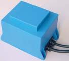
11 WIRING DIAGRAM : HeatMaster TC ELECTRICAL CONNECTION ENGLISH 1. Power supply 230 V 2. ON/OFF switch 3. oiler shunt pump 4. Heating pump (optional) 5. Gas valve rectifier Volt - 24Volt transformer 7. MCA 8. Display 9. Water pressure switch 10. Fan PWM control 11. Summer/Winter switch 12. NTC1 flow sensor 13. NTC2 return sensor 14. NTC5 flue gas temperature 15. Room thermostat (optional) 16. NTC3 domestic hot 17. NTC4 outdoor temperature (optional) 18. NTC6 second heating circuit flow sensor (optional) 19. Zero volt of 24V circuit. 20. Safety contact thermostat RAM (optional) 21. Ionisation and ignition cable 22. urner power supply 230 V (only HeatMaster 85 TC] 23. Gas pressure switch HeatMaster 85 TC X US A US t. lue k. lack r. rown G. Grey Or. Orange R. Red V. Violet W. White Y/Gr. Yellow/Green r W R G r k R r k Or G V V G 9 P V 23 P Or 11 k R k r Or k R r R r Or k k R V W R Or V X5.1 X5.2 X5.3 X5.4 X4.1 X4.2 X4.3 X3.1 X3.2 X3.3 X3.4 X3.5 X3.6 X2.1 X2.2 X2.3 X2.4 X2.5 X2.6 X2.7 X2.8 7 X R R X2.9 G G X M 230V Y/Gr r PE N L X12. r Y/Gr W Y/Gr r Y/Gr 3 M PE N L1 2 r r Y/Gr W V r X2.11 X2.12 X1.6 X1.5 X1.4 X1.3 X1.2 X1.1 X10.7 X10.6 X10.1 X10.3 r Y/Gr k R r 6 22 EN 11

12 2 1 bar O bar O 3 4 ENGLISH INSTALLATION INSTRUCTIONS DIMENSIONS A mm mm C mm D mm E mm F mm G mm HM 35 TC HM 85 TC H mm I mm J mm K mm L mm M mm N mm O mm HYDRAULIC CONNECTIONS HeatMaster 35 TC HeatMaster 85 TC Heating connection [F] Ø 1" 1"1/2 Domestic hot water connection [M] Ø 1" 1"1/2 Gas connection [M] Ø 3/4" 3/4" C E D F H I x 65 Kit Easy Fit only for HeatMaster 35 TC J A G M K L 1736 N O OILER ROOM - Make sure that all air vents are unobstructed any times. - Do not store any flammable products in the boiler room. - Do not store any corrosive products, paint, solvents, salts, chlorine products and other detergent products near the appliance. - If you smell gas, do not switch on any lights, turn off the gas tap at the meter, ventilate the rooms and contact your installer. Min. 25 mm Min. 300 mm Min. 25 mm ACCESSIILITY The appliance must be positioned in such a way to be accessible any time. In addition, the following distances are required around the appliance. EN 12
13 2 1 bar 3 O 4 CONNECTION TO THE CHIMNEY - The chimney connections must comply with the applicable standards (in elgium: NN D51-003), the local energy supplier s instructions, the fire regulation and neighbourhood good practices. - The HeatMaster TC has an inbuilt gas/air ratio regulator, which makes it largely independent of the pressure drop in the air intake and flue gas extraction system. However, the maximum pressure drop for this system may not be exceeded, or the pressure will diminish. Nevertheless, the gas/air ratio regulator continuously guarantees optimum combustion with very low emission levels. - The horizontal flue gas pipes must always be installed with a min. slope of 5 mm per meter, upwards from the boiler side. - There must be no obstruction or openings for any other appliances within a radius of 0.5 metres around the flue terminal of the HeatMaster TC. - The maximum flue resistance is 130 Pascal for the HeatMaster 35 TC and 150 Pascal for the HeatMaster 85 TC. You can use the following table as the basis for calculating this value (please also refer to the specimen calculation presented under the table). Sample calculation: The diagram below consists of the following parts: pipe with monitoring section + 2 * 90 pipe bends + 2 metres of horizontal pipe + 2 * 45 pipe bends + ( ) metres of vertical pipe and fall back + discharge. Therefore, the resistance of this system is as follows: (2 x 6.0) + (2 x 5.0) + (2 x 4.0) + (4 x 5.0) + 20 = 72.5 Pa. This value is less than the maximum authorised resistance, therefore the installation is compliant. Table of flue resistance in Pascal (1 Pascal = 0,01 mbar) 1 m straight pipe Pipe with a monitoring section Pipe concentric HM 35 TC Ø 80/125 mm INSTALLATION HM 85 TC Ø 100/150 mm 2000 mm Air inlet separate HM 35 TC Ø 80 mm 1000 mm HM 85 TC Ø 100 MM 2000 mm Air extraction separate HM 35 TC Ø 80 mm 1000 mm HM 85 TC Ø 100 mm , , , , ,7 90 pipe bend , , ,3 45 pipe bend , , ,3 Vertical pipe ,5 Horizontal pipe ,9 This table is based on the equipment offered by ACV and cannot be applied generally. ENGLISH EN 13
14 2 1 bar 3 O bar 3 O bar 3 O bar 3 O bar 3 O bar 3 O bar 3 O bar 3 O 4 ENGLISH INSTALLATION Options for connection to the chimney 23P C43 C33 C53 23 C43 C33s C13 23 : Connection to an exhaust duct venting the combustion products outside of the installation area, with the combustion air being drawn directly from this area. 23P : Connection to an exhaust system of the combustion products designed to operate with positive pressure. C13 C33 : Connection by pipes with horizontal terminal units that simultaneously intake the combustion air and discharge the combustion products outside through openings that are either concentric or close enough together to be subjected to similar wind conditions. : Connection by pipes with vertical terminal units that simultaneously intake fresh air and discharge the combustion products outside through openings that are either concentric or close enough together to be subjected to similar wind conditions. EN 14 C33s : Connection with an individual system of which the exhaust duct for the combustion products is installed in an exhaust pipe that is part of the building. The appliance, the exhaust duct and the terminal units are certified as an assembly that cannot be dissociated. C43 C53 : Connection by two ducts to a collective duct system serving more than one appliance; this system of collective ducts features two ducts connected to a terminal unit that simultaneously intakes fresh combustion air and discharges the combustion products outside through openings that are either concentric or close enough together to be subjected to similar wind conditions. : Connection to separate ducts for the supply of combustion air and for venting the combustion products; these ducts may end in zones with different pressure levels.
15 2 1 bar O 3 4 CONNECTION TO THE GAS - The HeatMaster TC is fitted with a Ø 3/4 male fitting connector, on which you can connect the gas tap. - The gas connection must comply with the applicable regulations (e.g. NN D in elgium) in the country of installation. - Where there is a risk of dirt stemming from the network, place a gas filter upstream from the connection. INSTALLATION - Drain the gas pipe and check in minute detail that all the boiler pipes, both inside and outside, are sealed. - Check the gas pressure in the system. Consult the technical characteristics. - Check the gas pressure and consumption when commissioning the appliance. ENGLISH DOMESTIC HOT WATER CONNECTION 7 6 efore pressurising the central heating circuit (primary) you should first pressurise the domestic hot water tank (secondary). The HeatMaster TC boiler can be connected directly on the domestic hot water circuit. Flush out the system before connecting the domestic hot water part. The installation must be fitted with an approved safety unit with a 7-bar safety valve, a non-return valve and a shut-off valve. During the heating process, the domestic hot water dilates and the pressure increases. As soon as the pressure exceeds the safety valve setting, the valve opens and discharges a small quantity of water. Using a hot water expansion vessel (2 litres at least) will prevent this phenomenon and reduce water hammer effect. The hot water output temperature may reach temperatures in excess of 60 C, which can cause burns. We therefore recommend that that you install a thermostatic mixer immediately after installing the appliance. If stop valves are used in the domestic hot water system, they can cause pressure waves when closed. Use devices designed to reduce water hammer to avoid this phenomenon Cold water supply tap 2. Non-return valve 3. Pressure reducing valve 4. Safety group 5. Hot water expansion vessel 6. Thermostatic mixer 7. Drawoff tap If the HeatMaster 35 TC is used as a DHW- boiler without connection to heating circuit, an external primary expansion vessel of minimum 16 litres should be installed in the system (no internal expansion vessel on HeatMaster 35 TC). EN 15
16 2 1 bar O 3 4 ENGLISH INSTALLATION HEATING CONNECTIONS Recommendations efore pressurising the central heating circuit (primary) you should first pressurise the domestic hot water tank (secondary). HEATING CONNECTIONS : GENERAL 1. Isolating valve, heating system 2. Internal primary safety valve calibrated to 3 bar 3. System filling valve 4. Expansion vessel 5. Drain cock 6. Condenstrap 7. Heating pump - The central heating system must be completely flushed out with tap water before connecting the boiler. - The central heating safety valve is incorporated under the appliance and must be routed to the drain with an open connection (to allow inspection). - Two primary expansion vessels of 10 litres are integrated in the HeatMaster 85 TC (none in the HeatMaster 35 TC). In function of the installation, an external expansion vessel has to be installed A temperature homogeneisation pump fits the boiler. That pump runs aswell during hot water mode aswell in heating mode. The speed selection of the pump must be set to 3. - Fill the system with fresh water. Contact your ACV representative about the use of inhibitors. - It is possible that the pumps are locked due to the presence of residual water from tests completed on the appliance. Therefore, we recommend that you unblock the pumps before filling the appliance. - You will find the connection for the filling valve and/or drainage valve on the bottom of the appliance. Fill the appliance to a minimum pressure of one bar. Drain the whole system and re-fill the appliance to a pressure of 1,5 bar Fit the condenstrap, fill it with tap water and connect the hose to the drain using a connection with an inspection section. Make sure you prevent the freezing of the condensates. The condense water-trap must be connection to the drainage system in accordance with current standards in force. ASSEMLING THE ALL CONDENSATE TRAP If there is a risk of low pressure in the hot water circuit (installation of HeatMaster on the roof of a building), it is essential to install a vacuum breaker device onto the cold water supply. EN 16
17 INSTALLATION OF A SINGLE HIGH TEMPERATURE CIRCUIT WITH ROOM THERMOSTAT ACV 15 CONTROL General diagram The On/Off room thermostat controls the central heating system (radiators only). The pump is powered as soon as the room thermostat generates an heat demand. Advantages for the user: - Simplicity of the system - Direct connecton to existing installations Remove this shunt before connectiong a room thermostat Factory setting Typical setting ACV 15 Optional accessories Code Description Room themostat ACV [HM 35 TC] [HM 85 TC] Description INSTALLATION High temperature kit DN 20 Including: one circulation pump, two isolating valves, check valve, two thermometers High temperature kit DN 32 Including: one circulation pump, two isolating valves, check valve, two thermometers MCA ENGLISH 00 : Heating mode OFF 01 : Heating mode ON Setting temperature for the heating water (adjustable between 30 and 85 C). 00 : Using a outside temperature sensor and a room thermostat EN 17

18 ENGLISH INSTALLATION INSTALLATION OF A WEATHER DEPENDING HEATING CIRCUIT HIGH OR LOW TEMPERATURE General diagram This is a simple way to control two heating circuits (radiators or floor heating) with weather depending control. Advantages for the user: - Comfort - Efficiency ACV 15 AF120 SQK 349 AM3-11 MCA NTC12K RAM Optional accessories Code Description Code Description Room themostat ACV AM3-11 module Controls the second heating circuit - communicates directly with the MCA [HM 35 TC] Outside temperature sensor 12kΩ AF120 Low temperature kit DN 20 Including: one circulation pump, two isolating valves, check valve, two thermometers, the 3-way valve with integrated bypass. 537D3040 Contact sensor 12kΩ To be mounted on the outlet of controlled circuit [HM 85 TC] Low temperature kit DN 32 Including: one circulation pump, two isolating valves, check valve, two thermometers, the 3-way valve with integrated bypass Contact thermostat RAM 5109 Required to protect all fl oor heating circuits Servomotor SQK 349 Electromechanical servomotor SQK 349 for the three-way valve included in low temperature kit (opening times : 150 seconds) EN 18
 P39 P40 90 80 70 60 50 40 30 20 10 0-25 -20-15 -10-5 0 5 10 15 20 25 P6 P7 Outside T (")
 Minimum outside temperature [T4] (adjustable between -20 and 10 C).")
19 To be wired in accordance with the applicable regulations. Y1 X3 INSTALLATION ENGLISH Ph Y2 X2 N X1 N N PE 1 2 L1 L T departure boiler ( C) P39 P P6 P7 Outside T ( C) Factory setting Typical setting Maximum setpoint in domestic hot water mode 00 : Domestic hot water mode OFF 01 : Domestic hot water mode ON Description 00 : Heating mode OFF 01 : Heating mode ON Maximum temperature of the heating circuit (must be higher than hot water setpoint) Minimum outside temperature [T4] (adjustable between -20 and 10 C). Maximum outside temperature [T4] (adjustable between 15 and 25 C). 10 : Heating pump controlled by room thermostat - hot water priority active 21 : Heating pump runs continuously - hot water priority active 50 : Heating pump controlled by room thermostat - hot water priority not active 61 : Heating pump runs continuously - hot water priority not active Maximum temperature of the heating circuit Minimum temperature of the heating circuit EN 19
20 ENGLISH INSTALLATION INSTALLATION OF TWO HEATING CIRCUIT CONTROLLED Y ROOM UNIT AND ZMC-1 MODULE General diagram This configuration controls two heating circuits (radiators or floor heating). In addition, the Room unit features a remote monitoring of the two circuits You can adjust those two circuits depending on the outside temperature. This is the ideal configuration for floor heating with additional heating provided by radiators. You can select various heating functions, and program up to three weekly schedules, as well for the central heating as for the hot water production. Room Unit AF120 SQK 349 SQK 349 ZMC1 VF202 RAM VF202 ZMC1 MCA Optional accessories Code Description Code Description X2 Room Unit RSC Supplied with outside temperature sensor ZMC-1 module (kit) Controls the second heating circuit - alarm contact - operates only in conjonction with the Room Unit RSC [HM 35 TC] [HM 35 TC] X2 Collector 2 circuits DN 20 With bypass, connecting tubes and integrated wall brackets Low temperature kit DN 20 Including: one circulation pump, two isolating valves, check valve, two thermometers, the 3-way valve with integrated bypass X2 Clip-in interface RMCIEV3 Enables communications between the MCA and the Room Unit RSC. Contact sensor 2kΩ VF202 To be mounted on the outlet of controlled circuit [HM 85 TC [HM 85 TC] Collector 2 circuits DN 32 With integrated wall brackets Connection kit DN 32 to the manifold Including: Two fl exible 1"1/2 hoses and 1"1/4 reduction fi ttings Contact thermostat RAM 5109 Required to protect all fl oor heating circuits [HM 85 TC X2] Low temperature kit DN 32 Including: one circulation pump, two isolating valves, check valve, two thermometers, the 3-way valve with integrated bypass Outside temperature sensor 12kΩ AF X2 Servomotor SQK 349 Electromechanical servomotor SQK 349 for the three-way valve included in low temperature kit (opening times : 150 seconds) EN 20

21 Ph N To be wired in accordance with the applicable regulations. Y1 Y2 N N INSTALLATION A ENGLISH PE AV MPK ZU AUF ZMC1 N Y1 Y2 N 0 24V A VF VE A AV MPK ZU AUF ZMC1 1 2 A V A VF VE : Interface address 0 = 0 = 4 = 1 = 5 = 2 = 6 = 3 = 7 Factory setting Typical setting Description Maximum setpoint in domestic hot water mode 00 : Domestic hot water mode OFF 01 : Domestic hot water mode ON 00 : Heating mode OFF 01 : Heating mode ON Maximum temperature of the heating circuit (must be higher than hot water setpoint) EN 21

22 ENGLISH COMMISSIONING AND MAINTENANCE COMMISSIONING THE SYSTEM efore pressurising the central heating circuit (primary) you should first pressurise the domestic hot water tank (secondary). oth the domestic hot water tank and the central heating circuit must be filled before using the boiler. - Slowly fill the tank and drain it by opening a hot water tap. Drain all the taps and check that there are no leaks in the domestic hot water system. - Fill the whole system up to a minimum pressure of 1 bar (preferably 1.5 bar), using the boiler s fill valve. Fill the system slowly. Also check that the automatic air vent on the tank is working. Check that there are no leaks in the central heating system. - Vent the shunt pump and unblock it if necessary. - Open the gas tap, drain the pipe and check that there are no leaks in the system. - Place the condensing trap on the bottom face of the boiler and check it is fill with water. - Connect the plug to the wall socket and power on the appliance. If needed, place the room thermostat to its highest position. The boiler should start. Check the gas pressure and allow the boiler to heat up for a few minutes. Set the boiler to High Power mode and check the CO2 level (see the table of Technical Characteristics). Then, set the boiler to Low Power mode and check the CO2 level again (see the table of Technical Characteristics). - Set the central heating and hot water temperatures following the values given in the Directions for Use. - Drain the central heating system again and, if necessary, re-fill it. - Make sure the central heating system is correctly balanced and, if necessary, adjust the valves to prevent a greater or lesser flow than planned to some circuits or radiators. The condensate flow pipe diameter can not be decreased. Moreover this pipe can never be blocked. CHECKING THE SETTING - Check that the parameters are set in accordance with the user s needs: see page 3, Directions for Use. - Check the boiler settings: this task can only be carried out by an ACV-trained installer or by the ACV maintenance department. - Set the appliance to High Power mode by simultaneously pressing the mode and Plus keys. 2 3 Réf. 3: The gas valve offset setting is a sealed factory setting. In principle, it may not be modified. - Check the dynamic gas pressure at the gas valve (see diagram below, ref. 1). This must be at least 18 mbars. Wait a few minutes for the appliance to heat up to a minimum temperature of 60 C. Check the CO2 setting using a measurement instrument. Please see in the Technical Characteristics for optimum value. To increase the CO2 value, turn the venturi screw counterclockwise; turn it clockwise to reduce the value (see diagram below ref. 2). Then put the appliance to High Power mode by simultaneously pressing the mode and Plus keys. Wait a few minutes to stabilise. Check the CO2 value. It should be either equal to the full power value or a maximum of 0.5% less than this value. If you record a significant deviation,please contact the ACV maintenance department. INSPECTION AND MAINTENANCE ACV recommends that you have your boilers inspected and cleaned if need be at least once a year. Plug out the appliance before undertaking any work, even if only recording measurements and adjusting the settings. - Check that the condenstrap is not fouled, fill it, if need be, and check that there are no leaks. - Check that the safety valves are operating correctly. - Drain the whole system and if necessary re-fill the appliance to pressure of 1.5 bar. If you have to refill your circuit more than twice a year, please contact your installer. - Check the boiler charge in High Power mode. If there is a big difference between this value and the original setting, the deviation could mean a blockage in the air intake pipes or flue gas extraction pipes, or that the exchanger has become fouled with an accumulation of dirt. TEMPERATURE SENSOR RESISTANCE TALES T [ C] R Ω T [ C] R Ω T [ C] R Ω EN 22
, the ignition cable, the gas valve control and the ignition electrode earth. - Loosen the 4 burner nuts using a ratchet wrench.")
23 DISASSEMLING THE URNER - Close the inlet gas valve. - Remove the top front panel of the boiler. - Unplug the fan plugs (24 Volt), the ignition cable, the gas valve control and the ignition electrode earth. - Loosen the 4 burner nuts using a ratchet wrench. - Unscrew the three-way coupling on the gas pipe. - In one unit, lift up the burner with the fan and the gas valve to remove them from the exchanger. e careful not to damage the burner insulation in the exchanger. - Check the condition of the insulation and the seals and replace them if necessary before re-assembling the burner following the same procedure but in the reverse order. COMMISSIONING AND MAINTENANCE CLEANING THE HEAT EXCHANGER - Remove the burner assembly as described above. - Remove the burner gasket. - Clean the combustion chamber using a vacuum cleaner. - It could be necessary to clean the flue tubes by putting water in the combustion room. After that operation, it is necessary to clean the condensing trap. - Check the burner insulation and the burner gasket; replace the parts if necessary. - Check the igniter, replace if necessary - Reassemble the burner and check for leakages. - Power up the appliance, set the boiler in full power mode and recheck for leaks. - Check the gas pressure and the CO2 level as explained in previous paragraf. ENGLISH X 4 DISASSEMLING AND CHECKING THE ELECTRODE - Remove the ignition cable. - Remove the two fixing screws. - Remove the electrode earth but make sure the serrated washer is fixed between the earth cable and the electrode when re-assembling. - Check the condition of the seals and replace them if necessary before re-assembling the electrode following the same procedure but in the reverse order. HeatMaster 35 TC 3 5 HeatMaster 85 TC EN 23
24 ENGLISH MCA PARAMETERS FOR THE SPECIALIST STANDY MODE Standby Mode After you power down the appliance the screen displays Pilot mode, as shown in the figure above. Once the cause of the blockage has been resolved, the burner starts automatically within 150 seconds at most. Status oiler function Internal check three-way valve This is the standard MCA mode. The MCA automatically returns to this mode after 20 minutes if no keys have been pressed on the screen. Any parameters that were modified are then enabled. The first character shows the current status of the boiler depending on the condition of both the boiler and the burner. The last 2 characters indicate the start temperature. Status oiler function oiler burner in hot water ready function Test function: Central heating high power Test function: Central heating low power Test function: oiler with fixed number of revolutions Standby, no demand for heat Fan first, fan after Ignition Operation of the boiler burner for the heating Operation of the boiler burner for the domestic hot water Air pressure limit or obtaining the number of start revolutions The burner goes out when the specified value is reached. A demand for heat is present nonetheless. Pump over-run time after the demand for central heating Pump over-run time after the demand for domestic hot water urner blocked: If the burner is blocked for one of the reasons mentioned above, the screen display alternates between a 9 followed by the temperature (two last digits) and b with the error code. : T1 > 95 C : T2 > 95 C : T2 - T1 > 10 C after 90 seconds : dt1/dt > maximum gradient T1 : water pressure switch not off : no fan signal : erroneous fan signal : T1 - T2 > Δ max. : NTC3 short-circuit : NTC5 short-circuit : NTC3 interrupt : NTC5 interrupt : T5 > T5 max : wait for the fan to start EN 24
25 SETTING THE MCA PARAMETERS Parameter Mode MCA PARAMETERS FOR THE SPECIALIST ENGLISH To access Parameter mode when the system is in Pilot mode, press MODE once. To scroll through the list of parameters, simply press step. To modify a parameter value, use the + or - keys. Then press Store to save the value you just changed. The screen flashes once to confirm the data has been saved. To activate the parameters you changed, press MODE once more (which brings you into Info mode). However, if you do not press a key, the system returns to Pilot mode after 20 minutes and automatically enables the changes. Key Screen MODE Key Screen Description of parameters HeatMaster 35 TC Factory setting HeatMaster 85 TC Adjusting the hot water temperature Production of hot water 00 = Stop 01 = Start Turn On/ Turn Off the heating 00 = Stop 01 = Start Maximum temperature in Central Heating mode EN 25
26 ENGLISH MCA PARAMETERS FOR THE SPECIALIST REQUEST FOR INFORMATION ON THE INSTALLATION Info Mode To switch from Standby to Info mode, press Mode twice. ENTERING THE CODE Code Mode You can access the following parameters by entering the service code: Key MODE MODE Screen Press until the system displays the information you need. The point located behind the first position flashes to indicate that the boiler is in INFO mode. Parameters 5-42 Communication mode Fan Speed mode ERROR mode To access Code mode, press MODE and simultaneously [only from Standby mode!]. Key Screen Description of parameters oiler temperature T1 [Top of the primary] oiler temperature T2 [Top of the primary] MODE Press once and the system displays C in position 1, followed by arbitrary characters in positions 3 and 4. Hot water temperature T3 in C [ottom of the hot water tank] Outdoor temperature T4 in C Flue gas temperature Press + or - to change the code. + or - Calculated boiler temperature in C Press STORE, the screen flashes briefly to indicate that the code has been accepted. Rate of increase of T1 temperature in C/s Rate of increase of T2 temperature in C/s STORE Press MODE until the system displays the correct mode. Rate of increase in the hot water temperature in C/s Flow temparature of the heating circuit (with module AM3-11 only) Only ACV authorised installers know the access code. For further information, please contact our after-sales department. EN 26
27 MCA PARAMETERS FOR THE SPECIALIST MCA PARAMETERS WITH CODE RESTRICTED ACCESS Factory setting Key Screen Description of parameters HM 35 TC HM 85 TC ENGLISH Minimum temperature of the top part of the boiler in heating mode when using an outdoor sensor In order to avoid cycling between heating and hot water mode, it is preferable to set that parameter higher than DHW set point [Para 1] Minimum outdoor temperature [adjust the heating curve] Maximum outdoor temperature [adjust the heating curve] Frost protection temperature Correction of outdoor temperature lockage T 0 = Disabled Acceleration time lag 00 = Stop [minute] Night reduction heating ( C) Maximum number of fan revolutions in CH mode [rpm x 100] Natural gas Propane Maximum number of fan revolutions in CH mode [rpm /min.] Max. number of revs in domestic hot water mode [rpm x 100] Maximum number of fan revolutions in domestic hot water mode [rpm] Natural gas Propane Natural gas Propane Natural gas Propane Minimum number of fan revolutions [rpm x 100] Natural gas Propane EN 27
28 ENGLISH MCA PARAMETERS FOR THE SPECIALIST Factory setting Key Screen Description of parameters HM 35 TC HM 85 TC Gaz naturel Minimum number of fan revolutions [rpm] Propane Number of fan revolutions at ignition [rpm x 100] CH pump over-run 0 = 10 sec. [step = 1 minute] Gaz naturel Propane Domestic hot water pump over-run time [step = 10.2 sec] Central Heating modulation hysteresis enabled Central Heating modulation hysteresis disabled Domestic hot water modulation hysteresis enabled Domestic hot water modulation hysteresis disabled Detection of domestic hot water hysteresis enabled Detection of domestic hot water hysteresis disabled Central Heating blockage time [sec. x 10,2] Domestic hot water blockage time [sec. x 10,2] Domestic hot water Central Heating blockage time [sec. x 10,2] EN 28
29 MCA PARAMETERS FOR THE SPECIALIST Factory setting Key Screen Description of parameters HM 35 TC HM 85 TC ENGLISH Re-modulate the difference T1 - T2 us address [-1 = disabled] Temperature increase set point for the production of hot water 00 : High temperature circuit - heating pump controlled by room thermostat - hot water priority active 10 : Controlled circuit (outside sensor + AM3-11 module) - heating pump controlled by room thermostat - hot water priority active 21 : Controlled circuit (outside sensor + AM3-11 module) - heating pump runs continuously - night reduction possible - hot water priority active 50 : Controlled circuit (outside sensor + AM3-11 module) - heating pump controlled by room thermostat - hot water priority not active 61 : Controlled circuit (outside sensor + AM3-11 module) - heating pump runs continuously - night reduction possible - hot water priority not active Selection of the type of hot water production - That parameter is fixed in a HeatMaster TC and must not be changed Manual fan speed First position: PWM pump level during burning in, not used Second position: PWM pump level during over-run time, not used T set hold boiler warm Maximum temperature for the 2nd heating circuit Minimum temperature for the 2nd heating circuit 2nd circuit temperature hysteresis First position: Special pump [0 = disabled] Second position: Minimum disable cycle [0 = disabled] EN 29
30 ENGLISH MCA PARAMETERS FOR THE SPECIALIST COMMUNICATION MODE [with code] When in this mode, the system displays the communication between the boiler and the control module, the optional interface kit or the optional programmable room thermostat. ERROR MODE [with code] ERROR mode indicates the most recent error, as well as the status of the boiler and its readings at the time this error occurred. Key Screen Key Screen MODE Key Screen Description of parameters No communication MODE Key Screen Description of parameters Code error of the last lock-out FAN MODE [with code] Key Screen Communication between the boiler module and the optional control modules only Communication between all the devices connected Description of parameters Status of the boiler at the time of the error Temperature T1 at the time of the error Temperature T2 at the time of the error MODE Fan speed The current fan speed is rpm. Hot water temperature T3 at the time of the error Outdoor temperature T4 at the time of the error EN 30
31 SAFETY STOP [ERROR mode] MCA PARAMETERS FOR THE SPECIALIST If a fault occurs while the appliance is running, the system locks and the screen starts to flash. The first character is an E and the next two characters give the code for this fault, as illustrated in the table below. To unlock the system: Press RESET on the screen. Contact your installer if the fault happens again. ENGLISH Codes Description of the fault Resolution of the fault Abnormal flame signal No flame signal after five attempts at firing the boiler Rectifier or gas valve error - Check the wiring (short-circuit in the 24V wiring) - Check the electrode - Replace the MCA (water damage) - Check the ignition cable - Check the electrode and the position of the electrode - Check that there is gas at the burner. Replace the rectifier or gas valve Persistent lock Press RESET Internal error EPROM error Max input, thermostat open or 24V fuse gone. If the problem persists after two RESET attempts, replace the MCA. If the problem persists after two RESET attempts, replace the MCA. - Check the wiring - Check the 24V fuse on the MCA. - Shunt12-13 missing Internal error If the problem persists after two RESET attempts, replace the MCA. T1 > 110 C T2 > 110 C - Check the NTC wiring and replace if necessary. If NTC1 is OK, please verify that the water flows trough the boiler. - Check the NTC wiring and replace if necessary. T1 gradient too high - Check that the pump is turning. - If there is no problem with the pump, drain the system. No fan signal present The tacho signal of the blower does nt go to zero. NTC1 short-circuit - Check the fan control connection - Check the fan wiring If the problem persists after two RESET attempts, replace the MCA. - Check that the convection flow through the chimney is not high enough to rotate the blower. If not, exchange the blower. - Check the connection of the NTC1 sensor - Check the wiring of the NTC1 sensor If the problem persists, replace the NTC1 sensor NTC2 short-circuit EN 31 - Check the connection of the NTC2 sensor - Check the wiring of the NTC2 sensor If the problem persists, replace the NTC2 sensor
32 ENGLISH MCA PARAMETERS FOR THE SPECIALIST Codes Description of the fault Resolution of the fault NTC3 short-circuit - Check the connection of the NTC3 sensor - Check the wiring of the NTC3 sensor If the problem persists, replace the NTC3 sensor NTC1 connection open NTC2 connection open NTC3 connection open Internal error Flue gas temperature too high (NTC5) Error while reading the parameters Problem with the power supply to the fan - Check the connection of the NTC1 sensor - Check the wiring of the NTC1 sensor If the problem persists, replace the NTC1 sensor - Check the connection of the NTC2 sensor - Check the wiring of the NTC2 sensor If the problem persists, replace the NTC2 sensor - Check the connection of the NTC3 sensor - Check the wiring of the NTC3 sensor If the problem persists, replace the NTC3 sensor If the problem persists after two RESET attempts, replace the MCA. - Check the connection of the NTC5 sensor - Check the wiring of the NTC5 sensor If the problem persists, replace the NTC5 sensor Press RESET If the error persists, replace the MCA. - Check the MCA power supply voltage. If it is OK, replace the fan. EN 32
33

34 HeatMaster 35 TC 537D A D A F D D DZ D A D A DZ F A

35 HeatMaster 85 TC 557A D D A D D F D DZ A A DZ F A

36 HeatMaster 35 TC 5476G F A F G D D A A A G A8002

37 HeatMaster 85 TC 507F F G A DC G D A G A A A G A A8002

38 HeatMaster TC HM 35 TC : HM 85 TC : HM 35 TC : 2147C425 HM 85 TC : 2147C426 HM 35 TC : HM 85 TC : HM 35 TC : HM 85 TC : HM 35 TC : HM 85 TC : HM 35 TC : HM 85 TC : HM 35 TC : HM 85 TC : HM 35 TC : HM 85 TC : HM 35 TC : HM 85 TC :


39 HeatMaster TC D D D HM 35 TC : 5476G042 HM 85 TC : 5476G043


40 2 1 bar O 3 4 HeatMaster 35 TC - (Ø 80/125 mm) HeatMaster 35 TC A 537D D6185 C 537D6186 L. 250 mm D 537D6187 L. 500 mm E 537D6188 L mm F 537D6189 L. 325 / 400 mm G 537D H 537D I 537D6193 J 537D6192 K 537D6232 Ø 80/125 mm - 2 x Ø 80 mm L 537D6182 M 537D6194 Ø 390 mm N 537D6183 Ø 125 mm C13 M G L C33 A D H E N F C I J K


41 2 1 bar O 3 4 HeatMaster 85 TC - (Ø 100/150 mm) HeatMaster 85 TC A 537D D6198 C 537D6199 L. 250 mm D 537D6200 L. 500 mm E 537D6201 L mm F 537D6202 L. 325 / 400 mm G 537D H 537D I 537D6206 J 537D6205 K 537D6207 Ø 100/150 mm - 2 x Ø 100 mm L 537D6209 M 537D6208 Ø 430 mm N 537D6210 Ø 150 mm C13 M G L C33 A D H E N F C I J K
PrestigeMK2. Installation, Operating and Servicing Instructions. Prestige Solo Prestige AquaSpeed Prestige Excellence ENGLISH
 ENGLISH PrestigeMK2 Installation, Operating and Servicing Instructions Prestige Solo 24-32 Prestige AquaSpeed 24-32 Prestige Excellence 24-32 EN 1 ENGLISH INDEX WARNING 3 Who should read these instructions
PrestigeMK2. Installation, Operating and Servicing Instructions. Prestige Solo Prestige Excellence ENGLISH FRANCAIS NEDERLANDS ITALIANO
 PrestigeMK2 Installation, Operating and Servicing Instructions Serial number higher than 40000: please see the new MCBA parameters in "Instruction for specialist MCBA-5" Prestige Solo 24-32 Prestige Excellence
Installation, operating and maintenance instructions
 English Prestige50-75 - 120 MCA-5 Installation, operating and maintenance instructions EN 1 English INDEX Important notes 3 Who should read these instructions 3 Symbols 3 Recommendations 3 Certification
HeatMaster. Installation, operating and servicing instructions. HeatMaster 71 HeatMaster 101 HeatMaster 201 ENGLISH FRANCAIS NEDERLANDS ESPAÑOL
 HeatMaster ENGLISH Installation, operating and servicing instructions HeatMaster 71 HeatMaster 101 HeatMaster 201 664Y2500. EN 1 ENGLISH INDEX IMPORTANT NOTES 3 Who should read these instructions 3 Symbols
Prestige. Prestige Solo Prestige AquaSpeed Prestige Excellence Installation, Operating and Servicing Instructions
 Prestige Installation, Operating and Servicing Instructions Prestige Solo 24 32 Prestige AquaSpeed 24 32 Prestige Excellence 24 32 excellence in hot water 05/11/23 664123 INDEX INTRODUCTION 2 INSPECTION
ENGLISH. Prestige50 - FRANCAIS. Installation, Operating and Servicing Instructions NEDERLANDS ESPAÑOL ITALIANO DEUTSCH EN 1 664Y3000.
 ENGLISH Prestige50-75 Installation, Operating and Servicing Instructions EN 1 ENGLISH INDEX WARNING 3 Who should read these instructions 3 Symbols 3 Recommendations 3 Applicable standards 3 Warnings 3
INSTALLATION, OPERATING AND SERVICING INSTRUCTIONS BG 2000-S (V13) RU PL DE IT ES NL EN 1 662Y0600 A
 RU PL DE IT ES NL EN 1 662Y0600 A") INSTALLATION, OPERATING AND SERVICING INSTRUCTIONS G 2000-S 25-35 - 45-55 60-70 - 100 (V13) 1 Index WARNINGS GAS FLOW RATE DIMSIONS SETTINGS PARAMETERS SERVICING THE URNER 3 8 13 OPERATING DESCRIPTION
INSTALLATION, OPERATING AND SERVICING INSTRUCTIONS G 2000-S 25-35 - 45-55 60-70 - 100 (V13) 1 Index WARNINGS GAS FLOW RATE DIMSIONS SETTINGS PARAMETERS SERVICING THE URNER 3 8 13 OPERATING DESCRIPTION
HeatMaster 25 C. Installation, operating and maintenance. excellence in hot water 664Y4500 E
 HeatMaster 25 C English Installation, operating and maintenance instructions excellence in hot water INDEX Important notes 4 ho should read these instructions 4 Symbols 4 Recommendations 4 Certification
INSTALLATION, OPERATION AND MAINTENANCE INSTRUCTIONS
 INSTALLATION, OPEATION AND MAINTANCE INSTUCTIONS HeatMaster 71 101 201 1 664Y6100 TALE OF CONTTS WANINS 3 Who should read these Instructions 3 Symbols 3 ecommendations 3 Warnings 3 USE UIDE 4 Use of the
Installation, Operating and Servicing Instructions
 ENGLISH 0 / 0 / 0 / 0 / 00 Installation, Operating and Servicing Instructions FRANCAIS NEDERLANDS ESPAÑOL Y000.A EN ESPAÑOL NEDERLANDS FRANCAIS ENGLISH INDEX WARNING Who should read these instructions
Installation, Operating and Servicing Instructions
 EN 0 / 0 / 00 / 800 Installation, Operating and Servicing Instructions excellence in hot water EN Y000.D EN INDEX Warnings Who should read these instructions Symbols Recommendations Applicable standards
Installation, operating and servicing instructions
 English 57-115 - 144-1 - 259 Installation, operating and servicing instructions ITALIA EN 1 ITALIA English INDEX WARnINGS 3 Who should read these instructions 3 Symbols 3 Recommendations 3 Importants notes
ENERGY TOP. Condensing boiler solutions
 ENERGY TOP Condensing boiler solutions 1 ENERGY TOP > ENERGY TOP RANGE A wide array of flexible solutions both for centralised residential application and big commercial plants The increasing need for
INSTALLATION, OPERATION AND MAINTENANCE INSTRUCTIONS
 NSTALLATN, PERATN AND MANTANCE NSTRUCTNS HeatMaster 30 N 60 N 70 N 100 N 1 664Y5400 TALE F CNTTS WARNNGS 3 Who should read these nstructions 3 Symbols 3 Recommendations 3 Warnings 3 NSTALLATN 14 Package
1 VICTRIX ZEUS Superior kw I features
 Wall-hung condensing VICTRIX ZEUS Superior kw I is the new range of wall-hung condensing boilers with 54 litre stainless steel storage tank available in two versions with nominal heat output of 26 kw and
VICTRIX 90 VICTRIX 115 Wall-hung condensing boilers for high power
 VICTRIX 90 VICTRIX 115 Wall-hung condensing boilers for high power VICTRIX 90 is the new wall-hung condensing boiler for room heating only, set-up for independent functioning and for that in cascade mode
INSTALLATION, OPERATION AND MAINTENANCE INSTRUCTIONS
 NSTALLATN, PERATN AND MANTANCE NSTRUCTNS HeatMaster 00 N 00 F HeatMaster 00 N / 00 F : 664Y6300 TALE F CNTTS WARNNGS 3 Who should read these nstructions 3 Symbols 3 Warnings 3 Recommendations 3 USER S
BG2000S PRE-MIX GAS BURNER
 BG000S PRE-MIX GAS BURNER INSTALLATION OPERATION & MAINTENANCE DOCUMENTATION STOKVIS ENERGY SYSTEMS 96R WALTON ROAD EAST MOLESEY SURREY KT8 0DL TEL: 08707 707 77 FAX: 08707 707 767 E-MAIL:info@stokvisboilers.com
Servicing manual. Wall-mounted condensing gas boiler 600 Series - 11S / 19S / 24S / 24C /2002 GB(EN) For trade use
 For trade use") GB122 7210 1300-12/2002 GB(EN) For trade use Servicing manual Wall-mounted condensing gas boiler 600 Series - 11S / 19S / 24S / 24C Please read thoroughly before attempting to diagnose fault List of contents
GB122 7210 1300-12/2002 GB(EN) For trade use Servicing manual Wall-mounted condensing gas boiler 600 Series - 11S / 19S / 24S / 24C Please read thoroughly before attempting to diagnose fault List of contents
WHE 2.24 / WHE 2.24 FF
 EN Wall-hung gas boilers WHE 2.24 WHE 2.24 FF User Guide 300011777-001-C . Contents 1 Introduction.............................................................................3 1.1 Symbols used...........................................................................................3
ir-range 8G /03.15 Changes reserved.
 U s e r m a n u a l ic-range is-range ir-range 8G.52.80.00/03.15 Changes reserved. Contents 1. Introduction...3 2. Safety...5 3. Boiler description...6 4. Display and functions...7 4.1 DHW and Heating
Servicing manual. 600 Series - 11S / 19S / 24S / 24C. Wall-mounted condensing gas boiler. For trade use
 GB122 Servicing manual Wall-mounted condensing gas boiler 600 Series - 11S / 19S / 24S / 24C For trade use Please read thoroughly before attemting to diagnose fault 7217 4900 (03/2010) GB/IE List of contents
24/31-28/35-33/40 kw Premix System Condensing - ErP Combi Gas Boilers. Enerwa / EnerwaPlus.
 24/31-28/35-33/40 kw Premix System Condensing - ErP Combi Gas Boilers Enerwa / EnerwaPlus www.warmhaus.com Condensing-ErP Premix System Boilers 24/31-28/35-33/40 kw Warmhaus wall-hung gas combi boilers
Superior. A Compact Floor Standing Gas Fired, High Efficiency Condensing Hot Water Boiler. Outputs 120, 160, 200, 240, 280 kw
 Superior A Compact Floor Standing Gas Fired, High Efficiency Condensing Hot Water Boiler Outputs 120, 160, 200, 240, 280 kw 1 The Superior is a, pre-assembled floor standing, gas fired high efficiency
AGUAdens TM 100% residential condensing D.H.W. wall-mounted water heaters ( litres) AISI 316 D.H.W. WORKING PRESSURE TITANIUM CONDENSING
 AISI 316 D.H.W. WORKING PRESSURE TITANIUM CONDENSING") MADE IN ITALY residential condensing D.H.W. up to 10 bar WORKING PRESSURE AISI 316 Ti TITANIUM D.H.W. 100% CONDENSING AGUAdens TM wall-mounted water heaters (16-22 -37 litres) AGUAdensTM INSTANTANEOUS
MADE IN ITALY residential condensing D.H.W. up to 10 bar WORKING PRESSURE AISI 316 Ti TITANIUM D.H.W. 100% CONDENSING AGUAdens TM wall-mounted water heaters (16-22 -37 litres) AGUAdensTM INSTANTANEOUS
HeatMaster. Assembling and installation instructions. 201 Booster. HeatMaster. HeatMaster. 200N (Gas) Booster ENGLISH FRANCAIS NEDERLANDS ESPAÑOL
 Booster ENGLISH FRANCAIS NEDERLANDS ESPAÑOL") Heataster Assembling and installation instructions Heataster 201 Booster Heataster 200N (Gas) Booster EN 1 WANINGS 3 Who should read these instructions 3 Symbols 2 Applicable standards 2 ecommendations
Heataster Assembling and installation instructions Heataster 201 Booster Heataster 200N (Gas) Booster EN 1 WANINGS 3 Who should read these instructions 3 Symbols 2 Applicable standards 2 ecommendations
INSTALLATION, OPERATION AND MAINTENANCE INSTRUCTIONS. HeatMaster TC 664Y6800 A
 INSTALLATION, OPERATION AND MAINTENANCE INSTCTIONS HeatMaster 25-35 - 45-70 - 85-120 TC 664Y6800 A TALE OF CONTENTS GENERAL RECOMMENDATIONS...4 USER'S GUI...5 Instructions for the d user... 5 Periodic
NIKE Star 24 3 E. Instantaneous wall-hung with open chamber boilers. NIKE Star 24 3 E
 Instantaneous wall-hung with open chamber boilers Small wall-mounted open chamber, conventional flue instant boiler. General features. is a wall-mounted, open combustion chamber, conventional flue generator
ProCon Streamline Gas Condensing Boiler. Installation and Operating Manual.
 1 MHG Heating Ltd ProCon Streamline Gas Condensing Boiler. Installation and Operating Manual. Unit 4 Epsom Downs Metro Centre, Waterfield, Tadworth, Surrey, KT20 5LR Telephone 08456 448802 Fax 08456 448803
VICTRIX Superior kw Export VICTRIX Superior kw X Export
 Wall-hung condensing VICTRIX Superior kw is the instantaneous sealed chamber wallhung boiler with power of 32 kw which, thanks to condensation technology, is characterised for its high efficiency and guarantees
5 YEAR ADVANCE PLUS WARRANTY. High efficiency condensing combi and system boilers
 5 YEAR WARRANTY ADVANCE PLUS High efficiency condensing combi and system boilers Android Apple WALL HUNG BOILERS Advance Plus ADVANCE PLUS HIGH EFFICIENCY BOILER RANGE The Advance Plus range is the latest
Mikrofill Ethos Condensing combination boiler. Maintenance Instructions 24cc
 Mikrofill Ethos Condensing combination boiler Maintenance Instructions 24cc IMPORTANT Benchmark Installation, Commissioning and Service Record Log Book is enclosed in your customer information pack. This
Gas Instantaneous Water Heater
 6 720 607 823 GB (06.06) SM Installation and Operating Instructions Gas Instantaneous Water Heater WR10..B... WR11..B... With electronic ignition and triple safety system consisting of ionisation detector,
INSTALLATION, OPERATION AND MAINTENANCE INSTRUCTIONS,
 EN INSTALLATION, OPERATION AND MAINTENANCE INSTCTIONS, for the User and the Installer HR i 320-600 - 800 A1002237-661Y1300 B EN EN TABLE OF CONTENTS GENERAL RECOMMENDATIONS...3 PRODUCT INFORMATION...4
CAST IRON ATMOSPHERIC BOILERS
 CST IRON TMOSPHERIC OILERS 006 gas-fired, central heating only, electronic ignition High efficiency boilers designed heating large domestic application. Ideal for installation in any boiler room. Cast-iron
Residential Gas Condensing Boiler Greenstar ZBR16/21/28/35/42-3A... ZWB28/35/42-3A...
 70 80 99-00-O Residential Gas Condensing Boiler ZBR//8/35/4-3A... ZWB8/35/4-3A... 70 80 993 (03/03) CA/US Operating Instructions Contents Contents Key to symbols and safety instructions............................
INSTALLATION, OPERATION AND MAINTENANCE INSTRUCTIONS,
 INSTALLATION, OPERATION AND MAINTENANCE INSTCTIONS, for the User and the Installer EN SMART Line SL 320-420 - 420 Duplex - 600 A002875-66Y300 A EN TABLE OF CONTENTS GENERAL RECOMMENDATIONS...4 Energy labelling...
24V dc Terminals X4. 230Vac Terminals X V dc Electrical connections Volt free Room thermostat on/off
 5.3.1 24V dc Electrical connections 24V dc Terminals X4 Description Connector X4 Remarks Room stat 6-7 6 = + 24Vdc Frost stat 6-7 Parallel through room stat Power 24Vdc 6 = + 24Vdc, 9 = -. (3VA) Notes
HIGH POWER. VICTRIX PRO 2 ErP. High power, wall-hung condensation boiler
 HIGH POWER VICTRIX PRO 2 ErP High power, wall-hung condensation boiler MAIN INDEX INDEX 1 VICTRIX PRO 35-55 2 ErP SPECIFICATIONS...5 2 VICTRIX PRO 80-100-120 2 ErP SPECIFICATIONS...6 3 VICTRIX PRO 35-55
SMART Line Smart E
 INSTALLATION, OPERATION AND MAINTENANCE INSTCTIONS, for the User and the Installer SMART Line 30-60 - 20-240 - 300 Plus 20-240 - 300 A002858-66Y200 B TABLE OF CONTENTS GENERAL RECOMMENDATIONS...4 PRODUCT
User Guide Compact-7 series
 User Guide Compact-7 series Boiler-CH Calorifier Combi Introductory remarks Congratulations on the purchase of your Kabola Compact 7. Kabola has been a manufacturer of oil-fired heating systems since 1947.
Condensing, pre-mixed, wall-hung gas boilers with water tank
 C 271-01 made in Italy Nias condensing Condensing, pre-mixed, wall-hung gas boilers with water tank Life-enhancing heat GB Condensing, pre-mixed, wall-hung boilers with water tank Nias CONDENSING HIGH
Installation, operation and maintenance instructions. HRi Y1300-A
 Installation, operation and maintance instructions HRi 321-601 - 800 Table of contts Geral Recommdations...4 User's Guide...5 Control Panel... 5 Appliance Description...6 Models - HRi 321 601-800... 6
SPECIFICATIONS - NIKE
 Wall-mounted instant boilers NIKE Mini kw Special is the ideal Immergas solution for modern building and wherever space is limited and has to be made the most of. Simple to use and easy to install, thanks
INSTALLATION, OPERATION AND MAINTENANCE INSTRUCTIONS, for the User and the Installer. SMART Line. Smart ME A Y2000 B
 INSTALLATION, OPERATION AND MAINTENANCE INSTCTIONS, for the User and the Installer SMART Line Smart ME 00-300 - 400-600 - 800 A00859-66Y000 B TABLE OF CONTENTS GENERAL RECOMMENDATIONS...4 PRODUCT INFORMATION...5
/2010 US/CA
 6 720 646 148-11/2010 US/CA (en) For the user User s Instructions Condensing gas boiler Logamax plus GB162-L.B. 80 kw/100 kw Please read thoroughly before operating This manual is available in the English
VICTRIX 50 1 SPECIFICATIONS. Wall mounted condensing boilers
 Wall mounted condensing boilers VICTRIX 50 is the new wall-mounted central heating condensing boiler. It is pre-arranged for single and cascade operation (up to 3 appliances connected), with the advantage
USER S INFORMATION MANUAL
 USER S INFORMATION MANUAL HOT WATER HEATING BOILERS DOMESTIC WATER HEATERS 150,000-300,000 Btu/hr MODELS EB-EWU-02 IMPORTANT INSTALLER - AFFIX INSTALLATION MANUAL ADJACENT TO THE BOILER CONSUMER - RETAIN
30 SD & 45 SD CONDENSING BOILERS
 ETHOS 30 SD & 45 SD CONDENSING BOILERS Installation and Operating Manual Issue 01/07 Combustion fan CONTENTS 1 SAFETY GUIDELINES...1 1.1 Conditions...1 1.2 General guidelines...1 2 TECHNICAL DATA...2 2.1
Operating instructions
 The energy you need Operating instructions Betacom 3 24c -A (H-GB) 30c -A (H-GB) GB, IE Contents Contents 1 Safety... 3 1.1 Action-related warnings... 3 1.2 Intended use... 3 1.3 General safety information...
12.0 Servicing. Electrode Position Fig Annual Servicing Inspection (Cont) 4 ±0.5
 4 ±0.5") 4 ±0.5 12.0 Servicing 12.2 Annual Servicing Inspection (Cont) Flame Sensing 5 ±1 10 ±1 Position Fig. 45 Spark Ignition 5. Remove the clip securing the gas feed pipe to the air/gas venturi. Disconnect the
4 ±0.5 12.0 Servicing 12.2 Annual Servicing Inspection (Cont) Flame Sensing 5 ±1 10 ±1 Position Fig. 45 Spark Ignition 5. Remove the clip securing the gas feed pipe to the air/gas venturi. Disconnect the
INSTALLATION AND OPERATING INSTRUCTIONS BIOCLASS HM
 INSTALLATION AND OPERATING INSTRUCTIONS BIOCLASS HM Thank you for choosing a DOMUSA TEKNIK heating boiler. Within the product range offered by DOMUSA TEKNIK you have chosen BioClass HM model. With a suitable
prestige Condensing Water Boiler SERVICE TECHNICIAN S TROUBLE SHOOTING GUIDE TSG-SOLO-9/04
 prestige Condensing Water Boiler SERVICE TECHNICIAN S TROUBLE SHOOTING GUIDE 2004-28 TSG-SOLO-9/04 Table of Contents INTRODUCTION Page 1 SERVICING TIPS AND INSTRUCTIONS Page 3 CONTROL MODULE DISPLAY -
C Tahiti. condensing
 C 227-01 m a d e i n I ta ly Tahiti condensing Condensing, pre-mixed, wall-hung boilers KC 24 KC 28 - KC 32 indoor, instantaneous, combination boilers KR 24 KR 38 - KR 32 indoor, central heating only boilers
5 YEAR GUARANTEE. Inovia. High efficiency condensing combi and system boilers
 * 5 YEAR GUARANTEE Inovia High efficiency condensing combi and system boilers WALL HUNG BOILERS Inovia INOVIA HIGH EFFICIENCY BOILER RANGE The Inovia range is the latest in intelligent gas boiler technology
Service booklet for the Engineer for Gas Condensing Boilers
 Service booklet for the Engineer for Gas Condensing Boilers 6 720 610 577-00.10 ZWB 7-29 CC1 GC-Number: 47 108 05 ZB 7-28 CS1 GC-Number: 41 108 02 ZWB 7-27 HE combi GC-Number: 47 311 55 ZWB 7-25 HE combi
INSTALLATION AND MANINTENANCE INSTRUCTIONS
 INSTALLATION AND MANINTENANCE INSTRUCTIONS Appr. Nr. A 9503 T - 0085 AQ 0765 PEGASUS F2 T HIGH EFFICIENCY GAS-FIRED CAST-IRON BOILERS Models 51-68 - 85-102 2 Contents 1. General technical data 2. Dimensional
Ultracom cxi. Instructions for Use. High Efficiency Condensing System Boilers. To b e l e f t w i t h t h e u s e r.
 Ultracom cxi High Efficiency Condensing System Boilers Instructions for Use To b e l e f t w i t h t h e u s e r WARNING GAS LEAK OR FAULT Turn off the gas emergency control valve immediately. Eliminate
Hoval SR-plus heating boilers Outputs from 350 to 4000kW Working pressures to 8 bar
 Hoval SR-plus heating boilers Outputs from 30 to 4000kW Working pressures to 8 bar ...built in the UK where high quality and reliability have been a way of life for generations. Hoval SR-plus Simplicity
Operating instructions
 Operating instructions Capriz 2 24c 28c GB, IE Contents Contents 1 Safety... 3 1.1 Action-related warnings... 3 1.2 Intended use... 3 1.3 General safety information... 4 2 Notes on the documentation...
The iqe Boiler Range. Combination and System T Boilers.
 The iqe Boiler Range Combination and System T Boilers www.iqe.co.uk iqe - Max Technology Max Efficiency iqe is a select group of partners that have come together to create a unique product range of highly
Power X High Power Condensing Wall-Hung Boilers
 Power X High Power Condensing Wall-Hung Boilers NEW Residential Heating/Light Commercial compliant POWER X / High Power Condensing Condensing Wall-Hung Wall-Hung Boilers Boilers Power X: the new high power
OPERATION MANUAL RK-2006LPP AUGER FITTED SOLID FUEL BOILER TEMPERATURE CONTROLLER. Version DC19
 OPERATION MANUAL RK-2006LPP AUGER FITTED SOLID FUEL BOILER TEMPERATURE CONTROLLER Version DC19 1. Application. Controller RK-2006LPP is designed for temperature control of solid fuel fired water boilers
Power X High Power Condensing Wall-Hung Boilers
 Power X High Power Condensing Wall-Hung Boilers NEW Residential Heating/Light Commercial compliant POWER X / High Power Condensing Condensing Wall-Hung Wall-Hung Boilers Boilers Power X: the new high power
Quinta Pro Range. The New Remeha. Condensing Boilers REMEHA QUINTA PRO RANGE. High efficiency wall hung condensing boiler with ultra low NOx emission
 The New Remeha Quinta Pro Range Condensing Boilers REMEHA QUINTA PRO RANGE HIGH EFFICIENCY 110% NCV AT 40/30 C FULLY MODULATING BOILER CONTROL PREMIX BURNER CLEAN COMBUSTION ULTRA LOW NOx BREEAM EXCELLENT
WALL HUNG GAS BOILER FOR C.H. AND PREDISPOSTION FOR INSTANTANEOUS D.H.W. PRODUCTION (with optional kit) MODELS 34,8 kw (depotenziata) 50 C
 MODELS 34,8 kw (depotenziata) 50 C") ALKON 50 C ALKON 70 C WALL HUNG GAS BOILER FOR C.H. AND PREDISPOSTION FOR INSTANTANEOUS D.H.W. PRODUCTION (with optional kit) OUTPUT RANGE from 50 to 560 kw (in battery) WORKING TEMPERATURE no limit on
ALKON 50 C ALKON 70 C WALL HUNG GAS BOILER FOR C.H. AND PREDISPOSTION FOR INSTANTANEOUS D.H.W. PRODUCTION (with optional kit) OUTPUT RANGE from 50 to 560 kw (in battery) WORKING TEMPERATURE no limit on
USER GUIDE. IMAX XTRA EL kW. For Installation Guide see reverse of book
 USER GUIDE IMAX XTRA EL 320-620kW For Installation Guide see reverse of book When replacing any part on this appliance, use only spare parts that you can be assured conform to the safety and performance
INSTALLATION AND OPERATING INSTRUCTIONS BIOCLASS HM OD (FOR EXTERNAL USE)
") INSTALLATION AND OPERATING INSTRUCTIONS BIOCLASS HM OD (FOR EXTERNAL USE) Thank you for choosing a DOMUSA TEKNIK heating boiler. Within the product range offered by DOMUSA TEKNIK you have chosen BioClass
INSTALLATION AND OPERATING INSTRUCTIONS BIOCLASS HM OD (FOR EXTERNAL USE) Thank you for choosing a DOMUSA TEKNIK heating boiler. Within the product range offered by DOMUSA TEKNIK you have chosen BioClass
Conversion Instructions Logano G234X. Gas boiler. Please read carefully before installing and servicing. Gas boiler
 Gas boiler UPON COMPLETION OF THE INSTALLATION THE INSTALLER MUST INSTRUCT THE OWNER AND OPERATOR ON THE FUNCTIONALITY AND THE PROPER OPERATION OF THE BOILER AND THE HEATING SYSTEM. INSTALLER MUST REVIEW
WOLF GAS CONDENSING BOILERS COMFORTLINE
 WOLF GAS CONDENSING BOILERS COMFORTLINE CGB-35/50 / CGB-75/100 30m 3 /h THE EXTENSIVE EQUIPMENT RANGE from system supplier WOLF offers the ideal solution for commercial and industrial buildings, new build
USERS MANUAL FOR GAS BOILERS
 USERS MANUAL FOR GAS BOILERS PLEASE READ THE MANUAL CAREFULLY: IT CONTAINS IMPORTANT INFORMATION REGARDING SAFETY, INSTALLATION, USE AND MAINTENANCE OF THE APPLIANCE MODELS: NOVADENS 24 NOVADENS 24C NOVADENS
24/31-28/35-33/40 kw Premix System Condensing Combi Gas Boilers. Priwa / PriwaPlus.
 combi boilers panel radiators 24/31-28/35-33/40 kw Premix System Condensing Combi Gas Boilers Priwa / PriwaPlus www.warmhaus.com 1 Premix System Condensing Combi Gas Boilers 24/31-28/35-33/40 kw Warmhaus
English. Heating with logs & wood pellets 20-40
 English Heating with logs & wood pellets 20-40 1 Competence is our succes HERZ FACTS: 22 companies Group headquarters in Austria Research & development in Austria Austrian owner 2.400 employees in more
INSTALLATION, OPERATION AND MAINTENANCE INSTRUCTIONS,
 INSTALLATION, OPERATION AND MAINTENANCE INSTCTIONS, for the User and the Installer SMART GREEN 130-160 - 210 A1002064-661Y3000 B TABLE OF CONTENTS GENERAL RECOMMENDATIONS...4 PRODUCT INFORMATION...5 Energy
Remeha. Fuel oil/gas boilers P 520. Installation and Service Manual A
 Remeha Fuel oil/gas boilers EN Installation and Service Manual 300016859-001-A 63115 Declaration of conformity The appliance complies with the standard model described in declaration of compliance. It
U tube models PTU 09, 12, 15, 25, 30, 35, 40, 45. single linear tube models PTS 09, 12, 15, 25, 30, 35, 40, 45
 U tube models PTU 09, 2, 5, 25, 30, 35, 40, 45 & single linear tube models PTS 09, 2, 5, 25, 30, 35, 40, 45 installation, servicing & operating instructions INSTALLATION, SERVICING AND OPERATING INSTRUCTIONS
IDE 20 / IDE 30 / IDE 50 IDE 60 / IDE 80
 IDE 20 / IDE 30 / IDE 50 IDE 60 / IDE 80 EN OPERATING MANUAL OIL HEATER TRT-BA-IDE20-30-50-60-80-TC-001-EN Table of contents Information on the use of this manual... 1 Scope of delivery... 1 General safety...
The competent brand for energy saving systems NEW. Gas-combi boiler CGG-1K-24/28
 The competent brand for energy saving systems NEW Gas-combi boiler CGG-1K-24/28 Gas-combi boiler CGG-1K Technical data room sealed fannned flue model gas combi boiler for low temperature heating and d.h.w.
MAINTENANCE AND SERVICE GUIDE
 c Dimensions MAINTENANCE AND SERVICE GUIDE System II 80 and 100 Central Heating Fanned Flue Boiler Sizes in mm Flue types: C 12 or 42: horizontal C 32 xx: vertical concentric C 32 xy: Twin flue Boiler
Aqua Balance. AquaBalance TM CONTROL MODULE QUICK START GUIDE LEGEND
 Aqua Balance AquaBalance TM CONTROL MODULE QUICK START GUIDE 10 1 Domestic Hot Water temperature setpoint decreasing button 2 Domestic Hot Water temperature setpoint increasing button 3 Central Heating
Divacondens D Plus Atmospheric condensation wall-mounted boilers, with instant domestic hot water production
 Divacondens D Plus Atmospheric condensation wall-mounted boilers, with instant domestic hot water production THE SIMPLEST SOLUTION FOR A CONDENSING BOILER DIVACONDENS D PLUS is the generator of condensation
Operating instructions
 Operating instructions For the operator Operating instructions HOME SYSTEM GB, IE Publisher/manufacturer Vaillant GmbH Berghauser Str. 40 D-42859 Remscheid Tel. +49 21 91 18 0 Fax +49 21 91 18 28 10 info@vaillant.de
AVIO kw Export 1 FEATURES. Wall-mounted with storage tank
 1 FEATURES Wall-mounted with storage tank Compact wall-mounted open chamber boiler with conventional flue and 45 litre stainless steel storage tank and nominal heat output of 23.7 kw (20,382 kcal/h). AVIO
O. Gas boiler. Gaz 6000 W WBN H-E-N/L-S2400. Operating instructions for the end customer (2017/09) en
 en") 8 716 473 216-00.3O Gas boiler WBN 6000-30-H-E-N/L-S2400 Operating instructions for the end customer en 2 Contents Contents 1 Key to symbols and safety instructions................... 2 1.1 Key to symbols..................................
8 716 473 216-00.3O Gas boiler WBN 6000-30-H-E-N/L-S2400 Operating instructions for the end customer en 2 Contents Contents 1 Key to symbols and safety instructions................... 2 1.1 Key to symbols..................................
GB24 & GB30. User Manual
 GB24 & GB30 User Manual BOILER OUTPUT To Domestic Hot Water:To Central Heating: GB24/30 Minimum 8.0 kw (27,296 Btu/h) GB24 Maximum 24.2 kw (82,570 Btu/h) GB30 Maximum 30.3 kw (103,384 Btu/h) GB24/30 Minimum
TAHITI CONDENSING KR 55 - KR 85
 IST 03 C 351-01 TAHITI CONDENSING KR 55 - KR 85 GB INSTALLATION USE AND MAINTENANCE Dear Customer, Thank you for choosing and buying one of our boilers. Please read these instructions carefully. They will
A/23 MFFI - A/27 MFFI
 A/23 MFFI - A/27 MFFI G.C.N. 47-6-0 / 47-6-2 Servicing Instructions Type C Boilers LEAVE THESE INSTRUCTIONS ADJACENT TO THE GAS METER TABLE OF CONTENTS Page No.. SERVICING INSTRUCTIONS. Replacement of
HX Field Replacement Kit
 Quantity Kit Part Number Description PE 110 Natural Gas Stainless Steel Condensate Pan PT 110 Natural Gas Polypropylene Condensate Pan Model PE 110 LP Stainless Steel Condensate Pan PT 110 LP Polypropylene
Control Application. Supplement - ACVMax
 prestige Control Application Supplement - ACVMax L I S T E D WARNING This document is intended to be used by a factory trained and qualified heating contractor or service technician only. Read all instructions
Exclusive Green E Condensing Wall-Hung Boilers
 Exclusive Green E Condensing Wall-Hung Boilers BERETTA HIGH-EFFICIENCY Residential Heating compliant XL Exclusive Green E Energy efficiency at its best EXCLUSIVE GREEN E is Beretta top of the range condensing
INSTALLATION, OPERATION AND MAINTENANCE INSTRUCTIONS BNE 1 - BNE 2 664Y6000 D
 INSTALLATION, OPERATION AND MAINTANCE INSTRUCTIONS BNE 1 - BNE 2 664Y6000 D Addendum - Additional Safety Instructions for Appliances APPLICABILITY : 664Y5000 - Rev C - N2 Condens, Installation, Operation
INSTRUCTION FOR THE USER THC V E OIL BLU
 INSTRUCTION FOR THE THC V E OIL BLU CONTENTS General safety information 4 Precautions 4 Control panel 5 Mode selection 8 User levels 10 Start-up 12 Temporary shutdown 15 Preparing for extended periods
prestige Control Application Supplement - ACVMax
 2015-10 Prestige ACVMax Control Sup 12-14-15_ACVMax_Control 12/15/15 7:36 AM Page 1 prestige Control Application Supplement - ACVMax L I S T E D WARNING This document is intended to be used by a factory
TABLE OF CONTENTS TECHNICAL DOCUMENTATION 03. Technical Data
 INSPIRED EF F ICIENCY CONDENSING BOILERS ETHOS 350 & 550 FLO O R ST AN D I N G CO N DE N SI N G BOI L E R S T ECHN I CAL DO CUME N TA T I O N I SSUE 0 3 /1 6 R e v. 0 1 TABLE OF CONTENTS 1. 2. 3. 4. 5.
CBX 24, 32 & 38 SBX 30
 751030 MANUAL (NEW) 21/9/10 08:39 Page 1 Eden X Type CBX 24, 32 & 38 SBX 30 INSTALLATION AND SERVICING INSTRUCTIONS TO BE GIVEN TO THE USER 0086 EC 87/BP/35 G.C. Appliance No. 47-260-05 (Eden CBX 24) G.C.
VIESMANN. Operating instructions VITODENS VITOPEND. for the system user. Heating system with Vitotronic 100 control unit for constant temperature mode
 Operating instructions for the system user VIESMANN Heating system with Vitotronic 100 control unit for constant temperature mode VITODENS VITOPEND 4/2007 Please keep safe. Safety instructions For your
prestige Condensing Water Boiler SERVICE TECHNICIAN S TROUBLE SHOOTING GUIDE TSG-PRESTIGE Date revised: 11/10/08
 prestige Condensing Water Boiler SERVICE TECHNICIAN S TROUBLE SHOOTING GUIDE Date revised: 11/10/08 2008-36 TSG-PRESTIGE Table of Contents INTRODUCTION Page 1 SERVICING TIPS AND INSTRUCTIONS Page 3 CONTROL
MAIOR EOLO 4 E. Instantaneous wall-hung boilers, sealed-room with "Aqua Celeris" system MAIOR EOLO 4 E
 Instantaneous wall-hung boilers, sealed-room with "Aqua Celeris" system MAIOR EOLO 24-28-32 4 E Wall-mounted boiler with fan-assisted sealed combustion chamber for central heating and instantaneous domestic
ACCUMULATION OF EUROPEAN CLASS
 ACCUMULATION OF EUROPEAN CLASS Total comfort MODEL nominal output kw minimum output kw DUA PLUS B TN DUA PLUS B TFS natural draught room sealed forced draught 28 12.4 28 12.4 DUA PLUS B was born from the
24-28 kw Conventional Combi Gas Boiler. Lawa / LawaPlus
 24-28 kw Conventional Combi Gas Boiler Lawa / LawaPlus Conventional Combi Gas Boilers Warmhaus wall-hung gas combi boilers Lawa and LawaPlus, with the advantage of its width as 288mm, are easily fit to